

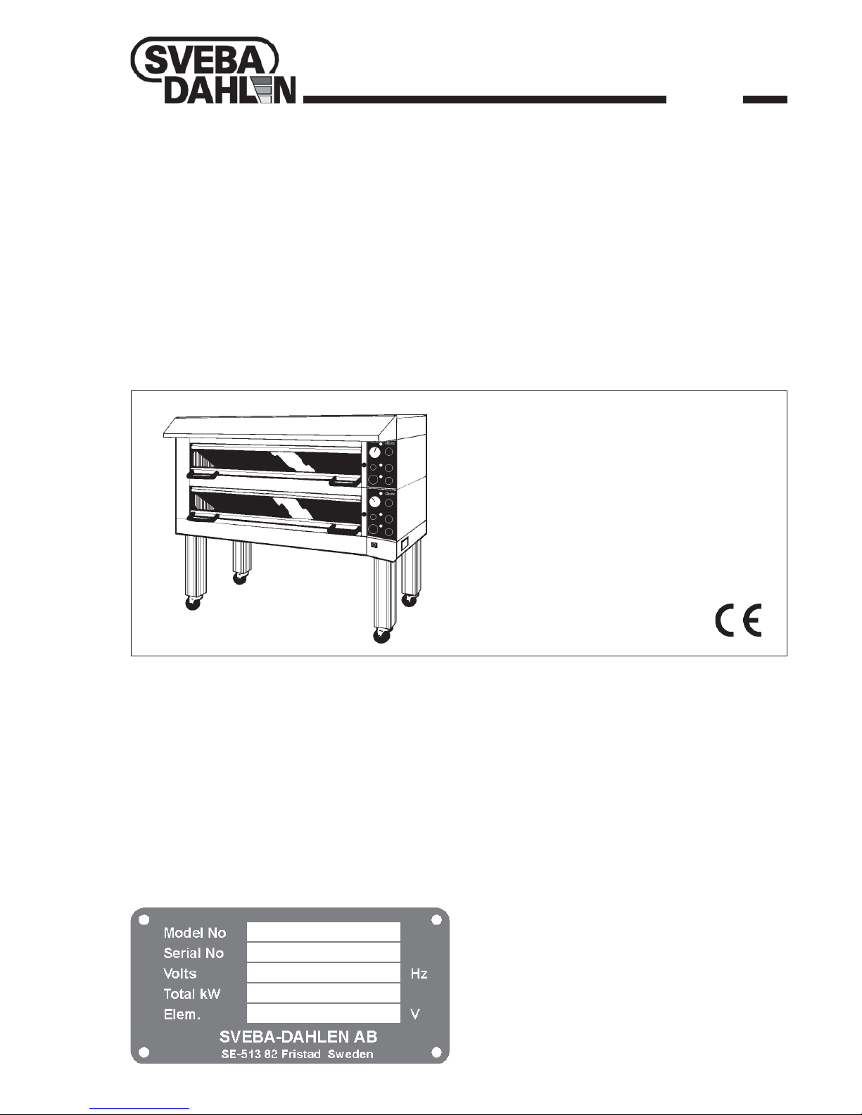
Sveba Dahlen AB Classic DC-1, Classic DC-2, Classic DC-2E, Classic DC-3, Classic DC-4 Operating & Installation Manual
Page 1
Classic
Deck oven
Type: DC-1 DC-2 DC-2E DC-3 DC-4
Operating
Maintenance
Installation
Rev.3
860004-02
Page 2
2
Operating Maintenance Installation CLASSIC 3:3500-2 --> 860004-02
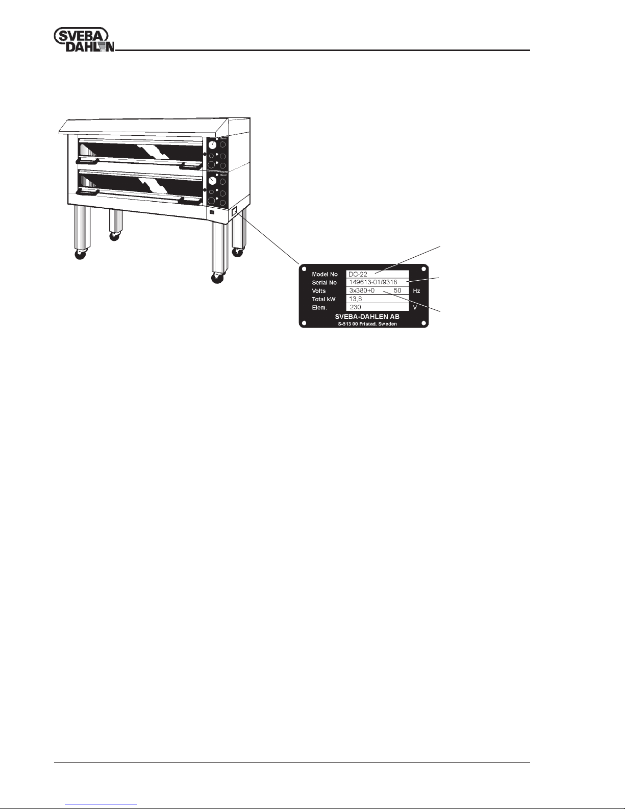
Data plate.
Positioning of data plate.
Data plate for Classic Deck Oven
Model designation
Serial number
Connected voltage
To obtain assistance with installation or service of the oven the oven serial number and
model desig-nation must be given.
Note the serial number, model designation and voltage so that they are readily available
when contacting us.
Please direct all your questions, comments or technical problems regarding this product
to the SVEBA-DAHLEN dealer or directly to
SVEBA-DAHLEN AB
SE-513 82 Fristad
Sweden
Tel. +46 33 151500
Fax +46 33 151599
Web: www.sveba-dahlen.se
Mail: [email protected]
Subject to changes without notice
Page 3
3
Operating Maintenance Installation CLASSIC 3:3500-2 --> 860004-02
TABLE OF CONTENTS
TABLE OF CONTENTS . . . . . . . . . . . . . . . . . . . . . . . . . . . . . . . . . . . . . . . 3
TECHNICAL DATA . . . . . . . . . . . . . . . . . . . . . . . . . . . . . . . . . . . . . . . . . . . 4
DESCRIPTION . . . . . . . . . . . . . . . . . . . . . . . . . . . . . . . . . . . . . . . . . . . . . . 5
INSTRUMENT PANEL . . . . . . . . . . . . . . . . . . . . . . . . . . . . . . . . . . . . . . . . 6
BAKING . . . . . . . . . . . . . . . . . . . . . . . . . . . . . . . . . . . . . . . . . . . . . . . . . . . 8
BAKING - PERSONAL SETTINGS . . . . . . . . . . . . . . . . . . . . . . . . . . . . . . . 9
CARE AND MAINTENANCE . . . . . . . . . . . . . . . . . . . . . . . . . . . . . . . . . . . 10
TROUBLE SHOOTING . . . . . . . . . . . . . . . . . . . . . . . . . . . . . . . . . . . . . . . 11
DISTRIBUTION BOX . . . . . . . . . . . . . . . . . . . . . . . . . . . . . . . . . . . . . . . . 12
UNPACKING . . . . . . . . . . . . . . . . . . . . . . . . . . . . . . . . . . . . . . . . . . . . . . . 13
ASSEMBLY . . . . . . . . . . . . . . . . . . . . . . . . . . . . . . . . . . . . . . . . . . . . . . . . 15
INSTALLATION . . . . . . . . . . . . . . . . . . . . . . . . . . . . . . . . . . . . . . . . . . . . . 17
Page 4
4
Operating Maintenance Installation CLASSIC 3:3500-2 --> 860004-02
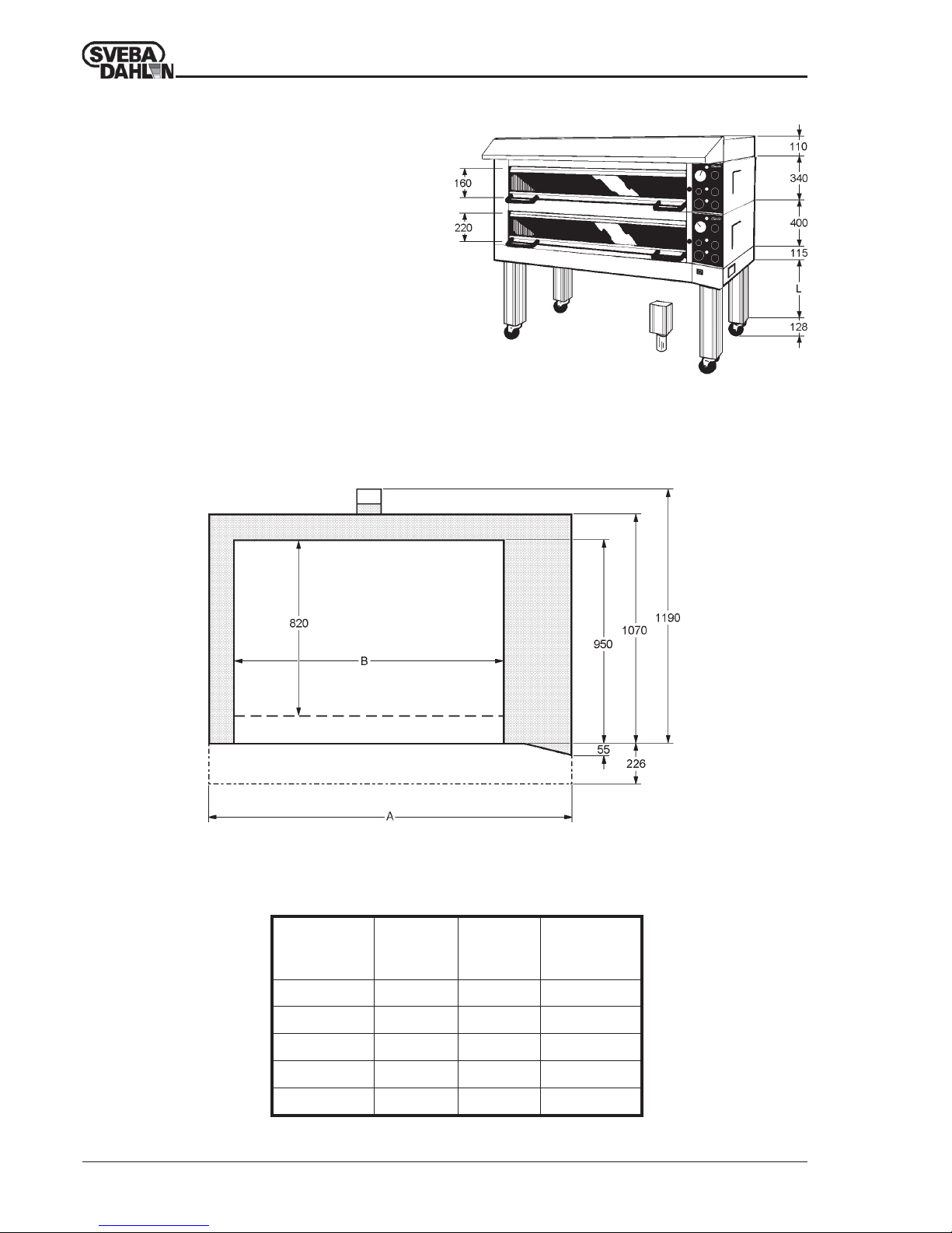
The oven chamber is available in five widths (Fig. 2) and
two heights, 160 and 220 mm.
Fig. 1 shows an oven where a low oven chamber is
mounted over a high one.
Low and high oven chambers can be combined to form
5 decks of oven chambers.
The leg length L can vary from 0 to 900 mm.
Standard leg length is 100, 200 and 300 mm,
etc. but other lengths are available on request.
Castors or feet can be fitted directly to the oven
bottom.
Technical data
Table 1 Dimensions and outputs for Classic
Fig. 1 Height of Classic in mm.
Fig. 2 Dimensional drawing for Classic
TECHNICAL DATA
DC-1 1075 635 5,0
DC-2 1390 950 6,9
DC-2E 1705 1265 8,8
DC-3 2020 1580 10,7
DC-4 2335 1895 12,6
Oven A B Connected
model mm mm power
kW
Page 5
5
Operating Maintenance Installation CLASSIC 3:3500-2 --> 860004-02
DESCRIPTION
Design principle
The deckoven is CE-approved according to EMC, LVD
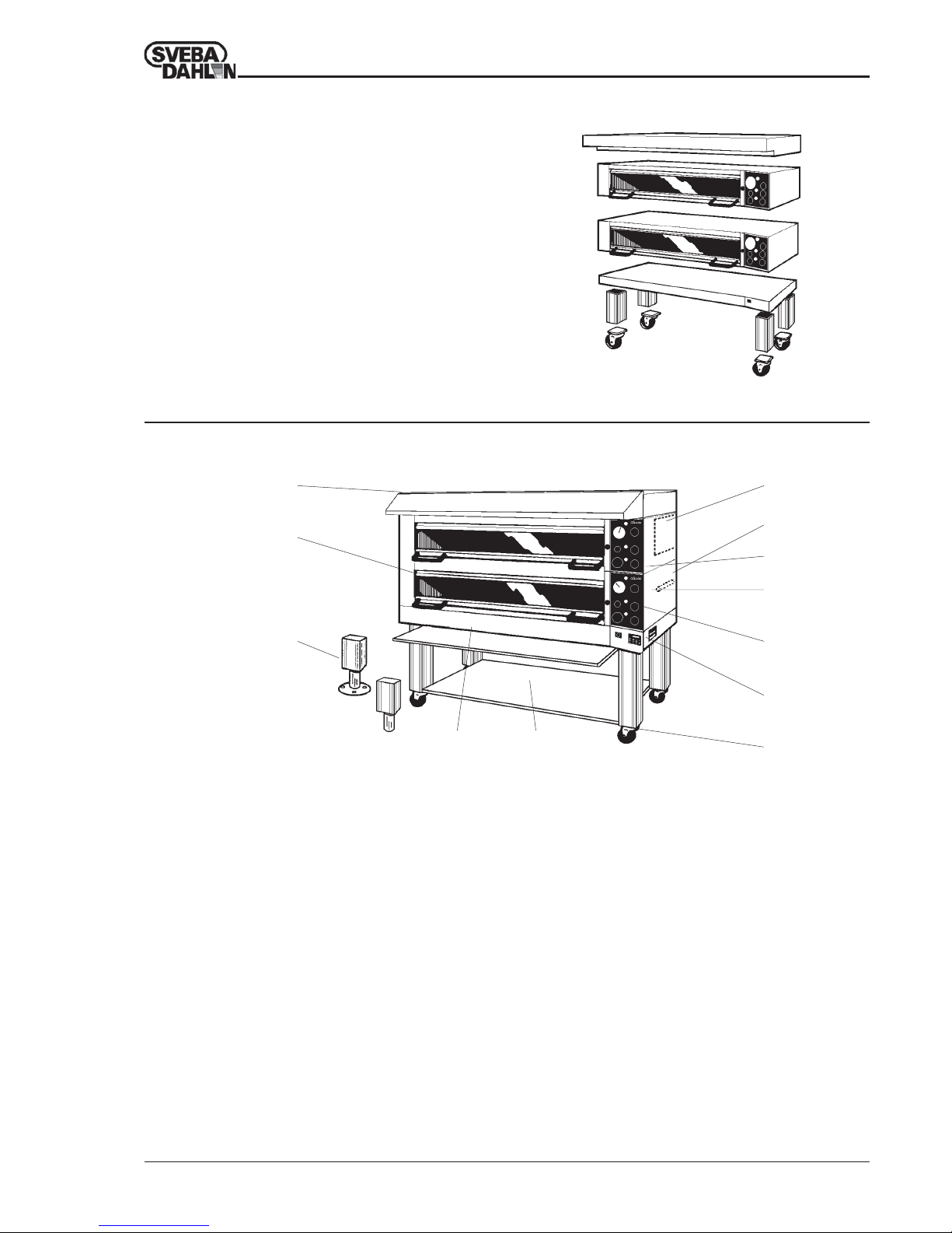
The deck oven is manufactured in detachable sections.
The advantage of this is that the sections can be combined
to suit special purposes or areas. This makes the oven
easy to install.
One, or up to five oven sections ca be placed between the
bottom and top, which can be low, high, or an optional
combination of both heights.
The legs are then fitted to the bottom, and can be supplied
with castors or adjustable feet.
Fig. 3 The Classic modules
12
11
10
9
61
3
2
45
Fig. 4 Accessories for Classic
7
8
1 Canopy
The canopy collects and removes steam and smoke
from the oven chamber.
2 Stone sole
For baking direct on the sole.
3 Marine version
Special version for baking and preparing food on
ships. The oven is electrically adjusted for marine
use. The bottom and back-panels are also made of
stainless steel.
4 Pull out shelf
Practical working shelf which can be pulled out
from the oven. Can not be used when the oven is
placed on an underbuilt prover.
5 Shelf stand
Practical shelf for storage of tins, kitchen utilities,
etc.
6 Built-in steam generator
Effective steam generator for baking with steam.
7 External steam connection
Used when there is a steam boiler in the bakery.
8 Turbo-start
Gives quicker heating at the simple press of a
button when starting the oven, and reduced reheating times when baking, irrespective of heat
control setting.
9 Electronic power control
Power control for baking with high standards.
Gives smooth heating. Turbo-start included.
10 Digital instrument panel
Digital instruments for temperature and baking
times. Electronic power control and Turbo-start
included.
11 Digital week timer
Timer which starts the oven and prover automatically every day.
12 Castor
The oven can be fitted with castors to facilitate
moving.
Accessories for Classic Deck Oven
Page 6
6
Operating Maintenance Installation CLASSIC 3:3500-2 --> 860004-02
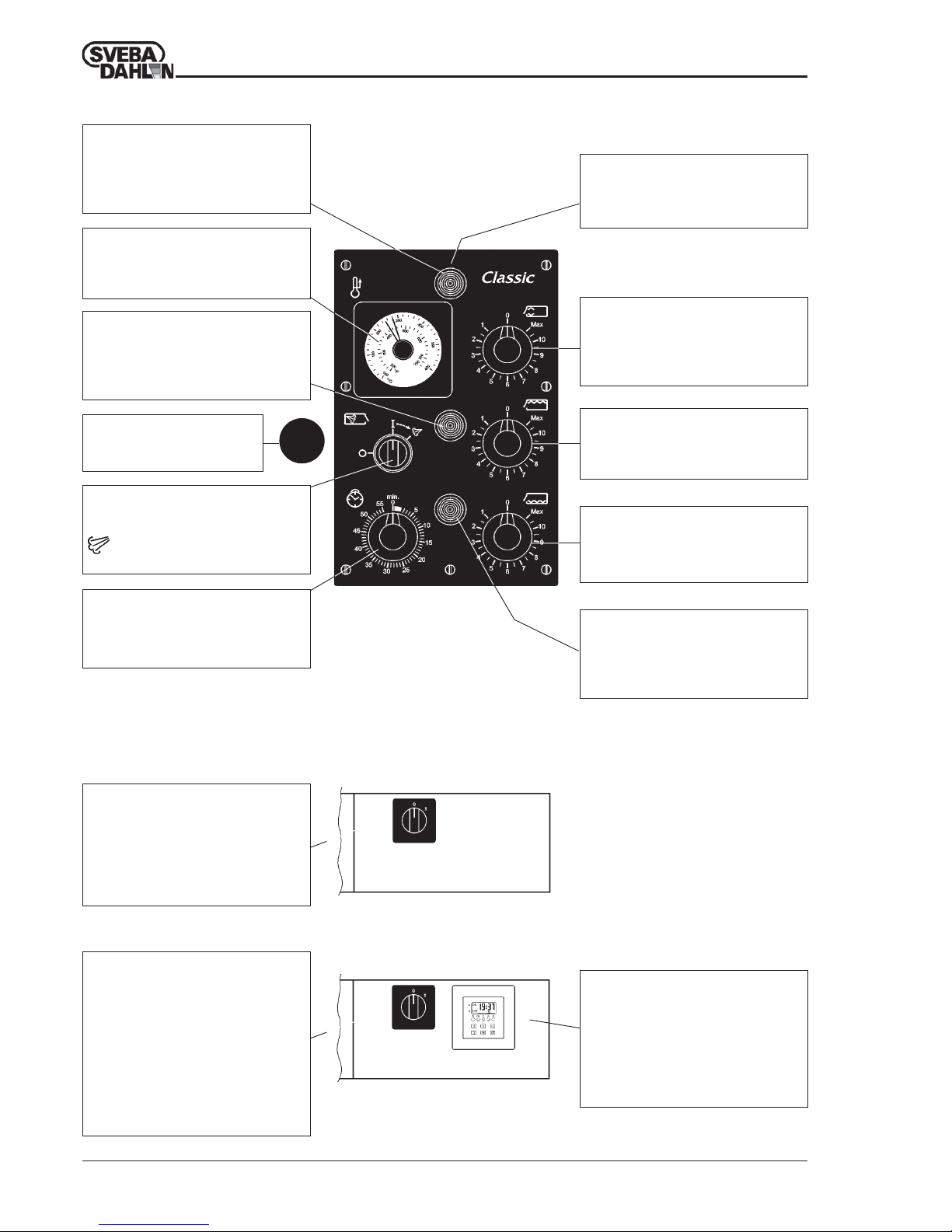
Thermostat
Regulates the temperature in the oven to
the temperature which is set on the
thermostat.
Steam indicator, red
When the lamp goes off the steam generator is ready for use. When the lamp
lights the steam generator is heating up
and cannot be used.
Control switch for steam generator
O - Steam generator switched off
I - Steam generator switched on
- Steam sprayed in for time fixed
by relay in distribution box.
Control for top heat
Regulates the heat from the top elements.
Turn the control to the O position when
this section is not used.
Control for bottom heat
Regulates the heat from the bottom
elements. Turn the control to the O position when this section is not used.
Control switch
O - Off
I - On
Breaks the control current to all oven
sections.The current must be broken with
the main oven switch before carrying out
service work.
Control switch
O - Off
HAND - On
AUTOM - Automatic
Breaks the control current to all oven
sections. In pos. AUTO the oven is stopped
and started at the times prog-rammed in
the week timer.
The current must be broken with the main
oven switch before carrying out service
work.
Fig. 5 Standard panel with
steam control.
Fig. 7 Control panel with week timer
Fig. 6 Standard control panel
INSTRUMENT PANEL
Heat indicator, yellow
The lamp lights when the temperature
falls below set temperature. The lamp
goes off when the set temperature is
reached.
Control for front heat
Regulates the heat at the front of the oven.
(Over and under the door). Turn the control
to the O position when this section is not
used.
Turbo knob
Max. load on top- and bottom
elements until the thermostat breaks the
first time.
Baking timer, 2-55 min.
Emits audio and lamp signal when the set
baking time has expired. Audio and lamp
signal set to zero by turning dial.
Damper Control
Pushed-in - Closed
Pulled-out - Open
Baking time indicator, green
The lamp lights when the baking time has
expired and indicates which section of
the oven is ready. An audio signal is given
while the lamp is on.
Week timer (option)
Two-channel timer for automatic start
and stop of oven. As an option also for
underbuilt prover. The oven and prover
can be programmed for different start and
stop times. The start and stop times can
also be varied for all days in the week.
Page 7
7
Operating Maintenance Installation CLASSIC 3:3500-2 --> 860004-02
INSTRUMENT PANEL
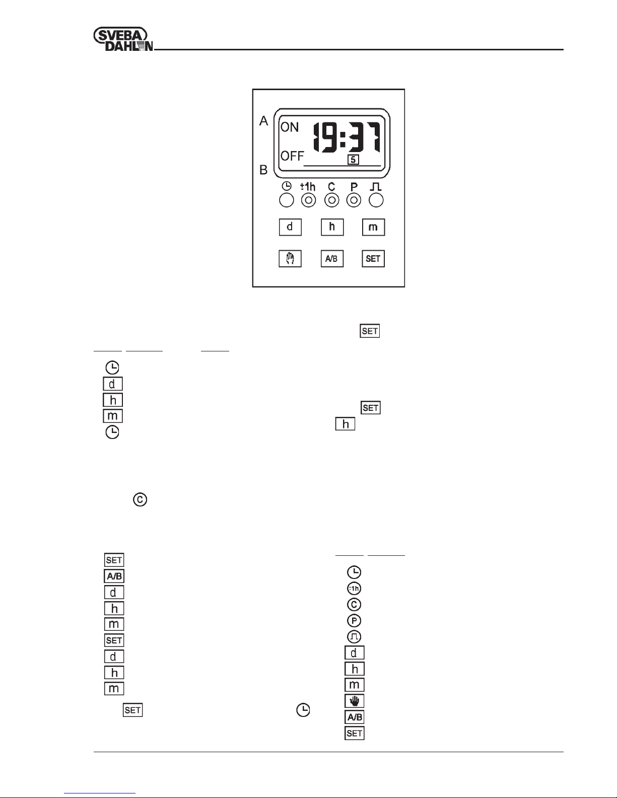
Functions of the buttons
Button Function
Setting the time, reset to running time.
Switching of daylight-saving time
Reset button
Programming button
Return to timer function / Pulse programming
Setting the day
Setting the hour
Setting the minute
Manual on/off switch for the function
Selection of channel
Setting or changing the switching function
Weekly timer
Setting the time and the day of the week
Example: setting the timer for Wednesday, 3:22 p.m.
Button Function Action
Setting of timer Press once
Day of the week Tryck till 3.
Hour Press to 15.
Minute Press to 22.
Save Press once.
Setting a switching function
1.
On is shown in the display
2.
choose channel a or b
3.
select starting day or block of days
4.
select starting hour
5.
select starting minute
6.
Off is shown in the display
7.
select ending day or block of days
8.
select ending hour
9.
select ending minute
Select
for the next switching function or to
return to real-time display.
When first using the equipment, or when the equipment
has been out of use for a longer time, let the timer be
connected to the mains during approx. one minute. Then
press the
button, and the display will light up after
about 75 seconds.
Changing the switching function
Press
until the correct time is shown, then change
according to the above procedure.
Erasing the switching function
Press
until the correct time is shown, then press
until ”—:—” is shown in the display.
Page 8
8
Operating Maintenance Installation CLASSIC 3:3500-2 --> 860004-02
BAKING
Table 2 Setting for common products.
Where double temperatures are given (Temp. 1/Temp. 2) this refers to initial temperature and final baking temperature.
Heat controls
The Classic Deck Oven is fitted with three groups of
elements which can be regulated separately. These groups
are called TOP HEATING, BOTTOMHEATING, and
FRONT HEATING.
Top and bottom heating are used to influence the
properties of the baked product. The main purpose of the
front heating is to compensate for the heat losses at the
oven door.
Certain commissioning time can be expected before you
find your own settings for Your products.
To start with you can use the values in the table below,
and then adjust to your own settings.
Heating up of the oven.
The time it takes to heat up the oven depends on the
setting of the heat controls. The quickest way of heating
up the oven is to turn the three heat controls to MAX.
200°C is reached after about 27 minutes, and 250°C after
about 35 minutes. Please wait for a further 15-20 minutes
before the first bake to give the temperature in the oven
time to equalize.
Cooling of the oven
To cool the oven quickly turn down the thermostat and
open dampers and doors fully or partially. The heat
controls should also be set to zero or else the thermostat
can switch on the heat again if the temperature falls
below the set value.
Bread loaf 8 8 6 250/220 20 Yes
Tin bread 3 3 7 240 30 Yes
Round flat bread 8,5 7,5 7 240 12
French loaf 8 8 6 270/235 20 Yes
Baguettes 8 8 6 270/250 20 Yes
Rolls 8,5 8,5 7 250/240 8 Yes
Wheat bread 6 6 2 200 20
Plain buns 9 9 2 240 8
Danish pastries 9 9 2 240 8
Macaroon 6 6 3 180 18
Sponge cake 3 3 7 180 50
Cake 6 6 6 200 25
Product
Front
heat
To p
heat
Bottom
heat
TempºCBake time
min.
Steam
Page 9
9
Operating Maintenance Installation CLASSIC 3:3500-2 --> 860004-02
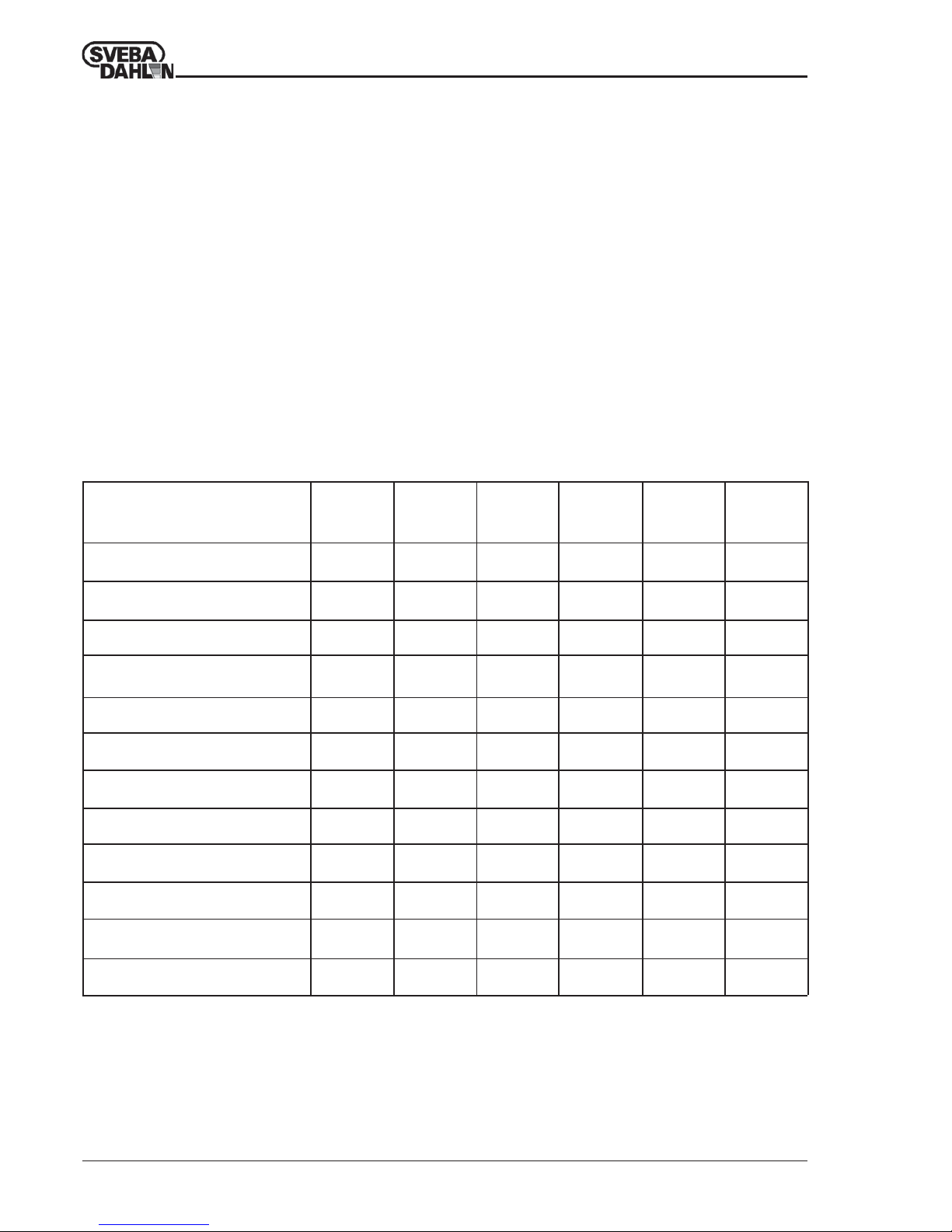
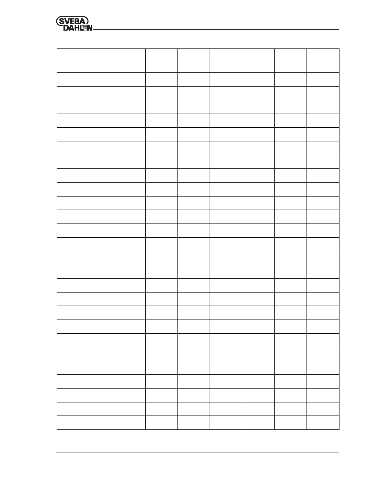
BAKING - PERSONAL SETTINGS
Table 3 Personal settings
Product
Front
heat
Top
heat
Bottom
heat
Temp.ºCBake time
min.
Steam
Page 10
10
Operating Maintenance Installation CLASSIC 3:3500-2 --> 860004-02
CARE AND MAINTENANCE
Brush out the oven chamber regularly from bread crumbs
and soot.
Wipe off the door glass inside and out with a moist cloth
with a little detergent.
You can do this when the door is warm, but not over
60°C. If the door is too hot the temperature difference
between the cloth and glass may crack the glass.
Keep your glass clean or else it will be difficult to
remove grease which has burned on.
OVEN CLEANER is an appropriate detergent for glass
and inside of the oven.
It can be purchased directly from Sveba-Dahlen, Art. no.
80073-02.
Do not use alkaline or abrasive detergents!
When cleaning oven chamber, make sure that no rests of
detergent are left after cleaning.
Sveba-Dahlen has an excellent detergent for the exterior
of the oven: LAHEGA, Art no. 91430-009.
For final cleaning of the glass we recommend BRITE
GLAZE, Art. no. 91430-005.
Call us on phone number +46 33 151500 or fax us on fax
number +46 33 151599.
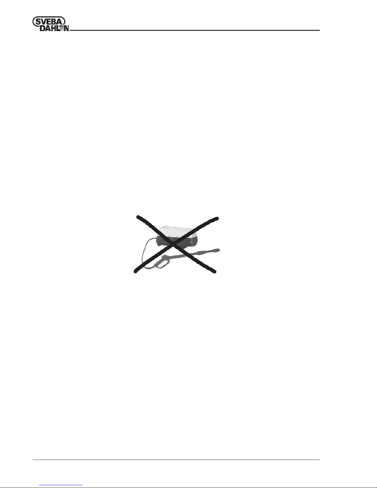
The oven must not be sprayed with water since this
can result in short circuiting and corrosion damage
on concealed areas of the oven.
If the oven insulation becomes wet the temperature of
the exterior plates will increase considerably.
Page 11
11
Operating Maintenance Installation CLASSIC 3:3500-2 --> 860004-02
TROUBLE SHOOTING
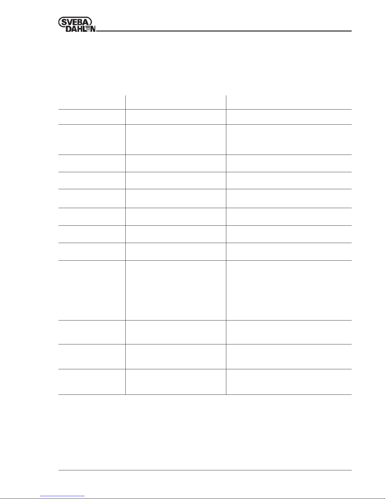
Table 4 Trouble shooting.
Trouble shooting
In the event of a problem you should first look through the trouble shooting list below to see if you can
correct the fault yourself. If this does not help contact Sveba-Dahlen’s service department.
NOTE! Work on electrical components must be carried out by an authorized electrician.
The oven does not start.
• Oven fuse blown.
• Main fuse blown.
• Reset fuse in the oven distribution box.
• Replace fuse in the main distribution box.
Fault Reason Procedure
The oven drops in
temperature or has long
recovery time.
• Damper open.
• A fuse/overheating protection has blown.
• Defective element.
• Close damper fully or partially.
• Reset fuse/overheating protection in the oven
distribution box.
• Replace defective element.
The top of the product is
too dark.
• Too much top heat
• Reduce top heat.
The bottom of the product
is too dark.
• Too much bottom heat. • Reduce bottom heat.
Both the top and bottom of
the product are too dark.
• Too high baking temperature.
• Too long baking time.
• Reduce baking temperature slightly.
• Reduce baking time slightly.
The product is lighter at the
front of the oven.
• Too little front heat.
• Too much top heat.
• Increase front heat 1 step.
• Reduce top heat 1 step.
The product is darker at the
front of the oven.
• Too much front heat.
• Too little top heat.
• Reduce front heat 1 step.
• Increase front heat 1 step.
The oven bakes unevenly
on certain surfaces.
• Defective contactor.
• Replace defective contactor.
Note: only by authorized electrician.
No steam in the oven
chamber.
• Steam generator is switched off.
• Water in steam generator is turned off.
• Dirt in steam generator nozzle.
• Steam generator fuse blown.
• Steam generator element defective.
• Steam generator pilot lamp on.
• Steam generator time relay incorrectly set.
• Steam generator time relay defective.
• Start steam generator with steam control.
• Open water tap.
• Remove and clean nozzle.
• Reset steam generator fuse.
• Replace defective element.
• Wait until lamp goes off.
• Adjust steam time on relay (approx. 20 sc.).
• Replace defective time relay.
Too little steam in the oven.
• Steam time too short.
• Dirt in steam generator nozzle.
• Oven damper open.
• Reduce time on steam generator time relay.
• Remove and clean nozzle.
• Close damper fully or partially.
Too much steam in the
oven.
• Steam time too long.
• Water pressure too high.
• Reduce time on steam generator time relay.
• Reduce time on steam generator time relay or
replace with small nozzle.
The bread lacks lustre
despite adequate steam.
• Oven damper is open.
• Steam applied too late.
• Close damper fully or partially.
• Put products more quickly into oven and start steam
immediately.
Page 12
12
Operating Maintenance Installation CLASSIC 3:3500-2 --> 860004-02
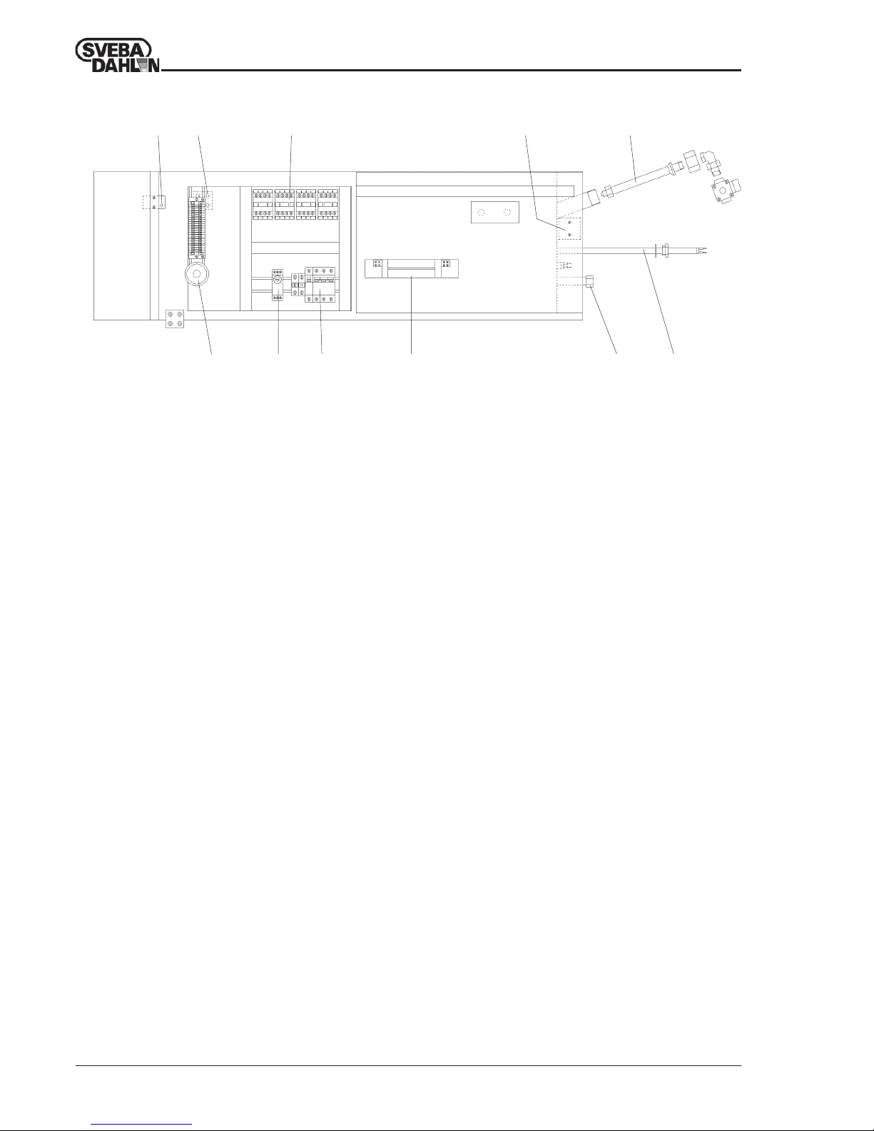
12 3 7 8
245 6 910
1 Overheating protection
To get a complete disconnection, the fuse F1 of the
elements will also trip (see point 5 too).
If the overheating protection has triggered this can be
reset by pressing the reset button with a pen. The
button is reached through the small round hole in the
oven right-hand side panel.
Never use electrically conductive object when
resetting! Call technician if the protection triggers
repeatedly.
2 Buzzer
This is connected to the baking timer and gives a
signal when the baking time has expired. At the same
time as the buzzer is activated the green pilot lamp on
the instrument panel lights.
3 Contactor
One contactor for each group of elements, top, bot
tom and front heat. If the oven is fitted with a builtin steam generator, there is a fourth contactor for this.
4 Time relay 0-100 seconds.
This relay only exists if the oven is fitted with steam
generator. The relay decides how long steam will be
sprayed into the over chamber when the steam control
on the front panel has been turned to the steam
position. The relay is set to 20 seconds on delivery but
can be adjusted where necessary.
Never use longer steam times than necessary since
this will reduce the capacity of the steam generator.
Fig. 12 Distribution box
DISTRIBUTION BOX
5 Automatic fuse
The 3-pole fuse protects the oven elements. On the
lower section there is also a 1-pole fuse. This is the
oven control fuse and is common to all sections in
the oven.
During service work in the oven the power supply to
the oven must be switched off. It is not sufficient to
switch off the oven built-in automatic fuses.
6 Light transformer
Transformer for the halogen light. Two lamps are
connected to each transformer.
7 Thermostat 300-350°C
Thermostat for regulating the steam generator. The
temperature is locked and cannot be changed.
8 Nozzle pipe
There is a nozzle on the pipe which disperses the
water into the steam generator. In the event of inferior
steam function the pipe can be removed and cleaned.
The nozzle at the end of the pipe is dismantled after
which the strainer and nozzle can easily be cleaned.
9 Drain pipe
This pipe is plugged on delivery. We recommend that
this pipe be connected to a drain by means of a steam
trap. This considerably lengthens the service-life of
the steam generator and its elements.
10 Element
The steam generator has four 500 W elements.
Page 13
13
Operating Maintenance Installation CLASSIC 3:3500-2 --> 860004-02
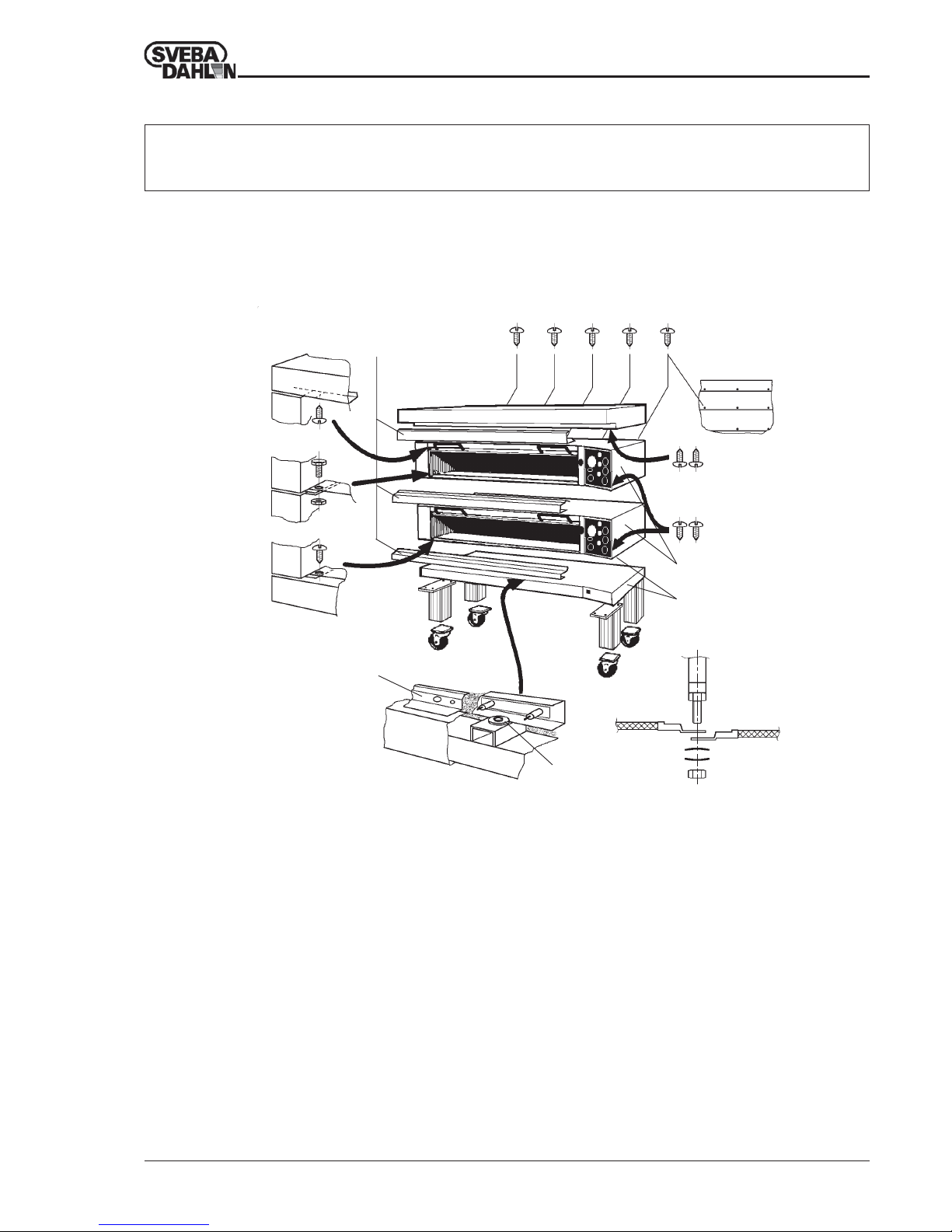
Open the packing materials carefully so that the oven is not damaged. Inside the oven chamber there are
several parts which must be used during assembly. Take these out and check with the enclosed packing list.
They should include the oven legs, feet or castors, heat distribution plate, hearth grid, distance bumper,
washers for cable inlets, screws and nuts.
1 Unscrew the cover plates at the front of the oven. On
ovens with one oven section there are two cover plates,
and on other ovens three or more.
2 Loosen the screws which connect the top section with the
top (2a) and the screws between the sections (2b). If
necessary the screws which connect the bottom section
with the bottom (2c) can also be loosened. Read more
about this in item 6.
3 Loosen the screws which connect the right-hand front
panel with the top, and the screws between the front
panels, and if necessary also the screws between the
front panel and the bottom.
4 Loosen the screws at the back of the oven along the joint
between the section and the top, between the sections,
and if necessary between the bottom section and the
bottom.
5 Mark up and loosen the cables in the distribution box
which are drawn between the sections and shall be
separated. The thick power cables (4-5 pcs) are
appropriately loosened at the automatic fuses, the thinner
cables (2 pcs) are loosened at the terminal blocks, and the
light cables (2 pcs) are loosened at the light transformer.
6 The bottom section and the oven bottom should not be
separated. If it is necessary to separate the oven also here,
do as follows:
Begin by marking up where and how all the element
cables are positioned, and then loosen these.
7 Loosen the cover plate behind the cables and lift this off
the insulation material behind.
8 Loosen the three screws with their clamp washers so that
the underlying plate strip releases. The oven section can
now be lifted off.
When the oven is to be assembled again it is important
that the plate strip is clamped again under the washers.
Now replace the insulation material, fit the cover plate
(7) and connect up the element cables again.
9 It is very important that the cables are correctly located,
and that both cup washers are turned towards each other
before they are screwed together.
2c
2b
2a
Assembly of oven parts.
1
7
8
3
6
5
4
9
Fig. 13 Dismantling of Classic.
UNPACKING
Read carefully through this manual before unpacking the oven.
Incorrect handling can damage the oven during transport and installation.
Page 14
14
Operating Maintenance Installation CLASSIC 3:3500-2 --> 860004-02
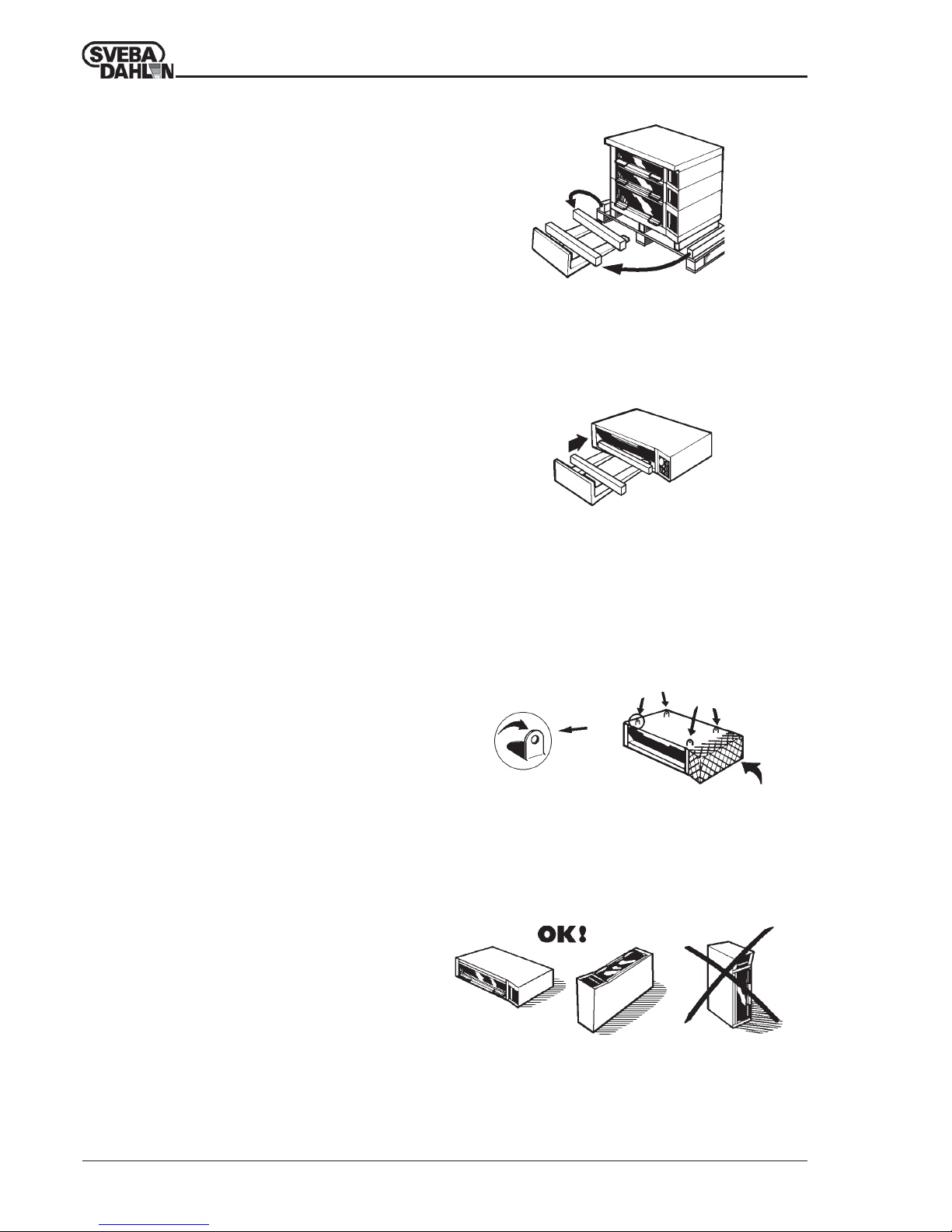
Fig. 14 Lifting of the parts of the oven.
Use the planks from the loading pallet when lifting off the oven
section.
Fig. 16 Lifting of section in lifting hooks.
Never lift or pull on the area of the oven which is marked!
Fig. 15 Lifting of section with fork-lift truck.
Watch out for the door and the window! The planks should be
at least 75 mm high. Never lift more than one oven chamber
at once in this way!
• When the oven sections are separated from each
other they can be carefully lifted down and moved to
the place of assembly.
• Use the planks from the loading pallet and place
these on the forks of the truck as spacers to
protect the oven door (Fig. 14).
• Now lift off one section at once (Fig. 15).
• The sections can also be lifted in their lifting
hooks, which are partially concealed under the
insulation. The hooks at the front of the oven roof
are to be turned up 90° before use (fig. 16).
• Do not put down or carry an oven section with the
short side down (Fig. 17). The oven has no
reinforcements for this type of strain, and there is a
risk for deformation.
If the section is put down on the back-piece, make
sure that the underlayer is flat. A spot load such as a
door threshold can easily crack the back-piece.
Observe care with protruding parts such as the solenoid
valve or the connection head of the element in the
distribution box.
• When all parts are lifted into position the assembly
of the oven can begin.
Fig. 17 Never put an oven section down on its side!
Watch out for extruding parts such as the damper or solenoid
valve.
UNPACKING
Page 15
15
Operating Maintenance Installation CLASSIC 3:3500-2 --> 860004-02
3
BSS B10x32
BSS B10x13
M6S 6x16
+ M6M 6
3
BSS
B10x13
4
5
BSS B10x13
2a
1a
M6S 8x20
+ M6M 8
7
6
6
BSS B10x13
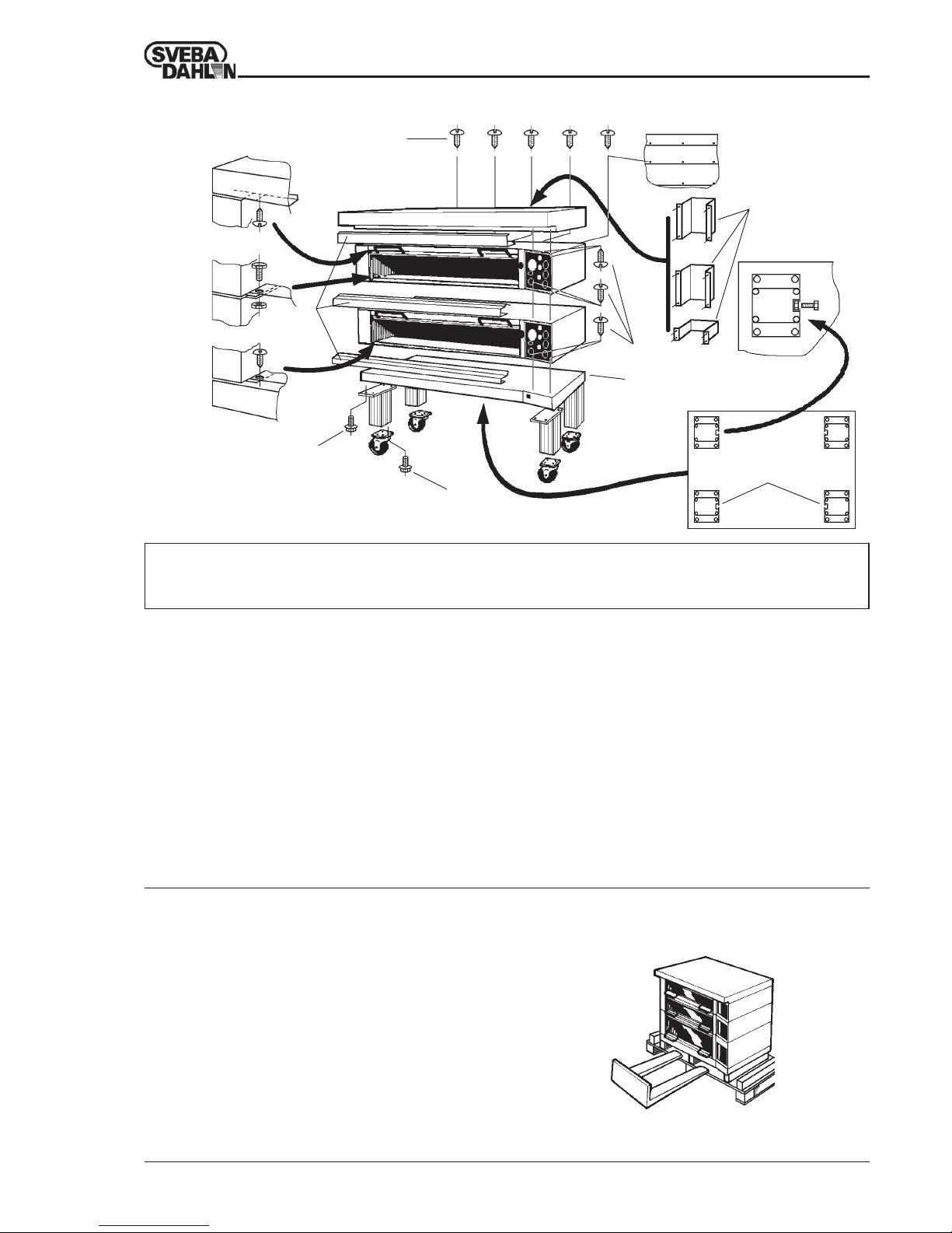
Electrical work, the connection of water and ventilation, must be
executed by an authorized technician.
1 Begin by screwing on the adjustable feet or castors
on the the oven legs. If the oven is to be fitted with a
removable shelf, or a fixed shelf, M8x16 screws must
be pushed into the external groove on each leg before
the feet or wheels are fitted (1a).
2 Screw on the legs in the bottom section. The helicoidal
grooves in the legs must be turned towards each other
(2a).
3 Lift up all the oven sections incl. the top on the
bottom section, and screw together.
4 Fit the cover plates which protect the element cables
in the front of the oven. Check that all the closed oven
doors fit tightly to the cover plates.
5 Screw on the exhaust ducts at the back of the oven.
The thin end must face downwards. Now screw on
the distance bumper down on the bottom section. The
distance bumper protects the wall behind from the
hot exhaust duct.
6 Connect up all loose cables and make extra sure that
they are connected correctly again.
7 Connect the incoming electric cable to the terminal in
the bottom section. A number of flat washers to fit the
cable screw unions are enclosed on delivery. Finally,
check that no screws or cables are loose.
Fig. 18 Assembly of dismantled oven.
1
M6S 8x20
+ BRB 8.4x17
2
M6S 8x20
+ BRB 8.4x17
ASSEMBLY
The figures in the text refer to the text above, ”Assembly
of a dismantled oven”.
• Open the packing materials carefully so as not to
damage the oven.
• Fit the oven legs as per items 1 and 2.
• Carefully lift up the oven from the transport pallet and
pull this out of the way. Screw on the oven legs in the
oven bottom, see item 2. Put the oven down again.
• Fit the exhaust ducts and distance bumper, see item 5.
• Connect the incoming electric cable, see item 7.
Assembly of a complete oven
Fig. 19 Lifting of a complete oven.
Page 16
16
Operating Maintenance Installation CLASSIC 3:3500-2 --> 860004-02
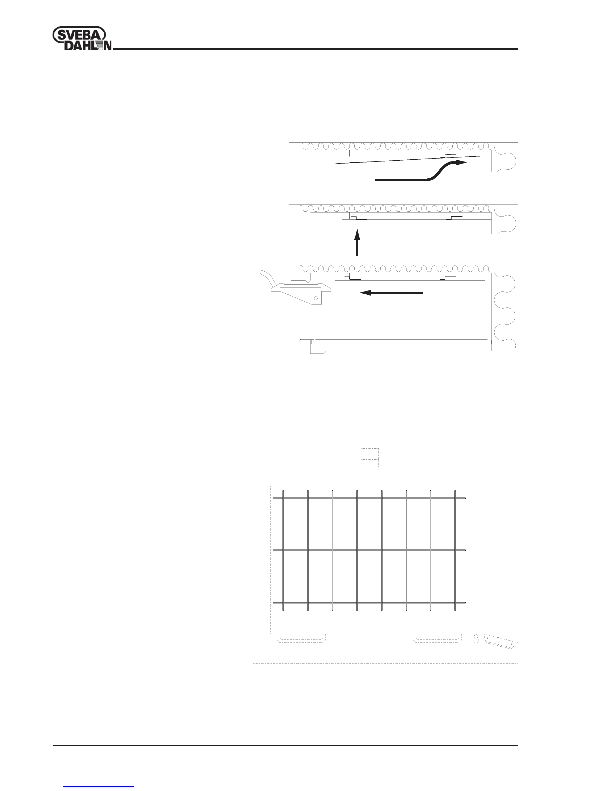
Fig. 21 Hearth grid for more even bottom heat.
Fig. 20 Assembly of heat distribution plate.
ASSEMBLY
Hearth grid.
The hearth grid is another quality improving
part which is enclosed with the oven.
The grid equalizes the bottom heat and prevents
uneven colouring on the bottom of the products.
This phenomena can occur when baking with
uneven baking trays.
The hearth grid is put onto the oven hearth and
only needs to be lifted out for cleaning.
Heat Distrubution Plate
The heat distrubution plate distributes the heat
from the upper element so that even sensitive
products are perfectly baked.
1 Push in the plate into the oven chamber
with the long hooks first, and hang up these
in the rear element support.
2 Lift up the front part to the front element
support.
3 Pull back the plate so that the front hooks
are pushed fully into the front element
support.
1
2
3
Page 17
17
Operating Maintenance Installation CLASSIC 3:3500-2 --> 860004-02
INSTALLATION
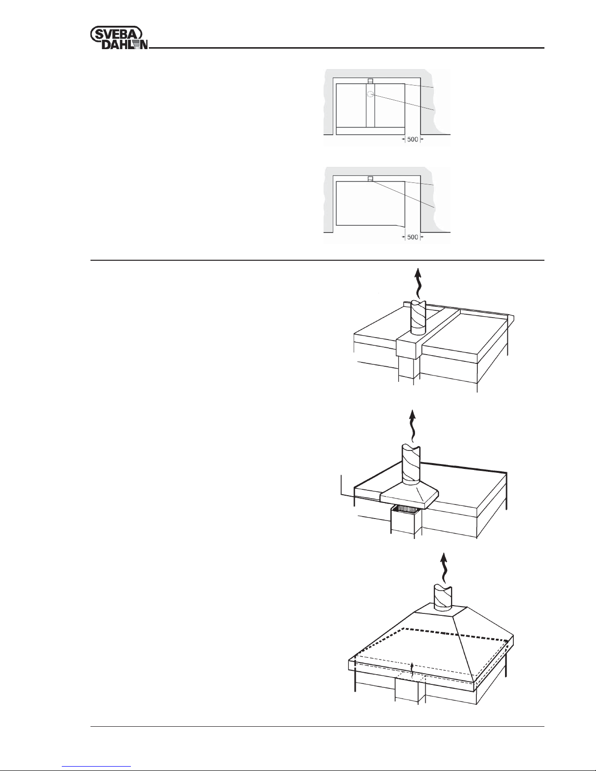
Ventilation and suction ducts are fire classed, and
must therefore be insulated and fire classed as per
current regulations.
The air which is led off via the ducts has a temperature
of approx. 50-80°C if the installation is executed as per
Fig. 23 or 24. The air volume which is led off it approx.
150-200 m³/h.
Exhaust ducts Fig.23
To ensure that smoke and hot air from the oven do not
come into the room a ventilation duct must be fitted over
the oven exhaust duct.
The ventilation duct must under no circumstances be
connected directly to the oven exhaust ducts, if there
is no canopy installed in the oven.
There must always be some form of draught
interruption as shown in Fig.23b.
Exhaust hood Fig.24
If a hood is fitted over the entire oven it is not necessary
to fit separate exhaust ducts on the oven.
The hood should be approx. 0.5 metres larger than the
external contours of the oven to be able to trap smoke and
hot air.
Connection to ventilation duct.
Positioning
Fig. 22a Positioning of oven with canopy
Connection to canopy
Ø125mm
Water or steam connection
Electrical connection
Leave a 500 mm free space on the right-hand side of the
oven. This space is needed for access to the oven
distribution box during installation and service.
If the oven is fitted with built-in steam generator an
additional 200 mm wide space is needed between the
wall and the back of the oven.
This space is needed for taking out the steam generator
water nozzle for cleaning.
Fig. 22b Positioning of oven without canopy
Connection to oven exhaust
duct
Water or steam connection
Electrical connection
Fig. 23a Connection to exhaust duct / canopy.
150-200 m³/h
60-80ºC
Fig. 23b Connection to exhaust duct.
Exhaust duct
approx. 100 mm.
150-200 m³/h
60-80ºC
Fig. 24 Exhaust hood over the oven.
150-200 m³/h
60-80ºC
Page 18
18
Operating Maintenance Installation CLASSIC 3:3500-2 --> 860004-02
INSTALLATION
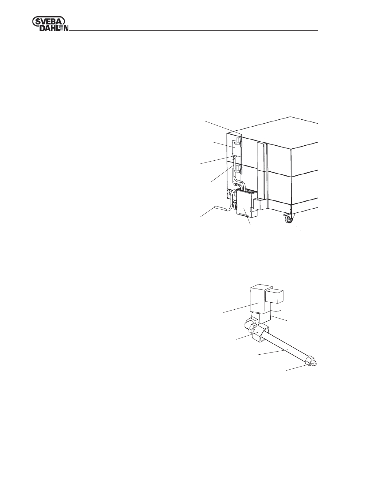
Connection of water.
If the oven is fitted with a built-in steam generator this
must be connected to cold water.
Connection is made to the solenoid valves (figs. 25,
26) on the rear of the oven.
Water pressure should be 4-6 bar (60-85 psi). Lower
water pressure gives lower steam capacity.
To avoid malfunction, it is important that the pipe is
flushed carefully, so that any rubbish left inside does
not block valves and nozzles.
If the water contains dirt particles, e.g. rust, a filter
should be installed upstream of the valves. This
reduces the risk of malfunctions.
If the water is very hard, a water softener should be
installed upstream of the valves to prevent lime
deposits from forming in the valves and nozzles. A
suitable water softener can be obtained from Sveba
Dahlen or one of our retailers.
The nozzle pipe seals to the steam generator with a
conical seal, and therefore no thread tape is needed
between the inlet pipe and the hexagonal cap.
Connection of drain.
Under the pipe there is a pipe which on delivery is fitted
with a 3/8" hexagonal cap. This pipe is a drain pipe from
the steam generator, and is used to empty the steam
generator of surplus water.
We recommend that the drain pipe should be connected
to a steam trap, so that the steam generator is
automatically drained after every steam cycle (Fig. 25).
The valves can also be drained manually.
A ball valve with drain pipe is fitted to each steam
generator. At least once a week the impurities in the
steam generator should be flushed out.
To do this open the ball valve and press the steam control
on the instrument panel. The impurities will then be flushed
out, which increases the service-life of the steam generator
and its elements. After this close the ball valve again.
The steam generator must be heated before it can be
flushed.
WARNING! Steam and hot water sprays out from
the drain pipe when flushing. This can cause
severe burns if you are careless.
Data: steam generator. (1 pcs. per oven section)
Output: 2000 W.
Water consumption: approx. 0.9 ltr/ steam cycle.
(Max. flow at 5 bar = 2.8 ltr/min.)
Water in
Pipe
Nozzle
Hexagonal cap
Solenoid valve
Fig. 26 Nozzle pipe
Union
G 3/8
Steam
generator
Union
G 3/8
Drain pipe
Drain
steam trap
Fig. 25 Connection of water and drainage
Steam trap (Accessories)
Page 19
19
Operating Maintenance Installation CLASSIC 3:3500-2 --> 860004-02
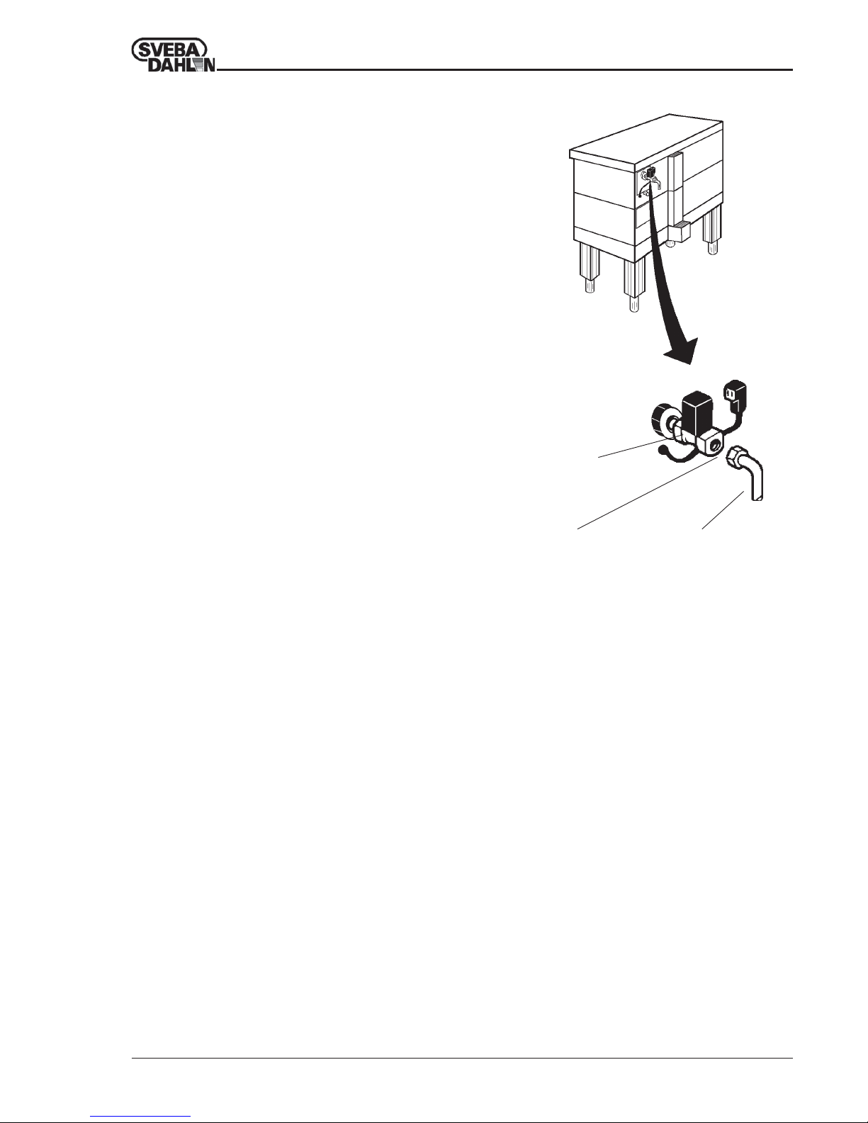
Connection of external steam.
Steam pipeUnion G 3/8
Fig. 27 Connection of external steam.
Steam valve
If there is a steam boiler in the bakery the oven can be
connected to it. This connection is made to the steam
valve on the back of the oven (Fig. 27).
The oven must be of the low-pressure steam type, and
have a connection pressure of approx. 0.5-0.9 bar (7-13
psi), and be free from water particles.
To ensure first-rate results and high reliability a
condensation separator and a ball valve should be fitted
before the oven steam valve.
When external steam is connected it is possible, where
so required, to extend the steaming time by increasing
the time of the time relay in the oven distribution box.
INSTALLATION
Page 20
20
Operating Maintenance Installation CLASSIC 3:3500-2 --> 860004-02
INSTALLATION
First start of the oven.
Before the oven is first used it must be burned out so that
residual protective oil in the oven chamber disappears.
During this procedure there will be a certain amount of
smoke from the oven, but this is quite normal. Make sure
that the ventilation system in the premise is in operation,
and can get rid of the smoke.
All oven sections can be burned out at the same time.
• Close all the oven doors, open all the dampers, and set
the thermostats to approx. 120°C.
• Turn all the heat controls to Max. position and start
the oven with the main switch.
• When the oven has reached 120°C allow to stand
for about 30 minutes. Afterwards wipe off the inside
of the door glass with a dry cloth or paper.
Make sure you don’t burn yourself.
In small premises with poor ventilation it is possible that smoke
detectors are activated during the burn-out.
Use maximum ventilation by opening doors and windows.
• Turn the thermostat to approx. 200°C. Let the oven
stand for about 15 minutes when this temperature has
been reached.
• Finally, set the thermostat to 240-250°C and leave the
oven to stand for about 2 hours. The oven will now be
ready to use.
• When the oven has been switched off and has
cooled, wipe the inside of the door glass with a
moist cloth. The coating on the glass which
developed during the burn-out will otherwise stick
tight and will be very difficult to remove.
Check that the overheating protection has not triggered. If necessary,
reset according to section "Distribution box" point 1.
Page 21
EU-Declaration of conformity
DOCUMENT
Sveba-Dahlen AB
Company
Manufacturer
Address Phone no.
+ 46 33-15 15 00SE-513 82 FRISTAD
Place Date
Fristad
Signature
Name Title
Managing DirectorBengt Gabrielsson
Company
Sveba-Dahlen AB
+46 33-15 15 00SE-513 82 FRISTAD
(Directive 98/37/EC, Annex II, A)
Address Phone no.
Declare under sole responsibility that the Deckoven
Classic model DC-1, DC-2, DC-2E, DC-3, DC-4:
, are in conformity with following standards or other normative
documents following the provisions in the COUNCIL’S
DIRECTIVES:
-of May 3 1989 ”relating to electromagnetic compatibility” 89/336/
EEC, and applicable supplements.
-of February 19 1973 ”low voltage directive” 72/23/EEC, and
applicable supplements.
The following standard(s) have been applied: EN50081-1.
 Loading...