

SVAT UC1700, SE UC1700 User Manual

SE UC1700
Hidden Colour Digital Video Capture Camera
Caméra Caché Visuel De Capture De Digital De Couleur
User's Manual
Manuel de l'utilisateur
www.svat.com

www.svat.com
IMPORTANT SAFETY PRECAUTIONS
PLEASE READ BEFORE INSTALLING
Congratulations on your purchase of the Hidden Colour Digital Video Capture Camera. Please
read these safety and operating instructions carefully before installing and using this system.
• Keep the camera, monitor and AC/DC adapter cords out of reach of children.
• Do not place the camera, monitor and AC/DC adapter cords in a crib or playpen.
• Do not use the camera near water or in damp and wet environments, such as a bathtub,
laundry tub, kitchen sink, or wet basements.
• Locate the camera, monitor and or AC/DC adapters where there is adequate ventilation.
Do not locate the camera in direct sunlight.
• Do not locate the camera, monitor and AC/DC adapters near heat sources such as heat
registers, radiators, ovens, furnaces or other appliances with high operating temperatures.
• Do not use with extension cords. Use only the AC/DC adapters provided with this system.
***Note: Use of other adapters may damage the units and void your warranty.
• Only plug components into standard household voltage outlets (110V- 240VAC, 50Hz or 60Hz).
• Do not place cords from the AC/DC adapters, camera or monitor where they can be
pinched or stepped on. Protect the cords by keeping them out of the way of children, pets
and routine household traffic. Do not place heavy objects on power cords or cover cords
with rugs or carpet.
• When cleaning, use a DRY, lint-free cloth. Unplug the camera, monitor and AC/DC adapters
before cleaning. NEVER immerse any components in water and do not spray cleaners or
solvents on the units. Doing so may damage the units or cause electrical shock.
• Unplug the AC/DC adapters from the wall outlet when the system is not in use.
• Mishandling, alterations or modifications not approved by the manufacturer will void
the warranty.
CAUTION!
• Connect this unit ONLY to other compatible units. Do not connect it to any other type of
alarm or auxiliary device. Connecting anything else to this unit may damage it or prevent it
from operating properly.
• Do not paint over the camera.
• This system uses public airwaves for wireless operation. The sound and video may be
broadcast to and picked up by other 2.4 GHz receiving devices. Conversations and images
from other rooms near the camera may be broadcast and picked up. To protect your
privacy, always turn the camera off when not in use.
IMPORTANT!
ACCESSORIES- Do not place product on an unstable cart, stand or table. The UC1700 may fall
causing serious injury to a child or adult and serious damage to the equipment. Wall or shelf
mounting should follow the manufacturer's instruction and should use a mounting kit approved
by the manufacturer.
• UC1700 equipment and cart combinations should be moved with care.
• Quick stops, excessive force, and uneven surfaces may cause the equipment and cart
combination to overturn.
VENTILATION- Slots and openings in the cabinet and the back or bottom are provided for
ventilation and to ensure reliable operation of the video monitor or equipment and to protect
them from overheating. These openings must not be blocked or covered. The openings should
never be blocked by placing the video monitor on a bed, sofa, rug, or other similar surface.
Video monitor or equipment receiver should never be placed near or over a radiator or heat
register. Video monitor or equipment receiver should not be placed in a built-in installation such
as a bookcase unless proper ventilation is provided.

www.svat.com
INCLUDED IN THIS SYSTEM:
• One Camera Body with DVR
• One Mounting Bracket
• One Power Adapter
• One RCA Video Cable
• Instruction Manual
• One Year Warranty
• Toll Free Tech Support
PARTS OF THE SYSTEM
Wall Mount (kit included)
LED Operation Mode Indicator
Function Button
Power LED Indicator
Optional 12V DC
Power In Jack
On/Off Power Switch
RCA Video Output
Full Stop/Overwrite Switch
Switchable NTSC/PAL

www.svat.com
Function of Each Part
SWITCHABLE NTSC/PAL
The two most common video standards used are NTSC and PAL. NTSC is the video
system or standard used in North America and most of South America. PAL is the
predominant video system or standard mostly used in Europe. Please select and
switch to the system that best suits your location.
FULL STOP/OVERWRITE SWITCH
To select whether to overwrite the recorded memories or to stop recording when
memory is full. One may select “Overwrite”, and the memory will be overwritten
starting with the oldest data first. Selecting “Full Stop” will cause the RECORD mode
to STOP mode when the memory is full, and the REC LED will be unlit.
RCA VIDEO OUTPUT
To enable monitoring functions, connect one terminal to the RCA video out jack
and the other terminal to the monitor (TV) video IN.
ON/OFF POWER SWITCH
Select “ON” to switch on the device, and “OFF” to switch the device off.
OPTIONAL 12V DC POWER IN JACK
This jack is optional if you would rather use the adapter as the power source. If you
prefer not to use the 12V adapter, you have the option of using 4 AA batteries. (not
included)
LED OPERATION MODE INDICATORS
LED light easily allows the user to distinguish the current system status. For example
REC LED: when the LED lights up, this indicates that the unit is recording. When the
LED is off, it indicates that the unit is not recording.
VCR TYPE CONTROLS
Stop, Record, Play, Pause, Fast Forward, Rewind and Skip buttons allow you to control the UC1700 like a VCR. Buttons most commonly used are STOP and REC. For
more details, refer to the operating procedure function description table.
LED POWER INDICATOR
When the LED is lit up, it indicates that the device is powered up or turned ON.
When the LED light not lit, it indicates that the power is insufficient or turned OFF.
www.svat.com
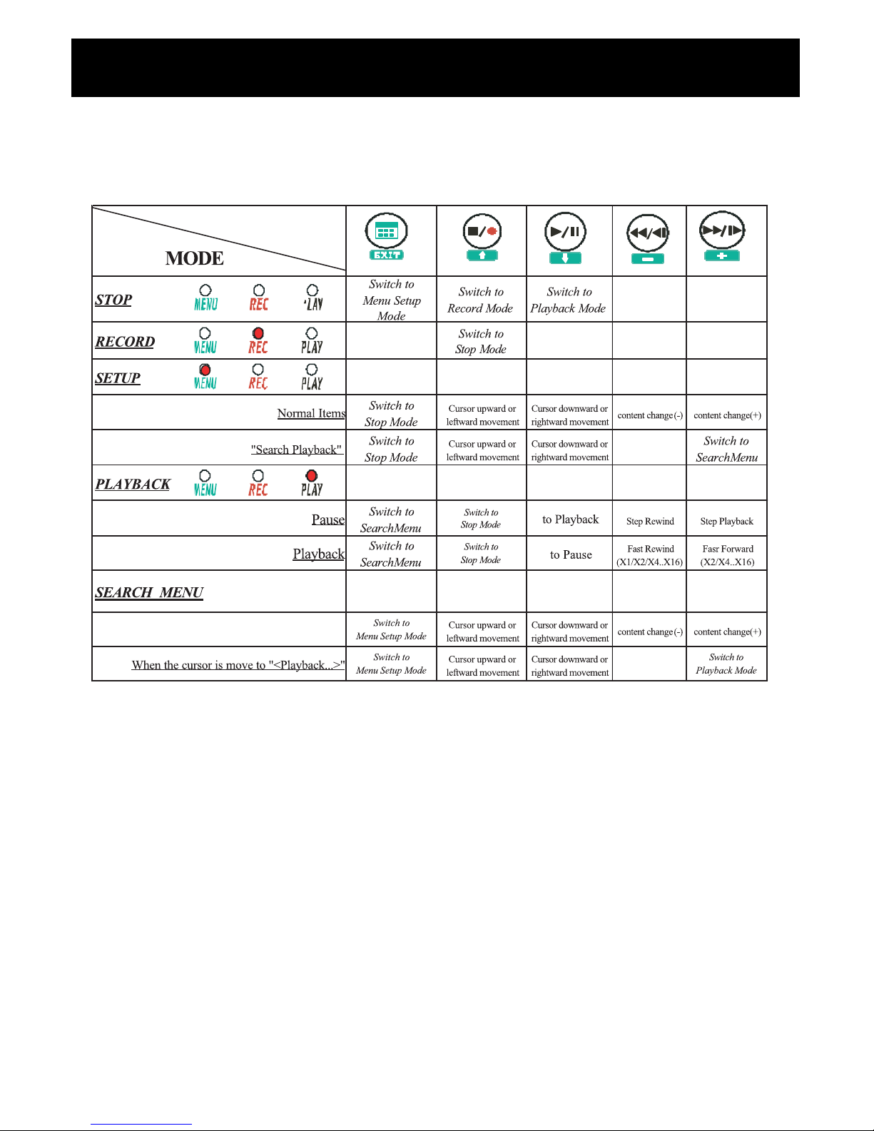
FUNCTIONS
7-1 FUNCTION DESCRIPTION TABLE
It is important to read through and understand the function descriptions before
reading how to operate this system.
The LED light on the front panel indicates the current OPERATION MODE or screen
display status. Under a different mode, each function has different meanings. The
Function Description Table clearly lists the LED light as it appears during different
mode and its corresponding relations with the function buttons.
They system is mainly divided into 5 modes: STOP, RECORD, PLAYBACK, SETUP and
SEARCH MENU. PLAYBACK mode, RECORD mode and SETUP mode may only be
switched to STOP mode but, STOP mode may also be switched to PLAYBACK mode
RECORD mode or SETUP mode. This means that one must switch to STOP mode
before setting up PLAYBACK mode, RECORD mode and SETUP mode.
Under SETUP mode one may switch to SEARCH MENU mode and then to PLAYBACK
mode.
BUTTON

www.svat.com
OPERATION DESCRIPTION 1
POWER ON
Each time immediately after power is restored; they system proceeds with auto
detection and warming up function, and then enters RECORD mode.
RECORD MODE
Under the RECORD mode the system uses two types of recording format:
Continuous Recording and Motion Detection Recording. The recording format
depends on the <RECORD MODE> settings on the SETUP mode. The interval of the
captured frames depends on the <CAPTURE RATE> settings on the SETUP mode.
When recording has been set as continuous recording, for every fixed period of time
the system will automatically record one frame and when recording is set to Motion
Detection recording, for a fixed period of time the system will automatically detect
any changes on the screen (Motion Detection Sensitivity Rate is adjustable according to preference).
When the memory is full and the “Full Stop-Overwrite” switch on the front panel is
switched to “Overwrite”, the memory will be overwritten starting with the oldest data
first, or switch to “Full Stop”, where it will automatically enter STOP mode and not
record any new date.
Under record mode, press << >> button to enter STOP mode.
1) Record Status:
MD-Motion Detection Recording
CNT-Continuous Recording
2) Image Resolution:
640x480
320x240
3) Image Quality: HIGH, MEDIUM and LOW
REC . .
20 04 /04/ 07 12 : 10 :1 0
MD
640x480
/HI 190 93.4%
(4) (5)(1) (2) (3)

www.svat.com
OPERATION DESCRIPTION Cont’d...
4) The screen display shows the recorded images by value of frames.
5) The screen display shows the recorded images by percentage (0% - 100%)
When the memory is full and the “Full Stop-Overwrite” switch on the front panel
is switched to “Overwrite”, the word “LOOP” will be shown.
STOP MODE
Under stop mode, the camera will not proceed to record.When a monitor has been
connected, the user may view images through the monitor.
Under this mode Press <<
•
>> button, to enter RECORD, Press << >> button to enter
PLAYBACK mode, Press <<MENU>> button to enter SETUP mode.
1) Date
2) Time
3) Recorded frames per second
4) System free space; range: 0%-100% When the memory is full (0%) and “Full Stop
Overwrite” switch is switched to “Full Stop”, the word “FULL” will be shown or
switched to “Overwrite”, then the word “LOOP” will be shown.
PLAYBACK MODE
After entering PLAYBACK mode the system automatically playbacks previously
recorded video.
STOP
2004/04 / 07 12:10: 10
190 93 . 4
%
(1) (2)
(3) (4)

www.svat.com
OPERATION DESCRIPTION 1 Cont’d...
• There are two conditions that the system will be switched to PLAYBACK mode:
• Under STOP mode, press << >> button.
• Under SEARCH MENU mode, press <<+>> button
• Under PLAYBACK mode, press << >> button, to enable playback or to pause.
1) Under PLAYBACK mode, press << >> button, to switch the playback forward
speed (X2, X4, X8 and X16). Press << >> button, to switch playback back
ward.
• Under pause status, press << I >> button to proceed with step forward play
back, press << I >> button to proceed with step rewind playback.
• Speed (X1, X2, X4, X8 and X16)
1) Record Date
2) Record Time
3) Playback status:
: Playback
: Fast Forward Playback
: Fast Rewind Playback
II : Pause
4) Record Status:
MD: Motion Detection Record
CNT: Continuous Record
5) Record Resolution:
320x240
640x480
PLAYBACK 2004/ 04 / 07 12 :10:10
x2
`
MD 640x480 /HIGH 10 / 190
(3)
(4)
(5) (6)
(1) (2)
(7) (8)
 Loading...