

Page 1
USER MANUAL
SV 35A
ACOUSTIC CALIBRATOR
Warsaw, March 2017
Copyright © 2017 SVANTEK. All rights reserved.
Page 2

2 SV
35A User Manual
Contents
1. Introduction ........................................................................................................... 3
2. Acoustic calibrator SV 35A ................................................................................... 3
2.1. General description ....................................................................................... 3
2.2. Use of the calibrator ...................................................................................... 5
2.2.1. Automatic calibration ............................................................................... 5
2.2.2. Button functions ...................................................................................... 5
2.2.3. Range diodes .......................................................................................... 6
2.3. Replacing the battery ..................................................................................... 8
3. SV 35A Technical specifications .......................................................................... 9
Page 3
3 SV
35A User Manual
1. Introduction
One of the fundamental questions that are most frequently asked while taking
a measurement is whether its result is accurate. Proceeding with a measurement without
having a positive answer to this question may result in obtaining data of
no practical use and wasting our time. However, we may easily obtain the answer
by performing a calibration of the sound level meter together with the microphone and its
preamplifier. Calibration of the measurement device may be done in two ways: by comparing
the calibrated device with a reference device of known parameters; or using a template of the
measured quantity to perform a reference measurement. Acoustic devices are usually
calibrated in the latter fashion with so-called, acoustic calibrators. Acoustic calibrator is a
device, which produces acoustic pressure of defined level and frequency. In other words, such
calibrator is a reference of acoustic pressure. With help of such a reference we can check the
accuracy of the measurements performed with the sound level meter and/or calibrate it if the
error occurs.
2. Acoustic calibrator SV 35A
2.1. General description
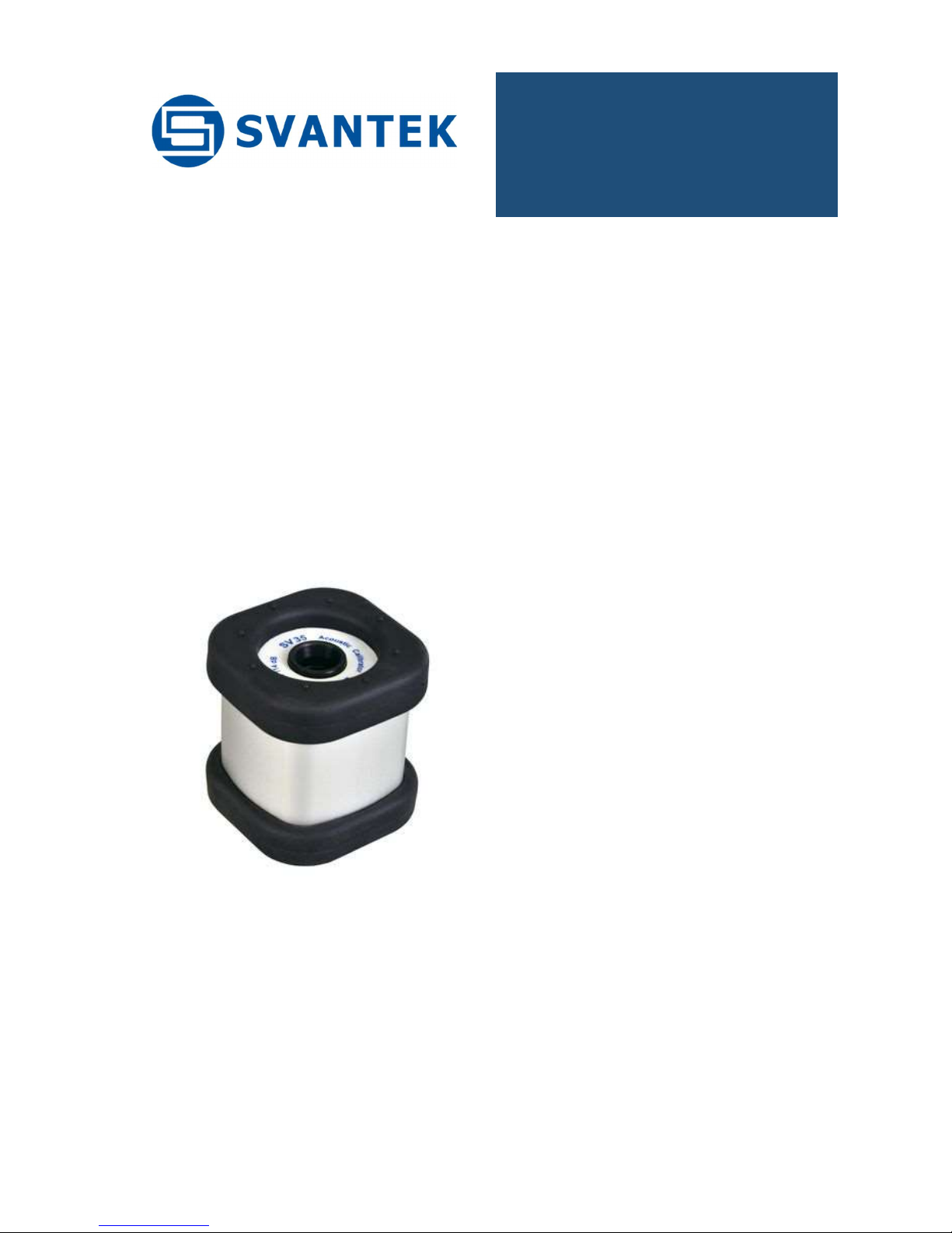
The SV 35A acoustic calibrator is a small, portable dual-range Class 1 device (sound
source), see Picture 1. Powered by two LR03/AAA batteries, it contains
a loudspeaker producing acoustic pressure, reference microphone for monitoring generated
level, pressure and temperature sensors for measurements of atmospheric conditions and a
microprocessor system controlling the operation of the calibrator. Sinusoidal waveform of
1 kHz frequency is digitally generated and feeds the loudspeaker. Sampled signal from the
reference microphone indicates the level of currently generated signal in a feedback loop. On
the basis of information about the level of the signal, actual values of pressure and
temperature, microprocessor adjusts amplification of the loudspeaker signal in order to
produce appropriate sound pressure level in the calibrator’s chamber.
Due to the feedback regulation loop the SV 35A calibrator does not require adjusting and
operates in a wide range of temperatures and humidity (see SV 35A Datasheet).
Picture 1. Acoustic calibrator SV 35A
Page 4
4 SV
35A User Manual
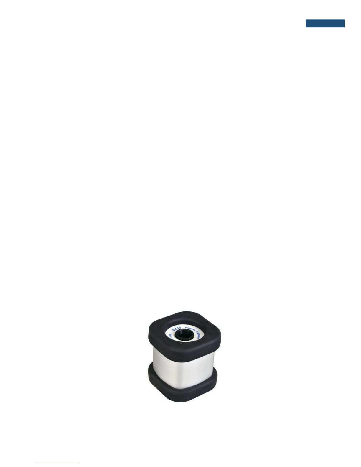
The SV 35A is designed for calibration of sound level meters with ½” and ¼”
microphones. Picture 2 shows the calibration of Class 1 sound level meter SVAN 971 with a
½” microphone.
Picture 2. Calibration of the SVAN 971 sound level meter with a ½” measurement microphone
Notice: For calibration of a meter with a ¼” microphone the SA 30 reduction
adapter must be applied.
Page 5

5 SV
35A User Manual
2.2. Use of the calibrator
2.2.1. Automatic calibration
The SV 35A calibrator is equipped with an optical system which detects the presence of
a microphone in the calibrator’s chamber. That allows the calibrator to be switched on
automatically, when it is placed on the microphone and to be switched off when it is
dismounted. For this reason, usage of the SV 35A calibrator is as simple as putting it on the
microphone, performing the calibration and taking it off the microphone.
. Notice: The SV 35A calibrator will always switch on in the range set at the moment
of switching it off.
. Notice: The automatic switching on will not work when the SA30 calibration
adapter is inserted into the calibrators chamber.
Notice: Default range after replacing the battery is 114 dB.
2.2.2. Button functions
The SV 35A calibrator is equipped with a multifunctional button for controlling operation
of the device. The functions of the button depend on the state of the calibrator (ON/OFF) and
on the time of its pressing (see Table 2).
When the calibrator is OFF, pressing the button turns it on immediately. Range
is automatically set to that one in which the calibrator was switched off. If the calibrator is not
put on the microphone within 3-5 seconds from turning on, it will switch off automatically.
When the calibrator is ON, short pressing of the button (less than 3-5 sec.) will cause
switching the range from 94 dB to 114 dB or the other way round. Button pressed longer (over
3-5 sec.) will switch the calibrator off, either when the device is put on the microphone or not.
Either when the SV 35A is ON or OFF pressing the button over 10 seconds and releasing
it will cause full reset of the system. Normally this function is not necessary. It has been
implemented in the case of inappropriate operation of the calibrator caused by external (EM
radiation, subnormal atmospheric conditions, etc) or internal (inappropriate system reset as a
result of battery replacement) factors.
The operation time of the calibrator with a microphone put inside its chamber
is limited to 3-5 minutes. This functionality was added in order to save the battery, e.g. when
the calibrator is accidentally left with the microphone inside.
Page 6
6 SV
35A User Manual
Notice: Leaving the SA 30 reduction adapter in the chamber of the calibrator is
equivalent with the state of the microphone being left inside. Hence, the calibrator
will switch off automatically after 3-5 minutes from the moment the adapter is put
inside the calibrator.
Table 1. Functional description of the calibrator’s button.
Calibrator turned
OFF
Button press Function description
Short, less than 3 sec. Turn on the device
Over 10 sec. Full reset of the system
Calibrator turned ON
Button press Function description
Short, less than 3 sec. Change the range of the device
Over 3-5 sec. and below 10 sec. Turn off the device
Over 10 sec. Full reset of the system
2.2.3. Range diodes
In normal mode of operation, the calibrator’s diodes act as range indicators. In this mode
diode of the chosen range is lighting with continuous light, indicating that the device is ready
for to start the calibration procedure (see Picture 4).
After the calibrator is put on the microphone, switched on or the range is changed,
acoustic pressure inside the calibrator’s chamber is adjusted to the desired level. During that
process appropriate range diode blinks with a frequency of 2 Hz.
Notice: Calibration should not be performed until the range diode is lighting with
continuous light.
Page 7

7 SV
35A User Manual
Warning: In the case of water condensation inside calibrator SV 33A can
generate significantly lower acoustic pressure then specified. Condensation
can appear when cold device is moved to the warmer environment. In such
a case certain acclimatization time is required.
For the room temperature environment (ca. 20 deg C) the recommended
acclimatization time is approximately as follows:
30 minutes for the initial calibrator temperature -10 deg C
15 minutes for the initial calibrator temperature 0 deg C
2 minutes for the initial calibrator temperature +10 deg C
Before reaching acclimatization time SV33A cannot be used as a reference
sound source!
Picture 4. The top view of the SV 35A calibrator with one diode on
The diodes blinking alternately indicate the low voltage of the battery. It is recommended
to not use the SV 35A calibrator in this state as the generated level may differ from the declared
values.
Notice: Replace the batteries, when diodes blink alternately.
Page 8

8 SV
35A User Manual
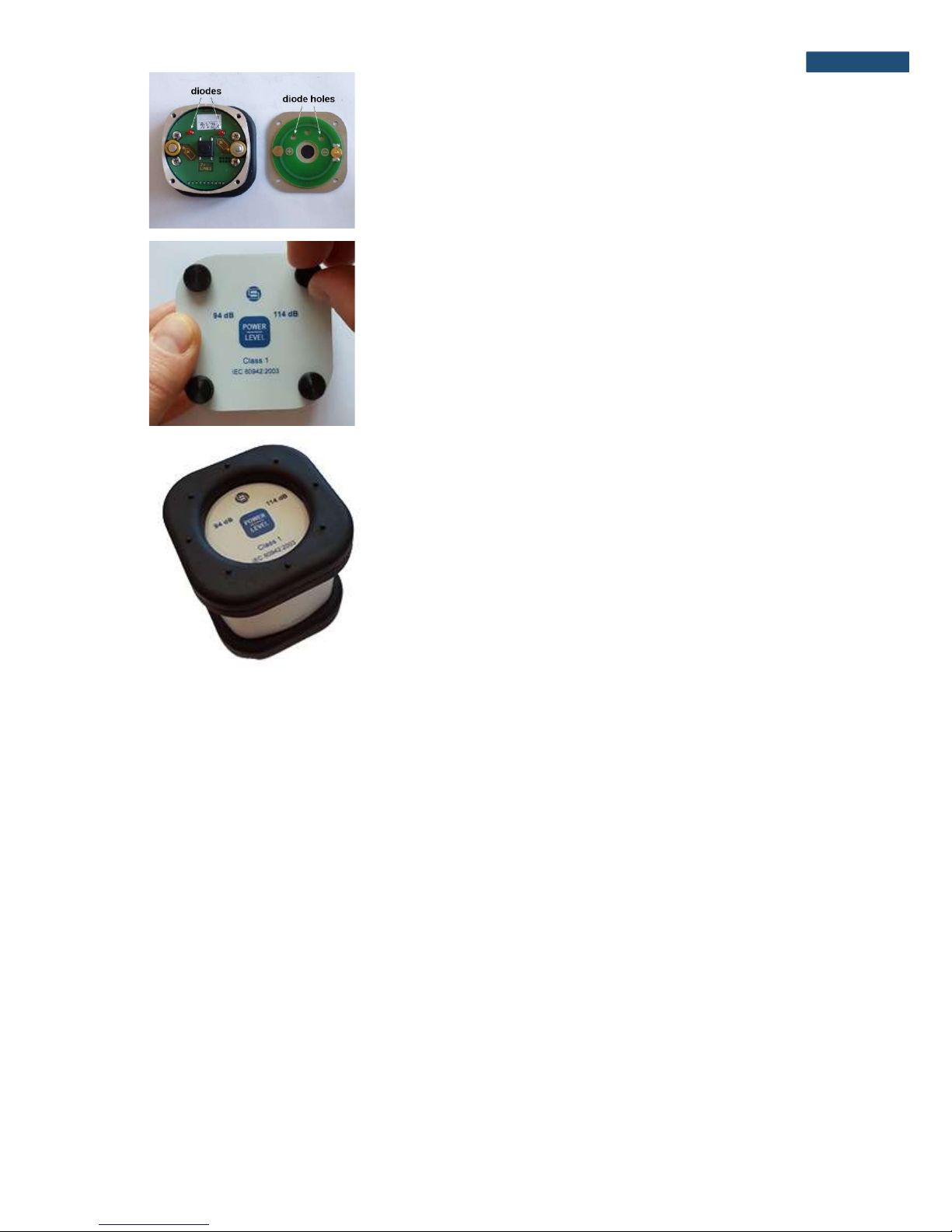
2.3. Replacing the battery
The battery should be replaced as follows:
a) remove the rubber cover on the button and diodes’ side
b) holding the cover unscrew four fixing screws with your
fingers
c) take off the cover and remove discharged batteries
d) put new batteries in place of the discharged ones with
polarization as indicated on the printed board and
calibrator’s case
Page 9
9 SV
35A User Manual
e) put on the cover so that the diodes fit the corresponding
holes in it
f) holding the cover with one hand fasten the fixing screws
g) put on the rubber cover
3. SV 35A Technical specifications
Output signal
Sound Pressure Level (SPL): 94 dB and 114 dB, with respect to 20 Pa in reference
conditions
Accuracy: IEC 60942: 2003 standard, Class 1
SPL Accuracy: 0.3 dB
Frequency accuracy: 0.2 %
Total Distortion < 0.25 % for 94 dB range and
< 0.75 % for 114 dB range
Reference conditions
Temperature: 23 C
Atmospheric pressure: 101.3 kPa
Humidity: 30-80 % RH
Effective microphone load volume: 250 mm3, microphone type: 4134, SN: 1591010
Page 10

10 SV
35A User Manual
General data
Effective load volume sensitivity: 0.00027 dB / mm3
Level stabilization time: typical 10 sec., max. 25 sec.
Microphone dimensions: ½” and ¼” with reduction adapter SA 30
Storage temperature range: -25 C do + 70 C
CE classification: EN 61010-1: 2010
EN 61326-1:2006
EN 55022:2010
EN 60942:2003
Working conditions
Temperature range: from –10 C to +50 C
Atmospheric pressure range: from 65 kPa to 108 kPa
Humidity range: from 25 % to 90 % RH
Environmental conditions influence (typical)
Temperature coefficient: 5·10-3 dB/C
Pressure coefficient: 1·10-4 dB/hPa
Humidity coefficient: 1.25·10-3 dB/%
Power supply
Battery type: two LR03 (IEC)/AAA (ANSI) alkaline batteries
Continuous operation time: 40 hours in 94 dB range and
30 hours in 114 dB range
Standby mode: approx. 2 years
Minimal working voltage: 2.1 V
Dimensions and weight
Weight: 305 g with batteries
Dimensions: 65 x 65 x 70 mm
 Loading...