

Page 1
USER MANUAL
SV 200A
NOISE MONITORING
STATION
Warsaw, 2019-07-02
Rev. 1.05
Copyright © 2019 SVANTEK.
All rights reserved.
Page 2
2
SV 200A User Manual
Note: Because of continuous product improvement SVANTEK reserves the right to make
changes to product specifications without notice. To download the most up to date user's
manual please visit our web site at www.svantek.com. This user’s manual presents the
firmware revision named 1.04.3 (see the Unit Label review to check version details).
The succeeding software revisions (marked with the higher numbers) can change the view of
some displays presented in the text of the manual.
WEEE Notice: Do not throw the device away with the unsorted municipal waste at the end of its
life. Instead, hand it in at an official collection point for recycling. By doing this you will help to preserve
the environment.
The software described in this manual is furnished under a license agreement and may be used only in
accordance with the terms of that agreement.
Copyright Notice
Copyright © 2019 Svantek Sp. z o.o.
All rights reserved.
Reproduction without permission is prohibited.
Trademarks
Trademarks or registered marks in this manual belong to their respective manufacturers.
Microsoft and Windows are registered trademarks of Microsoft Corporation.
The Bluetooth
®
1
word mark and logos are registered trademarks owned by Bluetooth SIG, Inc.
Disclaimer
Information in this document is subject to change without notice and does not represent a commitment
on the part of Svantek.
Svantek provides this document “as is,” without warranty of any kind, either expressed or implied,
including, but not limited to, its particular purpose. Svantek reserves the right to make improvements
and/or changes to this manual, or to the products and/or the programs described in this manual, at any
time.
Information provided in this manual is intended to be accurate and reliable. However, Svantek assumes
no responsibility for its use, or for any infringements on the rights of third parties that may result from its
use.
This product might include unintentional technical or typographical errors. Changes are periodically
made to the information herein to correct such errors, and these changes are incorporated into new
editions of the publication.
Technical Support Contact Information:
web: www.svantek.com
e-mail: office@svantek.com.pl
1
“The Bluetooth
®
word mark and logos are registered trademarks owned by Bluetooth SIG, Inc. and any use of such marks by SVANTEK is
under license. Other trademarks and trade names are those of their respective owners.
Page 3

3
SV 200A User Manual
IMPORTANT NOTES BEFORE USE
✓ While connecting your SV 200A to a PC by the SC 256A cable, first insert the lemo plug into the
instrument’s MULT. I/O socket and then the USB plug into the PC!
✓ Monitoring station should not be stored for a long time with discharged Li-Ion batteries. Storing with
batteries in discharged condition may damage them. If so, warranty for Li-Ion battery is void.
✓ If Monitoring station is planned to be stored for a long period of time, it is recommended to charge
its battery to 60% capacity. The battery should be charged at least once per 6 months.
✓ Before installing the station at the measurement site, make sure that the protective caps on the four
anti-bird spikes are removed. It is recommended to use the protective caps during transportation
and storage or other operations with the instrument like, laboratory calibration, etc. to avoid
personal injury.
✓ Tripod or pole with 3/8” thread is not recommended for permanent installation.
✓ The windscreen influences the free-field characteristics of the instrument, therefore it is important
to check its condition regularly. In the case of visible degradation of the foam surface it must be
replaced by the new one.
✓ Even though the SB 274 power supply unit has a high IP index (Ingress Protection), it is still not
recommended to leave it on the ground for safety reasons. Good practice is to mount it on the pole
or mast.
✓ While opening the control panel flap the coin-operated screw should be loosened using, for
example, a coin and then unscrewed with fingers until it stops. Opening the flap with the screw left
in the intermediate position may damage the varnish of the casing.
✓ Maximum sound pressure level that can affect the microphone without destroying its membrane is
146 dB.
Page 4

4
SV 200A User Manual
CONTENTS
IMPORTANT NOTES BEFORE USE ..................................................................................................3
1 INTRODUCTION ....................................................................................................................... 11
1.1 Sound Level Meter & Analyzer features ............................................................................. 11
1.2 General features of SV 200A ............................................................................................. 12
1.3 Accessories included ......................................................................................................... 12
1.4 Accessories available (optional) ......................................................................................... 12
1.4.1 SV 36 – Class 1 Sound Calibrator .................................................................................. 13
1.4.2 SB 276 - solar panel ...................................................................................................... 13
1.4.3 SA 206 – telescopic mast ............................................................................................... 13
1.4.4 SP 275 - weather station ................................................................................................ 14
1.4.5 SP 272 – alarm lamp ..................................................................................................... 14
2 ASSEMBLING THE INSTRUMENT........................................................................................... 15
2.1 Recommended order of assembly ...................................................................................... 15
2.2 Delivered kit ....................................................................................................................... 15
2.3 Pre-assembling .................................................................................................................. 17
2.4 Mounting ........................................................................................................................... 21
2.4.1 Mounting SV 200A on the mast ...................................................................................... 21
2.4.2 Mounting on 3/8” thread ................................................................................................. 24
2.4.3 Mounting the SV200A station on the mast aligning to the North ...................................... 24
2.5 Anti-theft protection ............................................................................................................ 25
2.6 Windscreen protection ....................................................................................................... 25
2.7 Power supply unit .............................................................................................................. 25
2.8 Assembling the SP 275 weather station on the mast (optionally) ........................................ 26
2.9 Finishing ............................................................................................................................ 26
3 SV 200A CONNECTORS AND CONTROL PANELS ................................................................ 27
3.1 Connectors panel .............................................................................................................. 27
3.1.1 SIM card slot .................................................................................................................. 27
3.1.2 DC IN socket ................................................................................................................. 27
3.1.3 External Communication Interface socket ....................................................................... 28
3.1.4 LAN socket .................................................................................................................... 28
3.1.5 Antenna sockets ............................................................................................................ 28
3.2 Control panel ..................................................................................................................... 28
4 CALIBRATION ......................................................................................................................... 30
4.1 Preparation for calibration .................................................................................................. 30
4.2 Automatic Calibration ......................................................................................................... 33
4.3 Calibration with the use of the control panel ....................................................................... 34
Page 5

5
SV 200A User Manual
4.4 Calibration with the use of SvanPC++ and USB connection ............................................... 35
4.5 System check with the use of electrostatic actuator ............................................................ 36
5 OPTIONS OF THE STATION CONTROL .................................................................................. 38
5.1 SV 200A manual control via Control panel ......................................................................... 38
5.1.1 Measurement results viewing ......................................................................................... 38
5.1.2 Configuration Menu........................................................................................................ 41
5.2 SV 200A remote control via SvanNET Web-service ........................................................... 45
5.3 SV 200A remote control via SvanPC++_RC program ......................................................... 46
6 REMOTE COMMUNICATION ................................................................................................... 47
6.1 Main communication channel ............................................................................................. 47
6.2 SMS / E-mail alarming ....................................................................................................... 47
6.3 Interface capabilities of 3G modem .................................................................................... 48
6.4 Interface capabilities of WLAN/LAN module ....................................................................... 48
6.5 Interface capabilities of Bluetooth module .......................................................................... 48
7 CONFIGURATION OF THE REMOTE CONNECTION – SVANNET APP .................................. 49
7.1 Configuration of the SV 200A connections ......................................................................... 50
7.1.1 Remote Communication Settings ................................................................................... 51
7.2 SV 200A System Check ..................................................................................................... 53
7.3 Icons of SVANNET APP .................................................................................................... 53
7.4 Advanced Mode ................................................................................................................. 54
7.5 Other options ..................................................................................................................... 55
8 SVANNET WEB-SERVICE ....................................................................................................... 56
8.1 Station list view .................................................................................................................. 56
8.1.1 STATUS view ................................................................................................................ 58
8.1.2 LOG views ..................................................................................................................... 60
8.2 WEB INTERFACE view ..................................................................................................... 61
8.2.1 Live data view ................................................................................................................ 61
8.3 Status view ........................................................................................................................ 64
8.4 Storage view ...................................................................................................................... 65
8.4.1 Configuration views........................................................................................................ 66
8.4.2 FIRMWARE UPGRADE tab ........................................................................................... 78
9 SVANPC++ SOFTWARE .......................................................................................................... 79
9.1 SvanPC++ software installation and activation ................................................................... 79
9.2 SV 200A control via USB interface ..................................................................................... 79
9.3 Configuring wireless connection ......................................................................................... 80
9.3.1 Connections via 3G modem ........................................................................................... 82
9.4 Connecting to the station ................................................................................................... 82
9.5 Starting measurements ................................................................ ...................................... 83
Page 6

6
SV 200A User Manual
9.6 Viewing live results ............................................................................................................ 84
9.7 Changing the working directory .......................................................................................... 85
9.8 Station configuration .......................................................................................................... 86
9.8.1 General settings ............................................................................................................. 87
9.8.2 Measurement setup ....................................................................................................... 87
9.8.3 Channels ....................................................................................................................... 89
9.8.4 Logger settings .............................................................................................................. 90
9.8.5 Event recording.............................................................................................................. 92
9.8.6 CSV export .................................................................................................................... 93
9.8.7 Advanced settings.......................................................................................................... 95
9.8.8 External I/O.................................................................................................................... 95
9.8.9 Remote communication ................................................................................................. 96
9.8.10 Time synchronization ................................................................................................. 97
9.8.11 Calibration & System Check ....................................................................................... 98
9.8.12 Alarm settings ............................................................................................................ 99
9.9 Data collecting ................................................................................................................. 104
9.9.1 Start working with Remote Communication Center ....................................................... 105
9.9.2 Remote Communication Service .................................................................................. 106
9.9.3 SVAN Files .................................................................................................................. 107
9.9.4 Automatic Files Downloading ....................................................................................... 109
9.9.5 Continuous Logger Download ...................................................................................... 112
9.9.6 Live Results ................................................................................................ ................. 114
9.9.7 Alarms ......................................................................................................................... 116
10 NOISE SOURCE DIRECTION DETERMINATION ................................................................... 117
11 INSTRUMENT UPGRADE ................................ ................................................................ ...... 119
11.1 Instrument upgrade via USB cable ................................................................................... 119
11.2 Firmware upgrade via SvanNET Web-service .................................................................. 119
12 MAINTENANCE ...................................................................................................................... 121
12.1 Transportation and storage .............................................................................................. 121
12.2 Cleaning .......................................................................................................................... 121
12.3 Resetting the instrument .................................................................................................. 121
12.4 Troubleshooting ............................................................................................................... 121
Appendix A. REMOTE CONTROL (firmware revision 1.x.x)................................................... 123
Appendix B. DATA FILE STRUCTURES ................................................................................. 124
B.1 General structure of the SVL file ...................................................................................... 124
B.2 Records in the SVL logger file .......................................................................................... 138
B.2.1 Record with the results................................................................................................. 138
B.2.2 Record with the state of the markers ............................................................................ 139
Page 7

7
SV 200A User Manual
B.2.3 Record with the breaks in the results registration .......................................................... 139
B.2.4 Record with the breaks account PAUSE in the results registration ................................ 140
B.2.5 Record with the wave file name .................................................................................... 140
B.2.6 Record with Summary Results ..................................................................................... 140
B.2.7 Record with audio data ................................................................................................ 141
B.2.8 Record with the meteo data ......................................................................................... 141
B.2.9 Record with system check data .................................................................................... 142
B.2.10 Record with remote marker data .............................................................................. 142
B.2.11 Record with the state of the alarm markers ............................................................... 143
B.2.12 Record with the directivity results ............................................................................. 143
B.2.13 Record with GPS data .............................................................................................. 144
B.3 Structure of the CSV file .................................................................................................. 145
B.4 Structure of the SVT file ................................................................................................... 145
B.5 Structure of the SVA file ................................................................................................... 145
B.6 Structure of the TXT file ................................................................................................... 145
B.7 Structure of the LOG file .................................................................................................. 145
B.8 Date and time .................................................................................................................. 145
Appendix C. TECHNICAL SPECIFICATIONS .......................................................................... 146
C.1 Specification of SV 200A in the standard configuration ..................................................... 146
C.2 Specification of the SV 200A 1/1 and 1/3 OCTAVE analysis ............................................. 174
C.3 Frequency characteristics of the implemented broadband digital filters ............................. 183
C.4 Miscellaneous specification of SV 200A ........................................................................... 185
Appendix D. DEFINITIONS AND FORMULAE OF MEASURED VALUES ............................... 194
D.1 Basic terms and definitions .............................................................................................. 194
D.2 Definitions and formulas of the SLM results...................................................................... 195
D.3 Statistical levels – Lnn definition ...................................................................................... 198
Page 8

8
SV 200A User Manual
INDEX
1
1/1 Octave · 41
1/3 Octave · 41
3
3G modem · 44, 48
A
Accessories · 12
Action · 75
Actuator · 32, 36
Advanced alarm configuration · 99
AFD · 109
Airport · 89
Airport filter · 44
Alarm lamp · 14
Alarms · 47, 99, 116
Antenna · 20, 28
Anti-bird spikes · 15, 19
Anti-theft · 25
APN · 45, 51, 82
Audio · 75
Audio recording · 70
Auto calibration · 33, 43, 76
Auto Rotate · 44
Automatic calibration · 98
Automatic system check · 99
Auxiliary Setup · 45
B
Basic view · 39
Bluetooth · 44, 48
Bootstrap · 119
By Measurement · 34, 42
C
Calibration · 30, 34, 35, 42, 76, 98
Calibration factor · 33, 34, 35
Calibration level · 33, 34
Channels · 89
Charging · 39
CLD · 112
Communication · 40
Compensation Filter · 44
Con nozzle · 30
Configuration · 66
Connection status · 40
Connector panel · 27
Continuous trigger · 93
Control keys · 29
Control panel · 28, 38
CSV export · 68, 93
D
Data transfer log · 60
DC IN · 27
Deleting files · 109
Detector · 43, 66, 90
Display · 28, 44
Downloading files · 108
E
E-mail Alarm · 76
Environment · 89
Event · 71
Event recording · 92
Events · 70
Exponential · 66, 89
Extension sleeve · 19, 30, 31
External DC source · 27
External I/O · 95
F
Factory Settings · 45
Fast · 43, 90
Filter · 43, 67, 90
Firmware · 119
Firmware upgrade · 78
Function · 41
G
General settings · 43, 87
GPS · 78
Gradient + trigger · 93
H
Hardboot · 119
Page 9

9
SV 200A User Manual
I
I/O Alarm · 75
Icons · 39, 53, 57
Impulse · 43, 90
Instantaneous result · 62
Instrument · 44
Instrument clock · 66
Instrument wizard · 35, 79
Integration Period · 43, 68, 89
Integration period trigger · 93
Interface · 40
L
LAN · 28, 44, 48
LAN Network · 52
Language · 45
Large view · 39
LEQ Integration · 43
Level - trigger · 93
Level + trigger · 93
Level Meter · 41
Linear · 43, 66, 89
Live Results · 84, 114
Location name · 78
Logger meteo · 91
Logger results · 92
Logger settings · 90
Logger splitting · 68
Logger step · 91
M
Maintenance · 121, 123, 124
Manual calibration · 34
Marker · 75
Measurement · 43
Measurement function · 66, 88
Measurement Function · 41
Measurement setup · 87
Menu · 41
Meteo · 73
Microphone · 15, 17
Microphone protective sleeve · 15, 30, 32
Mobile Network · 51
MULT. I/O · 28
O
Outdoor filter · 89
P
Power supply · 25, 27
Power Supply view · 40
Pre-assembling · 17
Profiles · 43, 89
Project name · 78
Protective cup · 17
R
Recording trigger · 93
Recording type · 92
Remote communication · 96
Remote Communication Center · 80
Remote Connection Wizard · 82
Remote control · 45, 46
Repetition cycles · 43, 89
Reset · 121
RMS Integration · 66, 89
RTC · 44
Running SPL · 39
S
Sampling frequency · 70
Screen Off · 44
Signal level · 40
SIM card · 27
Slope -– trigger · 93
Slope + trigger · 93
Slow · 43, 90
SMS Alarm · 75
Solar panel · 13, 27
Sound analyzer · 11
Sound calibrator · 13, 32
Sound level meter · 11
Spectrum · 43
Spectrum view · 40
Splitting Mode · 92
Start delay · 43, 88
Station configuration · 86
Station name · 78
Statistics · 68
Step · 68
Storage · 65, 67
SVAN Files · 107
SvanNET · 45, 56
Svannet App · 49
SvanPC++ · 79
System · 74
System check · 36, 42, 53, 76
System Check · 98
Page 10

10
SV 200A User Manual
T
TCP/IP · 47
Telescopic mast · 13
Threshold · 72
Time synchronization · 97
Traffic · 40
U
Unit Label · 45
Updating RTC · 109
Upgrading · 119
Uploading files · 108
USB · 44
V
Vertical view · 39
View mode · 38
W
Wave · 70
Wave recording · 92
Weather station · 14, 26
Windscreen · 19, 25, 30
Wireless · 44
WLAN · 44, 48
WLAN Access Point · 54, 55
WLAN Infrastructure · 51
Working directory · 85
Page 11

11
SV 200A User Manual
1 INTRODUCTION
The SV 200A is a unique Noise Monitoring Terminal (NMT) which includes in
a single portable housing: outdoor microphone, sound level meter and 1/1 &
1/3-octave analyser, advanced logger, sound direction detector and
communication systems (3G modem, Bluetooth, LAN and WLAN). This
system can be easily transported and installed by one person in the field
conditions.
The instrument is an ideal choice for an unattended permanent and semipermanent environmental noise and weather monitoring. Instrument can be
used for community and airport noise monitoring.
The system enables easy communication, data download and configuration
using PC or mobile device over the Internet or local network.
SV 200A meets Class 1 requirements of IEC 61672-1:2013 standard and
provides broad band results with all required weighting filters, 1/1 octave &
1/3-octave spectra with complete statistical analysis.
Instrument can be easily calibrated in-field using sound calibrator. Built-in
electrostatic actuator can be activated remotely or periodically in automated
mode for self-testing.
SV 200A enables great logging capability which includes time history of broad
band results and spectra with two selectable logging steps down to
2 milliseconds and audio recording on trigger of different types. Data are stored
in the instrument’s memory and can be transferred over the internet on demand
or in automatic mode.
Remote communication option for the SvanPC++ software and the SvanNET
web-server provides advanced communication with files downloading, data
visualization and measurement results exporting. Environmental monitoring
option for the SvanPC++ software is dedicated for measurement data
management, advanced data processing, analysis, visualization and reporting.
Thanks to robust casing, protection against overheating & humidity
condensation, built-in rechargeable battery, this instrument is excellent for
permanent installation in all environmental conditions.
Thanks to four MEMS microphones built into the body of SV 200A you can
detect the source of the dominant energy occurs in two planes - horizontal "XY"
and vertical "Z".
1.1 SOUND LEVEL METER & ANALYZER FEATURES
• noise measurements: SPL, Leq, SEL, Lden, Ltm3, Ltm5, Lpeak, Lmax, Lmin and LEPd
• statistics: Lnn (L1 ÷ L99), complete histogram in meter mode and 1/1 & 1/3 octave analysis
• class 1 accuracy in the frequency range 3.5 Hz – 20 kHz and with 48 kHz sampling rate
• total dynamic measurement range: 25 dBA LEQ ÷ 133 dB PEAK
• dynamic range: 115 dB
• parallel Impulse, Fast and Slow detectors for measurements with A, C, B or Z weighting filters
• software selectable community and airport direction characteristics
• digital True RMS detector with peak detection, resolution 0.1 dB
• 1/1 octave real-time analysis meeting class 1 requirements of IEC 61260-1:2014, frequencies from
31.5 Hz to 16 kHz
• 1/3 octave real-time analysis meeting Class 1 requirements of IEC 61260-1:2014, frequencies from
20 Hz to 20 kHz
• audio signal recording to logger files or separate wav format files on demand with selectable
sampling frequency and recording period
Page 12

12
SV 200A User Manual
1.2 GENERAL FEATURES OF SV 200A
• Noise monitoring terminal fitted in one portable instrument dedicated for unattended permanent and
short period noise monitoring
• Integrated, non-removable microphone preamplifier
• Noise measurements meeting IEC 61672-1:2013, class 1 standard
• 1/1 & 1/3 octave real-time analysis
• Audio events and wave recording
• AAC audio compression (future option)
• Statistical analysis with up to 10 percentile values
• Community and airport direction characteristics, software selectable
• Remote, automated system check (built-in acoustic actuator)
• Built-in 16 GB memory
• High efficiency windscreen
• Designed for outdoor use in all weather conditions
• Communication over 3G and WLAN/LAN networks
• GPS module
• Bluetooth module
• eCompass sensor
• Vaisala WXT5xx weather monitoring module support
• Easy connection configuration by means of SVANNET APP software
• Easy remote access over PC or Smartphone by means of SvanNET Web service
• Precise time synchronization and GPS position of the instrument
• Up to 6 days of autonomy operation (internal battery operating time with all radio modules off)
• Advanced software for data processing and reporting SvanPC++_EM
• Li-Ion 72.4 Wh rechargeable battery (non-removable)
• Direct connection of solar panel (without controller) or DC power supply
• Robust design
• Ingress Protection Rating IP 65
• Easy and fast installation in-field
• Directivity of dominant sound source detection
1.3 ACCESSORIES INCLUDED
• MK 255S Microtech Gefell, 50 mV/Pa, prepolarised ½” condenser microphone
• SB 274 waterproof external DC power supply
• SA 209 5” foam windscreen
• SC 256A USB cable
• ST 200A 4 microphones for noise direction measurements
• Anti-bird spikes
• Extension and microphone protective sleeves
• GSM and WLAN antennas
• Mounting kit
• SvanPC++_RC – Remote Communication module for SvanPC++ software (single license)
1.4 ACCESSORIES AVAILABLE (OPTIONAL)
• SV 36 Class 1 Sound Calibrator 94/114 dB @ 1000 Hz
• SB 276 solar panel
• SA 206 4 m telescopic mast
• SP 275 weather station based on Vaisala WXT53x module
• SC 209A dedicated cable for the SP 275 weather station
• SP 272 alarm lamp
• SP 200 LAN adapter
• SvanPC++_EM Environmental monitoring module for SvanPC++ software (single license)
Page 13
13
SV 200A User Manual
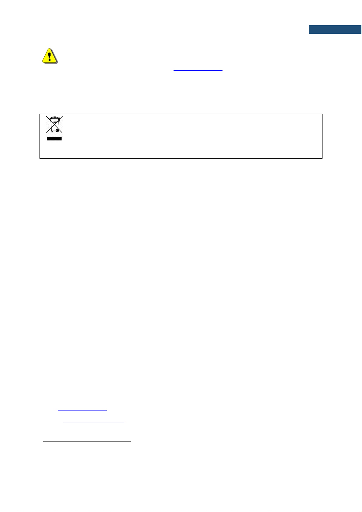
1.4.1 SV 36 – Class 1 Sound Calibrator
For results verification purposes, most norms and standards impose the
requirement to calibrate the measurement channel before and after each
measurement or measurement session.
A sound calibrator is a device which produces an acoustic pressure of
defined level and frequency.
SV 36 sound calibrator produces an acoustic pressure of defined level
94/114 dB at a frequency of 1 kHz.
1.4.2 SB 276 - solar panel
The SB 276 solar panel (40 W, 17.5 V) extends the working time of the
monitoring station. Size and weight of the panel enables easy
transportation in the dedicated carrying bag.
SB 276 does not require additional batteries or external controllers.
SB 276 is equipped with a military standard connector cable for direct
connection to the monitoring station.
1.4.3 SA 206 – telescopic mast
The SA 206 is a Manfrotto 269BU mast with adjustable height from 1.5
meter to 4 meters.
Page 14
14
SV 200A User Manual
1.4.4 SP 275 - weather station
SP 275 is a Vaisala Weather Transmitter WXT5xx type meteorological
station used optionally with the SV 200A monitoring station. It is
connected to SV 200A via serial RS 232C interface.
SP 275 measures 6 most essential weather parameters (barometric
pressure, humidity, precipitation, temperature, wind speed and direction)
and also rain and hail intensity. It is compact and light-weight, has no
moving parts, has internal heating and can be easily installed with a onebolt mounting method.
SP 275 has an automatic control circuit that switches the heating on at
low temperatures.
Five measurement weather parameters (barometric pressure, humidity,
temperature, wind speed and direction) are transferred from the SP 275
to the monitoring station every second.
Precipitation and 3 values for rain and hail (intensity, accumulation and
duration) are transferred, every 10 seconds, only when it is raining or
hailing.
SV 200A may save them in the logger file as a Summary Results with
the Integration Period step and as a time-history results with the
Logger Step (see Chapters 9.8.2 and 9.8.4).
You may switch on or off recording of the Meteo results in the logger file
through the SvanPC++ program (see Chapter 9.8.4).
Note: See also Vaisala WXT5xx User Guide.
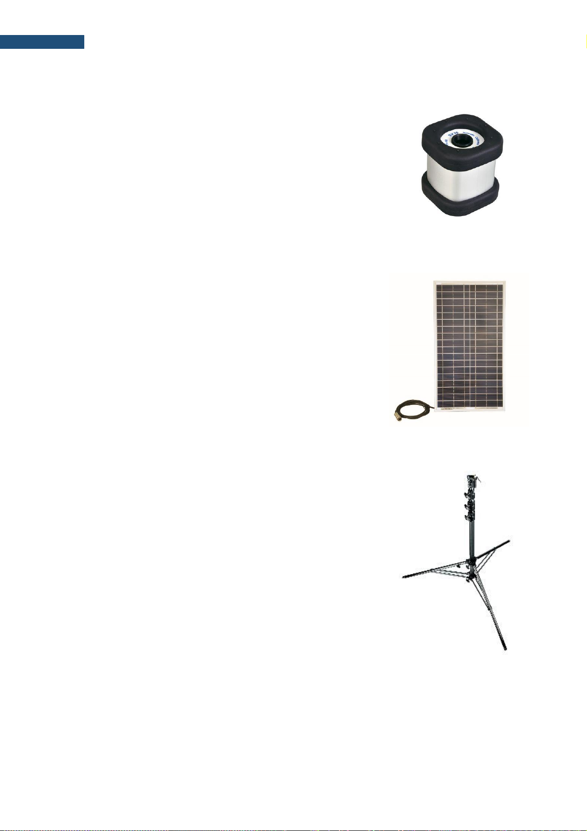
1.4.5 SP 272 – alarm lamp
SP 272 is a type WERMA, LED/Buzzer alarm lamp (12V DC).
The alarm lamp is connecting to the EXTERNAL INTERFACE connector
instead of the Meteo module.
In this lamp, the buzzer is disabled by default. To enable it:
1. open the case by pushing the black button and turning the plafond
and
2. shift the switch to the left.
1
2
Page 15
15
SV 200A User Manual
2 ASSEMBLING THE INSTRUMENT
2.1 RECOMMENDED ORDER OF ASSEMBLY
After unpacking, check the completeness of the set according to Chapter 2.2.
Note: It is advised to read Chapters 2.3 to 2.9 of the User Manual carefully before assembling.
Recommended order of installation:
1. pre-assembling of the SV 200A (see Chapter 2.3),
2. mounting the SV 200A (see Chapter 2.4),
3. power supply installation (see Chapter 2.7),
4. optional meteorological station installation (see Chapter 2.8),
5. arrangement of the cabling (see Chapter 2.9).
2.2 DELIVERED KIT
The kit delivered to the client consists of the following elements:
1. the SV 200A instrument includes next
permanently integrated elements:
• integrated, non-removable
microphone preamplifier
• built-in electrostatic actuator
triggered manually or in automatic
mode
• Li-Ion rechargeable battery
• 16 GB micro SD card
• 3G modem
• WLAN module
• Bluetooth module
• eCompass sensor
• GPS receiver
• control panel
• 4 x MEMS microphones.
2. and elements that can be
disconnected:
• Microtech Gefell MK 255S,
50 mV/Pa, prepolarised ½”
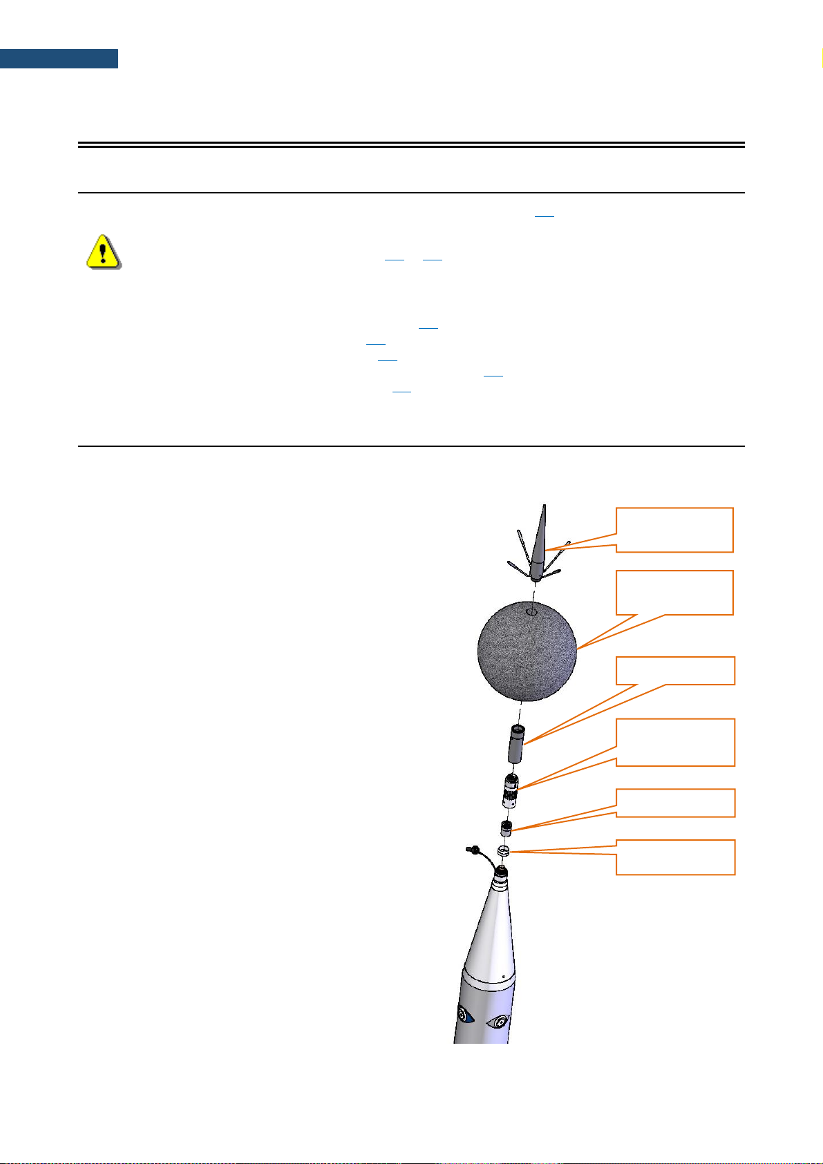
condenser microphone
• top cone with anti-bird spikes
• microphone extension sleeve
• microphone protective sleeve
• microphone sealing hood
• SA209 5” foam windscreen
• 3G antenna
• WLAN antenna
top cone with
anti-bird spikes
SA209 foam
windscreen
extension sleeve
microphone
protective sleeve
microphone
sealing hood
Page 16
16
SV 200A User Manual
3. SC 256A cable to communicate with
SV 200A using USB interface
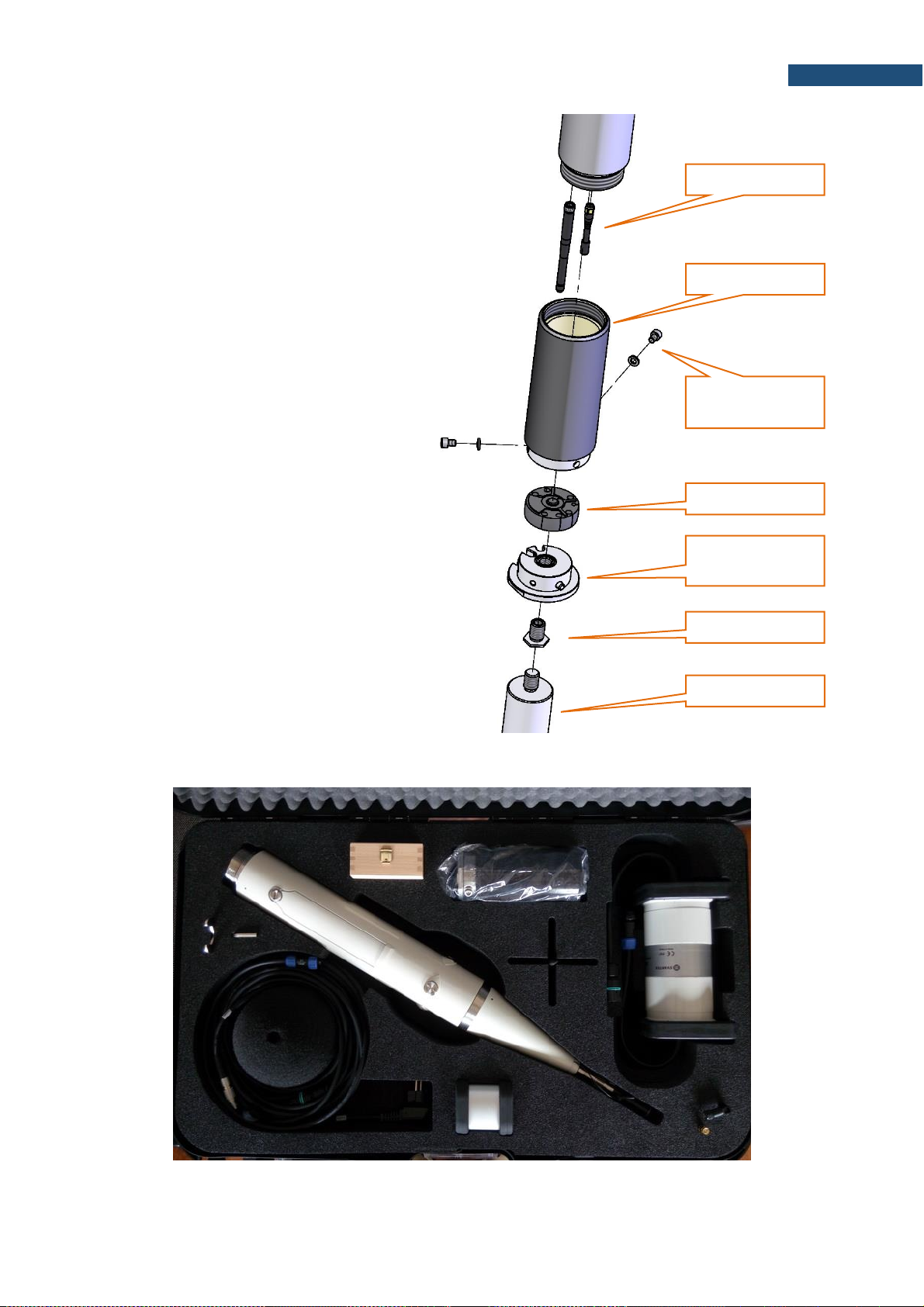
4. axial mounting kit:
• mounting sleeve
• silicon seal
• base of the sleeve
• two bolts M6x12 with spring
washers
• M14/3/8” adapter
5. set of tools:
• special ring spanner 22mm
• Allen key 3mm
• Allen key 5mm
6. DC power supply kit:
• weatherproof DC power unit of the
type SB 274
• set of 4 dowels Φ 10 mm (with
screws) for mounting the power
unit onto a wall
• 2 band clips for mounting of the
power supply on a mast
The instrument kit is delivered in the special case, which is dedicated also for storage and transportation of
the instrument.
base of the sleeve
M14/
3/8
” adapter
two bolts M6x12
with washers
mounting sleeve
antennas
tip of the mast
silicon seal
Page 17
17
SV 200A User Manual
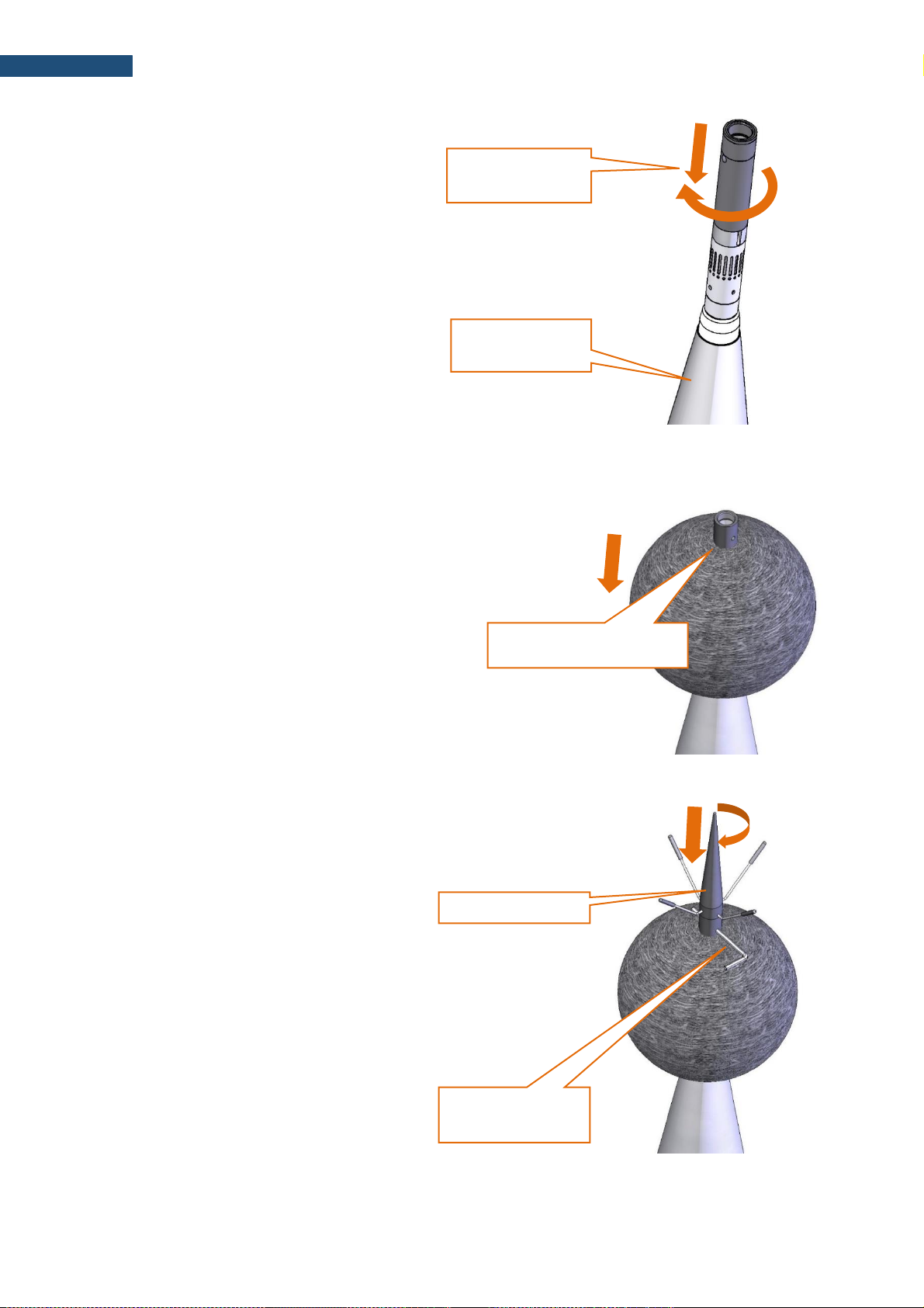
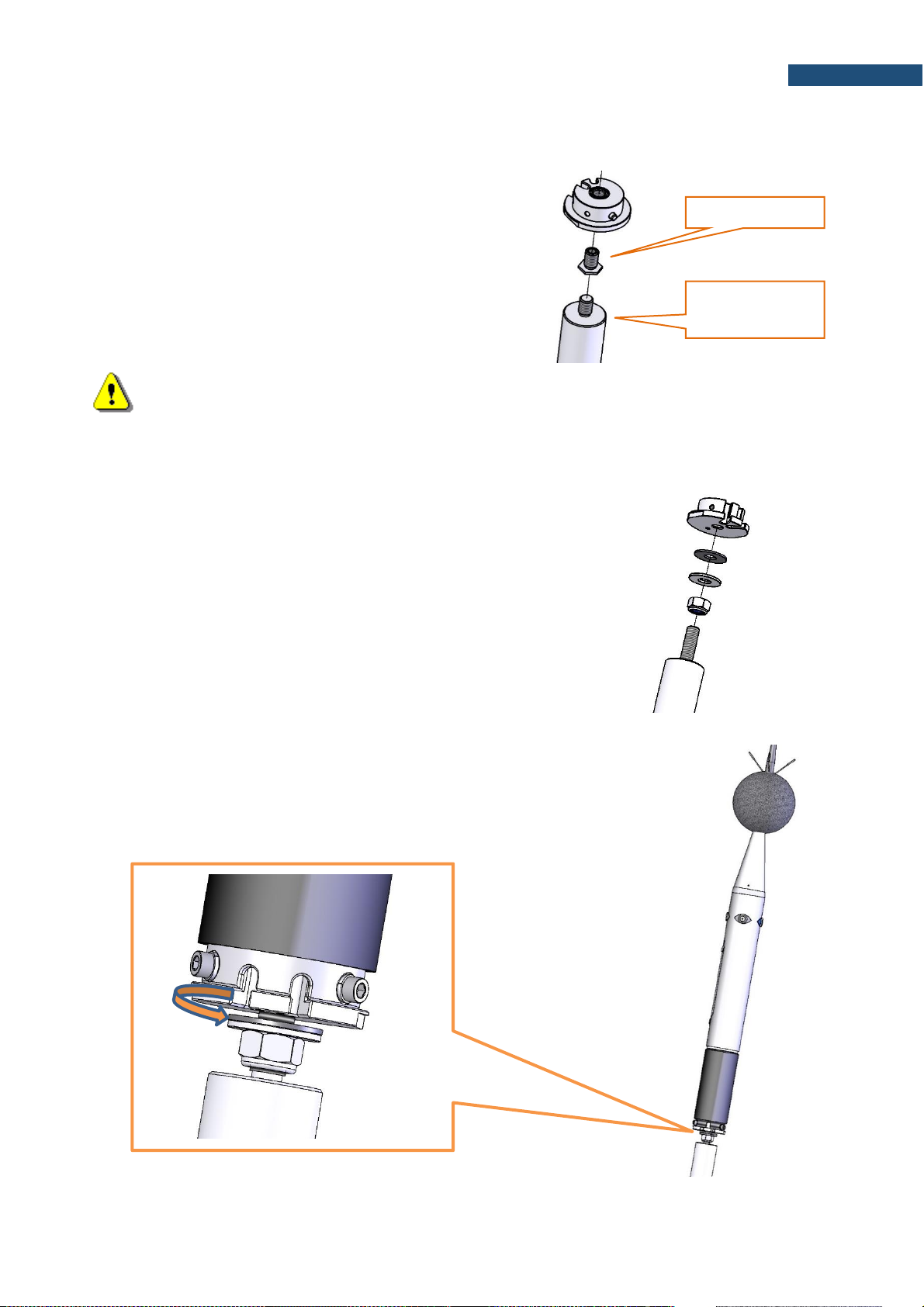
2.3 PRE-ASSEMBLING
Install the microphone and the foam windscreen in the following order:
1. Check that SV 200A is switched off. If the
device is on, turn it off (see Chapter 3.2)
2. Place SV 200A upright (outer cone
facing up) on a stable horizontal flat
surface.
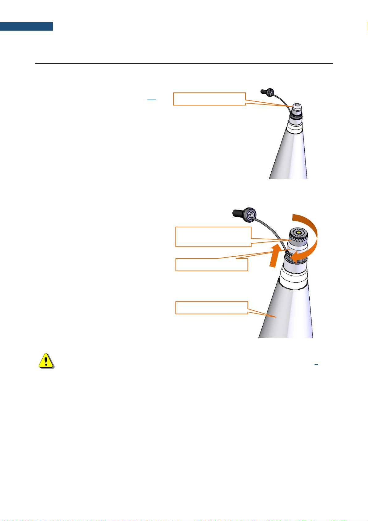
3. Take off the protective cap from the
microphone socket.
4. Holding outer cone in one hand, use the
other hand to screw the microphone on
the matching thread extending from the
outer cone (rotating the microphone
clockwise).
5. The sealing hood should be pulled up to
the top (to contact the microphone).
Note: It is advised to calibrate the SV 200A at this point. For more information see Chapter 0.
hold firmly with one hand
screw the microphone on
the microphone socket
pull sealing hood up
take off protective cup
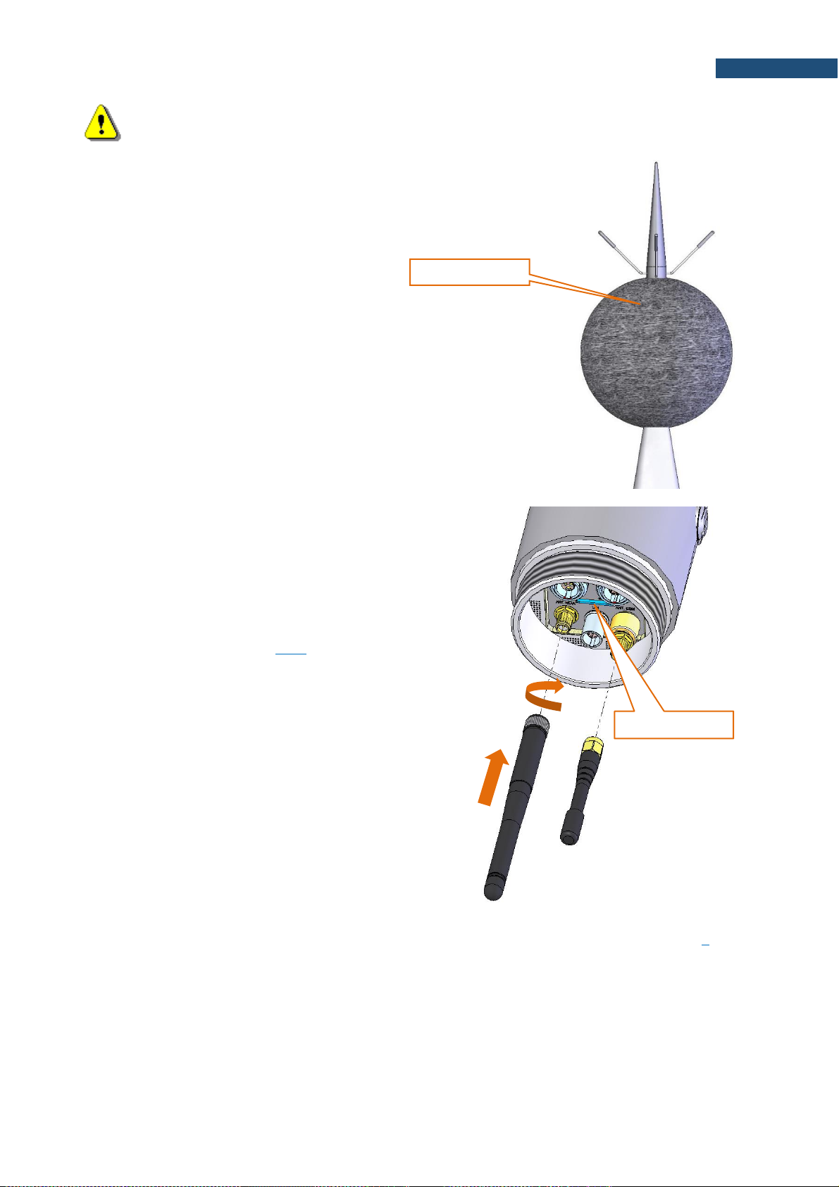
Page 18
18
SV 200A User Manual
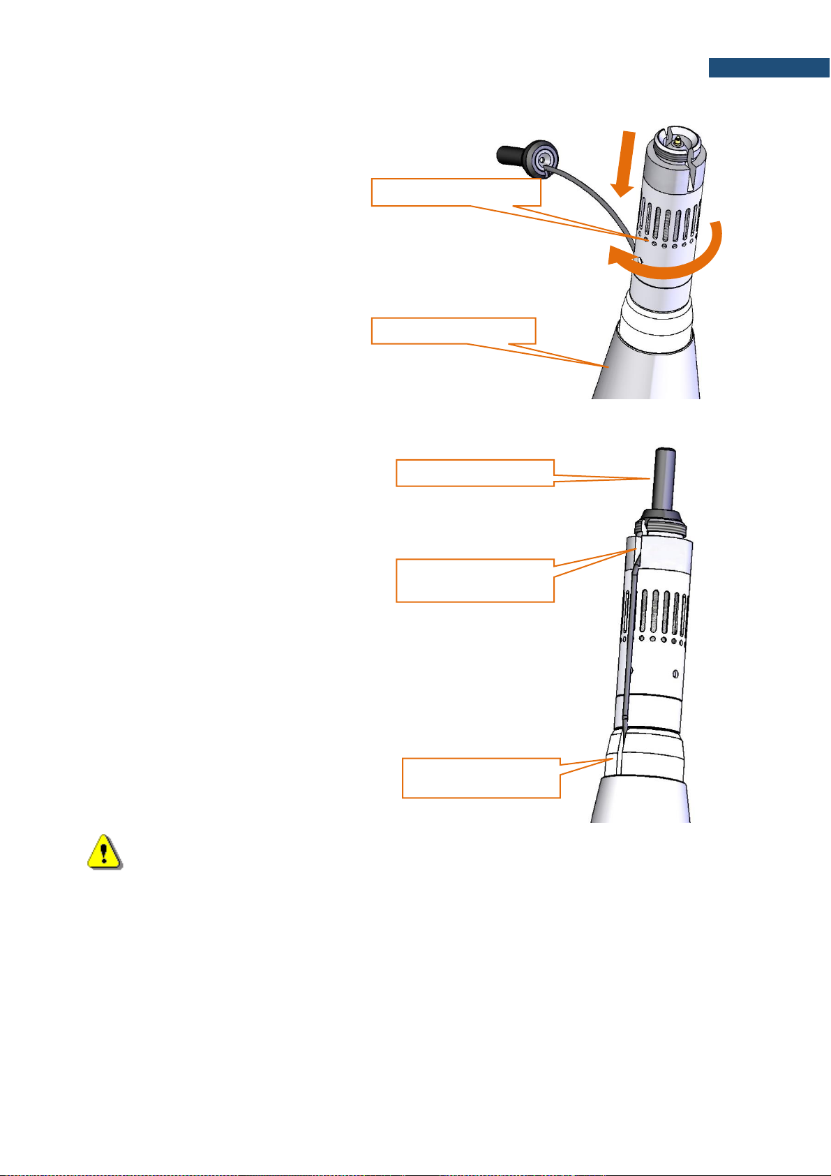
6. Hold the outer cone with one hand,
use the other hand to screw on the
microphone protective sleeve
rotating it clockwise.
7. Align moving ring with the slot of the
microphone protective sleeve so that
the cable is not bent in any direction.
Gently place the actuator located at
the end of the cable in the dedicated
socket. Put the actuator's cable into
the slot of the sleeve.
If the actuator's cable is too long,
decrease the length pushing its
lower end inside the casing.
Note: It is important to keep the microphone protective sleeve still, to protect actuator’s cable from
damage.
hold firmly with one hand
screw the sleeve on
insert into the socket
place the actuator cable
in the slot of the sleeve
align with the slot of the
Page 19
19
SV 200A User Manual
8. Hold the microphone protective
sleeve and the top cone with one
hand, use the other hand to screw on
the extension sleeve, rotating it
clockwise.
Tighten it to the stop, but "carefully"
- too strong tightening can cause
loosening of the left screw inside.
9. Slide the foam windscreen onto the
extension sleeve and push the foam
until you see the lateral hole.
10. Insert the 3 mm Allen key into the
hole.
11. Holding the Allen key and the
extension sleeve in one hand to keep
them still, use the other hand to
screw on the top cone with the antibird spikes, rotating it clockwise.
Tighten it to the stop, but "carefully"
- too strong tightening can cause
loosening of the left screw inside.
hold firmly with
one hand
screw the
extension sleeve
push the foam windscreen
until you see the lateral hole
hold the Allen key
firmly in one hand
screw the top cone
2
Page 20
20
SV 200A User Manual
Note: It is important to keep the extension sleeve still, to protect actuator cable from damage.
12. Take the Allen key out from the
extension sleeve.
13. Move the foam windscreen to the
place right under the spikes of the
anti-bird device, make sure it covers
the microphone protective sleeve.
14. Put the device horizontally to gain an
easy access to the socket panel.
15. Make sure that the instrument is
switched off!
16. Insert the SIM card into the SIM card
slot (according to Chapter 3.1.1).
17. Connect wireless antennas.
The device prepared this way is ready for the configuration of the remote connection (see Chapter 7).
cover the hole
insert SIM card
Page 21
21
SV 200A User Manual
2.4 MOUNTING
The mounting described in this manual is based on the mast type systems, that are recommended by
Svantek.
Note: If other types of mounting than mounting on the mast is going to be applied, consult Svantek,
since only recommended type of mounting assures declared acoustical characteristics of the
station.
Coaxial mounting of the device on the mast Φ45 mm ended with a bolt M14 is recommended.
Note: The M14/
3/8
” adapter is intended for mounting SV 200A on photographic and light tripods. It
should not be used for unattended environmental monitoring.
Note: Make sure SB 274 power supply unit is not connected to mains before full system installation.
Note: Before installing the station at the
measurement site, make sure that the protective
caps on the four anti-bird spikes are removed.
It is recommended to use the protective caps
during transportation.
2.4.1 Mounting SV 200A on the mast
1. Unscrew two bolts attaching the
mounting sleeve to its bottom with
the 5mm Allen key.
2. Push the pin in the third hole in the
bottom using a longer arm of the
Allen key and take the bottom off the
sleeve.
3. If the mast has M14 thread unscrew
the M14/
3/8
” adapter from the bottom
of the mounting sleeve base using
the special 22 and 65 mm spanners.
pin
bolt
M14/
3/8
”
adapter
Page 22

22
SV 200A User Manual
4. Remove the base out of the sleeve.
5. Remove the seal from the cylinder
pulling it by the grip.
6. Screw the base of the mounting
sleeve on the M14 thread of the
mast (if you use aligning to the North
set see Chapter 2.4.3).
7. If you don’t use aligning to the North
set tighten the bottom of the
mounting sleeve up with the special
open spanner 65 mm.
8. Make sure SV 200A is switched off.
9. Plug the power supply cable
connector in to the DC IN socket on
the connector panel.
10. Optionally, plug the lemo connector
of the USB, weather station or alarm
lamp cable into the MULTI I/O
socket on the connector panel.
11. Connect antenna(s).
base of the
mounting sleeve
tip of the mast
DC IN
socket
MULTI I/O
socket
Page 23
23
SV 200A User Manual
12. Pass the cables through the
mounting sleeve and screw the
mounting sleeve on the thread of
SV 200A.
13. Insert the cables into the holes of the
seal through the cuts in the seal
edge.
14. Insert the seal inside the mounting
sleeve until it stops, pushing it by the
plastic grip.
15. Holding the seal pull the cables out
to the stop.
The silicon seal is designed to protect
the instrument from atmospheric
humidity and what is more important to
dump acoustic resonances.
The seal is designed so that 5 positions
are foreseen for 5 combinations that
can be created from 3 cables.
Each hole has a cut in the seal that
enables simple insertion of the cable
into the hole.
16. Push the pin in the base of the
sleeve with 5 mm Allen key.
17. Put the mounting sleeve on the base
holding the cables in the slots of the
sleeve.
18. When the pin is in the third hole of
the sleeve, lay the cables in the slots
of the base.
19. Screw both bolts fastening the
sleeve to the base using the 5 mm
Allen key.
Note: During laying the cables in the slots, the seal will be positioned so that not used holes will be
closed by the base providing reliable tightness and sound insulation of the instrument.
two thick cables
one thick and one
thin cables
no cables
two thick and one
thin cables
one thick cable
Page 24
24
SV 200A User Manual
2.4.2 Mounting on 3/8” thread
To mount SV 200A on the 3/8” thread use
the M14/
3/8”
adapter.
Note: Tripod or pole with 3/8” thread is not recommended for permanent installation.
2.4.3 Mounting the SV200A station on the mast aligning to the North
Mast requirement: the length of the threaded bolt should be at
least 45 mm.
Additional elements: steel washer, rubber washer, prevailing
torque hex nut (with plastic insert).
Mounting method:
1. Screw the prevailing torque hex nut (plastic down),
apply a steel washer and a rubber washer.
2. Screw the base of the sleeve to the stop (resistance
will be on the screw of the sealer inside the base)
and unscrew it again by approx. 1 turn.
3. Mount the entire station on the base.
4. Position the station towards the North.
5. Tighten the prevailing torque hex nut to the stop (up
to the base), blocking the rotation of the station (with
the key placed on the base).
M14/
3/8
” adapter
tip of the mast
with 3/8” thread
Page 25
25
SV 200A User Manual
2.5 ANTI-THEFT PROTECTION
There is a special swivel eye in the kit that can be used as antitheft protection of your SV 200A with the use of locking cable.
It is necessary to screw it to the base of the sleeve with the
special key.
2.6 WINDSCREEN PROTECTION
The SA 209 foam reduces the effect of wind on measurement results.
Note: The windscreen influences the free-field characteristics of the instrument, therefore it is
important to check its condition regularly. In the case of visible degradation of the foam surface it
must be replaced by the new one.
During continuous usage, the SA 209 foam is exposed to different weather conditions with possibility of
causing mechanical damage to the foam’s structure. Therefore, it is recommended, at least once a quarter
(3 months), to check the condition of the foam by examining the surface for cracks by squeezing the foam.
If cracks or holes are observed, the SA 209 foam must be replaced.
The SA 209 foam must be replaced whenever squeezing it causes severing of small pieces of its surface.
Replacement of the foam windscreen should be performed according to steps 1 to 5 of Chapter 4.1 and
steps 8 to 12 of Chapter 2.3.
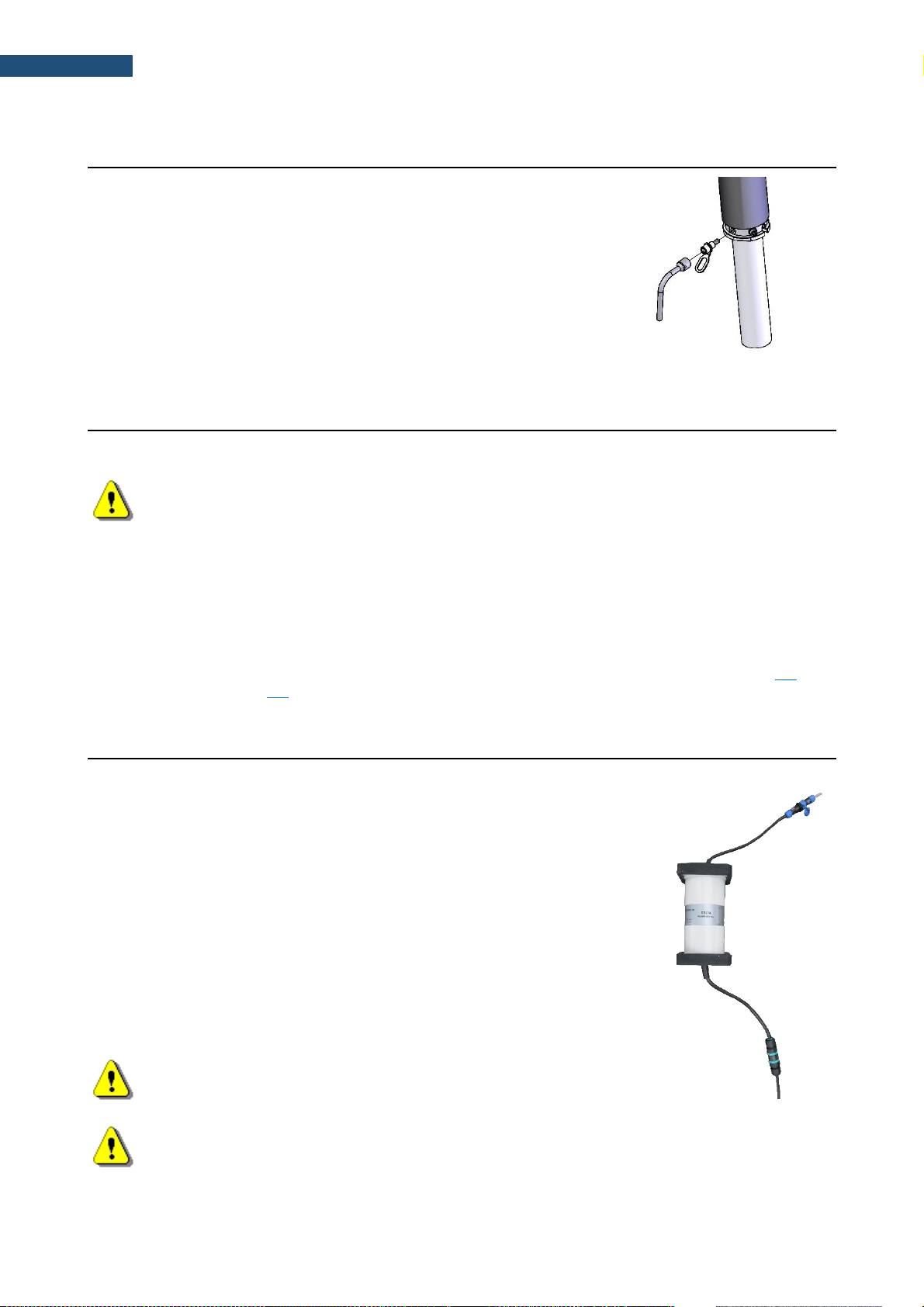
2.7 POWER SUPPLY UNIT
SB 274 is a waterproof single output switching power supply
which is characterised by:
• Universal AC input / Full range (100 ~ 240 V AC)
• Rated power 40 W
• Built-in active PFC function
• Class 2 power unit
• Protections: Short circuit / Over load / Over voltage / Over
temperature
• Fully encapsulated with IP67 waterproof level
• Lemo 1B.303 connector
It is recommended to install the SB 274 power supply unit on a
mast, using 2 steel clamps and in the place not exposed to direct
sun light.
Note: See also SB 274 User Manual.
Note: Even though the power supply has a high IP index (Ingress Protection), it is still not
recommended to leave it on the ground for safety reasons. Good practice is to mount it on the
pole or mast.
Page 26
26
SV 200A User Manual
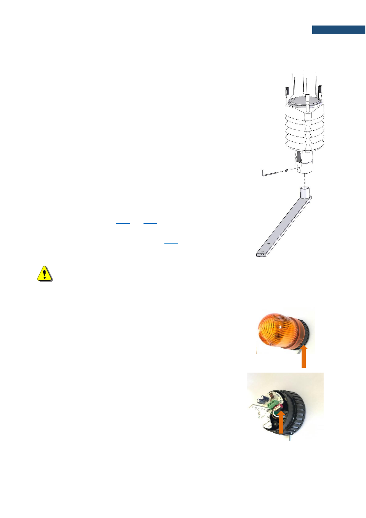
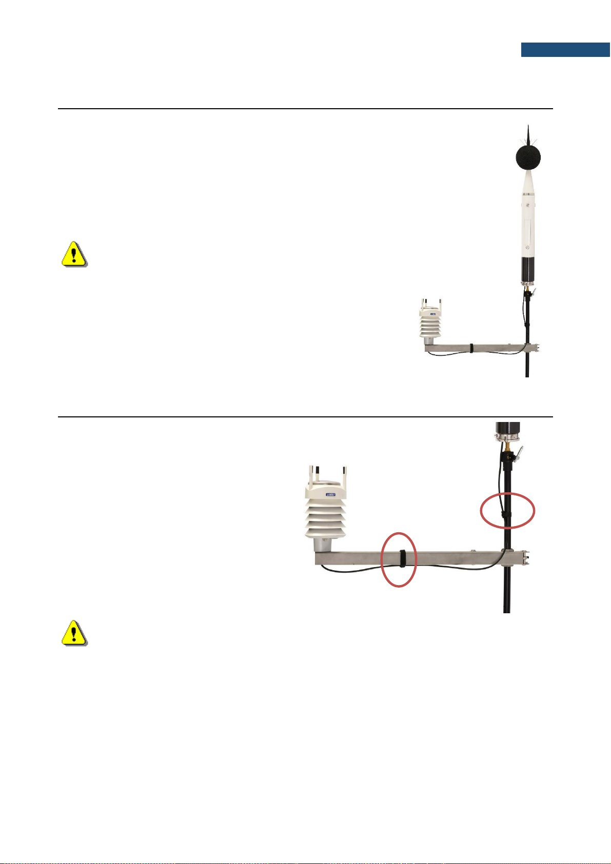
2.8 ASSEMBLING THE SP 275 WEATHER STATION ON THE MAST (OPTIONALLY)
SP 275 is mounted on a meteorological beam that can be
installed on the mast below SV 200A. The distance from the
beam to the SV 200A device should be as great as possible, but
it is limited to the length of the SC 209 cable.
Note: If your Vaisala Weather Transmitter is equipped
with the wind sensor, then it is critical to set the correct sensor
orientation. The North direction is marked at the bottom of the
weather transmitter. Use real-life compass or mobile app to
determine North direction.
2.9 FINISHING
Attach cables to the mast and the
optional meteorological beam. Use
some band clips at intervals not greater
than 50 cm (20”) on the mast and the
cable holders delivered with the kit
(Velcro fasteners) on the
meteorological beam. Lay the cables
so that they are loose at the ends. The
loose cable should hang a bit lower
than the connector to avoid
accumulation of rainwater.
Note: Fixation of cables is important because loosen cables may generate additional noise. As
an alternative way, wrap the cables around the mast.
In the end of installation connect the SB 274 power supply unit and switch on the station.
Page 27
27
SV 200A User Manual
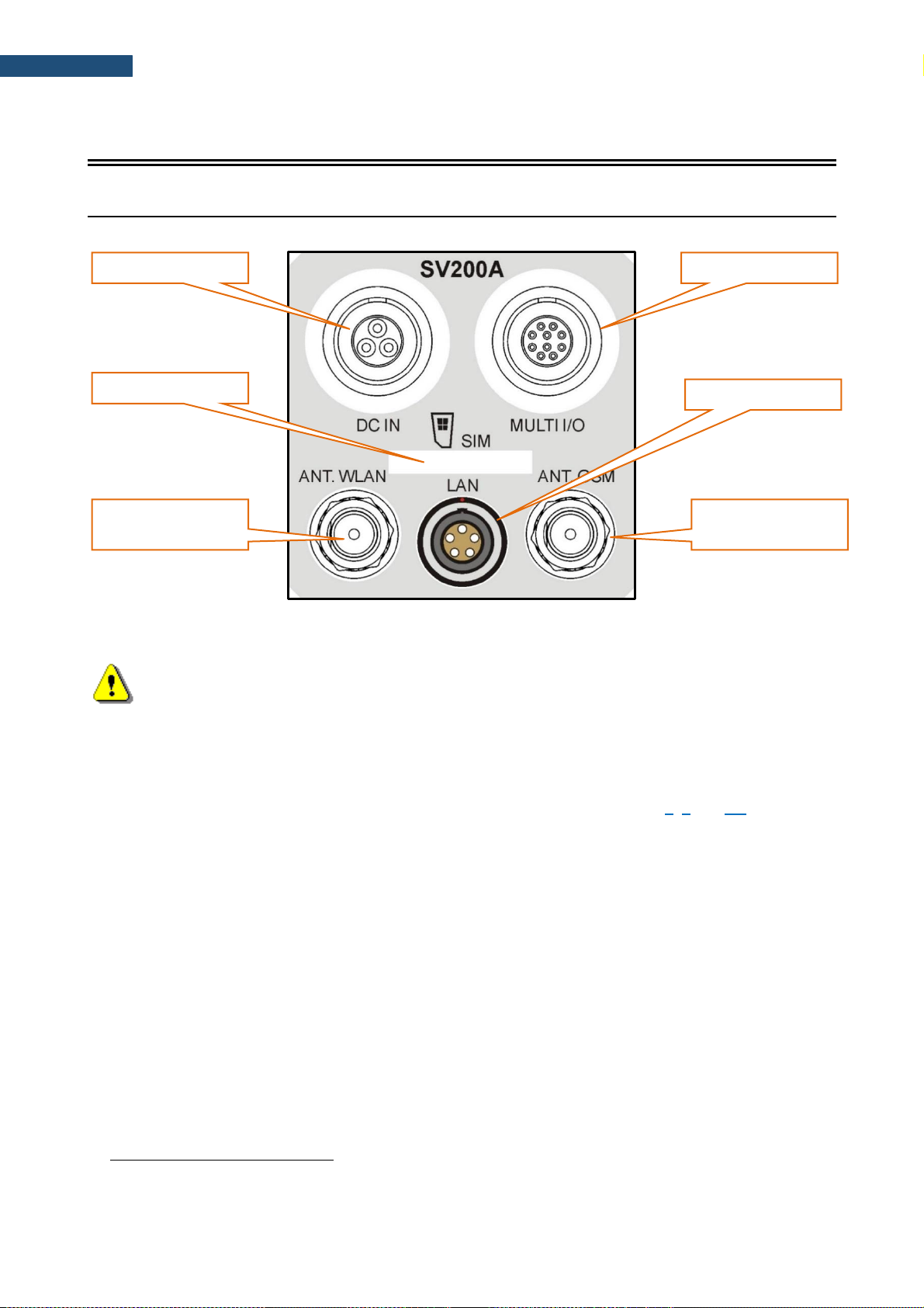
3 SV 200A CONNECTORS AND CONTROL PANELS
3.1 CONNECTORS PANEL
3.1.1 SIM card slot
Note: The SV 200A uses mini SIM card size (25mm x 15mm).
The SIM card should be inserted into the slot according to the drawing on the panel. Push the card in until
you feel a click.
To remove the SIM card from the slot push it until you feel the click and pull the card out. Use tweezers to
remove the SIM-card from the slot.
Further information on configuration of the 3G connection can be found in Chapter 6, 7 and 9.3.
3.1.2 DC IN socket
The DC IN socket is used to connect an external power source, i.e. included power supply, optional solar
panel or external 12-24 V battery.
SV 200A can be powered using one of the following power sources:
• Li-Ion batteries, fitted internally. Operation time with the internal Li-Ion batteries depends on the
power consumption:
➢ up to 7 days – both modems are off,
➢ up to 4 days2 – only 3G modem is on,
➢ up to 2.8 days2 – only WLAN module is on,
➢ up to 3 days2 – only LAN module is on.
• Included AC power supply unit SB 274. Input 90-305 VAC, output +15 VDC 2.7A, IP67 housing.
• Optional solar panel. MPPV voltage 15-20 V, connected directly to SV 200A, without using power
conditioner.
• External DC source. Voltage range 10.5 V – 24 V, e.g. 12 V or 24 V battery.
2
One-minute data transmission with one hour cycle
WLAN Antenna
socket
GSM Antenna
socket
SIM card slot
LAN socket
DC IN socket
Multi I/O socket
Page 28
28
SV 200A User Manual
The internal battery is charged in a fully automatic cycle, when the instrument is connected to any external
power source. SV 200A charges itself regardless of whether it is turned on or off. The weather conditions
(i.e. temperature) are taken into account while charging to prevent any damage of the battery caused by
charging in too high or too low temperature.
Note: SV 200A is equipped with the mechanism which protects the internal Li-Ion batteries
from damage caused by critical discharge. When the battery is running flat, the instrument is
automatically switched off.
Note: SV 200A should not be stored for a long time with discharged Li-Ion batteries. Storing
batteries in discharged condition may damage them. If so, warranty for Li-Ion battery is void.
Note: If SV 200A is planned to be stored for a long period of time, it is recommended to charge
its batteries up to 60% of their capacity. Batteries should be charged at least once per 6 months.
3.1.3 External Communication Interface socket
The MULT. I/O socket enables the user to connect the instrument to one of the following devices:
• PC (via USB)
• SP 275 weather station (via RS232)
• alarm lamp (passive, 12V 1A max)
• external trigger (digital input/output signal)
Note: While connecting your SV 200A to a PC by the SC 256A cable, first insert the lemo plug
into the instrument’s MULT. I/O socket and then the USB plug into the PC!
3.1.4 LAN socket
LAN socket is used for connection SV 200A to the local area network using SP 200 adapter.
3.1.5 Antenna sockets
There are two antenna sockets: for 3G and WLAN communication.
After plugging the antenna into the socket, the screw should be tightened to light resistance only. Do not
over tighten this connector.
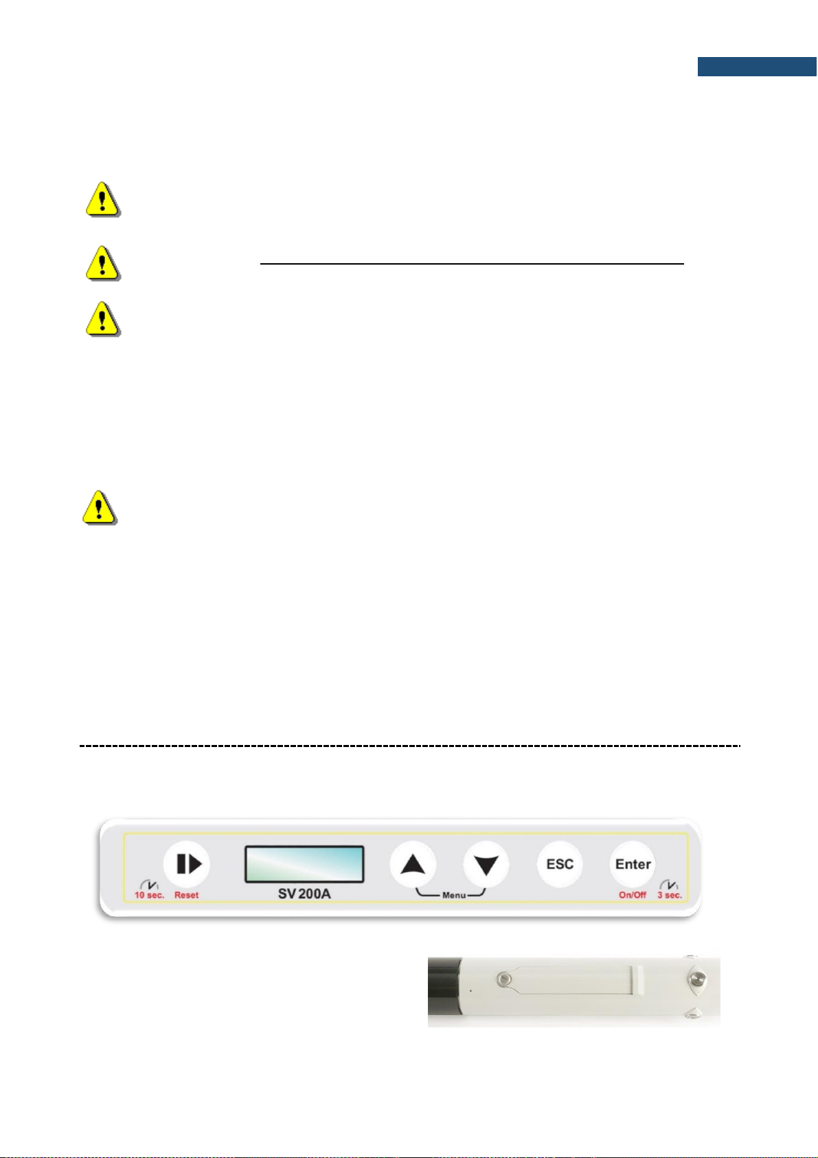
3.2 CONTROL PANEL
SV 200A is dedicated for the outdoor monitoring and remote control via mobile 3G network, LAN or WLAN.
However, it can be also controlled from the control panel with the use of five keys and a display (128 x 32
pixel resolution).
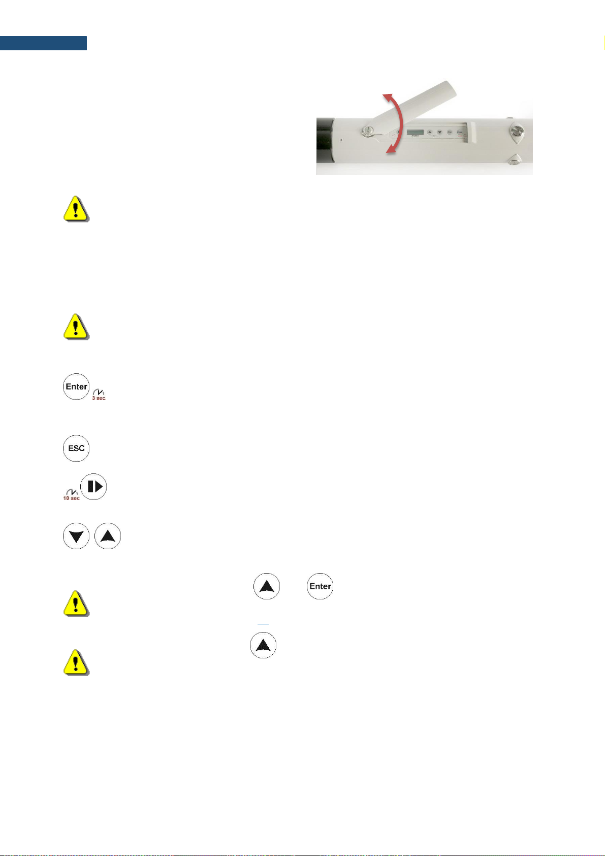
During outdoor operation, the control panel should
be closed by the flap. Closed flap assures protection
of the instrument’s user interface from environmental
impact and, what is more important, assures that
acoustical direction characteristics are within
declared tolerances.
Page 29
29
SV 200A User Manual
To uncover the control panel, unscrew the coinoperated screw (with your fingers, or the first turn
with the coin and then the fingers) slightly to the stop.
If the instrument is in vertical position the flap should
slide down and its upper (rectangular) part should
slide out from under the eaves. If the flap does not
slide down, slightly press the lower part with your
finger and move it down. Then turn the flap clockwise
(or counter-clockwise).
Note: The coin-operated screw should be loosened using, for example, a coin and then
unscrewed with fingers until it stops. Opening the flap with the screw left in the intermediate
position may damage the varnish of the casing.
To close the control panel, turn the flap so that its upper, rectangular part jumps into the notch of the casing.
If the lower part of the flap is pressed against the head of the screw through the inner spring, it should be
lightly pressed (so as not to damage the lacquer on the flap). Move the flap up (with your finger) by pressing
it all the time so that the upper part of the flap is hidden under the notch. Tighten the screw to the stop
(finger, possibly the last rotation by the coin) by pressing the flap all the time.
Note: Operate carefully so that the metal edges of the flap do not damage the varnish on the
surface of the casing, especially at the edge of the notch.
Five control keys enable following functions:
• turning On/Off the instrument when holding 3 sec,
• opening a position in the menu list,
• entering editing mode for the parameter,
• confirming made changes,
• changing main results/status views,
• returning to the upper menu list,
• exiting the current parameter edition without saving changes,
• changing measurement/status views,
• starting or stopping measurements,
• resetting the instrument when holding 10 sec,
• starting the calibration,
• staring the system check,
,
• selecting position in the menu or parameter list,
• changing the parameter value,
• opening the Menu by pressing both keys simultaneously,
• changing profiles/results in the measurement view.
Note: Pressing and holding and keys simultaneously during the instruments
switching on longer than 3 seconds, starts the BOOTSTRAP mode of SV 200A, used for
firmware update (see Chapter 10).
Note: Pressing and holding during the firmware booting when Svantek icon appears,
enables loading factory settings before the instrument’s start. This Factory Settings function
will reset all settings including communication one.
Page 30
30
SV 200A User Manual
4 CALIBRATION
The instrument is factory calibrated with the supplied microphone for the reference environmental conditions
(see Appendix C). The microphone sensitivity is a function of the temperature, ambient pressure and
humidity, and when the absolute sound pressure level value is required, the absolute calibration of the
measurement channel should be performed.
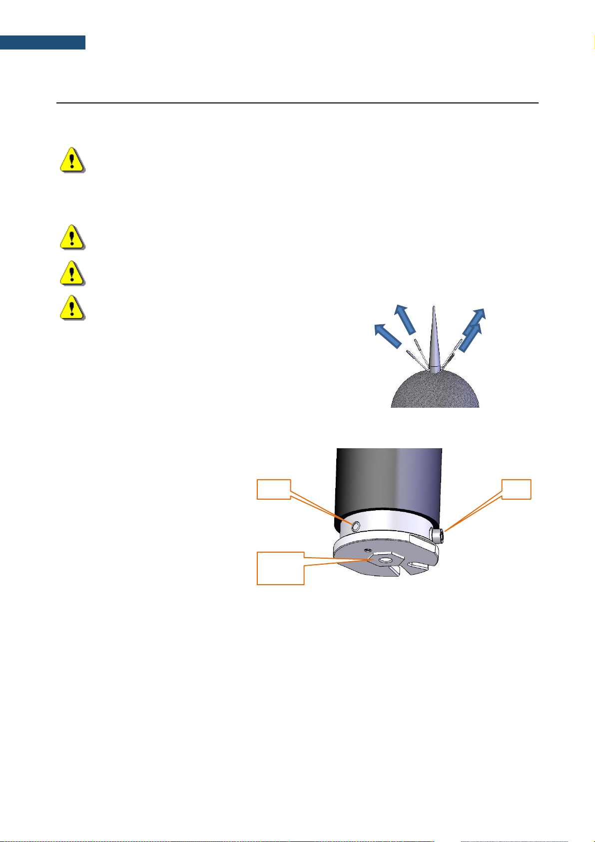
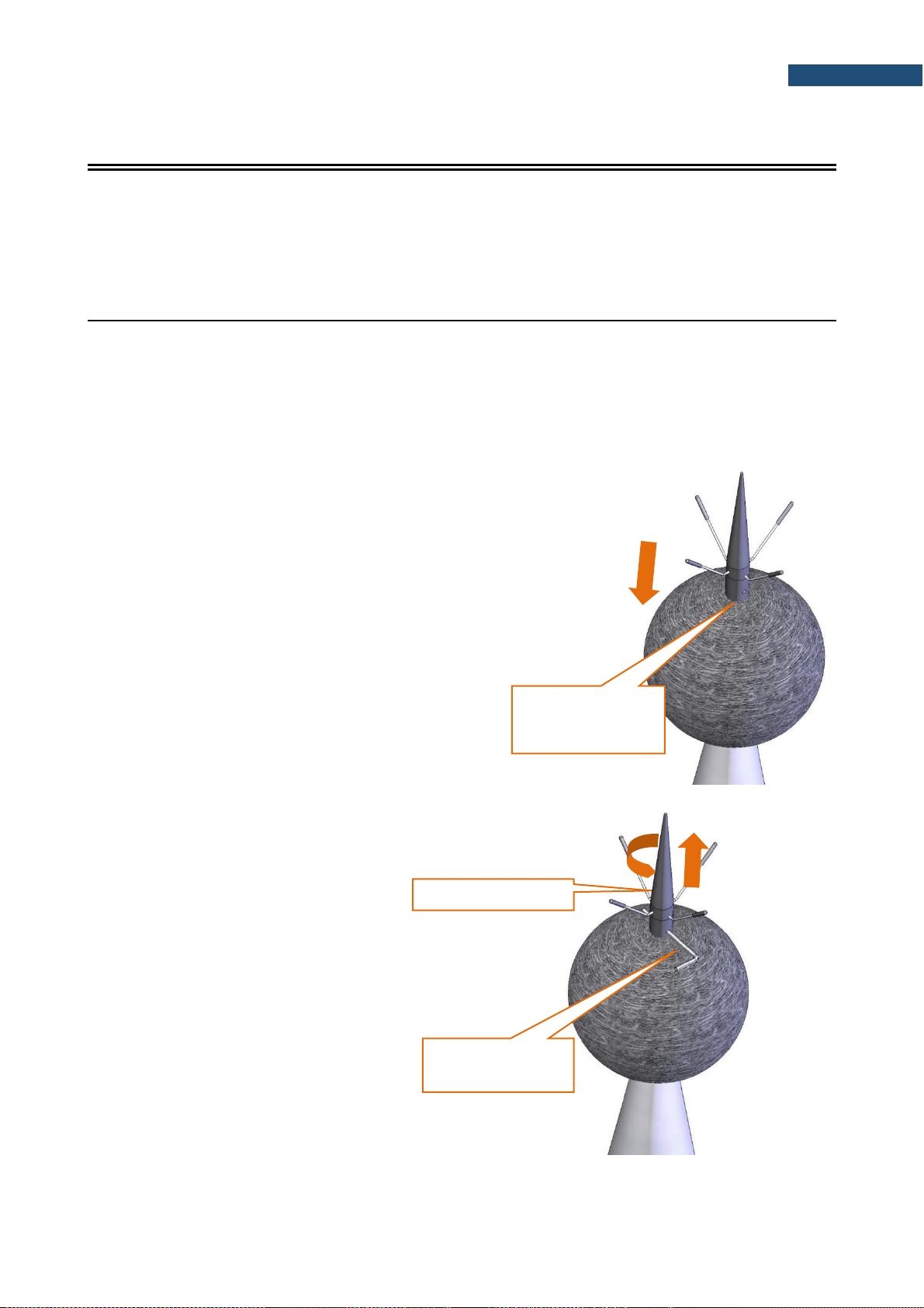
4.1 PREPARATION FOR CALIBRATION
If the SV 200A instrument is assembled and needs calibration, it is necessary to disassemble following parts
of SV 200A:
• con nozzle,
• SA 209 foam windscreen,
• extension sleeve,
• microphone protective sleeve.
To access the microphone, do what
follows:
1. Push the foam windscreen until you
see the lateral hole.
2. Insert the 3 mm Allen key into the
hole.
3. Holding the Allen key and the
extension sleeve in one hand to keep
them still, use the other hand to
unscrew the top cone with the antibird spikes, rotating it counterclockwise.
push the foam
windscreen until you
see the lateral hole
hold the Allen key
firmly in one hand
unscrew the top cone
2
Page 31

31
SV 200A User Manual
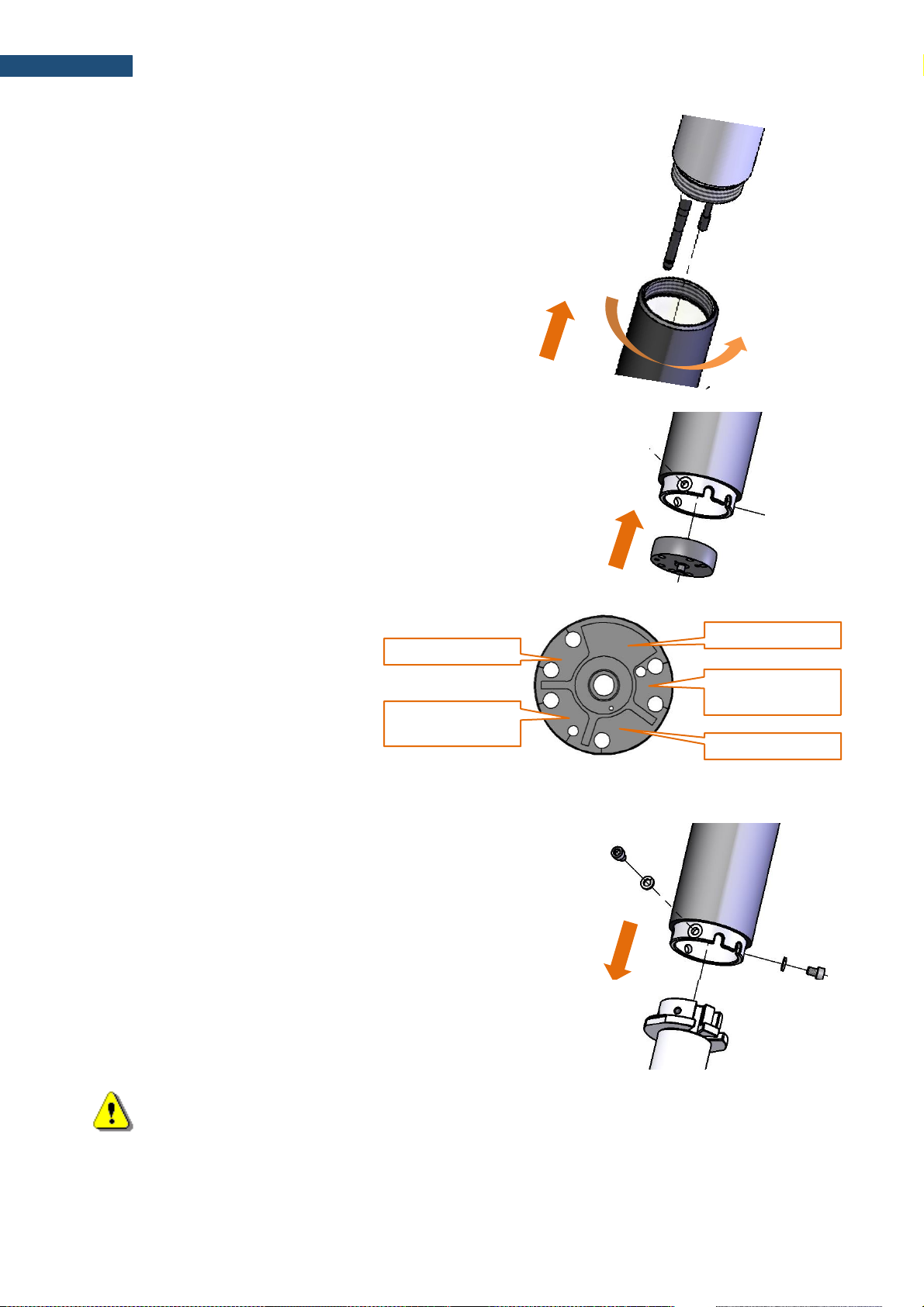
Note: It is important to keep the extension sleeve still, to protect actuator cable from damage.
4. Take the Allen key out from the extension
sleeve.
5. Take the foam windscreen off the
extension sleeve.
6. Hold the microphone protective sleeve and
the outer cone with one hand, use the other
hand to unscrew the extension sleeve,
rotating it counter-clockwise.
Note: It is important to keep the microphone protective sleeve still, to protect actuator cable from
damage.
take the foam windscreen off
hold the microphone
protective sleeve
firmly with one hand
unscrew the
extension sleeve
1
2
Page 32

32
SV 200A User Manual
7. Gently remove the actuator form the
socket. Let the cable hang loose.
8. Take the outer cone with one hand, use
the other hand to unscrew the
microphone protective sleeve rotating it
counter-clockwise.
9. Attach the sound calibrator (SV 36 or
equivalent 114 dB/1000 Hz) carefully
on the microphone.
10. Switch on the calibrator and wait for the
tone to stabilize (according to the
calibrator specification) before starting
the calibration measurement.
11. Perform the calibration measurement –
see Chapter 4.2 and 4.3.
12. Take the calibrator off after the
calibration.
13. Assemble SV 200A according to
Chapter 2.3.
remove from the socket
let the cable hang loose
hold firmly with one hand
unscrew the sleeve
1
2
calibrator
Page 33
33
SV 200A User Manual
Note: During the calibration measurement, the level of external disturbances (acoustic noise or
vibrations) should not exceed a value of 20 dB below the level of signal generated by the
calibrator (94 dB when using a calibrator that generates 114 dB).
Note: It is also possible to use an electro-mechanical pistonphone, which generates the signal
(ca 124 dB) or different type of sound calibrator dedicated for ½” microphones. In any case,
before starting the calibration measurement, you should set in the instrument the level of the
signal, which is stated in the certificate of the calibrator.
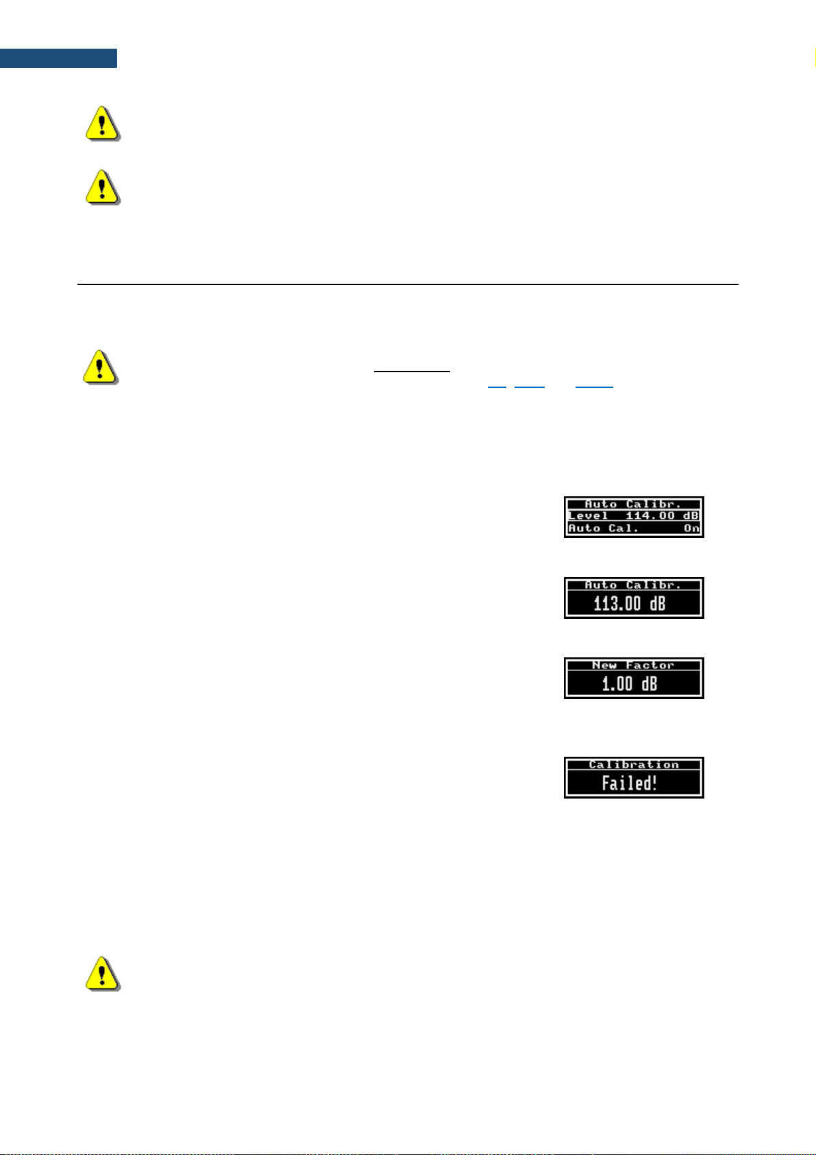
4.2 AUTOMATIC CALIBRATION
Automatic calibration feature was implemented to make calibration as easy as possible and to allow technical
personnel to perform a calibration of SV 200A with minimum knowledge and with minimum steps. Automatic
calibration doesn’t require usage of any interface with SV 200A.
Note: Automatic Calibration feature is switched off by default. You can switch this feature on from
the control panel or via applicable software (see Chapter 5.1, 8.4.1 and 9.8.11)
When the automatic calibration is switched on, the instrument periodically compares the measured Leq(C)
level averaged by 1 second with the calibration level set up by the user. To perform the automatic calibration,
follow next steps:
1. Attach the calibrator to the microphone and switch it on (if the used calibrator doesn’t have switch-on
automatic feature).
2. Switching the calibrator on begins the Automatic Calibration
process if the difference between the calibration Level value set
up in the Auto Calibration screen and the signal level generated
by the calibrator is ±5dB.
3. During the calibration measurement, the level of the calibration
signal will be displayed. If three consecutive 1-second results are
stable within ±0.1dB margin, the calibration measurement is
stopped, and the calibration factor is calculated.
4. If new calibration factor is in the range ±3dB, Automatic
Calibration will be successful, and new calibration factor will be
saved and displayed. From that moment, new calibration factor
will be the current calibration factor without confirmation from the
user.
5. If the calculated calibration factor is out of the range ±3dB,
Automatic Calibration will fail and the message “Failed!” will
appear on the display. In such case the new calibration factor will
not be saved and the calibration factor just before the calibration
will still be valid.
6. Detach the calibrator from the microphone. After detaching the calibrator from the microphone SV 200A
returns to its previous state.
During the automatic calibration, main measurements are stopped (if were running) and the outdoor filter is
turned off. After removing the calibrator from the microphone, main measurements will restart after 1 minute
(auto-start security mechanism) with switched on outdoor filter.
Note: Running main measurements are always stopped during automatic calibration
procedure.
Page 34

34
SV 200A User Manual
4.3 CALIBRATION WITH THE USE OF THE CONTROL PANEL
The calibration via the control panel (manual calibration) gives the user an option to decide whether the new
calibration factor should replace the current one.
Note: Before proceeding with the manual calibration you should be sure that the Automatic
calibration is Off (see Chapter 4.2).
To perform the manual calibration, follow next steps:
1. Uncover the control panel of SV 200A by unlocking
and shifting the control panel flap.
2. Press the and keys simultaneously to open the Menu
window of the panel display.
3. Press the key to open the Function position, select the
Calibration position with the key and press the key to
open it.
4. Press the key to open the By Measurement position and set
up the required calibration Level according to the calibration card of
your calibrator. Press the key to confirm the new calibration
level.
5. Attach the calibrator on the microphone and switch it on (if the used
calibrator doesn’t have switch-on automatic feature).
6. Start the calibration measurement by pressing the key. During
the calibration measurement, the level of the calibration signal will
be displayed. If three consecutive 1-second results are stable within
±0.1dB margin, the calibration measurement is stopped, and the
calibration factor is calculated. Otherwise the instrument will stop the
measurement and display the message “Failed!” after 10 seconds
from the calibration measurement start.
7. The successful calibration will result in calculation of the new
calibration Factor, which should be confirmed (Yes) with the
key or rejected (No) with the key. After confirmation, the
calculated calibration factor will be the current calibration factor.
8. If the calculated calibration factor is out of the range ±20dB, the
calibration will fail and the message “Failed!” will appear on the
display.
9. Detach the calibrator from the microphone.
Page 35

35
SV 200A User Manual
4.4 CALIBRATION WITH THE USE OF SVANPC++ AND USB CONNECTION
1 Connect SV 200A with the PC using SC 256A cable and start SvanPC++.
2 When SV 200A instrument wizard appears on the screen, click Calibration.
3 Set desired calibration level in the SV 200A Calibration window.
4 Attach the calibrator on the microphone, switch it on (if the used calibrator doesn’t have switch-on
automatic feature) and start the calibration measurement by pressing the Start button. The
successful calibration will result in calculation of the Calibration Factor. Calibration measurement
can be terminated by pressing the Terminate button.
Start button
Calibration level
Calibration button
Page 36

36
SV 200A User Manual
5 Confirm obtained calibration factor by clicking Yes. New calibration factor will replace the previous
one in the instrument’s memory and will be applied to all subsequent measurement results.
4.5 SYSTEM CHECK WITH THE USE OF ELECTROSTATIC ACTUATOR
The electrostatic actuator is used for remote system check of the instrument, which enables checking
the acoustical measurement input of the instrument.
The System Check procedure consists of a sequence of measurements of background noise and a level
generated by the electrostatic actuator (94dB). The measurement of background noise is carried out
before and after the measurement of a signal level from the actuator. It is assumed that a one-second
RMS(C) of the background noise measured for 3 consecutive seconds must be at least 20 dB lower
than the nominal level generated by the electrostatic actuator (94dB). If this condition is not met, system
check is unsuccessful. If the background condition is met, the station switches on the actuator and waits
for stable one-second RMS(C) values with an accuracy of ±0.1dB. The stabilized RMS(C) value of the
signal from the actuator cannot deviate from the nominal value (94dB) more than ±1dB. The system
check result (OK or Failed) together with the measured levels the background noise and the signal from
the actuator is recorded in the calibration and system check history file. The duration of the system
check sequence is typically <15s and can be extended up to <25s in the case of longer stabilization
period of the RMS(C) generated by the actuator. In the case of the automatic system check function,
when the test result is negative, it is repeated 4 times more every 1 minute to obtain a positive test
result. If the result is still negative, subsequent attempts are abandoned to the next planned system
check.
The measurements are paused for the duration of the system check procedure (active pause).
Terminate button
Calibration factor
Page 37

37
SV 200A User Manual
Note: Unlike Calibration procedure, system check does not change the calibration factor of the
instrument.
The electrostatic actuator generates 1 kHz tone equivalent to sound pressure level of 94 dB (re. 20 μPa).
It can be turned on or off and programmed remotely by the user:
- via SvanNET Web service, in the Status tool (see Chapter 8.3) or
- via SVAN PC++ Remote Control software, in the Live Results window (see Chapter 9.6).
Auto System Check feature of SV 200A enables configuring and scheduling automatic check of the
instrument:
- via SvanNET Web service, in the Automatic system check panel (see Chapter 8.4.1) or
- via SvanPC++ Remote Control software, in the Automatic system check panel (see
Chapter 9.8.11).
Page 38

38
SV 200A User Manual
5 OPTIONS OF THE STATION CONTROL
Prior to start operating SV 200A it is necessary to assemble the instrument according to the instructions in
Chapter 2, connect the power source if required and switch the instrument on by pressing the key and
holding it min 3 sec.
Basic control operations include:
• Measurements start/stop
• Measurement results viewing
• System checking/calibration
• Files downloading/uploading
• Instrument/measurement configuration
• Firmware upgrading.
Most of these operations can be performed manually using the instrument’s Control panel.
However, SV 200A is dedicated for the outdoor monitoring and must be controlled remotely via mobile
network with the use of internal 3G modem, via LAN or WLAN with the use of the internal WLAN module.
SVANTEK offers two tools which enable remote functionality: SvanPC++_RC software and SvanNET web-
service.
SvanPC++_RC is a standard Svantek SvanPC++ software for Windows augmented by Remote
Communication module (RC). This software is dedicated to all types of communication channels of mobile
network as well as for WLAN. SvanPC++ enables advanced data processing and reporting.
SvanNET is a user-friendly web-service enabling most of basic operations. This software doesn’t require
installation on a PC and can be used on any PC and mobile device via standard Internet browser.
5.1 SV 200A MANUAL CONTROL VIA CONTROL PANEL
When SV 200A is turned on, the measurement Start and Stop is done with
key. The running measurement is signalled by live dots underlining of
the displayed result.
After pressing start key, the measurement delay is counting down and after
this the measurement starts.
5.1.1 Measurement results viewing
The View mode is a way in which the measurement parameters are presented. In other words, when you
change the View mode, specific measurement parameters and status information will be presented in
different manner. The View modes can be changed with the or key.
SV 200A has the following View modes:
▪ Charging view mode,
▪ Running SPL view mode (active only when measurements are stopped),
▪ Basic view mode,
▪ Large view mode,
▪ Vertical view mode,
▪ Powering status view mode,
▪ Communication information view mode.
Page 39
39
SV 200A User Manual
Charging view mode
Charging view became active when the external power supply is connected to switched off SV 200A. Just
after connection of the external power supply the big battery icon with percentage of charging is displayed
and after 10 seconds the floating battery icon appears instead of big battery icon.
If power supply unit is disconnected SV 200A will be switched off after a short period.
If in this mode, USB cable is connected to the PC or the key is pressed SV 200A will start executing
firmware program and finally enter the Running SPL view.
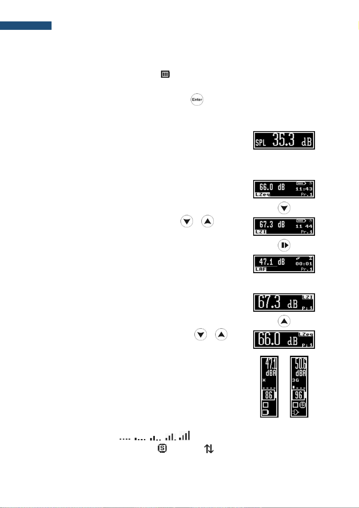
Running SPL view mode
Running SPL view is used when the measurement is not running, e.g. when
the instrument is in standby mode before or after the measurement. In this
mode, the current SPL result is calculated and displayed, but not stored in
the instrument's memory. The purpose of this is to give the user a first
indication of the noise level. In this view mode the instrument behaves as a
simple general-purpose sound level meter.
Basic view mode
The measurement result and its value are displayed in the left part of the
screen. In the right part of the screen, battery icon, real time and profile
number are displayed.
The required measurement result is selected with the or key.
In the right upper corner of the screen, two icons are displayed:
• “battery” icon, showing the status of the internal battery or
• “lighting” icon, showing the status of the external power supply
and
• “clock” icon and real time beneath it or
• “sandglass” icon and elapsed measurement time beneath it.
Large view mode
The measurement result is displayed with big font in the left part of the
screen. In the right part of the screen, the measurement result name and
profile number are displayed.
The required measurement result can be selected with the or key.
Vertical view mode
The measurement result is displayed in a way to enable reading when the
instrument is in the vertical position. Below the result, information about the
instrument status is displayed in the form of icons regarding:
• connection status:
o no active interface { * },
o active interface {2G/3G, WI (WLAN infrastructure mode), WA
(WLAN access point mode) and LN (LAN mode)},
o radio signal power { , , , , },
o connection to the remote peer { (SnanNET), (remote
server, e.g. SvanPC++)},
Page 40

40
SV 200A User Manual
• internal battery capacity { },
• measurement status:
o measurement is stopped { },
o measurement is running {blinking / },
• power source:
o internal battery { },
o solar panel { },
o power supply unit or external DC source { },
o power over Ethernet { },
o USB power { },
• other statuses:
o switched on actuator { },
o active GPS { , blinking when GPS is not fixed }.
Spectrum view mode
1/1 or 1/3 spectra are displayed for LEQ and MAX band results together with
three TOTAL values (TOT A, TOT C and TOT Z). The cursor shows the result
for the band or the result for TOTAL value: central band frequency, result in
dB (for LEQ spectra) and filter (A, C, B, Z) (for MAX spectra). The cursor
position can be changed with the or key.
Power Supply status view presents:
• type of the power Source: internal Battery, power supply unit (Mains),
Solar panel, USB or from the Ethernet (PoE),
• charging Status: Charging or Not Charging,
• estimated working time without charging or time to full charging of the
internal batteries (Time Left),
• the battery Charge status in %,
• battery Capacity in Ah,
• battery temperature in oC (Temp.).
Communication information presents:
• Interface type: 2G/3G, LAN, WLAN, BT (Bluetooth),
• Connection Status: None (if the modem is switched off), Init OK (if
the modem is switched on, but there is no connection), Internet (if the
instrument is connected to the Internet), Connected (if connection
with remote peer, but not SvanNET, has been established), SvanNET
(if the instrument has established connection with the SvanNET webservice),
• Signal level (RSSI) in dBm or None,
• Traffic (amount of sent and received bytes since modem on),
• Modem Manufacturer,
• Modem Model,
• Internal firmware Revision of the modem,
• IMEI number of the modem,
• MAC address of the WLAN module.
Page 41

41
SV 200A User Manual
5.1.2 Configuration Menu
The instrument control panel enables limited tools for configuration the
instrument and measurements. The configuration can be performed through
the instrument’s Menu, which is opened by simultaneous pressing of the
and keys and consists of several configuration sections:
• Function, which enables selecting of the measurement function or
performing calibration;
• Measurement, which enables configuring measurements,
• Display, which enables configuring automatic switching off the
screen;
• Instrument, which enables configuring the instrument’s real-time
clock and viewing instrument’s serial number and firmware version;
• Auxiliary Setup, which enables selecting of the interface language
and recovering factory settings.
The required section can be selected with the or key and opened
with the key. Using the key you can exit the current section.
In the Menu screens, you can:
• select the required position with the or key,
• open new screen of the selected position with the key,
• return to the upper menu with the key,
• make selected parameter ready for changing with the key,
• select parameter value with the or key,
• confirm changes with the key,
• exit the current screen with parameters unchanged with the
key.
For example, to switch auto calibration, you should select the Auto Cal.
position, press the key and select On or Off with the or key.
To confirm the selection, press , and press to exit the
Auto Calibration screen.
Function section contains positions:
• Measurement Function, which enables selecting of the
measurement function: Level Meter, 1/1 Octave or 1/3 Octave.
Page 42

42
SV 200A User Manual
• Calibration, which enables performing calibration By Measurement
using a sound calibrator and switching on/off the Auto Calibration.
• Position System Check, which enables checking the measurement
path using the built-in electrostatic actuator. The System Check
screen shows the result of the previous system check:
o calculated Factor,
o measured Level of the actuator signal,
o Result of the checking: OK (if Factor is within ±1 dB) or
Failed,
o Background noise before (- pre) and after (- post) the
measurement,
o Date and Time of the system check performance.
After pressing the key the instrument starts measurement and
measures:
o background noise level (- pre) for 3 seconds,
o level of actuator (Level) during next 5 seconds and
o background noise level (- post) during next 3 seconds.
The result of the system check will be displayed after the measurement:
“Test OK!” or “Test Failed!”
In the Calibration list:
• Position By Measurement allows to:
o view information about the last calibration: Level of the
calibration signal, calibration Factor value, calibration Type
(Factory, Manual, Auto or Remote), calibration Date and
Time;
The Factory calibration is the default calibration and you can always
come back to it after Factory Settings command.
Other calibration type is defined automatically depending on how the last
calibration was performed.
Page 43

43
SV 200A User Manual
o set the Level of the calibration signal, according to the used
calibrator, by pressing the key on the Level position,
changing the level with the or key and confirming
made changes with the key,
o and perform calibration measurement by pressing the
key (considering that the sound calibrator is attached!).
During the calibration measurement, the level of the
calibration signal will be displayed.
After the calibration measurement, the new calibration factor should be
confirmed (Yes) by the key or rejected (No) by the key.
• Position Auto Cal. opens a screen in which you can change the level
of the calibrator signal and switch On or Off the auto calibration
function. If Auto Calibration is switched on the calibration
measurement will start automatically after the instrument detects the
stable noise level, equal to the defined in the Level position ±5dB.
Measurement section contains positions:
• General Settings, which enables setting of the general
measurement parameters: measurement Start Delay (the delay
after pressing the key and the measurement real start),
Integration Period, number of measurement Repetition Cycles (if
Infinite is selected the measurements will be repeated until the
key will be pressed) and type of the LEQ Integration (Linear or
Exponential).
• Profiles, which enables setting for each measurement profile input
Filter and exponential LEQ Detector time constant.
o Filter can be A, C (type 1 according to IEC 651 and
IEC 61672-1:2013), B (type 1 according to IEC 651) or Z
(type 1 according to IEC 61672-1:2013),
o Detector type can be: Impulse, Fast or Slow.
• Spectrum, which enables setting of:
o weighting filter for the 1/1 Octave and 1/3 Octave analysis:
Z, A, C or B,
o Detector type: Linear, Fast or Slow.
Page 44

44
SV 200A User Manual
• Compensation Filter, which enables setting of the compensation
filter: Microphone (for laboratory purposes only) and Outdoor
(Environmental, Airport or Off (none)).
Display section contains positions:
• Screen Off, which enables setting the period of the screen switching
off after last use of any key. Selecting Off disables this function;
• Auto Rotate, if switched On, activates the proper view on the
screen: vertical view mode in the situation when the instrument is in
vertical position or any other views when the instrument is in
horizontal position.
Instrument section contains positions:
• Wireless, which enables switching on/off all communication modules
(Radio) and activating wireless communication modules
(3G modem, WLAN Mode or Bluetooth) and GPS in the case the
Radio position is On.
WLAN Mode switches on/off the mode of the WLAN interface to
access point (WA), infrastructure (WI).
• LAN, which enables activating the LAN interface.
• USB, which enables configuring the transmission speed of USB port:
12 Mbps or 480 Mbps.
• RTC, which enables setting the internal real-time clock of the
instrument.
For setting the RTC, it is necessary to select one of the field in the RTC
screen (hh:mm:ss) and press the key, as a result of which the
selected field changes it’s background to the white. Select the necessary
hour, minute or second with the or key and confirm made
changes by the key.
Page 45

45
SV 200A User Manual
• Unit Label, which enables viewing:
o instrument’s type, serial number and firmware version,
o instrument’s class and standards, it confirms.
Auxiliary Setup section contains positions:
• Language, which enables selecting the interface language,
• Factory Settings, which enables recovering factory settings
(including the factory calibration factor).
5.2 SV 200A REMOTE CONTROL VIA SVANNET WEB-SERVICE
SvanNET is a web-service that simplifies the
remote connection between PC and Svantek
monitoring stations.
SvanNET connection maintains all type of SIM
cards for a 3G modem regardless of having a
public or private IP.
The connection over the SvanNET allows
users to:
• use a mobile phone or tablet to watch
real time measurement results,
• download files and reconfigure the
station,
• download files and reconfigure the
station using SvanPC++_RC module,
• use the SvanPC++_RC application based on MS Windows® for automatic control of noise monitoring
stations, data archiving, automatic web publication, etc.
Note: Establishing 3G connection requires usage of the SIM card with no PIN protection and
activated Internet access. Installation of the SIM card is described in Chapter 3.1.1.
Before you start using the SvanNET web-service:
1. Check that your local distributor has created the SvanNET account for you and assigned your station
to your SvanNET account.
2. Check the Access Point Name (APN). The default setting for the APN is "internet". It is possible that
your Internet provider is using a different APN. In this case, the APN must be entered manually via
SvanPC++ software.
3. Check the connection with SvanNET. Successful connection with SvanNET is indicated by the icon
on the SV 200A display.
Page 46

46
SV 200A User Manual
4. To access SvanNET, log in to your
account at:
https://www.svannet.com/panellogin.php
Before logging, select your language.
Once logged in, you can use the web-service to view data and control the monitoring station: start/stop
measurements (STATUS button), configure the station (CONFIGURATION button) and download files
(DATA FILES button).
SvanNET functionality is described in detail in Chapter 8.
5.3 SV 200A REMOTE CONTROL VIA SVANPC++_RC PROGRAM
SvanPC++ is a program that enables different remote-control options of the SV 200A from your PC:
• with the use of USB connection,
• with the use of Internet connection via 3G modem,
• with the use of LAN or WLAN connections.
SvanPC++ is free of charge program, that every user can download from SVANTEK web-site. SvanPC++
maintains USB connection with SV 200A. Whereas all types of wireless connections require activation of
the Remote Communication module (RC).
Remote control of the SV 200A via SvanPC++_RC is described in Chapter 0.
Page 47
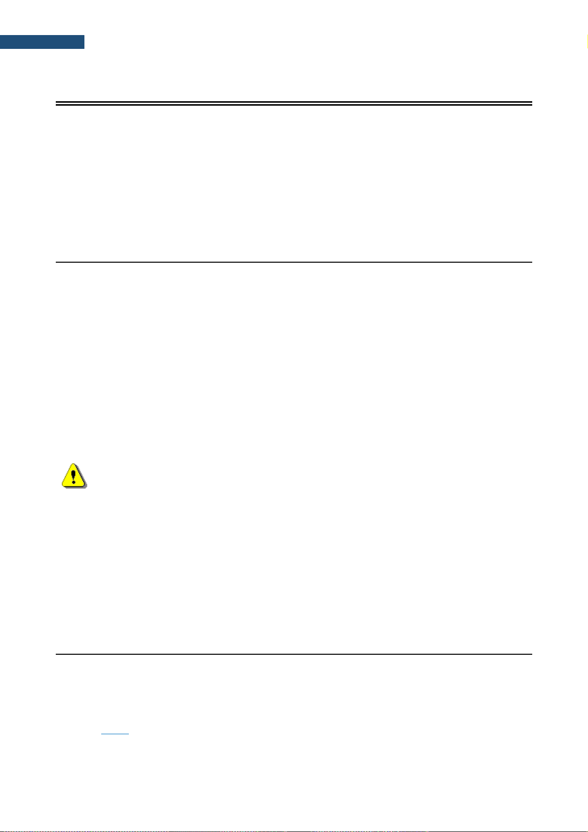
47
SV 200A User Manual
6 REMOTE COMMUNICATION
SV 200A is equipped with three modules that can maintain remote communication with the instrument:
• GSM modem (3G),
• WLAN/ LAN module and
• Bluetooth module.
There is dedicated software that supports remote communication with SV 200A:
• SvanPC++_RC for remote configuration, remote control, data retrieving and data processing,
• SvanNET web-service for remote control and data retrieving,
• Svannet App for remote communication configuration.
6.1 MAIN COMMUNICATION CHANNEL
Main communication channel is the TCP/IP connection (a lossless data exchange protocol) that can be used
to exchange commands as specified by Appendix A to SV 200A User Manual. SvanPC++ assures this
connection and provides data download, configuration, performance validation and measurement start/stop.
Main communication channel of SV 200A can be established by one of two available methods: TCP/IP Client
or TCP/IP Server. The SV 200A stations firmware version 1.03.4 does not support SSL (Secure Socket
Layer) connections.
The TCP Client is a mode of main communication channel in which SV 200A is configured to initiate
connection to a designated address (remote host). SV 200A attempts to establish a TCP/IP connection to a
designated address on a designated port (Data Port) automatically. Should the connection be established
successfully, SV 200A can exchange commands with the remote server. Should the connection attempt fail
or is broken by the remote host, SV 200A will attempt to reconnect again. To prevent the connections from
going idle (a state in which the TCP/IP connection seems to be active, but no data can be transferred), the
station maintains the connection to the server by sending small packages of data at keep alive period (which
by default is one minute). If the transfer is not properly acknowledged by the other party, the connection will
be terminated.
Note: TCP Client mode is used in the SvanNET web-service. SvanPC++_RC supports all
modes of TCP/IP connection.
SV 200A uses the TCP Client mode to connect to SvanNET (this is the default setting of the station) or
another user defined server. The user also connects to SvanNET via web browser or SvanPC ++, and the
service creates a "bridge" between the station and the user. In this case for 3G communication there are no
restrictions on the SIM-card tariff (no public IP address is required) and simple internet access is enough.
The essence of SvanNET is to simplify the procedures and requirements necessary for the connection.
TCP Server is a mode in which SV 200A is configured to act as a server for incoming connections. SV 200A
is waiting for the first connection to be established on a designated port (called Data Port; default 8000).
Such connection can come from any application - an initiator of the TCP/IP connection (such as SvanPC++)
called remote peer. For 3G communication this mode requires the SIM-card with a public address (called
public IP).
6.2 SMS / E-MAIL ALARMING
SMS/E-mail alarming functionality allows SV 200A to inform the user about different events eg. exceeded
thresholds, low battery etc. by SMS and/or E-mail notification. SV 200A can send an SMS to a defined
number(s) and/or an E-mail to a defined address(es) with alarm and its details.
SV 200A has implemented advanced alarm mode. Advanced alarms configuration can be performed using
SvanNET or SvanPC++ application in Station Configuration of the Remote Communication Center (see
Chapter 9.8.12). The E-mail alarming uses SvanNET e-mails feature to send e-mails. The benefits of
SvanNET e-mails is that the user does not required to have any e-mail client account on SMTP server and
that e-mails are SSL encrypted. The content of the message is created automatically.
Page 48

48
SV 200A User Manual
Note: SvanNET e-mail service uses SSL connection.
It should be noted that SMS alarming does not require the internet connection and, as such, the SIM-card
does not require any data transfer plan as sending SMS messages is done entirely over GSM network. Emails still require access to the internet.
6.3 INTERFACE CAPABILITIES OF 3G MODEM
The 3G modem enables a wide spectrum of interfacing capabilities using GSM based internet access. The
3G modem offers the main communication channel, SvanNET e-mail functionalities and SMS alarms
notifications.
6.4 INTERFACE CAPABILITIES OF WLAN/LAN MODULE
SV 200A is equipped with the WLAN/LAN module, which uses a different method of remote connection.
Rather than establishing connection to the internet via GSM operator, it connects directly to Local Area
Network via the Ethernet cable (LAN) or wireless communication (WLAN). The user needs to provide a
networking environment for the instrument to connect to.
The WLAN/LAN module can be configured to work in one of two modes: Wireless (default) or Wired.
Wireless connection requires no cables, although it still needs to remain in close proximity to the devices
(normally 100m at the open area) it is intended to connect with (as per limitation of the wireless connection
protocol). When properly configured, the module will remain connected to the designated network when
powered up. The wireless connection can be set up in two ways: Access Point (default) or Infrastructure.
Access Point connection method allows direct wireless connection to a computer equipped with a wireless
communication module. To establish the connection with SV 200A it is necessary to find the network with
SSID “SV200A_#xxxxx” (xxxxx is a SV 200A serial number) on your PC and connect to it using a password.
Default password is “Svantek”.
Infrastructure connection, rather than being a direct wireless link between the computer and SV 200A,
facilitates a standalone, dedicated device called Access Point to which all wireless devices connect to. This
requires SV 200A to be configured to connect to such Access Point using its SSID (network name) and
security settings. The module will remain connected to the network once properly configured.
Wired connection requires physical link to the LAN network. Upon connection, the WLAN/LAN module will
become a part of the Local Area Network, and all PCs that also are members of the network will be able to
connect to it.
Note: In any given moment, the WLAN/LAN module can only work in Wired or in Wireless
mode. For example, connecting Ethernet cable while the module is configured for Wireless will
have no effect.
The WLAN/LAN module offers main communication channel and SvanNET e-mail functionalities. Details of
the connections’ behaviour depend on the WLAN/LAN settings, allowing the configuration of TCP Server
and TCP Client modes.
In local area network environment (wired or wireless) SV 200A provides a broadcast packet to identify itself
in the network subnet. It uses UDP protocol and port 7000 to send a packet eg.
“#1,U200A,N12345,I192.168.1.1,P8000;” see Appendix A for details about #1 protocol description. The
packet is sent every 5 seconds.
6.5 INTERFACE CAPABILITIES OF BLUETOOTH MODULE
SV 200A has the built-in Bluetooth Low Energy module compliant with the Bluetooth 4.0 standard. Data
exchange between the instrument and external devices is performed using the Bluetooth Low Energy
Svantek proprietary characteristics.
Page 49

49
SV 200A User Manual
7 CONFIGURATION OF THE REMOTE CONNECTION – SVANNET APP
SVANNET APP is a tool that enables automatic configuring the remote connection of your SV 200A with
the SvanNET web-service and SvanPC++.
To start configuration, it is
necessary to connect your
SV 200A to your PC by means of
the USB cable or connect it to the
Access Point with SSID
“SV200A_#xxxxx” and run the
SVANNET APP program.
Note: To have access to SVANNET APP the local SVANTEK distributer should create the
user’s account and assign monitoring stations to it.
After logging, the screen with all connected Svantek instruments will appear.
Select the instrument you wish to connect by clicking on the left-hand box. Some buttons from the right
side will change their colours from grey to blue depending on connection status with the SvanNET webservice. Blue colour means active status of the screen element (button, icon).
If your instrument is not connected to the SvanNET web-service by means of 3G, LAN or WLAN the
Configure button will not be active.
Refresh button is used for searching the stations connected to the PC by USB, WLAN or visible as
Access Point. Searching lasts for 30 seconds and during searching the button is changed to Stop. You
can stop searching at any time by clicking the Stop button.
Page 50

50
SV 200A User Manual
7.1 CONFIGURATION OF THE SV 200A CONNECTIONS
Click on the button and the Remote Connection Settings sidebar will change its
view, offering selection of the connection type: 3G Network (with the use of the 3G modem),
WLAN Infrastructure and LAN Network (with the use of the WLAN/LAN module) and the button that
connects the station to the Internet (Connect to Svannet or Connect to Other Server).
If connection is successful, the button changes its colour to the blue one.
If you click on the button the program will open the SvanNET Configuration section
where you can configure the SV 200A settings.
Page 51

51
SV 200A User Manual
To return to the SVANNET APP press the icon or SVANNET APP logo.
7.1.1 Remote Communication Settings
By default, the 3G Network connection type and the connection to the SvanNet web-service
configuration (Connect to SvanNET) is proposed. After clicking the Show Advanced settings tick box
additional settings will appear.
If the 3G Network connection is selected, advanced
settings will consist of: APN name, APN User name and
APN Password.
If the WLAN Infrastructure connection is selected, the
program will show the list of available WLAN networks.
Page 52

52
SV 200A User Manual
If you click on the selected network, it will drop down
letting you to key in the network Password.
Clicking on the Add Network button you will be able to
define: Service Set Identifier (SSID) and the network
Password.
Clicking on the Show Advanced Settings tick box you
can switch on or off the Dynamic Host Configuration
Protocol (DHCP).
Usually DHCP should be On.
The LAN Network connection doesn’t require any
parameters to configure except Dynamic Host
Configuration Protocol (DHCP), which can be switched
on or off after clicking on the Show Advanced Settings
tick box.
Usually DHCP should be On.
By selecting Other Server, the dropdown menu appears
in which you can select: TCP Server or TCP Client
(Connection mode), remote address for TCP/IP client
connection (Server Address) and Port for this
connection.
.
To set the selected connection press the
button. In case of successful connection, the message
“Settings successfully applied!” appears.
Page 53

53
SV 200A User Manual
7.2 SV 200A SYSTEM CHECK
Click on the button if you wish to
perform the System check.
The System Check pop-up window with the current SPL
result will appear.
Press Start button and SV 200A will pause the running
measurement, switch on the electrostatic actuator,
measure its level and display it in the System Check
pop-up window.
After finishing system checking the current SPL result will
be displayed in the System Check pop-up window with
the message “System Check Successful”.
7.3 ICONS OF SVANNET APP
Other functions of SVANNET APP relate to icons-buttons, located in the upper line of the window.
- returning to the main screen
- opening the SvanPC++ program
- opening the SvanNET web-service
Page 54

54
SV 200A User Manual
- application settings
- exiting SVANNET APP
Icons in the instrument’s line have informative nature. Icon located at the left side of the instrument’s bar
informs about the instrument connection type with the PC:
- USB connection,
- WLAN connection,
- LAN connection,
- Access Point connection.
First icon at the right side of the bar line informs about state of connection with the SvanNET web-service:
- not connected,
- connected.
Second icon at the right side of the bar line informs about connection type with the SvanNET web-service:
- 3G connection,
- WLAN connection,
- LAN connection.
7.4 ADVANCED MODE
If you click on the button the pop-up window
appears in which you can select the Advanced Mode of
this application.
Advanced mode allows in addition to three types of
connection, described earlier, configure the forth one WLAN Access Point connection.
Page 55

55
SV 200A User Manual
If WLAN Access Point connection is selected, in
advanced settings you will be asked to define: service set
identifier (SSID), Password, Security type (Open,
WEP-64bit, WEP-128bit, WPA-PSK or WPA2-PSK) and
the Dynamic Host Configuration Protocol (DHCP).
Usually DHCP should be On.
7.5 OTHER OPTIONS
Other positions in the application settings enable
selecting Multi-Window Mode or Inverse Color Mode.
In the Multi-Window Mode, the SvanNET Configuration
section will appear in the separate window.
The Inverse Color Mode screen is presented below.
Page 56

56
SV 200A User Manual
8 SVANNET WEB-SERVICE
When enabled, and the instrument is properly configured, SvanNET Web-service offers you simple
access to the instrument’s settings, results and status information.
To start use SvanNET the user should browse https://svannet.com and log-in on it.
Note: To have access to the SvanNET web-service the local SVANTEK distributer should
create the user’s account and assign monitoring stations to it.
The SvanNET interface depends on the package of tools assigned to your account and access level and
includes:
– projects tools (Project list)
– individual stations tools (Station list).
If you have extended SvanNET package, you can use both tools. If you have standard SvanNET package,
only Station list tool is available.
Note: This manual describes only the Station list tools. To get more information about Project
list see SvanNET User Manual.
8.1 STATION LIST VIEW
Station list displays all stations assigned to your account – turned on and off. When you click the station,
it becomes active and the tools at the right panel will be dedicated to this particular station.
If the selected station is turned off clicking one of the buttons in the right-side panel you can check the
station status (STATUS) and open three logs: CONNECTION LOG, STATUS LOG and
DATA TRANSFER LOG.
If you click the left field of the grey bar the label with station information appears.
If the selected station is turned on you can additionally open the WEB-interface (by pressing the
WEB INTERFACE button) from which you can control the station and configure it.
Page 57

57
SV 200A User Manual
The station bar except station name with serial number includes five icons that indicate station state.
When station is disconnected from SvanNET all icons are of grey colour.
If you click the station name, station information will be displayed.
If you click the icon, this icon status information will be displayed.
The status icons on the station bar have following meanings:
Warning about emergency situations: blue - everything is OK, red – unregular event is
happening.
Information about the communication with the station: green - correct, in progress; yellow the station doesn’t respond to the command for a long time; red – the station is not
connected to SvanNET.
Battery status. When you click this icon, information about charging level will be displayed.
External power source status: blue – the instrument is powered by the external source, grey
- there is no external power. When you click this icon, information about external source will
be displayed.
Connection status. When you click this icon, information about connection status and signal
strength will be displayed.
The Tool panel provides some functions for station control. To switch the function, point cursor on the
appropriate button (it will change its colour to blue) and click it.
Page 58

58
SV 200A User Manual
The blue STATION LIST button just informs you that you are in
the Station view.
You can set the new station name instead of the default clicking
.
The WEB INTERFACE button switches you to the Live data
view (see Chapter 8.2) in which you can view measurement
results and use additional tools to configure station parameters,
download data files, start/stop measurements and perform
station checking. This button is available for the stations
connected to SvanNET.
The STATUS button switches you to the Station status view
(see Chapter 8.1.1) in which you can check the station status
and configure status alarms.
The STATUS LOG button switches you to the Status log view
(see Chapter 8.1.2) in which you can check the power source
(type and charge level), memory free space, GSM signal quality
and history of system checking.
The CONNECTION LOG button switches you to the Connection log view (see Chapter 8.1.2) in which
you can check the history of station connections.
The DATA TRANSFER LOG button switches you to the Data transfer log view (see Chapter 8.1.2) in
which you can check the history of data transfers (uploads).
8.1.1 STATUS view
In the STATUS view you can check the station status (firmware version, battery charging, memory etc.),
its connection status and configure stations alarms.
• To update instrument’s status, click the UPDATE STATUS button.
• To configure status alarms Conditions and related Actions for the measurement points, click the
STATIONS ALARMS button.
Page 59

59
SV 200A User Manual
Click +Add alarm in the STATIONS STATUS ALARMS pop-up box and new Alarm with CONDITIONS,
ACTIONS and MEASUREMENT POINTS areas will appear. Alarms are based on CONDITIONS and
relate to ACTIONS, that are default e-mails to the specified recipients, and refer to
MEASUREMENT POINTS. To configure Alarm:
1. click the Status button and in the EDIT CONDITIONS pop-up box:
a. select Status source: Mains, External voltage, Battery charge, Storage memory,
System check or other positions,
b. click the Trigger value selector and choose the required threshold level for the selected
Status source.
.
2. click OK and new condition will be displayed
in the CONDITIONS area.
3. click the E-mail button to enter/edit e-mail recipients.
4. click the Assign button to refer alarm to the station(s).
1 2 a
b
Page 60

60
SV 200A User Manual
5. Made selections are displayed in the
ACTIONS and MEASUREMENT
POINTS areas.
8.1.2 LOG views
There are three station logs, that register system events, connections and data transfer:
• Status log which registers power source (type and charge level), memory free space, GSM signal
quality and system check history,
In the upper line you can: refresh the log, select the required period of records to be displayed
and rewind records.
• Data Connection log which registers history of station connections.
In the upper line you can: refresh the log, select the required period of records to be displayed
and rewind records.
• Data transfer log which registers history of data transfers (uploads).
In the upper line you can: refresh the log, select the required period of records to be displayed
and select the period for data transfer presentation: Monthly, Weekly, Daily or Hourly.
3 4 5
Page 61

61
SV 200A User Manual
8.2 WEB INTERFACE VIEW
The WEB INTERFACE view is available for the stations connected to SvanNET and enables:
measurement results viewing, station parameters configuring, data files downloading, measurements
start/stop and station checking.
The VIEW button switches you to the Live data view (see
Chapter 8.2.1) in which you can view broadband results, 1/1 or
1/3-octave spectra and time-history results.
The STATUS button switches you to the station status view (see
Chapter 8.3) in which you can check the station status and
start/stop measurements.
The CONFIGURATION button switches you to the station
Configuration view (see Chapter 8.4.1) in which you can
configure measurement and instrument parameters.
The DATA FILES button switches you to the Storage view (see
Chapter 8.4) in which you can download files manually.
Note: Content of the Configuration tabs depends on the selected parameters. The task of
this manual is not the presentation of all possible combinations of parameters, but an indication
of the principles of working with SvanNET.
8.2.1 Live data view
The Live data view includes three tabs: OVERVIEW, TIME HISTORY RESULTS and
SPECTRUM RESULTS.
The OVERVIEW tab displays current broadband results:
1. Instantaneous Results, measured by 1-second period and
2. Summary Results (Current and Previous) measured in the selected profiles by the
“Integration Time” period.
The map field is used to show the instrument’s position and meteorological data.
Page 62

62
SV 200A User Manual
The Current Summary results are updated every second and present the result measured by
Integration time. The Previous Summary results show result measured by Integration period.
The type of the measured result with the used filter and detector as well as the profile in which this result
is measured is presented in the selector field below the result value. Click the result selector field to
select new profile and measured result:
• for Instantaneous results, you can choose a result from the
list: Lpeak, Lmax, Lmin or Leq.
• for Summary results, you can choose a result from the list:
Lpeak, Lmax, Lmin, LA, Leq, LAE, Lden, LEPd, Ltm3,
Ltm5, OVL and ten statistical level results (Lnn).
Such results as Lpeak, Lmax, Lmin or Leq include in their names
filter abbreviation (A, B or Z) and Lmax, Lmin results include also
detector type abbreviation (F=Fast, S=Slow, I=Impulse).
All measured results are dscribed and formulaes are presented in the
Appendix D to this manual.
Note: The Instantaneous results are not saved in the instrument’s files, while the Summary
results can be saved if the Save summary results option is switched on in the STORAGE tab.
The TIME HISTORY RESULTS tab displays the time history of the selected measurement results.
1
2
Page 63

63
SV 200A User Manual
In this tab you can:
1. Choose results for simultaneous displaying with the use of selector buttons (Leq, Lpeak,
Lmax and Lmin) measured in profiles with weighting filters (A, B, C or Z) and detectors (Fast,
Slow or Impulse).
2. Change the time range for presentation of results.
3. Point your mouse cursor on the plot to readout the values for this time point.
4. Scroll the time window over the time history.
There are four results (Leq, Lpeak, Lmax and
Lmin) measured with appropriate weighting filters
and detector types and available for each
measurement profile from the pop-down list.
The SPECTRUM RESULTS tab displays current 1/1 or 1/3-octave Instant and Averaged results (LZeq)
and three Total results. In this tab, you can:
1. Point your mouse cursor on the plot to readout the values of instantaneous and averaged results
for each 1/1 or 1/3-octave band.
2. Point your mouse cursor on the last three bars of the plot to readout the values of instantaneous
and averaged three Total results.
1
2 3 4
Page 64

64
SV 200A User Manual
Note: Spectra can only be displayed, when the Octave 1/1 or Octave 1/3 measurement
functions has been selected in the Configuration → Measurement setup tab.
8.3 STATUS VIEW
If you click on the STATUS button being in the WEB INTERFACE mode, you will shift to the Status
view which is similar to the above (see Chapter 8.1.1).
Difference is that instead Alarm setting in this view you can start/stop measurements and the actuator
for system checks.
1
2
Page 65

65
SV 200A User Manual
8.4 STORAGE VIEW
If you click the DATA FILES button being in the WEB INTERFACE mode, you will shift to the Storage
view which presents a list of files saved in the instrument’s SD-card memory. The list includes only files
from a single directory on the memory card and it initially shows the content of the current working
directory.
In the Storage window, you can:
1. Download or delete individual files by clicking the righthand icons on the file line
2. Select several files and download or delete selected files
3. Download or delete all files
4. Navigate through the folder structure by clicking the “folder up” button.
1
2
3
4
Page 66

66
SV 200A User Manual
8.4.1 Configuration views
The Configuration view consists of several tabs that enable configuring measurement parameters
(MEASUREMENT SETUP), data saving (STORAGE), export of measurement data into CSV files
(CSV EXPORT), audio recording (AUDIO RECORDING), events triggering (EVENT TRIGGERS),
calibration of the instrument (CALIBRATION), auxiliary settings (AUXILIARY SETTINGS) and
performing the firmware upgrade (FIRMWARE UPGRADE).
To load the new configuration to the station, click the button.
MEASUREMENT SETUP tab
In the MEASUREMENT SETUP tab, you can:
1. Select the Measurement function: Level Meter, Octave 1/1, Octave 1/3
2. Update the Instrument clock
3. Select the type of RMS/Leq Integration: Linear or Exponential
4. Select Filter (Z, A, C) and Detector type (Impulse, Fast, Slow) for profiles
5. Select Filter for the spectrum (position appears when the Octave 1/1 or Octave 1/3 function is
selected).
RMS/Leq Integration defines the detector type for the calculations of the Leq, LEPd, Lnn and SEL
measurement functions. Linear integration is required when you wish to obtain the true RMS value of
the measured signal. When this option is selected the values of the Leq, LEPd, Lnn and SEL functions
do not depend on the detector time constant (Fast, Slow or Impulse), defined for the profiles.
Exponential integration is required in some standards for Leq measurements. When this option is
selected the values of the Leq, LEPd, Lnn and SEL measurement results depend on the detector time
constant (Fast, Slow or Impulse), defined for the profiles.
Such measurement results like Lmax, Lmin, Ltm3 or Ltm5 are always calculated with the Exponential
integration and selected time constants. And vice versa, such results as Lpeak don’t use integration
at all.
1 5 4
3
2
Page 67

67
SV 200A User Manual
Note: Definitions and formulae for measurement functions are presented in Appendix D.
Filter means a frequency weighting filter applied for all measurement results calculated for individual
profiles or for the spectrum:
• Z Class 1 according to IEC 61672-1:2013,
• A Class 1 according to IEC 651 and IEC 61672-1:2013,
• C Class 1 according to IEC 651 and IEC 61672-1:2013,
• B Class 1 according to IEC 651 and IEC 61672-1:2013.
STORAGE tab
In the STORAGE tab, you can:
1. Enable data logging
2. Program splitting of the logger file
3. Configure the Summary results parameters: measurement time and step of saving
(Integration period) and switch on/off saving of statistics (Save statistics)
4. Configure saving of the Time history in a file: step of saving (Step) and selecting the results to
be saved as a Time history for three profiles: Lpeak, Lmax, Lmin and Leq, 1/1 or 1/3-octave
spectra (Save spectrum) and results taken from the weather station (Save meteo).
1 2 3
4
Page 68

68
SV 200A User Manual
The Logger splitting position enables splitting of the time history files and
selecting the splitting mode: Every 15 m, Every 30 m, Every 1 h and
Every day.
If Every day is selected, you
can then define up to six
points during a day when
splitting will take place.
Integration period defines the period during which the signal is being measured
(averaged) and recorded in the file as the set of Summary Results.
The integration period can be selected in the pop-up list in the range from 1s to 24h.
If you switch on the Save statistics button, you can define ten statistical noise levels,
named from L01 to L99, to be calculated, displayed and saved in the file as Summary
results.
Statistical noise level Lnn is a level in dB which was exceeded during nn percent of
the Integration period. Statistical noise levels are calculated from a histogram,
created on the base of 100ms Leq results (see Appendix D).
Note: To ensure saving of Summary results you should switch on the Time history saving,
since Summary results are saved in the same file with Time history results.
Note: All files with measurement result are automatically named in accordance with the rule:
some prefix (string of letters) is added with a number (string of digits) which is increased by one
for the new created files. Default prefix is “L” and it can be changed via SvanPC++.
If the Octave 1/1 or Octave 1/3 function is selected, you can also switch on spectrum saving
(Save spectrum button) as a time history with the same logger Step.
Step can be selected from the row: 10, 20, 50, 100, 200 and 500 milliseconds, from 1 second to 59
seconds, from 1 minute to 59 minutes and 1 hour.
CSV EXPORT tab
The CSV EXPORT tab enables configuring direct export of measurement data into CSV files (Comma
Separated Values) and saving them on the instrument’s SD card.
In this tab, you can:
1. Select results to be exported for each profile individually.
2. Select Maximum, Minimum and Averaged spectra for each integration period if the Octave 1/1
or Octave 1/3 function is enabled.
Page 69

69
SV 200A User Manual
The CSV file structure is presented in the table below.
Section
File contents
File header
// **********************************************************************
// CSV file version, 1.18
// Created, 11/01/2015, 20:43:24
// Unit, 200, SN, 26858
// Firmware, 1.20.7, 14/11/2014
// Corresponding logger file name, L1.SVL
// Device function, SLM
// Integration time, 00:00:01
// Leq integration, linear
// Outdoor filter, environmental
// Profile 1, A, FAST
// Profile 2, C, FAST
// Profile 3, Z, FAST
// Statistical levels, 1, 10, 20, 30, 40, 50, 60, 70, 80, 90
// CSV save mask, 0FFF, 0FFF, 0FFF, 7
// SLM results, profile 1, TIME, PEAK, MAX, MIN, SPL, LEQ, SEL, Lden, Ltm3, Ltm5, Lnn, OVL
// SLM results, profile 2, TIME, PEAK, MAX, MIN, SPL, LEQ, SEL, Lden, Ltm3, Ltm5, Lnn, OVL
// SLM results, profile 3, TIME, PEAK, MAX, MIN, SPL, LEQ, SEL, Lden, Ltm3, Ltm5, Lnn, OVL
// **********************************************************************
Record number
// Record No, 1
Time sgnature
DT, 11/01/2015, 20:43:25
Measurement
data
P1, 1, 56.0, 42.7, 39.6, 42.7, 41.5, 41.5, 46.5, 42.7, 42.7, 42.9, 42.8, 42.6, 42.4, 42.2, 42.0, 41.0, 40.5, 40.0, 38.5, 0
P2, 1, 62.3, 53.9, 47.8, 53.9, 49.8, 49.8, 54.8, 53.9, 53.9, 51.9, 51.5, 51.0, 50.5, 50.0, 49.5, 49.0, 48.5, 48.0, 47.5, 0
P3, 1, 66.7, 59.0, 47.3, 59.0, 57.5, 57.5, 62.5, 59.0, 59.0, 59.9, 59.0, 58.5, 58.0, 57.7, 57.5, 57.2, 57.0, 56.6, 56.3, 0
Record number
// Record No, 2
Time sgnature
DT, 11/01/2015, 20:43:26
Measurement
data
P1, 1, 56.9, 45.4, 41.4, 45.4, 42.8, 42.8, 47.8, 45.4, 45.4, 46.9, 46.0, 43.0, 42.7, 42.5, 42.2, 42.0, 41.6, 41.3, 41.0, 0
P2, 1, 63.3, 52.6, 47.9, 52.6, 50.4, 50.4, 55.4, 52.6, 52.6, 53.9, 53.6, 53.3, 53.0, 48.7, 48.5, 48.2, 48.0, 47.6, 47.3, 0
P3, 1, 67.8, 59.2, 54.0, 59.2, 56.6, 56.6, 61.6, 59.2, 59.2, 59.9, 59.5, 59.0, 57.0, 55.6, 55.3, 55.0, 54.6, 54.3, 54.0, 0
Record number
// Record No, 3
Time sgnature
DT, 11/01/2015, 20:43:27
Measurement
data
P1, 1, 57.6, 41.7, 37.6, 41.7, 39.1, 39.1, 44.1, 41.7, 41.7, 42.9, 42.0, 41.0, 39.0, 38.7, 38.5, 38.2, 38.0, 37.5, 37.0, 0
P2, 1, 62.9, 53.2, 49.6, 53.2, 50.9, 50.9, 55.9, 53.2, 53.2, 54.9, 54.0, 50.8, 50.7, 50.5, 50.4, 50.2, 50.1, 50.0, 49.5, 0
P3, 1, 68.9, 64.0, 56.9, 64.0, 61.9, 61.9, 66.9, 64.0, 64.0, 63.9, 63.6, 63.3, 63.0, 62.0, 61.6, 61.3, 61.0, 60.5, 60.0, 0
…
…
Note: CSV files can be quite large, and it is advised to use this feature when absolutely
necessary.
1
2
Page 70

70
SV 200A User Manual
AUDIO RECORDING tab
In the AUDIO RECORDING tab, you can configure an audio recording, which can be recorded on the
result file together with Time history and Summary results, or in a separate *.wav type file. For this
purpose, switch Type button to Events or Wave.
In this tab you can configure four parameters of audio recording: Format of the file in the case of Wave
recording (PCM or Extensible), Bits per sample (16 or 24), Recording range (from 28 dB – 100 dB
to 68 dB - 140 dB) and Sampling frequency (12kHz, 24kHz and 48kHz).
Choosing of higher sampling rate ensures recording of higher frequencies but at the same time
increases file size.
The audio recording trigger is configured in the EVENT TRIGGERS tab.
EVENT TRIGGERS tab
In the EVENT TRIGGERS tab, you can configure events for triggering markers, audio recording and
alarms.
1. Events are specified as a combination of superimposed CONDITIONS (logical AND) such as
specific time intervals (Time periods) in which measurement threshold levels are exceed or
system events occur (Triggers).
2. Each Event may be connected with special triggers (Actions) such as: marker recording to the
logger file (MARKER), audio signal recording to the logger file or wave file (AUDIO), generation
of the alarm signal on the I/O socket (I/O ALARM), alarm SMS sending (SMS ALARM) or alarm
e-mail sending (E-MAIL ALARM).
3. Switch off the Event without deleting it. The Event becomes inactive, but you can switch it on
when needed.
Page 71

71
SV 200A User Manual
Creating Events
To create new event, click the field. The new Event area will appear in which you can:
1. rename the event, switch it on/off or delete it, clicking on the appropriate field in the area,
2. configure conditions, clicking on the appropriate button.
If you click the TIME PERIODS button the
TIME CONDITION configuration box will pop-up.
In this box, you can select days and periods for events
registration.
After confirmation (OK) the pop-up box closes, and the selection will be presented in the line of the
TIME PERIODS button.
1
2
3 1 2
Page 72

72
SV 200A User Manual
If you click the TRIGGER button, the TRIGGER
CONDITIONS configuration box will pop-up.
In this box, you can add the condition type: Threshold,
Spectrum, Meteo and System.
The Threshold condition can be of
Level+ or Level- type (Mode). The
condition is fulfilled during the
period in which the controlled
value of the selected result
(Source) will be higher/lower than
the Threshold level.
You can select as a Source different results (Leq, Lpeak, Lmax, Lmin, etc.) for
three profiles (Pr 1, Pr 2 and Pr 3), measured by: 1s, integration period (for
example, 1m, SR) or time-history step (for example, 50, TH).
In the right-hand example, 1m, SR means that the Integration period for the
Summary results was set to 1 minute, while 50, TH means that the Step for the
time-history was set to 50 milliseconds.
If you expand the Threshold by
clicking the field, you
can define Start and Stop
threshold levels and delays
(Min. duration) of start and stop.
After confirmation (OK) the pop-up box closes, and the selection will be presented in the line of the
TRIGGER button.
Page 73

73
SV 200A User Manual
In the SPECTRUM CONDITION
pop-up box, you can define a mask
for thirty one 1/3 octave bands
spectrum and three Total results. If
the measured spectrum
(AVERAGED, INSTANT, MAX or
MIN) will show the excess of the
levels (Level + Mode) or the
lowering of the levels (Level -
Mode) defined for the mask, then
the condition will be active during
Min. duration time.
To start mask creation, click the
field and select the
spectrum frequency or the Total
result.
Then select the threshold level for
that frequency/Total in the
Thresholds position.
After confirmation (OK) the pop-up box closes, and the selection will be presented in the line of the
TRIGGER button.
The Meteo condition is similar to
the Threshold one and can be of
Level+ or Level- type (Mode) and
defines period during which the
controlled value of the selected
result (Source) will be
higher/lower than the Threshold
level.
You can select as a Source different results (Max wind, Avg wind and Rain)
measured by: 1s, Summary results Integration period (for example, 1m, SR) or
Time History step (for example, 50, TH).
In the right-hand example, 1m, SR means that the Integration period was set to 1
minute, while 50, TH means that the Step for the Time-history was set to 50
milliseconds.
Page 74

74
SV 200A User Manual
After confirmation (OK) the pop-up box closes, and the selection will be presented in the line of the
TRIGGER button.
In the SYSTEM CONDITION pop-up box, you can
select conditions that describe behaviour of the
system, such as: Low battery, Low storage space
etc.; and define duration during which these
conditions will be active (Min. duration).
The Min. duration parameter defines minimum time
during which the Condition is active. If during this
time the new condition will be fixed, the duration will
be prolonged to another Min. duration time and so
on.
After confirmation (OK) the pop-up box closes, and the selection will be presented in the line of the
TRIGGER button.
You can select several Trigger conditions for the
Event.
All conditions have the AND logic, e.g. are
superimposed.
After confirmation (OK) the pop-up box closes, and the selection will be presented in the line of the
TRIGGER button.
Page 75

75
SV 200A User Manual
Creating Actions
To create new action, click the field and in
the ADD EVENT ACTION pop-up box, click the action
you wish to add and to configure: Marker, Audio,
I/O alarm, SMS alarm or E-mail alarm.
After occurrence of the event, actions will be
performed during the time the event is active, at its
beginning or at the end depending on the action type.
The Marker action registers a marker in the logger file.
The Marker can be Point or Block type. The Point
marker means, that it will be registered only at the
beginning of the Event. The Block marker will be
registered at the beginning and at the end of the
Event.
The Audio action starts an audio recording in the
logger file (Event recording) or in the WAV type file
(Wave recording).
Max. duration defines maximum time of recording
after the event start.
Min. break defines the minimum time break between
two consequent records.
Pre trigger enables earlier start of recording with
respect to the event start.
The period of such recording depends on the sample frequency and bits per sample. The maximum pretrigger period is:
• for 24 bits per sample: 5s for 48 kHz, 10s for 24 kHz and 20s for 12 kHz.
• for 16 bits per sample: 8s for 48 kHz, 15s for 24 kHz and 30s for 12 kHz.
The I/O alarm action starts an alarm signal at the
MULTI I/O socket output to which some alarm device
can be connected (for example, alarm lamp).
Max. duration defines maximum time of alarm signal
after the event start.
Min. break defines the minimum time break between
two consequent alarms.
The SMS alarm action sends the SMS note to the
defined recipient’s phones, which are selected from
the ADDRESS BOOK.
Min. break defines the minimum time break between
two consequent SMSs.
The SMS text is generated automatically in
accordance with the event definition.
Page 76

76
SV 200A User Manual
The E-mail alarm action sends the E-mail note to the
defined recipient’s addresses, which are selected from
the ADDRESS BOOK.
Min. break defines the minimum time break between
two consequent E-mails.
The E-mail text is generated automatically in
accordance with the event definition.
After confirmation (OK) the pop-up window closes, and the selection will be presented in the lines of the
appropriate button of the Actions section.
Address book
The ADDRESS BOOK pop-up window appears in the
SMS and E-mail alarm actions pop-up windows when
you click on the field.
In this case you should select the required address
and click OK.
You can add the contact by clicking on the
field.
You can Edit address book from the
EVENT TRIGGER tab of the Configuration view.
CALIBRATION tab
In the CALIBRATION tab, you can:
1. Switch on the Auto calibration function,
2. Define the Maximum calibration log size in MB,
3. Switch on the Automatic system check (Enabled button) and
4. Set time and days of the week when system check is going to be performed,
5. Manually Perform system check now.
Page 77

77
SV 200A User Manual
When the Automatic system check feature is enabled the calibration factor of the instrument will be
periodically verified using built-in electrostatic actuator.
Note: System check cannot be considered as a calibration. Calibration factor will not be
updated during Automatic system check procedure.
AUXILIARY SETTINGS tab
1
2
3 4 5 1 2
3
Page 78

78
SV 200A User Manual
In the AUXILIARY SETTINGS tab, you can:
1. enter Station description: Station name, Project name and Location name,
2. enter the instrument’s geographical location in Latitude and Longitude coordinates (if GPS is
switched on),
3. select the External device: weather station (Meteo-SP 275), GPS or User interface.
8.4.2 FIRMWARE UPGRADE tab
In the FIRMWARE UPGRADE tab, you can upload new firmware on the instrument’s SD card and
perform upgrade process remotely.
Complete upgrade process is described in detail in Chapter 11.2. Before upgrading it is essential that
the proper firmware file is downloaded from SVANTEK website.
Page 79

79
SV 200A User Manual
9 SVANPC++ SOFTWARE
SV 200A can be fully controlled via SvanPC++ software, which provides also wide spectrum of data
post-processing and reporting functions.
Note: All SvanPC++ functions are well described in the SvanPC++ User Manual. In the
current manual only most useful and instrument specific functions and screens are
described.
SV 200A needs to be connected to the computer running SVAN PC++ either by USB cable, 3G, WLAN
or LAN connection. In all cases except USB, SvanPC++ should be supplemented with the Remote
Communication module.
9.1 SVANPC++ SOFTWARE INSTALLATION AND ACTIVATION
To configure SV 200A for the first time the user should use Svan PC++ software on your PC. It allows
easy control of each function of the instrument and manage whole noise monitoring station systems
consisting of more than one SV 200A device.
1. Make sure that your PC has active Internet connection if you wish to use SV 200A via the
Internet. PC should have Windows operating system. Minimum system requirements: 1GHz
CPU, 1 GB RAM (2GB RAM for x64 system), 20 GB HDD, 1024x768 display.
2. Download and install Svan PC++ software and Svantek USB Drivers from
http://svantek.com/lang-en/support/software.html.
3. Prepare the activation key for the Remote Communication (RC) module, that has been
provided with the device.
4. On the Help menu click Enter Activation Keys… option and enter the key to activate the
Remote Communication module.
5. Your Svan PC++ software is ready to use with SV 200A.
Note: Remote Communication module should be activated for each individual SVANTEK
device. Remember to enter activation key for any new device you wish to manage with the
RC module.
9.2 SV 200A CONTROL VIA USB INTERFACE
Although SV 200A is dedicated to wireless remote control it can be also easily configured and controlled
via the USB interface. The USB interface or WLAN in AP mode should be used for the first wireless
communication configuration. The USB interface can also be used in emergency, when wireless
connection was broken or when for some reason wireless communication is not possible or in situations
when the measurement process doesn’t require wireless control of the instrument.
The philosophy of the instrument control from SvanPC++ either via USB or via wireless communication
is generally the same. Therefore, this manual will be concentrated mostly on wireless instrument control.
After connecting the instrument to the computer with running Svan PC++ by SC 256A USB cable the
SV 200 instrument wizard window appears on the screen. It enables you to:
Page 80

80
SV 200A User Manual
• Manage the instrument remotely
(Remote Connection Center button)
• Manage the instruments’ file structure
(SVAN files button)
• Unload, upload and edit the instrument’s setup
files (Setup editor button)
• Set the instruments’ real time clock to be equal
with computer clock (Update RTC button)
• Calibrate the instrument (Calibration button)
• Check the firmware updates
(Check for Updates button)
After pressing the Remote Communication Center button, the Remote Communication Center
panel, which assures full instrument control, will appear.
9.3 CONFIGURING WIRELESS CONNECTION
SV 200A is equipped with internal 3G modem and LAN/WLAN module which enable wireless remote
control of the instrument and downloading measurement files, managing configuration, sending alarm
e-mails, etc. To access SV 200A remotely, the instrument first must be properly configured via the USB
connection.
All types of connections can be configured via SV 200A instrument wizard, which is described below,
or via the Remote communication tab (see Chapter 9.8.9) in the Station(s) configuration section.
Page 81

81
SV 200A User Manual
Note: SVANTEK does not provide a SIM-card for the instrument. It is necessary to purchase
the SIM-card with data plan. If the instrument is intended for constant monitoring, choose
service provider that ensures good reception at the measurement point.
Note: Make sure the SIM-card has deactivated PIN-code before insertion into SV 200A.
1. Connect the instrument to the PC with the SC 256A USB cable.
2. In the SV 200A instrument wizard window, click the Remote Connection using SvanNET
button or right-hand button which opens the pop-up list of other connections configurations. The
Remote Connection using SvanNET button enables creating and managing connection with
the SvanNET web-service, easiest way of remote control of all type of stations with 3G modems
and any type of SIM-card credentials.
3. Every position opens the Remote Connection Wizard window in which you can add new
station. First position opens the same window that the Remote Connection using SvanNET
button. All Remote Connection Wizard windows are well self-described, so you should only fill
the required fields based on the GSM provider information.
4. After entering all the required information
SvanPC++ will check connection
settings. Wait until process is finished. It
may take few minutes.
Page 82

82
SV 200A User Manual
5. After finishing configuration, you can exit
the wizard or add another instrument.
9.3.1 Connections via 3G modem
As was said above the Remote Connection using SvanNET mode is the simplest way to install
wireless communication. All other modes require more efforts and are not recommended by the
producer. If you wish to use other modes, you must refer to the SvanPC++ User Manual for details.
You can enter Station name and Station description for easy instrument identification after the wizard
is finished. APN is mandatory field required to set up the connection. APN value is specific for each
mobile operator, who should deliver such information.
After filling in the required fields in the Remote Connection Wizard, press the Next>> button and enter
the login and the password of your registered account.
Press the OK button and SvanPC++ will run connection settings (step 4 of above procedure).
9.4 CONNECTING TO THE STATION
1. Open the Remote Communication Center window in SVAN PC++.
Page 83

83
SV 200A User Manual
or
2. Make sure that suitable Connection type is chosen. The default connection type is Internet,
however when the instrument is connected to the PC by the USB cable, connection type is
automatically changed to USB.
3. Choose the instrument in the station list.
4. Click Station configuration button.
9.5 STARTING MEASUREMENTS
Note: SV 200A provides AutoStart feature. If the instrument is idle for 60 s the
measurement is automatically started. The AutoStart function is inactive in the case: USB
is connected, or logging is switched off.
To start the measurement, perform next steps:
1. Make sure that the instrument is turned on.
2. Open Remote Communication Center.
3. Make sure appropriate Connection type is selected. If you wish to communicate with the
instrument via the 3G, WLAN or LAN connection, select Internet. If you wish to communicate
with the instrument via the USB cable, select USB.
4. Select the station in the Station list box.
5. Check the state of the instrument by clicking Check instrument(s) status. When the instrument
status is known, the Start measurement button becomes enabled.
6. Click the Start measurement button.
Connection type box
Station list
Check instrument
status button
Start
measurement
button
Page 84

84
SV 200A User Manual
9.6 VIEWING LIVE RESULTS
It is possible to observe live results. For this:
1. Click on the Live results preview button on the Remote Communication Center panel.
2. Click on the Configure results button to select results for viewing in the
WWW & Live Results / FTP Selection window and return to the Live Results window by
clicking the OK button. Then press the Start button in the Live Results window to start results
presentation.
In the Live Results window, you can also:
1. change the step of data readout (Read step button),
2. start or stop measurements (Start Measurement / Stop Measurement button),
Viewing results
configuration
button
Actuator enabling
button
Page 85

85
SV 200A User Manual
3. view system log information (Show log button),
4. terminate the Live view session (Terminate button),
5. enable the SV 200A actuator and perform the instrument’s check (Enable Actuator button).
After enabling the actuator, the instrument starts measuring of the signal, generated by the actuator at
the level of 94 dB. If Read step is equal to 1s then it is possible to observe the measured actuator level.
9.7 CHANGING THE WORKING DIRECTORY
Working directory is a folder on the SD-card in which all the measurement files are stored.
Changing the working directory can be done with the SVAN Files feature of the SvanPC++ software
either via SV 200 Instrument wizard or via Remote Communication Center.
1. Make sure a measurement is not in progress.
2. Open the SVAN Files window and navigate to the desired directory using the left panel. The left
panel displays contents of the instrument’s memory. Create a new directory if necessary.
SVAN Files button
SVAN Files button
Page 86

86
SV 200A User Manual
1. Click the Set as working directory
button.
2. Working directory of SV 200A is now
set. All result files will be stored in the
selected directory.
9.8 STATION CONFIGURATION
To configure the station or measurement parameters:
1. Activate Remote Communication Center panel
2. Select the Internet or USB connection type
3. Select the station from the Station list and
4. Press the Station configuration button.
Set as working directory
Content of
instruments
memory
Create new directory
Go to parent directory
Go to working directory
Connection type box
Station configuration button
Stations list
Page 87

87
SV 200A User Manual
5. Wait until instrument’s settings are
downloaded, which will be signalized by
Success written in the last line of the Reading
Settings… box. Click OK to proceed.
6. Station(s) configuration window will appear. It allows the user to modify general instrument
settings, measurement setup, external I/O setup, internet services and system events settings.
Remote communication setup is available only for USB connection.
Note: The Station(s) configuration window enables configuring only general instrument
settings. The SVAN Files window with the use of Svan file editor function enables the
full range of settings – see “SvanPC++ User Manual”.
9.8.1 General settings
In the General settings tab, you can enter Name and Comment to the station. This can be useful while
using many measurement devices.
Note: Name appears on the Station list of the SvanNET web-service.
9.8.2 Measurement setup
The Measurement setup tab consists of the following parameters: measurement function (Function:
Level meter, 1/1 Octave or 1/3 Octave), delay of the measurement start (Start delay), integration
period/measurement run time (Integration period: INFINITE, 1 s ÷ 24 h), RMS detector type
Page 88

88
SV 200A User Manual
(RMS integration), number of repetitions of measurement cycles (Repetition cycles), microphone
compensation (Outdoor filter) and configuration of channels input (Channels config), which in the
case of SV 200A is set to sound measurement (SLM) and cannot be changed.
Measurement function
The main function of the instrument is the measurement of Sound pressure broad band level
(Level meter). The Level meter function provides you with functions meeting the standard IEC 616721:2013 for class 1 accuracy.
You may also use 1/1 and 1/3 real time octave band
frequency analysis (1/1 Octave and 1/3 Octave). These
functions extend the main Level Meter functions of the
instrument, because the selected 1/1 and 1/3 octave analysis
is performed along with all calculations of Level Meter.
Start delay
The Start delay position defines the delay period from the
moment of clicking the Start measurements button to the
measurement start (digital filters of the instrument constantly
analyse the input signal even when the measurement is
stopped). This delay period can be set from 0 s to 60 s.
Page 89
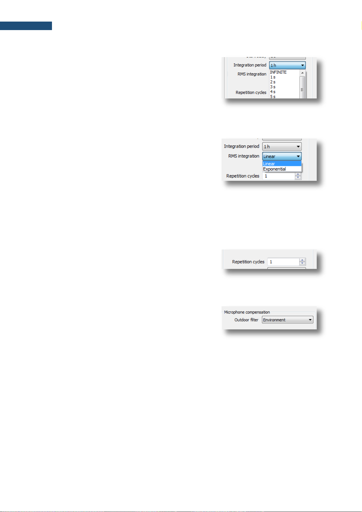
89
SV 200A User Manual
Integration period
The Integration Period position defines the period during
which the signal is being measured (averaged) and
measured results stored as the set of Summary Results.
The measurement will stop automatically after this period.
When the Repetition cycle is greater than one, the
measurement will start again.
When INFINITE is selected, the measurement will run until
the user stops it manually.
RMS Integration
The RMS Integration position defines the detector type for
calculation of the Leq, LEPd, Lnn and SEL results. Two
options are available: Linear and Exponential. The
formulae used for results calculation are given in
Appendix D.
The Linear integration is used when it is required to obtain
the true RMS value of the measured signal. When this option
is selected the value of the Leq, LEPd, Lnn and SEL results
do not depend on the detector time constant: Fast, Slow or
Impulse.
The Exponential integration enables fulfilling the requirements of other standards for the time averaged
Leq measurements. When this option is selected value of the Leq, LEPd, Lnn and SEL functions depends
on the detector time constant: Fast, Slow or Impulse.
Repetition cycles
The Repetition cycles position defines the number of cycles
(with the measurement period defined by
Integration Period) to be performed by the instrument. The
Repetition cycles number values are within limits
[INFINITE, 1, 1000]. INFINITE means that the instrument will
repeat the measurements until it will be stopped manually.
Outdoor filter
The Outdoor filter setting enables selecting the appropriate
compensation filter. The characteristics of the outdoor filter
depend on the application: Environment (acoustic signal is
parallel to the microphone’s grid) or Airport (acoustic signal
is perpendicular to the microphone’s grid). The frequency
characteristics of the filters are given in Appendix C.
9.8.3 Channels
In this tab, filter and RMS detector can be selected for each acoustic profile individually. Due to this,
three results with different filter and detector can be obtained simultaneously. When 1/1 Octave or 1/3
Octave functions are selected, frequency weighting filter for 1/1 & 1/3 octave analysis can also be
defined.
Page 90

90
SV 200A User Manual
Weighting filter
• Z class 1 according to IEC 61672-1:2013,
• A class 1 according to IEC 61672-1:2013 and
IEC 651,
• C class 1 according to IEC 61672-1:2013 and
IEC 651,
• B class 1 according to IEC 651.
RMS detector
The following RMS detectors are available in the instrument:
Impulse, Fast and Slow.
9.8.4 Logger settings
This tab enables setting the logger function, e.g. recording of the time history of measured results, and
consists of the following parameters: time history activation (Logger On), time history step
(Logger step), activation of recording of parameters taken from meteorological station (Logger meteo),
splitting of logger records (Splitting Mode) and logged results selection.
Detector & filter settings
Spectrum filter setting
Page 91

91
SV 200A User Manual
Time history results are saved in a file with automatically defined name, which consists of a prefix (a
string of letters) and a number (string of digits). New time history is recorded in a new file, which name
is generated on the inherit principle – new file name has the same prefix as the previous file, but it’s
number is increasing by one.
Note: The Station(s) configuration window doesn’t allow changing names of the logger
files. But you can do it in the SVAN Files window with the help of the Setup file editor
function – see “SvanPC++ User Manual”.
Logger On
The Logger On position switches on/off the functionality,
which enables saving selected results from three user profiles
with the Logger step and Summary results with the step
specified by the Integration period parameter.
Note: When Logger On is deselected, no measurement results will be stored in the
SV 200A memory. Usually this setting should be on.
Logger step
The Logger step defines the period of logger results
integration/measurement and logging in the logger file. It can
be set from 2 milliseconds to 1 second in 1, 2, 5 sequences,
from 1 second to 59 second, from 1 minute to 59 minutes and
1 hour.
Logger meteo
The Logger meteo check-box controls saving results from
the SP 275 weather station (supplied as an option). The
results are saved with the Logger step period, unless it is
smaller than 1s. In such case, weather data will be stored in
the result file each second.
Page 92

92
SV 200A User Manual
SP 275 enables recording humidity, pressure, temperature, wind speed and direction values as well as
rain and hail intensity.
Splitting mode
The Splitting mode selector enables choosing maximum
length of each partial results file. If in the moment of splitting
the measurement is still carried out, the partial results file is
closed, and the results are saved in the next partial results file.
At specific time option splits files at a specified time of a day.
It is possible to define up to six settings.
Logger results
The Logger Results list enables selecting the results for
three independent user defined profiles, which will be
recorded to the logger file during the measurement.
Measurement parameters for each profile are defined in the
Channels section.
9.8.5 Event recording
The Event Recording functionality enables activating event waveform signal recording in the
instrument’s memory and setting recording parameters.
Recording type
The Recording type position enables choosing the way
the recording is going to be stored.
Wave recording will be stored on the SD-card in form of a
separate PCM (*.wav) file along with logger files.
Event recording will be stored inside logger files. Audio
recording in a logger file is indicated as an Audio marker.
Recording settings
Trigger settings
Page 93

93
SV 200A User Manual
The event recording can be later exported from the logger
file to the PCM format.
Wave recording results are saved in a file with automatically defined name, which consists of a prefix (a
string of letters) and a number (string of digits). Name of the new Wave file is generated on the inherit
principle – new file name has the same prefix as the previous file, but it’s number is increasing by one.
Note: The Station(s) configuration window doesn’t allow to change the name of the Wave
files. But you can do it in the SVAN Files window with the help of Setup file editor function
– see “SvanPC++ User Manual”.
Note: PCM audio recordings take up a lot of storage space and also transmission bandwidth
during data downloading.
Recording settings
The Recording settings section enables choosing a sampling frequency and a format (only available
in the Wave recording mode) of the recording.
It is possible to select one of the three sampling rates: 12 kHz, 24 kHz or 48 kHz. Higher sampling rate
ensures recording of higher resolution but at the same time increases file size.
The Format position enables selecting the format of the
recorded file: PCM or Extensible.
The Bits per sample position enables selecting 16 or 24 bits
per sample.
Trigger parameters
The Event Trigger position enables selecting the recording
trigger type.
Triggering is switched on if one of its seven available types is
selected: Continuous, Slope +, Slope –, Level +, Level –,
Gradient + or Integration period (see Chapter 8.4.1).
When the Continuous trigger is active, whole measurements
will be recorded.
9.8.6 CSV export
The CSV export functionality allows direct export of measurement data into CSV files stored on the
instrument’s SD-card. The Current results tab enables selecting results to be exported from each
profile individually. Maximum, minimum and average spectra for each integration period can also be
exported.
Page 94

94
SV 200A User Manual
The file structure of a generated CSV is shown in the table below.
Section
File contents
File header
// **********************************************************************
// CSV file version, 1.18
// Created, 11/01/2015, 20:43:24
// Unit, 200, SN, 26858
// Firmware, 1.20.7, 14/11/2014
// Corresponding logger file name, L1.SVL
// Device function, SLM
// Integration time, 00:00:01
// Leq integration, linear
// Outdoor filter, environmental
// Profile 1, A, FAST
// Profile 2, C, FAST
// Profile 3, Z, FAST
// Statistical levels, 1, 10, 20, 30, 40, 50, 60, 70, 80, 90
// CSV save mask, 0FFF, 0FFF, 0FFF, 7
// SLM results, profile 1, TIME, PEAK, MAX, MIN, SPL, LEQ, SEL, Lden, Ltm3, Ltm5, Lnn, OVL
// SLM results, profile 2, TIME, PEAK, MAX, MIN, SPL, LEQ, SEL, Lden, Ltm3, Ltm5, Lnn, OVL
// SLM results, profile 3, TIME, PEAK, MAX, MIN, SPL, LEQ, SEL, Lden, Ltm3, Ltm5, Lnn, OVL
// **********************************************************************
Record number
// Record No, 1
Time sgnature
DT, 11/01/2015, 20:43:25
Measurement
data
P1, 1, 56.0, 42.7, 39.6, 42.7, 41.5, 41.5, 46.5, 42.7, 42.7, 42.9, 42.8, 42.6, 42.4, 42.2, 42.0, 41.0, 40.5, 40.0, 38.5, 0
P2, 1, 62.3, 53.9, 47.8, 53.9, 49.8, 49.8, 54.8, 53.9, 53.9, 51.9, 51.5, 51.0, 50.5, 50.0, 49.5, 49.0, 48.5, 48.0, 47.5, 0
P3, 1, 66.7, 59.0, 47.3, 59.0, 57.5, 57.5, 62.5, 59.0, 59.0, 59.9, 59.0, 58.5, 58.0, 57.7, 57.5, 57.2, 57.0, 56.6, 56.3, 0
Record number
// Record No, 2
Time sgnature
DT, 11/01/2015, 20:43:26
Measurement
data
P1, 1, 56.9, 45.4, 41.4, 45.4, 42.8, 42.8, 47.8, 45.4, 45.4, 46.9, 46.0, 43.0, 42.7, 42.5, 42.2, 42.0, 41.6, 41.3, 41.0, 0
P2, 1, 63.3, 52.6, 47.9, 52.6, 50.4, 50.4, 55.4, 52.6, 52.6, 53.9, 53.6, 53.3, 53.0, 48.7, 48.5, 48.2, 48.0, 47.6, 47.3, 0
P3, 1, 67.8, 59.2, 54.0, 59.2, 56.6, 56.6, 61.6, 59.2, 59.2, 59.9, 59.5, 59.0, 57.0, 55.6, 55.3, 55.0, 54.6, 54.3, 54.0, 0
Record number
// Record No, 3
Time sgnature
DT, 11/01/2015, 20:43:27
Measurement
data
P1, 1, 57.6, 41.7, 37.6, 41.7, 39.1, 39.1, 44.1, 41.7, 41.7, 42.9, 42.0, 41.0, 39.0, 38.7, 38.5, 38.2, 38.0, 37.5, 37.0, 0
P2, 1, 62.9, 53.2, 49.6, 53.2, 50.9, 50.9, 55.9, 53.2, 53.2, 54.9, 54.0, 50.8, 50.7, 50.5, 50.4, 50.2, 50.1, 50.0, 49.5, 0
P3, 1, 68.9, 64.0, 56.9, 64.0, 61.9, 61.9, 66.9, 64.0, 64.0, 63.9, 63.6, 63.3, 63.0, 62.0, 61.6, 61.3, 61.0, 60.5, 60.0, 0
…
…
Note: CSV files take up a lot of storage space and transmission bandwidth during data
downloading.
Result selector
Page 95

95
SV 200A User Manual
9.8.7 Advanced settings
The Advanced settings tab enables defining ten statistical levels, named from N1 to N10, to be
calculated and saved in the results files.
All values must be in the integer range of 1 to 99. Each value can be set independently from the others.
9.8.8 External I/O
The External I/O tab allows you to select the device connected to SV 200A via the MULTI I/O socket.
The External device selector list contains devices that are connected via the MULTI I/O socket.
• RS 232 Interface,
• Meteo-SP 275 denotes SP 275 meteo module.
Selecting either one of the devices alters the content of positions for the selected external device.
The RS 232 Interface configuration requires setting two
additional parameters: Baud rate and Timeout.
The Meteo option requires setting the number of Wind
statistics sectors.
Wind statistics include wind direction, maximum wind speed
and average wind speed distributions.
Statistics selector
Page 96

96
SV 200A User Manual
9.8.9 Remote communication
The Remote communication tab enables configuring a remote communication with SV 200A via 3G
or WLAN/LAN. Also, some other additional functions can be configured in this tab: Bluetooth, GPS and
energy saving by means of switching off powering of modems or enabling powering during defined time
window.
Note: Use this tab carefully, because if you make improper changings and send new
settings to your SV 200A, your Internet connection may not work. And what is worse you
will not be able to change settings remotely!
The connection configuration can be also done through the Instrument wizard panel (see Chapter 9.3).
The Remote communication tab allows configuring all communication types in one place.
GSM Modem configuration
Connection mode defines the type of TCP/IP connection:
TCP server or TCP client. If it is None, there is no
connection with the Internet.
Typical GSM Modem configuration for connection with the
SvanNET web-service is presented right-hand.
Other configurations are dedicated to the specific user
needs or GSM operator conditions in some countries
(please refer your local GSM operator for details).
WLAN/LAN connection
configuration
3G connection configuration
Page 97

97
SV 200A User Manual
LAN / WLAN Modem configuration
Configuration of the WLAN/LAN module should start from
selection of the Interface type:
• Disabled means that WLAN/LAN module is switched
off.
• Wired means that SV 200A should be connected to the
Local Area Network (LAN) via the SP 200 adapter,
connected to the LAN socket.
• Wireless Infrastructure means that SV 200A should
be connected to the existing wireless network.
• Wireless Access point means that SV 200A should
work as a wireless router.
Typical Wireless Infrastructure configuration for
connection with the SvanNET web-service is presented
right-hand.
Other settings are dedicated to the specific user needs and
should be configured by local IT specialist.
Network (SSID), Security and Password positions should
be configured based on used wireless network specific
parameters.
9.8.10 Time synchronization
SV 200A offers sophisticated time synchronization features, including automatic and manual daylightsaving time adjustments.
In the Time zone settings section you can select suitable
Time zone and Daylight Saving Time Standard.
European and US/Canadian standards are implemented
in the instrument.
Time zone settings
Custom daylight saving
time setting
Page 98

98
SV 200A User Manual
If different daylight-saving time rules should be applied,
select Custom and fill in Custom Daylight Saving Time
section.
Note: There are four time-synchronization servers predefined in Time synchronization
settings. Do not change these settings unless the servers are unavailable in the
instrument’s network or a custom server is needed.
9.8.11 Calibration & System Check
SV 200A is fitted with an Automatic calibration and Automatic system check features. The
Calibration & System Check section enables configuring these features.
Automatic calibration
When the Automatic calibration is enabled, mounting on the instrument’s microphone and switching
on the sound calibrator automatically starts the calibration procedure.
Such operation requires typing the Calibration Level from the calibration certificate of the used
calibrator. For more information about the automatic calibration feature see Chapter 4.2.
Note: Defined Calibration Level remains constant. Remember to perform calibration with
the sound calibrator generating the same level as the configured calibration level.
Automatic calibration
settings
Automatic system
check settings
Page 99

99
SV 200A User Manual
Automatic system check
When the Automatic system check feature is enabled the calibration factor of the instrument will be
periodically verified using built-in electrostatic actuator. You can specify the hour and a weekday of the
automatic system checks.
To activate the automatic system check, select Enabled (no Cal. Factor update) option from the
Mode dropdown list.
To schedule automatic system checks, choose weekday and select time of the system check from the
Do system check every day at (hh:mm) dropdown list.
Note: System check cannot be considered as a calibration. Calibration factor will not be
updated during Automatic System Check procedure.
Note: Measurements are not stopped for the Automatic System Check procedure.
Calibration logging
Results of calibration (both manual and automatic) and automatic system check are stored in the
calibration and system check history file on the instrument’s SD-card. Log file name is C.TXT. The file
can be downloaded to the PC and then opened in any text editor, such as MS Notepad. Maximum
allowed size of log file is specified in the Maximum calibration log file size [MB] position.
9.8.12 Alarm settings
In the Alarm configuration section, press Advanced Alarm Configuration button to configure alarm
functionality of SV 200A. In the Advanced Alarm Configuration window, you can define and configure
the set of alarm Conditions and Events.
Alarm Conditions and
Events tabs
List of Alarm Conditions
Threshold conditions
configuration panel
Page 100

100
SV 200A User Manual
9.8.12.1 Alarm Conditions
The Conditions tab enables configuring different types of alarm condition: Threshold, Time, System,
Spectrum and Meteo. Already created alarm conditions are presented in the list on the right-side of the
Advanced Alarm Configuration window. If you click on the specific alarm condition you will be able to
configure it in the right part of the window.
To create a new condition, click Add button and select a
new condition from the pop-down list.
The Threshold condition is based on comparison with the Threshold level such results as Leq, Lpeak,
Lmax or Lmin (Source), calculated with weighting filter and LEQ detector for the selected Profile and
averaged during the Integration period. Two Modes are available: Level+ and Level-. The Threshold
levels define the moment of the start/end of the condition. Additionally, you can set the Minimum
Duration time, which delays the condition start/end. The period when the condition is met is marked by
between-cursors of grey colour on the graph.
The System condition relates to system events, defined in the window below.
The Time condition is based on periods, defined for weekdays.
The Spectrum condition is based on comparison of spectrum of selected Type with the mask –
threshold levels for octave bands.
System conditions
configuration panel
Time conditions
configuration panel
 Loading...