

Page 1

USER MANUAL
SV 200
NOISE MONITORING STATION
Warsaw, July 2017
Copyright © 2017 SVANTEK. All rights reserved.
Page 2

SV 200 USER MANUAL 2
CONTENTS
1 Introduction ...............................................................................................................................6
1.1 Sound Level Meter & Analyser features ...............................................................................6
1.2 General features of SV 200 ..................................................................................................7
1.3 Accessories included ...........................................................................................................7
1.4 Optional accessories available .............................................................................................7
2 Assembling the instrument.......................................................................................................8
2.1 Recommended order of assembly........................................................................................8
2.2 Delivered kit.........................................................................................................................8
2.3 Pre-assembling of the SV 200............................................................................................ 12
2.4 Pre-assembling of the meteorological beam (optional) ....................................................... 17
2.5 Power supply installation ................................ ................................................................... 19
2.6 Assembling of the meteorological beam (optional) on the mast .......................................... 19
2.7 Mounting the SV 200 ......................................................................................................... 20
2.8 Finishing ............................................................................................................................ 23
2.9 Important information ......................................................................................................... 23
2.10 Preparing for calibration ................................ ..................................................................... 23
2.11 Replacement of the foam windscreen ................................................................................ 27
3 Manual control of the instrument ........................................................................................... 28
3.1 LED indicators and Power button ....................................................................................... 29
3.2 SIM card slot (3G version only) .......................................................................................... 31
3.3 DC IN socket ..................................................................................................................... 31
3.4 External Communication Interface socket .......................................................................... 32
3.5 Antenna socket .................................................................................................................. 32
3.6 Calibration ......................................................................................................................... 32
3.7 Electrostatic actuator ......................................................................................................... 35
4 Basic operations ..................................................................................................................... 36
4.1 PC Software installation and activation .............................................................................. 36
4.2 Initial setup of the instrument ................................................................ ............................. 36
4.2.1 Basic configuration of wireless connection ..................................................................... 37
4.2.2 Starting measurement .................................................................................................... 43
4.3 Changing the working directory .......................................................................................... 45
4.4 Firmware upgrade ............................................................................................................. 46
4.4.1 User program upgrade ................................................................................................... 46
4.4.2 Web interface upgrade ................................................................................................... 48
4.4.3 Bootstrap program upgrade ................................ ........................................................... 49
5 Remote configuration ............................................................................................................. 50
Page 3

SV 200 USER MANUAL 3
5.1 Remote control principles .................................................................................................. 50
5.1.1 H24 Telit 3G Modem ................................ ...................................................................... 50
5.1.2 Web server .................................................................................................................... 52
5.1.3 SMS / E-mail alarming ................................................................ ................................... 53
5.1.4 SMS command exchange .............................................................................................. 53
5.1.5 Lantronix WiPort Modem ................................................................ ................................ 54
6 Instrument settings ................................................................................................................. 56
6.1 Connecting to the station ................................................................................................... 56
6.2 General settings ................................................................ ................................................ 57
6.3 Measurement setup ........................................................................................................... 58
6.3.1 Measurement function ................................................................................................... 58
6.3.2 Start delay ................................................................................................ ..................... 58
6.3.3 Integration period ........................................................................................................... 59
6.3.4 RMS Integration ............................................................................................................. 59
6.3.5 Repetition cycles ............................................................................................................ 59
6.3.6 Outdoor filter .................................................................................................................. 59
6.4 Channels ........................................................................................................................... 60
6.4.1 Weighting filter selection ................................................................................................ 60
6.4.2 RMS detector selection .................................................................................................. 60
6.5 Logger settings .................................................................................................................. 61
6.5.1 Logger on ...................................................................................................................... 61
6.5.2 Logger step.................................................................................................................... 61
6.5.3 Logger meteo ................................................................................................................ 62
6.5.4 Splitting mode ................................................................................................................ 62
6.5.5 Logger results ................................................................................................................ 62
6.6 Event recording ................................................................................................................. 63
6.6.1 Recording type .............................................................................................................. 63
6.6.2 Recording settings ......................................................................................................... 63
6.6.3 Trigger type ................................................................................................................... 64
6.7 CSV export ........................................................................................................................ 65
6.8 Advanced .......................................................................................................................... 66
6.9 External I/O ....................................................................................................................... 67
6.9.1 External device .............................................................................................................. 67
6.9.2 Device settings .............................................................................................................. 67
6.10 Internet services ................................................................................................................ 68
6.10.1 WWW Server ................................................................................................ ............. 68
6.11 System events ................................ ................................................................................... 69
6.12 Time synchronization ......................................................................................................... 70
Page 4

SV 200 USER MANUAL 4
6.13 Calibration & System Check .............................................................................................. 71
6.13.1 Automatic calibration .................................................................................................. 71
6.13.2 Automatic system check ............................................................................................. 71
6.13.3 Logging ................................................................................................ ...................... 72
6.14 FTP data transfer ............................................................................................................... 72
7 WEB interface .......................................................................................................................... 73
7.1 Live data page ................................ ................................................................................... 73
7.1.1 Overview section ........................................................................................................... 73
7.1.2 Summary Results section .............................................................................................. 74
7.1.3 Time History Results section .......................................................................................... 75
7.1.4 Spectrum section ........................................................................................................... 76
7.2 File storage page ............................................................................................................... 77
7.3 Configuration page ............................................................................................................ 78
7.3.1 Filters & detectors section .............................................................................................. 79
7.3.2 Storage section ................................................................ .............................................. 80
7.3.3 Real Time Clock ............................................................................................................ 82
7.3.4 Calibration and System Check ....................................................................................... 83
7.3.5 FTP Data Transfer ......................................................................................................... 85
7.3.6 Auxiliary settings ............................................................................................................ 86
7.3.7 Firmware update ............................................................................................................ 86
7.4 Status page ....................................................................................................................... 87
8 Data collecting ......................................................................................................................... 88
8.1 SVAN PC++ (RC) .............................................................................................................. 88
8.1.1 Beginning work with Remote Communication Center ..................................................... 88
8.1.2 Remote Communication Service .................................................................................... 90
8.1.4 SVAN Files .................................................................................................................... 91
8.1.5 Automatic Files Download .............................................................................................. 94
8.1.6 Continuous Logger Download ........................................................................................ 97
8.1.7 Live Results ................................................................................................................. 100
8.1.8 Alarms ................................................................................................ ......................... 102
8.2 FTP Client ....................................................................................................................... 103
8.2.1 FTP Push ................................................................ .................................................... 103
8.2.2 FTP Pull................................................................ ....................................................... 103
8.3 WEB Interface ................................................................................................ ................. 103
9 SV 200CU User CONTROL UNIT ........................................................................................... 104
9.1 Input and output sockets of the control unit ...................................................................... 104
9.2 Powering of the control unit .............................................................................................. 104
9.3 Manual control of SV200 .................................................................................................. 105
Page 5

SV 200 USER MANUAL 5
9.3.1 Control push-buttons on the front panel ........................................................................ 105
9.4 Swithing the control unit on and starting measurement ..................................................... 107
9.5 Description of icons ................................................................ ......................................... 107
9.6 Setting SV200 ................................................................................................................. 108
9.6.1 Basis of SV200 control ................................................................................................. 108
9.6.2 Setting the SV200 function ........................................................................................... 110
9.6.3 SV200 calibration ......................................................................................................... 110
9.7 Setting the measurement parameters – Measurement ..................................................... 112
9.7.1 Selection of measurement parameters - General Settings ............................................ 113
9.7.2 Selection of the microphone compensation filters – Compensation Filter ...................... 114
9.7.3 Setting a profile parameters – Profiles .......................................................................... 114
9.7.4 Setting the data logging functionality – Logging ............................................................ 114
9.7.5 Selection of the 1/1 Octave and 1/3 Octave spectrum parameters – Spectrum ............. 116
9.7.6 Setting ten statistical levels - Statistical Levels ............................................................. 116
9.8 Setting the display parameters – Display ................................................................ ......... 116
9.8.1 Modes of measurement results presentation ................................................................ 116
9.8.2 Spectrum scale and grid setting - Display Scale ........................................................... 118
9.8.3 Setting the parameters of the spectrum presentation - Spectrum View ......................... 119
9.8.4 Setting the display brightness and power saver- Screen Setup ..................................... 119
9.9 Managing the instrument files – File ................................................................................. 120
9.9.1 Scrolling the file list - File List ....................................................................................... 120
9.9.2 Checking the available memory – Free Memory ........................................................... 120
9.9.3 Erasing all files in a memory – Delete All ...................................................................... 120
9.10 Setting of the instrument parameters – Instrument ........................................................... 121
9.10.1 Checking the powering of the instrument – Battery ................................................... 121
9.10.2 Programming the instrument’s internal Real Time Clock – RTC ................................ 121
9.10.3 Setting the parameters of the serial interface - Serial Port ........................................ 122
9.10.4 Checking specification of the instrument - Unit Label ................................ ................ 122
9.15 Auxiliary settings – Auxiliary Setup ................................................................................... 122
9.15.1 Setting the language of the user interface – Language ............................................. 123
9.15.2 Return to the factory settings – Factory Settings ....................................................... 123
Page 6
SV 200 USER MANUAL 6
1 INTRODUCTION
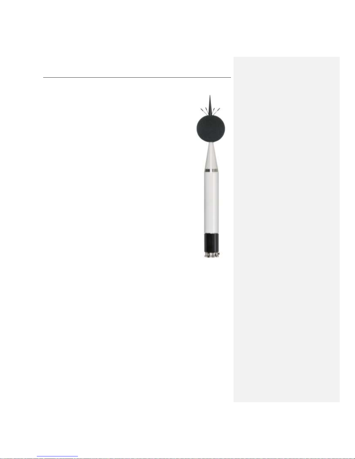
The SV 200 is a unique Noise Monitoring Terminal (NMT) which includes in single
portable housing: outdoor microphone, sound level meter and 1/1 & 1/3 octave
analyzer, advanced logger integrating controller and communication systems.
Using the most recent and State of the Art technological achievements, the
design of high integration outdoor system became available. In practice this
means that system can be easily transported and installed by one person in field.
The instrument is an ideal choice for unattended permanent and short period
environmental noise measurements together with weather conditions monitoring.
Instrument can be used for community and airport noise monitoring in the same
time.
The architecture of the system allow easy communication, data download and
configuration of the system using PC or any mobile device which has network
(internet) access to SV 200 and web browser.
The SV 200 meets Class 1 requirements of IEC 61672:2013 standard. NMT
provides broad band results with all required weighting filters, 1/1 octave & 1/3
octave spectra with complete statistical analysis.
Instrument can be easily calibrated in field using acoustic calibrator. Built-in
electrostatic actuator can be activated remotely or periodically in automated
mode for self-testing.
The SV 200 enables great logging capability which includes time history of broad
band results and spectra with two selectable logging steps down to 2 milliseconds
like also audio records on trigger. Data are stored on microSD card and can be
transferred over the internet on demand or in automatic mode to FTP server or
any PC.
SvanPC++ and SvanPC++_RC software provides advanced modes of
communication, files download, data visualization and measurement results
exporting. SvanPC++_EM environmental monitoring software is dedicated for
measurement data management, advanced data processing, analysis,
visualization and reporting.
Thanks to robust casing, protection against overheating & humidity condensation,
built-in rechargeable battery, this instrument is excellent for permanent
installation in all environmental conditions.
1.1 Sound Level Meter & Analyser features
• noise measurements: SPL, Leq, SEL, L
DEN
, L
tm3
, L
tm5
, L
peak
, L
max
, L
min
• statistics: Ln (L1 – L99), complete histogram in meter mode and 1/1 & 1/3 octave analysis
• Type 1 accuracy in the frequency range 3.5 Hz – 20 kHz and with 48 kHz sampling rate
• total linearity measurement range: 25 dBA LEQ ÷ 133 dB PEAK
• dynamic range: 115 dB
• parallel Impulse, Fast and Slow detectors for the measurement with A, C or Z weighting filters
• software selectable community and airport direction characteristics
• digital True RMS detector with peak detection, resolution 0.1 dB
• 1/1 octave real-time analysis meeting Class 1 requirements of IEC 61260, frequencies from
3.15 Hz to 20 kHz
• 1/3 octave real-time analysis meeting Class 1 requirements of IEC 61260, frequencies from
3.15 Hz to 20 kHz
• audio events recording: time domain records to wav file format on demand with selectable
sampling frequency and recording period
Page 7

SV 200 USER MANUAL 7
1.2 General features of SV 200
• Noise monitoring terminal fitted in one portable instrument dedicated for unattended permanent
and short period noise monitoring
• Noise measurements meeting IEC 61672-1, type 1 standard
• 1/1 & 1/3 octave real-time analysis
• Audio events recording
• Statistical analysis with up to 10 percentile values
• Community and airport direction characteristics, software selectable
• Remote, automated calibration check
• High efficiency windscreen
• Designed for outdoor use in all weather conditions
• Communication over 3G or Wi-Fi modems
• Weather monitoring module
• Easy remote access over PC or Smartphone by means of any Web browser
• Precise time synchronization and GPS position of the measurements
• Up to 45 hours autonomy (internal battery operating time with modem switched off)
• Advanced software for data processing and reporting SvanPC++_EM
• Direct connection of solar panel or DC power supply
• Robust design
• Ingress Protection Rating IP 65
• Easy and fast installation in field
1.3 Accessories included
• Microtech Gefell MK 255, 50 mV/Pa, prepolarised ½” condenser microphone
• integrated, non-removable microphone preamplifier
• Li-Ion rechargeable battery (non-removable)
• water proof external DC power supply
• built-in acoustic actuator, triggered manually or in automated mode,
• 16 GB micro SD card (non-removable)
• 3G modem (included in version SV 200_3G)
• Wi-Fi module (included in version SV 200_WiFi)
• SC256 USB cable
• standard mounting kit
1.4 Optional accessories available
• solar panel
• user control unit (on cable)
• SV 205B meteo module
• SV 58 GPS module
• alarm lamp
• SvanPC++_EM Environmental monitoring module for SvanPC++ application (hardware key,
single license)
• side mounting kit
Page 8

SV 200 USER MANUAL 8
2 ASSEMBLING THE INSTRUMENT
2.1 Recommended order of assembly
After unpacking, check the completeness of the set according to section 2.2.
Notice: It is advised to read sections 2.3 to 2.8 of the User Manual carefully before the
assembly.
Recommended order of installation:
1. pre-assembling of the SV 200 (see 2.3),
2. pre-assembling of the meteorological beam (see 2.4),
3. power supply installation (see 2.5),
4. assembling of the meteorological beam on the mast (see 2.6),
5. assembling of and start-up of the SV 200 device (see 2.7),
6. arrangement of the cabling (see 2.8).
2.2 Delivered kit
The kit delivered to the client consists of the following elements:
1. the SV 200 instrument containing sub-assemblies unavailable to clients:
• integrated, non-removable microphone preamplifier
• built-in electrostatic actuator, triggered manually or in automated mode
• Li-Ion rechargeable battery
• 16 GB micro SD card
• 3G modem (included in version SV 200_3G)
• Wi-Fi module (included in version SV 200_WiFi)
Page 9

SV 200 USER MANUAL 9
2. removable elements of the SV 200:
• Microtech Gefell MK 255, 50 mV/Pa, prepolarised ½” condenser microphone
• top cone with anti-bird spikes
• extension sleeve
• microphone protective sleeve
• SA209 5” foam windscreen
• 3G antenna (for version 1)
• Wi-Fi antenna (for version 2)
3. DC power supply kit consisting of:
• weatherproof DC power unit of the type SA213
• set of 4 dowels Φ 10 mm (with screws) for mounting the power unit into a wall
• 2 band clips for mast mounting of the power supply
4. SC256 cable to communicate with SV 200 using USB interface
top cone with
anti-bird spikes
SA209 foam
windscreen
extending sleeve
microphone
protective sleeve
microphone
Page 10
SV 200 USER MANUAL 10
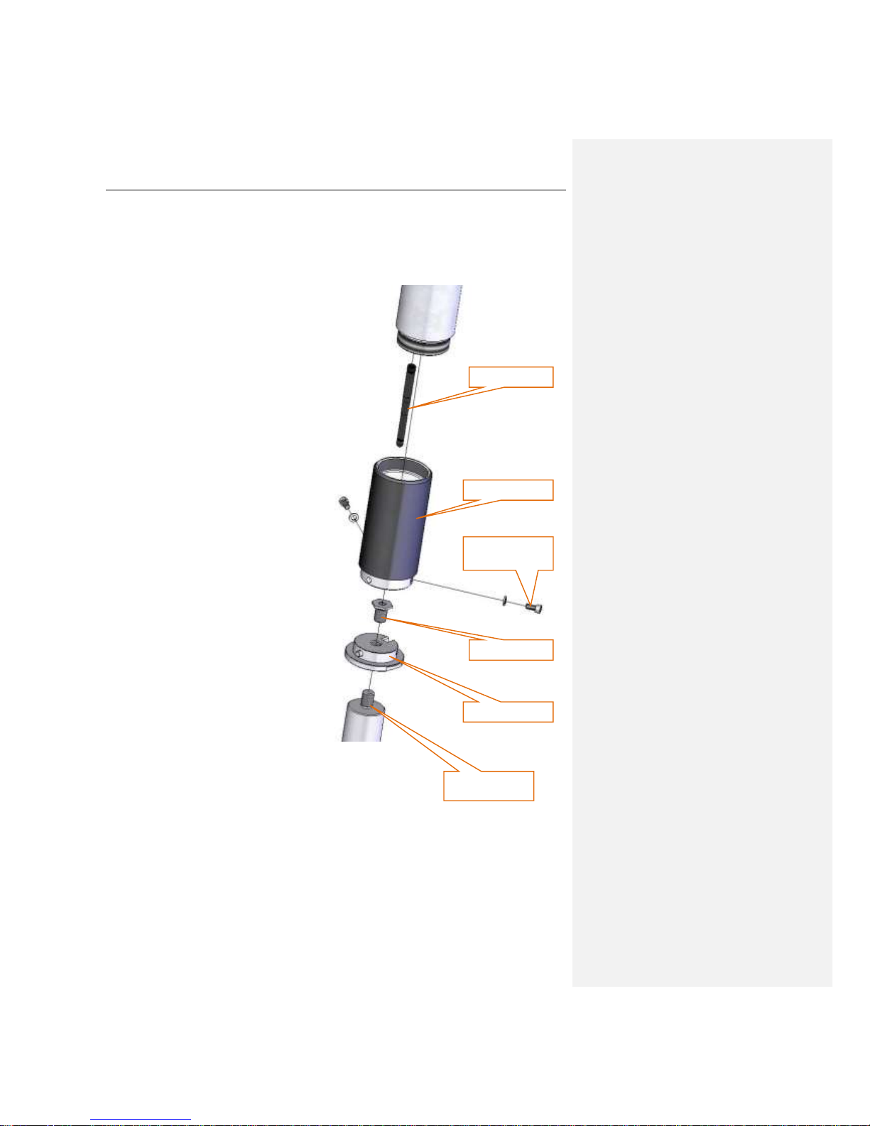
5. Standard mounting kit consisting of:
• mounting sleeve
• base of the sleeve
• two bolts M6x12 with washers
• M14/
3/8
” adapter
base of the sleeve
M14/
3/8
” adapter
two bolts M6x12
with washers
mounting sleeve
wireless antenna
Example of pole
mounting
Page 11

SV 200 USER MANUAL 11
6. set of the elements of the meteorological beam (option), consisting of:
• SV205B hygro-baro-thermometer module (optionally with rain detector mounted on it)
• dedicated SC258 cable to connect the SV205B module to the SV 200
• ultrasonic wind-meter adapted to be connected to the SV205B device
• meteorological beam (fastening clamp inner diameter 45 mm)
• 4 knobs with nuts M8
• 2 knobs with bolts M8x25
• three cable holders 28/40 mm
• three bolts M5x10
• two tuning bolts
wind-meter
3 bolts M5x10
SV205B hygro-baro-thermometer
rain detector (optional)
2 knobs with nuts M8
beam fastening
clamp
2 knobs with nuts M8
2 knobs with
bolts M8x25
3 cable holders
meteorological beam
tuning bolts
Page 12
SV 200 USER MANUAL 12
7. set of tools, consisting of:
• special ring spanner 22mm
• special open spanner 65 mm
• Allen key 3mm
• Allen key 5mm
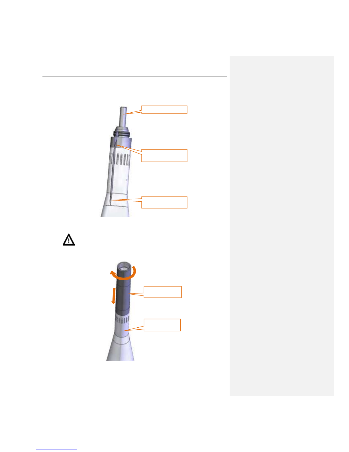
2.3 Pre-assembling of the SV 200
Install the microphone and the foam windscreen in the following order:
1. Check, if the SV 200 is switched off – LED indicators on the bottom panel of the instrument are
not lighting. If the device is on, turn it off (see Chapter 3.1)
2. Place the SV200 upright (outer cone facing up) on a hard horizontal flat surface. The device
should not rock or overturn after this step.
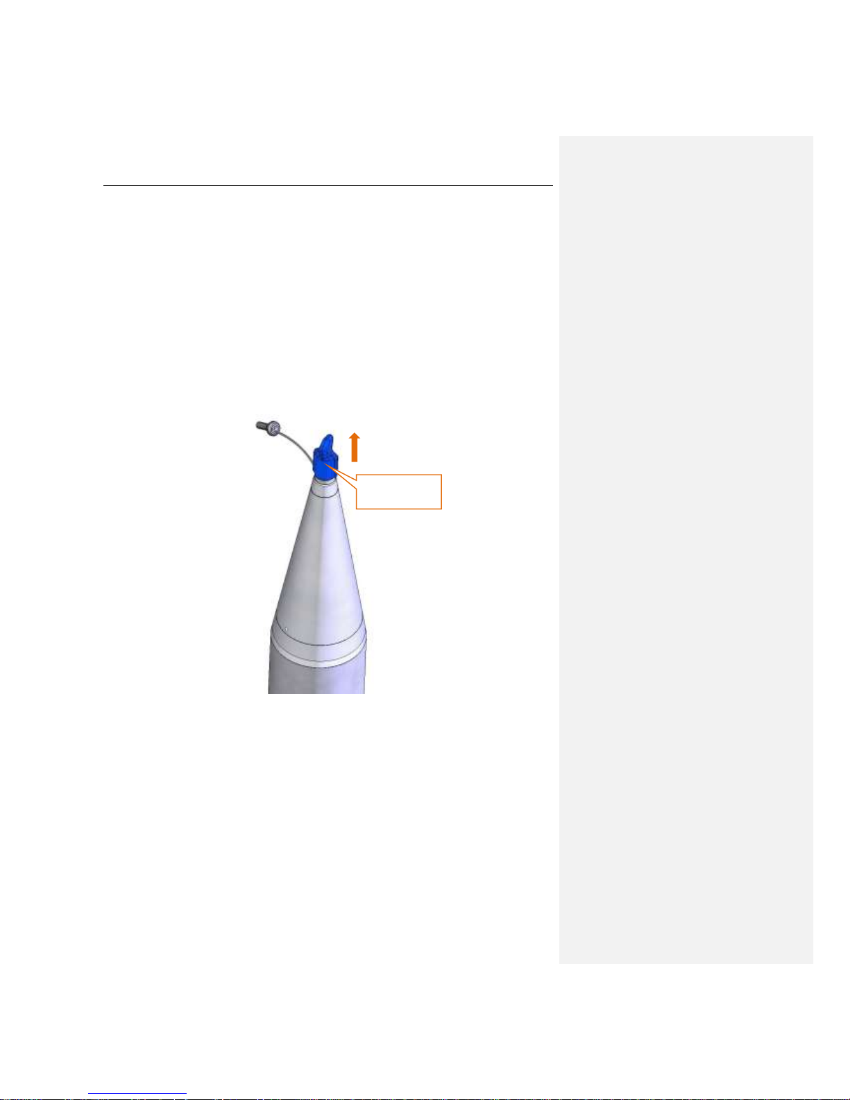
3. Take off the protective cap from the microphone socket.
take off the blue
protective cap
Page 13
SV 200 USER MANUAL 13
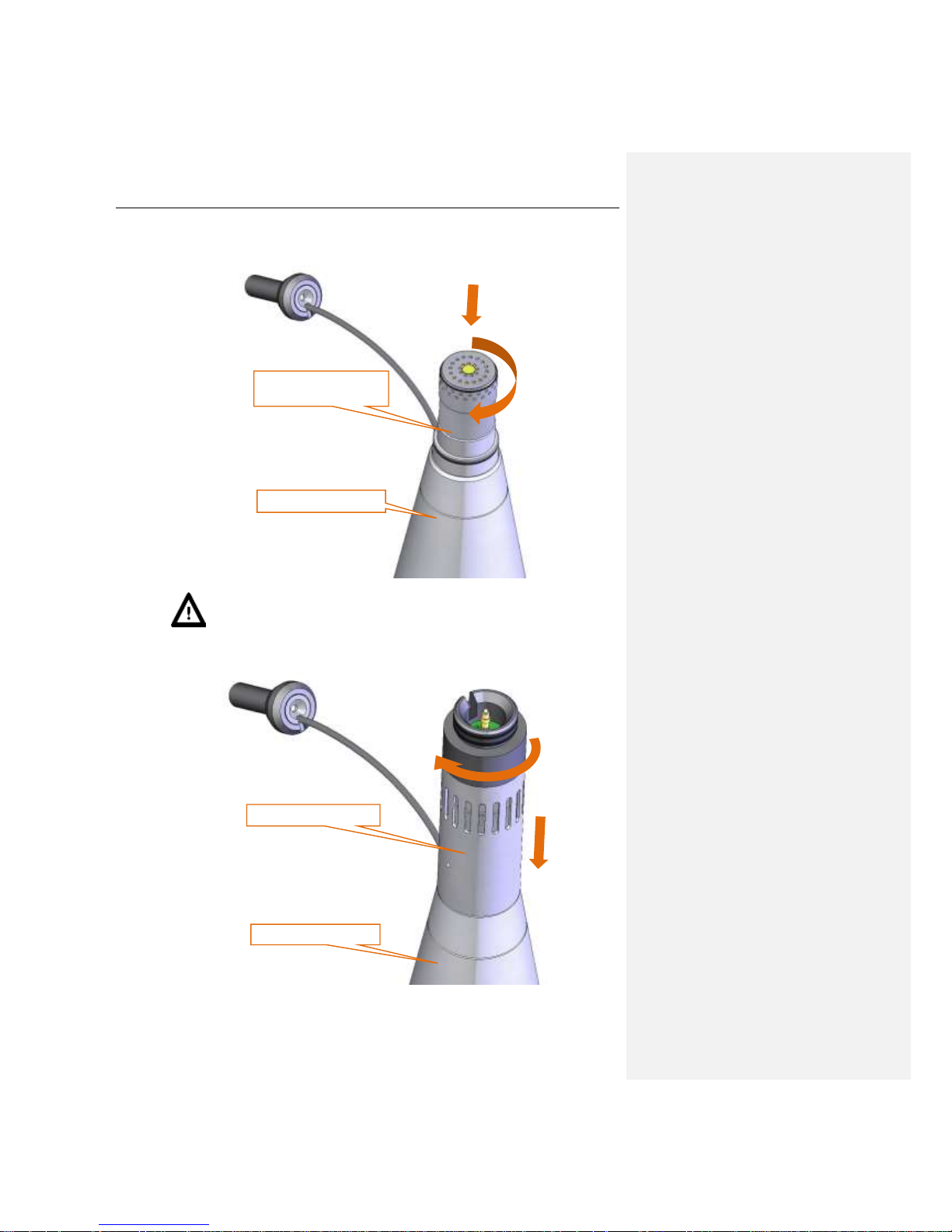
4. Holding outer cone in one hand, use the other hand to screw the microphone on the matching
thread extending from the outer cone (rotating the microphone clockwise)
Notice: It is advised to calibrate the SV 200 at this point. For more information see
Chapter 3.7.
5. Hold the outer cone with one hand, use the other hand to screw on the sleeve rotating it
clockwise.
hold firmly with one hand
screw the microphone on
the microphone socket
2
hold firmly with one hand
screw the sleeve on
1
2
Page 14
SV 200 USER MANUAL 14
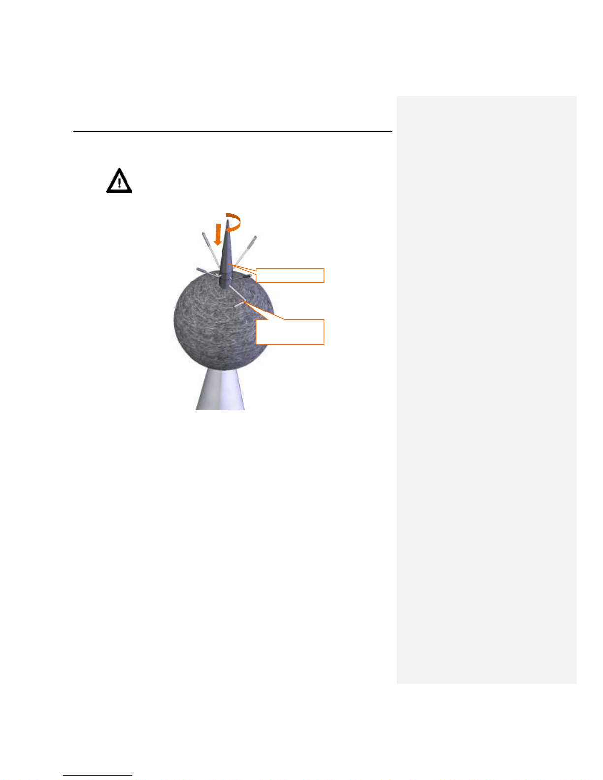
6. Align moving ring with the slot of the microphone protective sleeve so that the cable is not bent
in any direction. Gently place the actuator located at the end of the cable in the dedicated socket.
Put the actuator's cable into the slot of the sleeve.
7. Hold the microphone protective sleeve and the top cone with one hand, use the other hand to
screw on the extension sleeve, rotating it clockwise
Notice: It is important to keep the microphone protective sleeve still, to protect
actuator’s cable from damage.
insert into the socket
place the actuator cable
in the slot of the sleeve
align with the slot of the
sleeve
hold firmly with
one hand
screw the
1
2
Page 15

SV 200 USER MANUAL 15
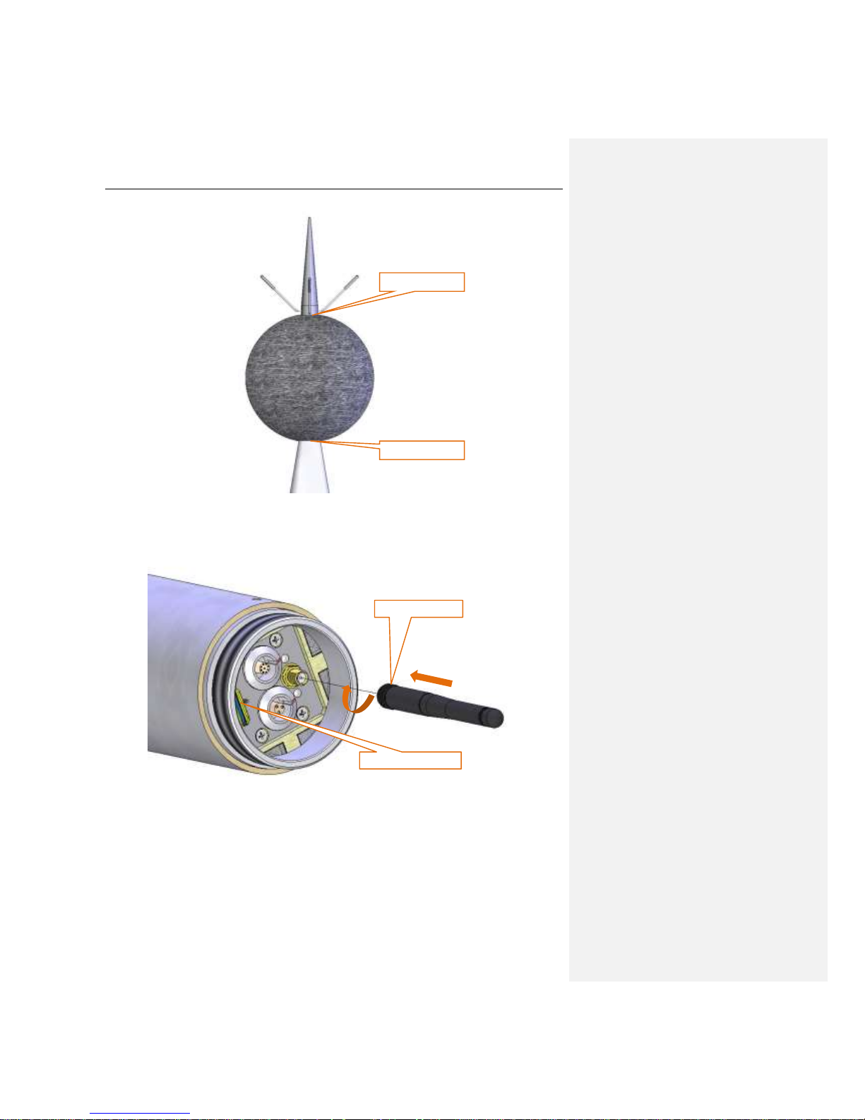
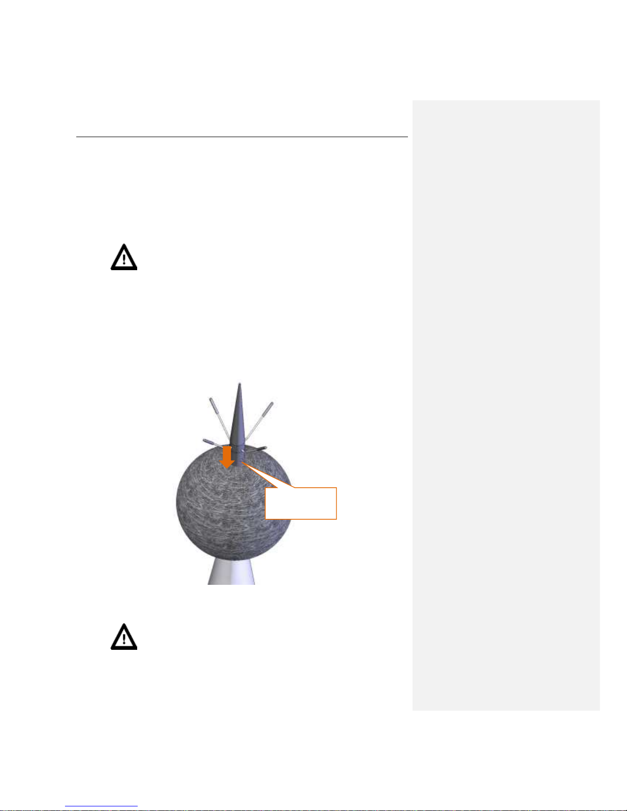
8. Slide the foam windscreen onto the extension sleeve and push the foam until you see the lateral
hole.
9. Insert the 3 mm Allen key into the hole.
push the foam windscreen
until you see the lateral hole
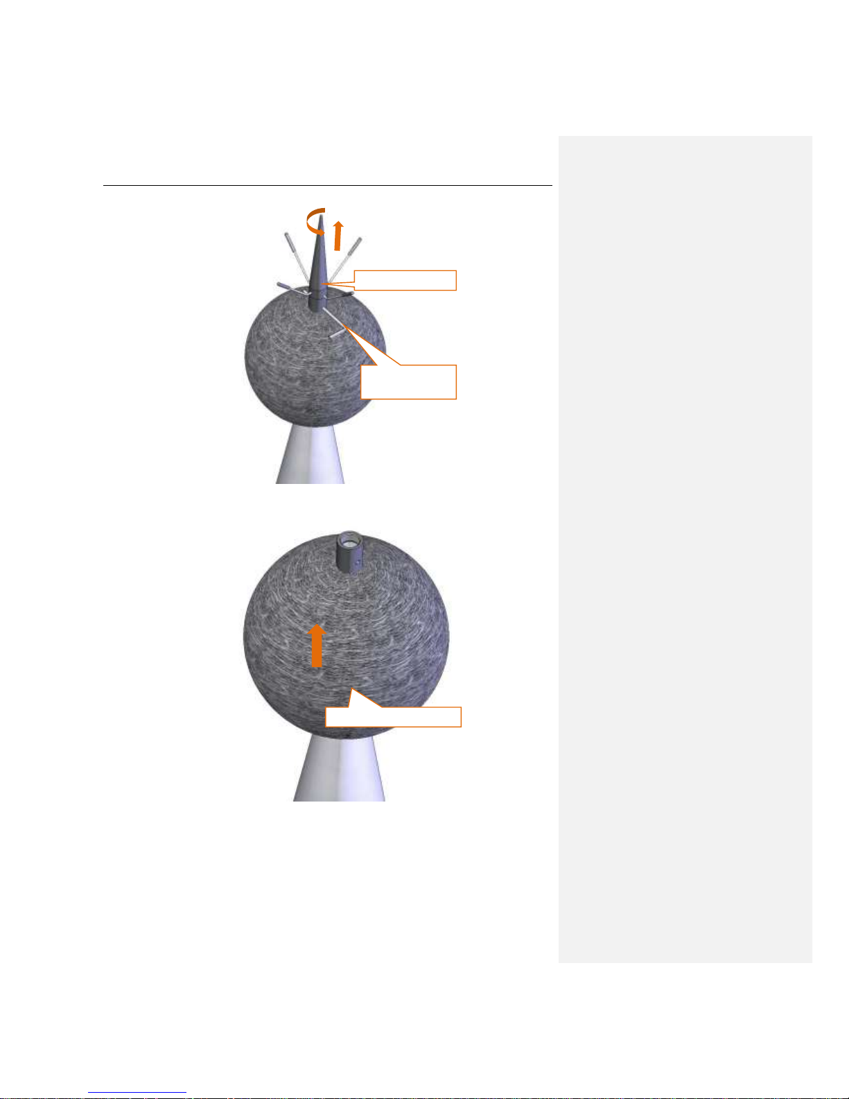
Page 16
SV 200 USER MANUAL 16
10. Holding the Allen key and the extension sleeve in one hand to keep them still, use the other
hand to screw on the top cone with the anti-bird spikes, rotating it clockwise.
Notice: It is important to keep the extension sleeve still, to protect actuator cable
from damage.
11. Take the Allen key out from the extension sleeve.
12. Move the foam windscreen to the place right under the spikes of the anti-bird device, make sure
it covers the microphone protective sleeve.
hold the Allen key
firmly in one hand
screw the top cone
Page 17
SV 200 USER MANUAL 17
13. Put the device horizontally to gain an easy access to the control panel.
14. Screw the wireless antenna.
In version 1 of the device, insert the SIM card into the SIM card socket (according to Chapter 3.2).
The device prepared in this way is ready for the electronic configuration (according to Chapter 3).
2.4 Pre-assembling of the meteorological beam (optional)
The meteorological beam may be pre-assembled during the installing preparations. The recommended
sequence of operations:
cover the sleeve
cover the hole
hold and screw on
insert the SIM card
Page 18
SV 200 USER MANUAL 18
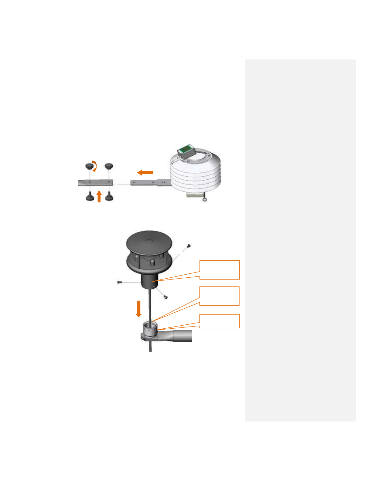
1. Unscrew two sets of knobs (each containing of a nut and a screw) from the flattened end of the
beam.
2. Put the beam on a flat surface so that the mounting socket of the wind-meter on the other side
of the beam faces up
3. Put the SV205B device with the label facing down.
4. Slide the flat band extending from the SV205B into the slot at the flattened end of the beam
5. Screw the SV205B unit to the beam using the knobs (see point 1), place the knobs with the
nuts on the top of the beam.
6. Unscrew three M5 screws from the fastening socket of the wind-meter using an Allen key 3 mm.
7. Thread the cable of the wind-meter through fastening socket on the beam.
8. Place the wind-meter on the fastening socket.
9. Screw the wind-meter to the socket with the three screws unscrewed before (see point 6).
10. Put the cable connected to the wind-meter along the meteorological beam at the side opposite
to the fastening clamp
11. Plug the cable connector into the socket in the cable box in the bottom part of the SV205B unit
(the socked signed „Wind Speed Meter” is protected with a cap, which must be removed)
1
2
3
fastening socket of
the wind-meter
thread the cable
through the
fastening socket
place the wind-
meter on the
fastening socket
Page 19
SV 200 USER MANUAL 19
12. Push the cable into the cable holders located on the meteorological beam
13. Plug the SC258 cable connector into the socket in the cable box on the bottom of the SV205B
unit (the socket signed „External Interface” is protected with a cap, which must be removed).
2.5 Power supply installation
The power supply may be installed in the following two ways:
1. On a wall, for example, using 4 anchors.
2. On a mast, using 2 band clips.
The outdoor installation requires the power supply to be installed vertically, with the protective plate
facing up. The power supply must be installed on below the SV 200 device. The distance should be as
great as possible.
Notice: Choosing the assembling place one should take into account that the cable
connecting the power supply to the device is 2,5 meters long and must not be extended.
2.6 Assembling of the meteorological beam (optional) on the mast
The meteorological beam should be installed on the mast, at least 2 m above the ground. The distance
from the beam to the SV 200 device should be as great as possible, but it is limited to the length of the
SC258 cable. There must not be any cables or wires between the clamping ring of the meteorological
beam and the mast.
After fixing the fastening place:
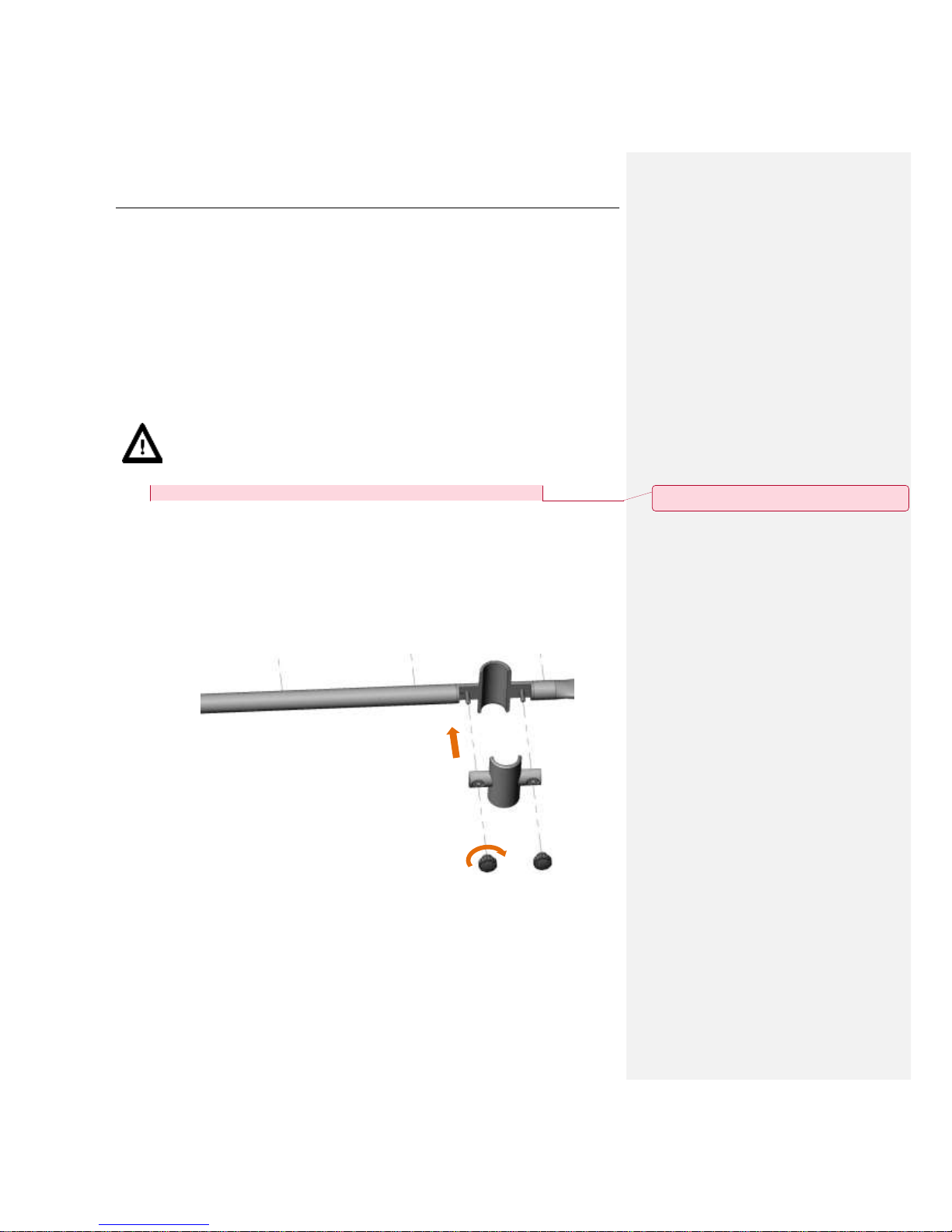
1. Unscrew two knobs which hold the beam fastening clamp of the meteorological beam.
2. Place the beam at the fixed place.
3. Install the beam to the mast using beam fastening clamp and two knobs.
Z komentarzem [J1]: Kilka miesięcy temu WB zlecił WK
oprcowanie nowej belki co się z tym wydarzyło
Page 20
SV 200 USER MANUAL 20
4. To align the wind-meter loosen two tuning bolts with the Allen key 1,5 mm and rotate the
wind-meter until the red north pointer indicates the north.
Notice: You can determine the north direction using either mobile app or real-life
compass.
5. Fasten the tuning bolts again.
6. Alternatively, loosen meteo beam fastening clamp and rotate the beam until the triangleshaped mark indicates north. Remember to tighten the knobs afterwards!
2.7 Mounting the SV 200
Coaxial mounting of the device on the mast Φ 45 mm ended with a bolt M14 is recommended.
Notice: The M14/
3/8
” adapter is intended for presentation mounting on photographic and
light tripods. It should not be used for unattended environmental monitoring.
Mounting on M14 thread
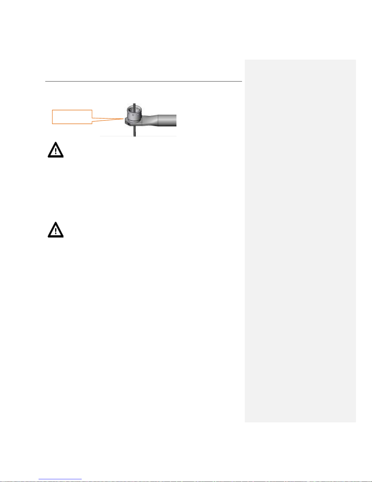
1. Unscrew two screws attaching the cup to the bottom of the cup with the Allen key 5mm.
2. Push the pin in the third hole in the bottom using a longer arm of the Allen key and take the
bottom off the cup.
3. Unscrew the M14/
3/8
” adapter from the bottom of the mounting sleeve using the special
spanners 22 and 65 mm.
loosen to align
properly
Page 21

SV 200 USER MANUAL 21
4. Screw the base of the mounting sleeve on the M14 thread of the mast (with wider side facing
down).
5. Tighten the bottom of the mounting sleeve up with the special open spanner 65 mm.
6. Make sure the SV 200 is switched off and has a wireless antenna installed.
7. Hold the mounting sleeve with one hand (with the chamfered edge of the cup facing up).
8. Thread the SC258 cable (connected to the meteorological station) and the SA213 power supply
cable through the cup from the bottom to the top.
9. Plug the power supply cable connector in to the DC IN socket on the control panel.
10. Plug the SC258 cable connector in to the Ext. I/O socket on the panel of the SV 200.
11. Press the <Power> button on the control panel to switch the device on.
12. Screw the mounting sleeve on the thread of the SV 200.
13. Push the dowel protruding from the bottom of the cup with Allen key 5 mm.
slot for cables
screw on the base
Page 22
SV 200 USER MANUAL 22
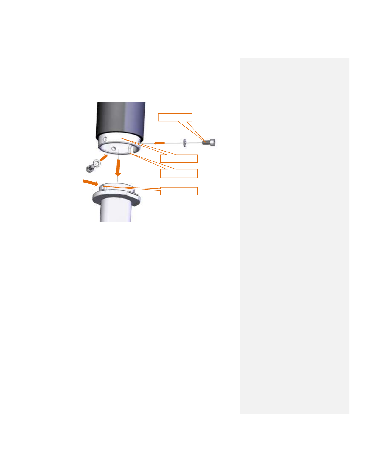
14. Put the mounting sleeve on the bottom of the cup so that the cable slot in the bottom of the cup
covers the cable slot in the cup.
15. When the dowel is in the side hole of the cup, screw both threads fastening the cup to the
bottom of the cup using the Allen key 5 mm.
Mount in g on 3/8” thr ea d
1. Unscrew two screws attaching the cup to the bottom of the cup with the Allen key 5mm.
2. Push the pin into the third hole in the bottom using a longer arm of the Allen key and take the
bottom off the cup.
3. Screw the bottom of the cup on the 3/8” thread (with wider side facing down).
4. Tighten the bottom of the cup up with the special ring spanner 22 mm.
5. Then follow steps 6 to 15 from Mounting on M14 thread (above).
1
press the pin
2
3
3
slide the sleeve
slot for cables
screw on
Page 23
SV 200 USER MANUAL 23
2.8 Finishing
Attach the cables to the mast and the meteorological beam. Use some band clips at intervals not greater
than 50 cm (20”) on the mast and the cable holders delivered with the kit on the meteorological beam.
Lay the cables so that they are loose at the ends. The loose cable should hang a bit lower than the
connector to avoid accumulation of rainwater.
2.9 Important information
The SA209 foam protects microphone from wind and rain.
Notice: If SV 200 is used continuously for a long period of time it is recommended
to replace SA209 foam at least once a year.
During continuous usage the SA209 foam is exposed to different weather conditions with possibility of
causing mechanical damage to the foam’s structure. Therefore it is recommended, at least once a
quarter (3 months), to check the condition of the foam by examining the surface for cracks by squeezing
the foam. If cracks or holes are observed, the SA209 foam must be replaced.
SA209 foam must be replaced whenever squeezing it causes severing of small pieces of its surface.
2.10 Preparing for calibration
If the SV 200 instrument is assembled and needs calibration, do what follows:
1. Push the foam windscreen until you see the lateral hole.
2. Insert the 3 mm Allen key into the hole.
3. Holding the Allen key and the extension sleeve in one hand to keep them still, use the other
hand to unscrew the top cone with the anti-bird spikes, rotating it counter-clockwise.
Notice: It is important to keep the extension sleeve still, to protect actuator cable
from damage.
push the foam
windscreen until you
see the lateral hole
Page 24
SV 200 USER MANUAL 24
4. Take the Allen key out from the extension sleeve.
5. Take the foam windscreen off the extension sleeve.
hold the Allen key
firmly in one hand
unscrew the top cone
take the foam windscreen off
Page 25
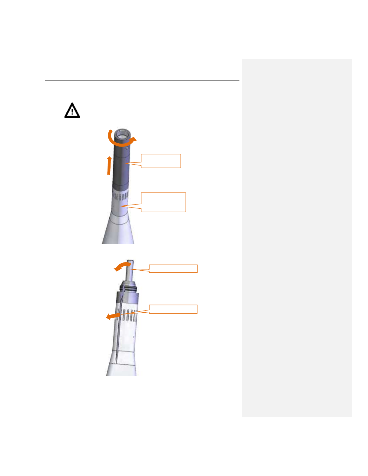
SV 200 USER MANUAL 25
6. Hold the microphone protective sleeve and the outer cone with one hand, use the other hand to
unscrew the extension sleeve, rotating it counter-clockwise.
Notice: It is important to keep the microphone protective sleeve still, to protect
actuator cable from damage.
7. Gently remove the actuator form the socket. Let the cable hang loose.
hold the microphone
protective sleeve
firmly with one hand
unscrew the
extension sleeve
1
2
remove from the socket
let the cable hang loose
Page 26
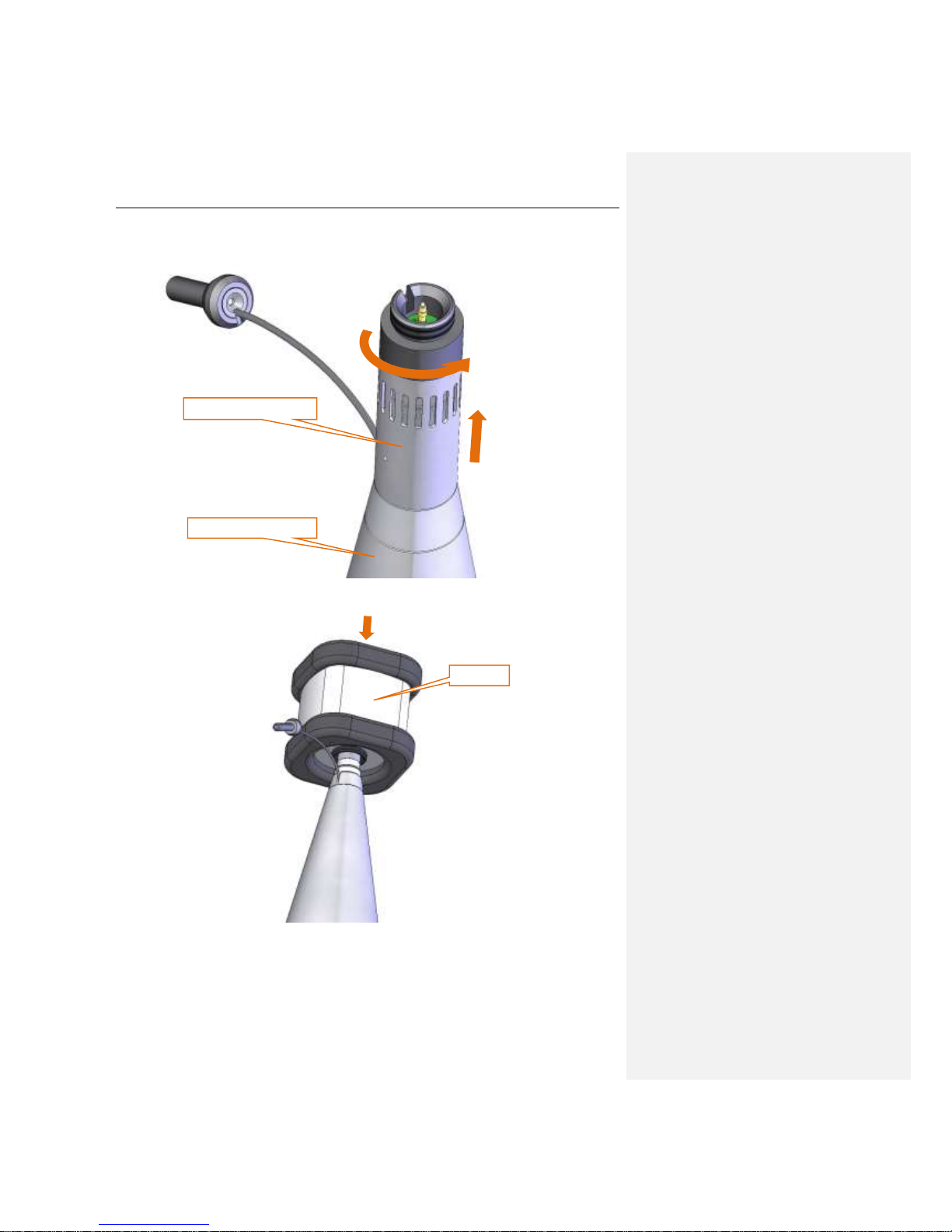
SV 200 USER MANUAL 26
8. Take the outer cone with one hand, use the other hand to unscrew the microphone protective
sleeve rotating it counter-clockwise.
9. Put the calibrator on the microphone
10. Calibrate according to Chapter 3.7.
11. Take the calibrator off after the calibration.
12. Then follow steps 6 to 12 from Chapter 2.3.
hold firmly with one hand
unscrew the sleeve
1
2
calibrator
Page 27

SV 200 USER MANUAL 27
2.11 Replacement of the foam windscreen
1. Take the windscreen off according to steps 1 to 5 of Chapter 2.9.
2. Install new windscreen according to steps 8 to 12 of Chapter 2.3.
Page 28
SV 200 USER MANUAL 28
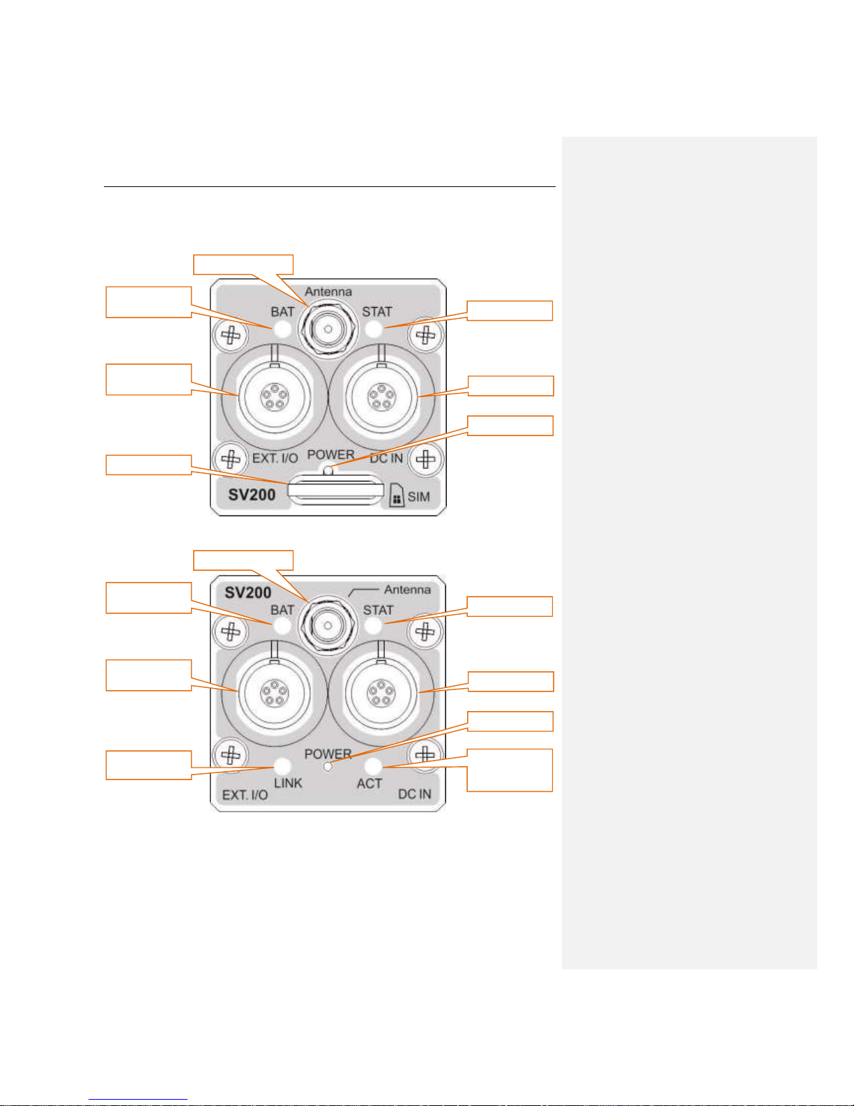
3 MANUAL CONTROL OF THE INSTRUMENT
3G modem version
LAN/WiFi version
battery
indicator
Antenna socket
external
interface socket
DC IN socket
POWER button
SIM card slot
status indicator
battery
indicator
Antenna socket
external
interface socket
DC IN socket
POWER button
cable link
status indicator
LAN/WiFi
activity
indicator
Page 29
SV 200 USER MANUAL 29
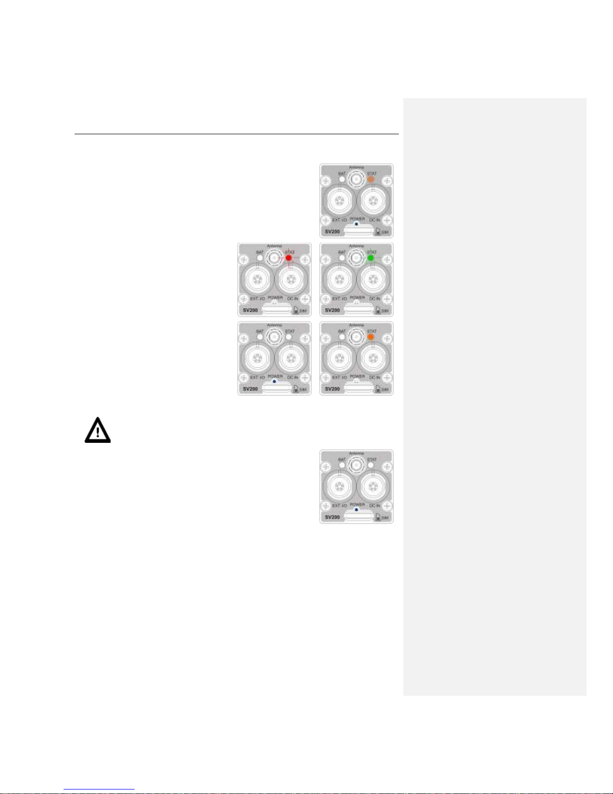
3.1 LED indicators and Power button
Switching the instrument on
The <Power> push-button is the only button on the control panel of the
instrument. It is used for switching the instrument on and off and also
starting/stopping the measurement manually.
When the SV 200 is turned off a short press of the <Power> button turns
it on. During the start-up process the STAT indicator turns orange.
Starting measurement
When the station is switched on the STAT LED
flashes in red (when the measurement is
stopped) or in green (when the measurement is
running). The short press of the <Power>
button, enables the user to start/stop the
measurement.
Switching the instrument off
To turn the SV 200 off press and hold the
<Power> button until the STAT indicator turns
orange. After a few seconds the instrument is
switched off.
Notice: Pressing the <Power> button for longer than 3 seconds during start-up, boots
the SV 200 in BOOTSTRAP mode, used for firmware update (Chapter 3.5). When the
instrument has entered the BOOTSTRAP mode, the STAT LED is solid green.
Resetting the instrument
To hardware reset the SV 200 press and hold the <Power> button for at
least 10 seconds.
Page 30
SV 200 USER MANUAL 30
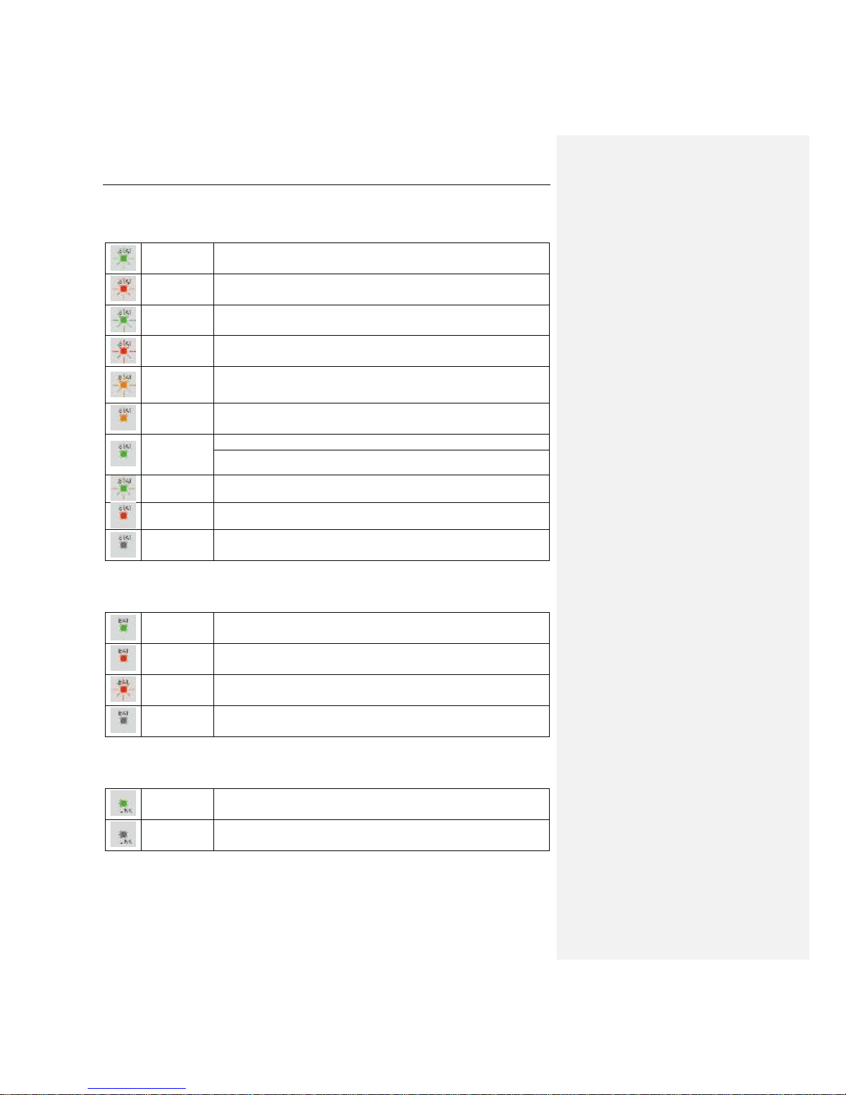
STAT indicator
Meaning of the STAT LED states is described in the below table.
green flashing
Measurement in progress
red flashing
Measurement stopped
green double
flashing
Measurement in progress, 3G connection established (3G version only)
red double
flashing
Measurement stopped, 3G connection established (3G version only)
orange
double
flashing
Measurement in progress, data transmission in progress (3G version only)
orange solid
Turning the instrument on/off
green solid
Bootstrap mode
Calibrator installed and Auto Calibration feature on: Auto Calibration procedure
completed
green and red
flashing
Calibrator installed and Auto Calibration feature on: Auto Calibration in progress
red solid
Calibrator installed and Auto Calibration feature on: Auto Calibration procedure failed
no light
Instrument turned off
BAT indicator
Meaning of the BAT LED states is described in the below table.
green solid
Battery charged
red solid
Charging battery
red flashing
Battery pack damaged or disconnected. Contact local SVANTEK
dealership
no light
When instrument connected to the power supply – battery deeply
discharged. Charging battery with low current
LINK indicator (LAN/WiFi version only)
Meaning of the LINK LED states is described in the below table.
green solid
LAN cable connected properly
no light
LAN cable disconnected
Page 31

SV 200 USER MANUAL 31
ACT indicator (LAN/WiFi version only)
Meaning of the ACT LED states is described in the below table.
green solid
LAN/WiFi connection estabilished
green rapidly
flashing
LAN/WiFi activity
3.2 SIM card slot (3G version only)
Notice: The SIM card slot is present only in devices equipped with 3G modem.
The SIM card should be inserted into the slot to ensure 3G connection. Push the card in until a click can
be heard. Make sure the contact area of the card is facing down.
To remove SIM card from the slot push it until the click is heard and pull the card out.
Further information on configuration of the 3G connection can be found in Chapter 6.
3.3 DC IN socket
The DC IN socket is used to connect external power source, i.e. provided power supply, optional solar
panel or external battery pack.
The SV 200 can be powered using one of the following power sources:
• Li-Ion batteries, fitted internally. Operating using the internal Li-Ion batteries depends on the
power consumption:
➢ up to 45 hours – modem off,
➢ up to 30 hours – 3G modem on,
➢ up to 20 hours – WiFi modem on.
• Provided AC power supply. Input 110-240 VAC, output +24 VDC 2.5A, IP66 housing.
• Optional solar panel. MPPT voltage 17 V-20 V, connected directly to the SV200, without using
power conditioner.
• External DC source. Voltage range 10.5 V – 24 V, e.g. 12 V or 24 V battery.
The internal battery is charged in a fully automatic cycle, when the instrument is connected to any
external power source. The SV200 charges itself irrespectively of it being turned on or off. The weather
conditions (i.e. temperature) are taken into account while charging to prevent any damage of the battery
caused by charging in too high or too low temperature.
Notice: The SV 200 is equipped with the mechanism which protects the internal Li-Ion
batteries from damage caused by critical discharge. When the battery is running flat, the
instrument is automatically switched off.
Page 32

SV 200 USER MANUAL 32
3.4 External Communication Interface socket
The EXT. I/O socket enables the user to connect the instrument to one of the following devices:
• PC (via USB)
• LAN
• SV 200CU user control unit
• SV 205B meteo module
• SV 58 GPS module
• Other RS232 device
• alarm lamp
• external trigger
3.5 Antenna socket
The Antenna socket is used to connect 3G or Wi-Fi antenna (depending on the version of the
instrument). Antenna is equipped with the matching plug with a locking screw, securing it to the body of
the instrument.
After plugging the antenna into the socket, the screw should be tightened to light resistance only. Do
not over tighten this connector.
3.6 Calibration
The instrument is factory calibrated with the supplied microphone for the standard environmental
conditions. Because the microphone sensitivity is a function of the temperature, ambient pressure and
humidity, when the absolute sound pressure level value is important, the absolute calibration of the
measurement channel should be performed.
Preparing for calibration
1. In order to access the microphone it is necessary to disassemble following parts of the SV 200
according to Chapter 2.10:
• con nozzle,
• SA 209 foam windscreen,
• extension sleeve,
• microphone protective sleeve,
2. After disassembling attach the acoustic calibrator, SV30A (or equivalent 114 dB / 1000 Hz)
carefully over the microphone of the instrument.
calibrator
Page 33

SV 200 USER MANUAL 33
Notice: It is also possible to use an electro-mechanical pistonphone, which generates the
signal (ca 124 dB) or different type of acoustic calibrator dedicated for ½” microphones.
In any case, before starting the calibration measurement, the user has to set the level of
the signal generated by the given calibrator, which is stated in the calibration certificate
of the unit.
3. Switch on the calibrator and wait ca 30 seconds for the tone to stabilise before starting the
calibration measurement.
Using Automatic Calibration feature of SV200
Notice: Automatic Calibration feature is switched off by default. To switch this feature on
see Chapter 6.13.
Automatic calibration feature was implemented to make calibration as easy as possible and to allow
technical personnel to perform a calibration of the SV200 with minimum knowledge and without any
additional devices like PC or SV200CU.
1. Switching the calibrator on begins the Automatic Calibration procedure.
2. Wait for the calibration to finish while STAT LED is flashing alternately red and green.
3. If Automatic Calibration is successful the STAT LED turns green. If otherwise the STAT
becomes solid red.
4. After detaching the calibrator from the SV200 the unit returns to its previous state.
Detailed description of the Automatic Calibration feature
The feature is based on 1 second integrated RMS(C) values which are calculated independently to
logger and summary results. These results are always available even if measurements are stopped,
which allows for the procedure to start any time.
The sound pressure level generated by the calibrator should be equal to previously configured level (see
Chapter 6.13) and stable within ±0,1dB margin
If previous conditions are met, measurements are stopped (if were running) and outdoor filter is turned
off. Automatic calibration is in progress, which is signalized by STAT LED alternate red and green
flashes. If level is stable (next three results are within ±0,1dB margin), calibration factor is calculated.
Automatic calibration success if calibration factor is within ±3dB.
To finish the automatic calibration procedure, just remove the calibrator. STAT LED of the SV200 returns
to its normal mode reflecting state of the SV200: start, stop, internet connection etc.
Page 34
SV 200 USER MANUAL 34
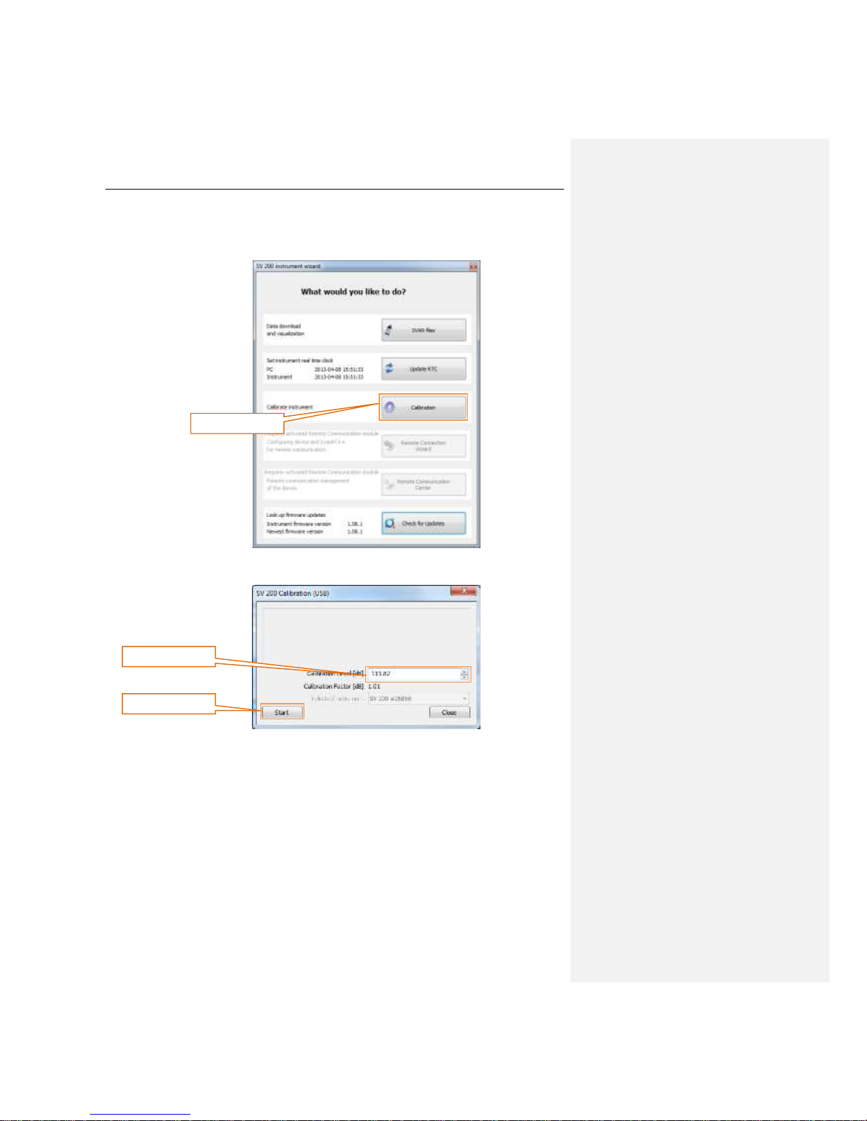
Using SvanPC++ with USB connection
1. Connect the SV 200 with PC using SC 256 cable and start SvanPC++.
2. When SV 200 instrument wizard appears on the screen, click Calibration.
3. Set desired calibration parameters in the SV 200 Calibration window.
Calibration button
Start button
Calibration level
Page 35

SV 200 USER MANUAL 35
4. Start the calibration measurement by pressing the Start. Performing the calibration (with Start
button) will result in calculating the Calibration Factor. Calibration measurement can be
terminated by pressing Terminate button.
Notice: During the calibration measurement, the level of external disturbances (acoustic
noise or vibrations) should not exceed a value of 20 dB below the level of signal generated
by the calibrator (94 dB when using a calibrator that generates a level of 114 dB).
5. Confirm obtained calibration factor by clicking Yes button.
6. Assemble the SV 200 according to Chapter 2.3 of the manual.
Using SV200CU User Control unit
See Chapter 9.6.3.
3.7 Electrostatic actuator
The Electrostatic actuator is used for remote calibration and system check of the instrument. It
generates a 94 dB (re. 20 μPa), 1 kHz tone.
The actuator can be turned on and off manually by the user with Web Interface or remotely using
suitable options in Automatic Files Download or Continuous Logger Download windows of SVAN
PC++ Remote Control.
Auto System Check feature enables the user to configure and schedule automatic checks of the
instrument. It can be set up using SvanPC++ (see Chapter 6.13) or in the Web Interface (see Chapter
7.3.4).
Notice: Actuator can be also controlled using #7,AC; remote function. For further
information see Appendix A.
Terminate button
Calibration factor
Page 36

SV 200 USER MANUAL 36
4 BASIC OPERATIONS
In order to configure the SV 200 the user has to assemble the instrument according to the instructions
in Chapter 2.3, connect the powers source and switch the power on by pressing the Power button.
4.1 PC Software installation and activation
To configure the SV 200 instrument for the first time the user needs to use PC running SVAN PC++
software. It allows you to easily control each function of the instrument and manage whole noise
monitoring station systems consisting of more than one SV 200 device.
1. Choose suitable PC. Make sure that it has active Internet connection if you wish to use SV 200
via the Internet. PC should be running Windows XP/Vista/7/8 operating system. Minimum
system requirements: 1GHz CPU, 1 GB RAM (2GB RAM for x64 system), 20 GB HDD,
1024x768 display.
2. Download and install SVAN PC++ software and Svantek USB Drivers from
http://svantek.com/lang-en/support/software.html website.
3. Prepare the activation key, that has been provided with the device.
4. On the Help menu click Enter Activation Keys… option and enter the key to activate Remote
Communication module.
5. Your SVAN PC++ software is ready to use with SV 200.
Notice: Remote Communication module is activated for each individual SVAN device.
Remember to enter activation key for any new device you wish to manage with RC
module.
4.2 Initial setup of the instrument
SV 200 can be easily configured with SVAN PC++ computer software. After connecting the instrument
to the computer running SVAN PC++ with SC 256 USB cable the SV 200 instrument wizard window
appears on the screen. It enables the user to:
• Manage the instruments’ file structure (SVAN files button)
• Set the instruments’ real time clock to be equal with computer clock (Update RTC button)
• Calibrate the instrument (Calibration button)
• Easily configure remote communication with the instrument (Remote Connection Wizard
button)
• Manage already configured devices (Remote Communication Center button)
• Look up for firmware updates (Check for Updates button)
Page 37

SV 200 USER MANUAL 37
4.2.1 Basic configuration of wireless connection
In order to access SV 200 remotely to download measurement files, manage configuration, receive
alarm emails etc. the instrument must be properly configured. SV 200 is equipped with either internal
3G modem or LAN/WiFi module. Before proceeding with configuration make sure, which version of the
instrument is going to be configured.
Notice: SVANTEK does not provide SIM card for the instrument. If you own SV 200 with
3G modem option it is necessary to purchase SIM card with data plan with deactivated
PIN code. For some features, like Web Interface, public IP address may be required. If
the instrument is intended for constant monitoring choose service provider that ensures
good reception at the measurement point.
Notice: SVANTEK does not provide SIM card for the instrument. If you own SV 200 with
3G modem option it is necessary to purchase SIM card with data plan. For some features,
like Web Interface, public IP address may be required. If the instrument is intended for
constant monitoring choose service provider that ensures good reception at the
measurement point.
Notice: for SIM cards with a static IP address it is not possible to use Remote
Connection Wizard feature described below. To set up wireless connection manually see
Chapter Błąd! Nie można odnaleźć źródła odwołania..
1. Connect the instrument to the PC configured according to Chapter 4.1 with the provided SC256
USB cable.
2. In SVAN PC++ SV200 instrument wizard window click Remote
Connection Wizard button. Remote Connection Wizard window
enables the user to create and manage connection systems
consisting of one or more SVATEK instruments capable of remote
connection (i.e. SV 200).
3. If there is no active connection system and the Add station button is inactive the user needs to
create one before configuration of a new monitoring station by clicking New connection system
button or load previously saved system from the *.svs file by clicking Load from file button.
4. To add new station to an existing connection system click Add station button.
Notice: For more details on wireless connections see Chapter 5.
New connection
system button
Add station button
Load from file
button
Page 38

SV 200 USER MANUAL 38
3G version
1. After clicking the Add station button the Select
system type… window will appear. Make sure the
SIM card is properly inserted into the SIM card slot
of the device. Click Internet button to continue
configuration.
2. Add new station window enables the user to configure all crucial parameters of 3G connection
in simple and user friendly way. The user can enter station name and description, to easily
identify the instrument after the wizard is finished. APN is mandatory field required to set up
the connection. APN value is specific for each mobile operator, who should deliver such
information.
3. DNS Server and Authorization mode should be left unchanged unless SIM card requires
otherwise. In such case suitable information should be delivered by the mobile service operator.
4. User is allowed to choose between two Registration modes: AS or DynDns. AS registration
mode is provided by SVANTEK and requires no additional information. To use this mode contact
your local SVANTEK distributor. DynDns mode requires the user to have active account on
www.dyn.com. In such case Hostname, Username and Password fields should be filled,
where Hostname is address assigned to the instrument and Username and Password are
dyn.com account login credentials.
APN field
Authorization mode
Registration mode
Page 39
SV 200 USER MANUAL 39
Notice: If the user wishes to use SV200’s web interface (Chapter 0), either DynDns
registration mode should be chosen or SIM card with static IP address should be used
for AS registration mode.
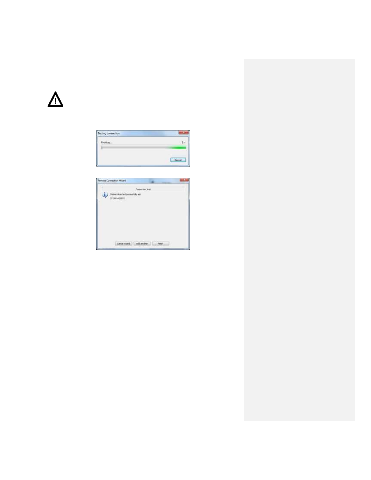
5. After entering all the required information SVAN PC++ will check connection settings. Wait until
process is finished. It may take a few minutes.
6. After finishing configuration the user can finish the wizard or add another instrument.
Page 40
SV 200 USER MANUAL 40
LAN/WiFi version
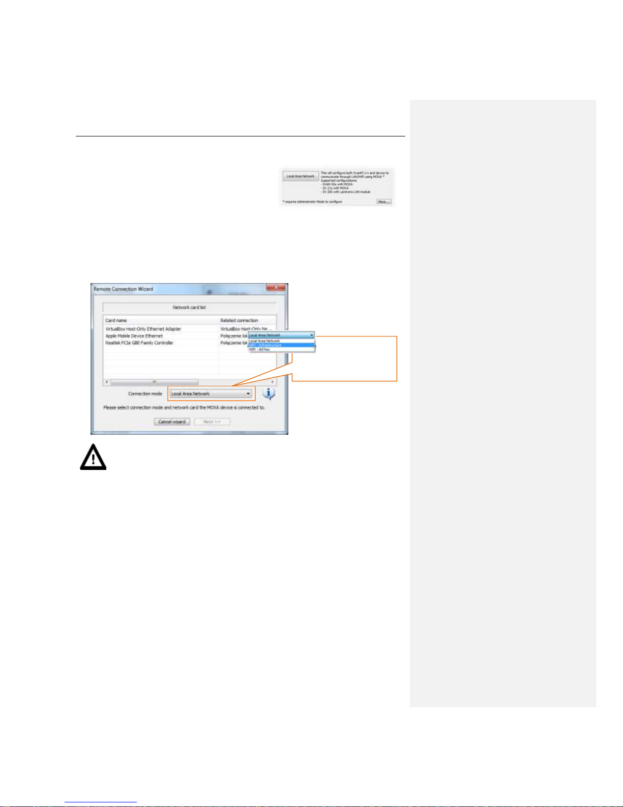
1. After clicking the Add station button the Select
system type… window will appear. Click Local
Area Network button to continue configuration.
2. Choose suitable Connection mode. If the user plans to connect the instrument via wired
connection Local Area Network connection mode should be chosen as well as the PC network
interface that will be used for connection. If the user intends to use wireless connection in an
existing WiFi network WiFi – Infrastructure option should be chosen. If the instrument is
supposed to create its’ own wireless network the user should chose WiFi – Ad hoc connection
mode.
Notice: Should WiFi – Ad hoc connection mode be chosen, PC wireless network
interface settings will be modified by the Wizard. If Windows Vista/7/8 is being used such
operation requires administrator rights.
Connection mode
Page 41
SV 200 USER MANUAL 41
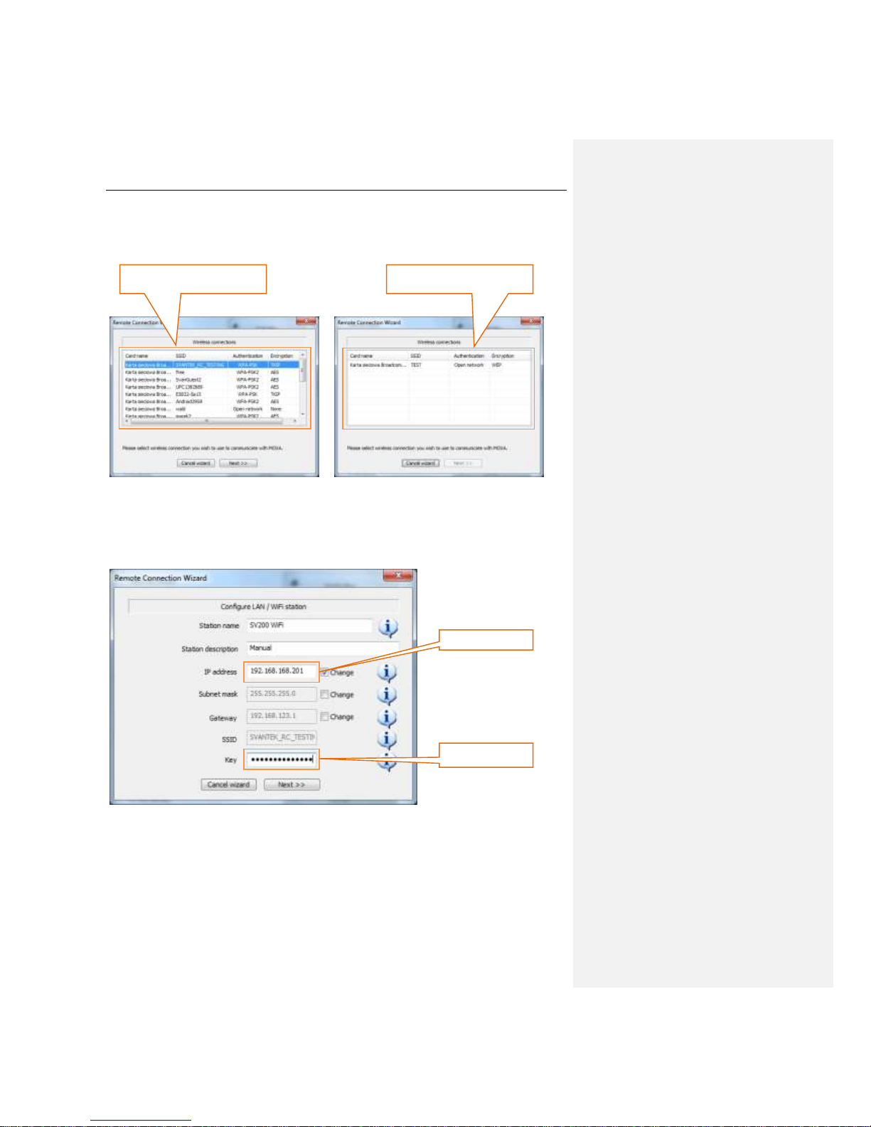
3. Depending on the connection mode the user needs to choose wireless network to connect to
(in case WiFi – Infrastructure mode was chosen previously), choose network interface to
reconfigure (in case WiFi – Ad hoc mode was chosen previously) or go straight to step 4.
4. Configure LAN / WiFi station window enables the user to configure all crucial parameters of
LAN/WiFi module in simple and user friendly way. The user can enter station name and
description, to easily identify the instrument after the wizard is finished. Network settings such
as IP Address, Subnet Mask and Gateway can be modified.
5. In case of wireless connection Network key should be entered.
Wireless network list
(WiFi – Infrastructure)
Wireless network interfaces
(WiFi – Ad hoc)
IP Address
Network Key
Page 42

SV 200 USER MANUAL 42
6. After entering all the required information SVAN PC++ will check connection settings. Ensure
that the PC is connected to the same network as the instrument for the connection test to
succeed. Wait until process is finished. It may take a few minutes.
7. After finishing configuration the user can finish the wizard or add another instrument.
Page 43

SV 200 USER MANUAL 43
4.2.2 Starting measurement
SV 200 is able to monitor and log noise by enabling up to three different parameter configuration
settings, also referred to as “ACOUSTIC PROFILE, each one with different filter (A, C and Z) and
detector (SLOW, FAST and IMPULSE) settings.
Notice: The SV 200 provides AutoStart feature. If the instrument is idle for 60 s the
measurement is automatically started.
Using POWER button
1. Make sure that the instrument is turned on.
2. Press <Power> push-button shortly.
3. Starting of the measurements will be signalized by green flashing STAT LED on the instrument’s
user panel.
Using SvanPC++
1. Make sure that the instrument is turned on.
2. Open Remote Communication Center.
3. Make sure appropriate Connection type is selected. If you wish to communicate with the
instrument via 3G, LAN or WiFi connection select Internet. If you wish to communicate with the
instrument via USB cable select USB.
4. Select the station in Station list box.
5. Check the state of the instrument by clicking Check instrument(s) status. When the instrument
status is known, Start measurement button becomes enabled.
6. Click Start measurement button.
Connection type box
Station list
Check instrument
status button
Start
measurement
button
Page 44

SV 200 USER MANUAL 44
Using Web Interface
1. Open to the instruments’ Web Interface by entering IP address or domain name into your web
browser address bar.
2. Once Web Interface is loaded navigate to Configuration tab.
3. In Configuration tab click Start measurements button.
4. Starting of the measurements will be signalized by green flashing LED icon in the top left corner
of the Web Interface site.
Using SV 200CU User Control unit
See Chapter 9.4. on swithing the control unit on and starting measurement.
Configuration tab
Start measurements
button
Page 45

SV 200 USER MANUAL 45
4.3 Changing the working directory
Working directory is a folder on the SD card in which all the measurement data is stored.
Changing the working directory can be conducted with SVAN PC++ software either locally via USB
cable or remotely using RC module with SVAN Files feature.
1. Make sure measurement is not in progress.
2. After opening SVAN Files navigate to the desired directory using the left pane. The left pane
displays contents of the instrument SD card or internal memory. Create new directory if
necessary.
3. Click Set as working folder button.
4. Working directory of the SV200 is now set. All the result files are going to be stored in the
selected folder.
SVAN Files button
SVAN Files button
Navigation pane
Create new folder
Go to parent directory
Go to working folder
Set as working folder button
Page 46

SV 200 USER MANUAL 46
4.4 Firmware upgrade
The firmware which controls the SV 200 is possible for the user to upgrade. There are three separate
programs loaded into the instrument’s memory:
1. User Program,
2. BOOTSTRAP,
3. HARDBOOT.
The User Program controls all of the instrument’s functions i.e. measurements, communication, web
server etc. SVANTEK constantly improves functionalities included so it is recommended to install all
available firmware upgrades.
The BOOTSTRAP program is designed to conduct the upgrade process of the User Program.
SVANTEK releases updates of the BOOTSTRAP program when necessary because of major changes
in the User Program.
The HARDBOOT is unereasable program designed to conduct the upgrade or repair process of the
BOOTSTRAP only.
4.4.1 User program upgrade
To upgrade the instrument using USB cable
1. Switch the instrument off if it is switched on.
2. Connect the SV 200 to the PC using provided SC 256 cable.
3. Press and hold the <Power> push-button until the STAT indicator turns solid green. That boots
the instrument into BOOTSTRAP mode.
4. Run batch file included in the upgrade package.
Notice: Solid red STAT LED indicates error in booting process. Turn the SV 200 off and
start the upgrade process from the beginning.
Page 47

SV 200 USER MANUAL 47
To upgrade the instrument via Web interface
1. Open to the instruments’ Web Interface by entering IP address or domain name into your web
browser address bar.
2. Once Web Interface is loaded navigate to Configuration tab.
3. Make sure the measurement is stopped.
4. Expand Firmware upgrade section.
5. In order to load firmware click Browse button and locate firmware *.bin file on the PC.
6. Upload the selected file by clicking Upload button.
7. After the upload is finished select new firmware package in Firmware selector.
8. Click Load Firmware button.
9. Click Restart instrument button to finalize the process and wait 60 seconds for the connection
to renew. The measurements will start automatically.
Browse button
Upload button
Load firmware button
Restart instrument button
Stored firmware selector
Page 48

SV 200 USER MANUAL 48
4.4.2 Web interface upgrade
Some major firmware version upgrades may require the user to upgrade Web Interface as well. This
upgrade can be with SVAN PC++ software either locally via USB cable or remotely using RC module.
Notice: Remember to upgrade the Web Interface after firmware upgrade (Chapter 4.4.1).
1. Open SVAN Files by clicking the button on the Instrument Wizard (when connecting locally)
or Remote Communication Center (in case of remote connection).
2. After opening SVAN Files go to root directory by clicking Go to parent directory… button.
3. Make sure measurement is not in progress. Click Set as working folder button.
4. On the instrument panel select all files present in the root directory and click Delete.
SVAN Files button
SVAN Files button
Go to parent directory button
Set as working folder button
Delete button
Page 49

SV 200 USER MANUAL 49
5. On the local directory panel navigate to folder containing Web Server files. Select all files and
upload them into the root directory of the instrument by clicking Upload button.
6. After the upload process is finished do to DATA directory.
7. Click Set as working folder button.
4.4.3 Bootstrap program upgrade
Upgrade of the BOOTSTRAP program is conducted through the HARDBOOT service program. It is
possible only via USB cable.
1. Switch the instrument off if it is switched on.
2. Connect the SV 200 to the PC using provided SC 256 cable.
3. Press and hold the <Power> push-button until the STAT indicator turns solid green. Then press
the <Power> push-button shortly. If the STAT LED turned solid orange, the instrument entered
into HARDBOOT mode.
4. Run batch file included in the upgrade package.
Notice: Solid red STAT LED indicates error in booting process. Turn the SV 200 off and
start the upgrade process from the beginning.
Upload button
Page 50

SV 200 USER MANUAL 50
5 REMOTE CONFIGURATION
5.1 Remote control principles
Depending on the remote communication module chosen, the SV 200 comes equipped with either H24
Telit 3G Modem or with Lantronix WiPort LAN/WLAN. Both options offer means of communication using
industry standard protocols, allowing access for applications such as SvanPC++ via Internet.
5.1.1 H24 Telit 3G Modem
The H24 Telit 3G Modem module enables the user a wide array of interfacing capabilities through the
use of GSM based internet access. The SV 200 equipped with such a module has a SIM card slot to
which a proper card with an internet access plan needs to be inserted. The SIM card’s PIN code must
be deactivated beore use. The user is usually expected to have means of acquiring such a card on their
own as GSM services are country based.
Internet access, as provided by GSM operators, comes with a set parameters that define the visibility of
the address the SIM card is assigned each time it connects to the network. This address can be public
or private (meaning whether the address is accessible from the outside or not) and can be static or
dynamic (meaning whether the address is different each time the card connects to the Internet or stays
the same). The parameters define the range of available functionalities of the instrument when it comes
to how can it be accessed remotely.
The functionalities that H24 Telity 3G Modem module offers are:
• Main communication channel
• Web server
• SMS / E-mail alarms
• SMS command exchange
Main communication channel is a TCP connection (a lossless data exchange protocol) that can be
used to exchange commands as specified by Appendix A. This connection is primary means of
managing data and instrument by applications such as SvanPC++ and as such provides the most
accurate and real-live method of performing such tasks as data download, performance validation and
measurement start/stop. For more information about what can be achieved through the use of remote
commands see Appendix A. Remote Control.
Main communication channel of the SV 200 can be established by one of two available methods: TCP
Server or TCP Client.
TCP Server is a mode of main communication channel in which the H24 Telit 3G Modem is configured
to act as a server for incoming connections. For the use in SV 200, the modem is awaiting for the first
connection to be established on a designated port (called Data Port; default 8001). Such connection
can come from any application designed to act as an initiator of the TCP connection (such as SvanPC++)
called remote peer. This mode is recommended to be used as it places the initiative completely on the
controlling application's side. This mode requires the SIM card's plan to feature a public address (also
called public IP).
The TCP Server mode features a functionality called Registration. This functionality is a method of
translation of a dynamic address to a form of a static credentials. It is essential for effective use with
SIM card plans that feature a dynamic IP. The dynamic IP means that internet address changes each
time the modem equipped with a dynamic IP SIM card establishes connection to the Internet. As such,
it is impossible to determine what is the SV 200's internet address in a given moment. The Registration
feature allows the instrument to provide its current internet address for an external application to acquire
to later connect to it.
Page 51

SV 200 USER MANUAL 51
There are three Registration methods supported by SV 200:
1. SvanNET
2. DynDns
3. Address Server
The DynDns is a service that allows a static name to be translated to an internet address. The controlling
application uses the name to identify the SV 200 in the internet network as an address to connect to.
The properly configured instrument provides means to validate its internet address to be recognized in
internet network. The name provided by DynDns service is translated by the DNS protocol to a given
internet address to which an application can connect to.
Notice: This feature requires a paid DynDns account and its credentials (host name, login
name and password) need to be inputted into the SV 200 configuration. For more details
regarding DynDns service consult http://www.dyndns.org.
The Address Server is Svantek’s own means of providing the instrument's current internet address. In
this mode, the SV 200 provides its current internet address to Svantek server. SvanPC++ is then later
able to fetch said address to be able to connect to it. This mode requires no paid account and no
credentials of any sort as it comes preconfigured to the user, but it requires access to
www.svantek.com domain from the GSM operator network.
Notice: To use this mode contact your local SVANTEK distributor.
TCP Client is a mode of main communication channel in which the H24 Telit 3G Modem is configured
to initiate connection to a designated address (called remote host). Each time a reconnection period
(configurable; default 30 seconds) has elapsed, the SV 200 in such mode attempts to establish a TCP
connection to a designated address on a designated port (Data Port). Should the connection be
established successfully, the SV 200 is ready to exchange commands similar as in TCP Server mode.
Should the connection attempt fail or be broken by the remote host, the SV 200 will attempt to connect
again after another reconnection period has elapsed.
To prevent the connections from going idle (a state in which the connection seems active, but no data
can be transferred – it may happen due to GSM operator terminating the link, but the TCP protocol not
being able to detect it), any connection (be it Main communication channel or Web server connection),
will be terminated after a reconnection period during which no data is transferred.
Page 52

SV 200 USER MANUAL 52
5.1.2 Web server
Web Server enables access to most basic functionalities of data download and instrument control via a
Web Browser. The SV 200 features a web page that can be displayed by a web browser. This feature
can be accessed by entering either the instrument's internet address in the browser window. The Web
Server functions over the Main Communication Channel, excluding the exchange of regular commands
while browsing the instrument’s WWW pages. If Registration functionality is enabled with DynDns
mode configured, the user can input the instrument’s DynDns name in the web browser, rather than the
internet address.
Each SV 200 comes with its own set of default WWW files, ready to be used in such fashion, but the
instrument allows the user's files to be used in its stead. The WWW files are stored in the root folder of
the instrument’s SD card and can be updated using SvanPC++’s file upload function.
The default Web page of the instrument is a robust design, allowing display of various information. The
built-in command parser allows the browser to exchange dynamic data via the use of JavaScript, thus
enabling the possibility to view live data results, spectrum graphs, read and send current configuration
settings. Due to limited capabilities of the instrument as compared to dedicated web servers, the
functionality does not support parallel data transfer that is featured by modern browsers and as such
the web pages are designed in such a way to improve performance by delegating the browser to
download static resources (such as libraries, images and style sheets) from www.svantek.com domain.
However, should this site be unreachable from the instrument’s side, the page will attempt to fetch
resources from the SV 200 enabling its full functionality, although at reduced download rate. The Web
server is fit with a caching support, allowing the browsers to store static content on the computer’s disk
drive and use it the next time it connects to the SV 200 rather than force them to download the page
again.
Notice: The Web Server functionality of SV 200 requires a SIM card with a public
internet IP address.
Page 53

SV 200 USER MANUAL 53
5.1.3 SMS / E-mail alarming
SMS / E-mail alarming functionality allows the SV 200 equipped with a SIM card to acknowledge the
user with an information of a measurement value crossing a defined threshold with an SMS and/or Email notification. Whenever a defined condition is met, the SV 200 can send an SMS to a defined number
and/or an E-mail to a defined address to provide information, including the current value of the monitored
result, the profile it is measured in and the value of the threshold it's being measured against.
The SMS alarming allows the user to input a single phone number to which alarms will be sent. The
content of the message is created automatically, featuring the details of the configured alarm trigger and
the current value of the result that triggered it. The users can set a small amount of information to be
included in the SMS message.
The E-mail alarming requires the credentials of the e-mail server to be used for it, including the SMPT
server name, the port number, sender name, login and password. A single e-mail address can be
provided to which the alarm will be sent. Similar as with SMSes, the contents of the message is created
automatically and the user can add their own information to it – in addition, the subject of the e-mail
message can be edited as well. The current implementation of the functionality does not support SSL
(Secure Socket Layer) connections to e-mail servers – the user is expected to use an account on a nonsecured SMTP server.
It should be noted that SMS alarming does not require the modem to establish internet connection and,
as such, the SIM card does not require any data transfer plan as sending SMS messages is done entirely
over GSM network. E-mails still require access to the internet.
5.1.4 SMS command exchange
SMS command exchange allows any command from the Appendix A. Remote Control to be
exchanged by via SMS. By sending a command as specified by the said document, the SV200 is able
to provide a response. This feature is particularly handy when retrieving the current state of the SV 200
as the instrument is fit with numerous command regarding its current measurement and operational
state.
Similar as with SMS alarming, this feature does not require an active internet connection. The way
internet data plans are implemented by GSM operators it is not uncommon to be in a temporary situation
that internet connection is not possible to be established, but exchanging SMS is still an option – be it
to increased internet traffic on one end or signal not being strong enough to form a coherent packet
exchange.
Considering this, the functionality is a useful tool for keeping track of the instrument’s state and resolving
some of the issues caused by current conditions. In particular, the “Reset” (reset communication) and
“#7,XR;” (full instrument reset) commands are particularly handy should the loss of remote
communication occur.
The functionality does not require any additional configuration as is always active when modem is on.
Should a command be sent to the instrument that produces reply, that reply will be sent via SMS to the
phone number it received the command from.
Z komentarzem [SD2]: Zaznaczyć, że w bieżącej wersji
zaimplementowane są alarmy podstawowe (wymienić)
Z komentarzem [MB3]: Opisane w 6.11 – wystarczy?
Page 54

SV 200 USER MANUAL 54
5.1.5 Lantronix WiPort Modem
SV 200 equipped with a Lantronix WiPort modem uses a different method of remote connection. Rather
than establishing connection to the internet via GSM operator, it connects directly to Local Area Network
via the use of Ethernet cable or wirelessly through Wi-Fi communication. The user needs not to have a
SIM card for such device, but needs to provide a networking environment for the instrument to connect
to.
The Lantronix modem can be configured to work in one of two modes:
• Wireless (default)
• Wired
Wireless connection requires no cables, although it still needs to remain in close proximity to the devices
it is intended to connect with (as per limitation of the Wi-Fi protocol). When properly configured, the
modem will remain connected to the designated network when powered up. The wireless connection
can be set up in two ways:
• Ad-hoc (default)
• Infrastructure
Ad-hoc connection method allows a direct wireless connection to a computer equipped with a Wi-Fi
module. Establishing such connection requires enabling it on both the SV 200 and the computer it will
communicate with by defining an ad-hoc SSID (network name) and security settings. By default,
Lantronix module comes with a configured ad-hoc connection with SSID LTRX-IPSS with no password.
Notice: Ad-hoc connection method may show some issues when working with some
802.11n wireless adapters.
Infrastructure connection, rather than being a direct wireless link between the computer and SV 200,
facilitates a standalone, dedicated device called Access Point to which all Wi-Fi devices connect to.
This requires the SV 200 to be configured to connect to such Access Point using its SSID (network
name) and security settings. Similar to ad-hoc connections, the module will remain connected to the
network once properly configured.
Wired connection requires physical link to either a router or a PC through the use of Ethernet port. Upon
connection, the Lantronix module will become part of the Local Area Network and all PCs that also are
members of the network will be able to connect to it.
It should be noted that in any given moment, Lantronix module can only work in Wired or in Wireless
mode. Connecting Ethernet cable while the module is configured for Wireless will have no effect.
The SV 200 equipped with a Lantronix WiPort Modem offers the following functionalities:
• Main communication channel
• Web Server
These functionalities work similar to SV200 with 3G modem, except that the connection is governed by
the Lantronix module, rather than the instrument itself. The particular details of the connections’
behaviour depend on the WiPort’s settings, allowing the configuration of TCP Server and TCP Client
modes. While multiple parallel connections can be established to a single module, the SV 200 will not
be able to discern between them and all data sent to the module will be broadcasted over all active
connections. The connection, however, supports both Main communication channel data exchange and
Web browser HTTP protocol, enabling the use of those functionalities.
The user needs to be mindful of that there is no Registration method featured for Main communication
channel and Web server connections, meaning that method of identifying the device in the network
Z komentarzem [SD4]: Nie wiem o co chodzi. Lantronix
może mieć tylko jedno połączenie w danej chwili
Page 55

SV 200 USER MANUAL 55
needs to be supported by proper configuration. This is solved by either configuring the Lantronix module
to have a Static IP, recognized by the network or by deploying a DHCP protocol by whatever controller
is governing the network (e.g. a router) and configuring it so that the SV 200 always receives the same
address.
Page 56

SV 200 USER MANUAL 56
6 INSTRUMENT SETTINGS
This chapter explains how to set up measurement, data logger and many more settings of the SV 200
with Remote Communication module of SVAN PC++ software.
Instrument’s settings can be modified via SVAN PC++ software. SV 200 needs to be connected to the
computer running SVAN PC++ either by USB cable or Internet/LAN connection.
6.1 Connecting to the station
1. Open Remote Communication window in SVAN PC++.
2. Make sure that suitable Connection type is chosen. The default connection type is Internet
however when the instrument is connected to the PC with USB cable, connection type is
automatically changed to USB.
3. Choose the instrument in Station list.
4. Click Station configuration button.
5. Wait until instrument’s settings are downloaded, which will be signalized by Success written in
the last line of the Reading Settings box. Click OK to proceed.
Connection type box
Station configuration button
Stations list
Page 57
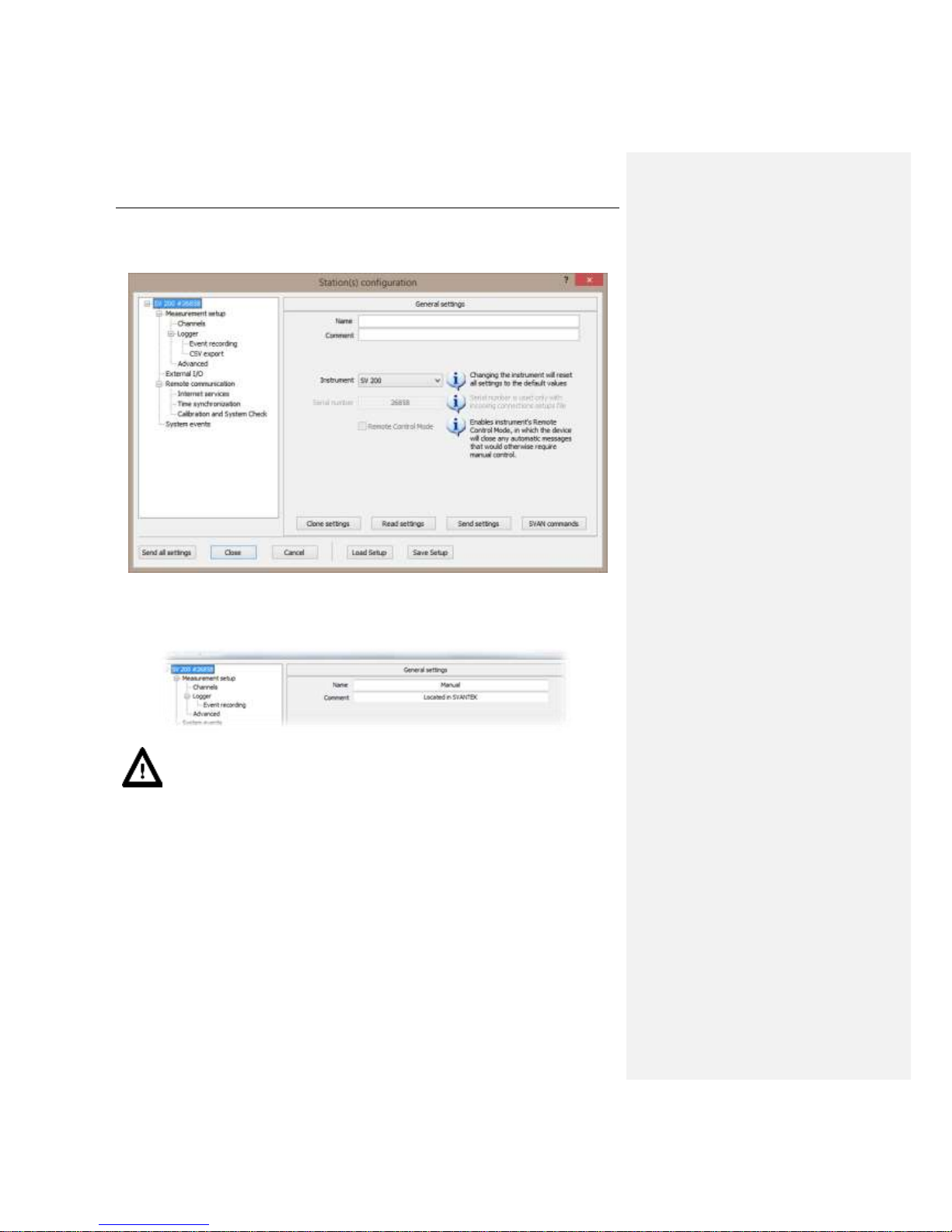
SV 200 USER MANUAL 57
6. Station configuration window will appear. It allows the user to modify general instrument
settings, measurement setup, external I/O setup, internet services and system events settings.
Remote communication setup is available only for USB connection.
6.2 General settings
In general settings tab the user can enter the Name and Comment of the station. This can be useful for
organizing multiple measurement devices.
Notice: Name and Comment appear on the alarm emails sent by Remote
Communication service. For further information see Chapter 0.
Page 58

SV 200 USER MANUAL 58
6.3 Measurement setup
The Measurement setup tab consists of the following parameters: the measured function (Level meter,
1/1 octave or 1/3 octave), the delay of the start of measurements (Start delay), the integration period
/ measurement run time (Integration period), the RMS detector type (RMS integration), the number
of repetitions of measurement cycles (Repetition cycles) and the frequency response of the
microphone (Outdoor filter).
6.3.1 Measurement function
The main function of the instrument is the measurement of Sound pressure broad band level (Level
Meter). The Level Meter function provides the user with functions meeting the standard IEC 61672:2013
for Type 1 accuracy.
The user may also use 1/1 and 1/3 real time octave band
frequency analysis functions. These functions extend the
main Level Meter functions of the instrument, because the
selected 1/1 and 1/3 octave analysis is performed together
with all calculations of Level Meter functions.
After entering the Function list, the set of the available
functions appears on the display: Level Meter, 1/1 Octave
and 1/3 Octave. In order to select the required function the
user has to enter the Function list and click suitable item.
6.3.2 Start delay
The Start Delay setting defines the delay period from the
moment of pressing power button, clicking Start
measurement button in Web Interface or SvanPC++ Remote
Communication module to the start of the actual
measurement (the digital filters of the instrument constantly
analyse the input signal even when the measurement is
stopped). This delay period can be set from 0 s to 60 s with
1 s steps.
Measurement function
Start delay
RMS integration
Integration period
Outdoor filter
Repetition cycles
Page 59

SV 200 USER MANUAL 59
6.3.3 Integration period
The Integration Period setting defines the period during
which the signal is being measured (integrated) and stored
as the set of Summary Results (SR).
The measurement will stop automatically after this period.
When the Repetition cycle is greater than one the
measurement will start again. The definitions of the
measurements results in which the integration period is user
is given in Appendix D.
6.3.4 RMS Integration
The RMS Integration setting defines the detector type for
the calculations of the Leq, LEPd, LN% and SEL functions.
Two options are available: linear and exponential. The
formulae used for the Leq calculation are given in Appendix
D.
Selecting Linear is required to obtain the true RMS value of
the measured signal. When this option is selected the value
of the Leq, LEPd, LN% and SEL functions do not depend
on the detector time constant: Fast, Slow or Impulse.
Selecting Exponential enables the user to fulfill the requirements of other standards for the time
averaged Leq measurements. When this option is selected the calue of the Leq, LEPd, LN% and SEL
functions depends on the detector time constant: Fast, Slow or Impulse.
6.3.5 Repetition cycles
The Repetition cycles setting defines the number of cycles
(with the measurement period defined by Integration
Period) to be performed by the instrument, The Repetition
cycles number values are within the limits [1, 1000]. Infinite
repetition cycles number can also be set.
6.3.6 Outdoor filter
The Outdoor filter setting enables the user to select the
appropriate frequency response compensation filter. The
characteristic of the outdoor filter depends on the
application: environmental (the acoustic signal is parallel to
the microphone’s grid) or airport (the acoustic signal is
perpendicular to the microphone’s grid). The frequency
characteristic of the designed filters is given in Appendix D.
Page 60

SV 200 USER MANUAL 60
6.4 Channels
This tab enables the user to adjust filter and RMS detector settings for each acoustic profile individually,
which effectively gives three separate results with different filter and detector setting. Frequency
weighting filter for 1/1 & 1/3 octave analysis can also be set.
6.4.1 Weighting filter selection
• Z type 1 according to IEC 61672-1 standard,
• A type 1 according to IEC 651 and IEC 61672-1
standards,
• C type 1 according to IEC 651 and IEC 61672-1
standards.
6.4.2 RMS detector selection
The following RMS detectors are available in the instrument:
Impulse, Fast and Slow.
Detector & filter settings
Spectrum filter setting
Page 61

SV 200 USER MANUAL 61
6.5 Logger settings
This tab enables the user to set the logger functions: the recording of the measurement time history
results, time history step and splitting.
6.5.1 Logger on
The Logger on switches on and off the functionality, which
enables the user to save selected results from the three user
profiles with the period defined in Logger step.
When Logger on option is selected also the Summary
results are also recorded. Summary results contain all
information available for current measurement function.
They are saved with the period specified in Integration
period box (see Section 6.3.3).
Notice: When Logger on is not selected no measurement results will be stored in
SV200.Switch off only when necessary.
6.5.2 Logger step
The Logger step defines the period of the data logging in a
file. It can be set from 2 milliseconds to 1 second in 1, 2, 5
sequences, from 1 second to 59 second, from 1 minute to
59 minutes and 1 hour.
Splitting mode
Logger results
Logger on
Logger meteo
Logger step
Page 62

SV 200 USER MANUAL 62
6.5.3 Logger meteo
The Logger meteo check-box controls saving results from
SV205B weather station (sold separately). The results are
saved according to Logger step setting, unless it is smaller
than 1s. In such case weather data will be stored in the result
file each second.
The SV205B cooperating with Gill WindSonic wind-meter allows the user to record humidity, pressure,
temperature, wind speed and direction values. It is also equipped with rain sensor.
6.5.4 Splitting mode
The Splitting mode selector enables the user to choose
maximum length of each individual result *.svn file. If the
measurement is still carried out, the file is closed and the
results are saved in the next file.
At specific time option splits files at specified time of day. It
is possible to define up to six settings.
6.5.5 Logger results
The Logger Results list enables the user to
activate the results for three independent user
defined profiles, which will be recorded to the
logger file during measurement. Measurement
parameters for each profile are defined in
Channels section (see Chapter 6.4).
Page 63

SV 200 USER MANUAL 63
6.6 Event recording
The Event Recording functionality enables the user to activate and set the parameters of event
waveform signal recording on the instrument’s SD Card.
6.6.1 Recording type
The Recording type setting enables the user to choose
where the recording is going to be stored.
In Wave recording mode recordings will take form of
separate PCM (*.wav) files stored on the SD Card of the
SV 200 alongside logger files.
In Event recording mode the recordings will be stored
inside logger files. Audio recording in logger file is indicated
by the Audio marker. The recording can be later exported
from the logger file in PCM format.
Notice: PCM audio recordings take up a lot of storage space and therefore bandwidth
during data download. Be careful using audio recordings especially with 3G modem
version of SV 200.
6.6.2 Recording settings
The Recording settings section enable the user to choose sampling frequency and format (only
available in wave recording mode) of the recording.
It is possible to select one of the three following sampling rates:
• 12 kHz,
• 24 kHz,
• 48 kHz.
Choosing higher sampling rate ensures recording of higher frequency but at the same time increases
file size.
Recording type
Recording settings
Trigger settings
Trigger type
Page 64

SV 200 USER MANUAL 64
6.6.3 Trigger type
The Trigger type list enables the user to set the parameters
for the recording trigger.
Triggering is switched on if one of its seven available modes
is selected: Continuous, Slope +, Slope –, Level +, Level –,
Gradient + or Integration period.
When Continuous trigger type is active, whole
measurement will be recorded.
Slope type trigger
In the case when Slope + is selected, the recording starts when the rising result value passes above the
level determined in the Level list. When Slope – is selected, the measurement starts when the falling
result value passes below the level determined in the Level list. The recording is stopped after a period
determined in Recording Time list. The triggering condition checking time is determined in Step list.
Level type trigger
The recording is active only when the result value has a level greater/lower than that determined in the
Level list. The recording is stopped after a period determined in Recording Time list regardless of the
result value. The triggering condition checking time is determined in Step list.
Gradient type trigger
The recording is active only when the result value has a level greater than that determined in the Level
list and the gradient of the signal is greater than determined in the Gradient list. The recording is stopped
after a period determined in Recording Time.
Page 65

SV 200 USER MANUAL 65
6.7 CSV export
The CSV export functionality allows direct export of measurement data into CSV files stored on the
instrument’s SD card. The Result selector enables the user to select results to export from each profile
individually. Maximum, minimum and average spectra for each integration period can also be exported.
The file structure of a generated CSV is shown in the table below.
Section
File contents
File header
// **********************************************************************
// CSV file version, 1.18
// Created, 11/01/2015, 20:43:24
// Unit, 200, SN, 26858
// Firmware, 1.20.7, 14/11/2014
// Corresponding logger file name, L1.SVL
// Device function, SLM
// Integration time, 00:00:01
// Leq integration, linear
// Outdoor filter, environmental
// Profile 1, A, FAST
// Profile 2, C, FAST
// Profile 3, Z, FAST
// Statistical levels, 1, 10, 20, 30, 40, 50, 60, 70, 80, 90
// CSV save mask, 0FFF, 0FFF, 0FFF, 7
// SLM results, profile 1, TIME, PEAK, MAX, MIN, SPL, LEQ, SEL, Lden, Ltm3, Ltm5, Lnn, OVL
// SLM results, profile 2, TIME, PEAK, MAX, MIN, SPL, LEQ, SEL, Lden, Ltm3, Ltm5, Lnn, OVL
// SLM results, profile 3, TIME, PEAK, MAX, MIN, SPL, LEQ, SEL, Lden, Ltm3, Ltm5, Lnn, OVL
// **********************************************************************
Record number
// Record No, 1
Time sgnature
DT, 11/01/2015, 20:43:25
Measurement
data
P1, 1, 56.0, 42.7, 39.6, 42.7, 41.5, 41.5, 46.5, 42.7, 42.7, 42.9, 42.8, 42.6, 42.4, 42.2, 42.0, 41.0, 40.5, 40.0, 38.5, 0
P2, 1, 62.3, 53.9, 47.8, 53.9, 49.8, 49.8, 54.8, 53.9, 53.9, 51.9, 51.5, 51.0, 50.5, 50.0, 49.5, 49.0, 48.5, 48.0, 47.5, 0
P3, 1, 66.7, 59.0, 47.3, 59.0, 57.5, 57.5, 62.5, 59.0, 59.0, 59.9, 59.0, 58.5, 58.0, 57.7, 57.5, 57.2, 57.0, 56.6, 56.3, 0
Record number
// Record No, 2
Time sgnature
DT, 11/01/2015, 20:43:26
Measurement
data
P1, 1, 56.9, 45.4, 41.4, 45.4, 42.8, 42.8, 47.8, 45.4, 45.4, 46.9, 46.0, 43.0, 42.7, 42.5, 42.2, 42.0, 41.6, 41.3, 41.0, 0
P2, 1, 63.3, 52.6, 47.9, 52.6, 50.4, 50.4, 55.4, 52.6, 52.6, 53.9, 53.6, 53.3, 53.0, 48.7, 48.5, 48.2, 48.0, 47.6, 47.3, 0
P3, 1, 67.8, 59.2, 54.0, 59.2, 56.6, 56.6, 61.6, 59.2, 59.2, 59.9, 59.5, 59.0, 57.0, 55.6, 55.3, 55.0, 54.6, 54.3, 54.0, 0
Record number
// Record No, 3
Time sgnature
DT, 11/01/2015, 20:43:27
Measurement
data
P1, 1, 57.6, 41.7, 37.6, 41.7, 39.1, 39.1, 44.1, 41.7, 41.7, 42.9, 42.0, 41.0, 39.0, 38.7, 38.5, 38.2, 38.0, 37.5, 37.0, 0
P2, 1, 62.9, 53.2, 49.6, 53.2, 50.9, 50.9, 55.9, 53.2, 53.2, 54.9, 54.0, 50.8, 50.7, 50.5, 50.4, 50.2, 50.1, 50.0, 49.5, 0
P3, 1, 68.9, 64.0, 56.9, 64.0, 61.9, 61.9, 66.9, 64.0, 64.0, 63.9, 63.6, 63.3, 63.0, 62.0, 61.6, 61.3, 61.0, 60.5, 60.0, 0
…
…
Notice: CSV files can take up a lot of storage space and therefore bandwidth during data
download. Be careful using this feature especially with 3G modem version of SV 200.
Result selector
Page 66
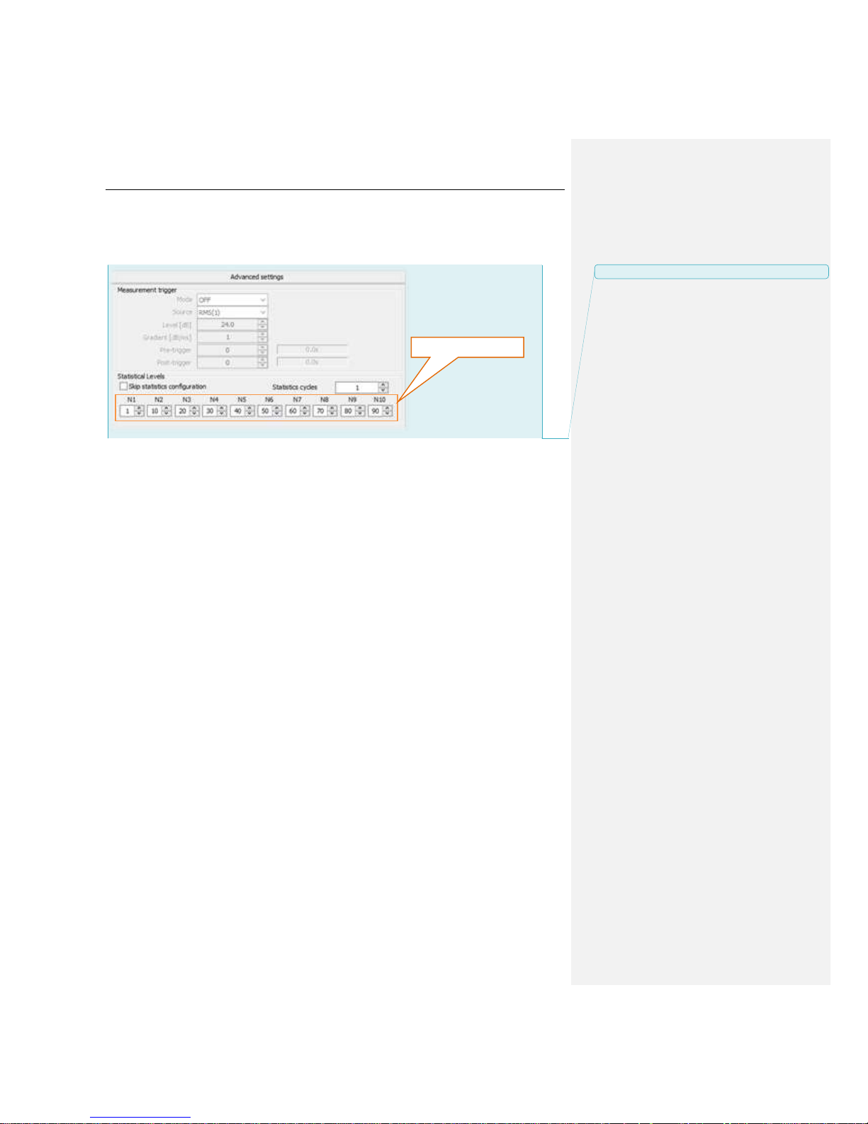
SV 200 USER MANUAL 66
6.8 Advanced
The Advanced settings tab enables the user to define ten statistical levels, named from N1 to N10, to
be calculated and saved in the measurement files.
All values have to be in the integer range of 1 to 99. Each value can be set independently from the
others.
Statistics selector
Z komentarzem [MB5]: Statistic cycles ?
Page 67

SV 200 USER MANUAL 67
6.9 External I/O
The External I/O tab allows the user to select the device connected to the SV 200 via the Ext. I/O
socket.
6.9.1 External device
The External device selector list contains devices possible
to connect via Ext. I/O socket.
• User interface denotes SV 200CU. For more
information on the SV 200CU see Chapter 9.
• Meteo denotes SV 205B meteo module.
• GPS denotes SV 58 GPS module.
Selecting either one of the devices alters the behavior of the
Device settings.
6.9.2 Device settings
For User interface option the user can configure Baud rate
and Timeout RS 232 connection parameters.
Since the SV 200CU has a fixed baud rate of 115200 bytes
per second. Default time out value is equal to 5 s. The SV
200 should be operating with the same values.
For the Meteo option the user can configure number of wind
statistics sectors.
Wind statistics include wind direction, maximum wind speed
and average wind speed distributions.
External device selector
Device settings
Z komentarzem [MB6]: Omówić z SD
Page 68
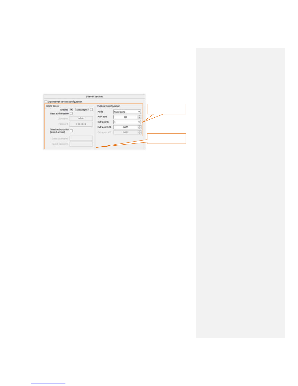
SV 200 USER MANUAL 68
6.10 Internet services
The Internet services tab enables the user to configure WWW Server and Multi port features of the
SV 200.
6.10.1 WWW Server
The WWW Server enables the user to control the SV 200 using web browser on any device. For more
information on WWW Server see Chapter 7.
In this section the user can enable or disable the WWW server feature by checking or unchecking
Enabled box.
Enabling Static pages option causes the Web page contents to download from the instrument. It
decreases the performance for the devices with the Internet access, but improves it significantly for the
devices that currently are not connected to the Internet.
WWW Server
configuration
Multi-port configuration
Page 69
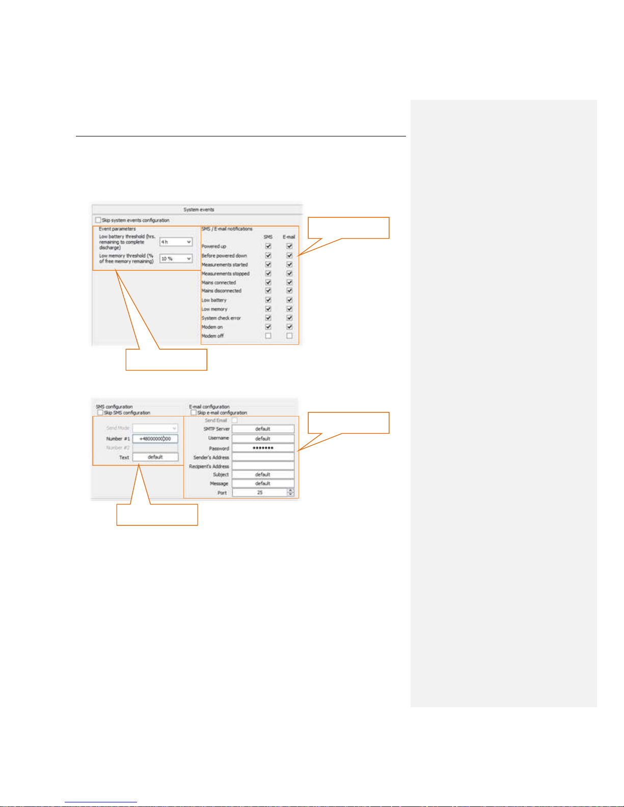
SV 200 USER MANUAL 69
6.11 System events
The SV 200 can automatically report certain system events by email or text message. List of reported
events can be found in System events section.
Text message format and recipient and email account settings are configured in Alarm settings section.
Battery and memory
thresholds
Events selector
Text message format
and recipient
Email account settings
Page 70

SV 200 USER MANUAL 70
6.12 Time synchronization
The SV 200 offers sophisticated time synchronization features, including automatic and manual daylight
saving time adjustments.
1. To enable the time synchronization feature in Time
synchronization settings section choose suitable
time synchronization protocol. By default NTP protocol
should be set.
2. To make synchronization automatic select desired
synchronization mode. Daily time synchronization is
recommended.
3. In the Time zone settings section select suitable Time
zone and Daylight Saving Time Standard. European
and US/Canadian standards are implemented in the
instrument.
4. If different daylight saving time rules apply use Custom Daylight Saving Time section.
Notice: There are four time synchronization servers predefined in the Time
synchronization settings. Do not change these settings unless the servers are
unavailable in the instrument’s network or a custom server is needed.
Time zone settings
Time synchronization
settings
Custom daylight saving
time setting
Page 71

SV 200 USER MANUAL 71
6.13 Calibration & System Check
The SV 200 is fitted with an Automatic calibration and Automatic system check features. This
section enables the user to configure details of those features.
6.13.1 Automatic calibration
When the Automatic calibration is enabled mounting the acoustic calibrator on the instrument’s
microphone automatically starts the calibration procedure.
Such operation requires pairing the calibrator with the instrument by entering Calibration Level from
the calibrators calibration certificate. For more information on automatic calibration feature see
Chapter 3.6.
Notice: Calibration Level programmed into the SV 200 remains constant. Remember to
perform calibration with the acoustic calibrator generating exactly the same level as the
configured calibration level.
6.13.2 Automatic system check
When the Automatic system check feature is enabled the calibration factor of the instrument will be
periodically verified using built-in electrostatic actuator. The user can specify the hour and a weekday of
automatic system checks.
To activate automatic system check select Enabled (no Factor update) option from a Mode
dropdown list.
To schedule automatic system checks choose weekday and select time of system check from the
dropdown list.
Notice: System check cannot be considered as a calibration. Calibration factor will not
be updated during Automatic system check procedure.
Notice: Measurements are not stopped for the Automatic system check procedure.
Noise levels induced by the actuator will be recorded in the measurement file!
Automatic calibration
settings
Automatic system
check settings
Z komentarzem [MB7]: Czy tak?
Page 72

SV 200 USER MANUAL 72
6.13.3 Logging
Results of calibration (both manual and automatic) and also automatic system check are stored in the
Calibration and system check history file on the instrument’s SD card. Log file name is C.TXT. The
file can be downloaded with SVAN Files (see Chapter 8.1.4) or WEB interface (see Chapter 7.2) and
then opened in any text editor, such as MS Notepad. Maximum allowed size of log file is specified in
Automatic calibration settings section.
6.14 FTP data transfer
The FTP data transfer is used to transfer measurement data and setup files between the SV 200 and
any FTP server. For more information on FTP data transfer concept see Chapter 8.2.
1. FTP push and pull functionalities can be individually switched on with the FTP push / FTP pull
checkboxes.
2. Enter FTP server address, port, remote directory and account credentials in the FTP server
settings section. Only unencrypted connections are supported.
3. For the FTP push feature to work select result file types to upload on the FTP server in the Results
section.
4. For the FTP pull feature to work specify filename of the setup file that is going to be uploaded on
the instrument in the Pull files section.
5. Time periods section specifies time intervals of subsequent push and pull operations.
FTP server settings
Results
Pull files
Time periods
FTP push/pull selection
Page 73

SV 200 USER MANUAL 73
7 WEB INTERFACE
When enabled, and the instrument is properly configured (both in 3G and Wi-Fi versions), SV 200 offers
the user easy means of accessing the instrument’s settings, results and status information via a Web
browser.
The default web page of the instrument features four tabs that cover a different area of information:
• Live data
• File storage
• Configuration
• Status
Notice: The WEB Interface must be enabled during initial instrument configuration. See
Chapter 0.
7.1 Live data page
Live data displays the information about the current measurement. It serves as a welcoming page for
the instrument and includes a variety of information. Information such as station name, project name
and location serve to quickly name tag the instrument. The map field is used to show the instrument’s
position. The map is downloaded in parts from www.openstreetmap.org and should the site be
inaccessible by the browser, proper information will be displayed.
7.1.1 Overview section
The main feature of this section is three result displays that can be adjusted by the user to show chosen
results for each measurement profile. The results are being refreshed every second, creating a dynamic
“live data” view. Information about the profile’s filter and detector setting is also included.
The flashing LED in the upper corner denotes the instrument’s current measuring state. The green color
means the measurement is RUNNING and red color means the measurement is STOPPED.
status LED
station name
project name
location data
RTC clock
results
Page 74

SV 200 USER MANUAL 74
Notice: The flashing LED is visible on all four tabs of the Web Interface, to conveniently
provide information on measurement status at all times.
7.1.2 Summary Results section
The Summary Results section gives the user the overview of selected measurement function results
from current and previous integration period. Function selector enables the user to select six different
results from any measurement profile for display.
function selector
result display
integration time
Page 75
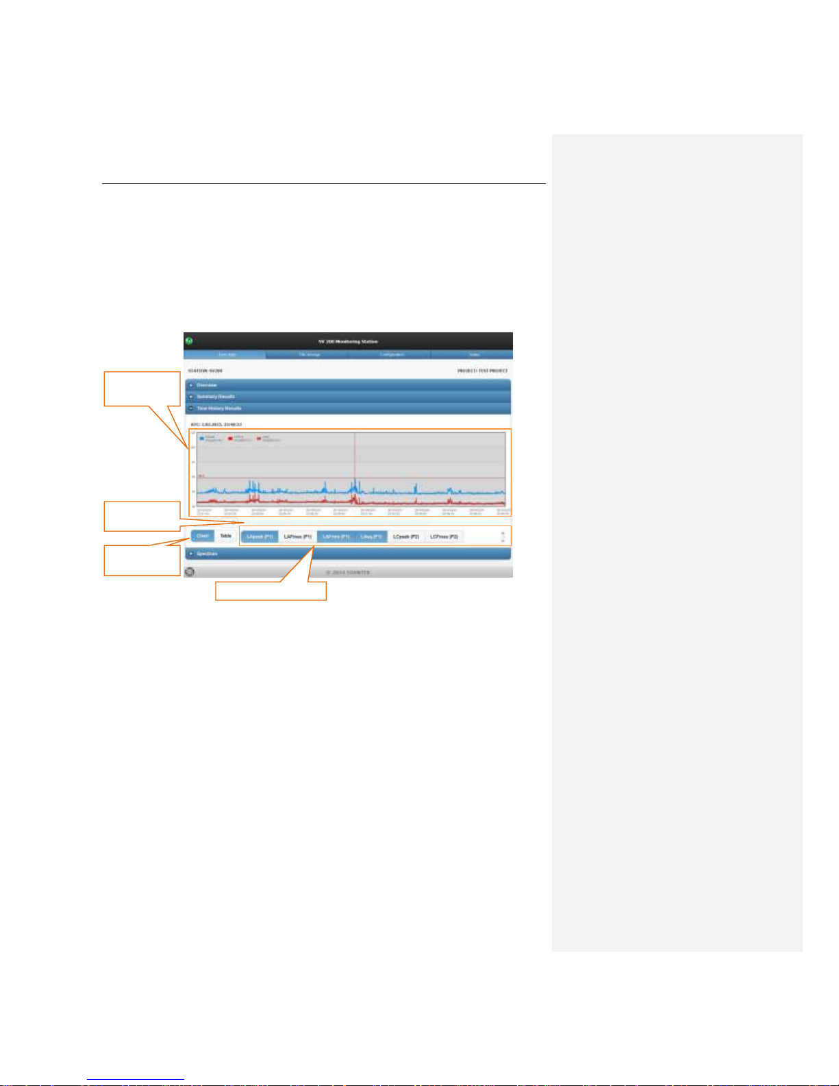
SV 200 USER MANUAL 75
7.1.3 Time History Results section
The Time history section enables the user to view time history of the functions selected in function
selector. There are four functions (Leq, L
peak, Lmax
and L
min
) available to select for each measurement
profile.
It is possible to choose between viewing selectable number of recorded samples from the beginning of
the measurement and viewing predefined number of recorded samples from the end of the file using
Last checkbox.
time history
display
function selector
chart/table
switch
samples
number
Page 76

SV 200 USER MANUAL 76
7.1.4 Spectrum section
The Spectrum section displays spectrum from current integration period. The spectral information is
based on the analysis type currently set in the instrument and the user can browse it both in chart or
table form. Similar as with main results, spectrum is refreshed every second.
Notice: Spectrum can only be displayed, when Octave 1/1 or Octave 1/3 measurement
functions has been selected before the start of the measurement. To set desired
measurement functions using the Web Interface see section 8.3.
spectrum section
chart/table
switch
Page 77

SV 200 USER MANUAL 77
7.2 File storage page
File storage is a listing of the files recorded in the instrument’s SD card storage. The listing includes
only the files from a single folder and it initially shows the content of the SV 200’s currently set working
directory. By clicking on the folders or using the “folder up” button, the user can navigate through the
folder structure.
The File storage page also enables the user to download each measurement file by clicking on its
name.
This page does not refresh by itself – should the user wish to keep up to date with the file listing and its
details, a page refresh is required.
Page 78

SV 200 USER MANUAL 78
7.3 Configuration page
Configuration page contains several sections, each allowing to view and adjust part of the instrument’s
settings. In order to toggle a section on click corresponding button.
A the bottom of the page are two buttons: “Start/stop measurement” and “Apply settings”. The former is
used to start and stop the instrument’s measurement while the latter will trigger a procedure that will
send the currently selected settings on the page to the instrument. It should be noted that settings cannot
be changed when the measurement is running. It is necessary to apply any changes that had been
made in instrument’s configuration before closing the Configuration page.
1. If the measurement is click Stop measurements button.
2. Alert message will appear. Confirming will stop current
measurement
3. Click the Apply setting button to save all changes.
Instrument’s settings are divided into following sections:
• Filters & detectors,
• Storage,
• CSV Export,
• Audio Events,
• Real Time Clock,
• Calibration and System Check,
• FTP Data Transfer,
• Auxiliary settings,
• Firmware update.
section buttons
apply settings button
stop/start measurements button
Page 79

SV 200 USER MANUAL 79
7.3.1 Filters & detectors section
In Filters & detectors, the user can adjust frequency weighting filter and RMS detector settings for each
profile and frequency weighting filter for spectrum analysis.
Filters & detectors section enables the user to configure following parameters of the instrument:
Integration type
The Integration type setting defines the detector
type for the calculations of the Leq, LEPd, LN% and
SEL functions. Two options are available: linear and
exponential. The formulae used for the Leq
calculation are given in Appendix D.
Selecting Linear is required to obtain the true RMS value of the measured signal. When this option
is selected the value of the Leq, LEPd, LN% and SEL functions do not depend on the detector time
constant: Fast, Slow or Impulse.
Selecting Exponential enables the user to fulfill the requirements of other standards for the time
averaged Leq measurements. When this option is selected the calue of the Leq, LEPd, LN% and
SEL functions depends on the detector time constant: Fast, Slow or Impulse.
This setting corresponds to RMS Integration in SvanPC++ RC Station Configuration (see Chapter
6.3.4).
Filter
The Filter setting enables the user to select frequency weighting filter
for each of three available measurement profiles and also for
spectrum. There are three filters available to choose:
• Z type 1 according to IEC 61672-1 standard,
• A type 1 according to IEC 651 and IEC 61672-1 standards,
• C type 1 according to IEC 651 and IEC 61672-1 standards.
This setting corresponds to Weghting filter in SvanPC++ RC Station Configuration (see Chapter
6.4.1).
integration type setting
profile filter settings
profile detector settings
spectrum filter setting
Page 80

SV 200 USER MANUAL 80
Detector
The following RMS detectors are available in the instrument:
Impulse, Fast and Slow.
This setting corresponds to RMS Detector in SvanPC++ RC
Station Configuration (see Chapter 6.4.2).
7.3.2 Storage section
In the Storage section the user can select which results will be recorded in time history file and
determine intervals in which both time history results and summary results will be recorded. Also the
maximum duration of individual logger file can be set.
Logger interval
The logger interval setting defines the period of the data logging
in a file. It can be set from 2 milliseconds to 1 second in 1, 2, 5
sequences, from 1 second to 59 second, from 1 minute to 59
minutes and 1 hour.
This setting corresponds to Logger Step in SvanPC++ RC
Station Configuration (see Chapter 6.5.2).
Logger interval
Summary results
interval
Logger Results
Spectrum settings
Logger splitting
Page 81

SV 200 USER MANUAL 81
Summary results interval
The summary results interval setting defines the period during
which the signal is being measured (integrated) and stored as
the set of Summary Results (SR).
The measurement will stop automatically after this period. When
the Repetition cycle is greater than one the measurement will
start again. The definitions of the measurements results in which
the integration period is user is given in Appendix D.
This setting corresponds to Integration period in SvanPC++
RC Station Configuration (see Chapter 6.3.3).
Logger Results
The Logger Results list enables the user to activate the results
for three independent user defined profiles, which will be
recorded to the logger file during measurement. Measurement
parameters for each profile are defined in Filters & detectors
section (see Chapter 7.3.1).
This setting corresponds to Logger Results in SvanPC++ RC
Station Configuration (see Chapter 6.5.5).
Spectrum settings
The main function of the instrument is the measurement of Sound pressure broad band level (Level
Meter). The Level Meter function provides the user with functions meeting the standard IEC 61672:2013
for Type 1 accuracy.
The user may also use 1/1 and 1/3 real time octave band
frequency analysis functions. When selected the
frequency analysis results are always calculated for each
Summary Results interval. Optionally, after selecting
Include spectrum in time history logger the spectrum
will be calculated for each logger step.
This setting corresponds to Measurement Function in
SvanPC++ RC Station Configuration (see Chapter
6.3.1).
Logger splitting
The Splitting mode selector enables the user to choose
maximum length of each individual result *.svn file. If the
measurement is still carried out, the file is closed and the results
are saved in the next file.
Every day option splits files at specified time of day. It is possible
to define up to six settings.
This setting corresponds to Measurement Function in
SvanPC++ RC Station Configuration (see Chapter 6.3.1).
Page 82
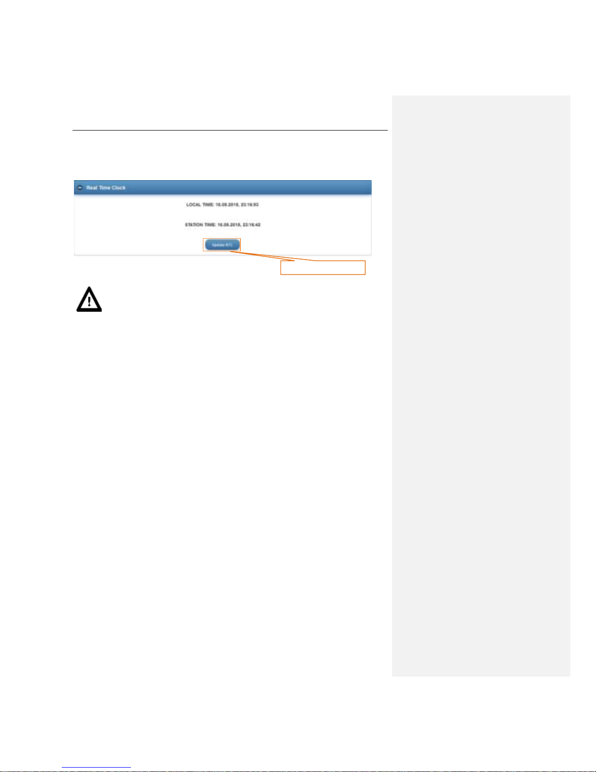
SV 200 USER MANUAL 82
7.3.3 Real Time Clock
Displays the current time in the instrument as compared to the local time of the PC. The “Update RTC”
button allows the user to update the instrument’s time to the PC’s current time.
Notice: The measurement must be stopped before updating RTC.
Update RTC
Page 83

SV 200 USER MANUAL 83
7.3.4 Calibration and System Check
This tab enables the user to configure automatic calibration and system check as well as perform manual
checks.
Auto calibration
Auto calibration settings section allows to remotely activate or deactivate auto calibration feature
and set maximum size of calibration log file. More detailed configuration involving setting calibration
level must be performed using SvanPC++ (see Chapter 6.13).
Automatic system check
Automatic system check settings section allows to remotely activate and schedule or deactivate
automatic system check feature.
When the Automatic system check feature is enabled the calibration factor of the instrument will be
periodically verified using built-in electrostatic actuator. The user can specify the hour and a weekday of
automatic system checks.
Notice: System check cannot be considered as a calibration. Calibration factor will not
be updated during Automatic system check procedure.
Automatic calibration settings
Current calibration factor
Automatic system check settings
Manual system check
Actuator switch
Last check result
Page 84

SV 200 USER MANUAL 84
To activate automatic system check select Enabled (no Factor
update) option from a dropdown list.
To schedule automatic system checks choose weekday and
select time of system check from the dropdown list.
This setting corresponds to Automatic system check in
SvanPC++ RC Station Configuration (see Chapter
6.13.26.3.1).
Manual system check
Do system check button performs one-time system check.
Result will be recorded in an auto calibration and system check
log file.
Manual actuator control
Enable actuator button enables and disables electrostatic
actuator of the SV 200. After activating the actuator the wave icon
will appear next to the status LED in the top left corner of the
WEB interface page indicating activity of the actuator.
After enabling the actuator while the measurement is running go
to the Live data page to quickly view the results. Sound level
induced by the actuator will be stored in the measurement file.
Page 85

SV 200 USER MANUAL 85
7.3.5 FTP Data Transfer
The FTP data transfer is used to transfer measurement data and setup files between the SV 200 and
any FTP server. For more information on FTP data transfer concept see Chapter 8.2.
1. FTP push and pull functionalities can be individually switched on with the FTP push / FTP pull
checkboxes.
2. Enter FTP server address, port, remote directory and account credentials in the FTP server
settings section. Only unencrypted connections are supported.
3. For the FTP push feature to work select result file types to upload on the FTP server in the Results
section.
4. For the FTP pull feature to work specify filename of the setup file that is going to be uploaded on
the instrument in the Pull files section.
5. Time periods section specifies time intervals of subsequent push and pull operations.
FTP server settings
Results
Pull files
Time periods
FTP push/pull selection
Page 86

SV 200 USER MANUAL 86
7.3.6 Auxiliary settings
Auxiliary settings, allow the user to enter information such as Station Name, Project Name and
Location Name, as well as enter the instrument’s geographical location in Latitude & Longitude
coordinates. The Lookup Location button triggers a procedure that uses an online lookup tool to
retrieve geographical location based on IP address and use the result to fill in Location Name and
Latitude & Longitude settings. It should be noted that such method of obtaining data is likely to produce
inaccurate results, due to the location actually pointing out to the internet service provider rather than
the actual location of the equipment.
7.3.7 Firmware update
Firmware update tab allows the user to upload new firmware on the instrument’s SD card and perform
update process remotely.
Complete update process is described in detail in Chapter 4.4. Before upgrade it is essential that the
proper firmware file is downloaded from SVANTEK website and the internet connectivity is stable.
Station name
Project name
Loaction name
GPS position
Lookup button
Browse button
Upload button
Load firmware button
Restart instrument button
Stored firmware selector
Page 87
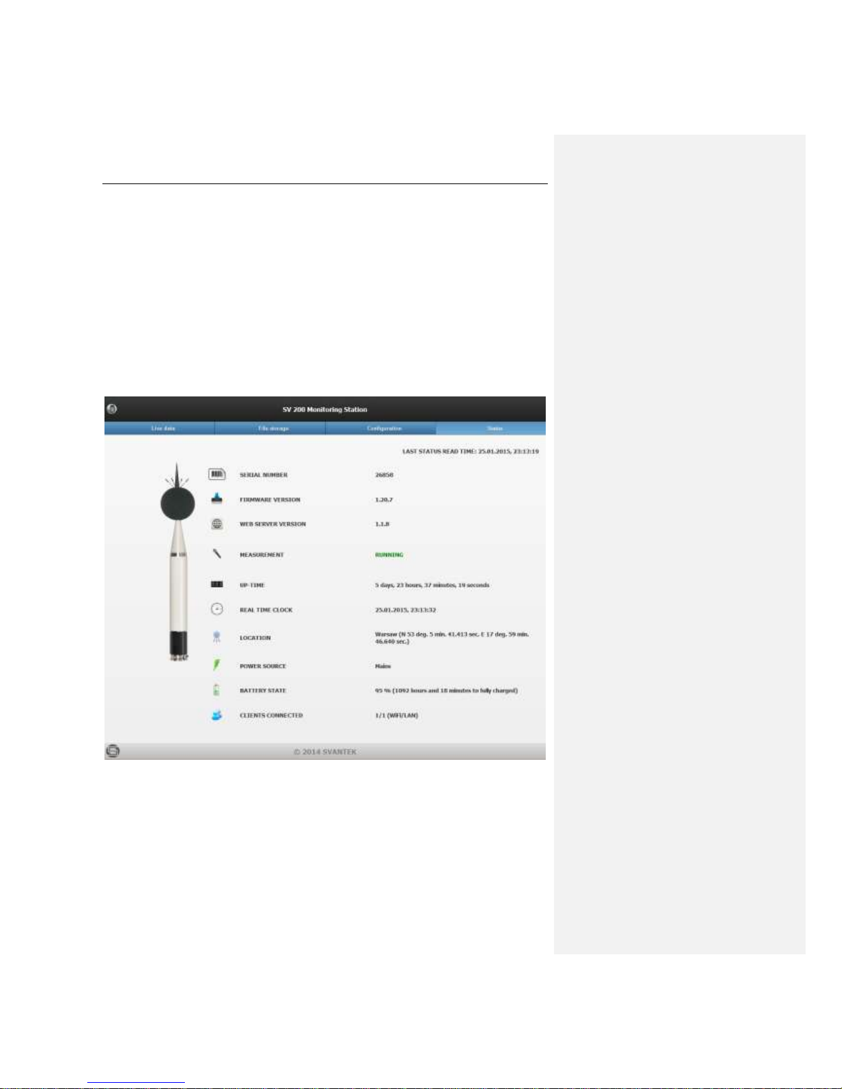
SV 200 USER MANUAL 87
7.4 Status page
Status page is used to display status information about the instrument. The default contents of the
status page are as follows:
• serial number
• firmware version
• web server version
• measurement state
• up-time
• real time clock
• location description
• power source
• battery state
• battery voltage.
Page 88

SV 200 USER MANUAL 88
8 DATA COLLECTING
This chapter describes how to obtain data stored in the SV 200 instrument using Internet connection.
Three possible communication modes are presented SVAN PC++ with Remote Communication
module, FTP Client - direct upload to an FTP Server and data download using built-in WEB Interface.
8.1 SVAN PC++ (RC)
SvanPC++ with Remote Communication module offers the most versatile configuration and control of
the instrument, data collecting as well as publishing and presentation features. The RC module can
cooperate in a variety of modes and communication protocols therefore decreasing SV 200 network
requirements.
The Remote Communication module can operate in four
different data collecting modes:
• SVAN Files for direct, manual data download
• Automatic Files Download (AFD) for automatic data
download in specified time periods
• Continuous Logger Download (CLD) for constant
data download
• Live Results Preview for real-time data publishing and
presentation
Remote session mode is now obsolete and not supported. Using Remote session mode is not
recommended.
8.1.1 Beginning work with Remote Communication Center
The Remote Communication Module is controlled with Remote Communication Center window.
1. To access Remote Communication window locate suitable menu in SvanPC++.
2. Make sure that suitable Connection type is chosen. The default connection type is Internet
however when the instrument is connected to the PC with USB cable, connection type is
automatically changed to USB.
3. If there are no stations present in the Stations list new instrument must be configured. For
automatic configuration see Chapter 4.2.1. For manual configuration see Chapter Błąd! Nie
można odnaleźć źródła odwołania..
Page 89
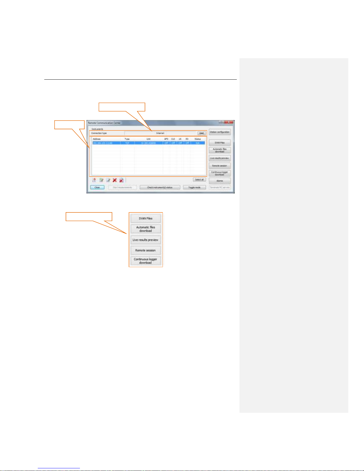
SV 200 USER MANUAL 89
4. Choose the instrument you wish to manage in Stations list. To select multiple instruments use
Ctrl+Click combination.
5. Click the button starting the desired data collecting mode.
connection type box
stations list
data collecting modes
Page 90

SV 200 USER MANUAL 90
8.1.2 Remote Communication Service
Automatic Files Download (AFD), Continuous Logger Download (CLD) and Live Results Preview run
within Remote Communication Service. It is a program operating in background regardless of whether
SvanPC++ is running or not. The user doesn’t even have to be logged in his Windows user profile. All
data collecting features of SvanPC++ are active once set up.
Remote Communication Service automatically resumes to its previous state after booting the PC.
The state of the Remote Communication Service can be easily monitored with SvanPC tray icon. It
becomes active when SvanPC++ application is not running.
Right-click on the icon expands the menu, allowing the user to view RC Service status, edit settings
(after opening SvanPC++ window), stop the service while waiting for all download tasks to finish or
terminate it immediately.
Double-clicking the SvanPC tray icon open SvanPC++ window enabling the user to edit the session’s
settings.
Notice: Changing Remote Communication Session settings requires administrative
privileges.
SvanPC tray icon
SvanPC tray menu
Page 91

SV 200 USER MANUAL 91
8.1.4 SVAN Files
SVAN Files is the simplest data collecting mode available in the RC module. This mode is suitable for
browsing the contents of the SV 200 SD card (including working directory), downloading or deleting
files, changing the working directory of the instrument (see Chapter 4.3) and WEB interface files update.
Notice: More information on SVAN Files can be found in SvanPC++ help file available
online:
http://svantek.com/lang-en/support/19/svanpc_software.html#PDF.
Browsing the contents of the device
SVAN Files window contains two main panes. The left pane displays contents of the instrument’s
memory. The right pane is used to browse local PC files.
Source selector enables the user to change source of files to display in the instrument navigation pane.
In case of SV 200 there are two sources available: SD disk and Internal RAM. No measurement data
can be stored in the Internal RAM memory of the instrument.
Notice: Choosing Internal RAM data source for the SV200 enables the user to access
the settings file with Setup file editor button. The file contains current detailed setup of
the instrument and should not be modified unless necessary.
By default SD card contains following directories:
• ARCHIVE, where old measurement files can be
stored,
• DATA, which is default working directory of the
instrument,
• FIRMWARE, which contains firmware packages
uploaded via WEB interface,
• SETUP, which contains setup files created by users.
The display filter can be used for selecting specific types of files to be displayed in the navigation pane.
instrument
navigation
pane
computer
navigation
pane
set RTC
button
source
selector
setup editor
button
display filter
destination
selector
Page 92

SV 200 USER MANUAL 92
Downloading files
1. In the instrument pane navigate to the directory where necessary measurement files are stored.
By default SVAN Files display current working directory of the instrument.
2. Select the Download type. By default binary SVL files are downloaded, however CSV files are
also available. Click expand button to see the details. Automatic merging is possible for binary files.
Use Merge option to download one file containing data from all selected files.
3. Select the files to download and click Download file(s) from SVAN button to copy files from
instrument’s memory to the PC. Multiple files can be selected using Ctrl and Shift buttons.
4. Refresh and download only new files button can be used to synchronize content of the
instrument’s memory with the local folder. Click that button to quickly download all files displayed
in the instrument navigation pane.
Changing the working directory
1. Navigate to the desired directory using the left pane. Create new directory if necessary.
2. Click Set as working folder button.
Uploading files
download type selector
Download file(s) from SVAN
Refresh and download only
new files
Set as working folder button
Page 93

SV 200 USER MANUAL 93
1. In the instrument pane navigate to the desired directory. By default SVAN Files display current
working directory of the instrument.
2. Files can be uploaded only to the current working directory of the instrument. Set the current
directory to be the working directory.
3. Select the files to upload in the right pane and click Upload file(s) to SVAN button to copy files
from to the PC instrument’s memory. Multiple files can be selected using Ctrl and Shift buttons.
Deleting files
1. In the instrument pane navigate to the desired directory. By default SVAN Files display current
working directory of the instrument.
2. If all SVAN files (logger and setup) are to be deleted click Delete All button.
3. If only selected files or files other than SVAN files are to be deleted, select them (multiple files can
be selected using Ctrl and Shift buttons, all files can be selected with Ctrl+A combination) and click
Delete button.
Updating RTC
SVAN Files enables the user to set the real time clock (RTC) of the SV 200. Current PC time can be
set as well as manually selected value.
To synchronize SV 200 time with the current PC time click Set RTC button. To enter other value click
Customize RTC button.
Upload file(s) to SVAN
Delete button
Delete all button
Set RTC button
Customize RTC button
Page 94

SV 200 USER MANUAL 94
8.1.5 Automatic Files Download
AFD (Automatic Files Download) is most commonly used data collecting method. In this mode
SvanPC++ automatically downloads data from any number of SV 200 monitoring stations and stores it
in selected local or remote directory.
Besides downloading files AFD performs other tasks such as:
• checking station status and sending notifications when one of the instruments requires attention,
• automatic time synchronization,
• remote system check with in-built electrostatic actuator,
• verification of instrument’s setups,
• deleting already downloaded files,
• publishing measurement data on the web server as a HTML file,
• uploading measurement files on the FTP server.
Notice: More information on Automatic Files Download can be found in SvanPC++ help
file available online:
http://svantek.com/lang-en/support/19/svanpc_software.html#PDF.
Basic information
Automatic Files Download runs as a Windows service. It does not require SvanPC++ application to
be running. Windows user who runs the AFD does not have to be logged on the PC. AFD automatically
resumes to its previous state after booting the PC.
AFD window displays list of stations running in AFD mode. For selected instrument station status
information is available. It displays basic information (instrument’s serial number and download path),
downloads statistics and summary for last downloading, clearing, settings and system checks.
Download
now button
Start/stop
button
Terminate
button
Station list
Station status
Options
button
Information
section
Progress
section
Page 95

SV 200 USER MANUAL 95
Information section displays time left for downloading and time left for clearing. These values depend
on Downloading period and Clearing period settings, described below. Also current state of the AFD
module is displayed.
Progress section refers to the station selected in station list. It displays stations type and serial number
and the name of the file currently being downloaded.
Configuration
To configure Automatic Files Download session settings click
Options button. Automatic files download options window will appear
allowing the user to make necessary adjustments.
Options button is only active when the AFD is not running.
Files to download, enables the user to choose which files are going to be downloaded with AFD.
Logger files containing measurement results are most commonly used.
Notice: CSV and WAVE files contain raw, uncompressed data. Make sure that bandwidth
is sufficient . If 3G modem is used make sure that SIM card data plan covers large
transfers.
Downloading period setting determines how often data from the SV 200 will be downloaded to the PC.
Five different periods can be chosen: hourly, daily (at specified hour), weekly (at specified weekday,
at specified hour), monthly (at specified day of month, at specified hour) and custom (specified time
interval between downloads). This setting applies only when Files to download are selected.
Automatic cleaning enables the user to choose which files are going to be erased from the instrument’s
memory after downloading.
Cleaning period setting determines how often data from the SV 200 will be erased. Five different
periods can be chosen: hourly, daily (at specified hour), weekly (at specified weekday, at specified
hour), monthly (at specified day of month, at specified hour) and custom (specified time interval
between downloads). This setting applies only when Automatic cleaning is active. Files are erased
from the instrument only after they had been previously downloaded with AFD.
files to
download
download
period
automatic
cleaing
cleaing
period
system
validation
file saving settings
publishing
settings
measurement
checking
Page 96

SV 200 USER MANUAL 96
System validation section enables the user to configure the following settings:
• system checks with built-in electrostatic actuator,
• validation of instrument settings after cleaning measurement files,
• validation of instrument settings after performing system check (if enabled),
• automatic synchronization of real time clock,
• verification of instrument settings.
Starting session
To start Automatic Files Download session click Start AFD button.
The AFD session will start with global settings configured in Options
window. Download will begin after the time defined in Downloading
period is over.
It is also possible to override global file saving settings of AFD session
by clicking File Conf. button next to each individual station in the
Station list.
To start Automatic Files Download session and download files from
the SV 200 immediately click Download now button.
Stopping session
To finish Automatic Files Download session after downloading all
measurement files click Stop AFD button.
To terminate Automatic Files Download session immediately,
without downloading all measurement files click Terminate button.
Notice: Terminating session may cause some measurement files to be incomplete.
However after restarting the session downloading will resume.
Page 97

SV 200 USER MANUAL 97
8.1.6 Continuous Logger Download
CLD (Continuous Logger Download) mode is used for continuous downloading of measurement data
from SV 200. Measurement results can be presented in real time while saving in selected local or remote
directory. In this mode only logger (SVL) files are downloaded.
Besides downloading files CLD performs other tasks such as:
• checking station status and sending notifications when one of the instruments requires attention,
• automatic time synchronization,
• remote system check with in-built electrostatic actuator,
• verification of instrument’s setups,
• deleting already downloaded files,
• publishing measurement data on the web server as a HTML file,
• uploading measurement files on the FTP server.
Notice: More information on Continuous Logger Download can be found in SvanPC++
help file available online:
http://svantek.com/lang-en/support/19/svanpc_software.html#PDF.
Basic information
Continuous Logger Download runs as a Windows service. It does not require SvanPC++ application
to be running. Windows user who runs the CLD does not have to be logged on the PC. CLD
automatically resumes to its previous state after booting the PC.
CLD window displays list of stations running in CLD mode along with the current state of each station.
The progress bar indicates activity of the CLD mode.
start/stop
button
terminate
button
station list
options
button
Page 98

SV 200 USER MANUAL 98
Configuration
To configure Continuous Logger Download session settings click
Options button. Continuous logger download options window will
appear allowing the user to make necessary adjustments.
Options button is only active when the CLD is not running.
Download step setting determines how often data from the SV 200 will be downloaded to the PC.
File saving settings section enables the user to configure basic settings for files download such as
download path, file naming rules and writing session log.
Daily data settings enables the user to configure the path where files downloaded from the instrument
will be copied after each day of measurements. Files may be automatically merged, if more than one
file is generated throughout the day.
Archivisation settings section enables the user to configure the path where all downloaded files are
copied for archivisation purposes. Files may be compressed into monthly zip file.
System validation & summary section enables the user to configure the following settings:
• time of station summary (hourly, daily, weekly or monthliy)
• clearing downloaded loggers from the instrument during measurements
• system checks with built-in electrostatic actuator,
• automatic synchronization of real time clock,
• verification of instrument settings during station summary.
Publish WWW/SVN Upload section enables the user to configure basic
settings for HTML publishing of the results and FTP uploads. Detailed
settings can be configured for each individual station by clicking WWW
button which becomes visible in station list.
Configure FTP button enables the user to input configuration for FTP server which is going to be used
for data upload.
Starting session
To start Continuous Logger Download session click Start button.
The CLD session will start immediately with global settings configured
in Options window.
download
step
daily data
settings
archivisation
settings
system
validation &
summary
file saving settings
publishing
settings
Page 99
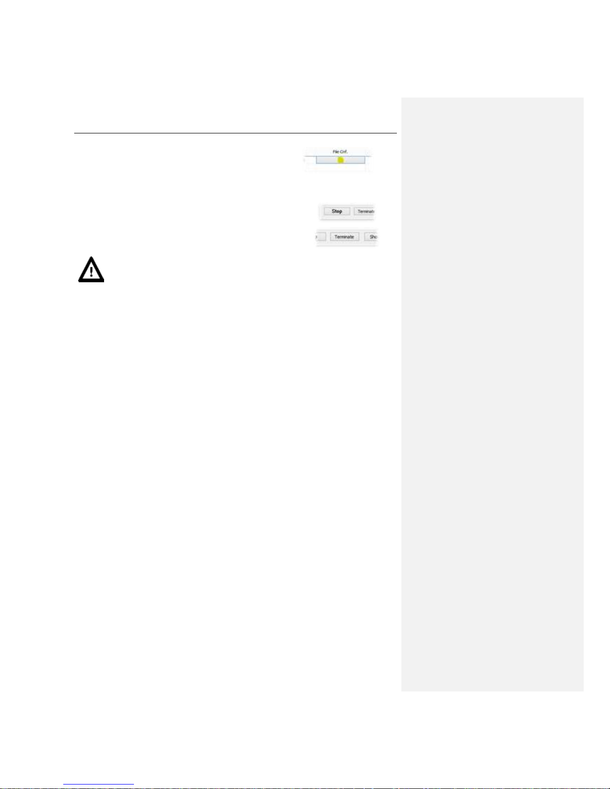
SV 200 USER MANUAL 99
It is also possible to override global file saving settings of CLD session
by clicking File Conf. button next to each individual station in the
Station list.
Stopping session
To finish Continuous Logger Download session after downloading
all measurement files click Stop button.
To terminate Continuous Logger Download session immediately,
without downloading all measurement files click Terminate button.
Notice: Terminating session may cause some measurement files to be incomplete.
However after restarting the session downloading will resume.
Page 100

SV 200 USER MANUAL 100
8.1.7 Live Results
Live Results mode is used to easily view current SV 200 results without necessity to save the
measurement files on the computer. This mode is capable of publishing HTML results on the WEB
server and also uploading measurement files from the instrument directly on the FTP server.
Notice: More information on Live Results can be found in SvanPC++ help file available
online:
http://svantek.com/lang-en/support/19/svanpc_software.html#PDF.
Basic information
Live Results runs as a Windows service. It does not require SvanPC++ application to be running.
Windows user who runs the LR does not have to be logged on the PC. LR automatically resumes to its
previous state after booting the PC.
Live Results window displays list of stations running in LR mode along with the results selected for
display.
Configuration
The user can configure the results that are to be displayed for each station separately. The station
currently being configured can be selected in the Station combo-box. The results are displayed with
seven possible time intervals: 1 s, 2 s, 5 s, 10 s, 20 s, 30 and 60 s. This setting is controlled by Read
step combo-box. Read step setting can be altered regardless of the Live Results session being started.
With the Live Results mode stopped the user can select particular results for the display after clicking
Configure results button.
HTML publishing section enables the user to configure the path of HTML and CSV files containing
current measurement results.
Starting session
station
selector
enable/disable
actuator
station and results list
configure
results button
start/stop
measurements
button
read step
HTML
publishing
FTP upload
settings
start/stop
button
Z komentarzem [MB8]: JAK?
 Loading...