

Page 1

1
83K
TABLE OF CONTENTS
1
VEHICLE DETAILS
2WARRANTY POLICY
3
FUEL RECOMMENDATION
4BEFORE DRIVING
5
OPERATING YOUR VEHICLE
6
DRIVING TIPS
7
OTHER CONTROLS AND EQUIPMENT
8VEHICLE LOADING AND TOWING
9
INSPECTION AND MAINTENANCE
10
EMERGENCY SERVICE
11
APPEARANCE CARE
12
GENERAL INFORMATION
13SPECIFICATION
Page 2

2
83K
FOREWORD
All information in this manual is based
on the latest product information
available at the time of publication.
Due to improvements or other
changes, there may be discrepancies
between information in this manual
and your vehicle. MARUTI SUZUKI
INDIA LIMITED reserves the right to
make production changes at any time,
without notice and without incurring
any obligation to make the same or
similar changes to vehicles previously
built or sold. This vehicle may not
comply with standards or regulations
of other countries. Before attempting
to register this vehicle in any other
country, check all applicable
regulations and make any necessary
modifications.
0-1
This manual is an essential part of your
vehicle and should remain with the vehicle
when resold or otherwise transferred to a
new owner or operator. Please read this
manual carefully before operating your new
MARUTI SUZUKI and review the manual
from time to time. It contains important
information on safety, operation and
maintenance. You are invited to avail the
three Free Inspection Services as described
in the manual. Three free inspection
coupons are attached to this manual. Please
show this manual to your
dealer while you take your MARUTI SUZUKI
for any Service.
To prolong the life of your vehicle and
reduce maintenance cost, the periodic
maintenance must be carried out according
to “PERIODIC MAINTENANCE SCHEDULE”
described in “INSPECTION AND
MAINTENANCE” section of this manual. It
is essential for preventing trouble and
accidents to ensure your satisfaction and
safety. Daily inspection and care as per
“DAILY INSPECTION CHECKLIST”
described in the “INSPECTION AND
MAINTENANCE” section of this manual is
essential for prolonging the life of the
vehicle and for safe
driving.
MARUTI SUZUKI INDIA LIMITED
MARUTI SUZUKI INDIA LIMITED believes
in conservation and protection of Earth’s
natural resources. To that end, we
encourage every vehicle owner to recycle,
trade-in or properly dispose of, as
appropriate, used Engine Oil, coolant and
other fluids, batteries and tyres etc.
Page 3
3
83K
MODIFICATION WARNING
ww
ww
w WARNING
Do not modify your vehicle.
Modification could adversely affect
safety, handling, performance, or
durability and may violate
governmental regulations. In addition,
damage or performance problems
resulting from modification may not
be covered under warranty.
0-2
tt
tt
tWARNING/
tt
tt
tCAUTION/
NOTICE/
NOTE
Please read this manual and follow its
instructions carefully. To emphasize special
information, the symbol and the words
WARNING, CAUTION,
NOTICE
and
NOTE
have special meanings. Pay particular
attention to messages highlighted by these
signal words:
IMPORTANT
ww
ww
w WARNING
Indicates a potential hazard that could
result in death or serious injury.
Indicates a potential hazard that could
result in minor or moderate injury.
tt
tt
t CAUTION
NOTICE
Indicates a potential hazard that could
result in vehicle damage.
NOTE:
Indicates special information to make
maintenance easier or instructions clearer.
76G-00-001
The circle with a slash in this manual
means “Don’t do this” or “Don’t let this
happen”.
NOTICE
Improper installation of mobile
communication equipment such as
cellular telephones or CB (Citizen’s
Band) radios may cause electronic
interference with your vehicle’s
ignition system, resulting in vehicle
performance problems. Consult your
MARUTI SUZUKI dealer for advice on
installing such mobile communi-cation
equipment.
ww
ww
w WARNING
Severe damage may be caused by the
use of either poor quality fuel and/or
lubricants not recommended by
MARUTI SUZUKI.
Page 4
4
83K
1-1
VEHICLE DETAILS
IMPORTANT INFORMATION TO CUSTOMER
Dear Customer
For any assistance with regard to our product, please contact
General Manager/Works Manager at any of our Dealer or
Authorised Service Station. For additional enquiry you may
contact our Regional office or Service Division. The
Addresses and Phone nos. are given in Service Network
booklet provided along with vehicle.
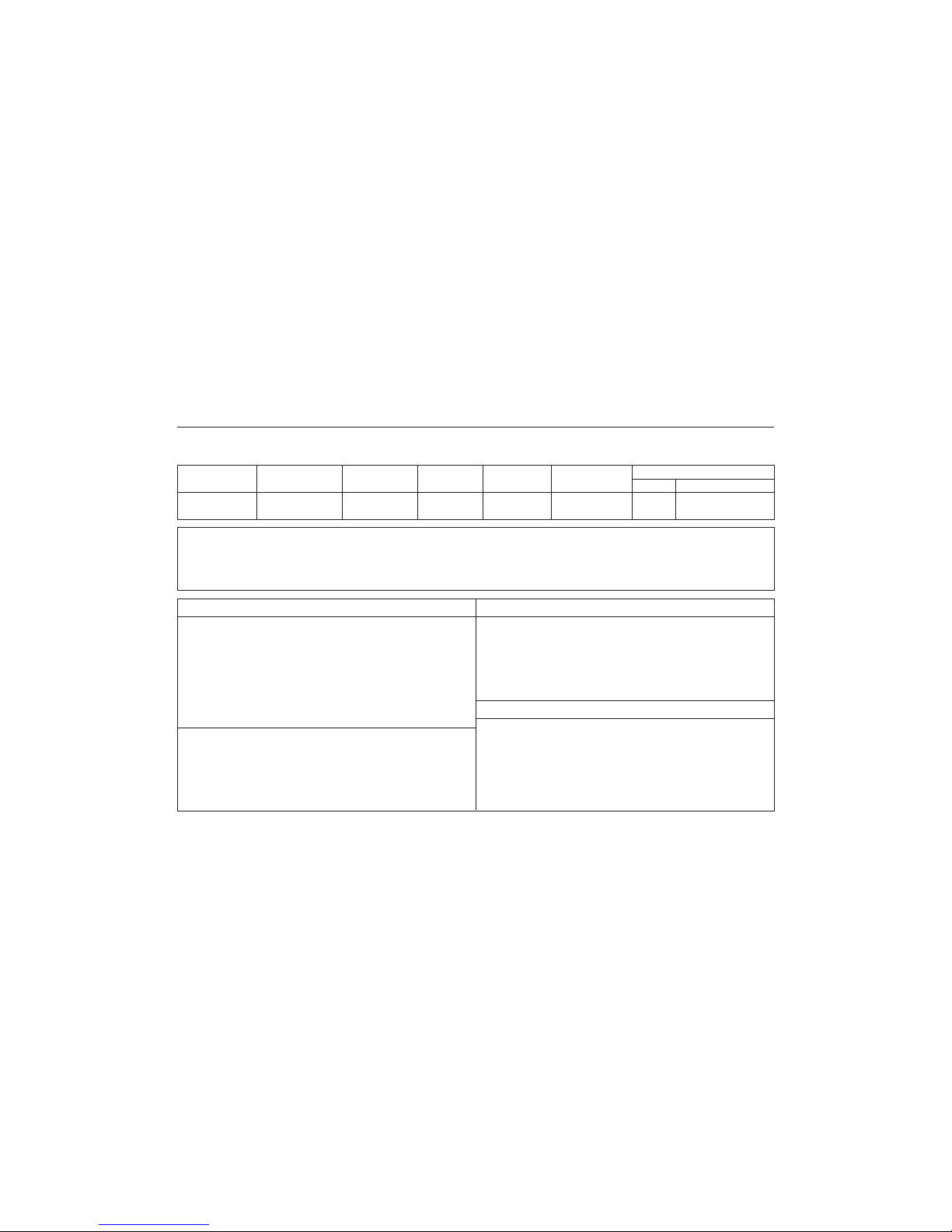
MODEL CHASSIS NO. ENGINE NO. KEY NO. DATE OF ODOMETER BATTERY
DELIVERY READING (KM)
MAKE SR. NO./BATCH CODE
OWNER’S NAME & ADDRESS ____________________________________________________________________________
_____________________________________________________________________ TEL. NO. _________________________
ADDRESS/STAMP OF SELLING DEALER SELLING DEALER CODE
SHOWROOM
WORKSHOP
VEHICLE DETAILS
Page 5

5
83K
F....free Service P....Paid Service W....Warranty. A....Accident
DATE OF KIND OF MILEAGE DESCRIPTION OF JOB NAME OF SERVICING JOB CARD MECHANIC’S
SERVICE SERVICE (km) DEALER/MASS NO. SIGNATURE
1-2
MAINTENANCE SERVICE RECORD
Page 6

6
83K
WARRANTY POLICY
2-1
WARRANTY POLICY
Maruti Suzuki India Limited (hereinafter called "Maruti Suzuki"),
warrants that each new Maruti Suzuki vehicle distributed in India
by Maruti Suzuki and sold by an authorised Maruti Suzuki dealer
will be free, under normal use and service, from any defects in
material and workmanship at the time of manufacture SUBJECT
TO THE FOLLOWING TERMS AND CONDITIONS:
(1) Qualification:
To qualify for this warranty:
(a) The Maruti Suzuki vehicle must be delivered by Maruti
Suzuki authorised dealer and set-up, serviced by Maruti
Suzuki authorised dealer/service station.
(b) The warranty registration card in respect of each vehicle
must be completed by the dealer at the time of delivery
of the vehicle and dealer should retain the same.
(2) Term:
The term of the warranty shall be twenty four (24) months
or 40,000 kilometers (whichever occurs first) from the date
of delivery to the first owner.
(3) Maruti Suzuki's Warranty Obligation:
If any defect(s) should be found in a Maruti Suzuki vehicle
within the term stipulated above, Maruti Suzuki's only obligation
is to repair or replace at its sole discretion any part shown
to be defec-tive, with a new part or the equivalent at no cost
to the owner for parts or labour, when Maruti Suzuki
acknowledges that such a defect is attributable to faulty
material or workmanship at the time of manufacture. The
owner is responsible for any repair or replacements which are
not covered by this warranty.
(4) Limitation:
This warranty shall not apply to:
(1) Normal maintenance service required other than the three
free services, including without limitation, oil and fluid
changes, headlight aiming, fastener retightening, wheel balancing, wheel alignment and tyre rotation, cleaning of injectors, adjustments of carburettor, ignition timing, clutch and
valve clearance.
(2) The replacement of normal wear parts including without
limitation, bulbs, tyres and tubes, spark plugs, belts, hoses,
filters, wiper blades, brushes, contact points, fuses, clutch
disc, brake shoes, brake pads, cable and all rubber parts
(except oil seal and glass run).
(3) Any vehicle which has been used for competition or racing.
(4) Any repairs or replacement required as a result of
accidents or collision.
(5) Any defects caused by misuse, negligence, abnormal use
or insufficient care.
(6) Any vehicle which has been modified or altered, including
without limitation, the installation of performance accessories.
(7) Any vehicle on which parts or accessories not approved
by Maruti Suzuki have been used.
(8) Any vehicle which has not been operated in accordance
with the operating instructions in the Maruti Suzuki Owner’s
Manual.
(9) Any vehicle which has not received, during the warranty
term, the service inspections prescribed in the Maruti
Suzuki Owner’s Manual.
(10) Any vehicle which has been assembled, disassembled,
adjusted or repaired by other than an Maruti Suzuki
authorised dealer/service station.
Page 7

7
83K
WARRANTY POLICY
2-2
(11) Any vehicle which has been used for purposes other than
what it was designed for.
(12) Any damage or deterioration caused by industrial pollution
and bird droppings.
(13) Insignificant defects which do not affect the function of
the vehicle including without limitation, sound, vibration
and fluid seep.
(14) Any natural wear and tear including without limitation,
aging etc.
(15) Installation and usage of Domestic LPG Gas/LPG cylinder.
(16) V-belts, hoses and gas leaks (For Maruti Suzuki AC
vehicle).
(17) Any vehicle retrofitted with LPG / CNG kits.
(5) Extent of Warranty:
This warranty is the entire written warranty given by Maruti
Suzuki for Maruti Suzuki vehicles and no dealer or its or his
agent or employee is authorised to extend or enlarge this
warranty and no dealer or its or his agent or employee is
authorised to make any oral warranty on Maruti Suzuki's
behalf.
Maruti Suzuki reserves the right to add any improvements or
change the design of any model at any time with no obligation
to make the same changes on units previously sold.
(6) Warranty Service:
To obtain warranty service, the complete vehicle must be
presented at the owner’s expenses to any authorised Maruti
Suzuki dealer.
(7) Owner’s Warranty Responsibilities:
It is responsibility of each owner to:
(a) Make certain that the warranty registration/PDI card was
completed at the time of delivery of the vehicle;
(b) Have performed, at his own expenses, by an Maruti
Suzuki authorised dealer/service station all the service
inspections specified in the Maruti Suzuki “Owner’s Manual
and Service Booklet” and maintain adequate proof that
such service inspections have been performed.
(c) make certain that the Maruti Suzuki authorised dealer/
servise station performing the service inspection has
certified the work on the “Maintenance Service Record”
page in the “Owner’s Manual and Service Booklet” and
(d) Present the Maruti Suzuki “Owner’s Manual and Service
Booklet” to the authorised Maruti Suzuki dealer whenever
requesting service inspections or warranty service.
If the “Owner’s Manual and Service Booklet” should be lost
or destroyed the owner should consult the authorised Maruti
Suzuki dealer from whom the vehicle was purchased for
instructions concerning replacement of the “Owner’s Manual
and Service Booklet”.
(8) Disclaimer of Consequential Damage:
Maruti Suzuki assumes no responsibility for loss of vehicle,
loss of time, inconvenience or any other indirect incidental
or consequential damage resulting from the vehicle not being
available to the owner because of any defect covered by this
warranty.
(9) Change of Owner
Even if ownership of the vehicle changes, the remaining
warranty period is effective for the new owner.
Page 8

8
83K
Maruti Suzuki offers the Emission Warranty on all Maruti Suzuki vehicles (apart from the Regular warranty and will run parallel
to the regular product warranty) only in four metropolitan cities (New Delhi, Kolkata, Mumbai and Chennai) with effect from
July 1st, 2001.
Terms:
The Emission Warranty will be applicable for 80,000 kms or 3 years (Which ever comes earlier) from the date of delivery to
the first owner. The remaining warranty terms will be valid in case of any change in ownership provided the production of all
valid document.
Conditions:
1. Under Emission Warranty, Warranty claims will be admitted for a prima facie examination, in case vehicle fails to meet to the
Emission Standard as specified in sub rule (2) of rule no. 115 of Central Motor Vehicles Rules (CMVR), 1989.
2. The warranty claims will only be accepted after examination carried out by Maruti Suzuki or it's dealer which leads to firm conclusions
that the
a) Original settings have not been tempered in any case.
b) Part (as given in Annexure-A) has a manufacturing defect.
c) Vehicle is unable to meet the Emission Standards (as given in 1.), inspite of the vehicle having been maintained and used
in accordance with the instructions as specified in Owner's Manual and Service Booklet and the used fuel and different oils
(Engine oil, Transmission oil, Brake oil etc.) are also as per specification.
3. The method of examination for deciding the warranty of the parts will be at the sole discretion of Maruti Suzuki and it's dealer
and results of the examination will be final and binding. If after examination, the warrantable condition is not established, Maruti
Suzuki and it's dealer has the right to charge all, or part of the cost of such examination.
4. Under Emission Warranty, the parts (as given in Annexure-A) will be changed free of cost, but the consumables will be charged
as per actual.
5. If the part covered under Emission Warranty or the associated parts, are not independently replaceable, on account of these being
integral parts a complete assembly, Maruti Suzuki and it's dealer will have the sole discretion to replace entire assembly or by
using some of the parts of the system through suitable repair or modifications.
EMISSION WARRANTY
2-3
EMISSION WARRANTY
Page 9

9
83K
6. Any consequential repairs or replacement of parts which may be found necessary to establish compliance of Emission Warranty,
will not be considered under warranty, unless the same is under product warranty. The consumable will be charged as per actual
under such repair or replacement.
7. Maruti Suzuki will not be responsible for the cost of transportation of the vehicle to the nearest Maruti Suzuki dealer workshop
or any loss due to non-availability of the vehicle during the period of lodging of a warranty claim and examination and/or repair
by Maruti Suzuki dealer.
8. Maruti Suzuki will not be responsible for any penalty that may be charged by statutory authorities on account of failure to comply
with the EMISSION STANDARDS.
9. Emission Warranty will not be affected on the change of owner, provided all the documents are available.
10. All maintenance actions (as specified in the Owner's Manual and Service Booklet) need to be followed and recorded in the manual
for emission warranty.
11. The customer needs to produce the PUC (Pollution Under Control) certificate valid for the period preceding the test during which
the failure is discovered. The receipts (for the maintenance of the vehicle as per specification in Owner's Manual and Service
Booklet from the date of original purchase of the vehicle) will also be required.
Condition Under which the Emission Warranty is not APPLICABLE
1. In the absence of valid PUC certificate.
2. Vehicle not serviced from Maruti Suzuki authorised workshop as per the schedule specified in the Owner's Manual.
3. Vehicle subjected to abnormal use (accident, motor race, rallies or for the purpose of establishing the records etc.)
4. Use of non MGP (Maruti Genuine Part).
5. Vehicle tempered in an unauthorised manner.
6. Tampering with odometer so that the actual kilometer reading can not be read.
7. Use of adulterated fuel and/or unspecified oils (Engine oil, Transmission oil and Brake oil etc.)
EMISSION WARRANTY
2-4
Page 10

10
83K
Annexure-A
List of parts covered under Emission Warranty
1. Fuel injection Assembly, Pressure Regulator, Throttle Body Assembly.
2. Electronic Control Module (ECM).
3. Intake Manifold.
4. EGR valve.
5. Distributor and internal parts.
6. Ignitions coil.
7. Canister Assembly.
8. Vapour Liquid Separator.
9. Fuel Tank and Filler Cap.
10. PCV (Positive Crankcase Ventilation) Valve.
11. Oil Filler Cap.
12. Catalytic Convertor.
13. Exhaust manifold.
14. All fuel injection System related SENSORS.
15. High Pressure Fuel Pump.
16. Glow Plug.
17. Glow Plug Controller.
18. Maniverter
EMISSION WARRANTY
2-5
Page 11

11
83K
FUEL RECOMMENDATION
FUEL RECOMMENDATION
Petrol Engine
You must use unleaded petrol with an
octane number (RON) of 91 or higher.
Diesel Engine
The diesel fuel should be with cetane number (CN) higher than 51 and sulphur content less than 350 ppm (parts per million).
Do not use marine diesel fuel, heating oils
and so forth.
Petrol/Ethanol blends
Blends of unleaded petrol and ethanol (grain
alcohol), also known as gasohol, are
commercially available in some areas.
Blends of this type may be used in your
vehicle if they are no more than 10% ethanol. Make sure this petrol-ethanol blend has
octane ratings no lower than those
recommended for petrol.
Petrol/Methanol blends
Blends of unleaded petrol and methanol
(wood alcohol) are also commercially available in some areas. DO NOT USE fuels
containing more than 5% methanol under any
circumstances. Fuel system damage or
vehicle performance problems resulting from
the use of such fuels are not the
responsibility of MARUTI SUZUKI and may
not be covered under the New Vehicle
Warranty.
Fuels containing 5% or less methanol may
be suitable for use in your vehicle if they
contain cosolvents and corrosion inhibitors.
NOTE:
If you are not satisfied with the driveability
or fuel economy of your vehicle when you
are using a petrol/alcohol blend, you should
switch back to unleaded petrol containing no
alcohol.
The fuel tank has an air space to
allow for fuel expansion in hot
weather. If you continue to add fuel
after the filler nozzle has automatically
shut off or an initial blowback occurs,
the air chamber will become full.
Exposure to heat when fully fuelled in
this manner will result in leakage due
to fuel expansion. To prevent such
fuel leakage, stop filling after the filler
nozzle has automatically shut off, or
when using an alternative non
automatic system, initial vent
blowback occurs.
CAUTION
CAUTION
Be careful not to spill fuel containing
alcohol while refueling. If fuel is
spilled on the vehicle body, wipe it up
immediately. Fuels containing alcohol
can cause paint damage, which is not
covered under the New Vehicle
Limited Warranty.
3-1
Page 12

12
83K
BEFORE DRIVING
Keys ...................................................................................................................................... 4-1
Door Locks .......................................................................................................................... 4-2
Keyless Entry System Transmitter (if equipped) ......................................................... 4-4
Mirrors ................................................................................................................................ 4-13
Heated Rear Window Switch (if equipped) ................................................................. 4-14
Front Seats ........................................................................................................................ 4-14
Rear Seats ......................................................................................................................... 4-16
Seat Belts and Child Restraint Systems ..................................................................... 4-18
Supplemental Restraint System (air bags) (if equipped) ......................................... 4-24
Instrument Cluster (For Petrol & Diesel) .................................................................... 4-28
Warning and Indicator Lights ........................................................................................ 4-29
Speedometer/Odometer/Trip meter/Meter Illumination Control ................................ 4-34
Tachometer (if equipped) ................................................................................................ 4-35
Fuel Gauge ........................................................................................................................ 4-35
Lighting Control Lever .................................................................................................... 4-38
Front Fog Light Switch (if equipped) .......................................................................... 4-39
Rear Fog Light Switch (if equipped) ............................................................................ 4-39
Headlight Leveling Switch .............................................................................................. 4-39
Turn Signal Control Lever .............................................................................................. 4-40
Hazard Warning Switch ................................................................................................... 4-40
Windshield Wiper and Washer Lever ........................................................................... 4-40
Rear Window Wiper/Washer Switch (if equipped) ..................................................... 4-41
Tilt Steering Lock Lever (if equipped) ......................................................................... 4-42
Horn ..................................................................................................................................... 4-42
BEFORE DRIVING
Page 13

13
83K
In case of attaching any metal objects
to the immobilizer key, it may not
start the engine.
The immobilizer key is a sensitive
electronic instrument. To avoid damaging the immobilizer key:
• Do not expose it to impacts, moisture or high temperature such as by
leaving it on the dashboard under
direct sunlight.
• Keep the immobilizer key away from
magnetic objects.
Keys
which has an electronic identification code
programmed into it. The key communicates
the identification code to the vehicle when
the key is turned to the “ON” position. If you
need to make spare keys, visit (contact)
your MARUTI SUZUKI authorized dealer.
The vehicle must be programmed with the
correct identification code for the spare
keys. A key made by an ordinary locksmith
will not work.
Your vehicle comes with a pair of identical
keys. Keep the spare key in a safe place.
One key can open all of the locks on the
vehicle.
The key identification number is stamped on
a metal tag provided with the keys or on
the keys. Keep the tag (if equipped) in a
safe place. If you lose your keys, you will
need this number to have new keys made.
Write the number below for your future reference.
KEY NUMBER
If the immobilizer system light (1) for petrol
engine or service vehicle soon (SVS) light
(2) for diesel engine blinks when the ignition switch is in the “ON” position, there
may be something wrong with your key or
with the immobilizer system. Contact your
MARUTI SUZUKI authorized dealer to
inspect the system.
NOTE:
• If you lose your immobilizer ignition key,
contact your MARUTI SUZUKI dealer as
soon as possible to have the lost one
deactivated, then have the new key
made by them.
• If you own other vehicles with immobilizer keys, keep those keys away from
the ignition switch when using your vehicle, or the engine may not be started
because they may interfere with your
vehicle’s immobilizer system.
CAUTION
EXAMPLE
BEFORE DRIVING
4-1
83K-02-001
Immobilizer System
This system is designed to help prevent
vehicle theft by electronically disabling the
engine starting system.
The engine can be started only with your
vehicle’s original immobilizer ignition key
83K-02-002
Ignition Key Reminder (if equipped)
A buzzer sounds intermittently to remind
you to remove the ignition key if it is in the
ignition switch when the driver’s door is
opened.
Page 14
14
83K
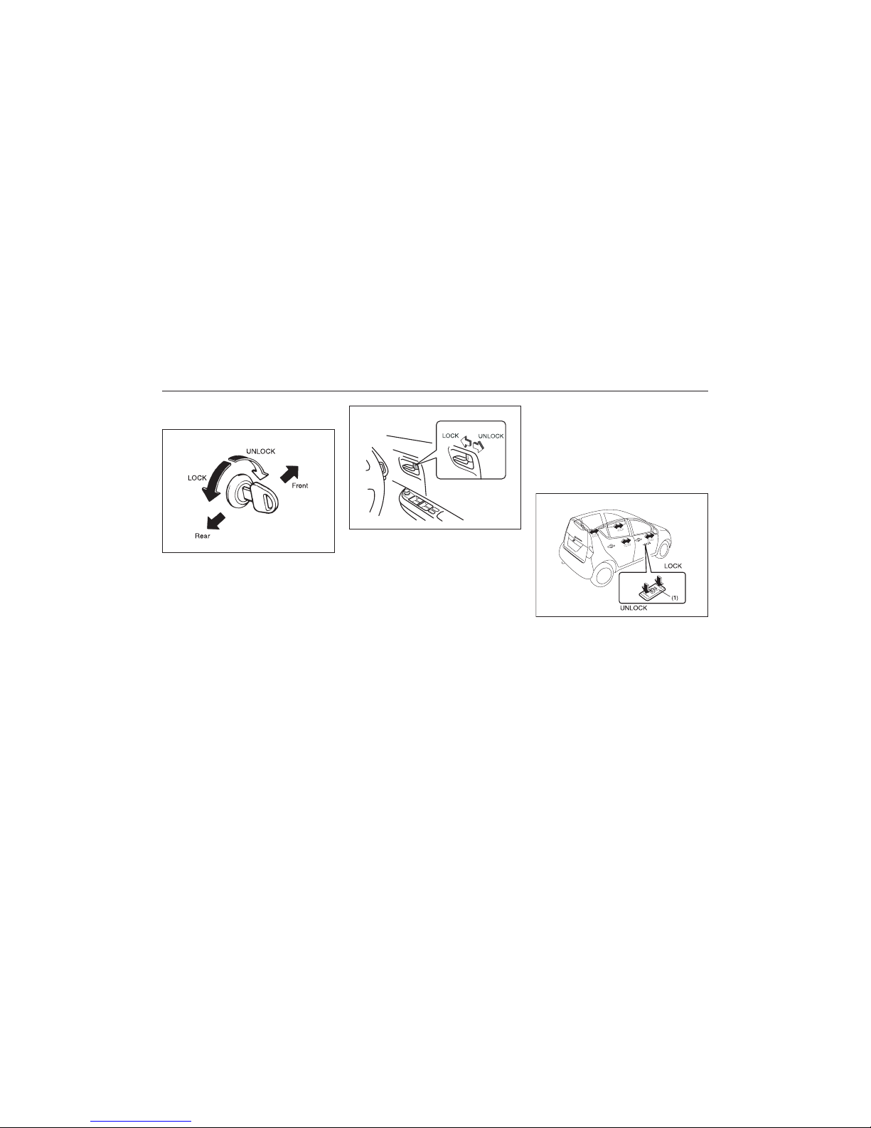
Door Locks
Side Door Locks
To lock a door from inside the vehicle, turn
the lock knob forward. Turn the lock knob
backward to unlock the door.
NOTE:
Be sure to hold the door handle up when
you close a locked front door, as the door
will not remain locked.
EXAMPLE
BEFORE DRIVING
4-2
83K-02-003
To lock a front door from outside the vehicle:
• Insert the key and turn the top of the
key anti clockwise or
• Turn the lock knob forward and hold the
door handle as you close the door.
To unlock a front door from outside the
vehicle, insert the key and turn the top of
the key clockwise.
To lock a door from outside the vehicle, turn
the lock knob forward and close the door.
83K-02-004
Central Door Locking System
Driver’s door (if equipped)
You can lock and unlock all doors (including the tailgate) simultaneously by using the
key in the driver’s door lock.
To lock all doors simultaneously, insert the
key in the driver’s door lock and turn the
top of the key anti-clockwise
To unlock all doors simultaneously, insert
the key in a driver’s door lock and turn the
top of the key toward the front of the vehicle twice.
To unlock the driver’s door only, insert the
key in that door lock and turn the top of
the key toward the front of the vehicle once.
You can also lock or unlock (4 or 5) all
doors by depressing the front or rear of the
switch (1), respectively.
NOTE:
If your vehicle is equipped with keyless
entry system, you can also lock or unlock
all doors by operating the transmitter. Refer
to “Keyless Entry System Transmitter”.
83K-02-006
EXAMPLE
Page 15
15
83K
NOTE:
Individual doors can also be UNLOCKED
anytime by using their respective "Door
Lock Knob" inside the vehicle.
If child proof locks are in locked position,
rear doors cannot be opened from inside.
ww
ww
w WARNING
Be sure to place the child-proof lock
in the locked position whenever children are seated in the rear.
BEFORE DRIVING
4-3
Child-Proof Locks (rear side door)
83K-02-007
EXAMPLE
As illustrated, a child-proof lock is provided
for both rear doors. When the lock lever is
in position (1), the child-proof lock is locked,
and when in position (2), the child-proof lock
is unlocked. When the child-proof lock is in
the locked position, the rear door cannot be
opened from the inside even if the inside
door lock is unlocked but can be opened
from the outside.
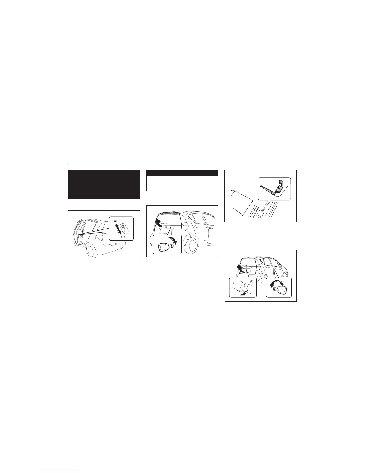
Manual tailgate unlatch
Type1 (if equipped)
83K-02-008
EXAMPLE
To open the tailgate, insert the key and turn
it clockwise to unlatch and lift the tailgate.
You can also unlatch the tailgate-trunk lid by
pulling the release lever (if equipped) located
on the outboard side of the driver’s seat.
Type2 (if equipped)
83K-02-009
83K-02-010
EXAMPLE
EXAMPLE
(1) Tailgate handle
Page 16
16
83K
You can lock and unlock the tailgate by
using the key in the driver’s door lock.
To open the tailgate, pull up and hold the
tailgate unlatch handle (1) and lift the tailgate.
ww
ww
w WARNING
Always make sure that the tailgate is
closed and latched securely. Completely closing the tailgate helps prevent occupants from being thrown
from the vehicle in the event of an
accident. Completely closing it also
helps keep away exhaust gases from
entering the car.
BEFORE DRIVING
4-4
83K-02-011
2) Push open the tailgate from inside by
pushing up on the emergency lever (2)
using a flat blade screw driver or the
jack handle. The tailgate will be latched
again by closing the tailgate simply.
If the tailgate can not be unlatched by pulling up the tailgate unlatch switch (1), have
the vehicle inspected by your MARUTI
SUZUKI authorized dealer.
If you can not unlatch the tailgate by pulling
up the unlatch handle (1) due to a malfunction, follow the procedures below to unlatch
the tailgate from inside the vehicle.
1) Fold the rear seat forward for easier
access. Refer to “Folding Rear Seats”
section for details on how to fold the
rear seat forward.
ww
ww
w WARNING
• To avoid injury, do not use your finger to push the emergency lever.
• Make sure there is no one near the
tailgate when pushing open the tailgate from inside the vehicle.
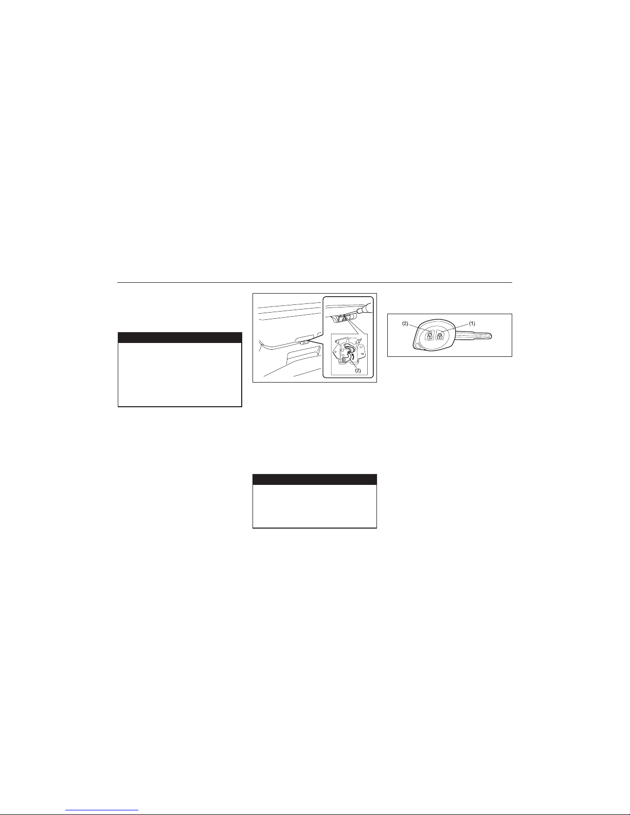
Keyless Entry System Transmitter (if equipped)
83K-02-012
(1) “LOCK” button
(2) “UNLOCK” button
There are two ways to lock or unlock all
doors (including the tailgate) simultaneously
by operating the transmitter near the vehicle.
Central door locking system
• To lock all doors, push the “LOCK” button (1) once.
• To unlock all other doors, push the
“UNLOCK” button (2) once.
The turn signal lights will flash once when
the doors are locked.
When the doors are unlocked:
• The turn signal lights will flash twice.
• If the interior light switch is in the middle
position, the interior light will turn on for
about 15 seconds and then fade out. If
you insert the key into the ignition switch
during this time, the light will start to
fade out immediately.
Page 17
17
83K
BEFORE DRIVING
4-5
Be sure the doors are locked after you
operate the “LOCK” button. If no door is
opened within about 30 seconds after the
“UNLOCK” button is operated, the doors will
automatically lock again.
NOTE:
• The maximum operating distance of the
keyless entry system transmitter is about
5 m (16 ft.), but this can vary depending
on the surroundings, especially near
other transmitting devices such as radio
towers or CB (citizen’s band).
• The door locks can not be operated with
the transmitter if the ignition switch is in
a position other than “LOCK”, or the ignition key is inserted in the ignition switch.
• When any door is open, the door locks
can be operated only unlock with the
transmitter, and the turn signal light will
not flash.
• If you lose one of the transmitters, contact your MARUTI SUZUKI authorized
dealer as soon as possible for a replacement. Be sure to have your dealer program the new transmitter code in your
vehicle’s memory so that the old code
is erased.
CAUTION
The transmitter is a sensitive electronic instrument. To avoid damaging
the transmitter:
• Do not expose it to impacts, moisture or high temperature such as by
leaving it on the dashboard under
direct sunlight.
• Keep the transmitter away from
magnetic objects such as a television.
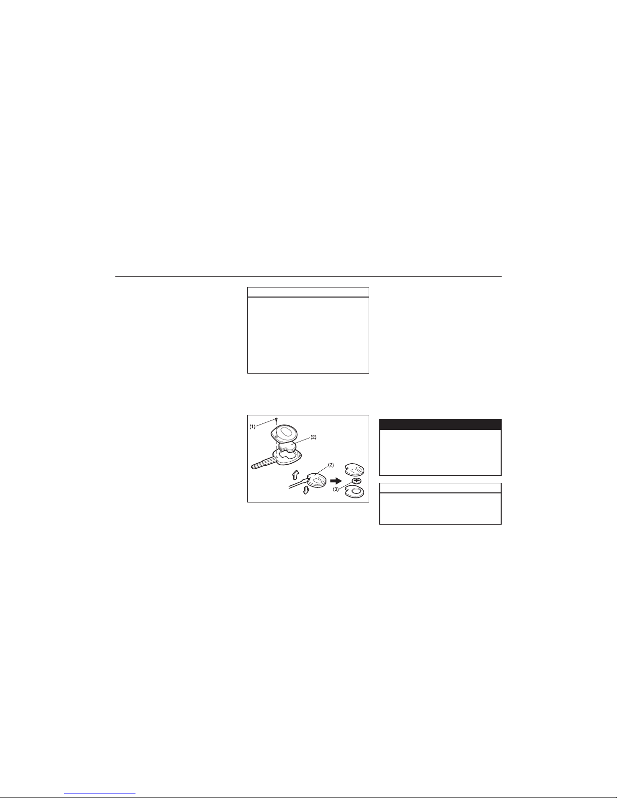
Replacement of the Battery
If the transmitter gets discharged, replace
the battery with a new one.
To replace the battery of the transmitter:
83K-02-013
1) Remove the screw (1), and open the
transmitter cover.
2) Remove the transmitter (2).
3) Put the edge of a flat blade screw driver
in the slot of the transmitter (2) and pry
it open.
4) Replace the battery (3) (Lithium disc-type
CR1620 or equivalent) so its + terminal
faces the “+” mark of the transmitter.
5) Close the transmitter and install it into
the transmitter holder.
6) Close the transmitter cover, install and
tighten the screw (1).
7) Make sure the door locks can be operated with the transmitter.
8) Dispose of the used battery properly
according to applicable rules or regulations. Do not dispose of lithium batteries with ordinary household trash.
CAUTION
ww
ww
w WARNING
Swallowing a lithium battery may
cause serious internal injury. Do not
allow anyone to swallow a lithium
battery. Keep lithium batteries away
from children and pets. If swallowed,
contact a physician immediately.
The transmitter is a sensitive electronic instrument. To avoid damaging
it, do not expose it to dust or moisture or tamper with internal parts.
Page 18
18
83K
BEFORE DRIVING
4-6
Keyless Entry Cum Alarm
System (if equipped)
System
83K-02-015
The Keyless Entry Cum Alarm System has
two basic modes of operation.
VALET MODE
When the vehicle is to be given for servicing or Valet parking, turn the system into
Valet mode. In Valet mode all the Security
features of system will be OFF. The System will work as a Keyless Entry/Exit in this
mode.
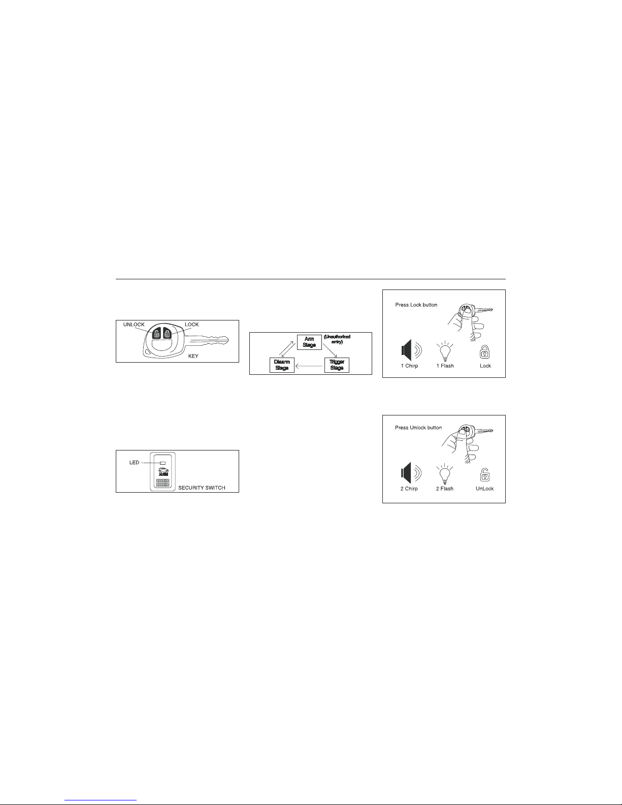
83K-02-016
designed to protect your vehicle from
unauthorized entry. The system can be
operated in three stages. The First is “Arm
Stage” , Second is “ Trigger Stage” & Third
is “Disarm Stage”.
ALARM MODE
Alarm mode system is in three stages: Arm,
Disarm & Trigger stage. The system is
83K-02-017
83K-02-018
ARM STAGE
In Arm Stage, your vehicle is safe from any
unauthorized entry.
1) Press and release the Key Lock button.
2) One Siren chirp and one indicator light
flash will confirm Arm and Lock.
3) Doors will get locked and vehicle will get
armed.
4) Visible theft warning LED on security
switch will flash slowly.
NOTE: System will not Arm in following
condition:
1. If any of door is open (except Bonnet).
2. If System is in Valet Mode.
3. If Key is in key cylinder.
TRIGGER STAGE
If anybody tries to tamper with the vehicle,
the alarm triggers and indicators flashes
DISARM STAGE
System should be brought in Disarm Mode
83K-02-019
Page 19
19
83K
BEFORE DRIVING
4-7
while you are entering/exiting the vehicle.
a) Press and release the Key Unlock but-
ton.
b) Two Siren chrip and two indicator light-
flashes will confirm Disarm and Unlock.
c) Doors will get Unlock and vehicle will get
disarmed.
d) Visible theft warning LED on security
switch will flash fastly.
83K-02-020
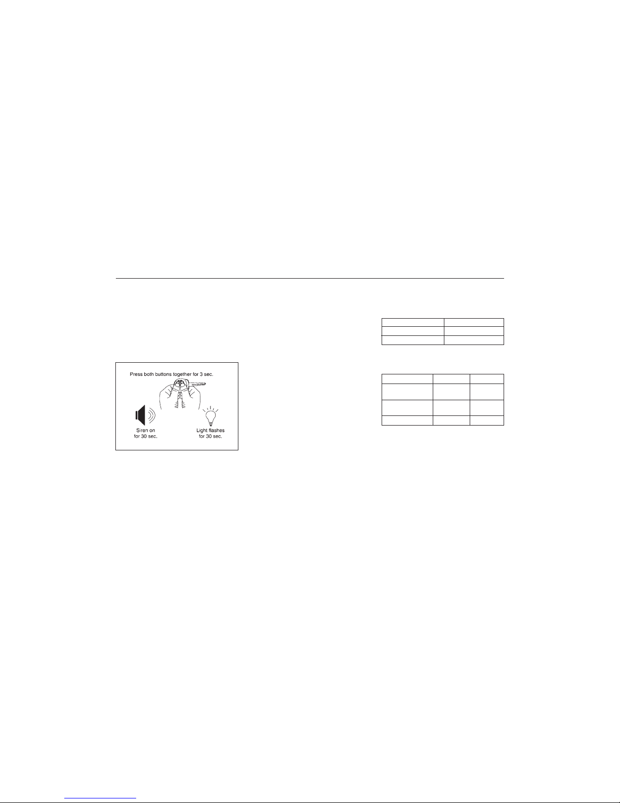
Panic Alarm (Car Locator)
Panic Alarm is designed to bring attention
to the vehicle and to locate the vehicle in
congested packed parking area.
a) Press and hold the Key Lock & Unlock-
button simultaneously for 3 seconds.
b) Panic alarm will be activated and siren
will sound and indicator lights will flash
for 30 seconds.
c) Press and release the Key Lock &
Unlock button simultaneously within 30
seconds to cancel the Panic alarm.
General Feature
Mute Lock/Unlock
To Arm/Disram the vehicle without siren
chirps use this function.
a) Press and release the Key Lock &
Unlock buttons simultaneously.
b) Press and release Key Lock or Unlock
button for desired function.
Example: To Lock the system without the
Siren chirp sound, press and release the Key
Lock & Unlock button simultaneously, then
press and release the Key Lock button.
Auto Rearm
In case of accidental Unlock/Disarm of
vehicle by Key, vehicle will automatically
Lock & Arm within 30 sec. without any indication, if no door is opened in this 30 sec.
NOTE : If the vehicle is in Valet Mode system will only Lock the vehicle.
Radio Frequency Lock Out
Key Lock/Unlock/Panic will ceases to function when Key is present in Key cylinder.
Flashing LED Status
The flashing LED always reflects the status
of the system as following.
SYSTEM CONDITION LED STATUS
Disarmed condition LED does not glow
Armed condition Slow Flashes of LED
Diagnostic report Visual-LED Sound
Built in shock 2 Flashes Four Chirps
sensor Triggered
Door / Trunk 3 Flashes Four Chirps
Instrusion
Ignition 5 Flashes Four Chirps
Intrusion Alert
The system gives a report if it has been
tampered in your absence.
Programmable Features
System have some feature which can be
programmed by user according to their
choice.
Drive Lock Mode
Drive lock mode can be programmed by
SPEED or can be turn OFF. In case of
drive lock mode is programmed to SPEED
LOCK, all the vehicle doors will lock when
vehicle attains the speed of 20 Km/hr. If
Drive Lock is programmed to OFF, no door
will lock by speed.
Page 20

20
83K
BEFORE DRIVING
4-8
NOTE: In case of Speed Lock feature, open
& close of Door while driving will cause
cancellation of Speed Lock.
Drive Unlock Mode
Drive unlock can be programmed by KEY
or can be turn OFF. When programmed to
KEY, turning IGN ON-OFF, then removing
the key from the key cylinder will unlock all
the doors. In case if drive unlock is programmed to OFF then no door will unlock
by removing key from key cylinder.
Siren Chirp ON/OFF feature
Siren Chirps are produced whenever System is Arm/Disarm by key. When siren chirp
feature disabled, siren will not chirp after
Arm/Disarm by Key.
Shock Sensor feature
This is a very important feature of security
system, It enables protection of your vehcle against any major impact. If anybody
tries to tamper with the vehicle, the alarm
triggers. The triggering of the alarm is in
two stages, first acting as a warning to the
intruder and then at full blast. The sensitivity
of impact sensor can be adjusted as desired
by the user.
Programming Drive Lock Mode
a) Open the Driver Door of your vehicle.
b) With your vehicle key in the key cylinder,
turn IGN ON and then switch it OFF.
c) Press and release the Security switch
One time.
d) Press and hold the Security switch.
e) One chirp sound confirms entry into
Drive Lock programming mode.
f) Press the Key Lock button (while holding
the Security switch), a single chirp sound
confirms mode changed to speed lock.
g) Two-Siren chirp sound confirms Drive
lock mode OFF.
h) Release the Security switch.
i) Turn the IGN ON.
Programming Drive Unlock Mode
a) Open the Driver Door of your vehicle.
b) With your vehicle key in the key cylinder,
turn IGN ON and then switch it OFF.
c) Press and release the Security switch
two times.
d) Press and hold the Security switch.
e) Two-chirp sound confirms entry into
Drive unlock programming mode.
f) Press the Key Lock button (while hold-
ing the Security switch), a single chirp
sound confirms the mode changed to
key Unlock.
g) Two-siren chirp sound confirms the
mode changed to Drive Unlock mode
OFF.
h) Release the Security switch.
i) Turn the IGN ON.
Programming Siren Chirp ON/OFF
a) Open the Driver Door of your vehicle.
b) With your vehicle key in the key cylinder,
turn IGN ON and then switch it OFF.
c) Press and release the Security switch
Three times.
d) Press and hold the Security switch.
e) Three-chirp sound confirms entry into
Siren Chirp ON/OFF programming mode.
f) Press the Key Lock button (while hold-
ing the Security switch), a single sound
confirms the mode changed to Siren
Chirp ON.
g) Two-Siren chirp sound confirms the
mode changed to Siren Chirp OFF.
h) Release the Security switch.
i) Turn the IGN ON.
Procedure To Program Feature
Feature 1 Chirp 2 Chirps Default
1. Drive Lock
Mode Speed OFF Speed
2. Drive Unlock
Mode Key OFF Key
3. Siren chirp
ON/OFF ON OFF ON
4. Shock Sensor
ON/OFF ON OFF ON
Page 21

21
83K
BEFORE DRIVING
4-9
Programming Shock Sensor ON/OFF
a) Open the Driver Door of your vehicle.
b) With your vehicle key in the key cylin-
der, turn IGN ON and then switch it
OFF.
c) Press and release the Security switch
Four times.
d) Press and hold the Security switch.
e) Four-chirp sound confirms entry into
Shock Sensor ON/OFF programming
mode.
f) Press the Key Lock button (while hold-
ing the Security switch), a single chirp
sound confirms the mode changed to
shock sensor ON.
g) Two-Siren chirp sound confirms the
mode changed to shock sensor OFF.
h) Release the Security switch.
i) Turn the IGN ON.
Shock Sensor Sensitivity
Adjustment via Key
Full Blast Adjustment
Full Blast can be adjustment in 16 levels
as mentioned below.
a) Press Unlock button on Key to Unlock/
Disarm the System.
b) Press Lock button on Key to Lock/Arm
the System.
c) Within 5 sec press Lock & Unlock but-
ton simultaneously for at least 2 sec.
Siren will give long chirp to confirm entry
into sensitivity adjustment mode
i) Press Key Lock button to adjust the
sensitivity one step lower. Siren will
give one chirp every time lock button
is pressed till at level 0 where it will
give a long chirp. When adjust to level
0, Full Blast will turn OFF
ii) Press Key unlock button to adjust the
sensitivity one step higher. Siren will
give two chirp every time unlock
button is pressed till at level 16 where
it will give a long chirp.
Pre-warn Adjustment
Pre-warn can be adjusted in 16 levels as
mentioned below:
a) Press Lock button on Key to Lock/Arm
the System
b) Press Unlock button on Key to Unlock/
Disarm the System
c) Within 5 sec press Lock & Unlock but-
ton simultaneously for at least 2 sec.
Siren will give Long chirp to confirm
entry into Sensitivity Adjustment Mode.
i) Press Key Lock button to adjust the
sensitivity one step lower. Siren will
give one chirp every time lock button
is pressed till at level 0 where it will
give a long chirp. When adjusts to
level 0, prewarn will turn OFF.
ii) Press Key Unlock button to adjust the
sensitivity one step higher. Siren will
give two Chirp every time Unlock
button is pressed till at level 16 where
it will give a long chirp.
Programming of Valet Mode
This feature can be programmed as follows:
i) Close the driver door.
ii) Turn IGN ON-OFF quickly.
iii) Press and hold Security switch for 3 sec
minimum, LED will turn ON for 1 minute.
Repeat step 1-3 to come out of Valet Mode,
1 Siren chirp sound will indicate Valet Mode
OFF.
Program Customer Pincode
(Personalised Pincode)
The Personalised 4-digit number can be
changed from the factory default to ensure
Personalised Security.
Pin code entry
a) Disarm the system.
b) Open the Driver Door.
c) Turn IGN ON then OFF.
d) Within 5 seconds press and release
Valet switch 5 times. A short chirp followed by long chirps confirms entry into
Pin Code programming mode.
Page 22

22
83K
BEFORE DRIVING
4-10
e) Press Lock button on Key, after a sin-
gle chirp enter the First digit (with in 1-
9) by pressing Valet switch (for e.g. to
enter 2 press and release Valet switch
two times).
f) Press Lock button on Key, after two
chirp enter the Second digit (with in 1-
9) by pressing Valet switch.
g) Press Lock button on Key, after 3-chirps
enter the Third digit (with in 1-9) by
Pressing Valet switch.
h) Press Lock button on Key, after 4-chirps
enter the Fourth digit (with in 1-9) by
pressing Valet switch.
Emergency Disarm by personalised pin
code
The Personalised 4- Digit Pin Code acts as
a secret Key, to Emergency Disarm the
vehicle.
a) Turn the IGN ON, OFF and then ON.
b) Enter the First digit (for e. g. to enter 2
press and release Valet switch twice)
c) Turn the IGN OFF then ON.
d) Enter the Second digit.
e) Turn the IGN OFF and then ON.
f) Enter the Third Digit.
g) Turn the IGN OFF and then ON
h) Enter the Last Digit.
i) Turn the IGN OFF and then ON.
The vehicle will get disarmed.
Page 23

23
83K
BEFORE DRIVING
4-11
SYMPTOMS
Transmitter can't activate or deactivate the
center lock system or alarm
Control distance of the transmitter becomes
nearer (less than 10m)
It is difficult to activate or deactivate the
system in certain area using the transmitter.
Open door(s), front bonnet not trigger the
alarm.
Siren does not sound when alarm is
triggered.
Troubleshooting
PROBABLE CAUSES
1. Battery of the transmitter is weak.
2. Transmitter is exposed to water or it is
wet.
3. In-line supply fuse for controller is blown
in the vehicle.
4. In case if any door is open or door
sensor is shorted with the body ground,
remote will not activate the central
locking/ alarm system.
1. Battery of the transmitter is weak.
2. Strong RF interference. (e.g. Radio
Towers, High Voltage Transmission line
near by)
1. The strong interference caused by
excessive RF activity in a particular area
1. The contact point of the door(s), front
bonnet of rear boot switch is faulty.
2. The connection of door(s), front bonnet
of rear boot switch is loose.
1. The connection of the siren wire is
loose.
2. Siren is faulty.
REMEDIES
1. Replace the battery.
2. Dry the transmitter and fine-tuning may
be necessary.
3. Replate the fuse.
4. Check if all doors are properly closed
and door switch functioning is O.K.
1. Replace the battery.
2. Drive the vehicle away from the particular spot and re-test the control distance.
1. The interference is temporary and only
while the vehicle is in that area.
1. Replace the defective Switch.
2. Make proper connection.
1. Make proper connection.
2. Change the siren.
Page 24
24
83K
BEFORE DRIVING
4-12
Windows
Manual Window Control
(if equipped)
Raise or lower the door windows by turning
the handle located on the door panel.
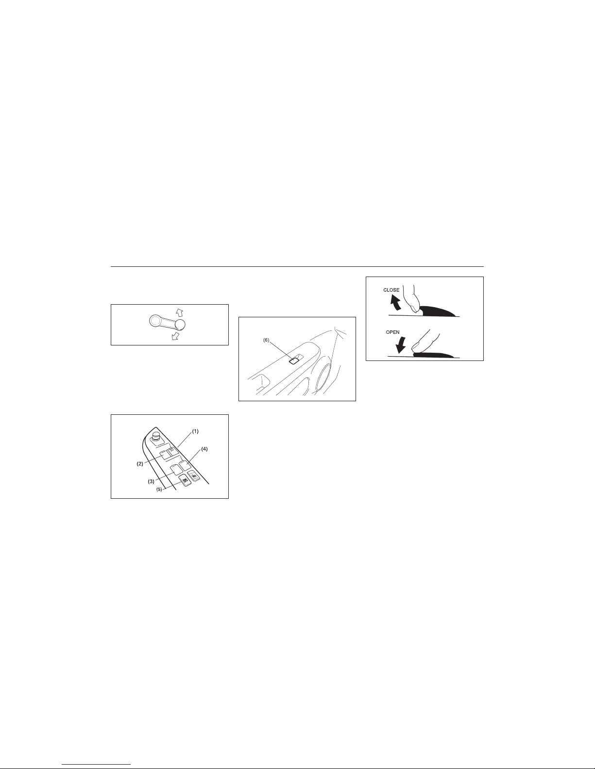
Electric Window Controls
(if equipped)
The electric windows can only be operated
when the ignition switch is in the “ON” position.
Driver’s door
83K-02-021
83K-02-022
The driver’s door has switches (1), (2), (3),
(4) to operate the driver’s window, the front
passenger’s window, the rear left window
and the rear right window, respectively.
Passenger’s door (if equipped)
The passenger’s door has a switch (6) to
operate that passenger’s window.
83K-02-023
EXAMPLE
EXAMPLE
EXAMPLE
83K-02-024
To open a window, push the top part of the
switch and to close the window, lift up the
top part of the switch.
The driver’s window has an “auto-down”
feature for added convenience (at toll
booths or drive-through restaurants, for
example). This means you can open the
window without holding the window switch
in the “Down” position. Press the driver’s
window switch completely down and release
it. To stop the window before it reaches the
bottom, pull the switch up briefly.
Lock switch (if equipped)
The driver’s door also has a lock switch (5)
for the passenger’s windows. When you
push in the lock switch, the passenger’s
windows can not be raised or lowered by
operating any of the switches (2), (3), (4)
Page 25
25
83K
BEFORE DRIVING
4-13
or (6). To restore normal operation, release
the lock switch by pushing again.
ww
ww
w WARNING
• You should always lock the passenger’s window operation when there
are children in the vehicle. Children
can be seriously injured if they get
part of their body caught by the
window during operation.
• To avoid injuring an occupant by
window entrapment, be sure no part
of the occupant’s body such as
hands or head is in the path of the
electric windows when closing them.
• Always remove the ignition key
when leaving the vehicle even if a
short time. Also do not leave children alone in a parked vehicle.
Unattended children could use the
electric window switches and get
trapped by the window.
Mirrors
Inside Rearview Mirror
83K-02-026
83K-02-026A
ww
ww
w WARNING
• Always adjust the mirror with the
selector set to the day position.
• Only use the night position if it is
necessary to reduce glare from the
headlights of vehicles behind you.
Be aware that in this position you
may not be able to see some
objects that could be seen in the
day position.
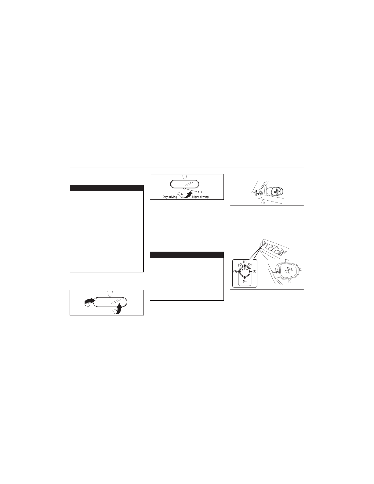
You can adjust the outside rearview mirrors
by hand with the knob (1) located on the
driver’s or front passenger’s door panel (If
equipped).
83K-02-027
Outside Rearview Mirrors
TYPE-1
83K-02-027A
TYPE-2
Electric Mirrors (if equipped)
The switch to control the electric mirrors is
located on the driver’s door panel. You can
adjust the mirrors when the ignition switch
is in the “ACC” or “ON” position. To adjust
the mirrors:
For Type 1 mirrors you can adjust the
inside rearview mirror by hand so as to
see the rear of your vehicle in the mirror.
For Type 2 mirrors adjust the mirror,set the
selector tab (1) to the day position,then
move the mirror up, down or sideways by
hand to obtain the best view. When driving
at night, you can move the selector tab to
the night position to reduce glare from the
headlights of vehicles behind you.
TYPE-1
TYPE-2
Page 26
26
83K
BEFORE DRIVING
4-14
NOTE:
• The defogger will work only when the
engine is running.
• The defogger will automatically turn off
after the defogger remains on for 15 minutes to prevent discharging of the battery.
Front Seats
Seat Adjustment
ww
ww
w WARNING
Never attempt to adjust the driver’s
seat or seatback while driving. The
seat or seatback could move unexpectedly, causing loss of control.
Make sure that the driver’s seat and
seatback are properly adjusted before
you start driving.
ww
ww
w WARNING
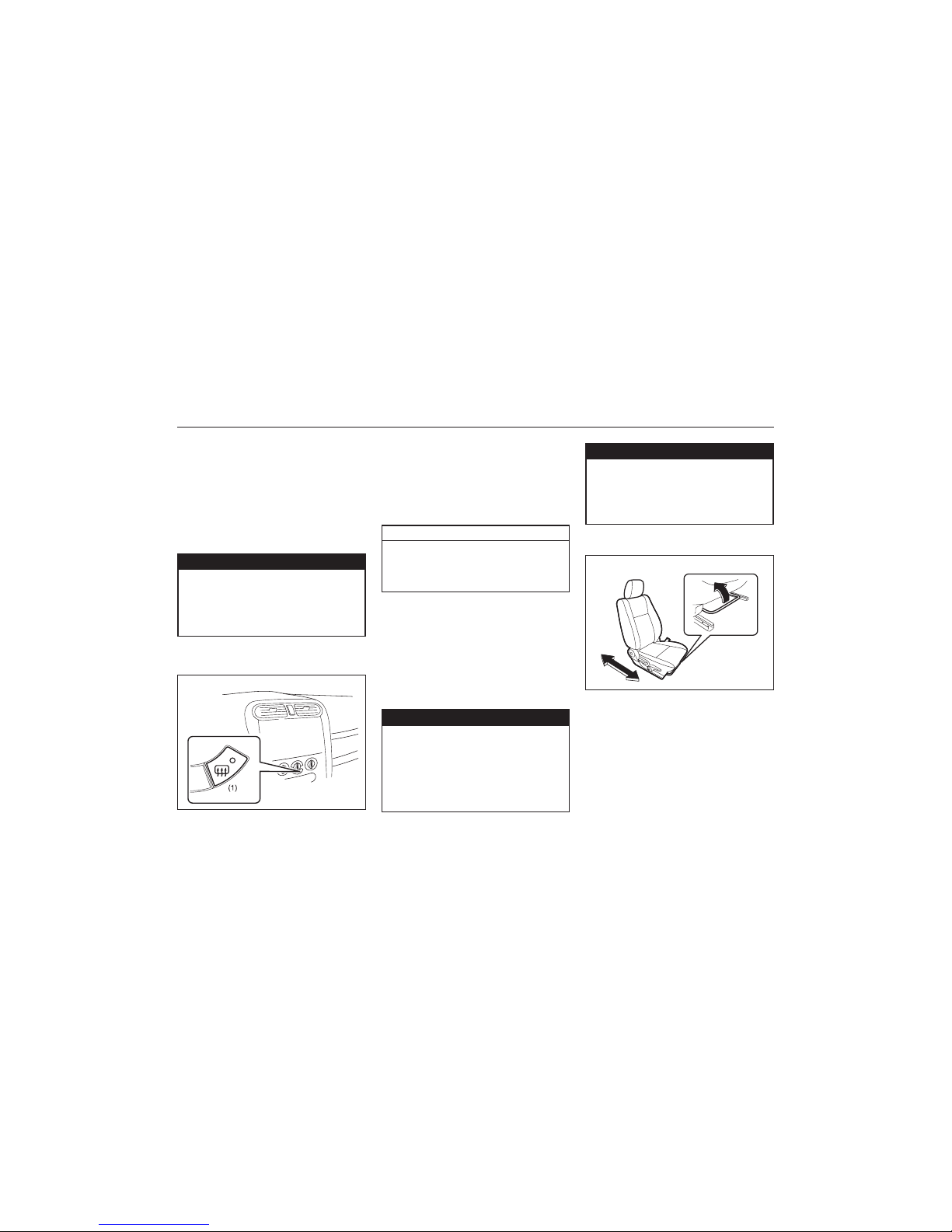
Heated Rear Window Switch (if
equipped)
83K-02-028
EXAMPLE
An indicator light will be lit when the defogger is on. The defogger will work only when
the engine is running. To turn off the
defogger, push the switch again.
CAUTION
The heated rear window (if equipped)
use a large amount of electricity. Be
sure to turn off after the window has
become clear.
When the rear window is misted, push this
switch (1) to clear the window.
Adjusting Seat Position
The adjustment lever for each front seat is
located under the front of the seat. To
adjust the seat position, pull up on the
adjustment lever and slide the seat forward
or rearward.
After adjustment, try to move the seat forward and rearward to ensure that it is
securely latched.
83K-02-029
EXAMPLE
1) Move the selector switch to the left or
right to select the mirror you wish to
adjust.
2) Press the outer part of the switch that
corresponds to the direction in which you
wish to move the mirror.
3) Return the selector switch to the center
position to help prevent unintended
adjustment.
ww
ww
w WARNING
Be careful when judging the size or
distance of a vehicle or other object
seen in the side convex mirror. Be
aware that objects look smaller and
appear farther away than when seen
in a flat mirror.
To avoid excessive seat belt slack,
which reduces the effectiveness of the
seat belts as a safety device, make
sure that the seats are adjusted before
the seat belts are fastened.
Page 27
27
83K
BEFORE DRIVING
4-15
ww
ww
w WARNING
• Never drive the vehicle with the
head restraints removed.
• Do not attempt to adjust the head
restraint while driving.
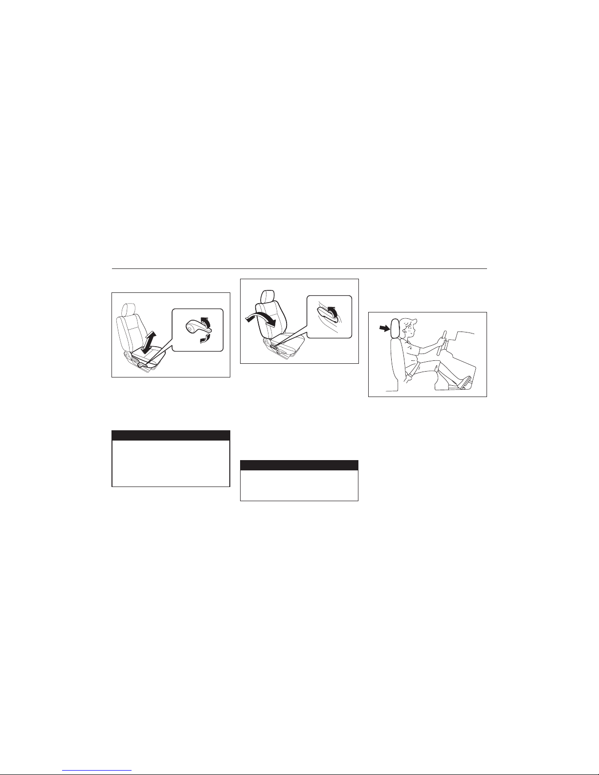
83K-02-031
To adjust the seatback angle of front seats,
pull up the lever on the outboard side of
the seat, move the seatback to the desired
position, and release the lever to lock the
seatback in place.
Adjustable Head Restraints
(if equipped)
Head restraints are designed to help reduce
the risk of neck injuries in the case of an
accident.
NOTE:
It may be necessary to recline the seatback
to provide enough overhead clearance to
remove the head restraint.
83K-02-032
Adjust the head restraint to the position
which places the center of the head restraint
closest to the top of your ears. If this is not
possible for very tall passengers, adjust the
head restraint as high as possible.
EXAMPLE
Seat Height Adjuster (if equipped)
If the driver’s seat is equipped with a seat
height adjuster lever on the outboard side
of the seat, raise or lower the seat by pulling up or down the adjuster lever.
Adjusting Seatbacks
83K-02-030
ww
ww
w WARNING
All seatbacks should always be in an
upright position when driving, or seat
belt effectiveness may be reduced.
Seat belts are designed to offer maximum protection when seatbacks are in
the upright position.
EXAMPLE
Page 28
28
83K
BEFORE DRIVING
4-16
Rear Seats
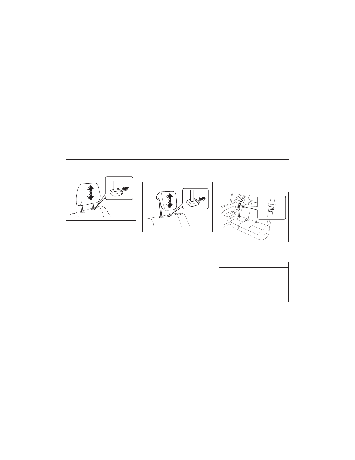
Adjustable Head Restraints
(if equipped)
83K-02-034
To raise the rear head restraint, pull upward
on the restraint until it clicks. To lower the
restraint, push down on the restraint while
holding in the lock lever. If a head restraint
is required to be removed (for cleaning,
replacement, etc.), push in the lock lever
and pull the head restraint all the way out.
When installing a child restraint system,
raise the head restraint to the most upper
position.
Folding Rear Seats (if equipped)
The rear seat(s) of your vehicle can be
folded forward to provide additional cargo
space.
To fold the rear seats forward:
1) Hook the webbing and the latch plate of
the outboard lap-shoulder belts in the
belt hangers.
83K-02-035
CAUTION
• When you move a seatback, make
sure both the latch plate and the
belt webbing are hooked in the seat
belt hangers so the seat belts are
not caught by the seatback, seat
hinge, or seat latch. This helps prevent damage to the belt system.
V
Front
To raise the front head restraint, pull
upward on the restraint until it clicks. To
lower the restraint, push down on the
restraint while holding in the lock lever. If
a head restraint must be removed (for
cleaning, replacement, etc.), push in the
lock lever and pull the head restraint all the
way out.
83K-02-033
EXAMPLE
Page 29
29
83K
BEFORE DRIVING
4-17
NOTICE
After folding the rear seatback forward, do not allow any foreign material to enter the lock opening. This
may cause damage to the inside of
the lock and prevent the seatback
from being locked securely.
ww
ww
w WARNING
If you need to carry cargo in the passenger compartment with the rear seat
back folded forward, be sure to secure
the cargo or it may be thrown about,
causing injury. Never pile cargo higher
than the seatbacks.
To return the seat to the normal position,
follow the procedure below.
When returning the rear seatback to
the normal position, be careful that
your finger is not caught between the
lock and the striker.
When returning the rear seatback to
the normal position, make sure that
there is nothing around the striker.
Any foreign materials prevent the
seatback from being locked securely.
83K-02-037
Raise the seatback until it locks into place.
After returning the seat, try moving the
seatback to make sure they are securely
latched.
Do not put your hand into the rear
seatback lock opening, or your finger
may get caught and be injured.
• When returning the rear seatback to
the normal position, do not allow
any foreign material to enter the
lock opening. This may prevent the
seatback from being locked
securely.
NOTICE
EXAMPLE
• When you hook the belt webbing
and latch plate into the seat belt
hanger, make sure the latch plate is
on the obverse side of the belt webbing as shown in the illustration.
• Make sure the belt webbing is not
twisted.
CAUTION
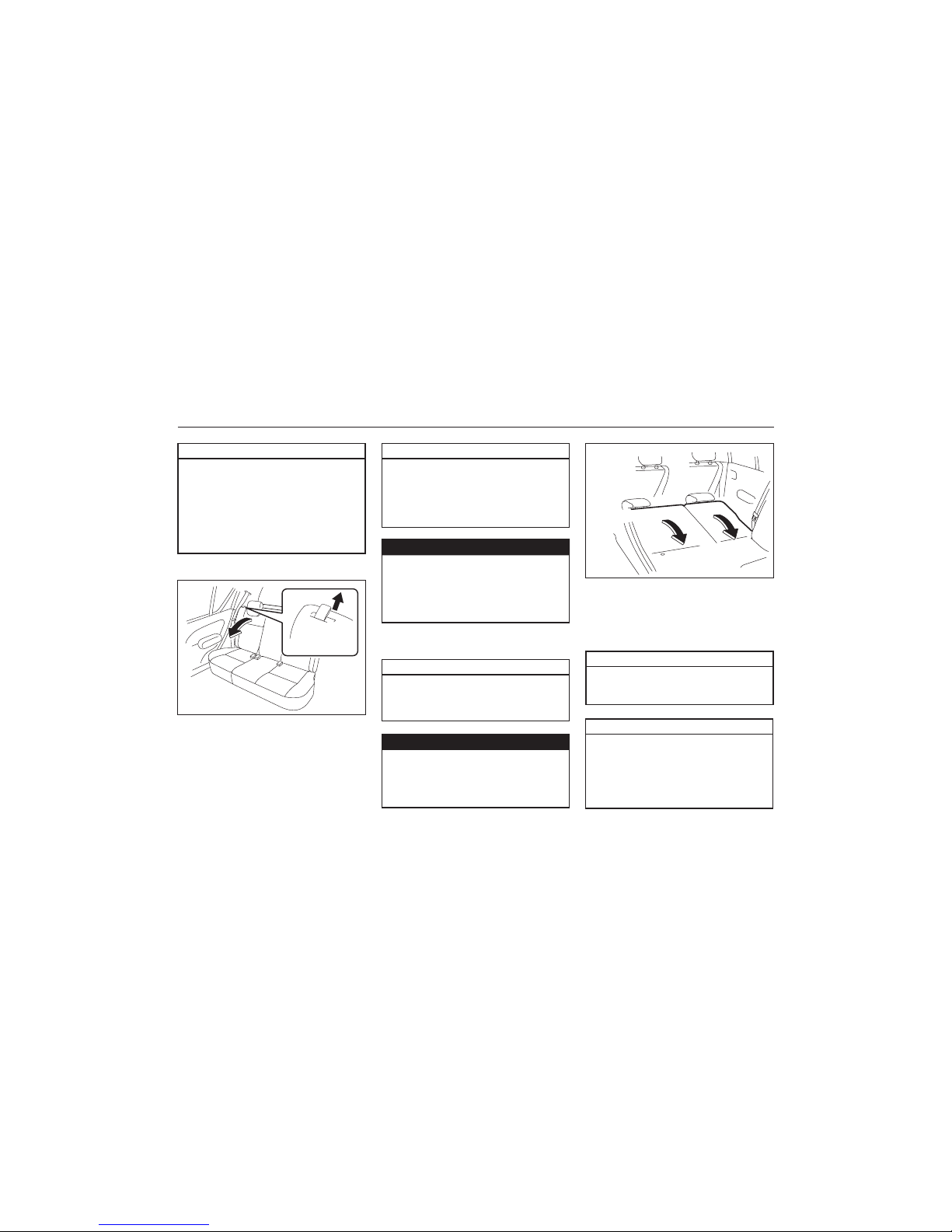
2) Lower the adjustable head restraint fully.
83K-02-036
3) For the split seat (if equipped), pull the
release lever on the top of each split
seat, and fold the seatbacks forward.
For the bench seat, pull the both release
levers on the top of the bench seat
together, and fold the seatback forward.
EXAMPLE
VV
VV
V
CAUTION
ww
ww
w WARNING
CAUTION
VV
VV
V
Page 30
30
83K
BEFORE DRIVING
4-18
ww
ww
w WARNING
An air bag supplements, or adds to,
the frontal crash protection offered by
seat belts. The driver and all passengers must be properly restrained
by wearing seat belts at all times,
whether or not an air bag is mounted
at their seating position, to minimize
the risk of severe injury or death in
the event of a crash.
83K-02-039
ww
ww
w WARNING
• Never allow persons to ride in the
cargo area of a vehicle. In the event
of an accident, there is a much
greater risk of injury for persons
who are not riding in a seat with
their seat belt securely fastened.
• Seat belts should always be
adjusted as follows:
– the lap portion of the belt should
be worn low across the pelvis, not
across the waist.
– the shoulder straps should be
worn on the outside shoulder
only, and never under the arm.
– the shoulder straps should be
away from your face and neck,
but not falling off your shoulder.
83K-02-040
NOTICE
• When returning the rear seatback to
the normal position, be sure to
handle it carefully by hand to avoid
any damage to the lock itself. Do
not push it by using some material
or by applying excessive force.
• As the lock is designed exclusively
for securing the rear seatback, do
not use it for any other purpose.
Incorrect use of it may cause
damage to the inside of the lock
and prevent the seatback from being
locked securely.
Seat Belts and Child Restraint
Systems
ww
ww
w WARNING
Wear Your Seat Belts at All Times.
83K-02-038
VV
VV
V
Page 31

31
83K
BEFORE DRIVING
4-19
ww
ww
w WARNING
ww
ww
w WARNING
VV
VV
V
VV
VV
V
VV
VV
V
ww
ww
w WARNING
• Seat belts should never be worn
with the straps twisted and should
be adjusted as tightly as is comfortable to provide the protection for
which they have been designed. A
slack belt will provide less protection than one which is snug.
• Make sure that each seat belt buckle
is inserted into the proper buckle
catch. It is possible to cross the
buckles in the rear seat.
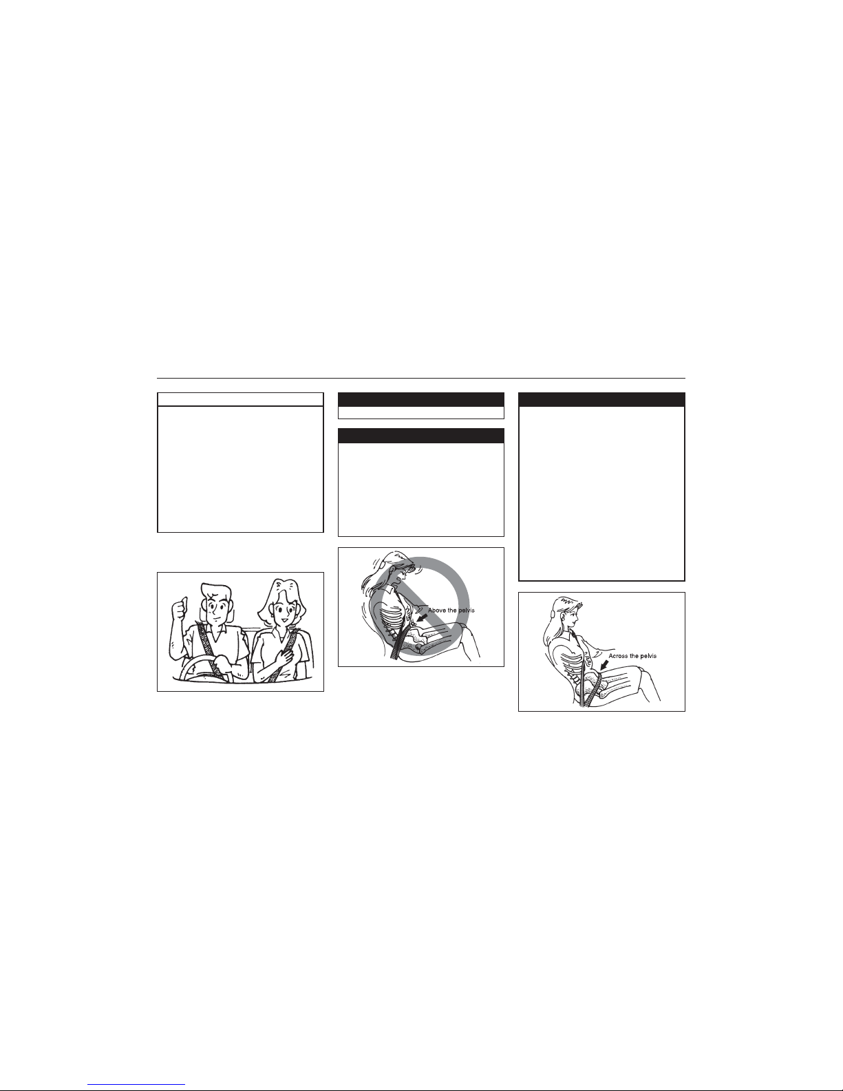
• Pregnant women should use seat
belts, although specific recommendations about driving should be
made by the woman’s medical advisor. Remember that the lap portion
83K-02-041
VV
VV
V
VV
VV
V
of the belt should be worn as low
as possible across the hips, as
shown in the diagram.
• Do not wear your seat belt over
hard or breakable objects in your
pockets or on your clothing. If an
accident occurs, objects such as
glasses, pens, etc. under the seat
belt can cause injury.
• Never use the same seat belt on
more than one occupant and never
attach a seat belt over an infant or
child being held on an occupant’s
lap. Such seat belt use could cause
serious injury in the event of an
accident.
• Periodically inspect seat belt
assemblies for excessive wear and
damage. Seat belts should be
replaced if webbing becomes frayed,
contaminated, or damaged in any
way. It is essential to replace the
entire seat belt assembly after it has
been worn in a severe impact, even
if damage to the assembly is not
obvious.
• Children age 12 and under should
ride properly restrained in the rear
seat.
• Infants and small children should
never be transported unless they are
properly restrained. Restraint
systems for infants and small children can be purchased locally and
should be used. Make sure that the
system you purchase meets applicable safety standards. Read and
follow all the directions provided by
the manufacturer.
• For children, if the shoulder belt
irritates the neck or face, move the
child closer to the center of the
vehicle.
• Avoid contamination of seat belt
webbing by polishes, oils,
chemicals, and particularly battery
acid. Cleaning may safely be carried
out using mild soap and water.
• Do not insert any items such as
coins, clips, etc. into the seat belt
buckles, and be careful not to spill
liquids into these parts. If foreign
materials get into a seat belt buckle,
the seat belt may not work properly.
• All seatbacks should always be in
an upright position when driving, or
seat belt effectiveness may be
reduced. Seat belts are designed to
offer maximum protection when
seatbacks are in the upright
position.
Page 32

32
83K
BEFORE DRIVING
4-20
83K-02-043
To reduce the risk of sliding under the belt
during a collision, position the lap portion
of the belt across your lap as low on your
hips as possible and adjust it to a snug fit
by pulling the shoulder portion of the belt
upward through the latch plate. The length
of the diagonal shoulder strap adjusts itself
to allow freedom of movement.
All Seat Belts Except Rear Centre
83K-02-044
To fasten the seat belt, sit up straight and
well back in the seat, pull the latch plate
attached to the seat belt across your body
and press it into the buckle until you hear
a “click”.
Lap-Shoulder Belt
Emergency Locking Retractor (ELR) (if
equipped)
The seat belt has an emergency locking
retractor (ELR), which is designed to lock
the seat belt only during a sudden stop or
impact. It also may lock if you pull the belt
across your body very quickly. If this happens, let the belt go back to unlock it, then
pull the belt across your body more slowly.
Safety reminder
83K-02-042
Page 33

33
83K
BEFORE DRIVING
4-21
NOTE:
The word “CENTER” is molded into the
buckle for the rear center belt. The buckles
are designed so a latch plate can not be
inserted into the wrong buckle.
Driver’s Seat Belt Reminder (if
equipped)
83K-02-047
When the driver doesn’t buckle his or her
seat belt, the driver’s seat belt reminder light
in the instrument cluster will come on or
blink, as a reminder to the driver to buckle
his or her seat belt.
The reminder will be automatically cancel
when the driver’s seat belt is buckled or the
ignition switch is turned off.
Shoulder Anchor Height Adjuster (if
equipped)
Adjust the shoulder anchor height so that
the shoulder belt rides on the center of the
outboard shoulder. To adjust the shoulder
anchor height, slide the anchor up or down
while pushing the lock button. After adjustment, make sure that the anchor is securely
locked.
83K-02-048
ww
ww
w WARNING
It is absolutely essential that the
driver and passengers wear their seat
belts at all times. Persons who are not
wearing seat belts have a much
greater risk of injury if an accident
occurs. Make a regular habit of buckling your seat belt before putting the
key in the ignition.
83K-02-045
To unfasten the belt, push the red “PRESS”
button on the buckle and allow the belt to
retract.
83K-02-046
EXAMPLE
Page 34

34
83K
BEFORE DRIVING
4-22
CAUTION
Seat Belt Inspection
Periodically inspect the seat belts to make
sure they work properly and are not damaged. Check the webbing, buckles, latch
plates, retractors, anchorages, and guide
loops. Replace any seat belts which do not
work properly or are damaged.
83K-04-050
ww
ww
w WARNING
Be sure to inspect all seat belt
assemblies after any collision. Any
seat belt assembly which was in use
during a collision (other than a very
minor one) should be replaced, even
if damage to the assembly is not
obvious. Any seat belt assembly
which was not in use during a collision should be replaced if it does not
function properly, it is damaged in any
way (that is, if the front air bags were
activated).
EXAMPLE
hinge, or seat latch. This helps prevent damage to the belt system.
• When you hook the belt webbing
and latch plate into the seat belt
hanger, make sure the latch plate is
on the obverse side of the belt webbing as shown in the illustration.
• Make sure the belt webbing is not
twisted.
83K-04-051
Child Restraint Systems
VV
VV
V
ww
ww
w WARNING
Be sure that the shoulder belt is positioned on the center of the outside
shoulder. The belt should be away
from your face and neck, but not falling off your shoulder. Misadjustment
of the belt could reduce the effectiveness of the safety belt in a crash.
Seat Belt Hanger (if equipped)
83K-04-049
EXAMPLE
• When you move a seatback, make
sure both the latch plate and the
belt webbing are hooked in the seat
belt hangers so the seat belts are
not caught by the seatback, seat
CAUTION
VV
VV
V
Page 35

35
83K
BEFORE DRIVING
4-23
Booster seat
83K-04-054
EXAMPLE
MARUTI SUZUKI highly recommends that
you use a child restraint system to restrain
infants and small children. Many different
types of child restraint systems are available;
make sure that the restraint system you
select meets applicable safety standards.
All child restraint systems are designed to
be secured on vehicle seats by either seat
belts (lap belts or the lap portion of lapshoulder belts) or by special rigid lower
anchor bars built into the seat. Whenever
possible, MARUTI SUZUKI recommends
that child restraint systems be installed on
the rear seat. According to accident statistics, children are safer when properly
restrained on rear seats than front passenger’s seat.
NOTE:
Observe any statutory regulation about child
restraints.
83K-04-055
ww
ww
w WARNING
If your vehicle is equipped with a front
passenger front air bag, do not install
a rear-facing child restraint in the
front passenger’s seat. If the passenger’s air bag inflates, a child in a
rear- facing child restraint could be
killed or seriously injured. The back of
a rear-facing child restraint would be
too close to the inflating air bag.
ww
ww
w WARNING
If you install a child restraint system
on the rear seat, slide the front seat
VV
VV
V
Infant restraint
Child restraint
83K-04-052
83K-04-053
EXAMPLE
EXAMPLE
Page 36
36
83K
BEFORE DRIVING
4-24
Children could be endangered in a
crash if their child restraints are not
properly secured in the vehicle. Be
sure to secure the child in the
restraint system according to the
manufacturer’s instructions.
ww
ww
w WARNING
ww
ww
w WARNING
far enough forward so that the child’s
feet do not contact the front seatback.
This will help avoid injury to the child
in the event of an accident.
83K-04-056
83K-04-057
VV
VV
V
Supplemental Restraint System (air bags)
(if equipped)
ww
ww
w WARNING
This section of the owner’s manual
describes the protection provided by
your MARUTI SUZUKI SUPPLEMENTAL RESTRAINT SYSTEM (air bags).
Please read and follow ALL these
instructions carefully to minimize your
risk of severe injury or death in the
event of a collision.
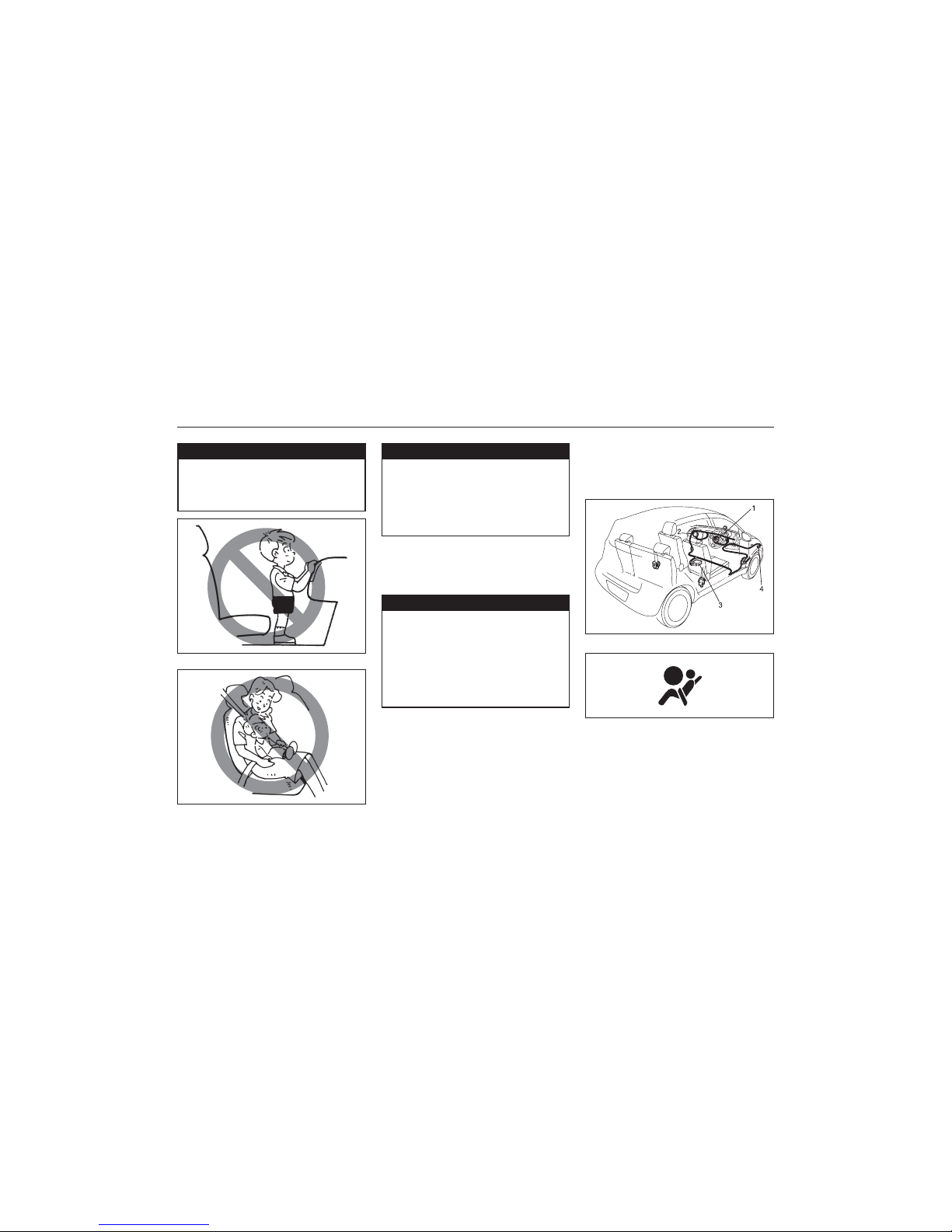
Your vehicle is equipped with a Supplemental Restraint System consisting of the
following components in addition to a lapshoulder belt at each front seating position.
1. Driver’s front air bag module
2. Front passenger’s front air bag module
3. Air bag controller
4. Forward crash sensor
83K-02-059
If the “AIR BAG” light on the instrument
cluster does not blink when the ignition
switch is first turned to the “ON” position,
or the “AIR BAG” light stays on, or comes
on while driving, the air bag system may
not work properly. Have the air bag system
83K-04-060
Page 37

37
83K
BEFORE DRIVING
4-25
behind the passenger’s side of the
dashboard. The words “SRS AIRBAG” are
molded into the air bag covers to identify
the location of the air bags.
Frontal collision range
83K-02-063
Front air bags will not inflate
83K-02-064
Front air bags will probably not inflate
83K-02-065
Front air bags are designed to inflate only
in severe frontal collisions. They are not
designed to inflate in rear impacts, side
impacts, rollovers or minor frontal collisions,
since they would offer no protection in those
types of accidents. Remember, since an air
bag deploys only one time during an
accident, seat belts are needed to restrain
occupants from further movements during
the accident.
Therefore, an air bag is NOT a substitute
for seat belts. To maximize your protection,
ALWAYS WEAR YOUR SEAT BELTS. Be
aware that no system can prevent all possible injuries that may occur in an accident.
inspected by a MARUTI SUZUKI authorized
dealer as soon as possible.
Front Air Bags
83K-02-061
EXAMPLE
83K-02-062
EXAMPLE
The driver’s front air bag is located behind
the center pad of the steering wheel and
the front passenger’s front air bag is located
Page 38

38
83K
BEFORE DRIVING
4-26
If you must use a front-facing child restraint
in the front passenger’s seat, be sure to
move the front passenger’s seat as far back
as possible. Please refer to the “Seat Belts
and Child Restraint Systems” section in the
“BEFORE DRIVING” section for details on
securing your child.
Air bag symbol (if equipped)
83K-04-067
EXAMPLE
You may find this label on the sun visor.
How the system works
In a frontal collision, the crash sensors will
detect rapid deceleration and send a signal
to the controller. if the controller judges that
the deceleration represents a severe frontal
crash, the controller will trigger the inflators.
The inflators inflate the appropriate air bags
with nitrogen or argon gas. The inflated air
bags provide a cushion for your head and
upper body. The air bag inflates and
deflates so quickly that you may not even
realize that it has activated. The air bag will
neither hinder your view nor make it harder
to exit the vehicle.
Air bags must inflate quickly and forcefully
in order to reduce the chance of serious or
fatal injuries. However, an unavoidable
consequence of the quick inflation is that
the air bag may irritate bare skin, such as
the facial area against a front air bag. Also,
upon inflation, a loud noise will occur and
some powder and smoke will be released.
These conditions are not harmful and do not
indicate a fire in the car. Be aware,
however, that some air bag components
may be hot for a while after inflation.
A seat belt helps keep you in the proper
position for maximum protection when an air
bag inflates. Adjust your seat as far back
as possible while still maintaining control of
ww
ww
w WARNING
An air bag supplements, or adds to, the
crash protection offered by seat belts.
The driver and all passengers must be
properly restrained by wearing seat
belts at all times, whether or not an air
bag is mounted at their seating
position, to minimize the risk of severe
injury or death in the event of a crash.
83K-04-066
ww
ww
w WARNING
Do not install a rear-facing chile
restraint in the front passenger’s seat.
if the passenger’s front air bag
inflates, a child in a rear-facing child
restraint could be killed or severely
injured. The back of a rear-facing chile
restraint would be too close to the
inflating air bag.
Page 39

39
83K
BEFORE DRIVING
4-27
ww
ww
w WARNING
• The driver should not lean over the
steering wheel. The front passenger
should not rest his or her body
against the dashboard, or otherwise
get too close to the dashboard. In
these situations, the out-of-position
occupant would be too close to an
inflating air bag, and may suffer
severe injury.
• Do not attach any objects to, or
place any objects over, the steering
wheel or dashboard. Do not place
any objects between the air bag and
the driver or front passenger. These
objects may interfere with air bag
operation or may be propelled by
the air bag in the event of a crash.
Either of these conditions may
cause severe injury.
83K-02-068
the vehicle. Sit fully back in your seat; sit
up straight; do not lean over the steering
wheel or dashboard. Front occupants should
not lean on or sleep against the door.
Please refer to the “Front Seat” section,
“Seat Belts and Child Restraint Systems”
section in this section for details on proper
seat and seat belt adjustments.
Note that even though your vehicle may be
moderately damaged in a collision, the collision may not have been severe enough to
trigger the front air bags to inflate. If your
car sustains ANY front-end or side damage,
have the air bag system inspected by an
authorized MARUTI SUZUKI dealer to
ensure it is in proper working order.
Your vehicle is equipped with a diagnostic
module which records information about the
air bag system. If the air bags deploy in a
crash, the module records information about
overall system status.
Servicing the air bag system
If the air bags inflate, have the air bags and
related components replaced by an authorized MARUTI SUZUKI dealer as soon as
possible.
If your vehicle ever gets in deep water and
the driver’s floor is submerged, the air bag
controller could be damaged. If it does, have
the air bag system inspected by the MARUTI
SUZUKI dealer as soon as possible.
Special procedures are required for servicing or replacing an air bag. For that reason,
only an authorized MARUTI SUZUKI dealer
should be allowed to service or replace your
air bags. Please remind anyone who
services your vehicle, that it has air bags.
83K-02-069
Page 40

40
83K
BEFORE DRIVING
4-28
1. Speedometer
2. Display
3. "MODE" knob
4. Tachometer (if equipped)
83K-02-071
83K-02-070
5. Fuel gauge
6. Warning and indicator lights
7. Clock knob
Instrument Cluster (For Petrol & Diesel)
Petrol
Diesel
Service on or around air bag components
or wiring must be performed only by an
authorized MARUTI SUZUKI dealer.
Improper service could result in unintended
air bag deployment or could render the air
bag inoperative. Either of these two
conditions may result in severe injury.
To prevent damage or unintended inflation
of the air bag system, be sure the battery
is disconnected and the ignition switch has
been in the “LOCK” position for at least 90
seconds before performing any electrical
service work on your MARUTI SUZUKI. Do
not touch air bag system components or
wires. The wires are wrapped with yellow
tape or yellow tubing, and the couplers are
yellow for easy identification.
Scrapping a car that has an uninflated air
bag can be hazardous. Contact your
MARUTI SUZUKI authorized dealer, body
repair shop or scrap yard for help with disposal.
According to accident statistics, children are
safer when properly restrained on rear seats
than front passenger’s seat. Whenever
possible, MARUTI SUZUKI recommends
that child restraint systems be installed on
the rear seat.
Page 41

41
83K
BEFORE DRIVING
4-29
The light also comes on together with the
ABS warning light when the rear brake force
control function (Proportioning valve
function) of the ABS system fails.
If the brake system warning light comes on
while you are driving the vehicle, it may
mean that there is something wrong with
the vehicle’s brake system. If this happens,
you should:
1) Pull off the road and stop carefully.
ww
ww
w WARNING
Remember that stopping distance may
be longer, you may have to push
harder on the pedal, and the pedal
may go down farther than normal.
ww
ww
w WARNING
• If the brake system warning light
does not go out after the engine
has been started and the parking
brake has been fully released.
• If the brake system warning light
does not come on when the ignition
switch is turned to the “ON” or
“START” position.
• If the brake system warning light
comes on at any time during vehicle operation.
2) Test the brakes by carefully starting and
stopping at the side of the road.
– If you determine that it is safe, drive
carefully at low speed to the nearest
MARUTI SUZUKI dealer for repairs, or
– Have the vehicle towed to the nearest
MARUTI SUZUKI dealer for repairs.
VV
VV
V
ww
ww
w WARNING
If any of the following conditions
occur, you should immediately ask
your MARUTI SUZUKI dealer to
inspect the brake system.
VV
VV
V
NOTE:
Because the disc brake system is selfadjusting, the fluid level will drop as the
brake pads become worn. Replenishing the
brake fluid reservoir is considered normal
periodic maintenance.
Seat Belt Warning Light (if
equipped)
This light blinks as a reminder until the
driver’s seat belt is buckled.
83K-02-073
Warning and Indicator Lights
Brake System Warning Light
For working check of this light, there are
following three different type operations
depending on the vehicle’s specification.
1) The light comes on briefly when the
ignition switch is turned to the “ON” and/
or “START” position.
2) The light comes on when the parking
brake is engaged with the ignition switch
in the “ON” position.
3) The light comes on when under either
or both of above two conditions.
The light also comes on when the fluid in
the brake fluid reservoir falls below the
specified level.
The light should go out after starting the
engine and fully releasing the parking brake,
if the fluid level in the brake fluid reservoir
is adequate.
83K-02-072
Page 42

42
83K
BEFORE DRIVING
4-30
“AIR BAG” Light (if equipped)
This light blinks or comes on for several
seconds when the ignition switch is turned
to the “ON” position so you can check if the
light is working.
The light will come on and stay on if there
is a problem in the air bag system.
83K-02-074
ww
ww
w WARNING
If the “AIR BAG” light does not blink
or come on briefly when the ignition
switch is turned to the “ON” position,
stays on for more than 10 seconds, or
comes on while driving, the air bag
system may not work properly. Have
both systems inspected by an authorized MARUTI SUZUKI dealer.
Anti-Lock Brake System (ABS)
Warning Light (if equipped)
83K-02-075
When the ignition switch is turned to the
“ON” position, the light comes on briefly so
you can check that the light is working.
If the light stays on, or comes on when
driving, there may be something wrong with
the ABS.
If this happens:
1) Pull off the road and stop carefully.
2) Turn the ignition switch to “LOCK” and
then start the engine again.
If the warning light comes on briefly then
turns off, the system is normal. If the warning light still stays on, there is something
wrong in the system.
If the light and the brake system warning
light stay on, or come on simultaneously
when driving, your ABS system is equipped
with the rear brake force control function
(Proportioning valve function) and there may
be something wrong with both the rear
brake force control function and anti-lock
function of the ABS system.
If one of these happens, have the system
inspected by your MARUTI SUZUKI dealer.
Malfunction Indicator Light
83K-02-076
If the ABS becomes inoperative, the brake
system will function as an ordinary brake
system that does not have this ABS system.
Your vehicle has a computer-controlled
emission control system. A malfunction
indicator light is provided on the instrument
panel to indicate when it is necessary to
have the emission control system serviced.
The malfunction indicator light comes on
when the ignition switch is turned to “ON”
position to let you know the light is working
and goes out when the engine is started.
If the malfunction indicator light comes on
or blinks when the engine is running, there
is a damage in the emission control system.
Bring the vehicle to your MARUTI SUZUKI
dealer to have the damage fixed.
Also, if the light comes on, there may be
something wrong with the transaxle system.
Page 43

43
83K
BEFORE DRIVING
4-31
Continuing to drive the vehicle when
the malfunction indicator light is on
can cause permanent damage to the
vehicle’s emission control system, and
can affect fuel economy and
driveability.
CAUTION
Have the system inspected by an authorized
MARUTI SUZUKI dealer.
This light comes on when the ignition switch
is turned to the “ON” position, and goes off
when the engine is started.
If this light comes on while driving, the
power steering system may not work properly. Have the system inspected by your
MARUTI SUZUKI dealer.
NOTE:
If the power steering system does not work
properly, you will feel heavier to steer but
you still will be able to steer.
83K-02-077
Electric Power Steering Light
This light comes on when the ignition switch
is turned to the “ON” position, and goes out
when the engine is started. The light will
come on and remain on if there is
insufficient oil pressure. If the light comes
on when driving, pull off the road as soon
as you can and stop the engine.
Check the oil level and add oil if necessary.
If there is enough oil, the lubrication system should be inspected by your MARUTI
SUZUKI dealer before you drive the vehicle again.
Oil Pressure Light
83K-02-078
CAUTION
• If you operate the engine with this
light on, severe engine damage can
result.
• Do not rely on the Oil Pressure
Light to indicate the need to add oil.
Be sure to periodically check the
engine oil level.
Charging Light
This light comes on when the ignition switch
is turned to the “ON” position, and goes off
when the engine is started. The light will
come on and remain on if there is
something wrong with the battery charging
system. If the light comes on when the
engine is running, the charging system
should be inspected immediately by your
MARUTI SUZUKI dealer.
High Engine Coolant Temperature
Warning Light (red color)
83K-02-079
83K-02-080
When the ignition switch is turned to the
“ON” position, this light comes on briefly so
you can check that the light is working. If
this light blinks while driving, it means the
engine is running hot. Avoid driving condi-
Page 44

44
83K
BEFORE DRIVING
4-32
CAUTION
Continuing to drive the vehicle when
engine overheating is indicated can
result in severe engine damage.
Immobilizer System Light (Petrol)
83K-02-081
tions that may lead to actual overheating.
If the light stays on without blinking, then
the engine is overheating. Follow the
instructions in the “If the Engine Overheats”
of “EMERGENCY SERVICE” section.
83K-02-082
This light comes on when the ignition switch
is turned to the “ON” position, and goes off
when the engine is started. If this light
blinks with the ignition switch turned to
“ON”, there may be something wrong with
the immobilizer system. Contact your
MARUTI SUZUKI dealer to have the system inspected.
Service Vehicle Soon (SVS) Light
(Diesel)
When the ignition switch is turned to the
“ON” position, this light comes on briefly.
If this light comes on when the engine is
running, there may be something wrong with
the engine electronics system. Ask your
MARUTI SUZUKI dealer to have the system
inspected.
If this light blinks with the ignition switch
turned "ON", there may be something wrong
with the immobilizer system. Ask your
MARUTI SUZUKI dealer to have the system
inspected.
Vehicle will not start in this condition.
Glow Plug Indicator Light
(Diesel)
83K-02-083
Open Door Warning Light
(if equipped)
83K-02-084
Turn Signal Indicators
83K-02-085
This light remains on until all doors (including or excluding the tailgate, depending on
specification of vehicle) are completely
closed.
When you turn on the left or right turn signals, the corresponding green arrow on the
instrument panel will flash along with the
respective turn signal lights. When you turn
on the hazard warning switch, both arrows
If the coolant temperature is cool enough,
this light comes on when the ignition switch
is turned on and goes out when the glow
plug is heated enough for engine starting.
Page 45

45
83K
BEFORE DRIVING
4-33
will flash along with all of the turn signal
lights.
Main Beam (high beam) Indicator
Light
83K-02-086
This indicator comes on when headlight
main beams (high beams) are turned on.
83K-02-087
Water in fuel filter warning light (if
equipped) (For diesel only)
If this light comes on, and keeps on glowing, get the water drained from the fuel filter.
83K-02-088
83K-02-088A
Automatic Transmission Warning
Light (if equipped)
This light comes on for several seconds
when the ignition switch is turned to the
“ON” position so you can check the light is
working. If this light comes on, there is the
problem with the automatic transmission
system. Ask your MARUTI SUZUKI dealer
to have the system inspected.
Transmission Selector Position
Indicator (if equipped)
83K-02-089
EXAMPLE
When the ignition switchs in the "ON"
position, the indicator shows the selector
position of automatice transmission.
Rear Fog Light Indicator Light (if
equipped)
The rear fog light indicator light comes on
when the rear fog light operates.
Page 46
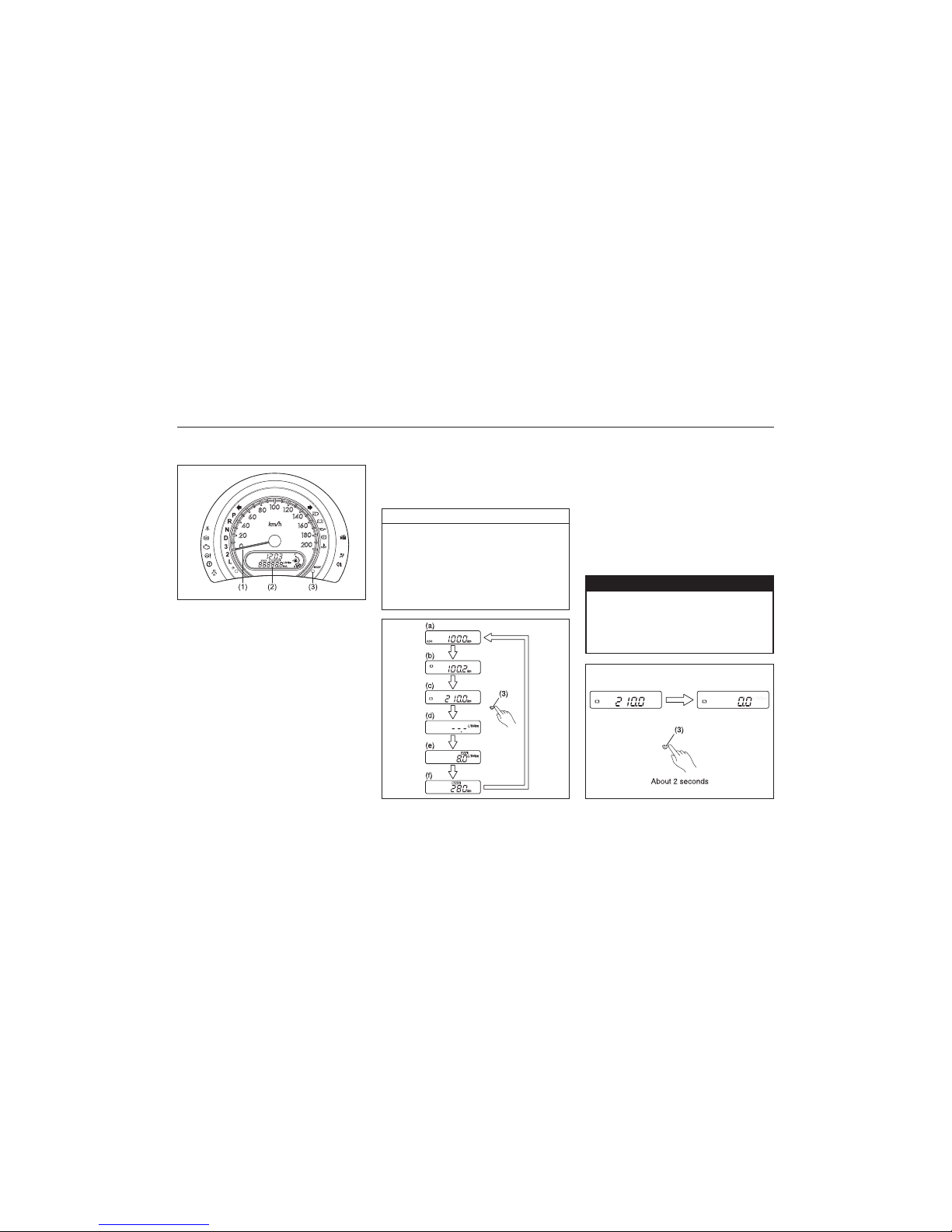
46
83K
BEFORE DRIVING
4-34
(1) Speedometer
(2) Display
(3) “MODE” knob
Speedometer
The speedometer indicates vehicle speed in
km/h.
Odometer/Trip meter
The odometer/trip meter is shown when the
ignition switch is in the “ON” position. The
odometer records the total distance the
vehicle has been driven. The trip meter can
be used to measure the distance traveled
on short trips or between fuel stops.
Speedometer/Odometer/Trip meter/
Meter Illumination Control
83K-02-090
EXAMPLE
NOTE:
When the ignition switch is turned to “ON”,
the display (2) shows the latest display that
the ignition switch was turned to “OFF” last
time.
Keep track of your odometer reading
and check the maintenance schedule
regularly for required services.
Increased wear or damage to certain
parts can result from failure to
perform required services at the
proper mileage intervals.
NOTICE
83K-02-091
When the ignition switch is turned to “ON”,
the display shows three or six types of
indication; odometer (a), trip meter A (b),
trip meter B (c), and if your vehicle is
equipped with the information display,
instantaneous fuel consumption (d), average
fuel consumption (e), and driving range (f).
Push the “MODE” knob (3) quickly to switch
the indication among three or six. For the
indication (d), (e), or (f), refer to “Information
Display” in this section for details.
If you attempt to adjust the display
while driving, you could lose control
of the vehicle.
Do not attempt to adjust the display
while driving.
ww
ww
w WARNING
83K-02-092
Page 47

47
83K
To reset the trip meter to zero, hold the
“MODE” knob (3) for more than 2 seconds
when the display (2) shows the indication
of trip meter (b) or (c).
Meter illumination control
83K-02-092A
When the display shows the indication of
trip meter B (c) or driving range (f) if your
vehicle is equipped with the information
display and the headlights are on, you can
change the indication to illumination intensity
by pushing the “MODE” knob (3).
To change the meter illumination brightness,
push and hold in the “MODE” knob (3). The
indication will change as shown in the
illustration. The illumination gets dimmer
then returns to the brightest condition after
it reaches the dimmest.
NOTE:
When you reconnect the negative (-)
terminal to the battery, the brightness of the
instrument panel lights will be reinitialized.
Readjust the brightness according to your
preference.
83K-02-093
83K-02-094
EXAMPLE
EXAMPLE
Never drive with the engine speed
indicator in the red zone or severe
engine damage can result.
When downshifting to a lower gear,
make sure not to operate with excessive revolution speeds of the engine.
Refer to “Downshifting maximum
allowable speeds” in the “OPERATING
YOUR VEHICLE” section.
CAUTION
Fuel Gauge
EXAMPLE
When the ignition switch is in the “ON”
position, this gauge gives an approximate
indication of the amount of fuel in the fuel
tank. “F” stands for full and “E” stands for
empty.
If the fuel meter indicator shows only one
segment to “E”, refill the tank as soon as
possible.
The mark (1) indicates that the fuel filler door
is located on the left side of the vehicle.
83K-02-095
Tachometer (if equipped)
(Petrol)
(Diesel)
The tachometer indicates engine speed in
revolutions per minute.
BEFORE DRIVING
4-35
Page 48

48
83K
Information Display
(1) Clock
(2) Instantaneous fuel consumption/Average
fuel consumption/ Driving range
(3) “MODE” knob
(4) Clock knob
83K-02-095A
NOTE:
• If the last segment blinks, it means that
the fuel tank is almost empty.
• The fuel meter indicator varies depend-
ing on road conditions (for example,
slope or curve) and driving conditions
because of fuel moving in the tank.
Clock (1)
The clock is shown when the ignition switch
is in the “ON” position.
To set the clock, follow the instructions
below.
• Hold in the clock knob (4) for more than
2 seconds. Push the clock knob (4) to
advance the minute display while the
minute display is flashing. Release the
clock knob (4) for 5 seconds to set the
minute display.
• The hour display flash after the minute
display is set. Push the clock knob (4)
to advance the hour display. Release the
clock knob (4) for 5 seconds to set the
hour display.
If you attempt to adjust the display
while driving, you could lose control
of the vehicle.
Do not attempt to adjust the display
while driving.
ww
ww
w WARNING
NOTE:
When you reconnect the negative (–)
terminal to the battery, the clock indication
will be reinitialized. Change the indication
again to your preference.
Fuel Consumption and Driving
Range (2)
This display can be changed to show
instantaneous fuel consumption, average
fuel consumption, or driving range. Also, the
display shows odometer and trip meter.
83K-02-091R
Every time you push the “MODE” knob (3),
the display will be changed among the
following six displays.
(a) Odometer
(b) Trip meter A
(c) Trip meter B
(d) Instantaneous fuel consumption
(if equipped)
(e) Average fuel consumption (if equipped)
(f) Driving range (if equipped)
BEFORE DRIVING
4-36
Page 49

49
83K
BEFORE DRIVING
4-37
ww
ww
w WARNING
If you attempt to adjust the display
while driving, you could lose control
of the vehicle.
Do not attempt to adjust the display
while driving.
NOTE:
Refer to “Speedometer/ Odometer/ Trip
meter” in this section for details of (a), (b),
and (c) indication.
Instantaneous fuel consumption (d) (if
equipped)
If you selected instantaneous fuel
consumption the last time you drove the
vehicle, the display indicates “—.-” when the
ignition switch is turned to the “ON” position.
Unless the vehicle is moving, the display will
indicate “—.-”.
NOTE:
• Depending on the vehicle’s specification,
the fuel consumption units of initial
setting are indicated as L/100km, km/L.
• For “L/100km” or “km/L” setting, the
indicated maximum value of
instantaneous fuel consumption is 30. No
more than 30 will be indicated on the
display even if the actual instantaneous
fuel consumption is higher.
Average fuel consumption (e) (if
equipped)
If you selected average fuel consumption
the last time you drove the vehicle, the
display shows the last value of average fuel
consumption when the ignition switch is
turned to the “ON” position. Unless you
reset the value of average fuel consumption,
the display indicates the value of average
fuel consumption which includes average
fuel consumption during previous driving.
To reset the value of average fuel
consumption, hold in the “MODE” knob (5)
for a while when the display shows the
average fuel consumption. The display will
indicate “—.-” and then will show a new
average fuel consumption value after driving
for a short time.
NOTE:
When you reset the indication or reconnect
the negative (–) terminal to the battery, the
value of average fuel consumption will be
shown after driving for a while.
Driving range (f) (if equipped)
If you selected driving range the last time
you drove the vehicle, the display shows “—
-” for a few seconds and then shows the
current driving range when the ignition
switch is turned to the “ON” position.
The driving range shown in the display is
NOTE:
• If you refuel when the ignition switch is
in the “ON” position, the driving range
may not indicate the correct value.
• When you reconnect the negative (–)
terminal to the battery, the value of
driving range will be shown after driving
for a while.
• For a new vehicle with low mileage, the
driving range may not be shown
promptly in the display when beginning
to drive. The driving range will be shown
after a while.
NOTE:
The values of fuel consumption and driving
range shown in the display are affected by
conditions such as the following;
the approximate distance you can drive until
the fuel gauge indicates “E” based current
driving conditions.
When the low fuel warning light comes on,
the display “—-” will appear.
If the low fuel warning light comes on, fill
the fuel tank immediately regardless of the
value of driving range shown in the display.
As the driving range after refueling is
calculated based on the last driving
condition,the value is different each time you
refuel.
Page 50

50
83K
• road condition
• surrounding traffic condition
• driving condition
• vehicle condition
• when the malfunction indicator light
comes on or blinks
Unit indication of fuel consumption
(For “L/100km” or “km/L” setting)
You can change the unit indication of fuel
consumption when selecting instantaneous
fuel consumption in the display.
You should operate the display before the
vehicle moves.
To change the unit indication in the display,
hold in the “MODE” knob (3) for more than
2 seconds.
Every time you hold in the “MODE” knob
(3) for more than 2 seconds, the unit
indication in the display will be changed
between the following two displays.
83K-04-095B
NOTE:
When you reconnect the negative (–)
terminal to the battery, the information
display will be reinitialized. Readjust the
display. If you select driving range, the
display will be shown after driving for a
while.
83K-02-096
ww
ww
w WARNING
To avoid possible injury, do not operate controls by reaching through the
steering wheel.
Lighting Control Lever
Lighting Operation
EXAMPLE
83K-02-097
To turn the lights on or off, twist the knob
on the end of the lever. There are three
positions:
BEFORE DRIVING
4-38
Page 51
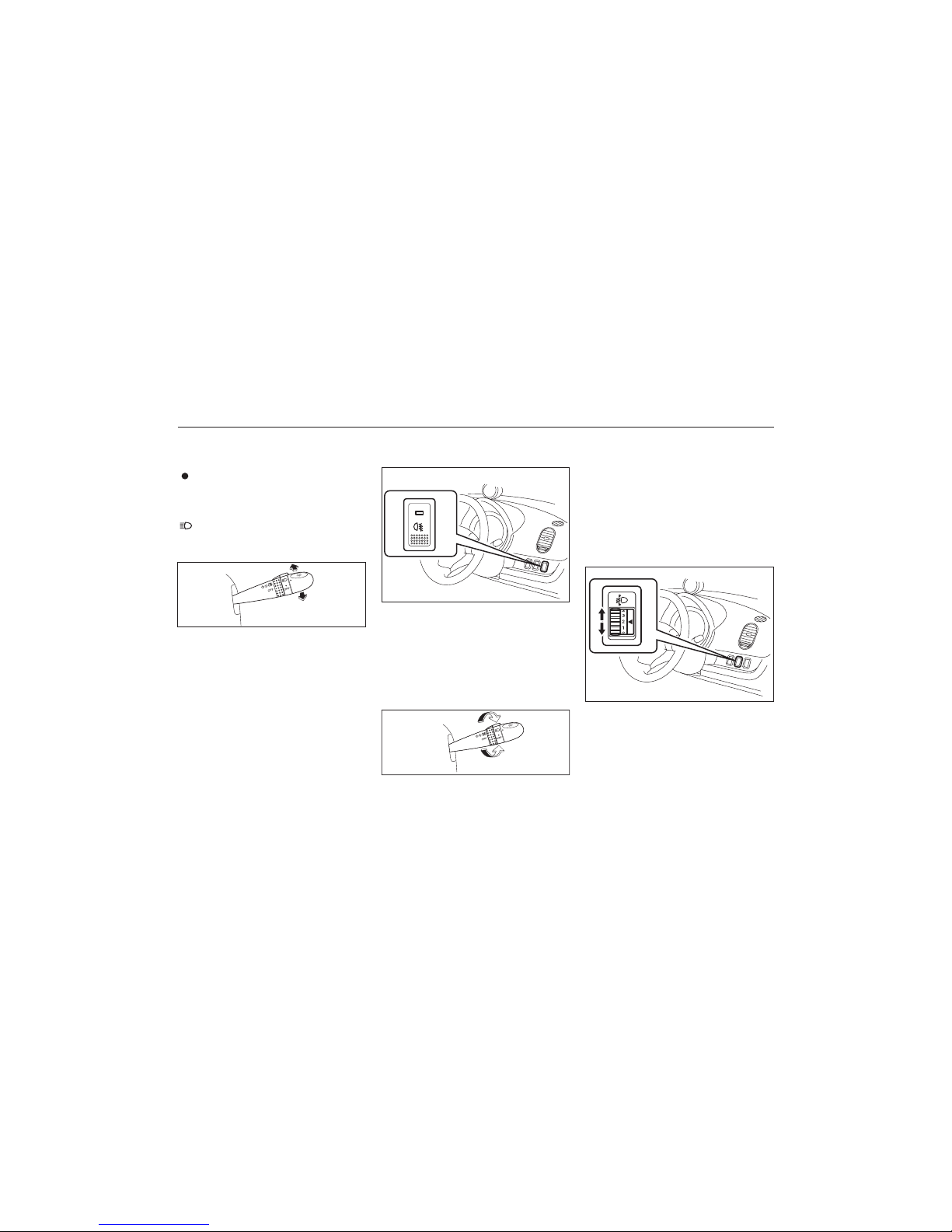
51
83K
EXAMPLE
83K-02-098
With the headlights on, push the lever forward to switch to the high beams (main
beams) or pull the lever toward you to
switch to the low beams. When the high
beams (main beams) are on, a light on the
instrument panel will come on. To momentarily activate the high beams (main beams)
as a passing signal, pull the lever slightly
toward you and release it when you have
completed the signal.
Lights “On” reminder (if equipped)
A buzzer/chime sounds to remind you to
turn off the lights if they are left on when
the ignition key is removed and the driver’s
door is opened.
OFF (1)
All lights are off.
(2)
Front parking lights, tail-lights, license plate
light and instrument lights are on, but
headlights are off.
(3)
Front parking lights, tail-lights, license plate
light, instrument lights and head lights are on.
Front Fog Light Switch
(if equipped)
83K-04-099
EXAMPLE
The front fog light comes on when the fog
light switch is pushed in with the head light
switch turned to the second and third position. An indicator light above the switch will
be lit when the front fog light is on.
Rear Fog Light Switch
(if equipped)
83K-02-100
To turn the rear fog light on, twist the knob
as shown in the illustration with the head-
light switch is in the third position. When the
rear fog light is on, an indicator light on the
instrument cluster will come on. Do not turn
the rear fog light switch unless the headlight
switch is in the third position.
NOTE:
When the head light switch is returned to
the “OFF” position, the rear fog light switch
will be cancelled automatically.
Headlight Leveling Switch
83K-02-101
EXAMPLE
Level the headlight beam according to the
load condition of your vehicle by turning this
switch. The chart below shows the
appropriate switch position for different
vehicle-load conditions.
BEFORE DRIVING
4-39
EXAMPLE
Page 52

52
83K
BEFORE DRIVING
4-40
Driver only 0 0
Driver + 1 passenger 0 0
(in front seat)
Driver + 4 passengers,
no cargo 2 2
Driver + 4 passengers,
cargo added 3 3
Driver + full cargo 4 4
Vehicle Load
Condition
Switch Position
Petrol Diesel
Turn Signal Control Lever
Turn Signal Operation
With the ignition switch in the “ON” position, move the lever up or down to activate
the right or left turn signals.
Normal turn signal
EXAMPLE
83K-02-102
Lane change signal
EXAMPLE
83K-02-103
Some times, such as when changing lanes,
the steering wheel is not turned far enough
to cancel the turn signal. For convenience,
you can flash the turn signal by moving the
lever part way and holding it there. The
lever will return to its normal position when
you release it.
Hazard Warning Switch
Move the lever all the way upward or
downward to signal. When the turn is completed, the signal will cancel and the lever
will return to its normal position.
83K-02-104
Windshield Wiper and Washer
Lever
Windshield Wipers
83K-02-105
EXAMPLE
Push in the hazard warning switch to activate the hazard warning lights. All turn sig-
nal lights and both turn signal indicators will
flash simultaneously. To turn off the lights,
push the switch again.
Use the hazard warning lights to warn other
traffic during emergency parking or when
your vehicle could otherwise become a
traffic hazard.
To turn the windshield wipers on, move the
lever down to one of the three operating
positions. In the “INT” position (if equipped),
the wipers operate intermittently. The “INT”
position is very convenient for driving in mist
or light rain. In the “LO” position, the wipers
operate at a steady low speed. In the “HI”
EXAMPLE
Page 53

53
83K
BEFORE DRIVING
4-41
position, the wipers operate at a steady high
speed. To turn off the wipers, move the
lever back to the “OFF” position.
Move the lever up and hold it to the “MIST”
position, the windshield wipers will turn on
continuously at low speed.
Windshield Washer
83K-02-106
ww
ww
w WARNING
• To prevent windshield icing in cold
weather, turn on the defroster to
heat the windshield before and during windshield washer use.
• Do not use radiator antifreeze in the
windshield washer reservoir. It can
severely impair visibility when
sprayed on the windshield, and can
also damage your vehicle’s paint.
EXAMPLE
CAUTION
To help prevent damage to the windshield wiper and washer system
components, you should take the following precautions:
• Do not continue to hold in the lever
when there is no windshield washer
fluid being sprayed or the washer
motor can be damaged.
• Do not attempt to remove dirt from
a dry windshield with the wipers or
you can damage the windshield and
the wiper blades. Always wet the
windshield with washer fluid before
operating the wipers.
• Clear ice or packed snow from the
wiper blades before using the wipers.
• Check the washer fluid level regularly. Check it often when the
weather is bad.
• Only fill the washer fluid reservoir 3/
4 full during cold weather to allow
room for expansion if the temperature
falls low enough to freeze the solution.
To spray windshield washer fluid, pull the
lever toward you. The windshield wipers will
automatically turn on at low speed.
EXAMPLE
83K-02-107
Rear Window Wiper/Washer
Switch (if equipped)
To turn the rear wiper on, twist the rear wiper
switch on the end of the lever forward to the
“ON” position. To turn the rear wiper off, twist
the switch rearward to the “OFF” position.
With the rear wiper in the “OFF” position,
twist the switch rearward and hold it there
to spray window washer fluid.
With the rear wiper in the “ON” position,
turn the switch forward and hold it there to
spray window washer fluid.
Clear ice or snow from the rear window and rear wiper blade before using
the rear wiper. Accumulated ice or
snow could prevent the wiper blade
from moving, causing damage to the
wiper motor.
CAUTION
Page 54
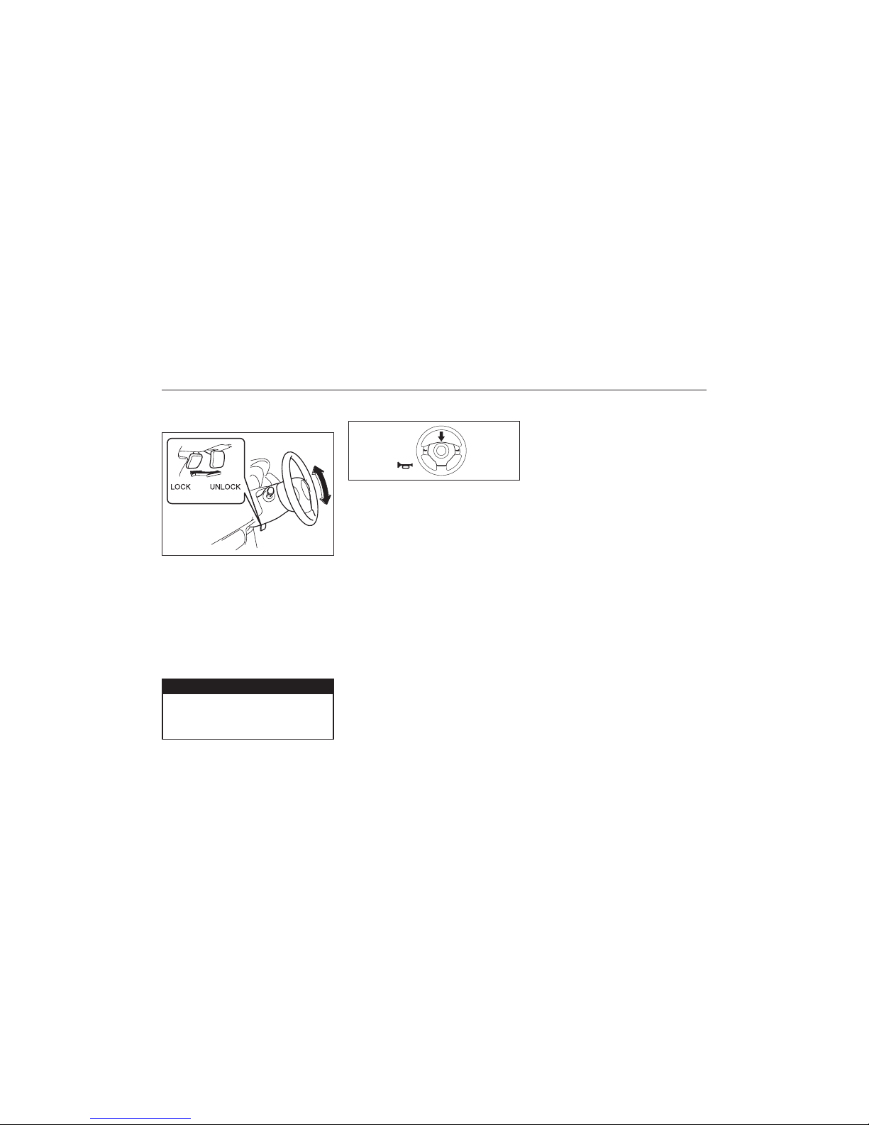
54
83K
BEFORE DRIVING
4-42
Tilt Steering Lock Lever
(if equipped)
83K-02-108
EXAMPLE
ww
ww
w WARNING
Never attempt to adjust the steering
wheel height while the vehicle is
moving or you could lose control of
the vehicle.
83K-02-109
Horn
Press the horn button of the steering wheel
to sound the horn. The horn will sound with
the ignition switch in any position.
EXAMPLE
The lock lever is located under the steering
column. To adjust the steering wheel height:
1) Pull up the lock lever to unlock the
steering column.
2) Adjust the steering wheel to the desired
height and lock the steering column by
push down the lock lever.
3) Try moving the steering wheel up and
down to make sure it is securely locked
in position.
Page 55

55
83K
OPERATING YOUR VEHICLE
Exhaust Gas Warning ........................................................................................................ 5-1
Daily Inspection Checklist ................................................................................................ 5-1
Engine Oil Consumption ................................................................................................... 5-2
Ignition Switch .................................................................................................................... 5-2
Parking Brake Lever .......................................................................................................... 5-4
Pedal ..................................................................................................................................... 5-4
Starting the Engine ............................................................................................................ 5-5
Using the Transmission .................................................................................................... 5-6
Braking.................................................................................................................................. 5-9
OPERATING YOUR VEHICLE
Page 56
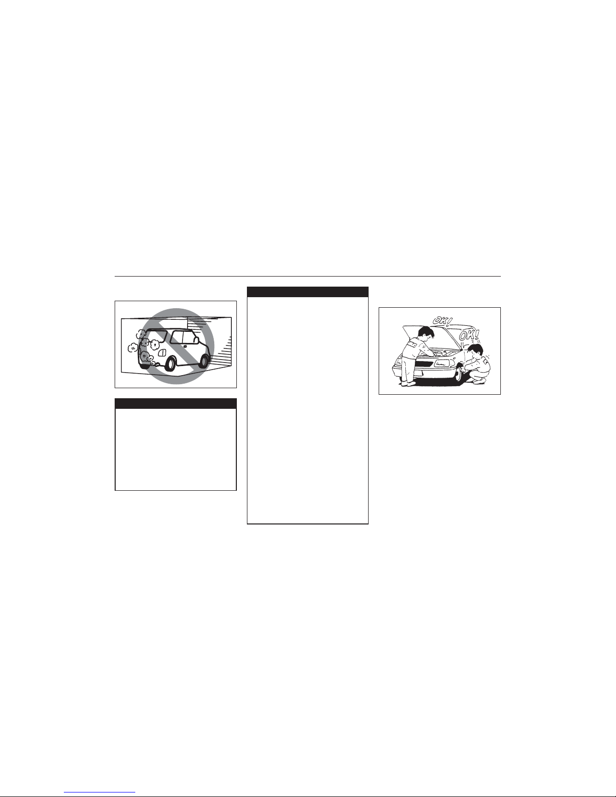
56
83K
Exhaust Gas Warning
83K-03-001
ww
ww
w WARNING
Avoid breathing exhaust gases.
Exhaust gases contain carbon monoxide, a potentially lethal gas that is
colorless and odorless. Since carbon
monoxide is difficult to detect by
itself, be sure to take the following
precautions to help prevent carbon
monoxide from entering your vehicle.
• Do not leave the engine running in
garages or other confined areas.
ww
ww
w WARNING
• Do not park with the engine running
for a long period of time, even in an
open area. If it is necessary to sit
for a short time in a parked vehicle
with the engine running, make sure
the air intake selector is set to
“FRESH AIR” and the fan is at high
speed.
• Avoid operating the vehicle with the
tailgate open. If it is necessary to
operate the vehicle with the tailgate
open, make sure all windows are
closed, and the blower is at high
speed with the air intake selector
set to “FRESH AIR”.
• To allow proper operation of your
vehicle’s ventilation system, keep
the air inlet grille in front of the
windshield clear of snow, leaves, or
other obstructions at all times.
• Keep the exhaust tailpipe area clear
of snow and other material to help
reduce the buildup of exhaust gases
under the vehicle. This is
particularly important when parked
in blizzard conditions.
• Have the exhaust system inspected
periodically for damage and leaks.
Any damage or leaks should be
repaired immediately.
Daily Inspection Checklist
Before Driving
1) Make sure that windows, mirrors, lights,
and reflectors are clean and unobstructed.
2) Visually check the tyres for the following
points:
– the depth of the tread groove
– abnormal wear, cracks and damage
– loose wheel bolts
– existence of foreign material such as
nails, stones, etc.
Refer to “Tyres” in “INSPECTION AND
MAINTENANCE” section for details.
3) Look for fluid and oil leaks.
NOTE:
It is normal for water to drip from the air
conditioning system after use.
83K-03-002
OPERATING YOUR VEHICLE
5-1
VV
VV
V
VV
VV
V
Page 57

57
83K
4) Make sure the bonnet is fully closed and
latched.
5) Check the headlights, turn signal lights,
brake lights and horn for proper operation.
6) Adjust the seat and adjustable head
restraint (if equipped).
7) Check the brake pedal and the parking
brake lever.
8) Adjust the mirrors.
9) Make sure that you and all passengers
have properly fastened your seat belts.
10)Make sure that all warning lights come
on as the key is turned to the “ON” or
“START” position.
11)Check all gauges.
12)Make sure that the BRAKE SYSTEM
WARNING light turns off when the
parking brake is released.
Once a week, or each time you fill your fuel
tank, perform the following under-hood
checks:
1) Engine oil level
2) Coolant level
3) Brake fluid level
4) Windshield washer fluid level
5) Battery solution level
6) Bonnet latch operation
Pull the Bonnet release handle inside the
vehicle. Make sure that you cannot open
the Bonnet all the way without releasing
the secondary latch. Be sure to close
the Bonnet securely after checking for
proper latch operation. See “All latches,
hinges & locks” of “CHASSIS AND
BODY” in the “Periodic Maintenance
Schedule” in the “INSPECTION AND
MAINTENANCE” section for lubrication
schedule.
ww
ww
w WARNING
Make sure the bonnet is fully closed
and latched before driving. If it is not,
it can fly up unexpectedly during
driving, obstructing your view and
resulting in an accident.
Once a month, or each time you fill your
fuel tank, check the tyre pressure using a
tyre pressure gauge. Also check the tyre
pressure of the spare tyre.
since its pistons, piston rings and cylinder
walls have not yet become conditioned. New
engines reach the normal level of oil
consumption only after approximately 5000
km (3000 miles) driving.
When judging the amount of oil consumption, note that the oil may become diluted
and make it difficult to accurately judge the
true oil level.
As an example, if a vehicle is used for
repeated short trips, and consumes a normal amount of oil, the dipstick may not
show any drop in the oil level at all, even
after 1000 km (600 miles) or more of driving. This is because the oil is gradually
becoming diluted with fuel or moisture,
making it appear that the oil level has not
changed.
You should also be aware that the diluting
ingredients evaporate out when the vehicle
is subsequently driven at high speeds, such
as on an expressway, making it appear that
oil is excessively consumed after high-speed
driving.
OPERATING YOUR VEHICLE
5-2
Engine Oil Consumption
It is normal for the engine to consume some
engine oil during normal vehicle operation.
The amount of engine oil consumed
depends on the viscosity of the oil, the
quality of the oil and the conditions the
vehicle is driven under.
More oil is consumed during high-speed
driving and when there is frequent acceleration and deceleration. Under high loads,
your engine also will consume more oil.
A new engine also consumes more oil,
83K-03-003
Ignition Switch
EXAMPLE
Page 58

58
83K
ww
ww
w WARNING
To avoid possible injury, do not operate controls by reaching through the
steering wheel.
83K-03-004
EXAMPLE
OPERATING YOUR VEHICLE
5-3
The ignition switch has the following four
positions:
LOCK
This is the normal parking position. It is the
only position in which the key can be
removed.
You must push in the key to turn it to the
“LOCK” position. It locks the ignition, and
prevents normal use of the steering wheel
after the key is removed.
To release the steering lock, insert the key
and turn it clockwise to one of the other
positions. If you have trouble turning the key
to unlock the steering, try turning the
steering wheel slightly to the right or left
while turning the key.
ACC
Accessories such as the radio can operate,
but the engine is off.
ON
This is the normal operating position. All
electrical systems are on.
START
This is the position for starting the engine
using the starter motor. The key should be
released from this position as soon as the
engine starts.
Ignition key reminder (if equipped)
A buzzer sounds intermittently to remind you
to remove the ignition key if it is in the ignition
switch when the driver’s door is opened.
ww
ww
w WARNING
• Never remove the ignition key while
the vehicle is moving. The steering
wheel will lock and you will not be
able to steer the vehicle.
• Always remove the ignition key
when leaving the vehicle even if a
short time. Also do not leave children alone in a parked vehicle.
Unattended children could cause
accidental movement of the vehicle
or could tamper with power windows. They also could suffer from
heat stroke in warm or hot weather.
These could result in severe injury
or even death.
NOTICE
• Do not use the starter motor for
more than 15 seconds at a time. If
the engine does not start, wait 15
seconds before trying again. If the
engine does not start after several
attempts, check the fuel and ignition
systems or consult your MARUTI
SUZUKI dealer.
• Do not leave the ignition switch in
the “ON” position if the engine is
not running as the battery will discharge.
83K-03-005
Page 59

59
83K
OPERATING YOUR VEHICLE
5-4
Parking Brake Lever
83K-03-006
ww
ww
w WARNING
• Never drive your vehicle with the
parking brake on: rear brake effectiveness can be reduced from overheating, brake life may be
shortened, or permanent brake
damage may result.
• If the parking brake does not hold
the vehicle securely or does not
(1) To apply
(2) To release
(3) To release
The parking brake lever is located between
the seats. To apply the parking brake, hold
the brake pedal down and pull the parking
brake lever all the way up. To release the
parking brake, hold the brake pedal down,
pull up slightly on the parking brake lever,
push the button on the end of the lever with
your thumb, and lower the lever to its original position.
VV
VV
V
ww
ww
w WARNING
VV
VV
V
ww
ww
w WARNING
Always apply the parking brake fully
before leaving your vehicle or it may
move, causing injury or damage.
When parking, make sure the gearshift
lever is in 1st gear or “R” (Reverse).
Remember, even though the
transmission is in gear, you must
apply the parking brake fully.
fully release, have your vehicle
inspected immediately by MARUTI
SUZUKI authorized dealer.
ww
ww
w WARNING
When parking the vehicle on a slope,
the following procedure should be
used:
1) Apply the parking brake.
2) Shift the transmission into reverse
or first gear.
3) With the engine off, get out of the
vehicle and put chocks under the
wheels.
4) Release the parking brake.
When you return to your vehicle,
you must remember to first apply
the parking brake, then remove the
wheel chocks.
EXAMPLE
Pedal
Manual transaxle
83K-03-007
EXAMPLE
Automatic transaxle
83K-03-008
EXAMPLE
Clutch Pedal (1)
(For manual transaxle)
The clutch pedal is used to disengage the
drive to the wheels when starting the
engine, stopping, or shifting the gearshift
lever. Depressing the pedal disengages the
clutch.
ww
ww
w WARNING
Do not drive with your foot resting on
the clutch pedal. It could result in
excessive clutch wear, clutch damage,
or unexpected loss of engine braking.
Page 60

60
83K
OPERATING YOUR VEHICLE
5-5
Brake Pedal (2)
Your SUZUKI vehicle is equipped with front
disc brakes and rear drum brakes.
Depressing the brake pedal applies both
sets of brakes.
You may hear occasional brake squeal
when you apply the brakes. This is a
normal condition caused by environmental
factors such as cold, wet, snow, etc.
ww
ww
w WARNING
If brake squeal is excessive and
occurs each time the brakes are
applied, you should have the brakes
checked by your SUZUKI dealer.
ww
ww
w WARNING
Do not “ride” the brakes by applying
them continuously or resting your foot
on the pedal. This will result in
overheating of the brakes which could
cause unpredictable braking action,
longer stopping distances, or
permanent brake damage.
Accelerator Pedal (3)
This pedal controls the speed of the engine.
Depressing the accelerator pedal increases
power output and speed.
Starting the Engine
Before Starting the Engine
83K-03-008A
1) Make sure the parking brake is set fully.
2) Manual transaxle – Shift into “N”
(Neutral) and depress the clutch pedal
all the way to the floor. Hold the clutch
pedal while starting the engine.
Automatic transaxle – If the gearshift
lever is not in “P” (Park) position, shift
into “P” (Park). (if you need to re-start
the engine while the vehicle is moving,
shift into “N”.)
NOTE:
Automatic transaxle vehicles have a starter
interlock device which is designed to keep
the starter from operating if the transaxle
is in any of the drive positions.
Make sure that the parking brake is set
fully and the transaxle is in Neutral
before attempting to start the engine.
ww
ww
w WARNING
Starting a Cold and Warm Engine
With your foot off the accelerator pedal,
crank the engine by turning the ignition key
to “START”. Release the key when the
engine starts.
NOTICE
• Stop turning the starter immediately
after the engine has started or the
starter system can be damaged.
• Do not crank the engine for more
than 15 seconds at a time. If the
engine doesn’t start on the first try,
wait about 15 seconds before trying
again.
If the engine does not start after 15
seconds of cranking, wait about 15 seconds,
then press down the accelerator pedal to
1/3 of its travel and try cranking the engine
again. Release the key and accelerator
pedal when the engine starts.
If the engine still does not start, try holding
the accelerator pedal all the way to the floor
while cranking. This should clear the engine
if it is flooded.
Page 61

61
83K
OPERATING YOUR VEHICLE
5-6
CAUTION
• Stop turning the starter immediately
after the engine has started or the
starter system can be damaged.
• Do not crank the engine for more
than 15 seconds at a time. If the
engine doesn’t start on the first try,
wait about 15 seconds before trying
again.
Warm engine
Crank the engine by turning the ignition key
to “START”. Release the key when the
engine starts.
CAUTION
When stopping the engine with turbocharger:
Downshifting Km/h
2nd to 1st 20
3rd to 2nd 54
4th to 3rd 80
5th to 4th 112
83K-03-009
Using the Transmission
Starting off
To start off, push in the clutch pedal and
change into 1st gear. After releasing the
parking brake, gradually release the clutch.
When you hear a change in the engine’s
sound, slowly press the accelerator while
continuing to gradually release the clutch.
Gear Changing
All forward gears are synchronized, which
provides for quiet, and easy changing.
Always push in the clutch pedal fully before
changing gears.
Downshifting maximum allowable
speeds
Petrol Engine
Downshifting Km/h
2nd to 1st 24
3rd to 2nd 60
4th to 3rd 92
5th to 4th 125
If the engine still does not start, try holding
the accelerator pedal all the way to the floor
while cranking. This should clear the engine
if it is flooded.
(For Diesel Engine Model)
Cold engine
Turn the ignition switch to the “ON” position
and wait until the glow plug indicator goes
out if it comes on. Crank the engine by
turning the ignition key to “START”. Release
the key when the engine starts.
• When stopping the engine after
climbing or high speed driving, let
the engine idle for about one minute
or more (if it is not prohibited) to
cool down the turbocharger and
engine oil. This is to prevent the
engine oil from over-deteriorating.
Deteriorated engine oil will damage
the bearings of the turbocharger.
Restarting diesel engine after fuelempty stop
The engine stops and the malfunction indicator light comes on if the engine feels fuel
emptiness. To restart the engine, stop the
vehicles, hold the ignition key in “ON” position for 5–10 seconds to feed fuel, then
perform above engine starting procedure.
Have the indicator light turned off by your
MARUTI SUZUKI dealer.
Diesel Engine
VV
VV
V
CAUTION
VV
VV
V
Page 62
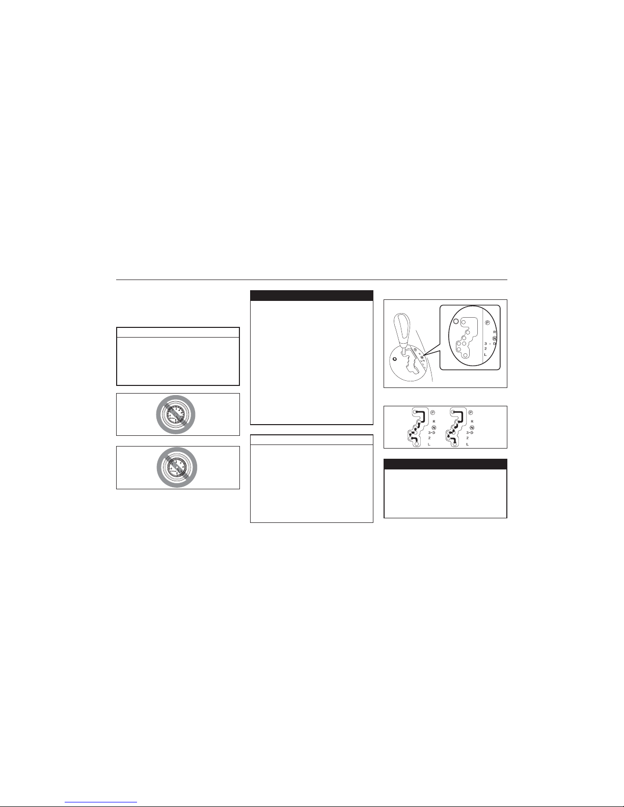
62
83K
OPERATING YOUR VEHICLE
5-7
Petrol
83K-03-010
Diesel
83K-03-011
CAUTION
When downshifting to a lower gear,
make sure not to operate with the
speed faster than the maximum
allowable speeds for the next lower
gear, or severe engine damage can
result.
Keep the engine speed so it does not get
into the red zone of tachometer.
ww
ww
w WARNING
CAUTION
• To help avoid clutch damage, do not
use the clutch pedal as a footrest
while driving or use the clutch to
keep the vehicle stationary on a
slope. Depress the clutch fully when
shifting.
• When shifting or starting off, do not
race the engine. Racing the engine
can shorten engine life and affect
smooth operation.
83K-03-011A
4-Speed Automatic Transaxle
Gearshift lever
83K-03-011B
ww
ww
w WARNING
Always depress the brake pedal before
shifting from “P” (Park) (or “N”
(Neutral) if the vehicle is stationary) to
a forward or reverse gear, to help
prevent the vehicle from moving
unexpectedly when you shift.
• Reduce your speed and downshift
to a lower gear before going down
a long or steep hill. A lower gear
will allow the engine to provide
braking. Avoid riding the brakes or
they may overheat, resulting in
brake failure.
• When driving on slippery roads, be
sure to slow down before changing
down. Excessive and or sudden
changes in engine speed may cause
loss of traction, which could cause
you to lose control.
• Make sure that the vehicle is completely stationary before you shift
into reverse.
NOTE:
You may not accelerate to the maximum
allowable speed because of the driving situation and/or the vehicle condition.
Page 63
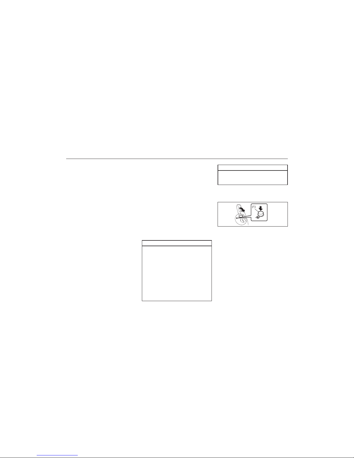
63
83K
OPERATING YOUR VEHICLE
5-8
Use the gearshift lever positions as
described below:
P (Park)
Use this position to lock the transaxle when
the vehicle is parked or when starting the
engine. Shift into Park only when the vehicle
is completely stationary.
R (Reverse)
Use this position to reverse the vehicle from
stop. Make sure that vehicle is completely
stationary before shifting into Reverse.
N (Neutral)
Use this position for starting the engine if the
engine stalls and you need to restart it while
the vehicle is moving. You may also shift into
Neutral and depress the brake pedal to hold
the vehicle stationary during idling.
D (Drive)
Use this position for all normal driving. With
the gearshift lever in “D” range you can get
an automatic downshift by pressing the
accelerator pedal. The higher the vehicle
speed is, the more you need to press the
accelerator pedal to get a downshift.
3 (Low 3)
Use this position for driving on moderate
uphill and downhill gradients. The engine
braking effect on moderate downhills can be
used in this position. The transaxle shifts up
only to 3rd gear.
2 (Low 2)
Use this position to provide extra power
when climbing hills, or to provide engine
braking when going down hills.
L (Low 1)
Use this position to provide maximum power
when climbing steep hills or driving through
deep snow or mud, or to provide maximum
engine braking when going down steep hills.
NOTE:
If you move the gearshift lever to a lower
gear while driving faster than the maximum
allowable speed for the lower gear, the
transaxle will not actually downshift until
your speed drops below the maximum
speed for the lower gear.
NOTICE
Be sure to take the following
precautions to help avoid damage to
the automatic transaxle:
• Make sure that the vehicle is
completely stationary before shifting
into “P” or “R”.
• Do not shift from “P” or “N” to “R”,
“D”, “3”, “2”, or “L” when the
engine is running above idle speed.
• Do not rev the engine with the
transaxle in a drive position (“R”,
“D”, “3”, “2”, or “L”) and the front
wheels not moving.
If You Cannot Shift Automatic Transaxle Gearshift Lever Out of “P”
(PARK)
83K-03-011C
Vehicles with an automatic transaxle have
an electrically operated park-lock feature. If
the vehicle’s battery is discharged, or there
is some other electrical failure, the
automatic transaxle cannot be shifted out of
Park in the normal way. Jump starting may
correct the condition. If not, follow the
procedure described below. This procedure
will permit shifting the transaxle out of Park.
NOTICE
• Do not use the accelerator to hold
the vehicle on a hill. Use the
vehicle’s brakes.
1) Be sure the parking brake is firmly
applied.
2) If the engine is running, stop the engine.
3) Make sure the key is in the “ON” or
“ACC” position.
Page 64

64
83K
ww
ww
w WARNING
If water gets into the brake drums,
brake performance may become poor
and unpredictable.
After driving through water or washing the underside of the vehicle, test
the brakes while driving at a slow
speed to see if they have maintained
their normal effectiveness. If the
brakes are less effective than normal,
dry them by repeatedly applying the
brakes while driving slowly until the
brakes have regained their normal
effectiveness.
ww
ww
w WARNING
Even without reserve power in the
brake system, you can still stop the
vehicle by pressing the brake pedal
harder than normally required. However, the stopping distance may be
longer.
OPERATING YOUR VEHICLE
5-9
Braking
83K-03-012
EXAMPLE
4) With pushing the release button (1), shift
the gearshift lever to the desired
position.
This procedure is for emergency use only.
If repeated use of this procedure is
necessary, or the procedure does not work
as described, take the vehicle to your dealer
for repair.
The distance needed to bring any vehicle
to a halt increases with the speed of the
vehicle. The braking distance needed, for
example, at 60 km/h (37 mph) will be
approximately 4 times greater than the
braking distance needed at 30 km/h (19
mph). Start to brake the vehicle when there
is plenty of distance between your vehicle
and the stopping point, and slow down
gradually.
Power Assisted Brakes (if
equipped)
Your vehicle has power assisted brakes. If
power assistance is lost due to a stalled
engine or other failures, the system is still
fully operational on reserve power and you
can bring the vehicle to a complete stop by
pressing the brake pedal once and holding
it down. The reserve power is partly used
up when you depress the brake pedal and
reduces each time the pedal is pressed.
Apply smooth and even pressure to the
pedal. Do not pump the pedal.
Anti-Lock Brake System (ABS)
(if equipped)
ABS will help you avoid skidding by electronically controlling braking pressure. It will
also help you maintain steering control when
braking on slippery surfaces or when
braking hard.
The ABS works automatically, so you do not
need any special braking technique. Just
push the brake pedal down without
pumping. The ABS will operate whenever it
senses that the wheels are locking up. You
may feel the brake pedal moves a little
while the ABS is operating.
NOTE:
The ABS will not work if vehicle speed is
under about 10 km/h (6 mph).
Page 65

65
83K
OPERATING YOUR VEHICLE
5-10
(1) ABS warning light
(2) Brake system warning light
ww
ww
w WARNING
• If the ABS warning light (1) on the
instrument panel comes on and
stays on while driving, there may be
a problem with the ABS system.
Ask your MARUTI SUZUKI dealer to
inspect the ABS system immediately. If the ABS system becomes
inoperative, the brake system will
function as an ordinary brake system that has no ABS.
• If the ABS warning light (1) and the
Brake system warning light (2) on
the instrument panel simultaneously
stays on or comes on when driving,
both anti-lock function and rear
brake force control function
(Proportioning valve function) of the
ABS system may have failed. If so,
the rear wheels may easily skid or
the vehicle can even spin in the
83K-03-013
VV
VV
V
ww
ww
w WARNING
VV
VV
V
ww
ww
w WARNING
The ABS may not work properly if
tyres or wheels other than those
specified in the owner’s manual are
used. This is because the ABS works
by comparing changes in wheel
speed. When replacing tyres or
wheels, use only the size and type
specified in this owner’s manual.
worst case when braking on a
slippery road or when hard braking
even on a dry paved road. Contact
your MARUTI SUZUKI dealer to
inspect the ABS system immediately.
Drive carefully, avoiding hard braking
as much as possible.
How the ABS Works
A computer continuously monitors wheel
speed. The computer compares the
changes in wheel speed when braking. If
the wheels slow suddenly, indicating a
skidding situation, the computer will change
braking pressure several times each second
to prevent the wheels from locking. When
you start your vehicle after a stop you may
hear a momentary motor noise as the
system checks itself.
ww
ww
w WARNING
• On some types of loose surfaces
(such as gravel, snow-covered
roads, etc.) the stopping distance
required for an ABS-equipped vehicle may be slightly greater than for
a comparable vehicle with a conventional brake system. With a
conventional brake system, skidding
tyres are able to “plow” the gravel
or snow layer, shortening the
stopping distance, ABS minimizes
this resistance effect. Allow for extra
stopping distance when driving on
loose surfaces.
• On regular paved roads, some drivers may be able to obtain slightly
shorter stopping distances with
conventional brake systems than
with ABS.
• In both of the above conditions,
ABS will still offer the advantage of
helping you maintain directional
control. However, remember that
ABS will not compensate for bad
road or weather conditions or poor
driver judgment. Use good judgment
and do not drive faster than
conditions will safely allow.
Page 66

66
83K
DRIVING TIPS
Running-in ............................................................................................................................ 6-1
Catalytic Converter............................................................................................................. 6-1
Improving Fuel Economy .................................................................................................. 6-2
Highway Driving .................................................................................................................. 6-3
Driving on Hills ................................................................................................................... 6-3
Driving on Slippery Roads ............................................................................................... 6-3
Do's and Don'ts for Safe Driving ................................................................................... 6 -5
DRIVING TIPS
Page 67

67
83K
• Wear Your Seat Belts at All Times,
even if air bags are equipped at the
front seating positions. The driver
and all passengers should be properly restrained at all times, using
the seat belts provided. Refer to the
“Seat Belts and Child Restraint
Systems” section for instructions on
proper use of the seat belts.
• Never drive while under the influence of alcohol or other drugs.
Alcohol and drugs can seriously
impair your ability to drive safely,
greatly increasing the risk of injury
to yourself and others. You should
also avoid driving when you are
tired, sick, irritated, or under stress.
The future performance and reliability
of the engine depends on the care
and restraint exercised during its early
life. It is especially important to
observe the following precautions
during the initial 960 km (600 miles)
of vehicle operation.
• After starting, do not race the
engine. Warm it up gradually.
• Avoid prolonged vehicle operation at
a constant speed. Moving parts will
break in better if you vary your
speed.
• Start off from a stop slowly. Avoid
full throttle starts.
• Avoid hard braking, especially during the first 320 km (200 miles) of
driving.
• Do not drive slowly with the transmission in a high gear.
• Drive the vehicle at moderate engine
speeds.
83K-04-001
ww
ww
w WARNING
Running-in
CAUTION
Catalytic Converter
The purpose of the catalytic converter is to
minimize the amount of harmful pollutants
in your vehicle’s exhaust. Use of leaded fuel
in vehicles equipped with catalytic
converters is prohibited, because lead
deactivates the pollutant-reducing components of the catalyst system.
The converter is designed to last the life of
the vehicle under normal usage and when
unleaded fuel is used. No special maintenance is required on the converter. However, it is very important to keep the engine
properly tuned. Engine misfiring, which can
result from an improperly tuned engine
loose writing etc., may cause overheating
of the catalyst. This may result in permanent heat damage to the catalyst and other
vehicle components.
83K-04-002
DRIVING TIPS
6-1
Page 68

68
83K
To minimize the possibility of catalyst
or other vehicle damage:
• Maintain the engine in the proper
operating condition.
• In the event of an engine malfunction, particularly one involving
engine misfire or other apparent
loss of performance, have the vehicle serviced promptly.
• Do not turn off the engine or interrupt the ignition when the transmission is in gear and the vehicle is in
motion.
• Do not try to start the engine by
pushing or towing the vehicle, or
coasting down a hill.
• Do not idle the engine with any
spark plug wires disconnected or
removed, such as during diagnostic
testing.
• Do not idle the vehicle for prolonged periods if idling seems rough
or there are other malfunctions.
• Do not allow the fuel tank to get
near the empty level.
Be careful where you park and drive;
the catalytic converter and other
exhaust components can get very hot.
As with any vehicle, do not park or
operate this vehicle in areas where
combustible materials such as dry
grass or leaves can come in contact
with a hot exhaust system.
ww
ww
w WARNING
83K-04-003
engine, do not allow the engine to idle or
apply full throttle until the engine has
reached operating temperature. Allow the
engine to warm up by driving.
Avoid “fast” starts
Fast starts away from lights or stop signs
will consume fuel unnecessarily and shorten
engine life. Start off slowly.
Avoid unnecessary stops
Avoid unnecessary deceleration and stopping. Try to maintain a slow, steady speed
whenever possible. Slowing down and then
accelerating again uses more fuel.
Keep a steady cruising speed
Keep as constant a speed as road and traffic conditions will permit.
DRIVING TIPS
6-2
CAUTION
Improving Fuel Economy
The following instructions will help you
improve fuel economy.
Avoid excessive idling
If you are to wait for more than a minute
while you are parked, stop the engine and
start it again later. When warming up a cold
Keep the air cleaner clean
(Petrol engine)
EXAMPLE
83K-04-004
A dirty air cleaner will cause the fuel system to supply too much fuel to the engine
for the amount of air being supplied. The
result is waste of fuel due to incomplete
combustion.
Page 69

69
83K
DRIVING TIPS
6-3
(Diesel engine)
No cleaning is required. Replace as per
periodic maintenance schedule.
Keep weight to a minimum
The heavier the load, the more fuel the
vehicle consumes. Take out any luggage or
cargo when it is not necessary.
Keep tyre pressures correct
Underinflation of the tyres can waste fuel
due to increased running resistance of the
tyres. Keep your tyres inflated to the correct pressure shown on the label on the
driver’s side door pillar.
Highway Driving
When driving at high speeds, pay attention
to the following:
• Stopping distance progressively increases with vehicle speed. Apply the brakes
far enough ahead of the stopping point
to allow for the extra stopping distance.
• On rainy days, “Aquaplaning” can occur.
“Aquaplaning” is the loss of direct contact between the road surface and the
vehicle’s tyres due to a water film forming between them. Steering or braking
the vehicle while “Aquaplaning” can be
very difficult, and loss of control can
occur. Keep speed down when the road
surface is wet.
• At high speeds, the vehicle may be
affected by side winds. Therefore, reduce
speed and be prepared for unexpected
buffeting, which can occur at the exits
of tunnels, when passing by a cut of a
hill, or when being overtaken by large
vehicles, etc.
Driving on Hills
ww
ww
w WARNING
Try not to hold the brake pedal down
too long or too often while going
down a steep or long hill. This could
cause the brakes to overheat, resulting in reduced braking efficiency.
Failure to take this precaution could
result in loss of vehicle control.
CAUTION
When descending a down hill, NEVER
turn the ignition key to the “OFF”
position. Emission control system
damage may result.
Driving on Slippery Roads
83K-04-006
83K-04-005
• When climbing steep hills, the car may
begin to slow down and show a lack of
power. If this happens, you should shift
to a lower gear so that the engine will
again be operating in its normal power
range. Change rapidly to prevent the car
from losing momentum.
• When driving down a hill, the engine
should be used for braking by moving
to next lower gear.
Page 70

70
83K
DRIVING TIPS
6-4
ww
ww
w WARNING
Do not allow anyone to stand near the
vehicle when you are rocking it, and
do not spin the wheels faster than an
indicated 40 km/h (25 mph) on the
speedometer. Personal injury and/ or
vehicle damage may result from spinning the wheels too fast.
CAUTION
83K-04-007
Do not continue rocking the vehicle
for more than a few minutes. Prolonged rocking can cause engine
overheating or transmission damage.
Under wet road conditions you should drive
at a lower speed than on dry roads due to
possible slippage of tyres during braking.
When driving on icy, snow-covered, or
muddy roads, reduce your speed and avoid
sudden acceleration, abrupt braking, or
sharp steering movements.
If Your Vehicle Gets Stuck
If your vehicle gets stuck in snow, mud, or
sand, follow the directions below:
1) Change back and forth between first
gear and reverse. This will create a
rocking motion which may give you
enough momentum to free the vehicle.
Press gently on the accelerator to keep
wheel spinning to a minimum wheel rpm.
Remove your foot from the accelerator
while changing gear.
Do not race the engine. Excessive wheel
spin will cause the tyres to dig deeper,
making it more difficult to free the
vehicle.
2) If your vehicle remains stuck after a few
minutes of rocking, get another vehicle
to pull your vehicle out.
CAUTION
• When driving on wet roads, avoid
driving through large amount of
standing water on the road. Large
amount of water entering the engine
compartment may cause damage to
the engine and or electrical
components.
• If stuck in deep water, do not start
till water level drops
• Water is incompressible substance,
water inside the engine is harmful
to the engine.
DRIVING ON WET ROADS
Page 71
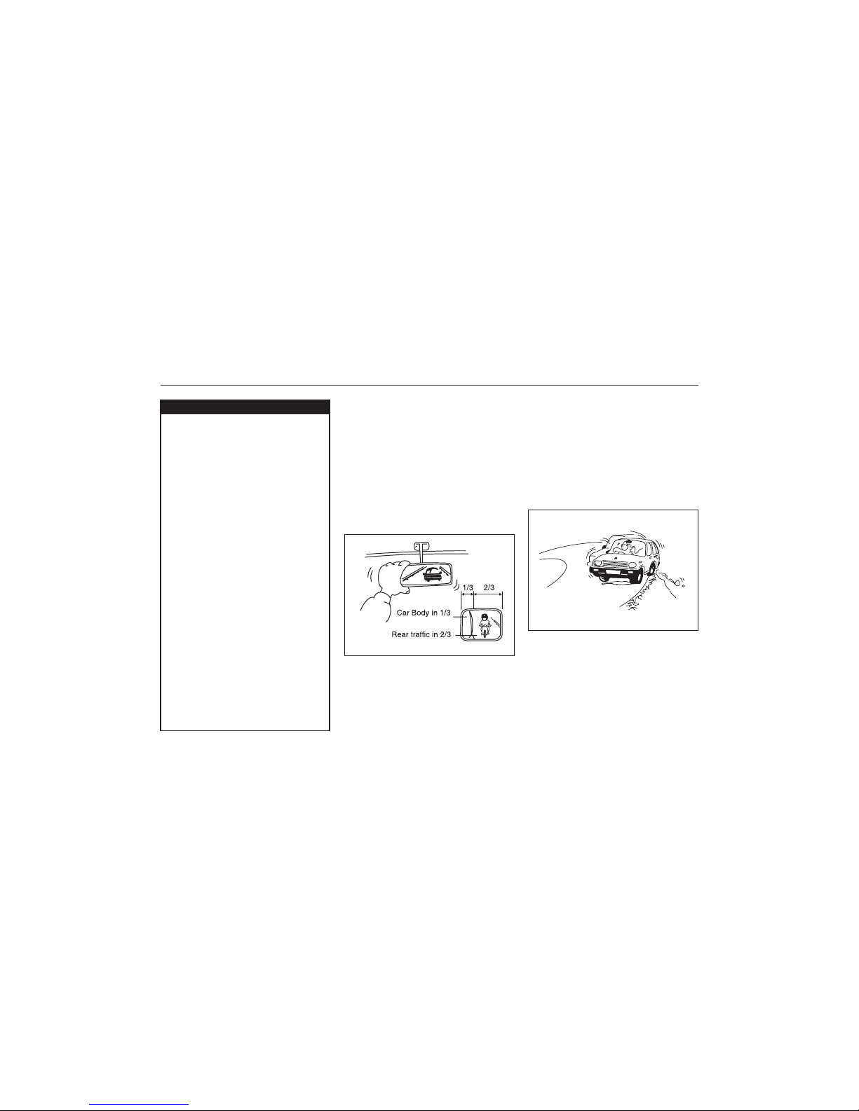
71
83K
Starting
1. Adjust the driver’s seat for the proper
driving posture.
2. Adjust the rear view mirror so as to
obtain the best possible rear view.
83K-04-008
83K-04-009
2. Always follow other vehicles at a safe
distance in order to prevent a rear-end
collision, should the vehicle ahead make
a sudden stop.
3. Turn ON the turn signal at least 30
meters before making a turn or changing
the lane so as not to be hit from behind.
DRIVING TIPS
6-5
DO’S AND DON’TS FOR SAFE
DRIVING
Exercise care in handling your vehicle. Be
conscious of not only your own safety but
also the safety of others on the road, and
thus enjoy the best and most comfortable
driving experience.
This section contains basic rules for safe
driving. Read it carefully for good
understanding of the content so that you
can enjoy safe and pleasant driving in your
Maruti Suzuki vehicle.
3. Before moving off, look forward and back
to confirm safety.
4. Don’t start quickly, for it is dangerous
and wastes fuel.
General driving
1. Be sure to stop before the stop light and
stop sign. When moving into the
intersection without any traffic lights or
signs, drive slowly to confirm safety.
ww
ww
w WARNING
In addition to following the driving tips
in this section, it is important to
observe the following precautions.
• Make sure your tyres are in good
condition and always maintain the
specified tyre pressure. Refer to
“Tyres” in the “INSPECTION AND
MAINTENANCE” section for details.
• Do not use tyres other than those
specified by MARUTI SUZUKI. Never
use different sizes or types of tyres on
the front and rear wheels. For
information regarding the specified
tyres, refer to the Tyre Information
Label located on the driver’s door pillar.
• Never use oversized tyres or special
shock absorbers and springs to raise
(jack up) your vehicle. This will
change the handling characteristics.
Oversized tyres may also rub against
the fender over bumps, causing
vehicle damage or tire failure.
• After driving through water, test the
brakes while driving at a slow speed
to see if they have maintained their
normal effectiveness. If the brakes
are less effective than normal, dry
them by repeatedly applying the
brakes while driving slowly until the
brakes have regained their normal
effectiveness.
Page 72

72
83K
DRIVING TIPS
6-6
83K-04-010
4. Before entering a corner, decelerate to
a safe speed. Don’t apply brakes during
cornering, or a cornering skid may occur.
5. When overtaking other vehicles, watch
out for the oncoming vehicle and
carefully confirm the safety.
6. Don’t attempt zigzag driving which will
hinder your control over the vehicle and
cause an accident.
Braking
1. Use the parking brake when parking
(1) Warn the vehicle behind you
(2) Gradually apply the brake.
(3) Bring the vehicle to a halt.
3. When driving on a downhill, try not to
apply the brake but use the engine brake
effectively. Overuse of the footbrake may
result in total brake failure.
4. Avoid reckless high speed driving and try
to drive at a safe speed suitable for the
road conditions while maintaining a
constant speed.
83K-04-012
83K-04-011
your vehicle and shift the gear shift lever
into the first gear or reverse gear
position for the sake of safety.
2. Don’t use handbraking unless unavoidable. It causes the vehicle to skid
and a rearend collision occur. It is
especially dangerous when the tyres are
worn, for they allow a larger skid.
Use foot brake in three stages
5. The higher the speed, the narrower the
driver’s visual range becomes. In such
a state, it is difficult to anticipate any
hazard and the driver feels much
fatigued.
6. Never do sharp handling during high
speed driving. You will lose your control
over your vehicle.
7. When overtaking or changing the lane
while driving at a high speed, keep an
ample vehicle-to-vehicle distance.
Long distance driving
1. Be sure to perform safety checks before
starting a trip.
2. Take rest at certain intervals to prevent
an accident which may occur when you
are sleepy or tired.
Page 73

73
83K
83K-04-014
83K-04-015
other drivers. For that, observe the
following.
• Drive at a safe speed.
• Maintain a sufficient distance between
your vehicle and the vehicle ahead.
• Don’t force yourself to overtake other
vehicles.
• Don’t make quick start, hard steering or
sudden stops.
• Allow an ample time in the driving
schedule.
• Observe traffic rules and regulations.
CONCLUSION
A perfect driver does not exist. The
endeavour of every motorist should be to
strive for perfection. Safety consciousness
not only ensures your safety and the safety
of other road users, it also helps reduce the
wear and tear on your vehicle, prolongs its
life, gives more mileage and ensures a
comfortable driving experience.
Follow the do’s and don’ts listed, and
driving will never be the same again.
MARGIN FOR SAFETY
It is important to allow yourself a margin for
safety during driving so that you can cope
with erroneous or unexpected driving of
DRIVING TIPS
6-7
83K-04-013
Night time driving
1. Drive more slowly at night than in the
daytime, for the visual range is restricted
at night.
2. Don’t overtake other vehicles at night.
Darkness bothers your sense of speed
and hinders your judgement on the
vehicle-to-vehicle distance.
3. Don’t use the high headlight beam
unless its use is inevitable. Its dazzle
may blitz the driver of the oncoming
vehicle, thus causing an accident.
4. Always keep the window glasses clean.
Don’t operate the windshield wiper when
the windshield glass is dry or the wiper
blade and glass may get damaged.
Page 74

74
83K
OTHER CONTROLS AND EQUIPMENT
Heating and Air Conditioning System ........................................................................... 7-1
Manual Heating and Air Conditioning System ............................................................. 7-1
Radio Antenna ..................................................................................................................... 7-4
Remote Audio Controls (if equipped) ............................................................................ 7-4
Fuel Filler Cap .................................................................................................................... 7-5
Engine Bonnet..................................................................................................................... 7-6
Sun Visor ............................................................................................................................. 7-6
Interior Light Switch .......................................................................................................... 7-7
Accessory Socket (if equipped) ...................................................................................... 7-7
Assist Grips (if equipped) ................................................................................................ 7-8
Glove Box ............................................................................................................................ 7-8
Instrument Panel Upper Tray ........................................................................................... 7- 8
Cup Holder ........................................................................................................................... 7-9
Front Seat Back Pocket (if equipped) ........................................................................... 7-9
Underseat Tray (if equipped) ........................................................................................... 7-9
Shopping Hook (if equipped) ......................................................................................... 7-10
Luggage Area Cover (if equipped) ............................................................................... 7-10
Frame Hooks ..................................................................................................................... 7-10
OTHER CONTROLS AND EQUIPMENT
Page 75

75
83K
Heating and Air Conditioning
System
The type of heating and air conditioning
system is:
• Manual Heating and Air Conditioning
System
Air Outlet
OTHER CONTROLS AND EQUIPMENT
7-1
83K-05-001
EXAMPLE
1. Windshield defroster outlet
2. Side defroster outlet
3. Side outlet
4. Center outlet
5. Front floor outlet
83K-05-002
When “Open”, air comes out regardless of
the air flow selector position.
Manual Heating and Air Conditioning System
Description of Controls
83K-05-003
Temperature selector (1)
This is used to select the temperature by
turning the selector.
Blower speed selector (2)
This is used to turn on the blower and to
select blower speed by turning the selector.
Air flow selector (3)
This is used to select one of the functions
described below.
Ventilation (a)
83K-05-005
Temperature-controlled air comes out of the
center and side air outlets.
83K-05-004
Page 76
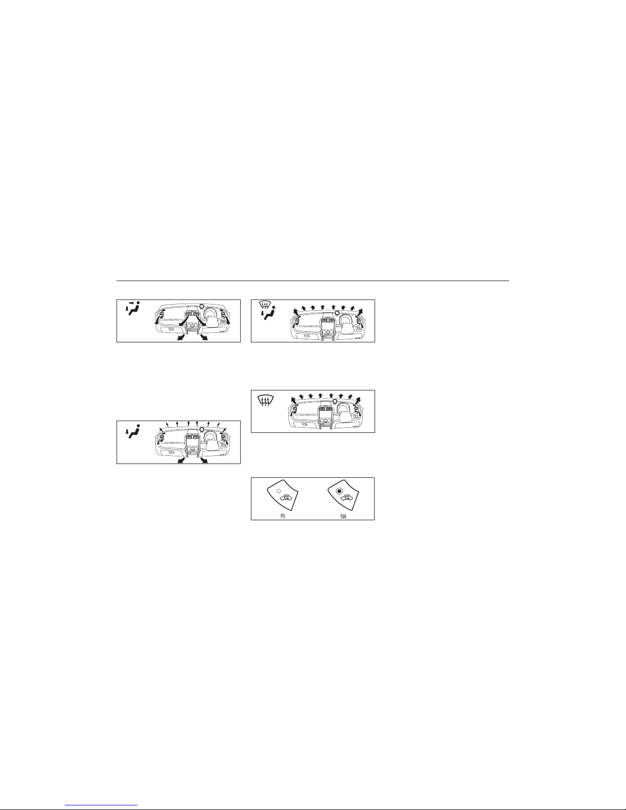
76
83K
OTHER CONTROLS AND EQUIPMENT
7-2
Bi-level (b)
83K-05-007
Temperature-controlled air comes out of the
floor outlets and the side outlets, also
comes out of the windscreen demister outlets and the side demister outlets slightly.
Heat & demist (d)
83K-05-006
Temperature-controlled air comes out of the
floor outlets and cooler air comes out of the
center and side outlets. When the
temperature selector (1) is in the fully COLD
position or fully HOT position, however, the
air from the floor outlets and the air from
the center and side outlets will be the same
temperature.
Heat (c)
Temperature-controlled air comes out of the
floor outlets, the windscreen demister
outlets, the side demister outlets and the
side outlets.
Defrost (e)
Air intake selector (4)
83K-05-008
Temperature-controlled air comes out of the
windscreen demister outlets, the side
demister outlets and the side outlets.
83K-05-009
83K-05-010
This selector is used to select the following
modes.
Fresh Air (f)
When this mode is selected, the indicator
light will go off and outside air is used.
Recirculated Air (g)
When this mode is selected, the indicator
light will come on, outside air is shut off and
inside air is recirculated. This mode is
suitable when driving through dusty or polluted air such as in a tunnel, or when
attempting to quickly cool down the interior.
“FRESH AIR” and “RECIRCULATED AIR”
are switched alternately each time the air
intake selector is pushed.
NOTE:
If you select “RECIRCULATED AIR” for an
extended period of time, the air in the vehicle can become contaminated. Therefore,
you should occasionally select “FRESH AIR”.
Air conditioning switch (5)
To turn on the air conditioning system, push
in the “A/C” switch and set the blower speed
selector to a position other than “OFF”. With
this “A/C” switch operation, a indicator light
will come on when the airconditioning system
is on. To turn off the air conditioning system,
push the “A/C” switch again.
During operation of the air conditioner, you
may notice slight changes in engine speed.
Page 77

77
83K
OTHER CONTROLS AND EQUIPMENT
7-3
These changes are normal, the system is
designed so that the compressor turns on
or off to maintain the desired temperature.
Less operation of the compressor results in
better fuel economy.
System Operating Instructions
Natural ventilation
Select “VENTILATION” and “FRESH AIR”,
the temperature selector to the desired
temperature position, and the blower speed
selector to “OFF”. Fresh air will flow through
the vehicle during driving.
Forced ventilation
The control settings are the same as for
natural ventilation except you set the blower
speed selector to a position other than “OFF”.
Normal heating (using outside air)
Select “HEAT” and “FRESH AIR”, the temperature selector to the desired temperature
position and the blower speed selector to
the desired blower speed position. Setting
the blower speed selector to a higher blower
speed position increases heating efficiency.
Quick heating (using recirculated air)
The control settings are the same as for
normal heating except you select “RECIRCULATED AIR”. If you use this heating
method for an extended period of time, the
air in the vehicle can become contaminated
and the windows can become misty.
Therefore, use this method only for quick
heating and change to the normal heating
method as soon as possible.
Cool face / Warm feet
Select “BI-LEVEL” and “FRESH AIR”, the
temperature selector to the desired temperature position, and the blower speed
selector to the desired blower speed position. Unless the temperature selector is in
the fully COLD position or fully HOT position, the air that comes out of the center
and side outlets will be cooler than the air
that comes out of the floor outlets.
Normal cooling
Turn on the “A/C” switch, set the air flow
selector to “VENTILATION”, the temperature
selector to the desired temperature position
and the blower speed selector to the
desired blower speed position. Setting the
blower speed selector to a higher blower
speed position increases cooling efficiency.
You can switch the air intake selector to
either “FRESH AIR” or “RECIRCULATED
AIR” as you desire. Choosing “RECIRCULATED AIR” increases cooling efficiency.
Quick cooling (using recirculated air)
The control settings are the same as for
normal cooling except you select “RECIRCULATED AIR” and the highest blower speed.
NOTE:
• If your vehicle has been left in the sun
with the windows closed, it will cool
faster if you open the windows briefly
while you operate the air conditioner with
the air intake selector at “FRESH AIR”
and the blower at high speed.
Dehumidifying
Turn on the “A/C” switch, set the air flow
selector to the desired air flow selector
position, and select “FRESH AIR”, the temperature selector to the desired temperature
position, and the blower speed selector to
the desired blower speed position.
83K-05-011
NOTE:
Because the air conditioner dehumidifies the
air, turning it on will help keep the windows
clear, even when blowing heated air using the
“DEMIST” or “HEAT & DEMIST” functions.
EXAMPLE
Page 78

78
83K
OTHER CONTROLS AND EQUIPMENT
7-4
Using the wrong refrigerant may
damage your air conditioning system.
Use R-134a only. Do not mix or replace
the R-134a with other refrigerants.
CAUTION
NOTE:
If you need maximum demisting:
• set the air flow selector to “DEMIST”,
• set the blower speed selector to HIGH,
• adjust the temperature selector to the
HOT end,
• turn on the “A/C” switch, and
• adjust the side outlets so the air blows
on the side windows.
Maintenance
If you do not use the air conditioner for a
long period, such as during winter, it may
not give the best performance when you
start using it again. To help maintain optimum performance and durability of your air
conditioner, it needs to be run periodically.
Operate the air conditioner at least once a
month for one minute with the engine idling.
This circulates the refrigerant and oil and
helps protect the internal components.
NOTE:
Your vehicle uses the air conditioning
refrigerant HFC-134a, commonly called “R134a”. Only R-134a should be used in your
vehicle.
Audio System (if equipped)
Refer supplementary manual for audio
system (if equipped), provided along with
the vehicle.
Radio Antenna
83K-05-013
To avoid damage to the radio antenna:
• Remove the antenna when using an
automatic car wash.
• Remove the antenna when the
antenna hits anything such as a low
ceiling in a parking garage or
putting a car cover over your car.
CAUTION
Remote Audio Controls
(if equipped)
83K-05-014
You can control basic functions of the audio
system with the switches on the steering
wheel.
To control the volume:
• To increase the volume, push the switch
(1).
• To decrease the volume, push the switch
(2).
• To mute, push the switch (3).
To select the mode, push the switch (4).
You can also turn on the audio system by
pushing the switch (4).
The radio antenna on the roof is removable.
To remove the antenna, turn it counterclockwise. To reinstall the antenna, turn
it clockwise firmly by hand.
Page 79

79
83K
OTHER CONTROLS AND EQUIPMENT
7-5
To change the radio station:
• To advance to the next preset station,
push the switch (5) briefly.
• To select the previous preset station,
push the switch (6) briefly.
• To scan the higher frequency radio station, push and hold the switch (5).
• To scan the lower frequency radio station, push and hold the switch (6).
To scan the selection on a CD:
• To advance to the next track on a CD,
push the switch (5).
• To select the previous track on a CD,
push the switch (6).
Fuel Filler Cap
83K-05-015
EXAMPLE
83K-05-016
ww
ww
w WARNING
Remove the fuel filler cap slowly. The
fuel may be under pressure and may
spray out, causing injury.
ww
ww
w WARNING
Petrol is extremely flammable. Do not
smoke when refueling, and make sure
there are no open flames or sparks in
the area.
EXAMPLE
83K-05-017
The fuel tank filler cap has a “screw-on
ratcheting type” feature.
• To remove, turn the cap counterclockwise. Turn the cap slowly to allow any
residual pressure to escape.
• To install, turn the cap clockwise and
tighten it securely until a “ratcheting”
(clicking) sound is heard. The “ratcheting” sound indicates that the cap is on
properly.
The fuel filler cap is located on the left rear
side of the vehicle. The fuel filler lid can be
unlocked by pulling up the opener lever
located on the outboard side of the driver’s
seat and locked by simply closing the lid.
If you need to replace the fuel cap,
use a MARUTI genuine cap. Use of an
improper cap can result in a malfunction of the fuel system or emission
control system. It may also result in
fuel leakage in the event of an accident.
ww
ww
w WARNING
Page 80

80
83K
OTHER CONTROLS AND EQUIPMENT
7-6
Engine Bonnet
To open the engine bonnet:
1) Pull the bonnet release handle located
on the outboard side of the driver’s side
of the instrument panel. This will disengage the engine bonnet lock halfway.
83K-05-018
EXAMPLE
83K-05-019
83K-05-020
2) Push the under-bonnet release lever up
with your finger, as shown in the illustration. While pushing the lever, lift up the
engine bonnet.
3) Continue to lift up the bonnet until it is
high enough to support with the prop
rod.
To close the engine bonnet:
1) Lift the bonnet up slightly and remove
the prop rod from the hole. Put the prop
rod back to the holding clip.
2) Lower the bonnet close to the bumper,
then let it drop down.
Make sure the bonnet is securely
latched after closing.
Make sure the bonnet is fully closed
and latched before driving. If it is not,
it can fly up unexpectedly during
driving, obstructing your view and
resulting in an accident.
ww
ww
w WARNING
83K-05-021
Sun Visor
The sun visors can be pulled down to block
glare coming through the windshield, or they
can be unhooked and turned to the side to
Page 81

81
83K
OTHER CONTROLS AND EQUIPMENT
7-7
CAUTION
When unhooking and hooking a sun
visor, be sure to handle it by the hard
plastic parts or the sun visor can be
damaged.
83K-05-022
Interior Light Switch
then fade out. If you insert the key into
the ignition switch during that time, the
light will start to fade out immediately.
After removing the key from the ignition
switch, the light will turn on for about 15
seconds and then fade out.
3) The light remains off even when the
door is opened.
83K-05-023
EXAMPLE
NOTE:
The number of doors involved in the lighting operation of the interior light depends
on the vehicle specification. If there is a
switch (rubber projection) at the door
opening as shown, the door is involved in
the lighting operation. The tailgate is also
involved in this operation even without the
rubber projection.
block glare coming through the side window.
This light switch has three positions which
function as described below:
1) The light comes on and stays on
regardless of whether the door is open
or closed.
2) The light comes on when the door is
opened.
After closing all doors, the light will
remain on for about 15 seconds and
Accessory Socket
(if equipped)
83K-05-024
CAUTION
Use of inappropriate electrical accessories can cause damage to your
vehicle’s electrical system. Make sure
that any electrical accessories you use
are designed to plug into this type of
socket.
The accessory socket will work when the
ignition switch is in the “ACC” or “ON” position. This socket can be used to provide 12
volt/120 watt power for electrical accessories.
Page 82

82
83K
OTHER CONTROLS AND EQUIPMENT
7-8
Assist Grips (if equipped)
83K-05-027
Assist grips are provided for passengers
convenience.
CAUTION
To avoid damaging the assist grip and
the molded headlining, do not hang
down the assist grip.
• Assist grip is not provided above
driver’s seat.
Glove Box
83K-05-028
ww
ww
w WARNING
Never drive with the glove box lid
open. It could cause injury if an accident occurs.
To open the glove box, pull the latch lever.
To close it, push the lid until it latches
securely.
Instrument Panel Upper Tray
83K-05-029
EXAMPLE
To use the instrument panel upper tray, lift
the front edge (1) and open the lid. To close
the lid, push the front edge (1). Do not put
heavy or sharp items in the upper tray.
ww
ww
w WARNING
Never drive with the instrument panel
upper tray lid open. It could cause
injury if an accident occurs.
CAUTION
If you park your vehicle outdoors in
direct sunlight or in hot weather, the
instrument panel upper tray can get
very hot. So, when parking in such
conditions:
• Do not leave eyeglasses in the
upper tray. The heat may distort
plastic lenses or frames.
• Do not leave CDs, CD cases, and
other plastic items in the upper tray.
The heat may distort them.
• Do not place flammable items, such
as a lighter, in the upper tray. The
heat may cause a fire.
Page 83

83
83K
OTHER CONTROLS AND EQUIPMENT
7-9
Cup Holder
The cup holder is provided in the center
console.
83K-05-030
EXAMPLE
ww
ww
w WARNING
Do not use the cup holder to hold cups
containing hot liquids, or sharp-edged,
hard or breakable objects. Objects in
the cup holder may be thrown about
during a sudden stop or impact, and
could cause personal injury.
Front Seat Back Pocket
(if equipped)
This pocket is provided for holding light and
soft things such as gloves, newspapers or
magazines.
83K-05-031
EXAMPLE
ww
ww
w WARNING
Do not put hard or breakable objects
in the pocket. If an accident occurs,
objects such as bottles, cans, etc. can
injure the occupants in the rear seat.
The tray is located under the front passenger’s seat. Pull the handle forward to draw
out the tray. Be sure to push back in the
tray before driving.
Underseat Tray (if equipped)
83K-05-032
EXAMPLE
Page 84
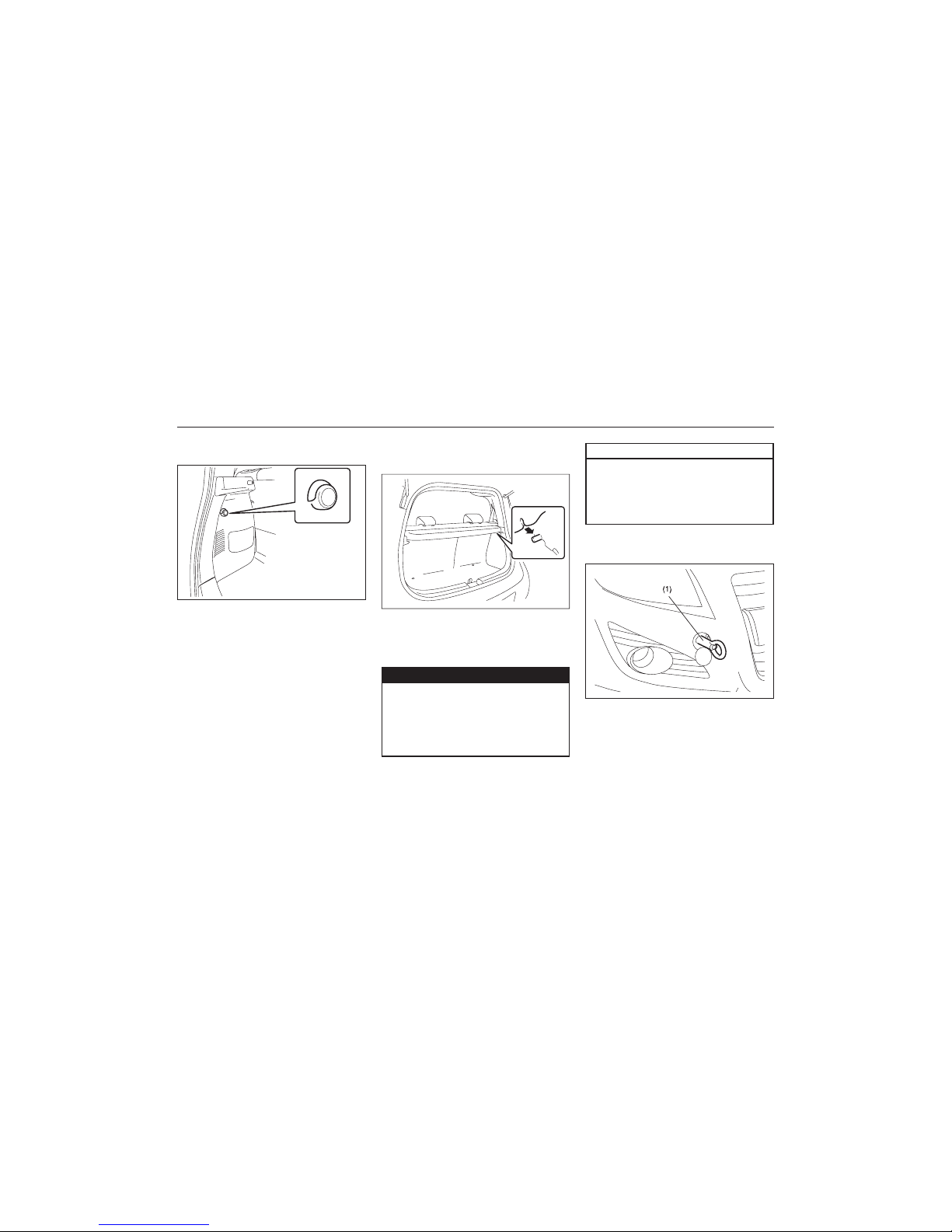
84
83K
OTHER CONTROLS AND EQUIPMENT
7-10
Luggage Area Cover
(if equipped)
Luggage or other cargo placed in the luggage compartment are hidden from view by
a luggage area cover.
83K-05-034
EXAMPLE
ww
ww
w WARNING
Do not carry items on top of the luggage area cover, even if they are
small and light. Objects on top of the
cover could be thrown about in an
accident, causing injury, or could
obstruct the driver’s rear view.
Shopping Hook (if equipped)
83K-05-033
EXAMPLE
The shopping hooks are located on the both
sides of the luggage compartment.
You can hang the shopping bag or other
suitable objects on the hook. This hook is
not designed for large or heavy items.
Frame Hooks
Front
The towing hook (1) is provided on the front
of the vehicle for use in emergency situations.
To install the hook (1), follow the procedure
below.
CAUTION
To avoid damaging the luggage area
cover:
• Do not push down on it or lean on it.
• Handle it carefully when installing or
removing.
83K-05-035
Page 85
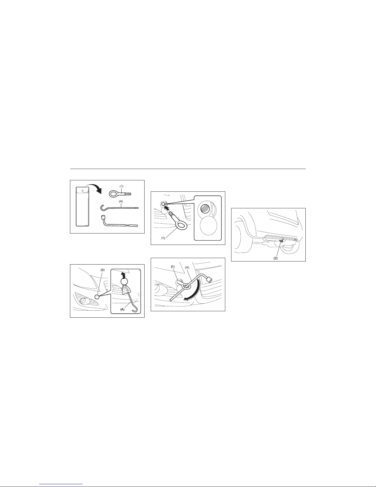
85
83K
OTHER CONTROLS AND EQUIPMENT
7-11
(with spare tyre)
83K-05-036
83K-05-037
1) Pick up the towing hook (1) and jack
handle (A). The towing hook and jack
handle in the storage bag are stowed
just under the spare tyre in the luggage
compartment.
2) Remove the cover (B) by using a jack
handle (A) covered with a soft cloth as
shown in the illustration.
83K-05-038
3) Install the towing hook (1) by hand.
83K-05-039
To remove the towing hook (1), reverse the
procedure used to install the towing hook.
Rear
83K-05-040
The frame hook (2) is provided on the rear
of the vehicle for use in emergency situations.
To tow your vehicle on the road or highway,
follow the instruction of “Towing” in “EMERGENCY SERVICE” or “VEHICLE LOADING
AND TOWING” section.
EXAMPLE
4) To tighten the towing hook (1), turn it
clockwise by using a jack handle (A)
until the hook (1) is securely installed.
Page 86

86
83K
OTHER CONTROLS AND EQUIPMENT
7-12
Do not use the hooks (1) and (2) to
tow (or be towed by) another vehicle
on the road or highway. These hooks
are designed for use in emergency
situations and sea shipping purposes
only.
ww
ww
w WARNING
83K-05-041
EXAMPLE
The hooks (3) and frame holes (4) (if
equipped) are provided for shipping purposes only.
EXAMPLE
83K-05-042
Page 87

87
83K
VEHICLE LOADING AND TOWING
VEHICLE LOADING AND TOWING
Vehicle Loading
Your vehicle was designed for specific weight
capacities. The weight capacities of your
vehicle are indicated by the Gross Vehicle
Weight Rating (GVWR) and the Gross Axle
Weight Rating (GAWR, front and rear). The
GVWR and GAWR (front and rear) are listed
in the “SPECIFICATIONS” section.
GVWR – Maximum permissible overall weight
of the fully loaded vehicle (including all the
occupants, accessories and cargo plus the
trailer nose weight if towing a trailer).
GAWR – (Front and Rear) Maximum permissible weight on an individual axle.
Actual weight of the loaded vehicle and actual
loads at the front and rear axles can only be
determined by weighing the vehicle. Compare
these weights to the GVWR and GAWR (front
and rear). If the gross vehicle weight or the
load on either axle exceeds these ratings, you
must remove enough weight to bring the load
down to the rated capacity.
ww
ww
w WARNING
Always distribute cargo evenly. To
avoid personal injury or damage to your
vehicle, always secure cargo to prevent
it from shifting if the vehicle moves
suddenly. Place heavier objects on the
floor and as far forward in the cargo
area as possible. Never pile cargo
higher than the top of the seat backs.
ww
ww
w WARNING
Never overload your vehicle. The gross
vehicle weight (sum of the weights of
the vehicle, all the occupants,
accessories, cargo plus trailer nose
VV
VV
V
ww
ww
w WARNING
VV
VV
V
weight if towing a trailer) must never
exceed the Gross Vehicle Weight
Rating (GVWR). In addition, never
distribute a load so that the weight on
either the front or rear axle exceeds
the Gross Axle Weight Rating (GAWR).
Trailer Towing
Your MARUTI SUZUKI was originally
designed to carry people and a normal
amount of cargo, not to tow a trailer. MARUTI
SUZUKI does not recommend you use your
vehicle to tow a trailer if there is not any local
regulation about towing capacity permitted (for
example, registered or statutory towing
capacity). Towing a trailer can adversely affect
handling, durability, and fuel economy.
When you tow your vehicle, follow the
instructions below to avoid accidents
and damage to your vehicle. In addition,
be sure to observe government and
local requirements regarding vehicle
lighting and trailer hitches or tow bars.
ww
ww
w WARNING
Towing Your Vehicle
Your vehicle may be towed behind another
Vehicle (such as a motorhome), provided
you use the proper towing method specified
for your vehicle. The towing method you
must use depends on the specifications of
your vehicle: whether it is a manual
transmission vehicle or an automatic
transmission vehicle.
Use the towing instruction table to select the
proper towing method for your vehicle, and
carefully follow the corresponding
instructions. Be sure to use proper towing
equipment designed for recreational towing
and make sure that towing speed does not
exceed 90 km/h.
ww
ww
w WARNING
A safety chain should always be used
when you tow your vehicle.
8-1
Page 88

88
83K
VEHICLE LOADING AND TOWING
TOWING INSTRUCTION TABLE
DRIVE TRANSAXLE TOWING
TRAIN METHOD
2WD
A/T
(AUTO)
M/T
(MANUAL)
A
A B
Towing an automatic transaxle vehicle
with four wheels on the ground can
result in damage to the automatic
transaxle.
83K-06-001
NOTICE
A: 2WD VEHICLES WITH MANUAL
TRANSAXLE OR AUTOMATIC
TRANSAXLE
1) Secure the front wheels on a towing
dolly according to the instructions
provided by the dolly manufacturer.
2) Release the parking brake.
83K-06-002
TOWING METHOD A
FROM THE FRONT:
FRONT WHEELS ON A DOLLY
AND REAR WHEELS ON THE GROUND
B: 2WD VEHICLES WITH MANUAL
TRANSAXLE
1) Shift the manual transaxle lever into
neutral.
2) Turn the ignition key to the “ACC”
position to unlock the steering wheel.
3) Release the parking brake.
83K-06-003
TOWING METHOD B
FROM THE FRONT:
FOUR WHEELS ON THE GROUND
NOTICE
The steering column is not strong
enough to withstand shocks
transmitted from the front wheels
during towing. Always unlock the
steering wheel before towing.
8-2
Page 89

89
83K
INSPECTION AND MAINTENANCE
Maintenance Schedule ....................................................................................................... 9-1
Drive Belt ............................................................................................................................. 9-6
Engine Oil and Filter ......................................................................................................... 9-6
Engine Coolant.................................................................................................................... 9-9
Air Cleaner ......................................................................................................................... 9-11
Spark Plugs ....................................................................................................................... 9-11
Gear Oil .............................................................................................................................. 9-13
Clutch Pedal ...................................................................................................................... 9-14
Fuel Filter (Diesel engine) .............................................................................................. 9-14
Brakes ................................................................................................................................. 9-15
Steering .............................................................................................................................. 9-16
Tyres ................................................................................................................................... 9-17
Battery ................................................................................................................................ 9-19
Fuses ................................................................................................................................... 9-20
Bulb Replacement............................................................................................................. 9-23
Wiper Blades ..................................................................................................................... 9-26
Windshield Washer Fluid ................................................................................................ 9-28
Air Conditioning System ................................................................................................. 9-29
INSPECTION AND MAINTENANCE
Page 90

90
83K
You should take extreme care when
working on your vehicle to prevent
accidental injury. Here are a few precautions that you should be especially
careful to observe:
• To prevent damage or unintended
activation of the air bag system be
sure the battery is disconnected and
the ignition switch has been in the
“LOCK” position for at least 90
seconds before performing any
electrical service work on your
vehicle. Do not touch air bag system components and wires. The
wires are wrapped with yellow tape
or yellow tubing, and the couplers
are yellow for easy identification.
ww
ww
w WARNING
83K-07-001
ww
ww
w WARNING
ww
ww
w WARNING
INSPECTION AND MAINTENANCE
9-1
VV
VV
V
• Do not leave the engine running in
garages or other confined areas.
• When the engine is running, keep
hands, clothing, tools, and other
objects away from the fan and drive
belt. Even though the fan may not
be moving, it can automatically turn
on without warning.
• When it is necessary to do service
work with the engine running, make
sure that the parking brake is
applied fully and the transmission is
in Neutral.
• Do not touch ignition wires or other
ignition system parts when starting
the engine or when the engine is
running, or you could receive an
electric shock.
• Be careful not to touch a hot
engine, exhaust manifold and pipes,
muffler, radiator and water hoses.
• Do not allow smoking, sparks, or
flames around petrol or the battery.
Flammable fumes are present.
• Do not get under your vehicle if it
is supported only with the portable
jack provided in your vehicle.
VV
VV
V
VV
VV
V
• Be careful not to cause accidental
short circuits between the positive
and negative battery terminals.
• Keep used oil, coolant, and other
fluids away from children and pets.
Dispose of used fluids properly;
never pour them on the ground, into
sewers, etc.
VV
VV
V
83K-07-002
Maintenance Schedule
The following table shows the times when
you should perform regular maintenance on
your vehicle. This table shows in kilometers
and months when you should perform
inspections, adjustments, lubrication and
other services.
EXAMPLE
Page 91

91
83K
INSPECTION AND MAINTENANCE
9-2
ww
ww
w WARNING
MARUTI SUZUKI recommends that
maintenance on your MARUTI SUZUKI
vehicle should be performed by
MARUTI SUZUKI authorised Dealer/
Service Station.
CAUTION
Whenever it becomes necessary to
replace parts on your vehicle, it is
recommended that you use MARUTI
GENUINE PARTS (MGP) only.
Periodic Maintenance Schedule
“A” : Adjust
“C” : Clean
“R” : Replace or Change
“I” : Inspect, correct or replace if
necessary
“L” : Lubricate
“T” : Tighten to Specified Torque
“O” : Rotate
NOTE:
This table includes services as scheduled
up to 80,000 km mileage. Beyond 80,000
km, carry out the same services at the
same intervals respectively.
Page 92

92
83K
FREE INSPECTION PERIODIC MAINTENANCE AT COST
Interval: This interval should be judged by odometer km (x1000) 1 5 10 20 30 40 50 60 70 80
reading or months, whichever comes first. months 1 6 12 24 36 48 60 72 84 96
ENGINE
1-1. Water pump drive belt (Tension, Wear) Petrol -----I---R
1-2. Engine Coolant (Level, Leakage) I I I R I R I R I R
1-3. Engine oil and engine oil filter - - R R RRRRRR
1-4. Cooling system hoses and connections (Leakage and Damage) IIIIIIIIII
1-5. Engine bolts (All cylinder head and manifold fixings) - - T - T - T - T -
1-6. Engine Mounting (All cylinder head and manifold fixings) - - T - T - T - T -
1-7. Valve Cleanrance Petrol ----I--I--
1-8. Exhaust System (Noise, Leakage etc.) - I - I -----I
1-9. Positive Crank Case Ventilation System
(Hoses, Connections and Valve)
-I-I----- I
1-10. Exhaust Gas Recirculation Valve Diesel ----C--C--
IGNITION
2-1. Ignition wiring (Damage, Deterioration) - - - I - I - I - I
2-2. Spark Plug (Clean and adjust the gap) Petrol -----R---R
FUEL
3-1. Air cleaner filter element Paved-road Petrol Clean after every 5,000 KM. Replace after every 40,000KM
Diesel Replace after every 20,000 KM. Cleaning not required
Dusty Condition Petrol Clean after every 2,500 KM. or as rquired. Replace after every 40,000KM
Diesel Replace after every 20,000 KM. Cleaning not required.
More frequent replacement if dust condition is severe.
3-2.
Fuel tank cap, fuel lines and connections (Leakage and Damage)
-I---I--- I
3-3. Fuel Filter (Leakage) Petrol -----R---R
3-4. Fuel Filter and Water Draining Diesel I I I R I R I R I R
INSPECTION AND MAINTENANCE
9-3
Page 93

93
83K
FREE INSPECTION PERIODIC MAINTENANCE AT COST
Interval: This interval should be judged by odometer km (x1000) 1 5 10 20 30 40 50 60 70 80
reading or months, whichever comes first. months 1 6 12 24 36 48 60 72 84 96
CLUTCH AND TRANSMISSION
4-1. Clutc h Pedal (Play) Petrol IIIIIIIIII
4-2. Clutch Fluid (Level, Leakage) Diesel I I I R I R I R I R
4-3. Clutc h Slipping (D ragging or Excess Damage) IIIIIIIIII
4-4.
Manual Transmission/Transfer or Differential Oil (Level, Leakage)
I I IRIRIRIR
4.5. Automatic transmission Fluid (Level, Leakage) Replace at 1,65,000 KM or 11 years whichever comes first
4.6. Hose, Automatic transmission fluid IIIIIIIIII
DRIVE SHAFT
5-1. Drive shaft boot (boot damage) - IIIIIIIII
BRAKE
6-1. Brake Fluid (Level, Leakage) I I I R I R I R I R
6-2. Brake Pedal (pedal - wall clearance) IIIIIIIIII
6-3. Parking brake lever and cable (Play, damage) IIIIIIIIII
6-4. Brake disc and pad (Wear) - IIIIIIIII
6-5. Brake drum and shoes (Wear) - - IIIIIIII
6-6. Master cylinder/wheel cylinder/caliper (Oil leakage, boot cut)
IIIIIRIIIR
(replace piston and boot kits)
6-7. Brake hoses and pipes (Leakage, damage) IIIIIIIIII
WHEEL
7-1. Tyres (air pressure, abnormal wear, crack and rotation) I I&O I&O I&O I&O I&O I&O I&O I&O I&O
7-2. Wheels (Damage) IIIIIIIIII
7-3. Front/Rear wheel bearing (Loose, damage) IIIIIIIIII
FRONT / REAR SUSPENSION
8-1. Suspension strut (Oil leakage, damage) IIIIIIIIII
8-2. Suspension arms / Knuckle support (Loose, damage) - IIIIIIIII
8-3. Rear spring (Damage) IIIIIIIIII
8-4. Shock absorbers (Oil leakage, damage) IIIIIIIIII
8-5. All bolts and nuts (Loose) - TTTTTT TTT
8-6. Suspension arms and torsion rods - IIIIIIIII
INSPECTION AND MAINTENANCE
9-4
Page 94

94
83K
FREE INSPECTION PERIODIC MAINTENANCE AT COST
Interval: This interval should be judged by odometer km (x1000) 1 5 10 20 30 40 50 60 70 80
reading or months, whichever comes first. months 1 6 12 24 36 48 60 72 84 96
STEERING
9-1. Steering wheel (Play, loose) IIIIIIIIII
9-2. All ro ds and arms (Loose, damage, wear) IIIIIIIIII
ELECTRICAL
10-1. Battery electrolyte (Level, leakage) IIIIIIIIII
10-2. Wiring harness connection (Loose, damage) - IIIIIIIII
10-3. Lig htening system (Operation, stains, damage) IIIIIIIIII
10-4. Horn (Operation) IIIIIIIIII
10-5. System Voltage - IIIIIIIII
BODY
11-1. All chassis bolts and nuts (Tighten) - I TTTTT TTT
11-2. All latches, hinges and locks (Function) I I&L I&L I&L I&L I&L I&L I&L I&L I&L
ROAD TEST
12-1. Operation of Brakes, gear shifting and speedometer IIIIIIIIII
12-2. Body and chassis noise IIIIIIIIII
AIR CONDITIONER (if equipped)
13-1. Check belt tension IIIIIIIIII
13-2. Tighten compressor mounting bolt - TTTTTT TTT
13-3. All hose joint (Check, tighten) IIIIIIIIII
13-4. Check functioning of Recirc flap IIIIIIIIII
13-5. Clean condensor with low pressure water - C C C CCCCCC
13-6. Check belt for frayed edges IIIIIIIIII
13-7. Check all mounting bolts IIIIIIIIII
INSPECTION AND MAINTENANCE
9-5
Page 95

95
83K
Drive Belt
ww
ww
w WARNING
When the engine is running, keep
hands, hair, clothing, tools, etc. away
from the moving fan and drive belts.
(For Petrol Engine Model)
Make sure the drive belt tension is correct.
If the belt is too loose, insufficient battery
charging, engine overheating, poor power
steering, poor air conditioning, or excessive
belt wear can result. When you press the
belt with your thumb midway between the
pulleys, there should be a deflection
according to the following chart.
The belts should also be examined to
ensure that they are not damaged.
If you need to replace or adjust the belt
have it done by your MARUTI SUZUKI
dealer.
(For Diesel Engine Model)
The drive belts tension is adjusted automatically.
Engine Oil and Filter
Specified Oil
(For Petrol Engine Model)
(1) Preferred
→: 100 N (10 kg, 22 lbs) press GE: Generator
DEF: Deflection AC: Air conditioner compressor
INSPECTION AND MAINTENANCE
9-6
83K-07-003
(For Diesel Engine Model)
83K-07-005
Be sure that the engine oil you use comes
under the quality classification of ACEA B3.
Select the appropriate oil viscosity according
to the above chart.
The recommended Engine Oil is CG
5W-40, API -CG4 or above.
Oil Level Check
(For Petrol Engine Model)
83K-07-006
(1) Preferred
83K-07-005
Be sure that the engine oil you use comes
under the quality classification of SG+.
The recommended Engine Oil is SG+
5W-30.
Page 96
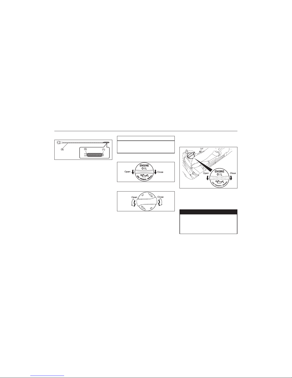
96
83K
INSPECTION AND MAINTENANCE
9-7
(For Diesel Engine Model)
83K-07-007
CAUTION
Failure to check the oil level regularly
could lead to serious engine trouble
due to insufficient oil.
(1) MIN
(2) MAX
(3) Engine oil dipstick
It is important to keep the engine oil at the
correct level for proper lubrication of your
vehicle’s engine. Check the oil level with the
vehicle on a level surface. The oil level
indication may be inaccurate if the vehicle
is on a slope. The oil level should be
checked either before starting the engine or
at least 5 minutes after stopping the engine.
The handle of the engine oil dipstick is colored yellow for easy identification. Pull out
the oil dipstick, wipe oil off with a clean cloth,
insert the dipstick all the way into the engine,
then remove it again. The oil on the stick
should be between the upper and lower
limits shown on the stick. If the oil level
indication is near the lower limit, add enough
oil to raise the level to the upper limit.
83K-07-008
83K-07-009
Refilling (Petrol)
Refilling (Diesel)
Remove the oil filler cap and pour oil slowly
through the filler hole to bring the oil level
to the upper limit on the dipstick. Be careful
not to overfill. Too much oil is almost as
bad as too little oil. After refilling, start the
engine and allow it to idle for about a
minute. Stop the engine, wait about 5 minutes and check the oil level again.
Changing Engine Oil and Filter
Drain the engine oil while the engine is still
warm.
83K-07-010
The engine oil temperature may be
high enough to burn your fingers
when the drain plug is loosened. Wait
until the drain plug is cool enough to
touch with your bare hands.
ww
ww
w WARNING
1) Remove the oil filler cap.
2) Place a drain pan under the drain plug.
3) Using a wrench, remove the drain plug
and drain out the engine oil.
Page 97

97
83K
INSPECTION AND MAINTENANCE
9-8
83K-07-011
EXAMPLE
For Petrol
For Diesel
EXAMPLE
Tightening torque for drain plug (1):
• Petrol Engine
35 Nm (3.5 kg-m, 25.5 lb-ft)
• Diesel Engine
20 Nm (2.0 kg-m, 14.5 lb-ft)
NOTE:
Washer (2) should be replaced every time
when opened.
ww
ww
w WARNING
New and used oil can be hazardous.
Children and pets may be harmed by
swallowing new or used oil. Keep new,
used oil and used oil filters away from
children and pets.
Continuous contact with used engine
oil may cause (skin) cancer.
Brief contact with used oil may irritate
skin.
To minimize your exposure to used
oil, wear a long-sleeve shirt and
moisture-proof gloves (such as dishwashing gloves) when changing oil. If
oil contacts your skin, wash thoroughly with soap and water.
Launder any clothing or rags if wet
with oil.
Recycle or properly dispose of used
oil and filters.
4) Reinstall the drain plug and gasket.
Tighten the plug with a wrench to the
specified torque.
Replace the Oil Filter
1) Using an oil filter wrench, turn the oil filter counterclockwise and remove it.
2) Using a clean rag, wipe off the mounting surface on the engine where the new
filter will be seated.
3) Smear a little engine oil around the rubber gasket of the new oil filter.
4) Screw on the new filter by hand until the
filter gasket contacts the mounting surface.
(For Petrol Engine Model)
83K-07-012
83K-07-013
(1) Loosen
(2) Tighten
Tightening (viewed from filter top)
83K-07-014
(1) Oil filter
(2) 3/4 turn
Page 98

98
83K
INSPECTION AND MAINTENANCE
9-9
(For Diesel Engine Model)
83K-07-015
CAUTION
To tighten the oil filter properly, it is
Important to accurately identify the
position at which the filter gasket first
contacts the mounting surface.
CAUTION
To prevent oil leakage, make sure that
the oil filter is tight, but do not overtighten it.
(1) Loosen
(2) Tighten
NOTE:
Replace ring along with the new filter never
use the old ring in the new filter.
5) Tighten the filter specified turn from the
point of contact with the mounting surface (or to the specified torque) using an
oil filter wrench.
Tightening torque for oil filter
• Petrol Engine
3/4 turn or
14 Nm (1.4 kg-m, 10.5 lb-ft)
• Diesel Engine
3/4 turn or
25 Nm (2.5 kg-m, 18.1 lb-ft)
Refill with Oil and Check for Leaks
1) Pour oil through the filler hole and install
the filler cap.
For the approximate capacity of the oil,
refer to the “CAPACITIES” item in the
“SPECIFICATIONS” section.
2) Start the engine and look carefully for
leaks at the oil filter and drain plug. Run
the engine at various speeds for at least
5 minutes.
3) Stop the engine and wait about 5 minutes. Check the oil level again and add
oil if necessary. Check for leaks again.
CAUTION
• When replacing the oil filter, it is
recommended that you use a
MARUTI genuine replacement filter.
VV
VV
V
CAUTION
VV
VV
V
• Oil leaks from around the oil filter or
drain plug indicate incorrect installation or gasket damage. If you find
any leaks or are not sure that the
filter has been properly tightened,
have the vehicle inspected by your
MARUTI SUZUKI dealer.
Engine Coolant
(For Petrol Engine Model)
83K-07-016
EXAMPLE
EXAMPLE
83K-07-017
Page 99
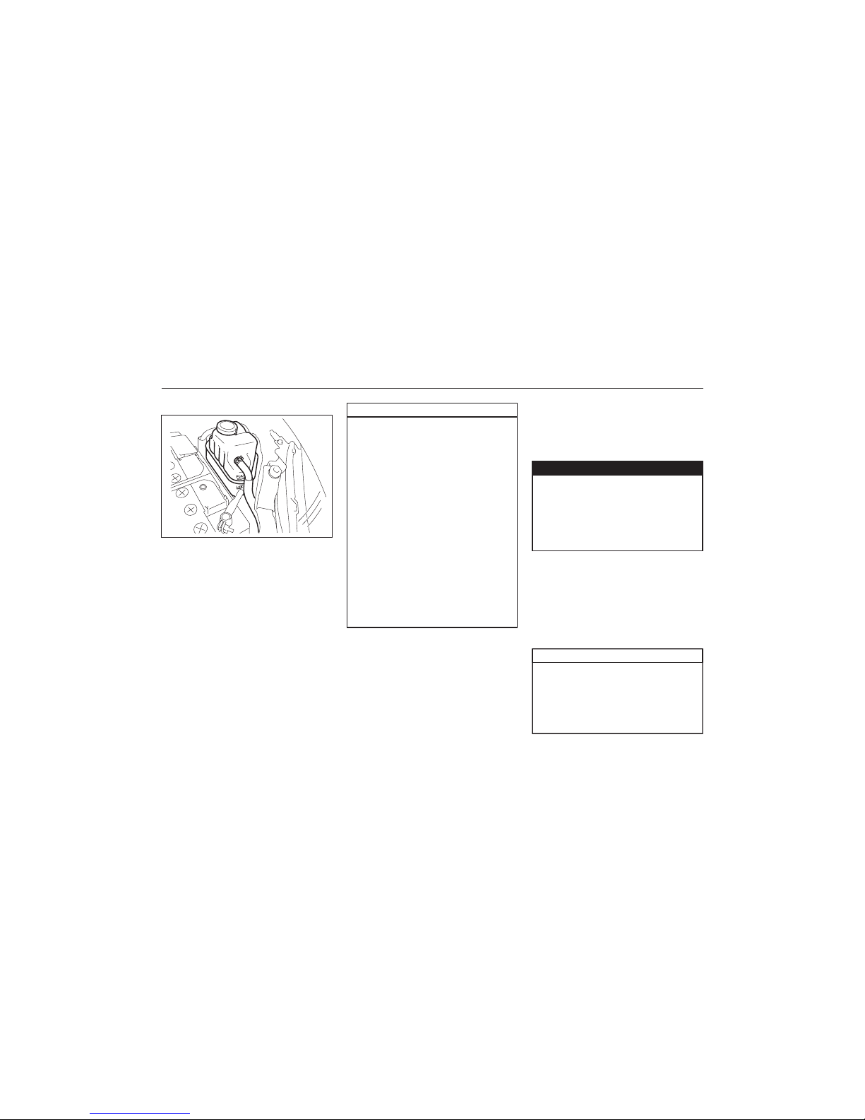
99
83K
INSPECTION AND MAINTENANCE
9-10
(For Diesel Engine Model)
83K-07-018
CAUTION
To avoid damaging your cooling system:
• Always use a high quality ethylene
glycol base non-silicate based
coolant diluted with distilled water
at the correct mixture concentration.
• Make sure that the proper mix is 50/
50 coolant to distilled water (Diesel)
and 30/70 (For petrol). Concentrations other than this may cause
overheating conditions.
• Neither use 100% coolant nor 100%
plain water.
• Do not add extra inhibitors or additives. They may not be compatible
with your cooling system.
• Do not mix different types of base
coolants. Doing so may result in
accelerated seal wear and/or the
possibility of severe overheating and
extensive engine damage.
Coolant Level Check
Check the coolant level at the reservoir
tank, not at the radiator. With the engine
cool, the coolant level should be between
the “FULL” and “LOW” marks.
Selection of Coolant
To maintain optimum performance and
durability of your engine, use MARUTI
Genuine Coolant or equivalent.
This type of coolant is best for your cooling
system as it:
• Helps maintain proper engine temperature.
• Gives proper protection against freezing
and boiling.
• Gives proper protection against corrosion
and rust.
Failure to use the proper coolant can damage your cooling system. Your MARUTI
SUZUKI authorized dealer can help you
select the proper coolant.
ww
ww
w WARNING
It is hazardous to remove the reservoir
tank cap (degassing tank cap) for Diesel
engine when the water temperature is
high, because scalding fluid and steam
may be blown out under pressure. Wait
until the coolant temperature has
lowered before removing the cap.
Adding Coolant
(For Petrol Engine Model)
If the coolant level is below the “LOW”
mark, more coolant should be added.
Remove the reservoir tank cap and add
coolant until the reservoir tank level reaches
the “FULL” mark. Never fill the reservoir
tank above the “FULL” mark.
(For Diesel Engine Model)
If the coolant level is below the “LOW”
mark, more coolant should be added. When
the engine is cool, remove the degassing
tank cap by turning it anticlockwise slowly
to release any pressure. And add coolant
until the degassing tank level reaches the
“FULL” mark. Never fill the degassing tank
above the “FULL” mark.
• The mixture you use should contain
50% concentration of antifreeze.
• If the lowest ambient temperature in
your area is expected to be – 35°C
(–31°F) or below, use higher
concentrations up to 60% following
CAUTION
VV
VV
V
Page 100

100
83K
INSPECTION AND MAINTENANCE
9-11
CAUTION
the instructions on the antifreeze
container.
• When putting the cap on the reservoir tank, line up the arrow on the
cap and the arrow on the tank. Failure to follow this can result in coolant leakage.
Engine coolant is harmful or fatal if
swallowed or inhaled. Do not drink
antifreeze or coolant solution. If swallowed, do not induce vomiting. Immediately contact a poison control center
or a physician. Avoid inhaling mist or
hot vapors; if inhaled, remove to fresh
air. If coolant gets in eyes, flush eyes
with water and seek medical attention.
Wash thoroughly after handling.
Solution can be poisonous to animals.
Keep out of the reach of children and
animals.
ww
ww
w WARNING
VV
VV
V
Coolant Replacement
Coolant Replacement work requires technical skill. Do not replace the coolant by
yourself. Trust this job to Maruti Suzuki
authorised Dealer Workshop or Service
Station.
Air Cleaner
(For Petrol Engine Model)
83K-07-019
83K-07-020
(For Diesel Engine Model)
If the air cleaner is clogged with dust, there
will be greater intake resistance, resulting
in decreased power output and increased
fuel consumption.
Unclamp the side clamps or loosen the
screws, and remove the element from the
air cleaner case. If it appears to be dirty,
replace it with a new one.
Spark Plugs
83K-07-021
 Loading...