

Suzuki AN650/A Supplementary Service Manual
AN650
USE THIS MANUAL WITH:
AN650 SERVICE MANUAL (99500-36113-01E)
/
A
99501-36160-01E
AN650/AK7 (’07-MODEL) 1
AN650/AK7 (’07-MODEL)
This manual describes service data, service specifications, FI and servicing procedures which
differ from those of the AN650/AK6 (’06-model).
NOTE:
• Any differences between the AN650/AK6 (’06-model) and AN650/AK7 (’07-model) in
specifications and service data are indicated with an asterisk mark (*).
• Please refer to the AN650K6 (’06-model) service manual for details which are not given
in this manual.
CONTENTS
SPECIFICATIONS (AN650K7)........................................................................... 3
SPECIFICATIONS (AN650AK7) ........................................................................ 5
SDS CHECK ....................................................................................................... 7
FI SYSTEM WIRING DIAGRAM......................................................................... 11
ECM/PCM TERMINAL........................................................................................ 12
FAIL-SAFE FUNCTION............................................................................. 14
MALFUNCTION CODE AND DEFECTIVE CONDITION .......................... 15
“C40” (P0505 or P0506 and P0507) ISC VALVE CIRCUIT
MALFUNCTION......................................................................................... 16
“C41” (P2505) ECM/PCM POWER INPUT CIRCUIT
MALFUNCTION......................................................................................... 21
“C44” (P0130/P0135) HO2 SENSOR (HO2S) CIRCUIT
MALFUNCTION......................................................................................... 23
“C49” (P1656) PAIR CONTROL SOLENOID VALVE CIRCUIT
MALFUNCTION......................................................................................... 27
ISC VALVE REMOVAL ............................................................................. 29
ISC VALVE INSPECTION......................................................................... 29
ISC VALVE INSTALLATION..................................................................... 29
ISC VALVE PRE-SET ............................................................................... 30
THROTTLE VALVE SYNCHRONIZATION............................................... 31
WIRING HARNESS, CABLE AND HOSE ROUTING ........................................ 33
WIRING HARNESS ROUTING ................................................................. 33
THROTTLE BODY INSTALLATION AND HOSE ROUTING ................... 34
SPECIAL TOOLS ............................................................................................... 35
TIGHTENING TORQUE CHART............................................................... 35
SERVICE DATA (AN650K7) .............................................................................. 36
SERVICE DATA (AN650AK7)............................................................................ 45
WIRING DIAGRAM............................................................................................. 55
SAMPLE
© COPYRIGHT SUZUKI MOTOR CORPORATION 2007

2 AN650/AK7 (’07-MODEL)
AN650/AK7 (’07-MODEL)
COUNTRY AND AREA CODES
The following codes stand for the applicable country(-ies) and area(-s).
MODEL CODE COUNTRY or AREA EFFECTIVE FRAME NO.
U.K.
E.U.
Australia
Canada
U.K.
E.U.
Australia
Canada
Korea
AN650
AN650A
E-02
E-03
E-19
E-24
E-28
E-33
E-02
E-03
E-19
E-24
E-28
E-33
E-51
U.S.A. (Except for california)
California (U.S.A.)
U.S.A. (Except for california)
California (U.S.A.)
JS1BU111200100524 –
JS1BU111200 100001 –
JS1BU111100114140 –
JS1BU121300100404 –
JS1BU111200 100001 –
JS1BU111200 100001 –
JS1BU132200100227 –
JS1CP51B 72100001 –
JS1BU132100117025 –
JS1BU142300100012 –
JS1CP51B 72100001 –
JS1CP51B 72100001 –
JS1BU132470100001 –
SAMPLE

AN650/AK7 (’07-MODEL) 3
SPECIFICATIONS (AN650K7)
DIMENSIONS AND DRY MASS
Overall length ..................................................................................... 2 260 mm (89.0 in)
Overall width....................................................................................... 810 mm (31.9 in)
Overall height ..................................................................................... 1 435 mm (56.5 in)
Wheelbase ......................................................................................... 1 595 mm (62.8 in)
Ground clearance ............................................................................... 130 mm ( 5.1 in)
Seat height ......................................................................................... 750 mm (29.5 in)
Dry mass ............................................................................................ 235 kg (518 lbs)
ENGINE
Type.................................................................................................... 4-stroke, liquid-cooled, DOHC
Number of cylinders ........................................................................... 2
Bore.................................................................................................... 75.5 mm (2.972 in)
Stroke................................................................................................. 71.3 mm (2.807 in)
Displacement...................................................................................... 638 cm
Compression ratio .............................................................................. 11.2 : 1
Fuel system ........................................................................................ Fuel injection
Air cleaner.......................................................................................... Non-woven fabric element
Starter system.................................................................................... Electric
Lubrication system ............................................................................. Wet sump
Idle speed........................................................................................... 1 200 ± 100 r/min
DRIVE TRAIN
Clutch ................................................................................................. Wet multi-plate,automatic,centrifugal type
Primary reduction ratio ....................................................................... 1.333 (88/66)
Gearshift pattern................................................................................. Automatic & Manual shift
Automatic transmission ratio .............................................................. Variable change (1.800-0.465)
Secondary reduction ratio .................................................................. 3.934 (39/31 × 43/25 × 40/22)
Final reduction ratio ............................................................................ 1.580 (32/31 × 31/32 × 34/31 × 49/34)
Drive system....................................................................................... Gear drive
CHASSIS
Front suspension................................................................................ Telescopic, coil spring, oil damped
Rear suspension ................................................................................ Swingarm type, coil spring, oil damped
Front fork stroke.................................................................................. 110 mm (4.3 in)
Rear wheel travel................................................................................ 100 mm (3.9 in)
Caster................................................................................................. 26° 10’
Trail..................................................................................................... 106 mm (4.17 in)
Steering angle.................................................................................... 41° (right and left)
Turning radius..................................................................................... 2.7 m (8.9 ft)
Front brake ......................................................................................... Disc brake,twin
Rear brake.......................................................................................... Disc brake
Front tire size ...................................................................................... 120/70R15M/C 56H, tubeless
Rear tire size ...................................................................................... 160/60R14M/C 65H, tubeless
ELECTRICAL
Ignition type ........................................................................................ Electronic ignition (Transistorized)
Ignition timing ..................................................................................... 10° B.T.D.C. at 1 200 r/min
Spark plug .......................................................................................... NGK CR8E or DENSO U24ESR-N
Battery................................................................................................ 12 V 43.2 kC (12 Ah)/10 HR
Generator ........................................................................................... Three-phase A.C. generator
Main fuse............................................................................................ 40 A
CVT fuse ............................................................................................ 40 A
Fuse ................................................................................................... 15/15/15/15/10/10/10 A ..........................E-02, 19
Headlight ............................................................................................ 12 V 60 + 55/55 + 55 (H4 + H7)..............E-02, 19
12 V 60/55 × 2 (H4 × 2) ..........................E-03, 24, 28, 33
Position/Parking light.......................................................................... 12 V 5 W × 2..E-02, 19
Brake light/Taillight.............................................................................. 12 V 21/5 W × 2
License plate light............................................................................... 12 V 5 W
Trunk light ........................................................................................... 12 V 5 W
Turn signal light .................................................................................. 12 V 21 W
Instrument panel light ......................................................................... 12 V 1.4 W × 2
Coolant temperature warning light ..................................................... 12 V 1.4 W
Fuel injection warning light................................................................. 12 V 1.4 W
Oil pressure warning light................................................................... 12 V 1.4 W
Brake lock warning light...................................................................... 12 V 1.4 W
High beam indicator light.................................................................... 12 V 1.4 W
Turn signal indicator light.................................................................... 12 V 1.4 W × 2
Power mode indicator light ................................................................. 12 V 1.4 W
Drive indicator light ............................................................................. 12 V 1.4 W
Gear position indicator light................................................................ 12 V 1.4 W × 5
Immobilizer indicator light ................................................................... LED....... E-02, 19, 24
Over drive indicator light..................................................................... 12 V 1.4 W
SAMPLE
3
(38.9 cu. in)
15/15/15/15/15/10/10 A ..........................E-03, 24, 28, 33

4 AN650A/K7 (’07-MODEL)
CAPACITIES
Fuel tank, including reserve ............................................................... 15.0 L (4.0/3.3 US/Imp gal)
Engine oil, oil change......................................................................... 2 600 ml (2.7/2.3 US/Imp qt)
Transmission oil, oil change ................................................................ 360 ml (12.2/12.7US/Imp oz)
Final gear oil, oil change..................................................................... 300 ml (10.1/10.6US/Imp oz)
Coolant................................................................................................ 1.6 L (1.7/1.4 US/Imp qt)
with filter change .............................................................. 2 900 ml (3.1/2.6 US/Imp qt)
overhaul ............................................................................ 3 400 ml (3.6/3.0 US/Imp qt)
overhaul ................................................................... 400 ml (13.5/14.1US/Imp oz)
overhaul ....................................................................... 430 ml (14.5/15.1US/Imp oz)
SAMPLE

AN650/AK7 (’07-MODEL) 5
SPECIFICATIONS (AN650AK7)
DIMENSIONS AND DRY MASS
Overall length ..................................................................................... 2 260 mm (89.0 in)
Overall width....................................................................................... 810 mm (31.9 in)
Overall height ..................................................................................... 1 435 mm (56.5 in)
Wheelbase ......................................................................................... 1 595 mm (62.8 in)
Ground clearance ............................................................................... 130 mm ( 5.1 in)
Seat height ......................................................................................... 750 mm (29.5 in)
Dry mass ............................................................................................ 243 kg (535 lbs)
ENGINE
Type.................................................................................................... 4-stroke, liquid-cooled, DOHC
Number of cylinders ........................................................................... 2
Bore.................................................................................................... 75.5 mm (2.972 in)
Stroke................................................................................................. 71.3 mm (2.807 in)
Displacement...................................................................................... 638 cm
Compression ratio .............................................................................. 11.2 : 1
Fuel system ........................................................................................ Fuel injection
Air cleaner.......................................................................................... Non-woven fabric element
Starter system.................................................................................... Electric
Lubrication system ............................................................................. Wet sump
Idle speed........................................................................................... 1 200 ± 100 r/min
DRIVE TRAIN
Clutch ................................................................................................. Wet multi-plate,automatic,centrifugal type
Primary reduction ratio ....................................................................... 1.333 (88/66)
Gearshift pattern................................................................................. Automatic & Manual shift
Automatic transmission ratio .............................................................. Variable change (1.800-0.465)
Secondary reduction ratio .................................................................. 3.934 (39/31 × 43/25 × 40/22)
Final reduction ratio ............................................................................ 1.580 (32/31 × 31/32 × 34/31 × 49/34)
Drive system....................................................................................... Gear drive
CHASSIS
Front suspension................................................................................ Telescopic, coil spring, oil damped
Rear suspension ................................................................................ Swingarm type, coil spring, oil damped
Front fork stroke.................................................................................. 110 mm (4.3 in)
Rear wheel travel................................................................................ 100 mm (3.9 in)
Caster................................................................................................. 26° 10’
Trail..................................................................................................... 106 mm (4.17 in)
Steering angle.................................................................................... 41° (right and left)
Turning radius..................................................................................... 2.7 m (8.9 ft)
Front brake ......................................................................................... Disc brake,twin
Rear brake.......................................................................................... Disc brake
Front tire size ...................................................................................... 120/70R15M/C 56H, tubeless
Rear tire size ...................................................................................... 160/60R14M/C 65H, tubeless
ELECTRICAL
Ignition type ........................................................................................ Electronic ignition (Transistorized)
Ignition timing ..................................................................................... 10° B.T.D.C. at 1 200 r/min
Spark plug .......................................................................................... NGK CR8E or DENSO U24ESR-N
Battery................................................................................................ 12 V 43.2 kC (12 Ah)/10 HR
Generator ........................................................................................... Three-phase A.C. generator
Main fuse............................................................................................ 40 A
CVT fuse ............................................................................................ 40 A
Fuse ................................................................................................... 15/15/15/15/15/10/10/15/15 A
Headlight ............................................................................................ 12 V 60 + 55/55 + 55 (H4 + H7)..............E-02, 19, 51
12 V 60/55 × 2 (H4 × 2) ..........................E-03, 24, 28, 33
Position/Parking light.......................................................................... 12 V 5 W × 2..E-02, 19, 51
Brake light/Taillight.............................................................................. 12 V 21/5 W × 2
License plate light............................................................................... 12 V 5 W
Trunk light ........................................................................................... 12 V 5 W
Turn signal light .................................................................................. 12 V 21 W
Instrument panel light ......................................................................... 12 V 1.4 W × 2
Coolant temperature warning light ..................................................... 12 V 1.4 W
Fuel injection warning light................................................................. 12 V 1.4 W
Oil pressure warning light................................................................... 12 V 1.4 W
Brake lock warning light...................................................................... 12 V 1.4 W
High beam indicator light.................................................................... 12 V 1.4 W
Turn signal indicator light.................................................................... 12 V 1.4 W × 2
Power mode indicator light ................................................................. 12 V 1.4 W
Drive indicator light ............................................................................. 12 V 1.4 W
Gear position indicator light................................................................ 12 V 1.4 W × 5
ABS indicator light.............................................................................. 12 V 1.4 W
Immobilizer indicator light ................................................................... LED....... E-02, 19, 24, 51
Over drive indicator light..................................................................... 12 V 1.4 W
SAMPLE
3
(38.9 cu. in)

6 AN650A/K7 (’07-MODEL)
CAPACITIES
Fuel tank, including reserve ............................................................... 15.0 L (4.0/3.3 US/Imp gal)
Engine oil, oil change......................................................................... 2 600 ml (2.7/2.3 US/Imp qt)
Transmission oil, oil change ................................................................ 360 ml (12.2/12.7US/Imp oz)
Final gear oil, oil change..................................................................... 300 ml (10.1/10.6US/Imp oz)
Coolant................................................................................................ 1.6 L (1.7/1.4 US/Imp qt)
with filter change .............................................................. 2 900 ml (3.1/2.6 US/Imp qt)
overhaul ............................................................................ 3 400 ml (3.6/3.0 US/Imp qt)
overhaul ................................................................... 400 ml (13.5/14.1US/Imp oz)
overhaul ....................................................................... 430 ml (14.5/15.1US/Imp oz)
SAMPLE
AN650/AK7 (’07-MODEL) 7
SDS CHECK
Using SDS, sample the data at the time of new and periodic vehicle inspections.
After saving the sampled data in the computer, file them by model and by user.
The periodically filed data help improve the accuracy of troubleshooting since they can indicate the condition
of vehicle functions that has changed with time.
For example, when a vehicle is brought in for service but the troubleshooting of a failure is not easy, comparing the current data value to the past filed data value at time of normal condition can allow the specific
engine failure to be determined.
Also, in the case of a customer vehicle which is not periodically brought in for service with no past data value
having been saved, if the data value of a good vehicle condition have been already saved as a master
(STD), comparison between the same models helps facilitate the troubleshooting.
• Set up the SDS tools. (Refer to the SDS operation manual for further details.)
! 09904-41010: SDS set tool
99565-01010-010: CD-ROM Ver.10
NOTE:
* Before taking the sample of data, check and clear the Past DTC. (Refer to the SDS operation manual for
further details.)
* A number of different data under a fixed condition as shown below should be saved or filed as sample.
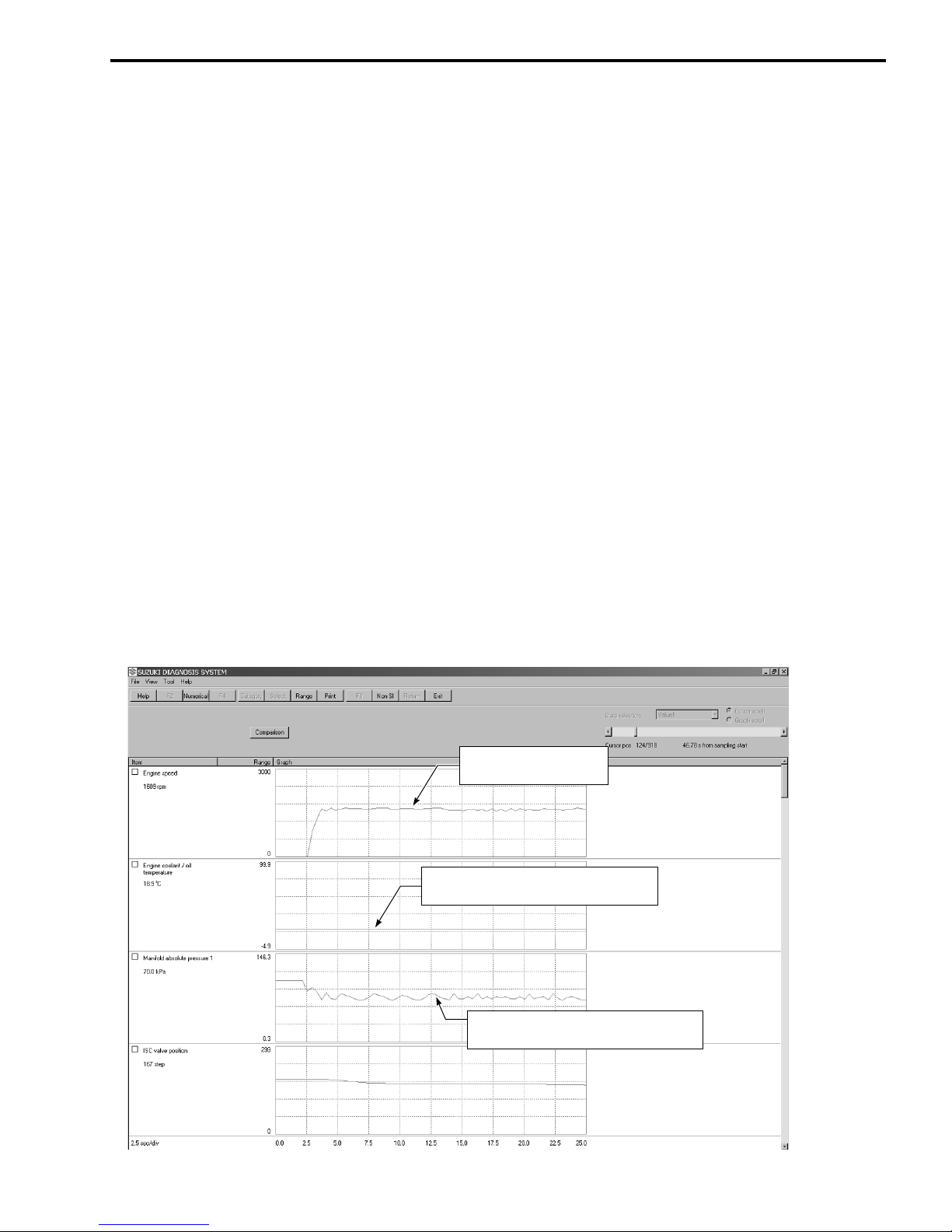
SAMPLE:
Data sampled from cold starting through warm-up
SAMPLE
Check the engine r/min.
XXXX r/min
Check the engine coolant temperature.
XX ˚C
Check the manifold absolute pressure.
XX kPa
8 AN650A/K7 (’07-MODEL)
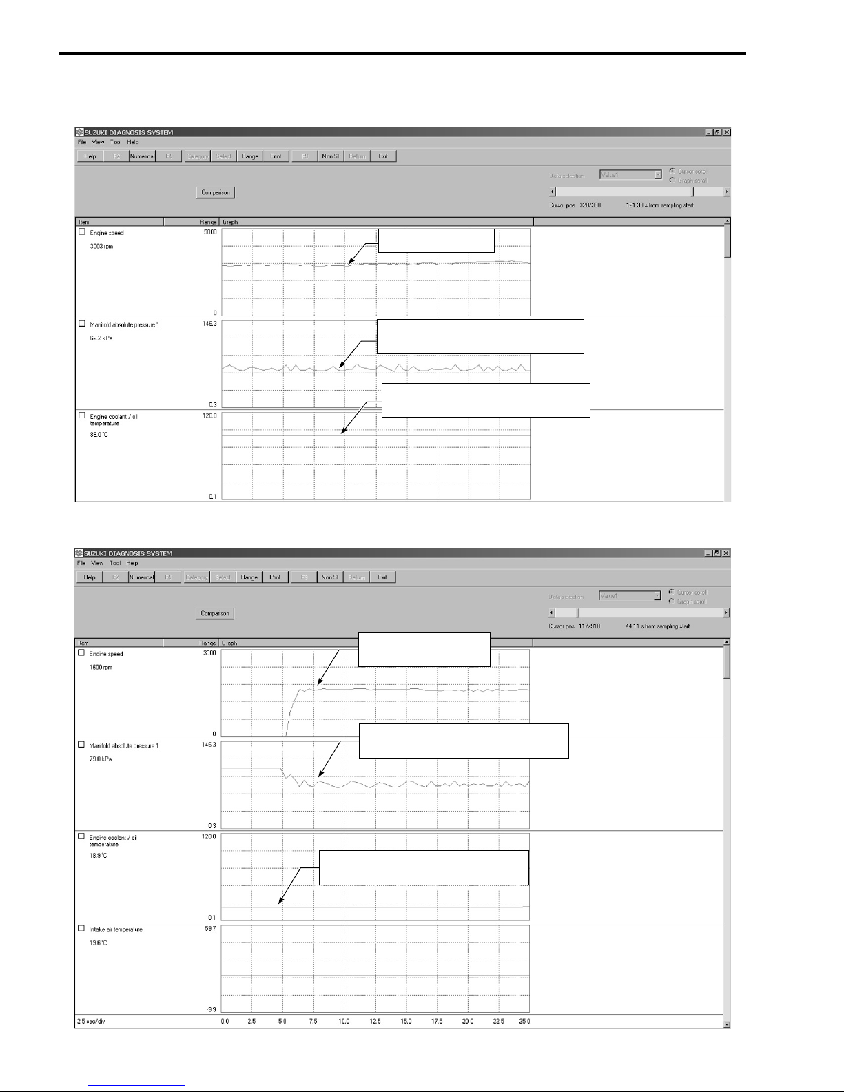
Data at 3 000 r/min under no load
Approx. 3 000 r/min
Check the manifold absolute pressure.
XX kPa
Check the engine coolant temperature.
XX ˚C
Data of manifold absolute pressure operation at the time of cold starting
Check the engine r/min.
SAMPLE
XXXX r/min
Check the manifold absolute pressure.
XX kPa
Check the engine coolant temperature.
XX ˚C

Data of intake negative pressure during idling (100 °C)
Check the manifold absolute pressure.
XX kPa
AN650/AK7 (’07-MODEL) 9
Check the engine coolant temperature.
Approx. 100 ˚C
Data of manifold absolute pressure operation at the time of hot starting
SAMPLE
Check the engine r/min.
XXXX r/min
Check the manifold absolute pressure.
XX kPa
Check the engine coolant temperature.
XX ˚C
10 AN650A/K7 (’07-MODEL)
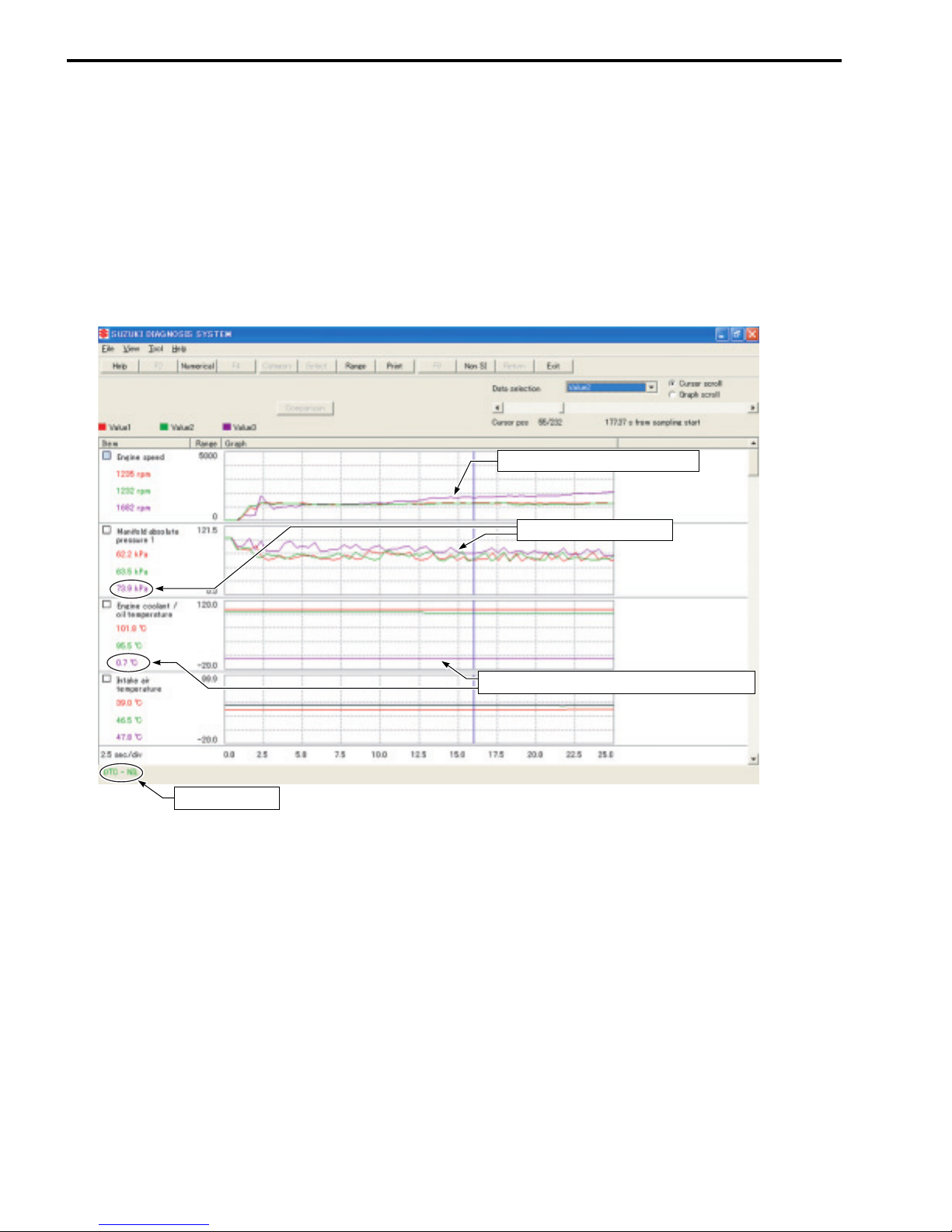
Example of trouble
Three data; value 1 (current data 1), value 2 (past data 2) and value 3 (past data 3); can be made in comparison by showing them in the graph. Read the change of value by comparing the current data to the past data
that have been saved under the same condition, then you may determine how changes have occurred with
the pass of time and identify what problem is currently occurring.
With DTC not output, if the value of engine coolant temperature is found to be lower than the data saved
previously, the possible cause may probably lie in a sensor circuit open or ground circuit opened or influence
of internal resistance value changes, etc.
Unstable idling speed (Too high)
No DTC output
Abnormal curve of graph
Abnormal value of engine coolant temperature
SAMPLE
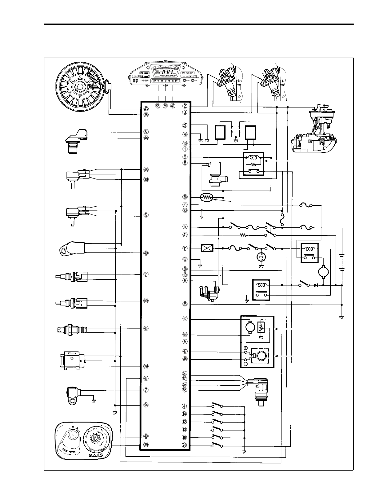
FI SYSTEM WIRING DIAGRAM
AN650/AK7 (’07-MODEL) 11
Fuel injector #1 Fuel injector #2
Crankshaft position sensor(CKPS)
Camshaft position sensor (CMPS)
B/Y
Br
Intake air pressure sensor (IAPS)
Ambient pressure sensor
(APS)
Throttle position sensor
(TPS)
Engine coolant temperature
sensor (ECTS)
Intake air temperature
sensor (IATS)
HO2 sensor (HO2S)
Tip-over sensor (TOS)
Speed sensor
Combination
meter
W
W/G
R
Lg/B
G/Y
P/B
B/Bl
Dg
SAMPLE
P/W O/BlBr/W
*1
ECM/PCM
Gr/W
Gr/B
Ignition coil #1
B/W
B/W
W/Bl
B/Y
Y/Bl
G/Bl
Y/W
R/B
R/Bl
To
Combination
meter
O/W
O/Y
*2
Gr/Y
Cooling
B
fan relay
Y/G
G
Dbr
*3
B/W
Ignition coil #2
PA IR
control
solenoid
valve
HO2 sensor heater
Engine
stop switch
EVAP system
purge control
solenoid
valve
15 A
10 A
Brake light
Ignition
switch
Starter
switch
switch
Brake
light
Side-stand relay
CVT unit
R/W
B/G
Br/R
Y/R
G/R
G/B
B/Lg
P/W
P
W/B
Br
Bl
G
CVT motor
M
Fuel pump
Fuel pump relay
40 A
30 A
Starter
relay
M
Side-stand switch
Pulley position sensor
Secondary pulley
revolution sensor
Immobilizer
B/Br
B/O
Y/Bl
Y
G/W
R/W
Lg/Y
*1
*1
Lg
W/B
Shift up
switch
Shift down
switch
Powe r
switch
Mode
switch
Center stand
switch
Brake light
switch
ISC valve
*1: For E-02, 19, 24
*2: For E-03, 28, 33
*3: For E-33 only
12 AN650A/K7 (’07-MODEL)
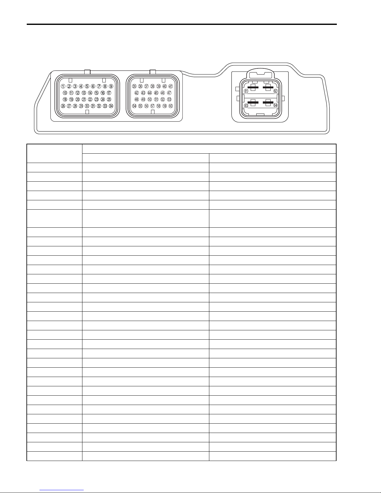
ECM/PCM TERMINAL
ECM TERMINAL
NO.
1 Ignition coil (IG2) ←
2 Fuel injector (#1) ←
3 Fuel injector (#2) ←
4 Shift up switch (UP) ←
5 Pulley position sensor (PPS) ←
6
7 Speed sensor (SPD) ←
8 PAIR control solenoid valve (PAIR) ←
9 Fuel pump relay (FP) ←
0 Ignition coil (IG1) ←
A Cooling fan relay (FRL) ←
B Power switch (POWER) ←
C Mode switch (MODE) ←
D Shift down switch (DOWN) ←
E ——
F ——
G Battery (+B) ←
H Center stand switch (CSTD) ←
I Side-stand switch (SS) ←
J Brake switch (BRK) ←
K ——
L ——
M ——
N ——
O ——
P Ground (E03) ←
Q Ground (E01) ←
R Starter relay (STA) ←
S — TO sensor (DON)
T — IAP sensor (PM)
U ——
CIRCUIT
K6 K7
PTVC heater (PTC) EVAP system purge control solenoid valve
(E-33 only)
SAMPLE
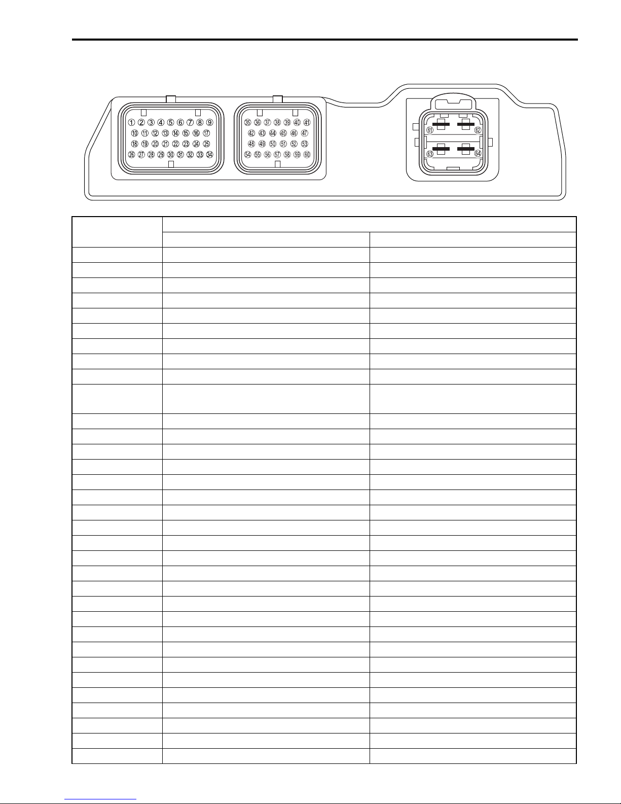
AN650/AK7 (’07-MODEL) 13
ECM TERMINAL
NO.
V ——
W Battery (BATT) ←
X ——
Y Ground (E1) ←
Z CKP sensor (N-) ←
[ CMP sensor (G+) ←
\ HO2 sensor heater (OXH) ←
] Immobilizer (TXCK) (For E-02, 19, 24) ←
^ Immobilizer (RXCK) (For E-02, 19, 24) ←
a
b Injector power voltage (VM) ←
c CKP sensor (N+) ←
d CMP sensor (G-) ←
e HO2 sensor (OX) ←
f
g
h Sensor power (Vcc) ←
i TP sensor (VTA) ←
j IAT sensor (THA) ←
k ECT sensor (THW) ←
l AP sensor (PA) ←
m — ISC valve 1A (IS1A)
n Ground (E2) ←
o Tachometer (TACO) ←
p Meter communication (ETCH) ←
q ——
r IAP sensor (PM) ISC valve 2B (IS2B)
s TO sensor (DON) ISC valve 2A (IS2A)
t IG switch (AT) ISC valve 1B (IS1B)
u Battery (VB) ←
v CVT motor (MO+) ←
w Ground ←
x CVT motor (MO-) ←
CIRCUIT
K6 K7
Immobilizer LED (Meter) (For E-02, 19, 24)
Anti-thief switch (AT) (For E-03, 28, 33)
Secondary pulley revolution sensor (SPR-)
Secondary pulley revolution sensor (SPR+)
SAMPLE
←
←
←

14 AN650A/K7 (’07-MODEL)
FAIL-SAFE FUNCTION
FI system is provided with fail-safe function to allow the engine to start and the motorcycle to run in a minimum performance necessary even under malfunction condition.
ITEM FAIL-SAFE MODE
HO2 sensor Feedback compensation is inhibited.
(Air/fuel ratio is fixed to normal.)
PAIR control solenoid valve ECM stops controlling PAIR control
solenoid valve.
HO2 sensor feedback compensation
is inhibited.
Power for HO2 sensor is shut off.
ISC valve When motor disconnection or lock
occurs, power from ECM is shut off.
The engine can start and can run even if the above signal is not received from each sensor. But, the engine
running condition is not complete, providing only emergency help (by fail-safe circuit). In this case, it is necessary to bring the motorcycle to the workshop for complete repair.
STARTING
ABILITY
“YES” “YES”
“YES” “YES”
“YES” “YES”
RUNNING
ABILITY
SAMPLE

MALFUNCTION CODE AND DEFECTIVE CONDITION
AN650/AK7 (’07-MODEL) 15
DTC No.
C00 NO FAULT
C40 (P0505)
C40 (P0506)
C40 (P0507)
C41 (P2505)
C44
P0130
C44
P0135
C49 PAIR control
P1656
DETECTED
ISC valve
ECM/PCM
power input
signal
HO2 sensor HO2 sensor output voltage is not input
solenoid
valve
ITEM
SAMPLE
DETECTED FAILURE CONDITION CHECK FOR
––––––––––– –––––––––––
Although current is flowing though the
ISC valve motor, the current detection
is not possible.
Idle speed is lower than the desired
idle speed.
Idle speed is higher than the desired
idle speed.
No voltage is applied to the ECM,
although the ignition switch is turned
ON.
to ECM during engine operation and
running condition.
(Sensor voltage < 1.0 V)
In other than the above value, C44
(P0130) is indicated.
The Heater can not operate so that
heater operation voltage is not supply
to the oxygen heater circuit, C44
(P0135) is indicated.
PAIR control solenoid valve voltage is
not input to ECM.
ISC valve circuit open or shorted
to ground
Air passage clogged
ISC valve is fixed
ISC valve pre-set position is
incorrect
ISC valve is fixed
ISC valve pre-set position is
incorrect
Lead wire/coupler connection of
ECM terminal to fuel fuse, fuel
fuse, battery voltage to ECM
(BATT) shorted to ground or
open
HO2 sensor circuit open
HO2 sensor lead wire/coupler
connection
Battery voltage supply to the
HO2 sensor
PAIR control solenoid valve, lead
wire/coupler
16 AN650A/K7 (’07-MODEL)
1
“C40” (P0505 or P0506 and P0507) ISC VALVE CIRCUIT MALFUNCTION
DETECTED CONDITION POSSIBLE CAUSE
C40
(P0505)
C40
(P0506)
C40
(P0507)
Although current is flowing though the
ISC valve motor, the current detection is
not possible.
Idle speed is lower than the desired idle
speed.
Idle speed is higher than the desired
idle speed.
• ISC valve circuit open or shorted to ground
• Power source circuit open
• Air passage clogged
• ISC valve is fixed
• ISC valve pre-set position is incorrect
• ISC valve is fixed
• ISC valve pre-set position is incorrect
ISC valve
B/Lg
P/W
G
W/B
"
* Be careful not to disconnect the ISC valve coupler at least 5 seconds after ignition switch is
turned OFF.
If the ECM coupler or ISC valve coupler is disconnected within 5 seconds after ignition switch
is turned OFF, there is a possibility of an unusual valve position being written in ECM and
causing an error of ISC valve operation.
* When using the multi-circuit tester, do not strongly touch the terminal of the ECM coupler
with a needle pointed tester probe to prevent the terminal damage or terminal bend.
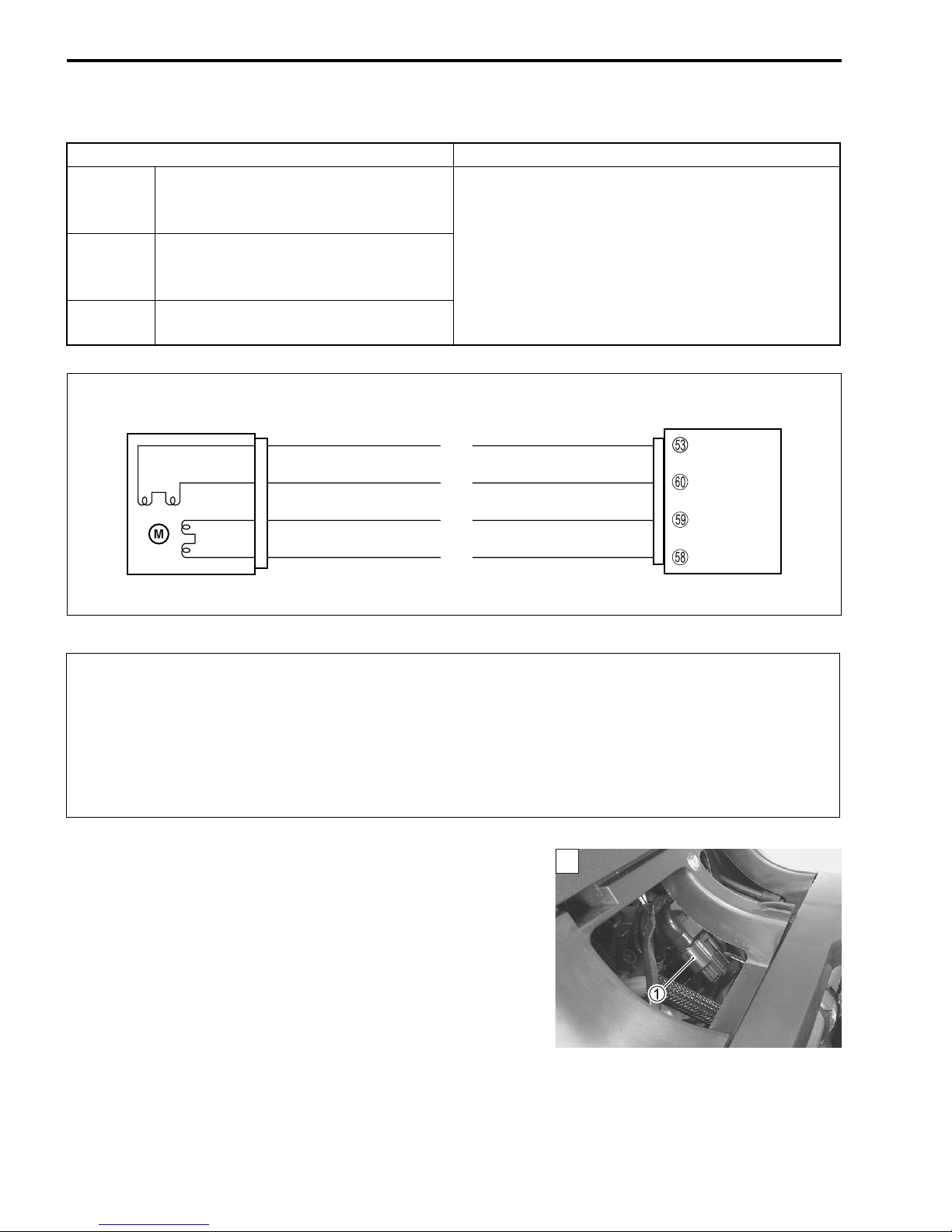
INSPECTION
Step 1
1) Turn the ignition switch OFF.
2) Remove the maintenance lid. (#AN650K3 9-13)
3) Check the ISC valve coupler
If OK, then check the ISC valve lead wire continuity.
SAMPLE
1 for loose or poor contacts.
ECM
ISC. 1A
ISC. 1B
ISC. 2A
ISC. 2B
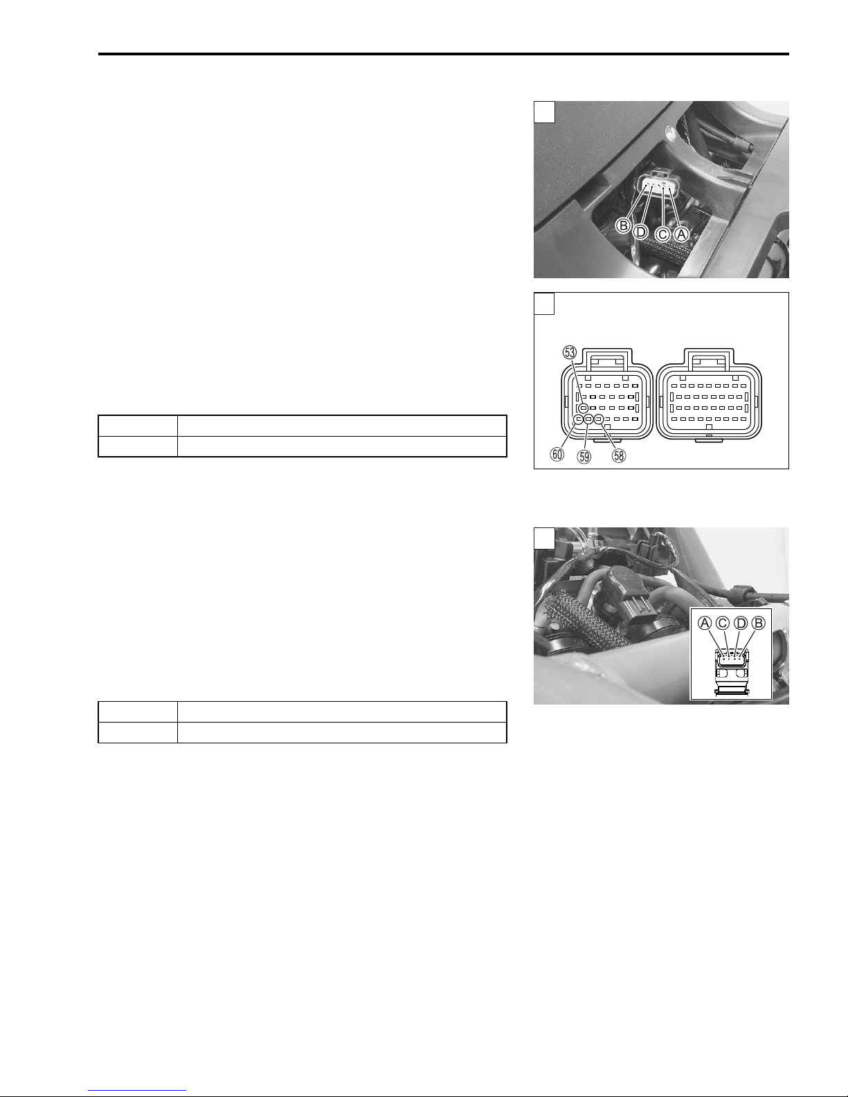
4) Remove the front panel. (#AN650K3 9-8)
1
1
ECM coupler (Harness side)
2
5) Disconnect the ISC valve coupler and ECM couplers.
6) Check the continuity between terminals
minals
(W/B) and
$ ISC valve lead wire continuity: Continuity (%)
! 09900-25008: Multi-circuit tester set
& Tester knob indication: Continuity test (%)
Is the continuity OK?
B (P/W) and
r.
09900-25009: Needle pointed probe set
YES Go to Step 2.
NO Y, B/Lg, P/W, G or W/B wire open.
t, terminals
A (B/Lg) and
C (G) and
s, terminals
AN650/AK7 (’07-MODEL) 17
m, ter-
D
7) After repairing the trouble, clear the DTC using SDS tool.
(Refer to the SDS operation manual for further details.)
Step 2
1) Remove the front box. (#AN650K3 9-18)
2) Measure the resistance between terminals
nals
C and
$ ISC valve resistance: Approx. 80
D.
(Terminal
(Terminal
A – Terminal
C – Terminal
A and
Ω
at 25 °C (77 °F)
B, termi-
B)
D)
SAMPLE
Is the resistance OK?
YES If wire is OK, intermittent trouble or faulty ECM.
NO Replace the ISC valve with a new one.
3) After repairing the trouble, clear the DTC using SDS tool.
(Refer to the SDS operation manual for further details.)
18 AN650A/K7 (’07-MODEL)
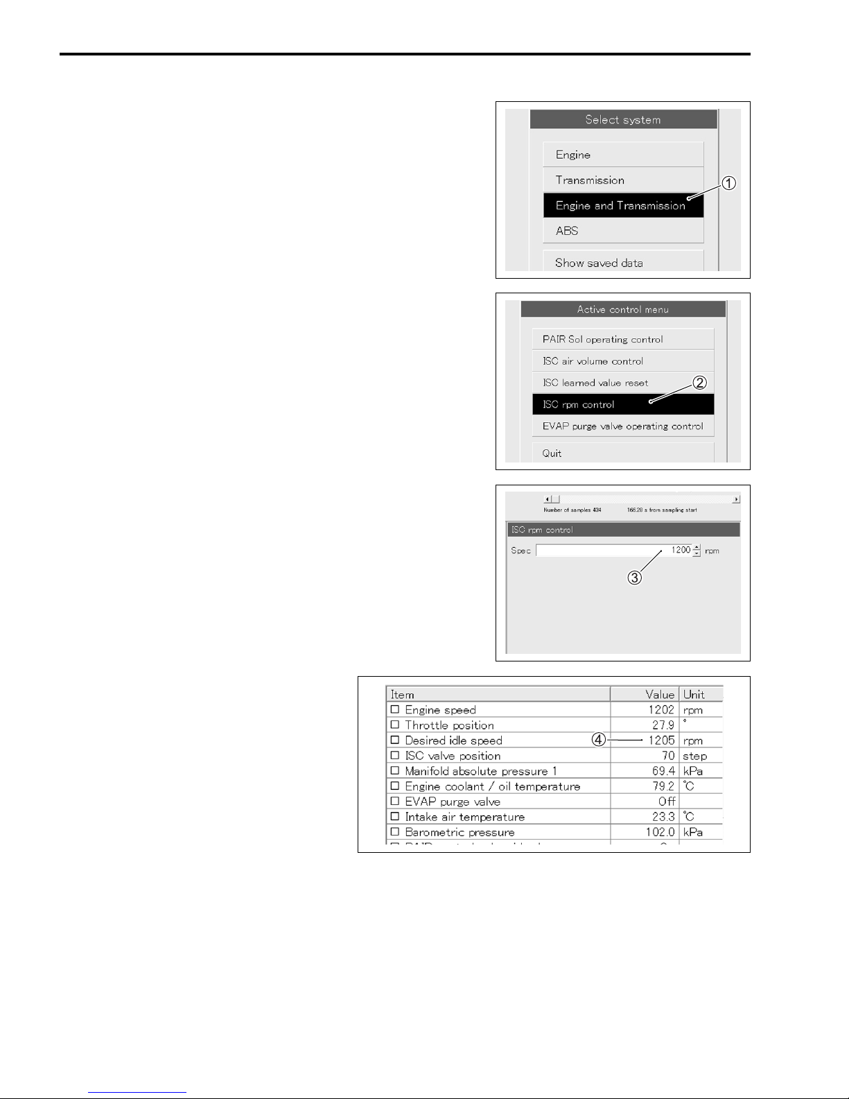
ACTIVE CONTROL INSPECTION (ISC RPM CONTROL)
Check 1
1) Place the motorcycle on the center stand.
2) Pull the parking brake lever and make sure that the rear
wheel is locked.
3) Set up the SDS tool. (Refer to the SDS operation manual for
further details.)
4) Check that the engine is running.
5) Click the “Engine and Transmission”
1.
6) Click the “ISC rpm control”
7) Check that the “Spec”
8) Check that the “Desired idle speed”
idle rpm.
2.
3 is idle speed 1 200 ± 100 rpm.
SAMPLE
4 is within the specified
 Loading...