

Suzuki AN400, AN400ZA, AN400A, 2009 AN400, 2009 AN400ZA Supplementary Service Manual
...
AN400/A/ZA
SUPPLEMENTARY SERVICE MANUAL
USE THIS MANUAL WITH:
AN400 SERVICE MANUAL (99500-34101-01E)
9 9 5 0 1 - 3 4 1 7 0 - 0 1 E
FOREWORD
This SUPPLEMENTARY SERVICE MANUAL is a supplement to SUZUKI AN400 SERVICE MANUAL.
It has been prepared exclusively for the following applicable model.
Applicable model:
AN400/A/ZAK9
This supplementary service manual describes only service information which differ from that of the main manual. Therefore, whenever servicing the above applicable model, consult this supplement first. And for any section, item or description not found in this supplement, refer to the main manual below.
Main Manual:
Manual Name Manual No.
AN400 SERVICE MANUAL 99500-34101-01E
Other information considered as generally known is not included.
Read the GENERAL INFORMATION section to familiarize yourself with the motorcycle and its maintenance.
Use this section as well as other sections to use as a guide for proper inspection and service.
This manual will help you know the motorcycle better so that you can assure your customers of fast and reliable
service.
* This manual has been prepared on the basis of the latest specifications at the time of publication. If modifi-
cations have been made since then, differences may exist between the content of this manual and the
actual motorcycle.
* Illustrations in this manual are used to show the basic principles of operation and work procedures. They
may not represent the actual motorcycle exactly in detail.
* This manual is written for persons who have enough knowledge, skills and tools, including special tools, for
servicing SUZUKI motorcycles. If you do not have the proper knowledge and tools, ask your authorized
SUZUKI motorcycle dealer to help you.
!
WARNING
Inexperienced mechanics or mechanics without the proper tools and equipment may not be able to
properly perform the services described in this manual.
Improper repair may result in injury to the mechanic and may render the motorcycle unsafe for the
rider and passenger.
© COPYRIGHT SUZUKI MOTOR CORPORATION 2009

TABLE OF CONTENTS
NOTE
For the screen toned sections with asterisk (*) in the “TABLE OF CONTENTS” below, refer to the same
sections of the service manual mentioned in the “FOREWORD” of this manual.
Precautions............................................................... 00-i
Precautions ............................................................ 00-1
General Information ................................................... 0-i
General Information ............................................... 0A-1
Maintenance and Lubrication ..................................0B-*
Service Data...........................................................0C-1
Engine ......................................................................... 1-i
Precautions ............................................................... 1-*
Engine General Information and Diagnosis ............1A-*
Emission Control Devices .......................................1B-*
Engine Electrical Devices....................................... 1C-*
Engine Mechanical.................................................1D-1
Engine Lubrication System .....................................1E-*
Engine Cooling System...........................................1F-*
Fuel System ...........................................................1G-1
Ignition System....................................................... 1H-*
Starting System........................................................ 1I-*
Charging System..................................................... 1J-*
Exhaust System ......................................................1K-*
Suspension................................................................. 2-i
Precautions ............................................................... 2-*
Suspension General Diagnosis...............................2A-*
Front Suspension ....................................................2B-*
Rear Suspension....................................................2C-1
Wheels and Tires ...................................................2D-1
00
0
1
2
3
4
5
6
Driveline / Axle ........................................................... 3-*
Precautions ............................................................... 3-*
Drive Chain / Drive Train / Drive Shaft ....................3A-*
Brake ........................................................................... 4-i
Precautions ............................................................... 4-*
Brake Control System and Diagnosis ....................4A-1
Front Brakes............................................................4B-*
Rear Brakes ........................................................... 4C-*
Parking Brake......................................................... 4D-*
ABS ........................................................................ 4E-1
Transmission / Transaxle .......................................... 5-i
Precautions ............................................................... 5-*
Automatic Transmission......................................... 5A-1
Steering....................................................................... 6-i
Precautions ............................................................... 6-*
Steering General Diagnosis ....................................6A-*
Steering / Handlebar ..............................................6B-1
Body and Accessories............................................... 9-i
Precautions ............................................................... 9-*
Wiring Systems ...................................................... 9A-1
Lighting Systems.....................................................9B-*
Combination Meter / Fuel Meter / Horn..................9C-1
Exterior Parts ......................................................... 9D-1
Body Structure ....................................................... 9E-1
9


Table of Contents 00- i
Section 00
Precautions
CONTENTS
NOTE
For the items with asterisk (*) in the “CONTENTS” below, refer to the same section of the service manual
mentioned in the “FOREWORD” of this manual.
00
Precautions ...............................................00-1
Precautions........................................................... 00-1
Warning / Caution / Note...................................... 00-*
General Precautions ............................................ 00-*
Precautions for Electrical Circuit Service ............. 00-*
Precautions for ABS (AN400A/ZAK9) ................. 00-1
00-1 Precautions:
Precautions
Precautions
Precautions
Precautions for ABS (AN400A/ZAK9)
B905H10000004
ABS Wiring
• The ABS parts are connected to various lead wires.
The coupler and lead wire connections, as well as the
lead wire and wire harness routings must be done
correctly. Make sure that the proper clamps are used
and positioned correctly.
NOTE
If all of the connections are not properly
connected, the ABS may not operate
correctly. For connector and coupler
precautions. Refer to “Precautions for
Electrical Circuit Service” in related manual.
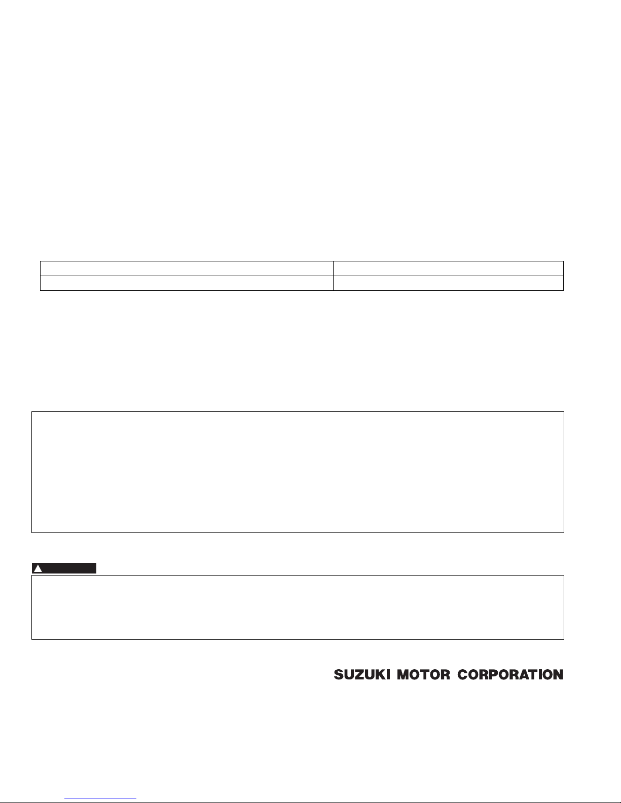
ABS Control Unit/HU
• Never allow dust or water to contact the ABS control
unit/HU.
• Never subject the ABS control unit/HU to strong
impacts or allow them to be dropped.
I649G1000003-02
• The ABS control unit/HU cannot be disassembled.
Replace the whole unit with a new one.
I649G1000004-02
I649G1000005-02

Table of Contents 0- i
Section 0
General Information
CONTENTS
NOTE
For the items with asterisk (*) in the “CONTENTS” below, refer to the same section of the service manual
mentioned in the “FOREWORD” of this manual.
0
General Information ................................ 0A-1
General Description ............................................. 0A-1
Symbols ...............................................................0A-*
Abbreviations .......................................................0A-*
Vehicle Side View (AN400K7) .............................0A-*
Vehicle Side View (AN400ZK7) ...........................0A-*
Vehicle Identification Number ..............................0A-*
Fuel / Oil / Engine Coolant Recommendation......0A-*
Engine Coolant Recommendation .......................0A-*
BREAK-IN Procedures.........................................0A-*
Country and Area Codes .....................................0A-*
Wire Color Symbols .............................................0A-*
Warning, Caution and Information Labels
Location .............................................................0A-*
Abbreviations (AN400A/ZAK9) ........................... 0A-1
Vehicle Side View (AN400/A/ZAK9).................... 0A-1
Country and Area Codes (AN400/A/ZAK9)......... 0A-2
Component Location ........................................... 0A-*
Electrical Components Location ..........................0A-*
Specifications.......................................................0A-3
Specifications (AN400K7) ....................................0A-*
Specifications (AN400ZK7) ..................................0A-*
Specifications (AN400K8) ....................................0A-*
Specifications (AN400ZK8) ..................................0A-*
Specifications (AN400K9) ................................... 0A-3
Specifications (AN400AK9)................................. 0A-3
Specifications (AN400ZAK9) .............................. 0A-4
Special Tools and Equipment ............................. 0A-5
Special Tool ........................................................ 0A-5
Maintenance and Lubrication..................0B-*
Precautions........................................................... 0B-*
Precautions for Maintenance ...............................0B-*
General Description ............................................. 0B-*
Recommended Fluids and Lubricants..................0B-*
Scheduled Maintenance ...................................... 0B-*
Periodic Maintenance Schedule Chart.................0B-*
Lubrication Points ................................................0B-*
Repair Instructions .............................................. 0B-*
Air Cleaner Element Removal and Installation .....0B-*
Air Cleaner Element Inspection ...........................0B-*
Spark Plug Removal and Installation ...................0B-*
Spark Plug Inspection and Cleaning ....................0B-*
Valve Clearance Inspection and Adjustment .......0B-*
Fuel Line Inspection ............................................ 0B-*
Evaporative Emission Control System (E-33
Only).................................................................. 0B-*
Engine Oil and Filter Change .............................. 0B-*
Final Reduction Gear Oil Replacement............... 0B-*
Cooling Fan Filter Removal and Installation ....... 0B-*
Cooling Fan Filter Inspection and Cleaning ........ 0B-*
Drive V-belt Removal and Installation ................. 0B-*
Drive V-belt Inspection ........................................ 0B-*
Throttle Cable Play Inspection and
Adjustment ........................................................ 0B-*
Cooling System Inspection.................................. 0B-*
Air Bleeding From the Cooling Circuit ................. 0B-*
Radiator Hose Inspection.................................... 0B-*
Brake System Inspection .................................... 0B-*
Brake Hose Replacement ................................... 0B-*
Air Bleeding from Brake Fluid Circuit .................. 0B-*
Brake Fluid Replacement.................................... 0B-*
Tire Inspection..................................................... 0B-*
Steering System Inspection ................................ 0B-*
Front Fork Inspection .......................................... 0B-*
Rear Suspension Inspection ............................... 0B-*
Exhaust Pipe and Muffler Mounting
Inspection.......................................................... 0B-*
Chassis Bolt and Nut Inspection ......................... 0B-*
Compression Pressure Check ............................ 0B-*
Oil Pressure Check ............................................. 0B-*
SDS Check.......................................................... 0B-*
Automatic Clutch Inspection................................ 0B-*
Parking Brake (Brake-lock) Inspection................ 0B-*
Parking Brake (Brake-lock) Adjustment .............. 0B-*
Specifications....................................................... 0B-*
Tightening Torque Specifications........................ 0B-*
Special Tools and Equipment ............................. 0B-*
Recommended Service Material ......................... 0B-*
Special Tool ........................................................ 0B-*
Service Data ............................................. 0C-1
Specifications.......................................................0C-1
Service Data (AN400/ZK7).................................. 0C-*
Service Data (AN400/ZK8).................................. 0C-*
Tightening Torque List ........................................ 0C-*
Service Data (AN400K9).....................................0C-1
Service Data (AN400A/ZAK9).............................0C-2
Tightening Torque List (AN400AK9) ...................0C-3
0A-1 General Information:
General Information
General Information
General Description
Abbreviations (AN400A/ZAK9)
NOTE
Please refer to the AN400K8 service manual for other abbreviations which are not given in this manual.
A:
ABS: Anti-lock Brake System
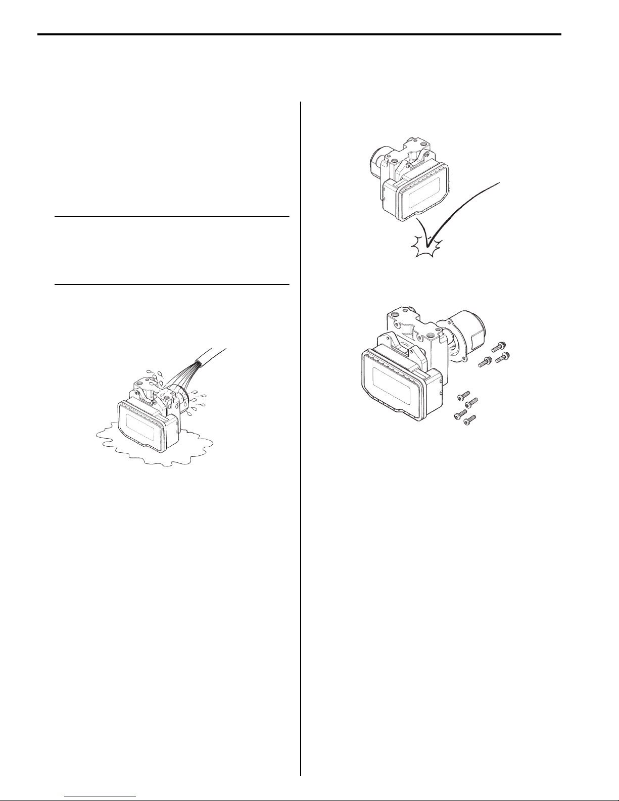
Vehicle Side View (AN400/A/ZAK9)
B905H10101013
NOTE
Difference between illustration and actual
motorcycles may exist depending on the
markets.
SUZUKI AN400 (2009-model)
Right Side
SUZUKI AN400A (2009-model)
Right Side
B905H10101012
I905H1010003-01
Left Side
Left Side
I905H1010001-01
I905H1010004-02
I905H1010002-02
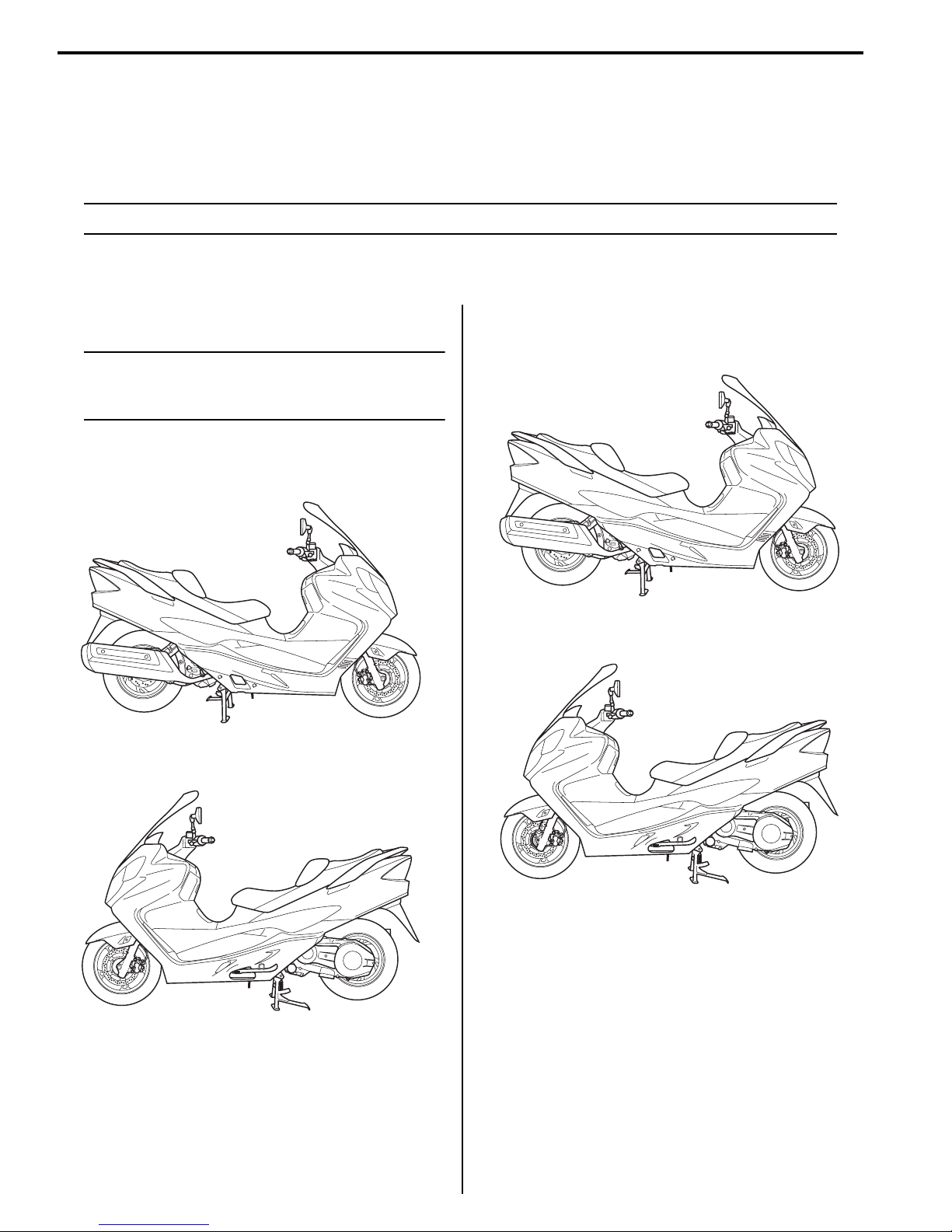
General Information: 0A-2
SUZUKI AN400ZA (2009-model)
Left Side
Right Side
I905H1010005-01
Country and Area Codes (AN400/A/ZAK9)
The following codes stand for the applicable country(-ies) and area(-s).
Model Code Country or Area Effective Frame No.
E-02 U.K. JS1CG111200100924 –
E-03 U.S.A. (Except for California) JS1CK44A 92100001 –
E-19 E.U. JS1CG111100135961 –
AN400 K9
AN400A K9
AN400ZA K9
E-24 Australia JS1CG111300100360 –
E-28 Canada JS1CK44A 92100001 –
E-33 California JS1CK44A 92100001 –
E-51 Korea JS1CG111590100001 –
E-54 Israel JS1CG111490100001 –
E-02 U.K. JS1CG113200100001 –
E-03 U.S.A. (Except for California) JS1CK44B 92100001 –
E-19 E.U. JS1CG113100100001 –
E-24 Australia JS1CG113300100001 –
E-28 Canada JS1CK44B 92100001 –
E-33 California JS1CK44B 92100001 –
E-54 Israel JS1CG113490100001 –
E-02 U.K. JS1CG114200100001 –
E-19 E.U. JS1CG114100100001 –
I905H1010006-02
B905H10101014
0A-3 General Information:
Specifications
Specifications (AN400K9)
NOTE
• These specifications are subject to change without notice.
• Any differences between the AN400K8 (’08-model) and AN400K9 (’09-model) in specifications are
indicated an asterisk mark (*).
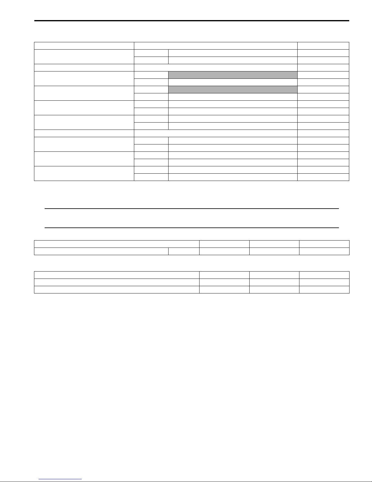
Dimensions and Curb Mass
Item Specification Remark
Overall length 2 270 mm (89.4 in)
Overall width 760 mm (29.9 in)
Overall height 1 385 mm (54.5 in)
Wheelbase 1 585 mm (62.4 in)
Ground clearance 125 mm (4.9 in)
Seat height 710 mm (28.0 in)
* Curb mass 216 kg (476 lbs)
Specifications (AN400AK9)
NOTE
• These specifications are subject to change without notice.
• Any differences between the AN400K9 (’09-model) and AN400AK9 (’09-model) in specifications are
indicated with an asterisk mark (*).
Dimensions and Curb Mass
Item Specification Remark
Overall length 2 270 mm (89.4 in)
Overall width 760 mm (29.9 in)
Overall height 1 385 mm (54.5 in)
Wheelbase 1 585 mm (62.4 in)
Ground clearance 125 mm (4.9 in)
Seat height 710 mm (28.0 in)
Curb mass
* 223 kg (491 lbs) E-33
* 222 kg (489 lbs) Others
B905H10107005
B905H10107006

General Information: 0A-4
Electrical
Item Specification Remark
lgnition type Electronic ignition (Transistorized)
lgnition timing 7° B. T. D. C at 1 450 r/min
Spark plug NGK: CR7E or DENSO: U22ESR-N
Battery 12 V 32.4 kC (9 Ah)/10 HR
Generator Three-phase A.C. generator
Main fuse 30 A
Fuse
10/10/15/10/15/10 A E-02, 19, 24, 54
15/15/15/10/15/10 A E-03, 28, 33
* ABS fuse 15/20 A
Headlight
12 V 60/55 W (H4) + 55 W (H7) E-02, 19, 24, 54
12 V 60/55 W (H4) x 2 E-03, 28, 33
Position/Parking light 12 V 5 W x 2 E-02, 19, 24, 54
Position light 12 V 5 W x 2 E-03, 28, 33
Brake light/Taillight 12 V 21/5 W x 2
License plate light 12 V 5 W
Helmet box light 12 V 5 W
Front turn signal light
12 V 27/8 W E-03, 28, 33
12 V 21 W Others
Rear turn signal light 12 V 21 W
Speedometer/Tachometer light LED
Coolant temperature meter light LED
Fuel level meter light LED
Turn signal indicator light LED x 2
High beam indicator light LED
Brake-lock indicator light LED
Oil change indicator LCD
Fuel injection warning light LED
Immobilizer indicator light LED E-02, 19, 24, 54
* ABS indicator light LED
Specifications (AN400ZAK9)
NOTE
• These specifications are subject to change without notice.
• Any differences between the AN400AK9 (’09-model) and AN400ZAK9 (’09-model) in specifications
are indicated with an asterisk mark (*).
Dimensions and Curb Mass
Item Specification Remark
Overall length 2 270 mm (89.4 in)
Overall width * 825 mm (32.5 in)
Overall height 1 385 mm (54.5 in)
Wheelbase 1 585 mm (62.4 in)
Ground clearance 125 mm (4.9 in)
Seat height 710 mm (28.0 in)
Curb mass * 225 kg (496 lbs)
B905H10107007
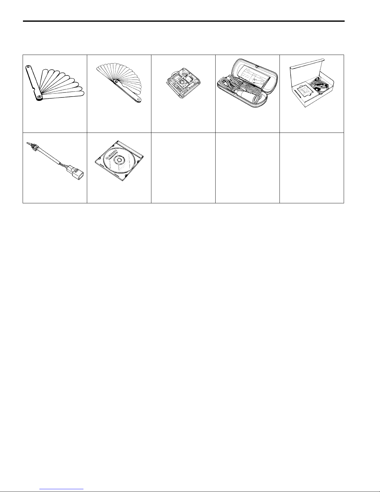
0A-5 General Information:
Special Tools and Equipment
Special Tool
09900–20803
Thickness gauge
09930–82710
Mode select switch
09900–20806
Thickness gauge
99565–01010–020
CD-ROM Ver.20
09900–25008
Multi circuit tester set
09900–25009
Needle-point probe
set
B905H10108002
09904–41010
SUZUKI Diagnostic
system set
General Information
Service Data
Service Data: 0C-1
Specifications
Service Data (AN400K9)
B905H10307004
NOTE
Any differences between the AN400K8 (’08-model) and AN400K9 (’09-model) is service data are
indicated an asterisk mark (*).
Clutch
Unit: mm (in)
Item Specification Limit
Clutch wheel I.D. 160 – 160.2 (6.30 – 6.31) 160.5 (6.32)
Clutch shoe thickness 5.0 (2.0) 2.0 (0.08)
Engage r/min
Lock-up r/min 4 000 – 5 000 r/min —
Transmission
Unit: mm (in) Except ratio
Item Specification Note
Primary reduction ratio 1.000 —
Reduction ratio 2.200 – 0.839
Secondary reduction ratio 2.214 —
Final reduction ratio 2.666 —
Drive V-belt width 25.1 (0.99) 24.1 (0.95)
Movable driven face spring free
length
Movable drive face roller O.D. 26.00 – 26.16 (1.024 – 1.030) —
Drive/driven face ware — 0.4 (0.02)
* 2 600 – 3 200 r/min —
* 145.0 (5.7) * 137.8 (5.43)
Throttle Body
Specification
* 05H2 * 05H3
I.D. No.
Item
E-02, 03, 19, 24, 28, 51, 54 E-33
Bore size 38 mm (1.5 in) ←
Fast idle r/min 1 500 – 2 000 r/min ←
Idle r/min 1 450 ± 100 r/min ←
Throttle cable play 2.0 – 4.0 mm (0.08 – 0.16 in) ←
0C-2 Service Data:
Service Data (AN400A/ZAK9)
NOTE
Any differences between the AN400K9 (’09-model) and AN400A/ZAK9 (’09-model) in service data are
indicated an asterisk mark (*).
Electrical
Unit: mm (in)
Item Standard / Specification Note
HI
Headlight
LO
Meter
Fuse size
Ignition
Signal 15 A
Power source 10 A
Main 30 A
* ABS motor 20 A
* ABS valve 15 A
Wattage
Unit: W
Item
E-02, 19, 24, 54 E-03, 28, 33
Standard / Specification
Speedometer/tachometer light LED ←
Engine coolant temp. gauge light LED ←
Fuel level gauge light LED ←
Immobilizer indicator light LED ←
Oil change indicator LCD ←
FI indicator light LED ←
Brake-lock indicator light LED ←
High beam indicator light LED ←
Turn signal indicator light LED x 2 ←
* ABS indicator light LED ←
10 A E-02, 19, 24, 54
15 A E-03, 28, 33
10 A E-02, 19, 24, 54
15 A E-03, 28, 33
* 10 A
* 15 A
B905H10307005
Service Data: 0C-3
Brake + Wheel
Unit: mm (in)
Item Standard Limit
Brake disc thickness
Front 4.5 ± 0.2 (0.18 ± 0.008) 4.0 (0.16)
Rear 5.0 ± 0.2 (0.20 ± 0.008) 4.5 (0.18)
Brake disc runout — 0.30 (0.01)
Master cylinder bore
Master cylinder piston diameter
Brake caliper cylinder bore
Brake caliper piston diameter
Front
Rear 12.700 – 12.743 (0.500 – 0.502) —
Front
Rear 12.657 – 12.684 (0.498 – 0.499) —
Front 25.400 – 25.450 (1.000 – 1.002) —
Rear 27.00 – 27.05 (1.063 – 1.065) —
Front 25.318 – 25.368 (0.997 – 0.999) —
Rear 26.918 – 26.968 (1.060 – 1.062) —
* 14.000 – 14.043 (0.551 – 0.553) —
* 13.957 – 13.984 (0.549 – 0.551) —
Brake fluid type DOT 4 —
Wheel rim runout
Wheel axle runout
Wheel rim size
Axial — 2.0 (0.08)
Radial — 2.0 (0.08)
Front — 0.25 (0.01)
Rear — 0.25 (0.01)
Front 14 M/C x MT3.00 —
Rear 13 M/C x MT4.00 —
Tightening Torque List (AN400AK9)
B905H10307006
NOTE
Please refer to the AN400K8 service manual for other tightening torque which are not given in this
manual.
Engine
Item N⋅m kgf-m lbf-ft
Main gallery plug M10 18 1.8 13.0
Chassis
Item N⋅m kgf-m lbf-ft
Brake pipe flare nut 16 1.6 11.5
Wheel speed sensor rotor bolt (Front & Rear) 6 0.6 4.5

0C-4 Service Data:

Section 1
Engine
CONTENTS
Table of Contents 1- i
NOTE
For the items with asterisk (*) in the “CONTENTS” below, refer to the same section of the service manual
mentioned in the “FOREWORD” of this manual.
Precautions ................................................. 1-*
Precautions.............................................................. 1-*
Precautions for Engine........................................... 1-*
Engine General Information and
Diagnosis ..................................................1A-*
General Description ............................................. 1A-*
Injection Timing Description .................................1A-*
Self-Diagnosis Function .......................................1A-*
Schematic and Routing Diagram........................ 1A-*
FI System Wiring Diagram ...................................1A-*
Terminal Alignment of ECM Coupler (Harness
Side)...................................................................1A-*
Component Location ........................................... 1A-*
FI System Parts Location.....................................1A-*
Diagnostic Information and Procedures............ 1A-*
Engine Symptom Diagnosis .................................1A-*
DTC Table............................................................1A-*
Fail-Safe Function Table......................................1A-*
FI System Troubleshooting ..................................1A-*
Self-Diagnostic Procedures .................................1A-*
Self-Diagnosis Reset Procedures ........................1A-*
Use of SDS Diagnostic Procedures .....................1A-*
Use of SDS Diagnosis Reset Procedures............1A-*
Show Data When Trouble (Displaying Data at
the Time of DTC) ...............................................1A-*
SDS Check ..........................................................1A-*
Malfunction Code and Defective Condition
Table ..................................................................1A-*
DTC “C12” (P0335): CKP Sensor Circuit
Malfunction.........................................................1A-*
DTC “C13” (P0105-H/L): IAP Sensor Circuit
Malfunction.........................................................1A-*
DTC “C14” (P0120/H/L): TP Sensor Circuit
Malfunction.........................................................1A-*
DTC “C15” (P0115-H/L): ECT Sensor Circuit
Malfunction.........................................................1A-*
DTC “C16” (P0500): Speed Sensor .....................1A-*
DTC “C21” (P0110-H/L): IAT Sensor Circuit
Malfunction.........................................................1A-*
DTC “C23” (P1651-H/L): TO Sensor Circuit
Malfunction.........................................................1A-*
DTC “C24” (P0351): Ignition System
Malfunction.........................................................1A-*
DTC “C28” (P1655): Secondary Throttle
Valve Actuator (STVA) Malfunction................... 1A-*
DTC “C29” (P1654-H/L): Secondary Throttle
Position Sensor (STPS) .................................... 1A-*
DTC “C32” (P0201): Fuel Injector Circuit
Malfunction........................................................ 1A-*
DTC “C40” (P0505, P0506 or P0507): ISC
Valve Circuit Malfunction................................... 1A-*
DTC “C41” (P0230-H/L): FP Relay Circuit
Malfunction........................................................ 1A-*
DTC “42” (P1650): IG Switch Circuit
Malfunction........................................................ 1A-*
DTC “C44” (P0130, P0135): HO2 Sensor
(HO2S) Circuit Malfunction ............................... 1A-*
Specifications....................................................... 1A-*
Service Data........................................................ 1A-*
Special Tools and Equipment ............................. 1A-*
Special Tool ........................................................ 1A-*
Emission Control Devices .......................1B-*
Precautions........................................................... 1B-*
Precautions for Emission Control Devices .......... 1B-*
General Description ............................................. 1B-*
Fuel Injection System Description....................... 1B-*
Crankcase Emission Control System
Description ........................................................ 1B-*
Exhaust Emission Control System
Description ........................................................ 1B-*
Noise Emission Control System Description ....... 1B-*
Repair Instructions .............................................. 1B-*
Heated Oxygen Sensor (HO2S) Removal and
Installation ......................................................... 1B-*
Heated Oxygen Sensor (HO2S) Inspection ........ 1B-*
PCV Hose Inspection .......................................... 1B-*
PCV Hose Removal and Installation ................... 1B-*
Specifications....................................................... 1B-*
Service Data........................................................ 1B-*
Tightening Torque Specifications........................ 1B-*
Special Tools and Equipment ............................. 1B-*
Special Tool ........................................................ 1B-*
Engine Electrical Devices ........................1C-*
Precautions........................................................... 1C-*
Precautions for Engine Electrical Device ............ 1C-*
1

1-ii Table of Contents
Repair Instructions .............................................. 1C-*
ECM Removal and Installation............................ 1C-*
CKP Sensor Inspection ....................................... 1C-*
CKP Sensor Removal and Installation ................ 1C-*
IAP Sensor Inspection......................................... 1C-*
IAP Sensor Removal and Installation.................. 1C-*
TP Sensor Inspection.......................................... 1C-*
TP Sensor Adjustment ........................................ 1C-*
TP Sensor Removal and Installation................... 1C-*
ECT Sensor Inspection ....................................... 1C-*
ECT Sensor Removal and Installation ................ 1C-*
Speed Sensor Inspection .................................... 1C-*
Speed Sensor Removal and Installation ............. 1C-*
IAT Sensor Inspection......................................... 1C-*
IAT Sensor Removal and Installation.................. 1C-*
TO Sensor Inspection ......................................... 1C-*
TO Sensor Removal and Installation .................. 1C-*
STP Sensor Inspection ....................................... 1C-*
STP Sensor Adjustment...................................... 1C-*
STP Sensor Removal and Installation ................ 1C-*
ISC Valve Inspection........................................... 1C-*
ISC Valve Removal and Installation.................... 1C-*
ISC Valve Pre-set (AN400/ZK7).......................... 1C-*
ISC Valve Preset and Opening Initialization
(AN400/ZK8) ..................................................... 1C-*
HO2 Sensor Inspection ....................................... 1C-*
HO2 Sensor Removal and Installation ................ 1C-*
Specifications....................................................... 1C-*
Service Data........................................................ 1C-*
Tightening Torque Specifications........................ 1C-*
Special Tools and Equipment ............................. 1C-*
Special Tool ........................................................ 1C-*
Engine Mechanical .................................. 1D-1
Precautions........................................................... 1D-*
Precautions for Engine Mechanical..................... 1D-*
Schematic and Routing Diagram........................1D-1
Camshaft and Sprocket Assembly Diagram ....... 1D-*
Throttle Cable Routing Diagram.......................... 1D-*
Throttle Cable Routing Diagram (AN400/A/
ZAK9)................................................................1D-1
Diagnostic Information and Procedures............ 1D-*
Compression Pressure Check ............................ 1D-*
Repair Instructions ..............................................1D-2
Engine Components Removable with the
Engine in Place ................................................. 1D-*
Engine Assembly Removal and Installation ........ 1D-*
Crankcase bracket Removal and Installation...... 1D-*
Crankcase bracket Inspection............................. 1D-*
Air Cleaner Box Removal and Installation........... 1D-*
Air Cleaner Element Inspection........................... 1D-*
Air Cleaner Drain Plug Inspection ....................... 1D-*
Throttle Cable Removal and Installation ............. 1D-*
Throttle Cable Adjustment................................... 1D-*
Throttle Body Components ................................. 1D-*
Throttle Body Construction.................................. 1D-*
Throttle Body Removal and Installation .............. 1D-*
Throttle Body Disassembly and Assembly.......... 1D-*
Throttle Body Inspection and Cleaning ............... 1D-*
Engine Top Side Disassembly ............................ 1D-*
Engine Top Side Assembly ................................. 1D-*
Camshaft Inspection ........................................... 1D-*
Cam Chain Tension Adjuster Inspection............. 1D-*
Cam Chain Guide Inspection .............................. 1D-*
Cylinder Head Disassembly and Reassembly .... 1D-*
Cylinder Head and Related Parts Inspection ...... 1D-*
Valve Guide Replacement .................................. 1D-*
Valve Seat Repair ............................................... 1D-*
Cylinder Disassembly and Assembly .................. 1D-*
Cylinder Inspection.............................................. 1D-*
Piston Ring Removal and Installation ................. 1D-*
Piston and Related Parts Inspection ................... 1D-*
Engine Bottom Side Disassembly ....................... 1D-*
Engine Bottom Side Assembly ............................ 1D-*
Cam Chain Tensioner Inspection........................ 1D-*
Conrod and Crankshaft Inspection...................... 1D-*
Width Between Crankshaft Webs ....................... 1D-*
Bearing Inspection .............................................. 1D-*
Bearing Removal and Installation ....................... 1D-*
Rear Suspension Mounting Bushing Removal
and Installation .................................................. 1D-*
Engine Bottom Side Assembly (AN400/A/
ZAK9) ................................................................1D-2
Specifications.......................................................1D-3
Service Data........................................................ 1D-*
Tightening Torque Specifications........................1D-3
Special Tools and Equipment .............................1D-3
Recommended Service Material .........................1D-3
Engine Lubrication System ..................... 1E-*
Precautions........................................................... 1E-*
Precautions for Engine Oil .................................. 1E-*
Schematic and Routing Diagram ........................ 1E-*
Engine Lubrication System Chart Diagram ......... 1E-*
Engine Lubrication Circuit Diagram..................... 1E-*
Diagnostic Information and Procedures............ 1E-*
Engine Lubrication Symptom Diagnosis ............. 1E-*
Oil Pressure Check ............................................. 1E-*
Repair Instructions .............................................. 1E-*
Engine Oil and Filter Replacement ..................... 1E-*
Oil Sump Filter Removal and Installation ............ 1E-*
Oil Sump Filter Cleaning ..................................... 1E-*
Oil Pump Removal and Installation ..................... 1E-*
Oil Pump Inspection ............................................ 1E-*
Piston Cooling Nozzle Removal and
Installation ......................................................... 1E-*
Piston Cooling Nozzle Inspection........................ 1E-*
Specifications....................................................... 1E-*
Service Data........................................................ 1E-*
Tightening Torque Specifications........................ 1E-*
Special Tools and Equipment ............................. 1E-*
Special Tool ........................................................ 1E-*
Engine Cooling System ........................... 1F-*
Precautions............................................................1F-*
Engine Cooling System Warning .........................1F-*
General Description ..............................................1F-*
Cooling System Description .................................1F-*

Table of Contents 1-iii
Engine Coolant Description ................................. 1F-*
Cooling Fan Thermo-Switch Description..............1F-*
Engine Coolant Temperature Sensor
Description .........................................................1F-*
Schematic and Routing Diagram.........................1F-*
Cooling Circuit Diagram ....................................... 1F-*
Radiator Hose Routing Diagram ..........................1F-*
Component Location ............................................1F-*
Engine Cooling System Components
Location .............................................................1F-*
Diagnostic Information and Procedures.............1F-*
Engine Cooling Symptom Diagnosis....................1F-*
Repair Instructions ...............................................1F-*
Cooling Circuit Inspection ....................................1F-*
Radiator Cap Inspection ...................................... 1F-*
Radiator Removal and Installation .......................1F-*
Radiator Cleaning ................................................1F-*
Radiator Hose Inspection.....................................1F-*
Radiator Hose Removal and Installation..............1F-*
Radiator Reservoir Tank Removal and
Installation..........................................................1F-*
Cooling Fan Inspection ........................................1F-*
Cooling Fan Removal and Installation .................1F-*
Cooling Fan Thermo-Switch Removal and
Installation..........................................................1F-*
Cooling Fan Thermo-Switch Inspection ...............1F-*
ECT Sensor Removal and Installation .................1F-*
ECT Sensor Inspection ........................................1F-*
Thermostat Removal and Installation...................1F-*
Thermostat Inspection .........................................1F-*
Water Pump Components....................................1F-*
Water Pump Construction ....................................1F-*
Water Pump Removal and Installation.................1F-*
Water Pump Disassembly and Assembly ............1F-*
Water Pump Related Parts Inspection .................1F-*
Specifications........................................................1F-*
Service Data ........................................................1F-*
Tightening Torque Specifications.........................1F-*
Special Tools and Equipment ..............................1F-*
Recommended Service Material ..........................1F-*
Special Tool .........................................................1F-*
Fuel System .............................................1G-1
Precautions........................................................... 1G-*
Precautions for Fuel System ............................... 1G-*
Schematic and Routing Diagram........................ 1G-*
Fuel Tank Hose Construction ............................. 1G-*
Diagnostic Information and Procedures............ 1G-*
Fuel System Diagnosis ....................................... 1G-*
Repair Instructions ..............................................1G-1
Fuel System Components................................... 1G-*
Fuel Tank Heat Shield Construction ................... 1G-*
Fuel Cut Valve Removal and Installation ............ 1G-*
Fuel Tank Removal and Installation.................... 1G-*
Fuel Pump Assembly Removal and
Installation......................................................... 1G-*
Fuel Drain Tray and FTPC Valve Removal
and Installation.................................................. 1G-*
Fuel Cut Valve Inspection ................................... 1G-*
FTPC Valve Inspection ....................................... 1G-*
Fuel Pump Disassembly and Assembly .............. 1G-*
Fuel Pressure Inspection .................................... 1G-*
Fuel Pump Relay Inspection ............................... 1G-*
Fuel Mesh Filter Inspection ................................. 1G-*
Fuel Level Gauge Inspection .............................. 1G-*
Fuel Pump Inspection ......................................... 1G-*
Fuel Injector Inspection ....................................... 1G-*
Fuel Injector Removal and Installation ................ 1G-*
Fuel Pump Components (AN400/A/ZAK9)......... 1G-1
Fuel Pump Disassembly and Assembly
(AN400/A/ZAK9) .............................................. 1G-2
Specifications...................................................... 1G-2
Service Data........................................................ 1G-*
Tightening Torque Specifications....................... 1G-2
Special Tools and Equipment ............................ 1G-2
Special Tool ........................................................ 1G-*
Recommended Service Material ........................ 1G-2
Ignition System.........................................1H-*
General Description ............................................. 1H-*
Immobilizer Description (For E-02, 19, 24, 54) .... 1H-*
Schematic and Routing Diagram........................ 1H-*
Ignition System Diagram ..................................... 1H-*
Diagnostic Information and Procedures............ 1H-*
Ignition System Symptom Diagnosis................... 1H-*
No Spark or Poor Spark ...................................... 1H-*
Repair Instructions .............................................. 1H-*
Spark Plug Removal and Installation .................. 1H-*
Spark Plug Inspection and Cleaning ................... 1H-*
Ignition Coil Inspection ........................................ 1H-*
Ignition Coil Assembly Removal and
Installation ......................................................... 1H-*
Spark Plug Removal and Installation .................. 1H-*
Spark Plug Inspection ......................................... 1H-*
CKP Sensor Inspection ....................................... 1H-*
CKP Sensor Removal and Installation ................ 1H-*
Engine Stop Switch Inspection............................ 1H-*
Ignition Switch Inspection.................................... 1H-*
Ignition Switch Removal and Installation............. 1H-*
Specifications....................................................... 1H-*
Service Data........................................................ 1H-*
Special Tools and Equipment ............................. 1H-*
Special Tool ........................................................ 1H-*
Starting System ......................................... 1I-*
Schematic and Routing Diagram..........................1I-*
Starting System Diagram ......................................1I-*
Component Location .............................................1I-*
Starting System Components Location................. 1I-*
Diagnostic Information and Procedures.............. 1I-*
Starter Motor will not Run......................................1I-*
Repair Instructions ................................................1I-*
Starter Motor Components.................................... 1I-*
Starter Motor Removal and Installation................. 1I-*
Starter Motor Disassembly and Assembly ............1I-*
Starter Motor Inspection........................................ 1I-*
Starter Relay Removal and Installation................. 1I-*
Starter Relay Inspection........................................1I-*

1-iv Table of Contents
Turn Signal / Side-stand Relay Removal and
Installation........................................................... 1I-*
Side-stand / Ignition Interlock System Parts
Inspection............................................................1I-*
Starter Clutch Component..................................... 1I-*
Starter Clutch Removal and Installation................ 1I-*
Starter Clutch Inspection....................................... 1I-*
Starter Clutch Disassembly and Assembly ........... 1I-*
Starter Button Inspection....................................... 1I-*
Specifications......................................................... 1I-*
Service Data.......................................................... 1I-*
Tightening Torque Specifications.......................... 1I-*
Special Tools and Equipment ...............................1I-*
Recommended Service Material ........................... 1I-*
Special Tool .......................................................... 1I-*
Charging System.......................................1J-*
Schematic and Routing Diagram.........................1J-*
Charging System Diagram ................................... 1J-*
Component Location ............................................1J-*
Charging System Components Location.............. 1J-*
Diagnostic Information and Procedures............. 1J-*
Charging System Symptom Diagnosis................. 1J-*
Battery Runs Down Quickly ................................. 1J-*
Repair Instructions ............................................... 1J-*
Battery Current Leakage Inspection..................... 1J-*
Regulated Voltage Inspection .............................. 1J-*
Generator Coil Resistance Inspection.................. 1J-*
Generator No-load Performance Inspection ........ 1J-*
Regulator/Rectifier Inspection (Except
AN400K8 E-03, 28, 33) ...................................... 1J-*
Regulator/Rectifier Inspection (AN400K8 E-
03, 28, 33 only) .................................................. 1J-*
Generator Removal and Installation..................... 1J-*
Battery Components ............................................ 1J-*
Battery Initial Charging......................................... 1J-*
Battery Visual Inspection...................................... 1J-*
Battery Recharging .............................................. 1J-*
Battery Removal and Installation ......................... 1J-*
Specifications........................................................ 1J-*
Service Data......................................................... 1J-*
Tightening Torque Specifications......................... 1J-*
Special Tools and Equipment ..............................1J-*
Special Tool ......................................................... 1J-*
Exhaust System........................................1K-*
Precautions........................................................... 1K-*
Precautions for Exhaust System ......................... 1K-*
Repair Instructions .............................................. 1K-*
Exhaust System Construction (AN400/ZK7)....... 1K-*
Exhaust System Construction (AN400/ZK8)....... 1K-*
Exhaust Pipe / Muffler Removal and
Installation ......................................................... 1K-*
Exhaust System Inspection................................. 1K-*
HO2 Sensor Inspection ....................................... 1K-*
Specifications....................................................... 1K-*
Tightening Torque Specifications........................ 1K-*
Special Tools and Equipment ............................. 1K-*
Recommended Service Material ......................... 1K-*
Engine
Engine Mechanical
Schematic and Routing Diagram
Engine Mechanical: 1D-1
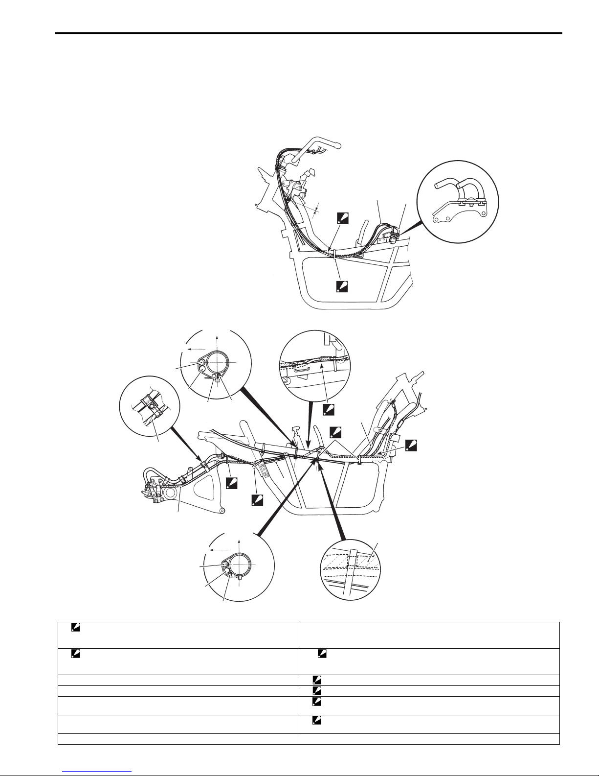
Throttle Cable Routing Diagram (AN400/A/ZAK9)
Upside
Inside
4
“a”
“D”
9
B905H11402003
8
7
5
3
6
“C”
3
1
4
“A”
5
“B”
2
4
Upside
4
Inside
4
5
3
I905H1140001-02
1. Clamp
: Bind the parking brake cable, starter motor lead wire and seatlock cable with the clamp.
2. Clamp
: Bind the parking brake cable and starter motor lead wire with the
clamp.
3. Seat-lock cable “A”: Pass the parking brake cable into the guide.
4. Parking brake cable “B”: Pass the parking brake cable inside of the brake hose.
5. Starter motor lead wire “C”: Pass the parking brake cable under the brake pipe. Do not slacken the
6. Brake pipe “D”: Pass the throttle cable No. 2 over the throttle cable No. 1. Pass the
7. Throttle cable No. 1 “a”: 0 mm (0 in)
8. Throttle cable No. 2
9. Clamp
: Clamp the throttle cable at white taping point.
parking brake cable.
throttle cables inside of the wiring harness.
1D-2 Engine Mechanical:
Repair Instructions
Engine Bottom Side Assembly (AN400/A/ZAK9)
B905H11406036
For engine bottom side assembly other than the
following, refer to “Engine Bottom Side Assembly” in
related manual.
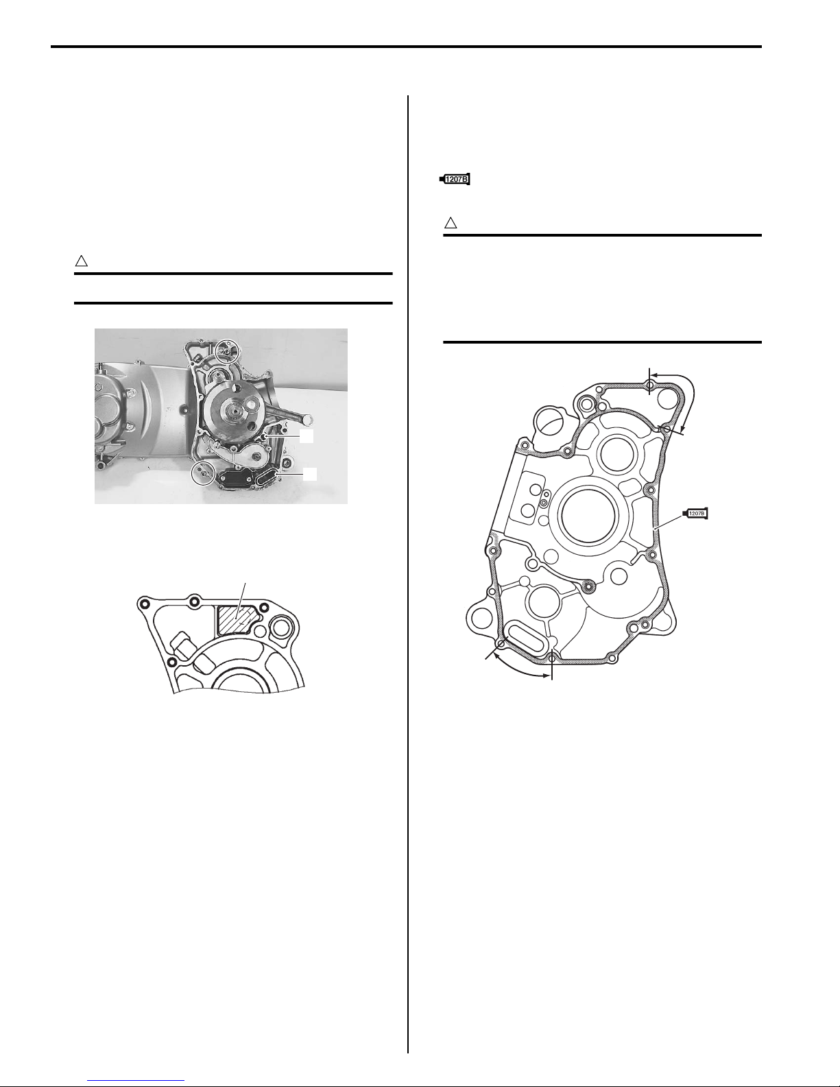
Crankcase
• Install the O-rings (1) and (2).
• Install the dowel pins.
!
CAUTION
Replace the O-rings with the new ones.
1
2
• Clean and degrees the crankcase mating surfaces
(both surfaces) with a cleaning solvent.
• Apply bond to the right crankcase and part “a” of the
left crankcase.
: Sealant 99000–31140 (SUZUKI BOND
No.1207B or equivalent)
!
CAUTION
• Coat the sealant evenly without break.
• Application of sealant must be performed
within a short period of time.
• Take extreme care not to let sealant enter
into the oil passages or bearings.
“a”
I705H1140118-04
• Install the oil breather separator (3) to the left
crankcase.
3
I905H1140003-01
“a”
I905H1140002-01
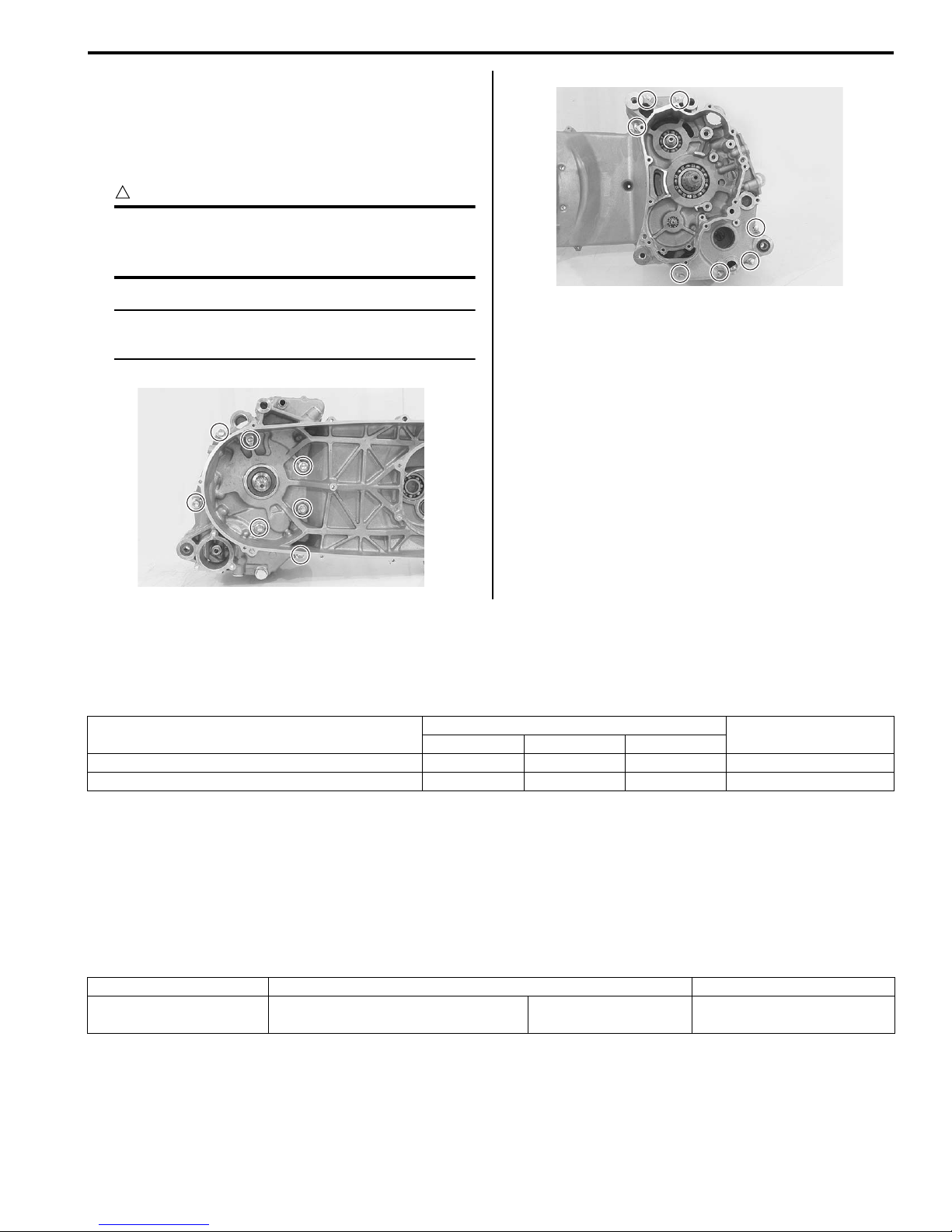
• Tighten the crankcase bolts to the specified torque.
Tightening torque
Crankcase bolt (M6): 11 N·m (1.1 kgf-m, 8.0 lbf-ft)
Crankcase bolt (M8): 22 N·m (2.2 kgf-m, 16.0 lbfft)
!
CAUTION
Tighten the larger diameter crankcase bolts
first and then smaller ones diagonally and
evenly.
NOTE
After crankcase bolts have been tightened,
check it crankshaft rotate smoothly.
Engine Mechanical: 1D-3
I705H1140101-01
I705H1140102-01
Specifications
Tightening Torque Specifications
Fastening part
N⋅m kgf-m lbf-ft
Crankcase bolt (M6) 11 1.1 8.0 )(Page 1D-3)
Crankcase bolt (M8) 22 2.2 16.0 )(Page 1D-3)
Reference:
For the tightening torque of fastener not specified in this section, refer to “Tightening Torque List” in Section 0C in
related manual.
Tightening torque
B905H11407002
Note
Special Tools and Equipment
Recommended Service Material
Material SUZUKI recommended product or Specification Note
Sealant SUZUKI BOND No.1207B or
equivalent
P/No.: 99000–31140 )(Page 1D-2)
B905H11408001
1G-1 Fuel System:
Engine
Fuel System
Repair Instructions
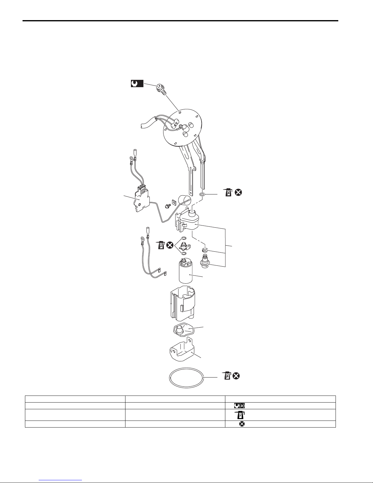
Fuel Pump Components (AN400/A/ZAK9)
(a)
9
1
B905H11706017
2
4
5
6
7
1. Fuel level gauge 5. Fuel pump 9. Fuel pump mounting bolt
2. O-ring 6. Fuel mesh filter : 10 N⋅m (1.0 kgf-m, 7.0 lbf-ft)
3. Fuel pressure regulator assembly 7. Dust cover : Apply engine oil.
3
8
I905H1170003-01
4. O-ring 8. O-ring : Do not reuse.
Fuel System: 1G-2
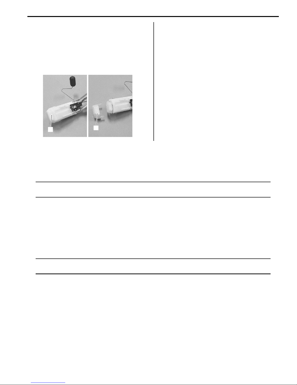
Fuel Pump Disassembly and Assembly (AN400/
A/ZAK9)
B905H11706018
Disassembly
1) Remove the fuel pump assembly.
Refer to “Fuel Pump Assembly Removal and
Installation” in related manual.
2) Remove the dust cover (1).
1
1
I905H1170002-01
Specifications
3) For the other procedure, refer to “Fuel Pump
Disassembly and Assembly” in related manual.
Assembly
Assemble the fuel pump assembly in the reverse order
of the disassembly.
Refer to “Fuel Pump Disassembly and Assembly” in
related manual.
Tightening Torque Specifications
B905H11707002
NOTE
The specified tightening torque is described in the following.
“Fuel Pump Components (AN400/A/ZAK9)” (Page 1G-1)
Reference:
For the tightening torque of fastener not specified in this section, refer to “Tightening Torque List” in Section 0C in
related manual.
Special Tools and Equipment
Recommended Service Material
NOTE
Required service material is also described in the following.
“Fuel Pump Components (AN400/A/ZAK9)” (Page 1G-1)
B905H11708003

1G-3 Fuel System:

Table of Contents 2- i
Section 2
Suspension
CONTENTS
NOTE
For the items with asterisk (*) in the “CONTENTS” below, refer to the same section of the service manual
mentioned in the “FOREWORD” of this manual.
Precautions ................................................. 2-*
Precautions.............................................................. 2-*
Precautions for Suspension ................................... 2-*
Suspension General Diagnosis...............2A-*
Diagnostic Information and Procedures............ 2A-*
Suspension and Wheel Symptom Diagnosis .......2A-*
Front Suspension .....................................2B-*
Repair Instructions .............................................. 2B-*
Front Fork Components .......................................2B-*
Front Fork Removal and Installation ....................2B-*
Front Fork Disassembly and Assembly................2B-*
Front Fork Inspection ...........................................2B-*
Front Fork Parts Inspection..................................2B-*
Specifications....................................................... 2B-*
Service Data ........................................................2B-*
Tightening Torque Specifications.........................2B-*
Special Tools and Equipment ............................. 2B-*
Recommended Service Material ..........................2B-*
Special Tool .........................................................2B-*
Rear Suspension ..................................... 2C-1
Repair Instructions ..............................................2C-1
Rear Suspension Components ........................... 2C-*
Rear Suspension Assembly Construction........... 2C-*
Rear Swingarm Components.............................. 2C-*
Rear Shock Absorber and Rear Shock
Absorber Assembly Removal and
Installation......................................................... 2C-*
Rear Suspension Inspection ............................... 2C-*
Rear Shock Absorber Inspection ........................ 2C-*
Rear Shock Absorber Gas Pressure Release..... 2C-*
Rear Suspension Adjustment ............................. 2C-*
Rear Swingarm Removal and Installation ........... 2C-*
Rear Swingarm Related Parts Inspection ........... 2C-*
Rear Swingarm Dust Seal / Bearing Removal
and Installation.................................................. 2C-*
Cushion Lever and Cushion Rod Inspection....... 2C-*
Cushion Lever Bearing Removal and
Installation......................................................... 2C-*
Crankcase Bracket Construction......................... 2C-*
Crankcase Bracket Removal and Installation ..... 2C-*
Crankcase Bracket Related Parts Inspection...... 2C-*
Crankcase Bracket Bearing Removal and
Installation ......................................................... 2C-*
Rear Swingarm Construction (AN400/A/
ZAK9) ................................................................2C-1
Specifications....................................................... 2C-*
Service Data........................................................ 2C-*
Tightening Torque Specifications........................ 2C-*
Special Tools and Equipment ............................. 2C-*
Recommended Service Material ......................... 2C-*
Special Tool ........................................................ 2C-*
Wheels and Tires ..................................... 2D-1
Precautions........................................................... 2D-*
Precautions for Wheel and Tire........................... 2D-*
Repair Instructions ..............................................2D-1
Front Wheel Components ................................... 2D-*
Front Wheel Assembly Construction................... 2D-*
Front Wheel Assembly Removal and
Installation ......................................................... 2D-*
Front Wheel Related Parts Inspection ................ 2D-*
Front Wheel Dust Seal / Bearing Removal
and Installation .................................................. 2D-*
Rear Wheel Components.................................... 2D-*
Rear Wheel Assembly Removal and
Installation ......................................................... 2D-*
Rear Wheel Related Parts Inspection ................. 2D-*
Tire Removal and Installation.............................. 2D-*
Wheel/Tire/Air Valve Inspection and Cleaning .... 2D-*
Air Valve Removal and Installation ..................... 2D-*
Wheel Balance Check and Adjustment............... 2D-*
Front Wheel Components (AN400A/ZAK9) ........2D-1
Front Wheel Assembly Construction
(AN400A/ZAK9) ................................................2D-2
Front Wheel Assembly Removal and
Installation (AN400A/ZAK9) ..............................2D-3
Rear Wheel Components (AN400A/ZAK9) .........2D-4
Rear Wheel Assembly Construction
(AN400A/ZAK9) ................................................2D-5
Rear Wheel Assembly Removal and
Installation (AN400A/ZAK9) ..............................2D-6
2

2-ii Table of Contents
Specifications.......................................................2D-7
Service Data........................................................ 2D-*
Tightening Torque Specifications........................2D-7
Special Tools and Equipment .............................2D-7
Recommended Service Material .........................2D-7
Special Tool ........................................................2D-7
Suspension
Rear Suspension
Rear Suspension: 2C-1
Repair Instructions
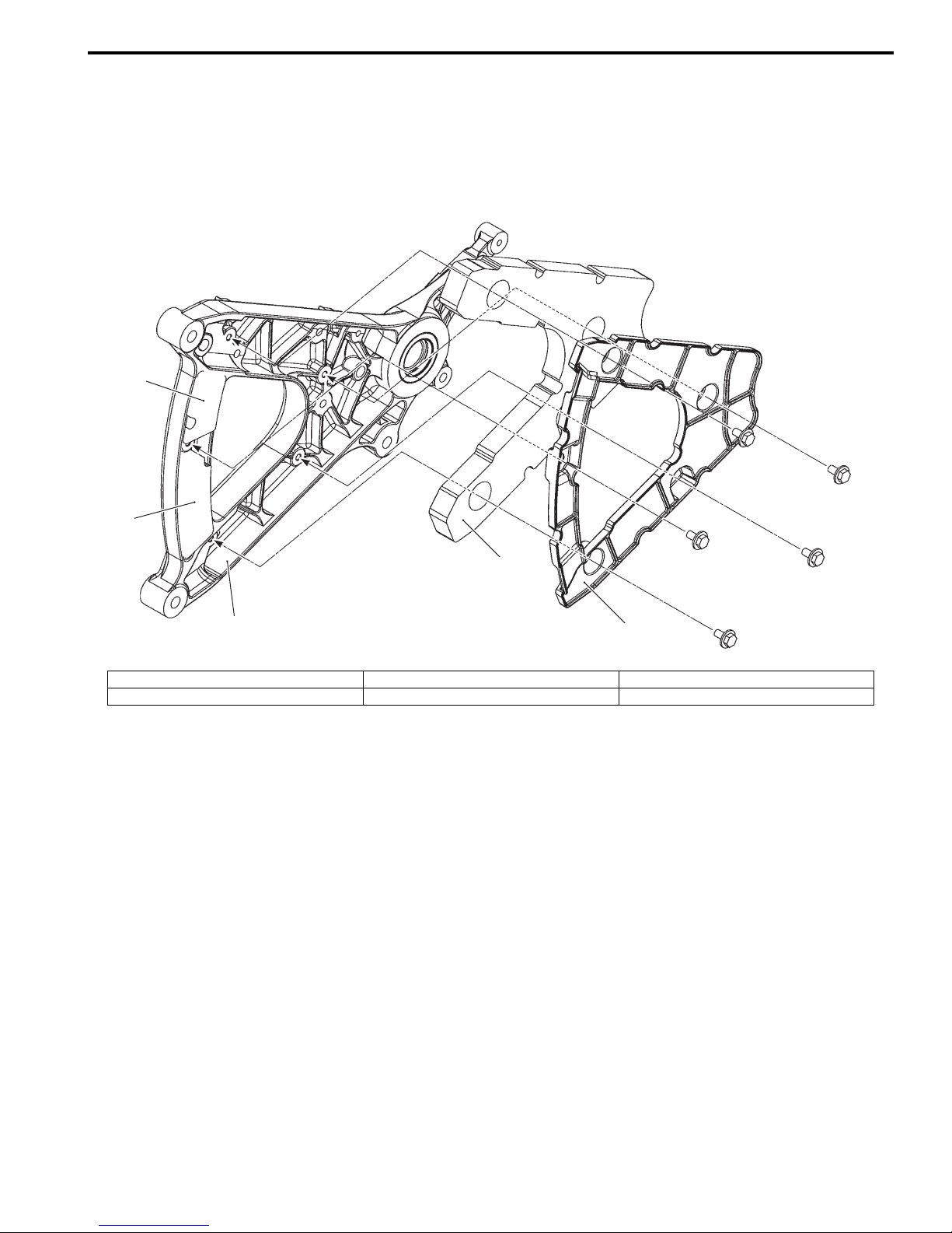
Rear Swingarm Construction (AN400/A/ZAK9)
3
2
B905H12306018
4
1
1. Rear swingarm 3. Swingarm cushion No. 2 5. Swingarm cushion cover
2. Swingarm cushion No. 3 4. Swingarm cushion No. 1
5
I905H1230001-01

2D-1 Wheels and Tires:
FWD
Suspension
Wheels and Tires
Repair Instructions
Front Wheel Components (AN400A/ZAK9)
(a)
5
8
B905H12406013
7
4
3
(b)
9
11
1
3
7
(b)
8
(c)
2
FWD
13
10
12
6
4
I905H1240001-02
1. Front wheel 6. Collar 11. Wheel balancer : 6 N⋅m (0.6 kgf-m, 4.5 lbf-ft)
2. Spacer 7. Brake disk 12. Wheel speed sensor rotor : Apply grease.
3. Bearing 8. Brake disk bolt 13. Wheel speed sensor rotor bolt : Apply thread lock to thread part.
4. Dust seal 9. Tire : 65 N⋅m (6.5 kgf-m, 47.0 lbf-ft) : Do not reuse.
5. Front axle 10. Air valve : 23 N⋅m (2.3 kgf-m, 16.5 lbf-ft)
 Loading...