

Page 1
SERVICE STATION INFORMATION
10.0 mm
ENGLISH
Fuel recommendation: Brake and clutch fluid:
See page 1-1
Engine oil recommendation: Automatic transaxle fluid:
Engine oil with “Starburst” symbol
For further details, see “Engine Oil and Filter” in the
“INSPECTION AND MAINTENANCE” section.
DOT3
An equivalent of DEXRON® -III.
Tire cold pressure:
See the “Tire Information Label” located on the
driver’s door lock pillar.
Made from 100% recycled paper,
except for cover.
99011-54G27-03EAERIO
2007
OWNER’S MANUAL
Keep With Vehicle At All Times.
Contains Important Information
On Safety, Operation & Maintenance.
Suzuki Red: Magenta 100%, Yellow 100%
Suzuki Blue: Cyan 100%, Magenta 70%
Part No. 99011-54G27-03E
June, 2006
Printed in Japan
Page 2
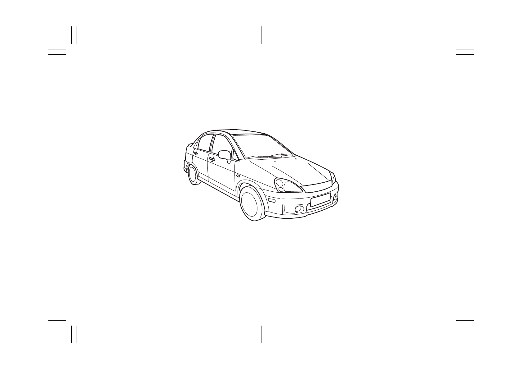
This owner’s manual applies to the AERIO series:
54G588
NOTE: The illustrated model is one of the AERIO series.
© COPYRIGHT SUZUKI MOTOR CORPORATION 2006
54G27-03E
Page 3

INTRODUCTION
Thank you for choosing SUZUKI and welcome to our growing family. Your choice was a wise o ne; SUZUKI products are a g reat value
that will give you years of driving pleasure.
This Owner’s Manual was prepared to help you have a safe, enjoyable, and trouble-free experience with your SUZUKI. In it you will learn
about the vehicle’s operation, its safety features and maintenance requirements. Please read it carefully before operating your vehicle.
Afterwards, keep this Manual in the glove box for future reference.
Should you resell the vehicle, please leave this Manual with it for the next owner.
In addition to the Owner’s Manual, the other booklets provided with your SUZUKI explain the vehi cle’s warranties. We recommend you
read them as well to familiarize yourself with this important information.
When planning the regular scheduled maintenance of your SUZUKI, we recommend you visit your local SUZUKI dealership. Their fac-
tory-trained technicians will provide the best possible service and use only genuine SUZUKI parts and accessories.
54G27-03E
Page 4
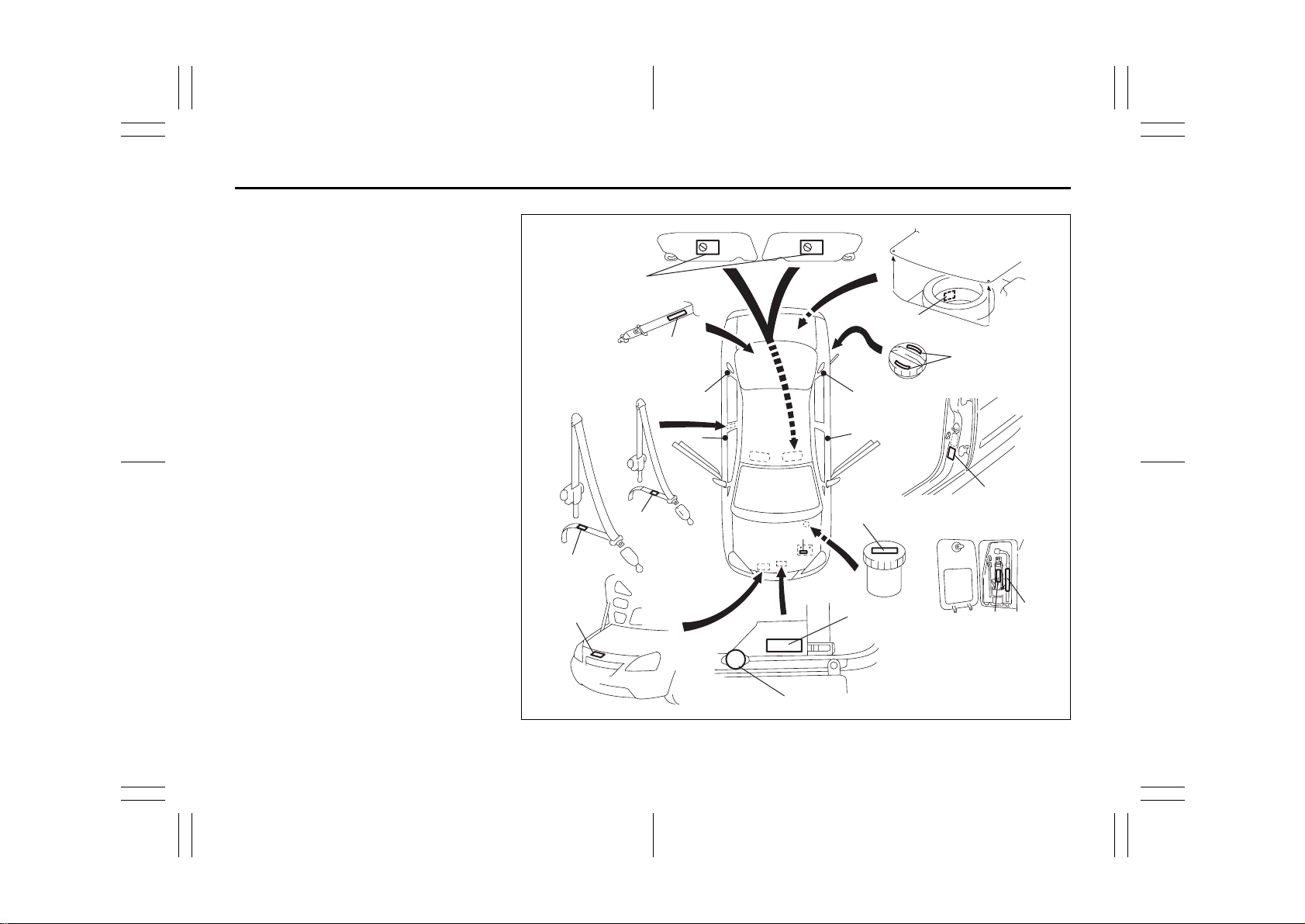
SERVICE STATION GUIDE
1. Fuel (see section 1)
2. Engine hood (see section 5)
3. Tire changing tools (see section 5)
4. Engine oil dipstick <Yellow>
(see section 9)
5. Automatic transaxle fluid dipstick
<Red> (see section 9)
6. Engine coolant (see section 9)
7. Windshield washer fluid
(see section 9)
8. Battery (see section 9)
9. Tire pressure (see tire information
label on driver’s door lock pillar)
10. Spare tire (see section 9)
(RHD)9
(RHD) 2
4
2
5
6
8
7
(LHD) 2
3
10
LHD: Left Hand Drive
RHD: Right Hand Drive
(LHD)9
1
54G637
54G27-03E
Page 5
TABLE OF CONTENTS
FUEL RECOMMENDATION 1
California Proposition 65 Warning
WARNING
Engine exhaust, some of its con stituents, and certain product components contain or emit chemicals
known to the State of California to
cause cancer and birth defects or
other reproductive harm.
BEFORE DRIVING 2
STEERING COLUMN CONTROLS 3
INSTRUMENT PANEL 4
OTHER CONTROLS AND EQUIPMENT 5
OPERATING YOUR VEHICLE 6
DRIVING TIPS 7
VEHICLE LOADING AND TOWING 8
INSPECTION AND MAINTENANCE 9
EMERGENCY SERVICE 10
APPEARANCE CARE 11
GENERAL INFORMATION 12
FUSES AND PROTECTED CIRCUITS 13
SPECIFICATIONS 14
INDEX 15
54G27-03E
Page 6
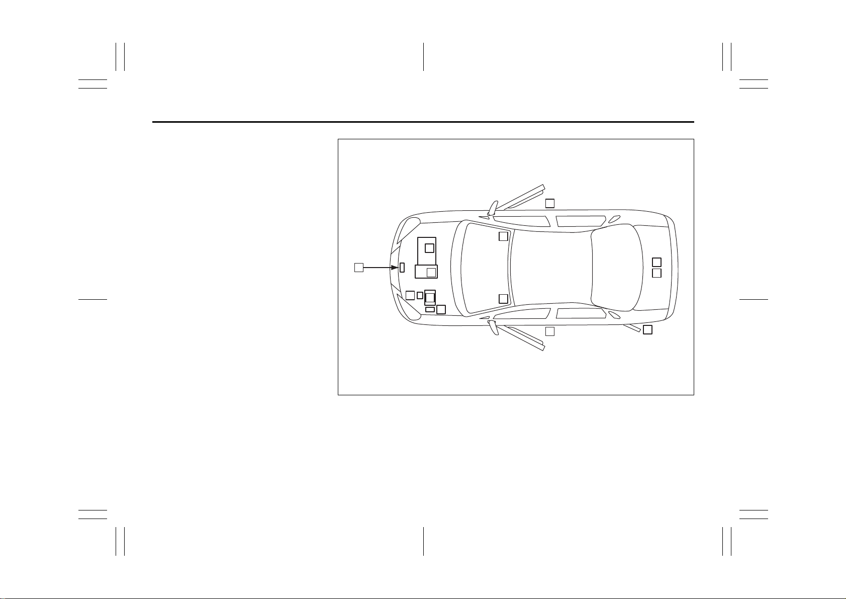
LOCATION OF WARNING
EXAMPLE
MESSAGES
Read and follow all of the warnings (labels
etc.) on your vehicle. Make sure you
understand all of them. Keep them on the
vehicle. Do not remove the messages for
any reason. If a label comes off or the
messages become difficult to be read,
have it corrected by your SUZUKI dealer.
Driver Passenger
1
12
3
6
1. Air bag warning labels
(on both sun visors)
2. Passenger seat belt warning label
3. Rear center seat belt warning label
4. Jacking warning label
5. Jacking warning label
6. Fuel filler cap message
7. Brake fluid cap message
8. Engine cooling fan warning lab e l
9. Radiator cap warning label
10. Air conditioner warning label
11. Battery label
12. Compact spare tire warning label
13. Rear outboard seat belt warning label
14. Side air bag warning label
13
14
2
11
13
10
9
13
14
14
7
8
4
5
54G633
54G27-03E
Page 7

FOREWORD
All information in this manual is based
on the latest product information available at the time of publication. Due to
improvements or other changes, there
may be discrepancies between information in this manual and your vehicle.
SUZUKI MOTOR CORPORATION
reserves the right to make production
changes at any time, without notice and
without incurring any obligation to
make the same or similar changes to
vehicles previously built or sold.
SUZUKI MOTOR CORPORATION
believes in conservation and protection of
Earth’s natural resources.
To that end, we encourage every vehicle
owner to recycle, trade in, or properly dispose of, as appropriate, used motor oil,
coolant, and other fluids, batteries and
tires.
IF YOU HAVE ANY PROBLEMS WITH
YOUR SUZUKI:
Please review the New Vehicle Warranty
Information booklet supplied with your
SUZUKI. Should you have a question or
problem regarding the warranty or service
of your vehicle, please take the following
action:
Consult the Service Manager and the
Owner of the Suzuki Automotive Dealership. Explain your problem and ask for
their assistance in resolving your problem.
The Owner of the dealership is in the very
best position to assist you as he or she is
vitally concerned with your continued satisfaction.
If you are still in need of additional information, or if you are dissatisfied, request that
your dealer arrange a meeting with your
District Service Manager.
If, after doing so, you still require further
assistance, and you purchased your
SUZUKI in the continental United States,
please contact the American Suzuki Customer Relations Department by telephone
at 1-800-934-0934 or in writing at:
American Suzuki Motor Corporation
Automotive Customer Relations
3251 East Imperial Highway
Brea, CA 92821-6795
If you purchased your SUZUKI in Canada
please contact the Suzuki Canada Customer Relations Department by telephone
at 1-905-889-2677 extension 2254 or in
writing at:
Suzuki Canada Inc.
Customer Relations
100 East Beaver Creek Road
Richmond Hill, On
L4B 1J6
In the event you require assistance related
to your SUZUKI, while temporarily travelling in either the United States or Canada,
you may wish to contact the Suzuki Customer Relations Department directly of the
country in which you are temporarily operating your vehicle.
Please be certain to provide us with the following information: the model, Vehicle
Identification Number, mileage, accessories involved, event dates, your concern,
and any other comments which you may
have. When we receive your correspondence, we will be pleased to contact the
Owner of your dealership and assist in
resolving your concern.
For owners outside the continental United
States, please refer to the distributor’s
address listed in your Warranty Information
booklet.
0-1
54G27-03E
Page 8
IMPORTANT
WARNING/CAUTION/NOTE
Please read this manual and follow its
instructions carefully. To emphasize special information, the symbol and the
words WARNING, CAUTION and NOTE
have special meanings. Pay special attention to the messages highlighted by these
signal words:
WARNING
Indicates a potential hazard that
could result in death or injury.
CAUTION
Indicates a potential hazard that
could result in vehicle damage.
NOTE:
Indicates special information to make
maintenance easier or instructions clearer.
75F135
The circle with a slash in this manual
means “Don’t do this” or “Don’t let this happen”.
MODIFICATION WARNING
WARNING
Do not modify this vehicle. Modification could adversely affect safety,
handling, performance or durability
and may violate governmental regulations. In addition, damage or performance problems resulting from
modification may not be covered
under warranty.
CAUTION
Improper installation of mobile communication equipment such as cellular telephones or CB (Citizen’s B and)
radios may cause electronic interference with your vehicle’s ignition system, resulting in vehicle performance
problems. Consult your SUZUKI
dealer or qualified service technician
for advice on installing such mobile
communication equipment.
0-2
54G27-03E
Page 9

LEAK DETECTION PUMP
NOTE:
Your vehicle has a pump to regularly check
the vehicle’s evaporative emission control
system for leaks. This check is performed
approximately five hours after the engine is
turned off. During this leak check, you may
hear a sound coming from the vehicle for
several minutes. This sound is normal and
does not indicate a malfunction.
0-3
54G27-03E
Page 10

MEMO
0-4
54G27-03E
Page 11
FUEL RECOMMENDATION
65D394
FUEL RECOMMENDATION
Fuel Recommendation ........................................................1-1
1
54G27-03E
Page 12
Fuel Recommendation: 1, 2
FUEL RECOMMENDATION
Fuel Recommendation
60A004
Your vehicle requires regular unleaded
gasoline with a minimum rating of 87 pump
octane ((R + M)/2 method). In some areas,
the only fuels that are available are oxygenated fuels.
Oxygenated fuels which meet the minimum octane requirement and the requirements described below may be used in
your vehicle without jeopardizing the New
Vehicle Limited Warranty.
NOTE:
Oxygenated fuels are fuels which contain
oxygen-carrying additives such as MTBE
or alcohol.
Gasoline Containing MTBE
Unleaded gasoline containing MTBE
(methyl tertiary butyl ether) may be used in
your vehicle if the MTBE content is not
greater than 15%. This oxygenated fuel
does not contain alcohol.
Gasoline/Ethanol blends
Blends of unleaded gasoline and ethanol
(grain alcohol), also known as gasohol,
may be used in your vehicle if the ethanol
content is not greater than 10%.
Gasoline/Methanol blends
Fuels containing 5% or less methanol
(wood alcohol) may be suitable for use in
your vehicle if they contain cosolvents and
corrosion inhibitors. Do NOT USE fuels
containing more than 5% methanol under
any circumstances. Fuel system damage
or vehicle performance problems resulting
from the use of such fuels are not the
responsibility of SUZUKI and may not be
covered under the New Vehicle Limited
Warranty.
Fuel Pump Labeling
In some states, pumps that dispense oxygenated fuels are required to be labeled for
the type and percentage of oxygenate and
whether important additives are present.
Such labels may provide enough information for you to determine if a particular
blend of fuel meets the requirements listed
above. In other areas, pumps may not be
clearly labeled as to the content or type of
oxygenate and additives. If you are not
sure that the fuel you intend to use meets
these requirements, check with the service
station operator or the fuel supplier.
NOTE:
To help clean the air, SUZUKI recommends you use the oxygenated fuels.
However, if you are not satisfied with the
driveability or fuel economy of your vehicle
when you are using an oxygenated fuel,
switch back to the regular unleaded gasoline.
CAUTION
Be careful not to spill fuel containing
alcohol while refueling. Fuels containing alcohol can cause paint damage, which is not covered under the
New Vehicle Limited Warranty.
1-1
54G27-03E
Page 13
BEFORE DRIVING
BEFORE DRIVING
60G404
Keys ......................................................................................2-1
Door Locks ..........................................................................2-1
Windows ..............................................................................2-8
Mirrors ..................................................................................2-10
Seat Adjustment ..................................................................2-11
Head Restraints ................................................................... 2-12
Seat Belts and Child Restraint Systems ........................... 2-13
Supplemental Restraint System (air bags) ....................... 2-32
2
54G27-03E
Page 14
Keys: 8
Door Locks: 3, 5, 8
BEFORE DRIVING
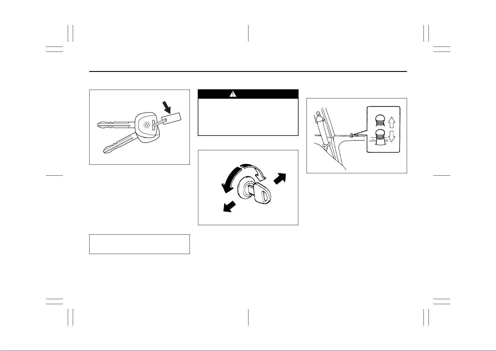
Keys
EXAMPLE
54G489
Your vehicle comes with a pair of identical
keys. Keep the spare key in a safe place.
One key can open all of the locks on the
vehicle.
The key identification number is stamped
on a metal tag provided with the keys.
Keep the tag in a safe place. If you lose
your keys, you will need this number to
have new keys made. Write the number
below for your future reference.
KEY NUMBER:
Ignition Key Reminder
A buzzer sounds to remind you to remove
the ignition key if it is in the ignition switch
when the driver’s door is opened.
Door Locks
WARNING
Always lock all doors when driving.
Locking the doors helps to prevent
occupants from being thrown from
the vehicle in the event of an accident. It also helps prevent unintended opening of the doors.
Side Door Locks
LOCK
UNLOCK
Rear
Front
60A009
To lock a front door from outside the vehicle:
• Insert the key and turn the top of the key
toward the rear of the vehicle, or
• Push in the lock knob and close the
door.
To unlock a front door from outside the
vehicle, insert the key and turn the top of
the key toward the front of the vehicle.
EXAMPLE
UNLOCK
LOCK
54G005
To lock a door from inside the vehicle, push
down the lock knob. Pull up the lock knob
to unlock the door.
To lock a rear side door from outside the
vehicle, push in the lock knob and close
the door.
2-1
54G27-03E
Page 15
Door Locks: 3, 5, 8
BEFORE DRIVING
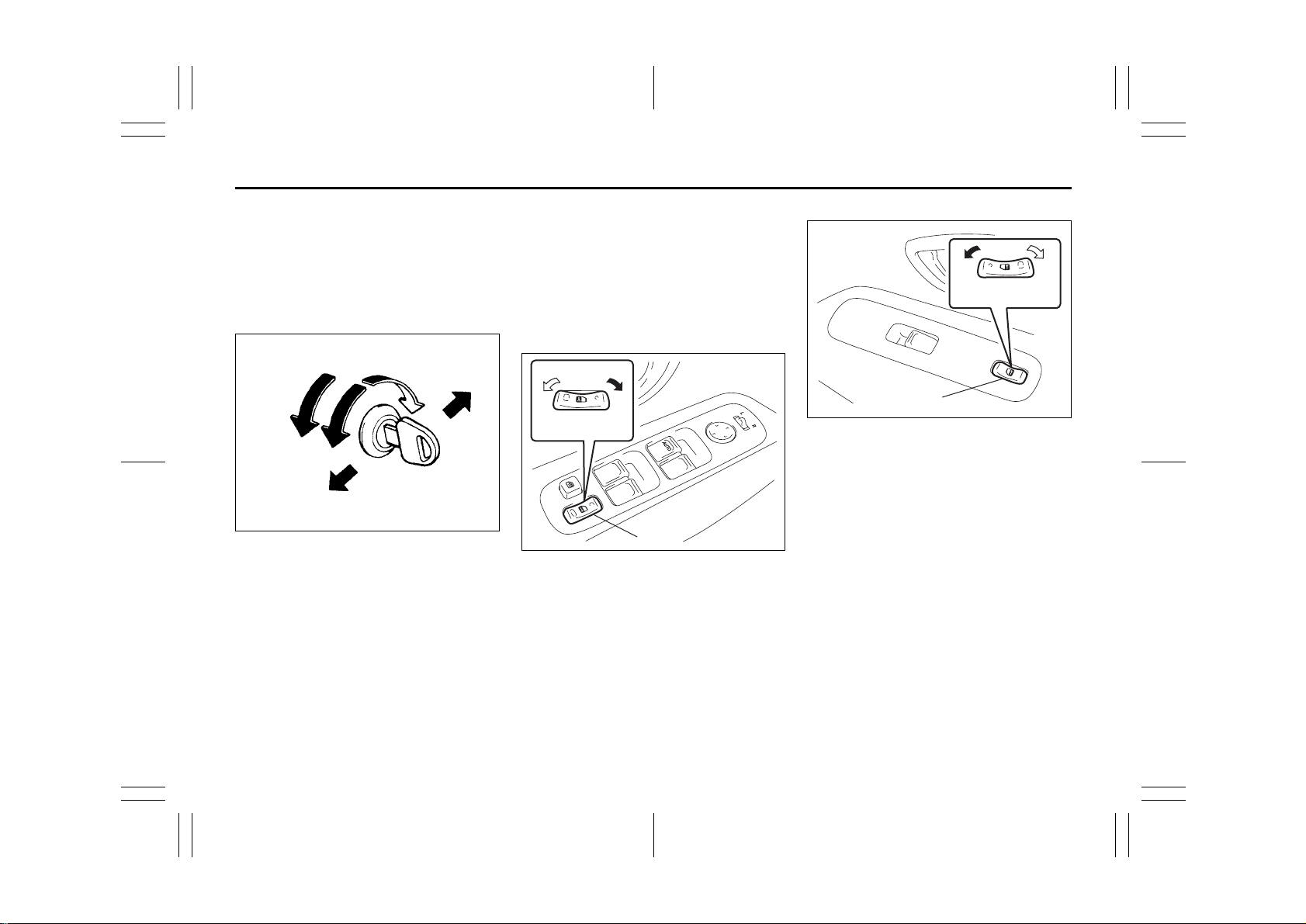
Power Door Locking System
(if equipped)
You can lock and unlock all the doors
simultaneously by:
• Turning the key in a front door lock, or
• Pushing the power door locking switch
located on the driver’s side or the front
passenger’s side door panel.
UNLOCK
Front
(when using the key)
To lock all the doors simultaneously, insert
the key in a front door lock and turn the top
of the key toward the rear of the vehicle
once.
LOCK
Rear
54G294
To unlock all the doors simultaneously,
insert the key in a front door lock and turn
the top of the key toward the front of the
vehicle twice.
To unlock only one of the front doors, insert
the key in that door lock and turn the top of
the key toward the front of the vehicle
once.
Driver’s side
UNLOCK LOCK
(1)
65D465
Front passenger’s side
UNLOCKLOCK
(2)
52D161
(when using the power door locking
switch)
To lock or unlock all the doors simultaneously, depress the front or rear of the
switch (1) or (2), respectively.
2-2
54G27-03E
Page 16
Door Locks: 3, 5, 8
BEFORE DRIVING
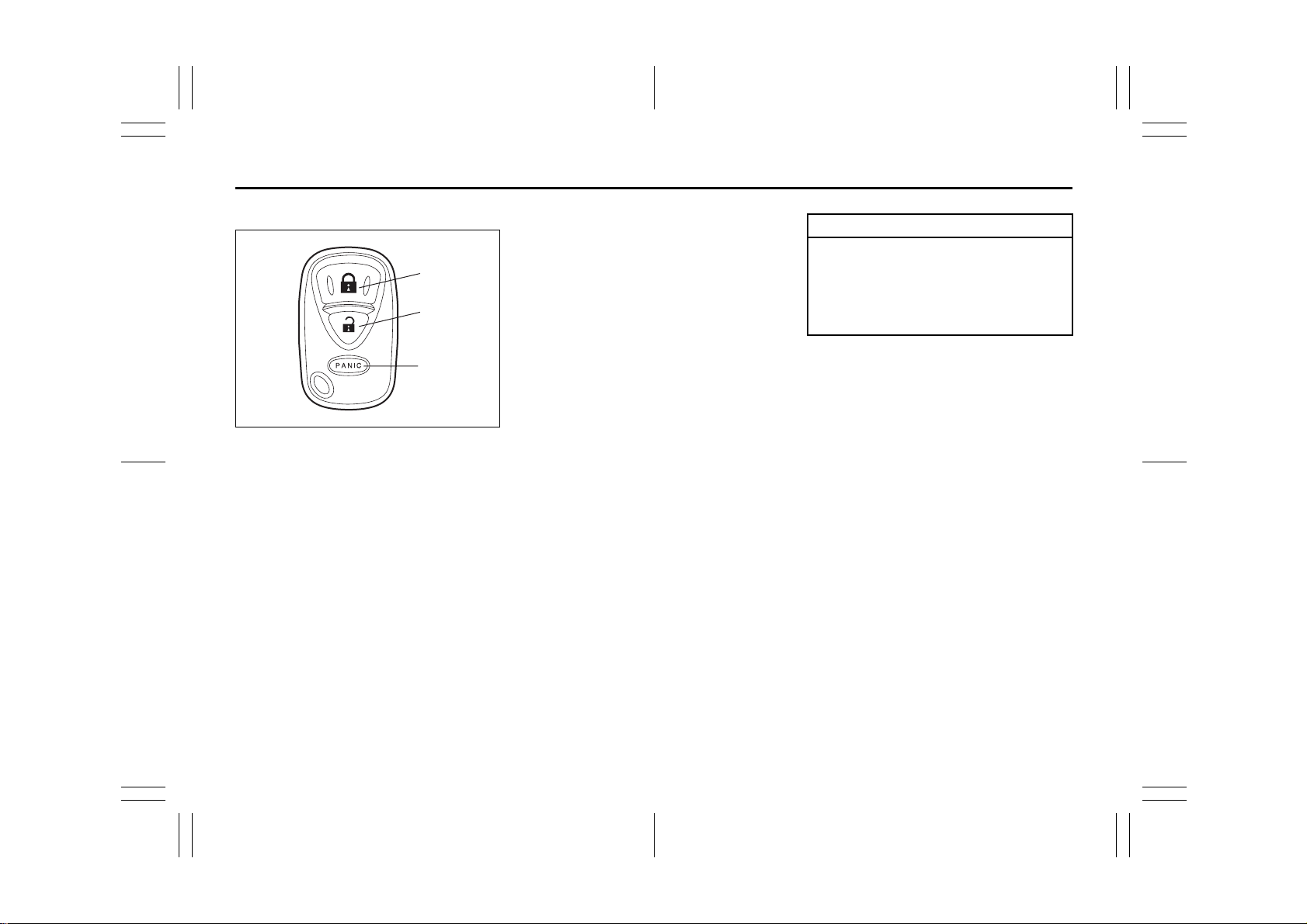
Keyless Entry System (if equipped)
(1)
(2)
(3)
52D209
(1) “LOCK” button
(2) “UNLOCK” button
(3) “PANIC” button
You can lock or unlock all doors simultaneously by operating the transmitter near
the vehicle.
• To lock the doors, push the “LOCK” button on the transmitter.
• To unlock the driver’s door, push the
“UNLOCK” button on the transmitter
once.
• To unlock other doors, wait a second or
two, then push the “UNLOCK” button a
second time. If you “double-click” too
fast, the doors will not unlock.
When the doors are locked, the turn signal
lights will flash once.
When the door(s) is(are) unlocked:
• The turn signal lights will flash twice.
• If the interior light switch is in the midd le
position, the interior light will turn on for
about 15 seconds and then fade out. If
you insert the key into the ignition switch
during this time, the light will start to fade
out immediately.
Be sure the doors are locked after you
operate the “LOCK” button. If no door is
opened within about 30 seconds after the
“UNLOCK” button is operated, the doors
will automatically lock again.
NOTE:
• The maximum operating distance is
about 5 m (16 ft.), but this can vary
depending on the surroundings, especially near other transmitting devices
such as radio towers or CB (Citizen’s
Band) radios.
• The door locks can not be operated with
the transmitter if the ignition key is
inserted in the ignition switch.
• If you lose one of the transmitters, ask
your SUZUKI dealer as soon as possible
for a replacement and to have the lost
one deactivated, or perform the programming procedure yourself.
CAUTION
The transmitter is a sensitive electronic instrument. To avoid damaging
the transmitter, do not expose it to
impacts, moisture or high temperature (such as on the dashboard under
direct sunlight).
“PANIC” button function
This function is to get the attention of others.
Press the “PANIC” button for more than 1
second. The headlights, parking lights, and
taillights will blink for about 30 seconds.
Also, the horn will sound intermittently for
about 30 seconds at the same time.
To cancel the “PANIC” mode, press any
button (PANIC, LOCK or UNLOCK) on the
transmitter. You can also insert the key in
the ignition switch and turn to the “ON”
position to cancel the “PANIC” mode.
NOTE:
The “PANIC” button function will not activate when the key is in the ignition switch.
2-3
54G27-03E
Page 17
Door Locks: 3, 5, 8
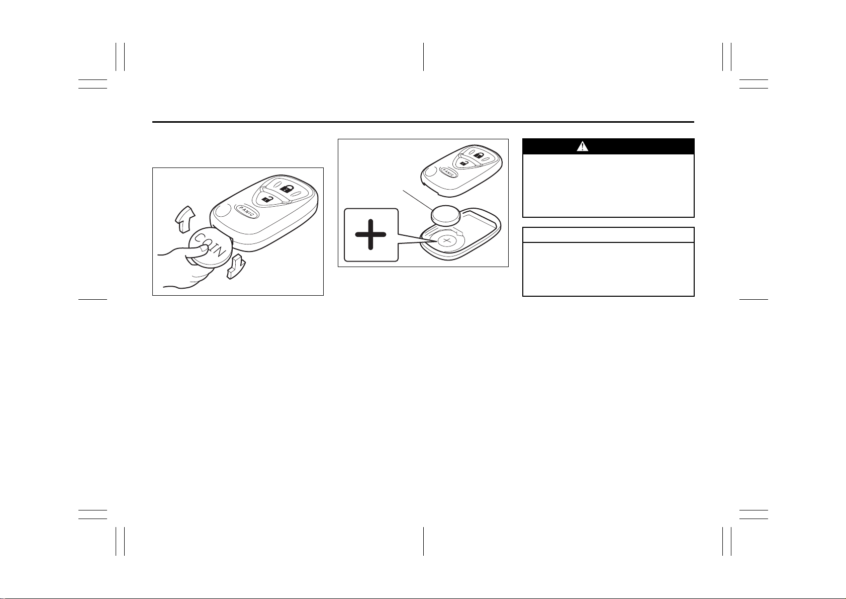
Replacement of the transmitter battery
If the transmitter becomes unreliable,
replace the battery.
1) Put the edge of a coin or a flat blade
screw driver in the slot of the transmitter
and pry it open.
52D210
(1)
52D211
2) Replace the battery (1) (Lithium disctype CR2025 or equivalent) so its + terminal faces the “+” mark of the transmitter.
3) Close the transmitter firmly.
4) Make sure the door locks can be operated with the transmitter.
5) Dispose of the used battery properly
according to applicable rules or regulations. Do not dispose of lithium batteries with ordinary household trash.
BEFORE DRIVING
WARNING
Swallowing a lithium battery may
cause serious internal injury. Do not
allow anyone to swallow a lithium
battery. Keep lithium batteries away
from children and pets. If swallowed,
contact a physician immediately.
CAUTION
The transmitter is a sensitive electronic instrument. To avoid damaging
the transmitter, do not expose it to
dust or moisture or tamper with internal parts.
2-4
54G27-03E
Page 18
Door Locks: 3, 5, 8
BEFORE DRIVING
Programming/Removing the transmitter code yourself
Your new vehicle was originally equipped
with two transmitters.
If you have lost one of the transmitters, you
should change the transmitter code in your
vehicle’s memory as soon as possible for
security. If you purchase additional transmitters, the new transmitters need to be
programmed into your vehicle’s memory.
You can perform this yourself by using the
following procedure:
NOTE:
• You can program up to four transmitter
codes into your vehicle’s memory. The
four codes may be the same or different.
• If you try to program a fifth code, the oldest code will be cleared automatically.
• To purchase new transmitters, see your
SUZUKI dealer.
• Before you begin programming, have all
of your transmitters available.
To program the new transmitter
1) Confirm that all the doors are closed
and the ignition key is out of the ignition
cylinder.
2) Open the driver’s door.
3) Insert the key, turn the ignition switch to
the “ON” position, turn the ignition
switch to the “OFF” position and
remove the key within 10 seconds.
(1)
54G404
4) Push and release the driver’s door
switch (1) 3 times, insert the key, and
turn the ignition switch to the “ON” position within 20 seconds.
5) Turn the ignition switch to the “OFF”
position and remove the key within 10
seconds. All doors will lock/unlock to
confirm that this process has been
properly done.
(2)
52D212
6) Press the “UNLOCK” button (2) on the
transmitter one time within 20 seconds
(after step 5). All the doors will lock/
unlock to confirm that the process has
been completed and the transmitter has
been programmed.
7) If you want to program an additional
transmitter, repeat the procedure from
step 1) through step 6).
8) Make sure that the keyless entry system operates properly by operating
each transmitter.
2-5
54G27-03E
Page 19
Door Locks: 3, 5, 8
BEFORE DRIVING
To change the old transmitter codes in
your vehicle’s memory
If you have lost one of the transmitters, you
should change the transmitter codes in
your vehicle’s memory as soon as possible
for security.
To remove one of the transmitter codes
from your vehicle’s memory, first replace all
three of the transmitter codes in your vehicle’s memory, then program additional
transmitters as follows:
1) Program one of your transmitters four
times, by repeating the programming
procedure shown in this section. This
will replace all the old transmitter codes
in the vehicle’s memory with the code
for the transmitter you are using.
2) If you want to program up to two additional transmitters, repeat the programming procedure shown in this section.
3) Make sure that the keyless entry system operates properly by operating
each transmitter.
1. For USA
This device complies with Part 15 of the
FCC Rules. Operation is subject to the following two conditions:
1) this device may not cause harmful interference, and
2) this device must accept any interference received, including interference
that may cause undesired operation.
NOTE:
Changes or modifications not expressly
approved by the party responsible for compliance could void the user’s authority to
operate the equipment.
2. For Canada
This device complies with Industry Canada
Standard RSS-210. Operation is subject to
the following two conditions:
1) this device may not cause interference,
and
2) this device must accept any interference, including interference that may
cause undesired operation of the
device.
The term “IC:” before the certification/registration number only signifies that the
Industry Canada technical specifications
were met.
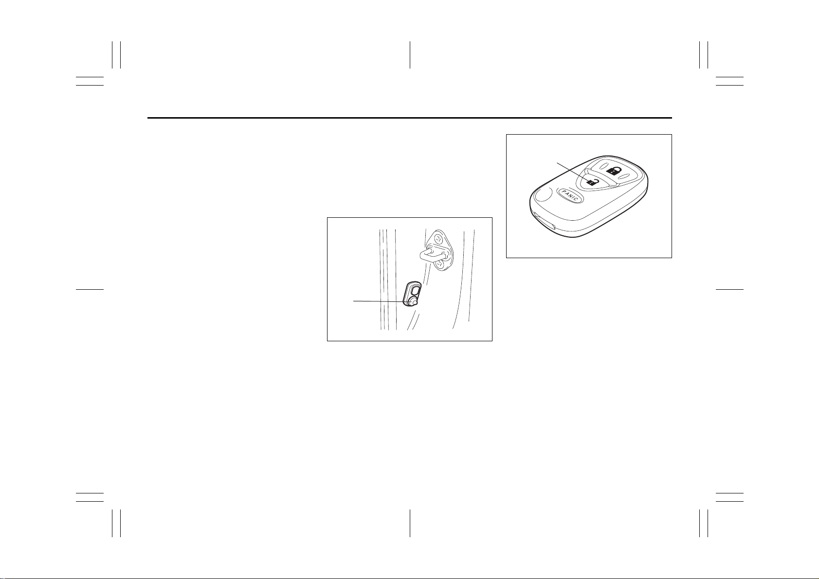
Child Lock System (rear side doors)
EXAMPLE
(2)
(1)
54G574
Each of the rear side doors is equipped
with a child lock which can be used to help
prevent unwanted opening of the door from
inside the vehicle. When the lock lever is in
the “LOCK” position (1), the rear side door
can only be opened from outside. When
the lock lever is in the “UNLOCK” position
(2), the rear side door can be opened from
inside or outside.
WARNING
Be sure to place the child lock in the
“LOCK” position whenever children
are seated in the rear.
2-6
54G27-03E
Page 20
Door Locks: 3, 5, 8
BEFORE DRIVING
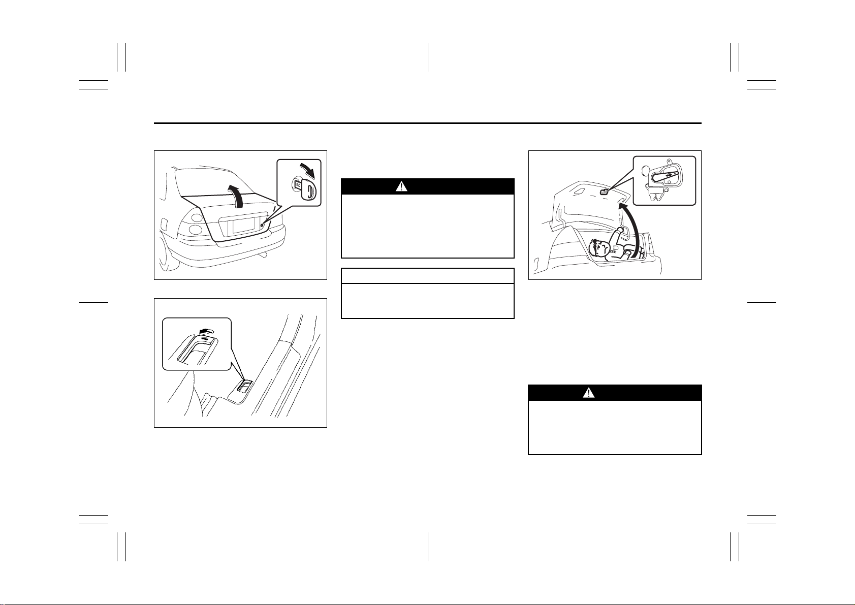
Trunk Lid
54G287
EXAMPLE
54G495
To unlock the lid, insert the key and turn it
clockwise. You can also unlock the lid by
pulling the release lever (if equipped)
located to the outboard side of the driver’s
seat.
To lock the lid, lower the lid and press
down on it. The lid is locked automatically.
WARNING
Always make sure that the trun k li d is
closed and latched securely. Otherwise, it may open unexpectedly while
driving. Also completely closing it
helps keep exhaust gases from entering the car.
CAUTION
Do not use the key to lift up the trunk
lid, or the key may break off in the
lock.
Internal Trunk Release
EXAMPLE
54G297
There is a release lever located inside the
trunk, on the rear part of the trunk lid. This
lever is for emergency use so that if a person, such as a child, gets trapped in the
trunk compartment, he can exit the vehicle.
The lever glows in the dark, after a brief
exposure to ambient light, so it can be
found easily. It is operated by pushing it
down in the direction of the arrow.
WARNING
To help avoid situations where someone might get trapped in the trunk,
keep your vehicle locked when unattended, and do not allow anyone to
play in the trunk.
2-7
54G27-03E
Page 21
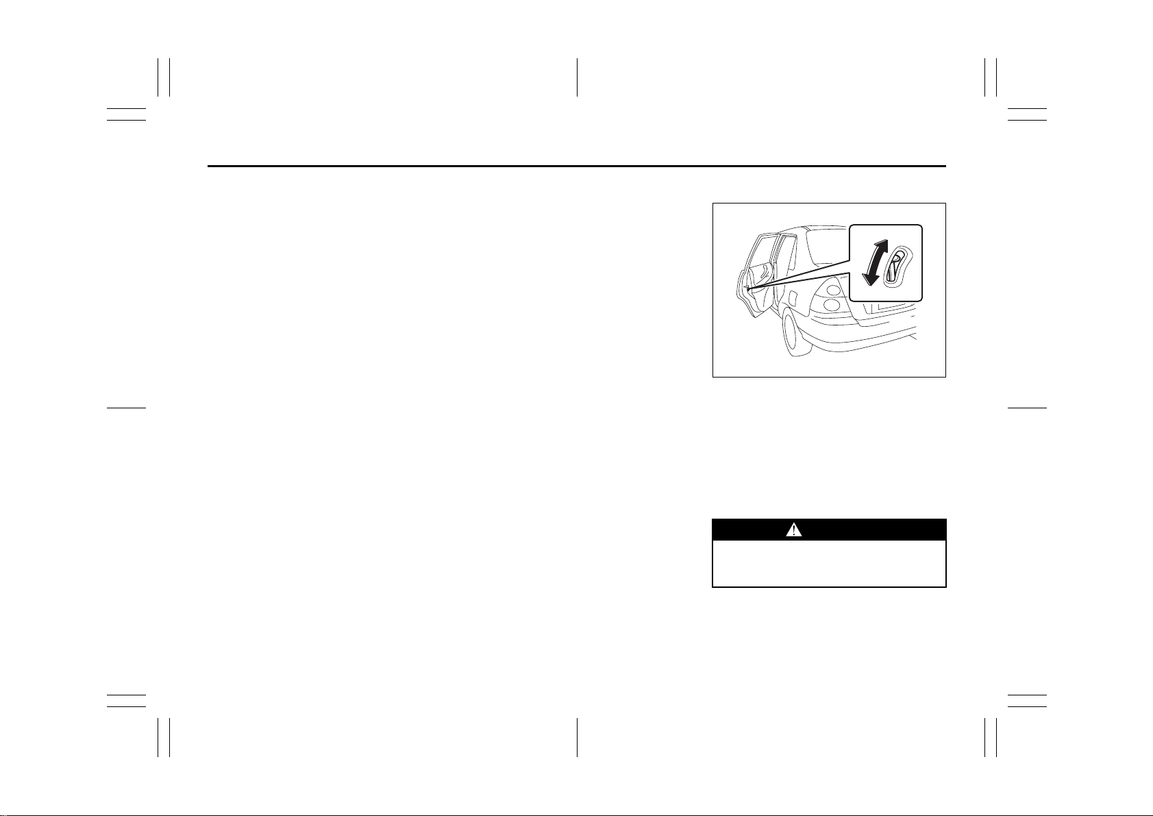
Windows: 3, 8
BEFORE DRIVING
Windows
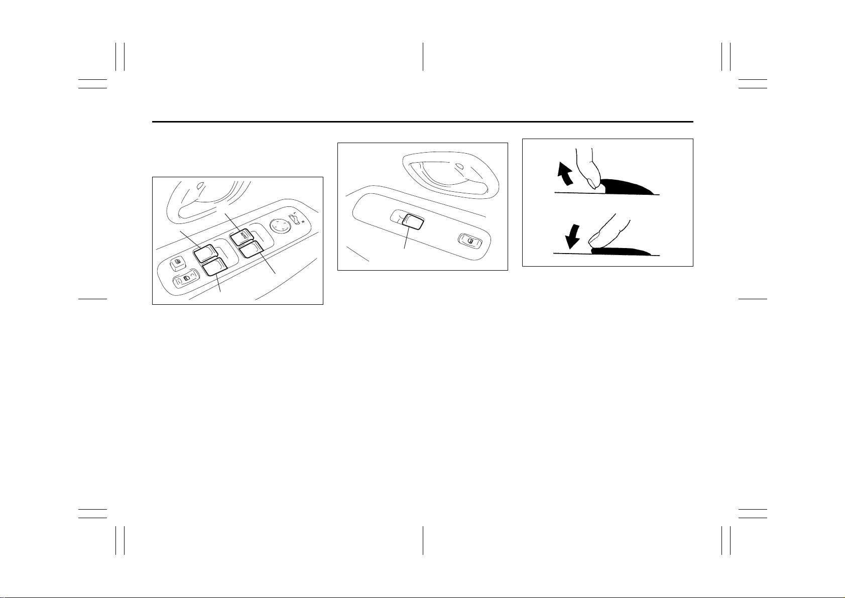
Power Window Controls
Driver’s side
(1)
(4)
(2)
(5)
65D467
The power windows can only be operated
when the ignition switch is in the “ON” position.
The driver’s door has switches (1), (2), (4),
(5), to operate the driver’s window, the
front passenger’s window, the rear left window and the rear right window, respectively.
Passenger’s door
EXAMPLE
(3)
52D162
The passenger’s door only has a switch to
operate the passenger’s window (3).
CLOSE
OPEN
81A009
To open a window, push the top part of the
switch and to close a window lift up the top
part of the switch.
The driver’s window has an auto-down feature for added convenience (at toll booths
or drive-through restaurants, for example).
This means you can open the window without holding the window switch in the
“Down” position. Press the driver’s window
switch completely down and release it. To
stop the window before it reaches the bottom, pull the switch up briefly.
2-8
54G27-03E
Page 22
Windows: 3, 8
BEFORE DRIVING
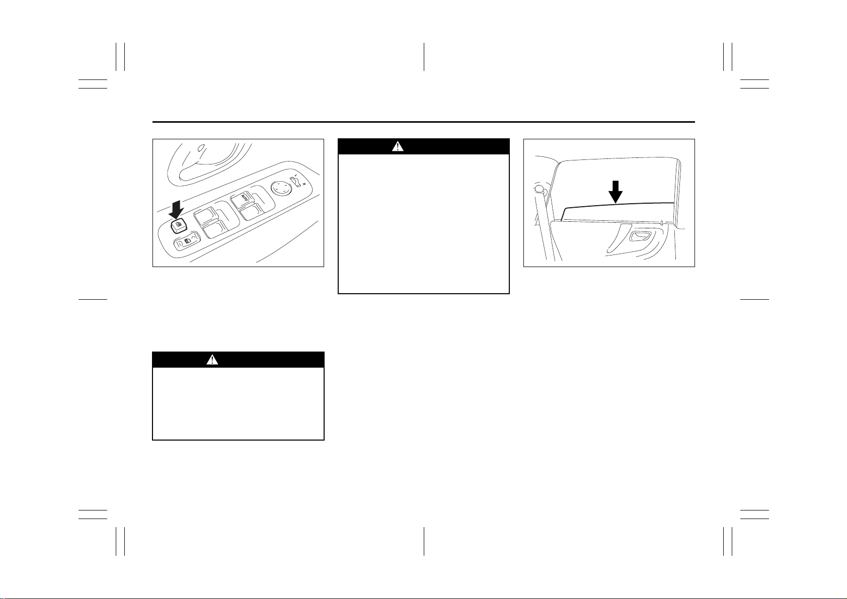
65D469
The driver’s door also has a lock switch for
the passenger’s window. When you push in
the lock switch, the passenger’s window
can not be raised or lowered by operating
any of the switches (2), (3), (4) or (5). To
restore normal operation, release the lock
switch by pushing the switch again.
WARNING
• You should always lock the passenger’s window operation when there
are children in the vehicle. Children
can be seriously injured if they get
part of their body caught by the
window during operation.
(Continued)
WARNING
(Continued)
• To avoid injuring an occupant by
window entrapment, be sure no
part of the occupant’s body such
as hands or head is in the path of
the electric windows when closing
them.
• Always remove the ignition key
when leaving the vehicle even if a
short time. Also do not leave children alone in a parked vehicle.
Unattended children could use the
electric window switches and get
trapped by the window.
EXAMPLE
54G011
NOTE:
The rear side door windows are not
designed to open fully. They can be
opened about 2/3 of the way down.
2-9
54G27-03E
Page 23
Windows: 3, 8
Mirrors: 3, 8
BEFORE DRIVING
Mirrors
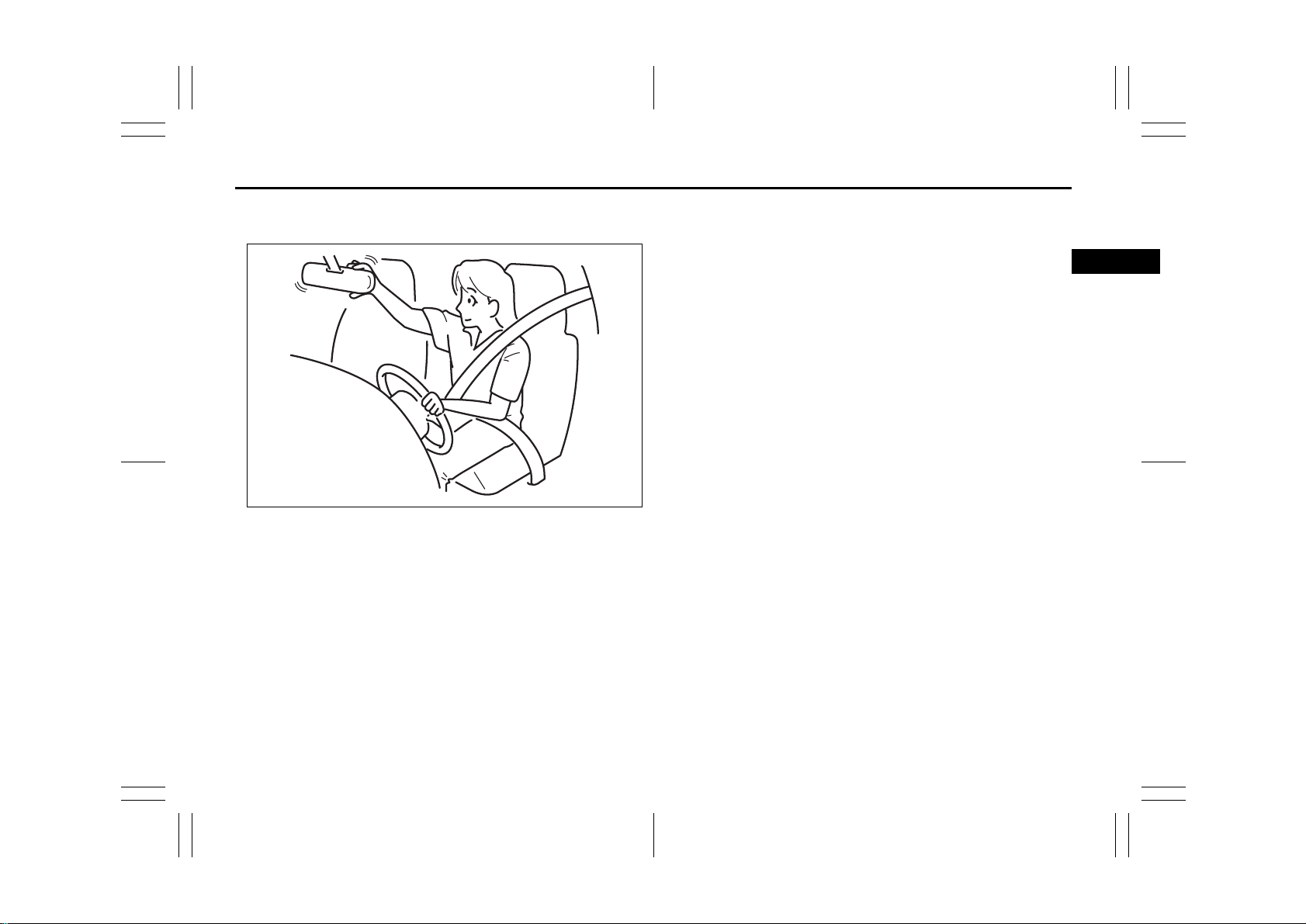
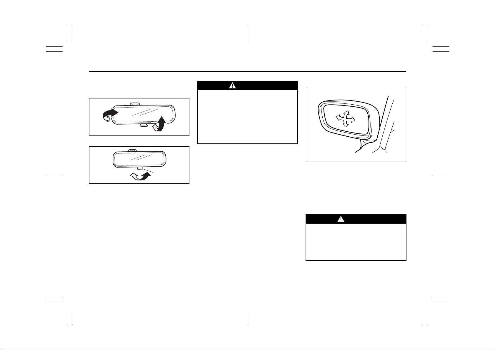
Inside Rearview Mirror
65D410
(1)
Day driving Night driving
65D409
You can adjust the inside rearview mirror
by hand so as to see the rear of your ve hicle in the mirror. To adjust the mirror, set
the selector tab (1) to the day position,
then move the mirror up, down or sideways
by hand to obtain the best view.
When driving at night, you can move the
selector tab to the night position to reduce
glare from the headlights of vehicles
behind you.
WARNING
Outside Rearview Mirrors
• Always adjust the mirror with the
selector set to the day position.
• Only use the night position if it is
necessary to reduce glare from the
headlights of vehicles behind you.
Be aware that in this position you
may not be able to see some
objects that could be seen in the
day position.
54G012
Adjust the outside rearview mirrors so you
can just see the side of your vehicle in the
mirrors.
The passenger’s side mirror is a convex
(curved surface) mirror. Objects seen in
this mirror will look smaller and appear farther away than when seen in a flat mirror.
WARNING
Be careful when judging the size or
distance of a vehicle or other object
seen in the side convex mirror. Be
aware that objects look smaller and
appear farther away than when seen
in a flat mirror.
2-10
54G27-03E
Page 24
Mirrors: 3, 8
Seat Adjustment: 3
BEFORE DRIVING
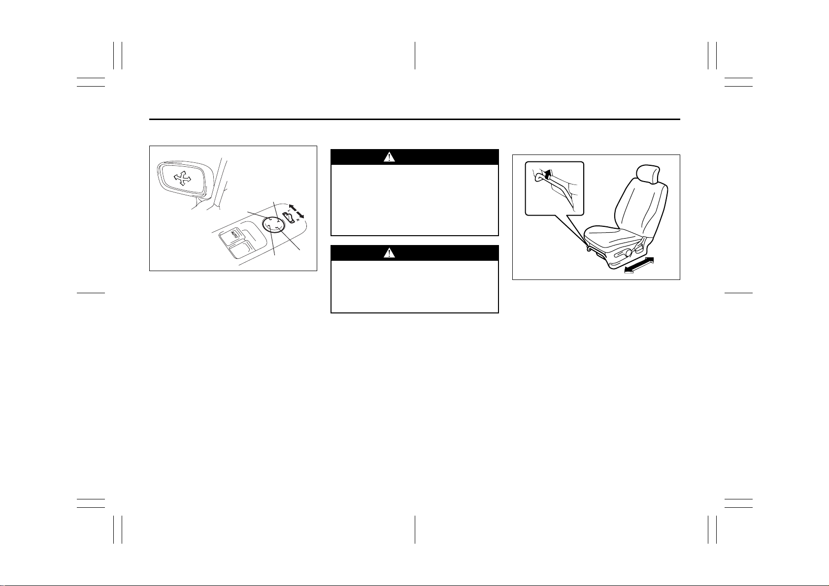
Power Mirror Control (if equipped)
(1)
(3)
(2)
(4)
(3)
The switch to control the power rearview
mirrors is located on the driver’s door
panel. You can adjust the mirrors when the
ignition switch is in the “ACC” or “ON” position. To adjust the mirrors:
1) Move the selector switch to the left or
right to select the mirror you wish to
adjust.
2) Press the outer part of the switch that
corresponds to the direction you wish to
move the mirror.
3) Return the selector switch to the center
position to help prevent unintended
adjustment.
(1)
(4)
(2)
54G478
Seat Adjustment
WARNING
Never attempt to adjust the driver’s
seat or seatback while driving. The
seat or seatback could move unexpectedly, causing loss of control.
Make sure that the driver’s seat and
seatback are properly adjusted
before you start driving.
WARNING
To avoid excessive seat belt slack,
which reduces the effectiveness of
the seat belts as a safety device,
make sure that the seats are adjusted
before the seat belts are fastened.
Adjusting Seat Position
Front seat
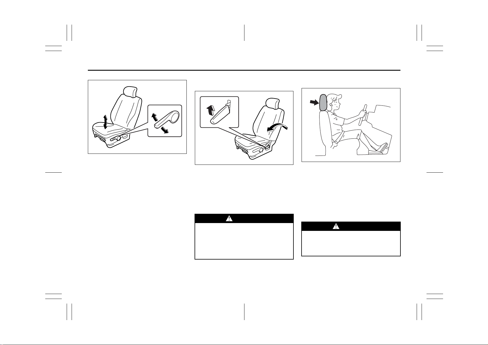
54G470
The adjustment lever for each front seat is
located under the front of the seat. To
adjust the seat position, pull up on the
adjustment lever and slide the seat forward
or rearward. After adjustment, try to move
the seat forward and rearward to ensure
that it is securely latched.
2-11
54G27-03E
Page 25
Seat Adjustment: 3
BEFORE DRIVING
54G471
If the driver’s seat is equipped with a seat
height adjuster lever on the outboard side
of the seat, raise or lower the seat by pulling up or down the adjuster lever.
Adjusting Seatbacks
Front seat
54G472
To adjust the seatback angle of front seats,
pull up the lever on the outboard side of
the seat, move the seatback to the desired
position, and release the lever to lock the
seatback in place. After adjustment, try
moving the seatback to make sure it is
securely locked.
WARNING
All seatbacks should always be in an
upright position when driving, or seat
belt effectiveness may be reduced.
Seat belts are designed to offer maximum protection when seatbacks are
in the upright position.
Head Restraints
75F123
Head restraints are designed to help
reduce the risk of neck injuries in case of
an accident.
Adjust the head restraint to the position
which places the center of the head
restraint closest to the top of your ears. If
this is not possible for very tall passengers,
adjust the head restraint as high as possible.
WARNING
• Never drive the vehicle with the
head restraints removed.
• Do not attempt to adjust the head
restraint while driving.
2-12
54G27-03E
Page 26
Seat Adjustment: 3
Head Restraints: 3
BEFORE DRIVING
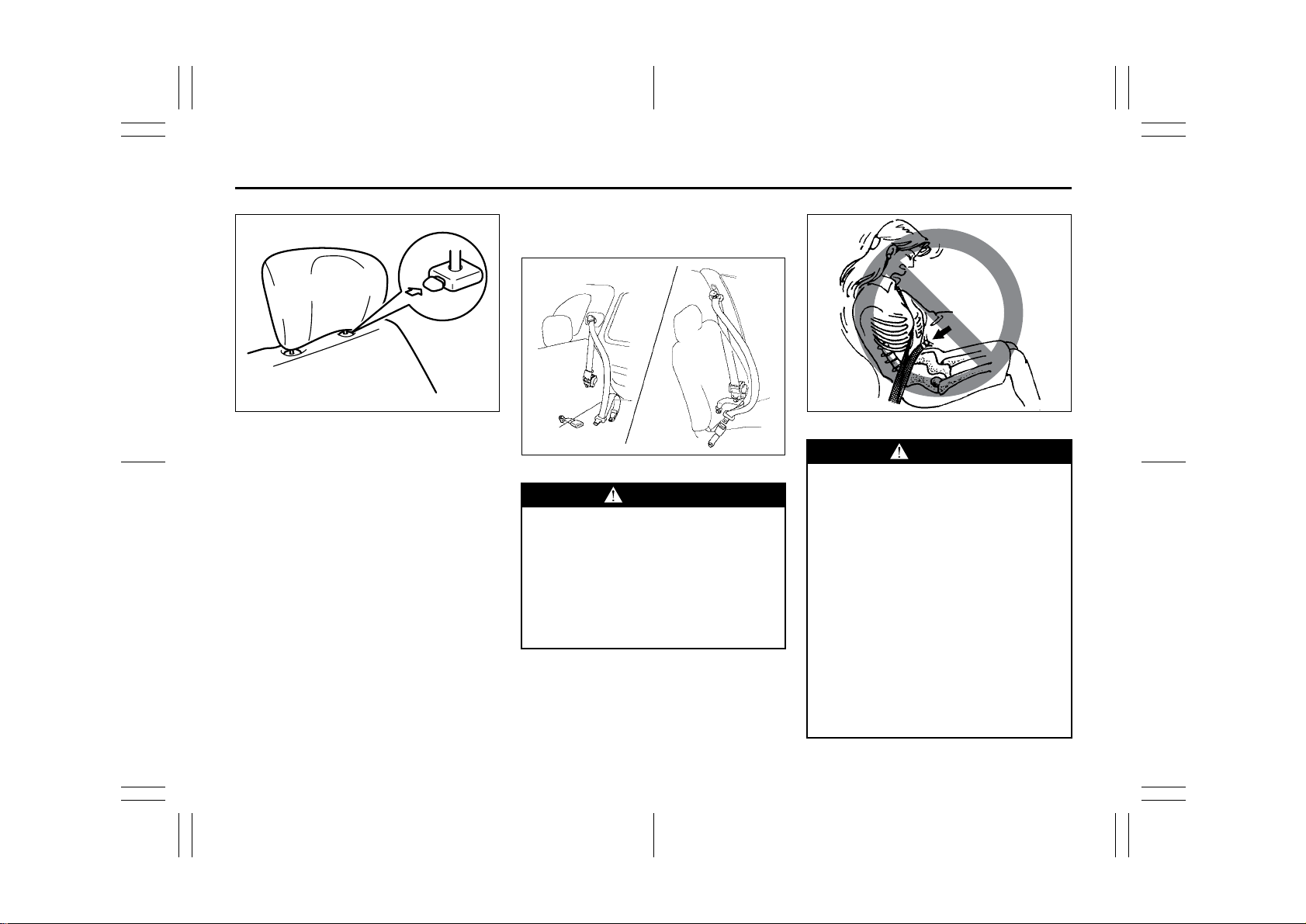
EXAMPLE
54G017
To raise the head restraint, pull upward on
the restraint until it clicks. To lower the
restraint, push down on the restraint while
holding in the release knob. If a head
restraint must be removed (for cleaning,
replacement, etc.), push in the release
knob and pull the head restraint all the way
out.
NOTE:
It may be necessary to recline the seatback to provide enough overhead clearance to remove the head restraint.
Seat Belts and Child Restraint
Systems
EXAMPLE
Rear
An air bag supplements, or adds to,
the frontal crash protection offered
by seat belts. The driver and all passengers must be properly restrained
by wearing seat belts at all times,
whether or not an air bag is mounted
at their seating position, to minimize
the risk of severe injury or death in
the event of a crash.
Front
54G322
WARNING
Above the pelvis
65D606
WARNING
• Never allow persons to ride in the
cargo area of a vehicle. In the event
of an accident, there is a much
greater risk of injury for persons
who are not riding in a seat with
their seat belt securely fastened.
• Seat belts should always be
adjusted as follows:
– the lap portion of the belt should
be worn low across the pelvis,
not across the waist.
– the shoulder straps should be
worn on the outside shoulder
only, and never under the arm.
– the shoulder straps should be
away from your face and neck,
but not falling off your shoulder.
(Continued)
2-13
54G27-03E
Page 27
Head Restraints: 3
Seat Belts and Child Restraint Systems: 3
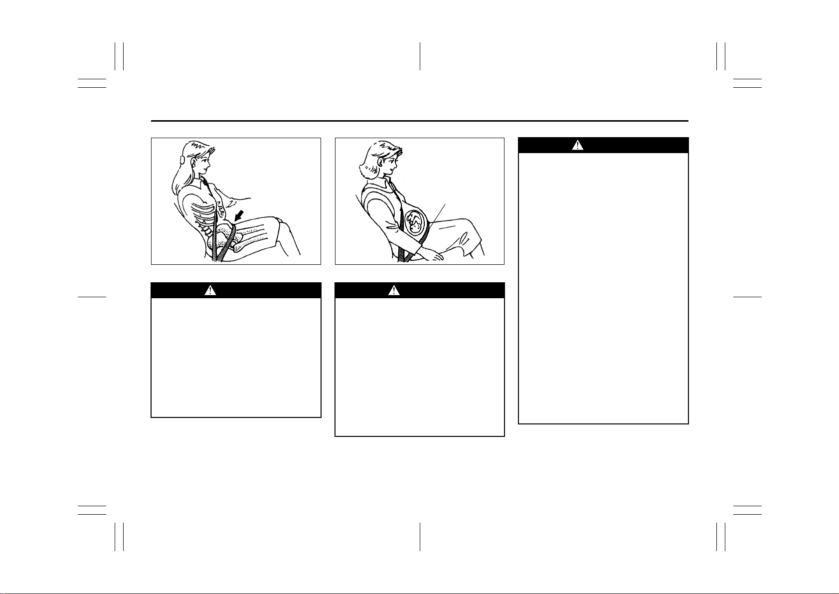
Across the pelvis
65D201 65D199
WARNING
(Continued)
• Shoulder straps should be worn on
the outside shoulder only, and
never under the arm.
• Seat belts should never be worn
with the straps twisted and should
be adjusted as tightly as is comfortable to provide the protection
for which they have been designed.
A slack belt will provide less protection than one which is snug.
(Continued)
as low as possible
across the hips
WARNING
(Continued)
•Pregnant women should use seat
belts, although specific recommendations about driving should be
made by the woman’s medical advisor. Remember that the lap portion
of the belt should be worn as low
as possible across the hips, as
shown in the diagram.
• Make sure that each seat belt
buckle is inserted into the proper
buckle catch. It is possible to cross
the buckles in the rear seat.
(Continued)
BEFORE DRIVING
WARNING
(Continued)
• Do not wear your seat belt over
hard or breakable objects in your
pockets or on your clothing. If an
accident occurs, objects such as
glasses, pens, etc. under the seat
belt can cause injury.
• Never use the same seat belt on
more than one occupant and never
attach a seat belt over an infant or
child being held on an occupant’s
lap. Such seat belt use could cause
serious injury in the event of an
accident.
• Periodically inspect seat belt
assemblies for excessive wear and
damage. Seat belts should be
replaced if webbing becomes
frayed, contaminated, or damaged
in any way. It is essential to replace
the entire seat belt assembly after it
has been worn in a severe impact,
even if damage to the assembly is
not obvious.
• Children age 12 and under sh ould
ride properly restrained in the rear
seat, if equipped.
(Continued)
2-14
54G27-03E
Page 28
Seat Belts and Child Restraint Systems: 3
BEFORE DRIVING
WARNING
(Continued)
• Infants and small children should
never be transported unless they
are properly restrained. Restraint
systems for infants and small children can be purchased commercially and should be used. Make
sure that the system you purchase
meets Federal Motor Vehicle Safety
Standards. Read and follow all the
directions provided by the manufacturer.
• Avoid contamination of seat belt
webbing by polishes, oils, chemicals and particularly battery acid.
Cleaning may safely be carried out
using mild soap and water.
• For children, if the shoulder belt
irritates the neck or face, move the
child closer to the center of the
vehicle.
• All seatbacks should always be in
an upright position when driving,
or seat belt effectiveness may be
reduced. Seat belts are designed to
offer maximum protection when
seatbacks are in the upright position.
Lap-Shoulder Belt
Emergency Locking Retractor (ELR)
The seat belt has an emergency locking
retractor (ELR), which is designed to lock
the seat belt only during a sudden stop or
impact. It also may lock if you pull the belt
across your body very quickly. If this happens, let the belt go back to unlock it, then
pull the belt across your body more slowly.
Automatic Locking Retractor (ALR)
The front passenger’s seat belt and the
rear seat belts have emergency locking
retractors (ELRs) that can be temporarily
converted to function as automatic locking
retractors (ALRs). The ALR mode should
be used if you need to secure a child
restraint system in the seat. Refer to the
“Child Restraint Systems” section for
details.
Safety reminder
Sit up straight and
fully back
Low on hips
60A038
Low on hips
60A040
To reduce the risk of sliding under the belt
during a collision, position the lap portion
of the belt across your lap as low on your
hips as possible and adjust it to a snug fit
2-15
54G27-03E
Page 29
Seat Belts and Child Restraint Systems: 3
BEFORE DRIVING
by pulling the shoulder portion of the belt
upward through the latch plate. The length
of the diagonal shoulder strap adjusts itself
to allow freedom of movement.
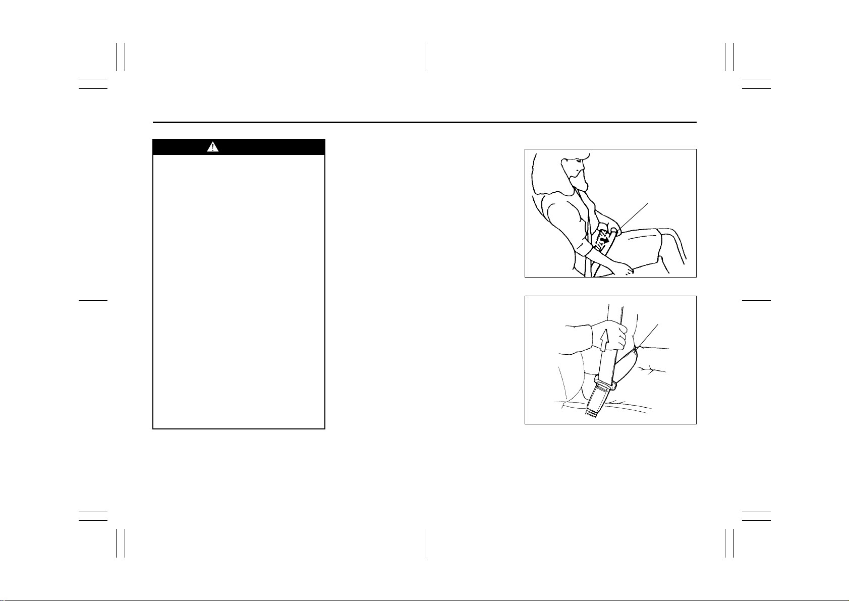
All Seat Belts Except Rear Center
60A036
To fasten the seat belt, sit up straight and
well back in the seat, pull the latch plate
attached to the seat belt across your body
and press it into the buckle until you hear a
“click”.
60A039
To unfasten the belt, push the red
“PRESS” button on the buckle and allow
the belt to retract.
2-16
54G27-03E
Page 30
Seat Belts and Child Restraint Systems: 3
BEFORE DRIVING
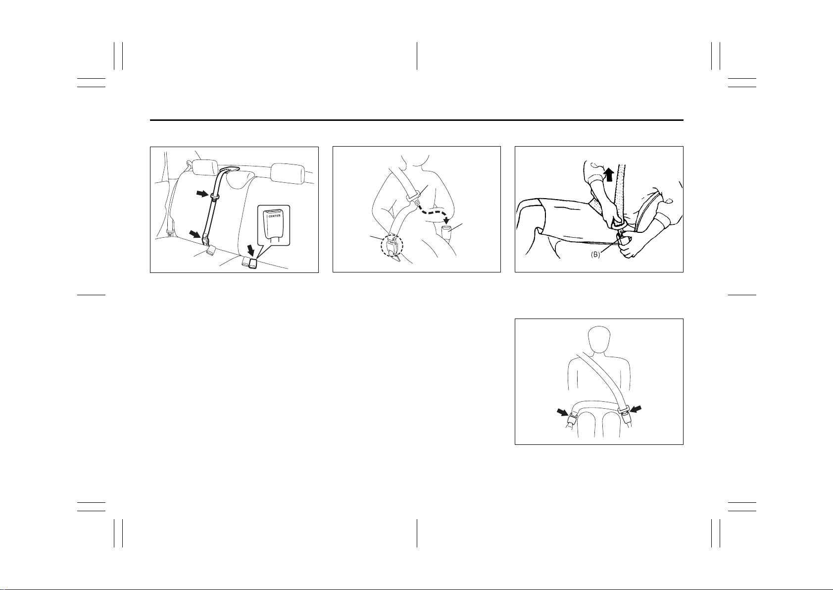
Rear Center Seat Belt
54G356
The rear center seat belt is a “Lap-shoulder belt” with a buckle, a latch plate and a
detachable connector. The buckle is
marked as “CENTER” for distinction from
the rear left seat belt buckle. The rear center seat belt buckle and the connector are
designed so as not to allow a wrong latch
plate to be inserted.
When the rear seatback is in upright position, keep the detachable connector
latched. Only when the rear seatback will
be folded down, unlatch the detachable
connector. To latch and unlatch the connector, see “Unlatching and Latching
Detachable Connector” later in this section.
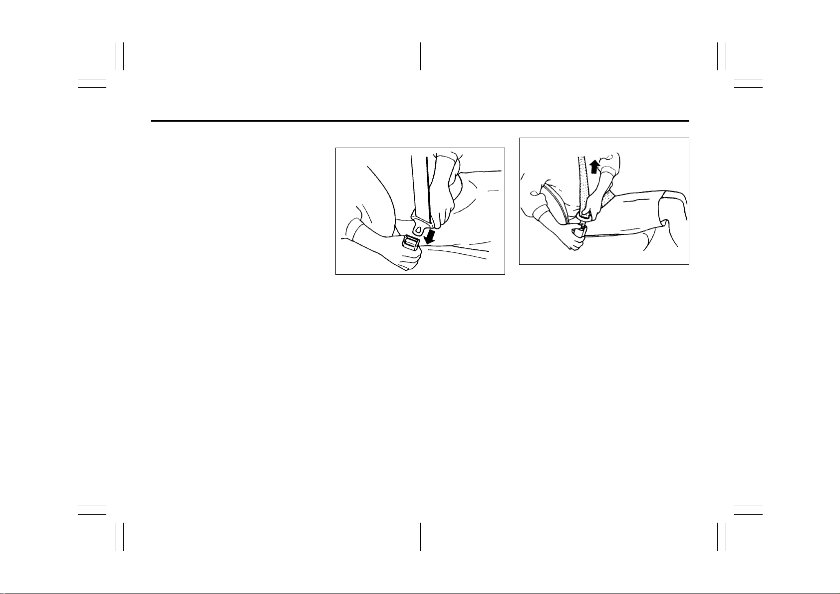
Fastening
(A)
(B)
(1)
54G357
Before fastening the rear center belt, make
sure the detachable connector (1) is
securely latched and the webbing is not
twisted.
To fasten the belt, sit up straight and well
back in the seat, pull the latch plate (A)
across your body and press it into the
buckle (B) until you hear a “click”.
Unfastening
54G358
To unfasten the belt, push the red
“PRESS” button on the buckle (B) and
allow the belt to retract.
54G359
2-17
54G27-03E
Page 31

Seat Belts and Child Restraint Systems: 3
BEFORE DRIVING
54G645
WARNING
To minimize risk of severe injury or
death in the event of a crash, always
wear seat belt with both latches buckled.
Unlatching and Latching
Detachable Connector
Unlatching
(D)
54G365
To unlatch the connector:
1) Insert the ignition key into the slot on
the connector (D) and allow the belt to
retract.
2) Once the belt has completely retracted,
stow the belt in the holder. Refer to
“Stowing Rear Center Lap-Shoulder
Belt” for details later in this section.
CAUTION
When the rear seatback is folded forward, be sure to unlatch the connector of rear center belt. Otherwise, the
seat belt webbing can be damaged.
Latching
To latch the connector:
1) Pull the belt out from the holder.
(C)
(D)
54G367
2) Insert the connector latch plate (C) into
the connector (D) so as to align the triangle marks until you hear a “click”.
WARNING
Make sure the detachable connector
is securely latched and the webbing
is not twisted.
2-18
54G27-03E
Page 32

Seat Belts and Child Restraint Systems: 3
BEFORE DRIVING
Stowing Rear Center Lap-Shoulder
Belt
Be sure to stow the belt after the belt is
retracted completely.
(A)
54G368
To stow the belt, insert the latch plate (A)
into the slot of the holder. To pull the belt
out, simply pull the latch plate.
WARNING
If you park your vehicle outdoors in
direct sunlight or in hot weather, an
exposed latch plate can get hot
enough to burn you. Be careful not to
touch a hot latch plate.
Seat Belt Reminder
Driver’s seat belt reminder light
54G530
Front passenger’s seat belt reminder
light
When the driver and front passenger don’t
buckle their seat belts, the driver’s seat belt
reminder light in the instrument cluster and
the front passenger’s seat belt reminder
light in the information display will come on
and a buzzer will sound as a reminder to
the driver and front passenger to buckle
their seat belts.
WARNING
It is absolutely essential that the
driver and passengers wear their seat
belts at all times. Persons who are
not wearing seat belts have a much
greater risk of injury if an accident
occurs. Make a regular habit of buc kling your seat belt before putting the
key in the ignition.
The seat belt reminder functions as shown
in the figure below. There are some differences between the driver’s seat belt
reminder and the front passenger’s seat
belt reminder. For more details, refer to the
explanation below.
2-19
54G515
54G27-03E
Page 33

Seat Belts and Child Restraint Systems: 3
BEFORE DRIVING
Flow chart
Ignition Switch “ON”
Seat belt is
buckled
Vehicle speed:
below 8 km/h
No reminder
Seat belt is
unbuckled
Vehicle speed:
over 8 km/h
52D219
Vehicle speed:
below 8 km/h
Vehicle speed:
increase to 8 km/h
Seat belt is
unbuckled
Reminder 1
30 sec.
Vehicle speed:
over 8 km/h
Reminder 2
3 min.
Reminder 3
No reminder
Reminder 1 – 3
For each reminder 1 – 3, the reminder light comes on for about 20 seconds, then blinks for
about 55 seconds. When the reminder light first comes on, a buzzer sounds intermittently
for about 6 seconds.
Driver’s seat belt reminder
If the driver’s seat belt remains unbuckled
with the ignition key in the “ON” position,
the driver’s seat belt reminder works as follows:
1) The driver’s seat belt reminder light will
come on for about 20 seconds when
the ignition key is turned to the “ON”
position then will blink for about 55 seconds. When the light comes on, a
buzzer will also sound intermittently for
about 6 seconds (Reminder 1).
2) If the vehicle is driven (vehicle speed >
8 km/h), Reminder 2 will operate about
30 seconds after Reminder 1 has finished.
If the vehicle is not driven (vehicle
speed < 8 km/h), Reminder 2 will operate when driving starts (vehicle speed >
8 km/h).
3) Reminder 3 will operate about 3 minutes after Reminder 2 has finished.
4) Even if the driver’s seat belt remains
unbuckled after Reminder 3, there will
be no further reminders.
If the driver has buckled his or her seat belt
and later unbuckles the seat belt, the
reminder system will be activated from
Reminder 1 or Reminder 2 according to
the vehicle speed. (Refer to the flow chart.)
The driver’s seat belt reminder will be automatically canceled when the driver’s seat
belt is buckled or the ignition switch is
turned off.
2-20
54G27-03E
Page 34

Seat Belts and Child Restraint Systems: 3
BEFORE DRIVING
Front passenger’s seat belt reminder
The front passenger’s seat belt reminder
will activate only when there is a passenger sitting in the front seat. In some situations, however, such as when you place
heavy objects in the front seat, the seat
belt reminder can be activated as if there
were a passenger present. The front passenger’s seat belt reminder works in the
same manner as the driver’s seat belt
reminder, except that it is not activated
until 10 seconds after the ignition switch is
turned to the “ON” position.
Shoulder Anchor Height Adjuster
(if equipped)
EXAMPLE
54G186
Adjust the shoulder anchor height so that
the shoulder belt rides on the center of the
outside shoulder. To adjust the shoulder
anchor height, slide the anchor up or down
while pulling the lock knob out. After
adjustment, make sure that the anchor is
securely locked.
WARNING
Be sure that the shoulder b elt is p ositioned on the center of the outside
shoulder. The belt should be away
from your face and neck, but not falling off your shoulder. Misadjustment
of the belt could reduce the effectiveness of the safety belt in a crash.
Seat Belt Hanger (if equipped)
EXAMPLE
54G045
CAUTION
When you move a seatback, make
sure the belt webbing is hooked in
the seat belt hangers so the seat
belts are not caught by the seatback,
seat hinge, or seat latch. This helps
prevent damage to the belt system.
2-21
54G27-03E
Page 35

Seat Belts and Child Restraint Systems: 3
BEFORE DRIVING
Seat Belt Inspection
EXAMPLE
65D209S
Periodically inspect the seat belts to make
sure they work properly and are not damaged. Check the webbing, buckles, latch
plates, retractors, anchorages and guide
loops. Replace any seat belts which do not
work properly or are damaged.
WARNING
Child Restraint Systems
Be sure to inspect all seat belt
assemblies after any collision. Any
seat belt assembly which was in use
during a collision (other than a very
minor one) should be replaced, even
if damage to the assembly is not
obvious. Any seat belt assembly
which was not in use during a collision should be replaced if it does not
function properly, it is damaged in
any way or the seat belt pretensioners were activated.
60G332
Infant restraint - rear seat only
EXAMPLE
65D202
2-22
54G27-03E
Page 36

Seat Belts and Child Restraint Systems: 3
BEFORE DRIVING
Infant restraint - rear seat only
EXAMPLE
Booster seat
EXAMPLE
65D584
65D203
SUZUKI highly recommends that you use
a child restraint system to restrain infants
and small children. Many different types of
child restraint systems are available; make
sure that the restraint system you select
meets Federal Motor Vehicle Safety Standards.
All child restraint systems are designed to
be secured in vehicle seats by either seat
belts (lap belts or the lap portion of lapshoulder belts) or by special rigid lower
anchor bars built into the seats. Whenever
possible, SUZUKI recommends that child
restraint systems be installed on the rear
seat. According to accident statistics, children are safer when properly restrained in
rear seating positions than in front seating
positions.
If you must use a front-facing child restraint
in the front passenger’s seat, be sure to
move the front passenger’s seat as far
back as possible.
65D607
WARNING
Do not install a rear-facing child
restraint in the front passenger’s
seat. If the passenger’s air bag
inflates, a child in a rear-facing child
restraint could be killed or seriously
injured. The back of a rear-facing
child restraint would be too close to
the inflating air bag.
2-23
54G27-03E
Page 37

Seat Belts and Child Restraint Systems: 3
BEFORE DRIVING
65D608
65D609
WARNING
Children could be endangered in a
crash if their child restraints are not
properly secured in the vehicle.
When installing a child restraint system, be sure to follow the instructions below. Be sure to secure the
child in the restraint system according to the manufacturer’s instructions.
Installation with Lap-Shoulder Seat
Belts (child restraint with no top
strap)
EXAMPLE
83E031
Install your child restraint system according to the instructions provided by the child
restraint system manufacturer. If you install
the child restraint system in the front seat,
be sure to slide the seat to the rearmost
position. After making sure that the seat
belt is securely latched:
2-24
54G27-03E
Page 38

Seat Belts and Child Restraint Systems: 3
BEFORE DRIVING
EXAMPLE EXAMPLE
83E035
1) Pull all of the remaining webbing out of
the retractor. You will hear a click, which
means that the emergency locking
retractor (ELR) has converted to function as an automatic locking retractor
(ALR).
2) Allow the extra webbing to retract, and
pull the webbing toward the retractor to
take up any slack. Make sure that the
lap portion of the belt is tight around the
child restraint system and the shoulder
portion of the belt is positioned so that it
can not interfere with the child’s head or
neck.
83E032
EXAMPLE
83E036
3) Make sure that the retractor has converted to the ALR mode by trying to pull
webbing out of the retractor. If the
retractor is in the ALR mode, the belt
will be locked.
WARNING
If the retractor is not in the ALR
mode, the child restraint system can
move or tip over when your vehicle
turns or stops abruptly.
WARNING
Before installing a child restraint in
the rear center seat, make sure the
detachable connector is securely
latched and the webbing is not
twisted.
2-25
54G27-03E
Page 39

Seat Belts and Child Restraint Systems: 3
BEFORE DRIVING
EXAMPLE
Move to check
65D234
EXAMPLE
Pull to tighten
65D235
4) Try moving the child restraint system in
all directions, to make sure it is securely
installed. If you need to tighten the belt,
pull more webbing toward the retractor.
To revert from ALR to ELR
EXAMPLE
65D267
When you unbuckle the seat belt and allow
it to retract to a certain length, the retractor
will automatically revert back to the normal
ELR mode.
Installation with the LATCH System
Rigid lower connecting
bar type
Your vehicle is equipped with lower
anchors for securing up to two standard
LATCH-type child restraints in the second
row seats. (LATCH stands for Lower
Flexible lower connecting
strap type
65D337
54G336
2-26
54G27-03E
Page 40

Seat Belts and Child Restraint Systems: 3
BEFORE DRIVING
Anchors and Tethers for Children.) The
anchors are located where the rear of the
seat cushion meets the bottom of the seatback. Their position is identified by a small
round label affixed to the seatback as
shown in the illustration.
Install a LATCH-type child restraint system
according to the instructions provided by
the child restraint system manufacturer.
After installing the child restraint system,
try moving it in all directions, especially forward, to make sure the flexible straps or
rigid connecting bars are securely latched
to the anchors.
NOTE:
Although there are three second row seating positions, you cannot install three
LATCH type child restraints in the second
row seats. You can install one or two
LATCH restraint(s). Be sure to install the
LATCH type child restraint(s) in the outboard seating positions.
If your LATCH restraint has flexible lower
connecting straps, these general instructions apply:
1) If possible, fold the seatback rearward
for easier installation.
EXAMPLE
65D339
2) Place the child restraint in the second
row seat, feeding the strap hooks
through the slots in the seat cushion or
the slots in the seatback bottom.
EXAMPLE
65D340
3) Snap the strap hooks to the anchors.
Take care not to pinch your fingers.
EXAMPLE
2-27
65D341
4) Return the seatback to the normal,
upright position. Tighten the lower
straps as described in the child restraint
54G27-03E
Page 41

Seat Belts and Child Restraint Systems: 3
BEFORE DRIVING
owner’s manual. Attach the top tether
strap, if applicable.
EXAMPLE
65D342
5) Make sure the child restraint is securely
fastened by trying to move the child
restraint system in all directions, especially forward.
WARNING
The seatback should always be
securely latched in a fairly upright
position when any type of child seat
is installed. An unlatched or reclined
seatback will reduce the intended
effectiveness of the child restraint
system.
If your LATCH restraint has rigid lower connecting bars, these general instructions
apply:
1) If possible, fold the seatback rearward
for easier installation.
EXAMPLE
54G182
2) Place the child restraint in the second
row seat, inserting the connecting bars
through the slots in the seat cushion or
the slots in the seatback bottom.
EXAMPLE
54G183
3) Use your hands to carefully align the
connecting bar tips with the anchors.
Take care not to pinch your fingers.
EXAMPLE
54G184
4) Push the child restraint toward the
anchors so that the connecting bar tips
2-28
54G27-03E
Page 42

Seat Belts and Child Restraint Systems: 3
BEFORE DRIVING
are partially hooked to the anchors.
Use your hands to confirm the position.
EXAMPLE
54G185
5) Grasp the front of the child restraint an d
push the child restraint forcefully to
latch the connecting bars. Make sure
they are securely latched by trying to
move the child restraint system in all
directions, especially forward.
6) Return the seatback if folded. Attach
the top tether strap, if applicable.
WARNING
The seatback should always be
securely latched in a fairly upright
position when any type of child seat
is installed. An unlatched or reclined
seatback will reduce the intended
effectiveness of the child restraint
system.
Installation-Child Restraint with Top
Strap
EXAMPLE
54G296
Some child restraint systems require the
use of a top strap. Top strap anchor brackets are provided in your vehicle at the locations shown in the illustrations. Install the
child restraint system as follows:
1) Secure the child restraint on the rear
seat using the procedure described
above for securing a restraint system
that does not require a top strap.
2) Hook the top strap to the anchor
bracket and tighten the top strap
according to the instructions provided
by the child restraint system manufacturer. Be sure to attach the top strap to
the corresponding anchor located
directly behind the child restraint.
EXAMPLE
54G337
3) When routing the top strap, be sure to
pass it between the head restraint and
the rear seatback as shown. (Refer to
“Head Restraints” section for details on
how to raise or lower the head
restraint.)
4) Make sure that cargo does not interfere
with routing of the top strap.
2-29
54G27-03E
Page 43

Seat Belts and Child Restraint Systems: 3
BEFORE DRIVING
Seat Belt Extender
65D613
(1) Center of body
(2) Less than 152 mm (6 inches)
(3) Open end of extender buckle
If a seat belt cannot be fastened securely
because it is not long enough, see your
authorized SUZUKI dealer for a seat belt
extender. Seat belt extenders are available
for each seating position except for the
rear center position. After inspecting the
relationship between the seat belt length,
the occupant’s body size, and the seat
adjustment (the driver’s seat should alwa ys
be adjusted as far back as possible while
still maintaining control of the vehicle, and
other adjustable seats should be adjusted
as far back as possible), your dealer can
select the appropriate seat belt extender.
• A seat belt extender should only be used
for the person, vehicle and seating location it was provided for.
• When using the extender, ensure that
both ends are latched securely. Do not
use the extender if the open end of the
extender’s buckle is within 152 mm (6
inches) of the center of the occupant’s
body (See diagram). Use of the extender
when the buckle is too close to the center of the body could increase the risk of
abdominal injury in the event of an accident, and could cause the shoulder belt
to be positioned incorrectly.
• Make sure to use the correct buckle corresponding to your seating position.
• Seat belt extenders are not intended for
use by pregnant women, and should
only be used upon approval by their
medical advisors.
• Remove and stow the extender when it
is not being used.
WARNING
Failure to follow these instructions
may increase the risk of injury in a
crash.
• Only use an extender for the person, vehicle and seating position it
was provided for.
• Do not use if open end of
extender’s buckle is within 152 mm
(6 inches) of center of occupant’s
body (See diagram).
• Remove and stow the extender
when it is not being used.
WARNING
If you are using a seat belt extender
in the front passenger’s seat, it is
important to sit in the seat before
inserting the latch plate of the seat
belt extender into the vehicle seat
belt buckle. If the front passenger
sensing system does not sense your
weight on the front seat when the
latch plate of the seat belt extender is
inserted into the vehicle seat belt
buckle, the front passenger’s air bag
will be turned off and will remain off,
and the “PASS AIRBAG OFF” indicator will be illuminated.
(Continued)
2-30
54G27-03E
Page 44

Seat Belts and Child Restraint Systems: 3
BEFORE DRIVING
WARNING
(Continued)
To avoid turning off the front passenger’s air bag when using a seat belt
extender in the front passenger’s
seat, be sure to follow these instructions.
• First insert the latch plate of the
vehicle seat belt into the buckle of
the seat belt extender.
• While you are sitting in the seat,
insert the latch plate of the seat
belt extender into the vehicle seat
belt buckle.
• Confirm that the “PASS AIRBAG
OFF” indicator is not illuminated
when you are sitting in the seat
with the seat belt buckled.
• When unfastening the seat belt,
unlatch the latch plate of the seat
belt extender from the vehicle seat
belt buckle first.
• When not using the seat belt
extender, remove and stow it.
Seat Belt Pretensioner System
EXAMPLE
52D011
WARNING
This section of the owner’s manual
describes your SUZUKI’s SEAT BELT
PRETENSIONER SYSTEM. Please
read and follow ALL these instructions carefully to minimize your risk
of severe injury or death.
Your vehicle is equipped with a seat belt
pretensioner system at the front seating
positions. You can use the pretensioner
seat belts in the same manner as ordinary
seat belts.
The seat belt pretensioner system is activated based on crash severity. This system
does not work when the seat belt is
unbuckled. The crash sensors and the
electronic controller of the air bag system
also control the seat belt pretensioners.
For precautions and general information
including servicing the pretensioner system, refer to the “Supplemental Restraint
System (air bags)” section in addition to
this “Seat Belt Pretensioner System” section, and follow all those precautions.
The pretensioner is located in each front
seat belt retractor. The pretensioner tightens the seat belt so the belt fits the occupant’s body more snugly in the event of a
frontal crash. The retractors will remain
locked after the pretensioners are activated. Upon activation, some noise will
occur and some smoke may be released.
These conditions are not harmful and do
not indicate a fire in the vehicle.
The driver and all passengers must be
properly restrained by wearing seat belts
at all times, whether or not a pretensioner
is equipped at their seating position, to
minimize the risk of severe injury or death
in the event of a crash. Sit fully back in the
seat; sit up straight; do not lean forward or
sideways. Adjust the belt so the lap portion
of the belt is worn low across the pelvis,
not across the waist. Please refer to the
“Seat Adjustment” section and the instructions and precautions about the seat belts
in this “Seat Belts and Child Restraint Systems” section for details on proper seat
and seat belt adjustments.
Please note that the pretensioners will activate only in severe frontal collisions. They
2-31
54G27-03E
Page 45

Seat Belts and Child Restraint Systems: 3
BEFORE DRIVING
are not designed to activate in rear
impacts, side impacts, rollovers or minor
frontal collisions. The pretensioners can be
activated only once. If the pretensioners
are activated, have the pretensioner system serviced by an authorized SUZUKI
dealer as soon as possible.
If the “AIR BAG” light on the instrument
cluster does not blink or come on briefly
when the ignition switch is turned to the
“ON” position, stays on for more than 10
seconds, or comes on while driving, the
pretensioner system or the air bag system
may not work properly. Have both systems
inspected by an authorized SUZUKI dealer
as soon as possible.
Service on or around the pretensioner system components or wiring must be performed only by an authorized SUZUKI
dealer who is specially trained. Improper
service could result in unintended activation of pretensioners or could render the
pretensioner inoperative. Either of these
two conditions may result in personal
injury.
To prevent damage or unintended activation of the pretensioners, be sure the battery is disconnected and the ignition switch
has been in the “LOCK” position for at least
90 seconds before performing any electrical service work on your SUZUKI. Do not
touch pretensioner system components or
wiring. The wires are wrapped with yell ow
tape or yellow tubing, and the couplers are
yellow. When scrapping your SUZUKI, ask
your SUZUKI dealer, body repair shop or
scrap yard for assistance.
Supplemental Restraint
System (air bags)
EXAMPLE
54G022
WARNING
This section of the owner’s manual
describes the protection provided by
your vehicle’s SUPPLEMENTAL
RESTRAINT SYSTEM (air bags).
Please read and follow ALL these
instructions carefully to minimize
your risk of severe injury or death in
the event of a collision.
Your vehicle has advanced front air bags
and side air bags for the driver and right
front passenger.
2-32
54G27-03E
Page 46

Seat Belts and Child Restraint Systems: 3
BEFORE DRIVING
10
9
1
6
Your vehicle is equipped with a Supplemental Restraint System consisting of the
following components in addition to a lapshoulder belt at each front seating position.
2
1. Driver’s air bag
2. Front passenger’s air bag
3
3. Side air bags
4. Seat belt pretensioners
7
5. Air bag controller
6. Driver’s seat position sensor
7. Front passenger’s weight sensors
8. Occupant classification module
9. “PASS AIRBAG OFF” indicator
10.Forward crash sensor
11.Side crash sensor
12.Seat belt buckle sensor
2-33
8
4
11
7
center pad of the steering wheel. The
words “SRS AIRBAG” are molded into the
air bag cover to identify the location of the
air bag. The front passenger’s air bag is
located behind the passenger’s side of the
The driver’s air bag is located behind the
5
11
3
4
12
54G516
dashboard. The words “SRS AIRBAG” are
molded into the air bag cover to identify the
location of the air bag.
54G27-03E
Page 47

Seat Belts and Child Restraint Systems: 3
BEFORE DRIVING
54G442
Side air bags are located in the part of the
front seatbacks closest to the doors. The
words “SRS AIRBAG” are molded into the
side air bag cover to identify the location of
the side air bags.
Frontal collision range
Side collision range
60G032
54G026
Front air bags will not inflate
65D236
Front air bags will probably not inflate
65D237
2-34
54G27-03E
Page 48

Seat Belts and Child Restraint Systems: 3
BEFORE DRIVING
Side air bag will not inflate
Side air bag will probably not inflate
54G027
54G028
Front air bags are designed to inflate only
in severe frontal collisions. They are not
designed to inflate in rear impacts, side
impacts, rollovers or minor frontal collisions, since they would offer no protection
in those types of accidents. Side air bags
are designed to inflate only in severe sideimpact collisions. They are not designed to
inflate in frontal or rear collisions, rollovers
or minor side collisions, since they would
offer no protection in those types of accidents. Only the side air bag on the side of
the vehicle that is struck will inflate.
Remember, since air bags deploy only one
time during an accident, seat belts are
needed to restrain occupants from further
movements during the accident.
Therefore, an air bag is NOT a substitute
for seat belts. To maximize your protection,
ALWAYS WEAR YOUR SEAT BELTS. Be
aware that no system can prevent all possible injuries that may occur in an accident.
WARNING
Air bags supplement, or add to, the
crash protection offered by seat
belts. The driver and all passengers
must be properly restrained by wearing seat belts at all times, whether or
not air bags are mounted at their
seating position, to minimize the risk
of severe injury or death in the event
of a crash.
60G300
If the “AIR BAG” light on the instrument
cluster does not blink when the ignition
switch is first turned to the “ON” position,
or the “AIR BAG” light stays on, or comes
on while driving, the air bag system may
not work properly. Have the air bag system
inspected by an authorized SUZUKI dealer
as soon as possible.
2-35
54G27-03E
Page 49

Seat Belts and Child Restraint Systems: 3
Supplemental Restraint System (advanced air bags):
3, 9, 12
BEFORE DRIVING
Your vehicle has “dual stage” front air
bags, which adjust the air bag inflation
force according to crash severity, driver’s
seat fore/aft position and whether or not
the driver’s seat belt is fastened. Also, your
vehicle has a front passenger sensing system, which turns off the front passenger’s
front air bag under certain conditions.
Driver’s Seat Position Sensor
The driver’s seat is equipped with a seat
position sensor to monitor the driver seat
fore/aft position. The seat position sensor
provides information which is used to
judge if the driver’s front air bag should
deploy at reduced power or at full power.
CAUTION
Do not put any cargo or metal objects
under the seat. The seat position sensor may not work properly or may be
damaged if it is covered with something.
When the seat position sensor has a problem, the “AIR BAG” light on the instrument
cluster will turn on. If this happens, deployment of the driver’s front air bag will not
include consideration of seat fore/aft position. Have the air bag system inspected by
an authorized SUZUKI dealer as soon as
possible.
Driver’s Seat Belt Buckle Sensor
The driver’s seat belt buckle is equipped
with a sensor to monitor whether or not the
driver’s seat belt is fastened. The driver’s
seat belt buckle sensor provides information which is used to judge if the driver’s
front air bag should deploy at reduced
power or at full power.
When the buckle sensor has a problem,
the “AIR BAG” light on the instrument cluster will turn on. If this happens, deployment
of the driver’s front air bag will not include
consideration of whether the driver’s seat
belt is fastened or not. Have the air bag
system inspected by an authorized
SUZUKI dealer as soon as possible.
Front Passenger Sensing System
The front passenger sensing system will
turn off the front passenger’s front air bag
under certain conditions. This system
works using weight sensors that are part of
the front passenger’s seat and a seat belt
sensor. The front passenger sensing system is designed to detect whether an occupant is present in the seat and, if an
occupant is present, to determine whether
the front passenger’s front air bag should
be enabled or disabled (turned off).
NOTE:
The front passenger’s side air bag is not
controlled by the front passenger sensing
system.
54G517
When the ignition switch is turned to the
“ON” position, the “PASS AIRBAG OFF”
indicator comes on for several seconds to
let you know the system is working. When
the front passenger sensing system has
turned off the front passenger’s front air
bag, the “PASS AIRBAG OFF” indicator
will come on and stay on to remind you
that the front passenger’s front air bag is
off.
The front passenger sensing system is
designed to turn off the front passenger’s
front air bag when the weight on the front
seat is 30 kg (65 lbs) or less. The front air
bag should be turned off in the following
situations:
• There is no occupant in the front passenger seat.
• The occupant of the front passenger
seat leaves the seat for a period of time.
2-36
54G27-03E
Page 50

Supplemental Restraint System (advanced air bags):
3, 9, 12
BEFORE DRIVING
• The occupant of the front passenger
seat is an infant or small child in a child
restraint system or a small child in a
booster seat.
• A smaller person, such as a child who
has outgrown child restraints or a very
small adolescent is seated in the front
passenger seat.
NOTE:
If the front passenger seat is unoccupied,
the “PASS AIRBAG OFF” indicator will not
come on but the front passenger’s front air
bag will not deploy.
If you have secured a child in the front passenger seat in a forward-facing child
restraint system or booster seat and the
“PASS AIRBAG OFF” indicator light is not
on, turn the vehicle off, remove the child
restraint or booster seat from the vehicle
and reinstall it following the child restraint
or booster seat manufacturer’s directions.
Refer to “Seat Belts and Child Restraint
Systems” in this section. If you have reinstalled the child restraint or booster seat
and restarted the vehicle, and the “PASS
AIRBAG OFF” indicator is still not on,
secure the child in the child restraint or
booster seat in a rear seat position in the
vehicle and check with your dealer.
65D607
WARNING
Do not install a rear-facing child
restraint in the front passenger’s
seat. If the passenger’s air bag
inflates, a child in a rear-facing child
restraint could be seriously injured.
The back of a rear-facing child
restraint would be too close to the
inflating air bag.
According to accident statistics, children
are safer when properly restrained in rear
seating positions than in front seating positions. Whenever possible, SUZUKI recommends you install child restraints in the
rear seat.
The front passenger sensing system is
designed to enable the front passenger’s
front air bag when the system senses a
properly-seated adult in the front passenger’s seat. When the passenger sensing
system has allowed the front air bag to be
enabled, the “PASS AIRBAG OFF” indicator will remain off to remind you that the air
bag is active.
If a person of adult size is sitting in the
front passenger’s seat and the “PASS AIRBAG OFF” indicator comes on, it could be
because that person isn’t sitting properly in
the seat. If this happens, unfasten the seat
belt, sit upright in the center of the seat
with the seatback nearly vertical and your
legs outstretched, and refasten the seat
belt.
2-37
54G27-03E
Page 51

Supplemental Restraint System (advanced air bags):
3, 9, 12
BEFORE DRIVING
52D258
When seated as shown in the above illustration, the front passenger sensing system senses a properly-seated occupant
and enables the air bag.
When using a seat belt extender, follow the
instructions in the “Seat Belt Extender”
section.
WARNING
The front passenger sensing system
may not work properly in the following situations:
• The occupant is not wearing the
seat belt properly.
• The occupant is sitting near the
dashboard or is not sitting in the
proper position.
• A rear seat occupant is pushing or
pulling on the seatback or is pushing up the seat cushion using their
feet.
• Objects placed under the seat are
pushing up on the seat cushion.
• Heavy objects are hanging on the
seatback.
WARNING
If the “AIR BAG” light in the instrument cluster ever comes on and
stays on, it means that something
may be wrong with the air bag system. If this ever happens, have the
vehicle inspected by an authorized
SUZUKI dealer immediately, because
the air bags may not offer the protection for which they were designed.
WARNING
If the “PASS AIRBAG OFF” indicator
on the information display turns on
even though there is no occupant or
an adult occupant in the front passenger’s seat, it means that something may be wrong with the
passenger sensing system. Have the
system inspected by an authorized
SUZUKI dealer as soon as possible.
WARNING
• Do not spill any liquids on the seat.
Liquids can damage the sensors
under the front seat.
• Have the driver’s seat position sensor and the front passenger’s seat
weight sensors inspected by an
authorized SUZUKI dealer after a
collision.
• Do not replace the front seats. If
you replace them, the air bags and
front passenger sensing system
may not work properly.
• Do not use a seat cover. If you use
a seat cover, the front passenger
sensing system may not work properly.
2-38
54G27-03E
Page 52

Supplemental Restraint System (advanced air bags):
3, 9, 12
BEFORE DRIVING
How the System Works
In a frontal collision, the crash sensors will
detect rapid deceleration and send a signal
to the controller. If the controller judges
that the deceleration represents a severe
frontal crash, the controller will trigger the
inflators. The controller also judges:
• Whether the air bags should deploy at
reduced power or at full power according
to crash severity, driver’s seat fore/aft
position and whether or not the driver’s
seat belt is fastened.
• Whether the front passenger’s front air
bag should deploy or not based on classification of the occupant of the front
passenger’s seat.
Since your vehicle is equipped with side air
bags, crash sensors will detect a side collision, and if the controller judges that the
side collision is severe enough, it will trigger a side inflator.
The inflators inflate the appropriate air
bags with nitrogen or argon gas. The
inflated air bags provide a cushion for your
head (front air bags only) and upper body.
The air bag inflates and deflates so quickly
that you may not even realize that it has
activated. The air bag will neither hinder
your view nor make it harder to exit the
vehicle.
Air bags must inflate quickly and forcefully
in order to reduce the chance of serious or
fatal injuries. However, an unavoidable
consequence of the quick inflation is that
the air bag may irritate bare skin, such as
the facial area against a front air bag. Also,
upon inflation, a loud noise will occur and
some powder and smoke will be released.
These conditions are not harmful and do
not indicate a fire in the car. Be aware,
however, that some air bag components
may be hot for a while after inflation.
A seat belt helps keep you in the proper
position for maximum protection when an
air bag inflates. Adjust your seat as far
back as possible while still maintaining
control of the vehicle. Sit fully back in your
seat; sit up straight; do not lean over the
steering wheel or dashboard. Front occupants should not lean on or sleep against
the door. Please refer to the “Seat Adjustment” section and the “Seat Belts and
Child Restraint Systems” section in the
“BEFORE DRIVING” section for details on
proper seat and seat belt adjustments.
54G582
WARNING
• The driver should not lean over the
steering wheel. The front passenger should not rest his or her bod y
against the dashboard, or otherwise get too close to the dashboard. Front occupants should not
lean on or sleep against the door. In
these situations, the out-of-position occupant would be too close to
an inflating air bag, and may suffer
severe injury.
(Continued)
2-39
54G27-03E
Page 53

Supplemental Restraint System (advanced air bags):
3, 9, 12
BEFORE DRIVING
WARNING
(Continued)
• Do not attach any objects to, or
place any objects over, the steering
wheel or dashboard. Do not place
any objects between the air bag
and the driver or front passenger.
These objects may interfere with air
bag operation or may be propelled
by the air bag in the event of a
crash. Either of these conditions
may cause severe injury.
• Do not place seat covers on the
front seats, because seat covers
could restrict the side air bag’s
inflation. Also, do not place any
cup holders on the door, as th e cu p
holder could be propelled by the air
bag in the event of a crash. Either
of these conditions may cause
severe injury.
Note that even though your vehicle may be
moderately damaged in a collision, the collision may not have been severe enough to
trigger the front or side air bags to inflate. If
your car sustains ANY front-end or side
damage, have the air bag system
inspected by an authorized SUZUKI dealer
to ensure it is in proper working order.
Your vehicle is equipped with a diagnostic
module which records information about
the air bag system if the air bags deploy in
a crash. The module records information
about overall system status, which sensors
activated the deployment, and whether the
front seat belts were in use.
Servicing the Air Bag System
If the air bags inflate, have the air bags and
related components replaced by an authorized SUZUKI dealer as soon as possible.
If your vehicle ever gets in deep water and
the driver’s floor is submerged, the air bag
controller could be damaged. If this happens, have the air bag system inspected
by an authorized SUZUKI dealer as soon
as possible.
Special procedures are required for servicing or replacing an air bag. For that reason,
only an authorized SUZUKI dealer should
be allowed to service or replace your air
bags. Please remind anyone who services
your vehicle that it has air bags.
Service on or around air bag components
or wiring must be performed only by an
authorized SUZUKI dealer. Improper service could result in unintended air bag
deployment or could render the air bags
inoperative. Either of these two conditions
may result in severe injury.
To prevent damage or unintended inflation
of the air bag system, be sure the battery
is disconnected and the ignition switch has
been in the “LOCK” position for at least 90
seconds before performing any electrical
service work on your vehicle. Do not touch
air bag system components or wires. The
wires are wrapped with yellow tape or yellow tubing, and the couplers are yellow for
easy identification.
Scrapping a car that has an undeployed air
bag can be hazardous. Ask your dealer,
body repair shop or scrap yard for help
with disposal.
If it is necessary to modify the advanced
front air bag system to accommodate a
person with disabilities, owners in the continental United States can call American
Suzuki toll-free at 1-800-934-0934, or write
to:
American Suzuki Motor Corporation
Automotive Customer Relations
3251 East Imperial Highway
Brea, CA 92821-6795
If you purchased your SUZUKI in Canada
please contact the Suzuki Canada Customer Relations Department by telephone
at 1-905-889-2677 extension 2254 or in
writing at:
Suzuki Canada Inc.
Customer Relations
100 East Beaver Creek Road
Richmond Hill, On
L4B 1J6
2-40
54G27-03E
Page 54

Supplemental Restraint System (advanced air bags):
3, 9, 12
BEFORE DRIVING
MEMO
2-41
54G27-03E
Page 55

60G405
STEERING COLUMN CONTROLS
STEERING COLUMN CONTROLS
Ignition Switch ................................................................ ... ..3-1
Lighting/Turn Signal Control Lever ...................................3-3
Windshield Wiper and Washer Lever ................................ 3-4
Rear Window Wiper/Washer Switch (if equipped) ........... 3-5
Tilt Steering Lock Lever ..................................... ... .. ........... 3-6
Cruise Control (if equipped) ...............................................3-6
Remote Audio Controls (if equipped) ...............................3-8
Horn ......................................................................................3-8
3
54G27-03E
Page 56

Ignition Switch: 8
STEERING COLUMN CONTRO LS
65D611
WARNING
To avoid possible injury, do not operate controls by reaching through the
steering wheel.
Ignition Switch
60B041
The ignition switch has the following four
positions:
LOCK
This is the normal parking position. It is the
only position in which the key can be
removed.
Manual transaxle
Push
Turn to “LOCK”
60A055
• Manual transaxle vehicles
You must push in the key to turn it to the
“LOCK” position. It locks the ignition, and
prevents normal use of the steering
wheel after the key is removed.
• Automatic transaxle vehicles
The gearshift lever must be in the “P”
(Park) position to turn the key to the
“LOCK” position. It locks the ignition and
prevents normal use of the steering
wheel and gearshift lever.
3-1
54G27-03E
Page 57

Ignition Switch: 8
Automatic transaxle
(1)
• If the gearshift lever can not be shifted
out of “P” (Park) in the normal way,
remove the cover (1) over the button,
and pushing the release button with the
key in the “ON” or “ACC” position will
permit movement of the gearshift lever
out of “P” (see “If You Can Not Shift
Automatic Transaxle Gearshift Lever Out
of “P” (PARK)” in the INDEX). The gearshift lever can be moved back to “P”
without pushing the release button.
To release the steering lock, insert the key
and turn the ignition switch clockwise to
one of the other positions. If you have trouble turning the key to unlock the steering,
try turning the steering wheel slightly to the
right or left while turning the key.
54G513
60A300S
ACC
Accessories such as the radio can operate, but the engine is off.
ON
This is the normal operating position. All
electrical systems are on.
START
This is the position for starting the engine
using the starter motor. The key should be
released from this position as soon as the
engine starts.
STEERING COLUMN CONTROLS
WARNING
• For manual transaxle vehicles,
never remove the ignition key while
the vehicle is moving. The steering
wheel will lock and you will not be
able to steer the vehicle.
• A lways carry the ignition key when
leaving the vehicle even if for a
short time. Also do not leave children or pets alone in a parked vehicle. Unattended children could
cause accidental movement of the
vehicle or could tamper with power
windows. Children or pets could
also suffer from heats trok e in wa rm
or hot weather, which could result
in severe injury or even death.
CAUTION
• Do not turn the starter motor for
more than 15 seconds at a time. If
the engine does not start, wait 15
seconds before trying again. If the
engine does not start after several
attempts, check the fuel and ignition systems or consult your
SUZUKI dealer.
• D o not leave the ignition switch in
the “ON” position if the engine is
not running or the battery will discharge.
3-2
54G27-03E
Page 58

Lighting/Turn Signal Control Lever: 8
STEERING COLUMN CONTRO LS
Lighting/Turn Signal Control
Lever
This control lever is located on the outboard side of the steering column. Operate
the lever as described below.
Lighting Operation
54G030
To turn the lights on or off, twist the knob
on the end of the lever. There are three
positions: in the “OFF” position all lights
are off; in the middle position the front
parking lights, tail-lights, license plate light
and instrument lights are on, but the headlights are off; in the third position the headlights come on in addition to the other
lights.
HIGH
LOW
PASS
54G031
With the headlights on, push the lever forward to switch to the high beams or pull
the lever toward you to switch to the low
beams. When the high beams are on, a
light on the instrument panel will come on.
To momentarily activate the high beams as
a passing signal, pull the lever slightly
toward you and release it when you have
completed the signal.
Daytime Running Light (D.R.L.) System
The headlights light, but are dimmer than
the low beam, when the following three
conditions are all met. Also, the D.R.L. indicator light on the instrument panel comes
on.
Conditions for D.R.L. system operation:
1) The engine is running.
2) The parking brake is released.
3) The lighting switch is at either the “OFF”
or the “Middle” position.
NOTE:
Be sure to turn the lighting switch to the
third position at night or at any time of the
day when driving or weather conditions
require the headlights to operate at full
brightness and the taillights to be on.
Lights “On” reminder
A buzzer sounds to remind you to turn off
the lights if they are left on when the ignition key is removed and the driver’s door is
opened.
3-3
54G27-03E
Page 59

Lighting/Turn Signal Control Lever: 8
Windshield Wiper and Washer Lever: 8
STEERING COLUMN CONTROLS
Turn Signal Operation
With the ignition switch in the “ON” position, move the lever up or down to activate
the right or left turn signals.
54G032
Normal turn signal
Move the lever all the way up to signal a
right turn or all the way down to signal a
left turn. When the turn is completed, the
signal will cancel and the lever will return to
its normal position.
Lane change signal
In some turns, such as changing lanes, the
steering wheel is not turned far enough to
cancel the turn signal. For convenience,
you can flash the turn signal by moving the
lever part way and holding it there. The
lever will return to its normal position when
you release it.
Windshield Wiper and Washer
Lever
Windshield Wipers
EXAMPLE
OFF
INT
LO
HI
52D170
To turn the windshield wipers on, move the
lever down to one of the three operating
positions. In the “INT” position (if
equipped), the wipers operate intermittently. The “INT” position is very convenient
for driving in mist or light rain. In the “LO”
position, the wipers operate at a steady
low speed. In the “HI” position, the wipers
operate at a steady high speed. To turn off
the wipers, move the lever back to the
“OFF” position.
EXAMPLE
54G479
If the lever is equipped with the “INT TIME”
control, turn the control forward or rearward to adjust the intermittent wiper operation to the desired interval.
3-4
54G27-03E
Page 60

Windshield Wiper and Washer Lever: 8
Rear Window Wiper/Washer Switch: 8
STEERING COLUMN CONTRO LS
Windshield Washer
EXAMPLE
52D172
To spray windshield washer fluid, pull the
lever toward you. The windshield wipers
will automatically turn on at low speed if
they are not already on and if the “INT”
position is equipped.
WARNING
• To prevent windshield icing in cold
weather, turn on the defroster to
heat the windshield before and during windshield washer use.
• Do not use radiator antifreeze in
the windshield washer reservoir. It
can severely impair visibility when
sprayed on the windshield, and can
also damage your vehicle’s paint.
CAUTION
To help prevent damage to windshield wiper and washer system
components, you should take the following precautions:
• Do not continue to hold in the lever
when there is no windshield
washer fluid being sprayed or the
washer motor can be damaged.
• D o not attempt to remove dirt from
a dry windshield with the wipers o r
you can damage the windshield
and the wiper blades. Always wet
the windshield with washer fluid
before operating the wipers.
• C lear ice or packed snow from the
wiper blades before using the wipers.
• Check the washer fluid level r egularly. Check it often when the
weather is bad.
• O nly fill the washer fluid reservoir
3/4 full during cold weather to allow
room for expansion if the temperature falls low enough to freeze the
solution.
Rear Window Wiper/Washer
Switch (if equipped)
EXAMPLE
54G480
To turn the rear wiper on, twist the rear
wiper switch on the end of the lever forward to the “ON” position. If your vehicle is
equipped the “INT” position, the rear wiper
operates intermittently when you twist the
switch forward to the “INT” position. To turn
the rear wiper off, twist the swi tch re arward
to the “OFF” position.
With the rear wiper in the “OFF” position,
twist the switch rearward and hold it there
to spray window washer fluid. The wiper
will automatically be on while the switch is
held.
With the rear wiper in the “ON” position,
turn the switch forward and hold it there to
spray window washer fluid.
3-5
54G27-03E
Page 61

Rear Window Wiper/Washer Switch: 8
Tilt Steering Lock Lever: 6
Cruise Control: 7, 8
STEERING COLUMN CONTROLS
CAUTION
Clear ice or snow from the rear window and rear wiper blade before
using the rear wiper. Accumulated ice
or snow could prevent the wiper
blade from moving, causing da mage
to the wiper motor.
Tilt Steering Lock Lever
EXAMPLE
LOCK
UNLOCK
54G446
The release lever is located on the left side
of the steering column. To adjust the steering wheel height:
1) Push down on the release lever to
unlock the steering column.
2) Adjust the steering wheel to the desired
height and lock the steering column by
pulling the release lever fully up.
3) Try moving the steering wheel up and
down to make sure it is securely locked
in position.
WARNING
Never attempt to adjust the steering
wheel height while the vehicle is
moving or you could lose control of
the vehicle.
Cruise Control (if equipped)
54G519
The cruise control system allows you to
maintain a steady speed without keeping
your foot on the accelerator pedal. The
controls for operating the cruise control
system are on the cruise control lever
located on the steering wheel. You can use
the cruise control system at speeds of
about 40 km/h (25 mph) or higher.
WARNING
To help avoid loss of vehicle cont rol,
do not use the cruise control system
when driving in heavy traffic, on slippery or winding roads or on steep
downgrades.
3-6
54G27-03E
Page 62

Cruise Control: 7, 8
STEERING COLUMN CONTRO LS
When you push in the “CRUISE ON-OFF”
switch, the system is on and a “CRUISE”
indicator light on the instrument cluster will
be on.
When the vehicle’s speed is controlled by
the cruise control system, a “SET” indicator light on the instrument cluster will be
on.
52D113
65D474
52D303
To Set Cruising Speed
Turn on the cruise control system by pushing in the “CRUISE ON-OFF” switch.
Accelerate to the desired speed, move the
control lever down in the “SET/COAST”
direction, and then release the lever. Take
your foot off the accelerator pedal and the
set speed will be maintained.
With the cruise control on, you can
increase speed for passing by using the
accelerator pedal. When you take your foot
off the pedal, your vehicle will return to the
set speed.
To Change Cruising Speed
To reset the cruise control to a slower
speed, hold the control lever in the “SET/
COAST” position until the vehicle has
slowed to the desired speed, then release
the lever. The new speed will be maintained.
To reset the cruise control to a faster
speed, use either of the following procedures:
• Move the control lever up in the “RES/
ACC” direction and hold it there. Vehicle
speed will steadily increase. When you
release the lever, the new speed will be
maintained.
• Accelerate to the desired speed using
the accelerator pedal and move the control lever down in the “SET/COAST”
direction. When you release the lever,
the new speed will be maintained.
To Cancel
To cancel cruise control operation, use one
of the following procedures:
• S lightly depress the brake pedal or pull
the control lever toward you in the “CANCEL” direction. Cruise control operation
will be cancelled until you reset a cruising speed by moving the control lever in
the “RES/ACC” or the “SET/COAST”
direction.
• Push in the “CRUISE ON-OFF” switch.
Cruise control operation will be cancelled until you turn on the system by
pushing in the “CRUISE ON-OFF” switch
again and reset a cruising speed by
moving the control lever in the “SET/
COAST” direction.
3-7
54G27-03E
Page 63

Cruise Control: 7, 8
Remote Audio Controls:
Horn: 6
STEERING COLUMN CONTROLS
Cruise control operation will also be cancelled any time the vehicle speed falls
below 40 km/h (25 mph).
To “Resume” a Previously Set Speed
After canceling cruise control operation
without turning off the “CRUISE ON-OFF”
switch, you can “resume” a previously set
speed, by holding the control lever in
“RES/ACC” position for about one second.
When you release the lever the vehicle will
accelerate to and maintain the previously
set speed.
NOTE:
If the “CRUISE ON-OFF” switch is turned
off, the set speed in the memory is cleared
and you can not use the Resume feature.
In this case, reset your CRUISE speed.
Remote Audio Controls
(if equipped)
54G520
You can control basic functions of the
audio system with the switches on the
steering wheel. For details, refer to “Audio
Systems” in the “INSTRUMENT PANEL”
section.
Horn
54G521
Press the horn pad on the steering wheel
to sound the horn. The horn will sound with
the ignition switch in any position.
3-8
54G27-03E
Page 64

STEERING COLUMN CONTRO LS
MEMO
3-9
54G27-03E
Page 65

60G406
INSTRUMENT PANEL
INSTRUMENT PANEL
Instrument Panel .................................................................4-1
Instrument Cluster ..............................................................4-2
Warning and Indicator Lights ............................................4-3
A/T Selector Position Indicator (if equipped) ...................4-7
Speedometer/Odometer/Trip meter ...................................4-7
Brightness Control ..............................................................4-8
Tachometer .......................................................................... 4-9
Fuel Gauge ...........................................................................4-9
Temperature Gauge ............................................................4-10
Hazard Warning Switch ...................................................... 4-10
Rear Window Defroster Switch (if equipped) ...................4-10
Outside Rearview Mirrors Defroster Switch
(if equipped) ......................................................................... 4-11
Fog Light Switch (if equipped) ...........................................4-11
Cigarette Lighter and Ashtray (if equipped) .....................4-11
Information Display ....................................... ... ................... 4-12
Glove Box ............................................................................ 4-14
Heating and Air Conditioning System ............................... 4-15
Heating System ...................................................................4-16
Manual Heating and Air Conditioning System .................4-19
Automatic Heating and Air Conditioning System
(Climate Control) .................................................... .. ........... 4-22
Audio Systems ....................................................................4-26
4
54G27-03E
Page 66

Instrument Panel: 3, 8
INSTRUMENT PANEL
Instrument Panel
1. Instrument cluster
2. Ignition switch
3. Lighting switch/Turn signal and dimmer switch
4. Windshield wiper and washer switch/
Rear window wiper and washer
switch (if equipped)
5. Hazard warning switch
6. Other switches (if equipped)
7. Heater control panel
8. Audio (if equipped)
9. Cigarette lighter/ashtray or storage
area
10. Hood release
11. Center ventilator
12. Side ventilator
13. Side defroster
14. Glove box
15. Fuse box
16. Air bag
17. Information display
EXAMPLE
12
15
12
16
3
13
10
6
1
4
11
5
17
2
9
8
16
7
14
13
54G522
4-1
54G27-03E
Page 67

Instrument Cluster: 8
Instrument Cluster
1. Speedometer
2. Odometer/Trip meter
3. Odometer/Trip meter selector knob
4. Meter illumination control knob
5. Tachometer
6. Fuel gauge
7. Temperature gauge
8. Warning and indicator lights
EXAMPLE
INSTRUMENT PANEL
88
7
48 2836
15 8
54G523
4-2
54G27-03E
Page 68

Warning and Indicator Lights: 8
INSTRUMENT PANEL
Warning and Indicator Lights
Brake System Warning Light
65D477
This light comes on briefly when the ignition switch is turned to the “ON” position.
The light also comes on under the following conditions: 1) when the parking brake
is engaged and 2) when the fluid in the
brake fluid reservoir falls below the specified level. The light should go out after fully
releasing the parking brake, if the fluid
level in the brake fluid reservoir is adequate.
If this light and the ABS warning light stay
on, or come on simultaneously when driving, then there may be something wrong
with both the rear brake proportioning
valve function and anti-lock function of the
ABS.
If the brake system warning light comes on
while you are driving the vehicle, it may
mean that there is something wrong with
the vehicle’s brake system. If this happens,
you should:
1) Pull off the road and stop carefully.
WARNING
Remember that stopping distance
may be longer, you may have to push
harder on the pedal, and the pedal
may go down farther than normal.
2) Test the brakes by carefully starting and
stopping on the shoulder of the road.
3) If you determine that it is safe, drive
cautiously at low speed to the nearest
dealer for repairs,
or
4) Have the vehicle towed to the nearest
dealer for repairs.
WARNING
If any of the following conditions
occur, you should immediately ask
your SUZUKI dealer to inspect the
brake system.
• If the brake system warning light
does not go out after the parking
brake has been fully released.
• If the brake system warning light
does not come on when the ignition switch is turned to the “ON”
position.
• If the brake system warning light
comes on at any time during vehicle operation.
NOTE:
Because the disc brake system is selfadjusting, the fluid level will drop as the
brake pads become worn.
Replenishing the brake fluid reservoir is
considered normal periodic maintenance.
Anti-Lock Brake System (ABS)
Warning Light (if equipped)
65D529
When the ignition switch is turned to the
“ON” position, the light comes on briefly so
you can check that the light is working. If
the light stays on, or comes on when driving, there may be something wrong with
the ABS.
If the ABS light and the brake system
warning light stay on, or come on simultaneously when driving, then there may be
something wrong with both the rear brake
proportioning valve function and anti-lock
function of the ABS.
If one of these happens, have the system
inspected by your SUZUKI dealer. If the
ABS becomes inoperative, the brake system will function as an ordinary brake system that has no ABS.
4-3
54G27-03E
Page 69

Warning and Indicator Lights: 8
INSTRUMENT PANEL
For details of the ABS, refer to “Anti-Lock
Brake System (ABS)” in the “OPERATING
YOUR VEHICLE” section.
Oil Pressure Light
50G051
This light comes on when the ignition
switch is turned to the “ON” position, and
goes out when the engine is started. The
light will come on and remain on if there is
insufficient oil pressure. If the light comes
on when driving, pull off the road as soon
as you can and stop the engine. Check the
oil level and add oil if necessary. If there is
enough oil, the lubrication system should
be inspected by your SUZUKI dealer
before you drive the vehicle again.
CAUTION
• I f you operate the engine with this
light on, severe engine damage can
result.
• Do not rely on the Oil Pressure
Light to indicate the need to add
oil. Be sure to periodically check
the engine oil level.
Charging Light
50G052
This light comes on when the ignition
switch is turned to the “ON” position, and
goes out when the engine is started. The
light will come on and remain on if there is
something wrong with the battery charging
system. If the light comes on when the
engine is running, the charging system
should be inspected immediately by your
SUZUKI dealer.
Driver’s Seat Belt Reminder Light
60G049
If the driver’s seat belt is unbuckled when
the ignition switch is turned to the “ON”
position, this light will come on and then
blink. When the light comes on, a buzzer
will also sound intermittently for about 6
seconds. The reminder will repeat several
times under certain conditions until the
driver’s seat belt is buckled. After repeating
several times, the reminder will be canceled even if the driver’s seat belt remains
unbuckled.
For details about the seat belt reminder,
refer to “Seat Belts and Child Restraint
Systems” in the “BEFORE DRIVING” section.
WARNING
It is absolutely essential that the
driver and passengers wear their seat
belts at all times. Persons who are
not wearing seat belts have a much
greater risk of injury if an accident
occurs. Make a regular habit of buc kling your seat belt before putting the
key in the ignition.
4-4
54G27-03E
Page 70

Warning and Indicator Lights: 8
INSTRUMENT PANEL
“AIR BAG” Light
60G300
The “AIR BAG” light monitors inflators,
crash sensors, seat belt pretensioners, the
front passenger sensing system, and corresponding electrical circuit.
This light blinks for several seconds when
the ignition switch is turned to the “ON”
position so you can check if the light is
working. The light will come on and stay on
if there is a problem in the air bag system
or the seat belt pretensioner system.
WARNING
If the “AIR BAG” light does not blink
when the ignition switch is turned to
the “ON” position or stays on or
comes on when driving, the air bag
system or the seat belt pretensioner
system may not work properly. Have
both systems inspected by an authorized SUZUKI dealer.
Malfunction Indicator Light
65D530
Your vehicle has a computer-controlled
emission control system. A malfunction
indicator light is provided on the instrument
panel to indicate when it is necessary to
have the emission control system serviced.
The malfunction indicator light comes on
when the ignition switch is turned to the
“ON” position to let you know the light is
working and goes out when the engine is
started.
If the malfunction indicator light comes on
or blinks when the engine is running, service to the emission control system is necessary. Bring the vehicle to your SUZUKI
dealer to have the emission control system
serviced right away and avoid hard acceleration until the service is performed.
CAUTION
Continuing to drive the vehicle when
the malfunction indicator light is on
or blinking can cause permanent
damage to the vehicle’s emission
control system, and can affect fuel
economy and driveability.
NOTE:
If the fuel filler cap is not installed fully, the
electrical system gets wet (such as by driving through a deep puddle of water) or the
fuel tank gets nearly empty, the malfunction indicator light may come on. If so, the
light will go off after driving a few times
after the fuel filler cap is installed fully, the
electrical system dries out or the fuel tank
is filled.
Low Fuel Warning Light
54G343
If this light comes on, fill the fuel tank
immediately.
NOTE:
The activation point of this light varies
depending on road conditions (for example, slope or curve) and driving conditions
because of fuel moving in the tank.
4-5
54G27-03E
Page 71

Warning and Indicator Lights: 8
INSTRUMENT PANEL
Open Door Warning Light
54G391
This light remains on until all doors are
completely closed.
“O/D OFF” Indicator Light
(if equipped)
54G142
When the ignition switch is turned to the
“ON” position with the 4-speed automatic
transaxle in the 4-speed mode (3-speeds
plus overdrive), this light comes on briefly
to let you know the light is working.
When the automatic transaxle is converted
to the 3-speed mode (overdrive is off) with
the ignition switch in the “ON” position, this
indicator comes on and stays on.
“CRUISE” Indicator Light
(if equipped)
52D113
When the cruise control system is on, this
light will be on.
“SET” Indicator Light (if equipped)
65D474
When the vehicle’s speed is controlled by
the cruise control system, this light will be
on.
Turn Signal Indicators
50G055
When you turn on the left or right turn signals, the corresponding green arrow on the
instrument panel will flash along with the
respective turn signal lights.
When you turn on the hazard warning
switch, both arrows will flash along with all
of the turn signal lights.
High Beam Indicator Light
50G056
This indicator comes on when headlight
high beams are turned on.
4-6
54G27-03E
Page 72

Warning and Indicator Lights: 8
A/T Selector Position Indicator: 8
Speedometer/Odometer/Trip meter: 8
INSTRUMENT PANEL
Daytime Running Light (D.R.L.) Indicator Light (if equipped)
60B245
With the D.R.L. system, the headlights
light, but are dimmer than the low beam,
when the following three conditions are all
met. Whenever the D.R.L. system is operating, the D.R.L. indicator light remains on.
Conditions for D.R.L. system operation
1) The engine is running.
2) The parking brake is released.
3) The lighting switch is at either the “OFF”
or the “middle” position.
A/T Selector Position
Indicator (if equipped)
54G453
When the ignition switch is in the “ON”
position, this indicator shows the selector
position of automatic transaxle.
Speedometer/Odometer/Trip
meter
EXAMPLE
(1) (2) (3)
54G524
(1) Speedometer
(2) Odometer/Trip meter
(3) Odometer/Trip meter selector knob
Speedometer
The speedometer indicates vehicle speed
in km/h and/or mph.
Odometer and trip meter
When the ignition switch is turned to “ON”,
the display shows the odometer or trip
meter.
The odometer records the total distance
the vehicle has been driven. The trip meter
can be used to measure the distance traveled on short trips or between fuel stops.
4-7
54G27-03E
Page 73

Speedometer/Odometer/Trip meter: 8
Meter Illumination Control:
INSTRUMENT PANEL
CAUTION
Keep track of your odometer reading
and check the maintenance schedule
regularly for required services.
Increased wear or damage to certain
parts can result from failure to perform required services at the proper
mileage intervals.
(3)
54G488
The display shows three types of indication; odometer, trip meter A and trip meter
B. Push the selector knob (3) quickly to
switch the indication among the three. You
can use the two trip meters (A and B) independently.
(3)
About 2 seconds
65D481
Hold in the indication selector knob (3) for
about 2 seconds to reset the trip meter to
zero.
Brightness Control
EXAMPLE
(1)
54G455
(1) Brightness control knob
When the lighting switch is turned to the
second or third position, you can control
the brightness of instrument panel lights.
To change the brightness, push the brightness control knob (1) quickly. Each time
you push the knob (1), the instrument
panel lights get dimmer then return to the
brightest condition after the meter lights
become the dimmest and the other instrument panel lights are turned off.
4-8
54G27-03E
Page 74

Tachometer:
Fuel Gauge:
INSTRUMENT PANEL
Tachometer
EXAMPLE
54G456
The tachometer indicates engine speed in
revolutions per minute.
CAUTION
Never drive with the engine speed
indicator in the red zone or severe
engine damage can result.
Fuel Gauge
(2)
(1)
54G457
When the ignition switch is in the “ON”
position, this gauge gives an approximate
indication of the amount of fuel in the fuel
tank. “F” stands for full and “E” stands for
empty.
If the indicator gets off the graduation of
“E” (not character “E”), refill the tank as
soon as possible.
NOTE:
The indicator moves a little depending on
road conditions (for example, slope or
curve) and driving conditions because of
fuel moving in the tank.
If the low fuel warning light (1) comes on,
fill the fuel tank immediately.
NOTE:
The activation point of the low fuel warning
light (1) varies depending on road conditions (for example, slope or curve) and
driving conditions because of fuel moving
in the tank.
The mark (2) indicates that the fuel filler
door is located on the left side of the vehicle.
4-9
54G27-03E
Page 75

Temperature Gauge: 8
Hazard Wa rning S w itch: 8
Rear Window Defroster Switch:
INSTRUMENT PANEL
Temperature Gauge
54G458
When the ignition switch is in the “ON”
position, this gauge indicates the engine
coolant temperature. Under normal driving
conditions, the indicator should stay within
the normal, acceptable temperature range
between “H” and “C”. If the indicator
approaches “H”, overheating is indicated.
Follow the instructions for engine overheating in the “EMERGENCY SERVICE” section.
Hazard Warning Switch
54G510
Push in the hazard warning switch to activate the hazard warning lights. All four turn
signal lights and both turn signal indicators
will flash simultaneously. To turn off the
lights, push the switch again.
Use the hazard warning lights to warn
other traffic during emergency parking or
when your vehicle could otherwise become
a traffic hazard.
Rear Window Defroster
Switch (if equipped)
54G610
When the rear window is fogged, push this
switch to clear the window. An indicator
light below the switch will be lit when the
defroster is on. The defroster will only work
when the ignition switch is in the “ON” position. To turn off the defroster, push the
switch again.
CAUTION
The rear window defroster uses a
large amount of electricity. Be sure to
turn off the defroster after the window has become clear.
4-10
54G27-03E
Page 76

Outside Rearview Mirrors Defroster Switch:
Fog Light Switch: 8
Cigarette Lighter and Ashtray: 3, 8
INSTRUMENT PANEL
Outside Rearview Mirrors
Defroster Switch (if equipped)
54G447
When the outside rearview mirrors are
fogged, push this switch to clear the mirror.
An indicator light above the switch will be lit
when the defroster is on. The defroster will
only work when the ignition switch is in the
“ON” position. To turn off the defroster,
push the switch again.
CAUTION
The outside rearview mirrors
defroster uses a large amount of
electricity. Be sure to turn off after
the mirrors have become clear.
Fog Light Switch (if equipped)
54G448
The front fog light comes on when the fog
light switch is pushed in with the lighting
switch turned to the third position and the
beams set to the low beam position.
Cigarette Lighter and Ashtray
(if equipped)
54G460
Push the lid and open to use the cigarette
lighter and ashtray.
Cigarette Lighter (if equipped)
To use the cigarette lighter, push it all the
way into the receptacle and release it. It
will automatically heat up and will pop out
to its normal position when it is ready for
use.
CAUTION
Holding the cigarette lighter in can
overheat and damage the lighter.
Release the lighter after you push it
in.
4-11
54G27-03E
Page 77

Cigarette Lighter and Ashtray: 3, 8
Information Display:
INSTRUMENT PANEL
CAUTION
To avoid damage to the cigarette
lighter socket, do not use it as an
accessory power source. Some
accessories’ power plug can damage
the inner mechanism of the cigarette
lighter socket.
Ashtray
To remove the front panel ashtray for
cleaning, pull the ashtray out of its holder.
54G157
To remove the rear ashtray, push down on
the tongue and pull the ashtray out of its
holder.
WARNING
Make sure tobacco is fully extinguished before closing the ashtrays.
Never throw waste in the ashtrays: it
could create a fire hazard.
Information Display
(3)
(1)
(1) Clock
(2) Thermometer
(3) “PASS AIRBAG OFF” indicator
(4) Front passenger’s seat belt reminder
light
(2)
(4)
54G525
4-12
54G27-03E
Page 78

Information Display:
INSTRUMENT PANEL
Clock and Thermometer
(1) (2)
(b)
(c)
(e)
The time and outside temperature is
shown when the ignition switch is in the
“ACC” or “ON” position.
The background brightness is fixed to the
normal level of brightness whenever the
lighting switch is OFF. When the lighting
switch is turned to the second or third position, the background brightness of the time
and outside temperature indication will be
reduced. To return the normal background
brightness, push the “ILLUMI” knob (a).
Each time you push the “ILLUMI” knob (a)
with the lighting switch in the second or
third position, the background brightness
will switch between normal and reduced
brightness.
When the lighting switch is turned to the
second or third position again after being
off, the background brightness level will be
(a)
(d)
54G649
the same level that was set the last time
that the lighting switch was in the second
or third position.
Clock (1)
To set the clock, push the “ILLUMI” knob
(a) and continue holding. Follow the
instructions below while holding the
“ILLUMI” knob (a).
• To set the hour display, push the “H”
knob (b) repeatedly to advance the hour
display. To advance the hour display
quickly, hold in the “H” knob (b) for about
1 second and continue holding.
• To set the minute display, push the “M”
knob (c) repeatedly to advance the
minute display. To advance the minute
display quickly, hold in the “M” knob (c)
for about 1 second and continue holding.
Thermometer (2)
The thermometer shows the outside temperature. The indication is switched
between °F and °C each time you push the
“°F/°C” knob (d).
If the outside temperature nears freezing,
the mark (e) will come on.
NOTE:
The thermometer will not indicate the
actual outside temperature when driving at
low speed, or when stopped.
Front Passenger’s Seat Belt
Reminder Light
54G515
The front passenger’s seat belt reminder
light is located in the information display. If
there is a passenger in the front se at and
the front passenger’s seat belt is unbuckled about 10 seconds after the ignition
switch is turned to the “ON” position, this
light will come on and then blink. When the
light comes on, a buzzer will also sound
intermittently for about 6 seconds. The
reminder will repeat several times under
certain conditions until the front passenger’s seat belt is buckled. After repeating
several times, the reminder will be canceled even if the front passenger’s seat
belt remains unbuckled.
For details about the seat belt reminder,
refer to “Seat Belts and Child Restraint
4-13
54G27-03E
Page 79

Information Display:
Glove Box: 3
INSTRUMENT PANEL
Systems” in the “BEFORE DRIVING” section.
WARNING
It is absolutely essential that the
driver and passengers wear their seat
belts at all times. Persons who are
not wearing seat belts have a much
greater risk of injury if an accident
occurs. Make a regular habit of buc kling your seat belt before putting the
key in the ignition.
“PASS AIRBAG OFF” Indicator
54G527
The “PASS AIRBAG OFF” indicator is
located on the information display. When
the ignition switch is turned to the “ON”
position, this indicator comes on for several
seconds to let you know the indicator is
working.
This indicator will come on and remain on
when the front passenger sensing system
has turned off the front passenger’s air
bag.
For details about the front passenger sensing system, refer to “Supplemental
Restraint System (advanced air bags)” in
the “BEFORE DRIVIING” section.
Glove Box
54G528
To open the glove box, pull the latch lever.
To close it, push the lid until it latches
securely.
WARNING
Never drive with the glove box lid
open. It could cause injury if an accident occurs.
4-14
54G27-03E
Page 80

Heating and Air Conditioning System: 4
INSTRUMENT PANEL
Heating and Air Conditioning
System
There are various types of heating and air
conditioning system as follows:
• Heating System
• Manual Heating and Air Conditioning
System
• A utomatic Heating and Air Conditioning
System (Climate Control)
Air Outlet
3
5
1. Windshield defroste r out l et
2. Side defroster outlet
3. Side outlet
4. Center outlet
5. Floor outlet
1
2
4
5
5
1
2
3
5
54G476
4-15
54G27-03E
Page 81

Heating and Air Conditioning System: 4
INSTRUMENT PANEL
Side outlet
Close Open
54G462
When “Open”, air comes out regardless of
the air flow selector position.
Heating System
Description of Controls
(1) (2) (3)
54G607
Temperature selector (1)
This is used to select the temperature by
turning the selector.
Blower speed selector/Air intake selector (2)
This is used to turn on the blower and to
select blower speed by turning the selector.
Also, this is used to select the following
modes by pushing the selector.
(a) (b)
65D493
FRESH AIR
When this mode is selected, the indicator
light (a) will come on and outside air is
used.
RECIRCULATED AIR
When this mode is selected, the indicator
light (b) will come on, outside air is shut out
and inside air is recirculated. This mode is
suitable when driving through dusty or polluted air such as in a tunnel, or when
attempting to quickly cool down the interior.
“FRESH AIR” and “RECIRCULATED AIR”
are switched alternately each time the air
intake selector is pushed.
4-16
54G27-03E
Page 82

Heating and Air Conditioning System: 4
INSTRUMENT PANEL
Air flow selector (3)
(e)
(d)
(c)
(i)
(f)
(g)
54G647
This is used to select one of the functions
described below.
Ventilation (c)
54G168
Temperature-controlled air comes out of
the center and side air outlets.
Bi-level (d)
54G169
Temperature-controlled air comes out of
the floor outlets and cooler air comes out
of the center and side outlets. When the
temperature selector (1) is in the fully
COLD position or fully HOT position, however, the air from the floor outlets and the
air from the center and side outlets will be
the same temperature.
Heater (e)
65D535
Temperature-controlled air comes out of
the floor outlets and the side outlets, also
comes out of the windshield defro ster outlets and the side defroster outlets slightly.
Heater & defrost (f)
54G163
Temperature-controlled air comes out of
the floor outlets, the windshield defroster
outlets, the side defroster outlets and the
side outlets.
Defrost (g)
54G164
Temperature-controlled air comes out of
the windshield defroster outlets, the side
defroster outlets and the side outlets.
NOTE:
When the air flow selector (3) is turned
either to “Heater & defrost (f)” or “Defrost
(g)”, the “FRESH AIR” mode will be
selected automatically.
4-17
NOTE:
If the indicator light (i) blinks, there is a
problem in the heating system. You should
54G27-03E
Page 83

Heating and Air Conditioning System: 4
INSTRUMENT PANEL
have the system inspected by an authorized SUZUKI dealer.
System Operating Instructions
Natural ventilation
Select “VENTILATION” and “FRESH AIR”,
the temperature selector to the desired
temperature position, and the blower
speed selector to “OFF”. Fresh air will flow
through the vehicle during driving.
Forced ventilation
The control settings are the same as for
natural ventilation except you set the
blower speed selector to a position other
than “OFF”.
Normal heating (using outside air)
Select “HEATER” and “FRESH AIR”, the
temperature selector to the desired temperature position and the blower speed
selector to the desired blower speed position. Setting the blower speed selector to a
higher blower speed position increases
heating efficiency.
Quick heating (using recirculated air)
The control settings are the same as for
normal heating except you select “RECIRCULATED AIR”. If you use this heating
method for an extended period of time, the
air in the vehicle can become contaminated and the windows can become misty.
Therefore, use this method only for quick
heating and change to the normal heating
method as soon as possible.
Head cooled/Feet warmed heating
Select “BI-LEVEL” and “FRESH AIR”, the
temperature selector to the desired temperature position, and the blower speed
selector to the desired blower speed position. Unless the temperature selector is in
the fully COLD position or fully HOT position, the air that comes out of the center
and side outlets will be cooler than the air
that comes out of the floor outlets.
Defrosting/Feet warmed heating
Select “HEATER & DEFROST” and
“FRESH AIR”, the temperature selector to
the desired temperature position, and the
blower speed selector to HIGH. When the
windshield has become clear, set the
blower speed selector to the desired
blower speed position.
Defrosting
Select “DEFROST” and “FRESH AIR”, the
temperature selector to the desired temperature position (higher temperature provides more efficient defrosting), and the
blower speed selector to HIGH. When the
windshield has become clear, set the
blower speed selector to the desired
blower speed position.
54G571
NOTE:
If you need maximum defrosting, adjust the
temperature selector to the HOT end and
adjust the side outlets so the air blows on
the side window, in addition to the above
Defrosting steps.
4-18
54G27-03E
Page 84

Heating and Air Conditioning System: 4
INSTRUMENT PANEL
Manual Heating and Air
Conditioning System
Description of Controls
(1) (2) (3)
54G609
Temperature selector/Air conditioning
switch (1)
This is used to select the temperature by
turning the selector.
Also, this is used to turn on and off the air
conditioning system by pushing the switch.
To turn on the air conditioning system,
push in the switch and the indicator light
will come on. To turn off the air conditioning system, push in the switch again and
the indicator light will go off.
Blower speed selector/Air intake selector (2)
This is used to turn on the blower and to
select blower speed by turning the selector.
Also, this is used to select the following
modes by pushing the selector.
(a) (b)
65D493
FRESH AIR
When this mode is selected, the indicator
light (a) will come on and outside air is
used.
RECIRCULATED AIR
When this mode is selected, the indicator
light (b) will come on, outside air is shut out
and inside air is recirculated. This mode is
suitable when driving through dusty or polluted air such as in a tunnel, or when
attempting to quickly cool down the interior.
“FRESH AIR” and “RECIRCULATED AIR”
are switched alternately each time the air
intake selector is pushed.
Air flow selector (3)
(e)
(d)
(c)
(i)
(f)
(g)
54G647
This is used to select one of the functions
described below.
Ventilation (c)
54G168
Temperature-controlled air comes out of
the center and side air outlets.
4-19
54G27-03E
Page 85

Heating and Air Conditioning System: 4
INSTRUMENT PANEL
Bi-level (d)
54G169
Temperature-controlled air comes out of
the floor outlets and cooler air comes out
of the center and side outlets. When the
temperature selector (1) is in the fully
COLD position or fully HOT position, however, the air from the floor outlets and the
air from the center and side outlets will be
the same temperature.
Heater (e)
65D535
Temperature-controlled air comes out of
the floor outlets and the side outlets, also
comes out of the windshield defro ster outlets and the side defroster outlets slightly.
Heater & defrost (f)
54G163
Temperature-controlled air comes out of
the floor outlets, the windshield defroster
outlets, the side defroster outlets and the
side outlets.
Defrost (g)
54G164
Temperature-controlled air comes out of
the windshield defroster outlets, the side
defroster outlets and the side outlets.
NOTE:
When the air flow selector (3) is turned
either to “Heater & defrost (f)” or “Defrost
(g)”, the air conditioning system will come
on and the “FRESH AIR” mode will be
selected automatically. But in very cold
weather, the air conditioning system will
not turn on.
NOTE:
If the indicator light (i) blinks, there is a
problem in the heating system and/or air
conditioning system. You should have the
system inspected by an authorized
SUZUKI dealer.
System Operating Instructions
Natural ventilation
Select “VENTILATION” and “FRESH AIR”,
the temperature selector to the desired
temperature position, and the blower
speed selector to “OFF”. Fresh air will flow
through the vehicle during driving.
Forced ventilation
The control settings are the same as for
natural ventilation except you set the
blower speed selector to a position other
than “OFF”.
Normal heating (using outside air)
Select “HEATER” and “FRESH AIR”, the
temperature selector to the desired temperature position and the blower speed
selector to the desired blower speed position. Setting the blower speed selector to a
higher blower speed position increases
heating efficiency.
Quick heating (using recirculated air)
The control settings are the same as for
normal heating except you select “RECIRCULATED AIR”. If you use this heating
method for an extended period of time, the
4-20
54G27-03E
Page 86

Heating and Air Conditioning System: 4
INSTRUMENT PANEL
air in the vehicle can become contaminated and the windows can become misty.
Therefore, use this method only for quick
heating and change to the normal heating
method as soon as possible.
Head cooled/Feet warmed heating
Select “BI-LEVEL” and “FRESH AIR”, the
temperature selector to the desired temperature position, and the blower speed
selector to the desired blower speed position. Unless the temperature selector is in
the fully COLD position or fully HOT position, the air that comes out of the center
and side outlets will be cooler than the air
that comes out of the floor outlets.
Defrosting/Feet warmed heating
Select “HEATER & DEFROST” and
“FRESH AIR”, the temperature selector to
the desired temperature position, and the
blower speed selector to HIGH. When the
windshield has become clear, set the
blower speed selector to the desired
blower speed position.
Defrosting
Select “DEFROST” and “FRESH AIR”, the
temperature selector to the desired temperature position (higher temperature provides more efficient defrosting), and the
blower speed selector to HIGH. When the
windshield has become clear, set the
blower speed selector to the desired
blower speed position.
Normal cooling
Turn on the “A/C” switch, set the air flow
selector to “VENTILATION”, the temperature selector to the desired temperature
position and the blower speed selector to
the desired blower speed position. Setting
the blower speed selector to a higher
blower speed position increases cooling
efficiency.
You can switch the air intake selector to
either “FRESH AIR” or “RECIRCULATED
AIR” as you desire. Choosing “RECIRCULATED AIR” increases cooling efficiency.
Quick cooling (using recirculated air)
The control settings are the same as for
normal cooling except you select “RECIRCULATED AIR” and the highest blower
speed.
NOTE:
• I f you select “RECIRCULATED AIR” for
an extended period of time, the air in the
vehicle can become contaminated.
Therefore, you should occasionally
select “FRESH AIR”.
• If your vehicle has been left in the sun
with the windows closed, it will cool
faster if you open the windows briefly
while you operate the air conditioner with
the air intake selector at “FRESH AIR”
and the blower at high speed.
Dehumidifying
Turn on the “A/C” switch, set the air flow
selector to a desired air flow selector position, and select “FRESH AIR”, the temperature selector to the desired temperature
position, and the blower speed selector to
the desired blower speed position.
NOTE:
Because the air conditioner dehumidifies
the air, turning it on will help keep the windows clear, even when blowing heated air
using the “DEFROST” or “HEATER &
DEFROST” functions.
4-21
54G27-03E
Page 87

Heating and Air Conditioning System: 4
INSTRUMENT PANEL
54G571
NOTE:
If you need maximum defrosting:
• set the air flow selector to “DEFROST”
(the air conditioning system will come on
and the “FRESH AIR” mode will be
selected automatically),
• s et the blower speed selector to HIGH,
• adjust the temperature selector to the
HOT end, and
• adjust the side outlets so the air blows
on the side windows.
Maintenance
If you do not use the air conditioner for a
long period, such as during winter, it may
not give the best performance when you
start using it again. To help maintain optimum performance and durability of your air
conditioner, it needs to be run periodically.
Operate the air conditioner at least once a
month for one minute with the engine
idling. This circulates the refrigerant and oil
and helps protect the internal components.
NOTE:
Your vehicle uses the air conditioning
refrigerant HFC-134a, commonly called
“R-134a”. R-134a replaced R-12 around
1993 for automotive applications. Other
refrigerants are available, including recycled R-12, but only R-134a should be used
in your vehicle.
CAUTION
Using the wrong refrigerant may
damage your air conditioning system. Use R-134a only. Do not mix or
replace the R-134a with other refrigerants.
Automatic Heating and Air
Conditioning System
(Climate Control)
Description of Controls
(1) (2) (3)
52D309
4-22
54G27-03E
Page 88

Heating and Air Conditioning System: 4
INSTRUMENT PANEL
Temperature selector/Air conditioning
switch (1)
EXAMPLE
52D307
This is used to select the temperature by
turning the selector.
Also, this is used to turn on and off the air
conditioning system by pushing the switch.
To turn on the air conditioning system,
push in the switch and the indicator light
will come on. To turn off the air conditioning system, push in the switch again and
the indicator light will go off.
Blower speed selector/Air intake selector (2)
65D498
This is used to turn on the blower and to
select blower speed.
If the selector is in “AUTO” position, the
blower speed will vary as the climate control system maintains the selected temperature.
Also, this is used to select the following
modes by pushing the selector.
(a) (b)
65D493
FRESH AIR
When this mode is selected, the indicator
light (a) will come on and outside air is
used.
RECIRCULATED AIR
When this mode is selected, the indicator
light (b) will come on, outside air is shut out
and inside air is recirculated. This mode is
suitable when driving through the polluted
air such as a tunnel, or attempting to
quickly cool down.
“FRESH AIR” and “RECIRCULATED AIR”
are switched alternately each time the air
intake selector is pushed.
4-23
54G27-03E
Page 89

Heating and Air Conditioning System: 4
INSTRUMENT PANEL
Air flow selector (3)
(d) (e)
(c)
(h)
(i)
(f)
(g)
54G636
AUTO (h)
Temperature-controlled air comes out of
various outlets automatically.
Ventilation (c)
54G168
Temperature-controlled air comes out of
the center and side air outlets.
Bi-level (d)
54G169
Temperature-controlled air comes out of
the floor outlets and cooler air comes out
of the center and side outlets. When the
temperature selector (1) is in the fully
COLD position or fully HOT position, however, the air from the floor outlets and the
air from the center and side outlets will be
the same temperature.
Heater (e)
65D535
Temperature-controlled air comes out of
the floor outlets and the side outlets, also
comes out of the windshield defro ster outlets and the side defroster outlets slightly.
Heater & defrost (f)
54G163
Temperature-controlled air comes out of
the floor outlets, the windshield defroster
outlets, the side defroster outlets and the
side outlets.
Defrost (g)
54G164
Temperature-controlled air comes out of
the windshield defroster outlets, the side
defroster outlets and the side outlets.
NOTE:
When the air flow selector (3) is turned
either to “Heater & defrost (f)” or “Defrost
(g)”, the air conditioning system will come
on and the “FRESH AIR” mode will be
selected automatically. But in very cold
weather, the air conditioning system will
not turn on.
4-24
54G27-03E
Page 90

Heating and Air Conditioning System: 4
INSTRUMENT PANEL
NOTE:
If the indicator light (i) blinks, there is a
problem in the heating system and/or air
conditioning system. You should have the
system inspected by an authorized
SUZUKI dealer.
System Operating Instructions
Automatic Operation
(1) (2) (3)
52D308
You can let the climate control system work
automatically. To set the system in fullyautomatic operation, follow the procedure
below.
1) Set the desired temperature by turning
the temperature selector (1).
2) Turn the blower speed selector (2) to
the “AUTO” position.
3) Turn the air flow selector (3) to the
“AUTO” position.
Then the blower speed selector/air intake
selector (2) and air flow selector (3) are
controlled automatically to mainta in the set
temperature.
The air conditioning switch (1) is to be
selected manually according to your taste.
When you turn the air conditioning switch
off, the climate control system cannot
lower the inside temperatur e belo w out side
temperature.
To turn the climate control system off, turn
the blower speed selector (2) to the “OFF”
position
NOTE:
• T o find your comfortable zone, start with
the 25°C (75°F) setting.
• If you turn the temperature selector (1) to
the highest or lowest limit, the climate
control system will operate at the maximum cooling or heating and the blower
will run at full speed.
• To avoid blowing cold air in cold weather
or hot air in hot weather, the system will
delay turning on the blower until warmed
or chilled air is available.
• If your vehicle has been left in the sun
with the windows closed, it will cool
faster if you open the windows briefly.
• Even under the automatic operation, you
can set some of the blower speed selector/air intake selector (2) and air flow
selector (3) into manual mode. Then the
manually selected function is maintained
preferentially, and the other functions
remain under automatic operation.
• To return the air intake selector (2) to
automatic operation when both the
blower speed selector (2) and the air
flow selector (3) are in the “AUTO” position, turn either the selector (2) or (3) to
a position other than “AUTO” then turn to
the “AUTO” position again.
(F)
(G)
EXAMPLE
54G507
Be careful not to cover the interior temperature sensor (F) located under the climate
control panel, or the solar sensor (G)
located at the top of the driver’s side dashboard. These sensors are used by the
automatic system to regulate temperature.
Manual Operation
You can manually control the climate control system. Set the selectors to your
desired position.
4-25
54G27-03E
Page 91

Audio Systems:
INSTRUMENT PANEL
54G571
NOTE:
If you need maximum defrosting:
• set the air flow selector to “DEFROST”
(the air conditioning system will come on
and the “FRESH AIR” mode will be
selected automatically),
• s et the blower speed selector to HIGH,
• adjust the temperature selector to the
HOT end, and
• adjust the side outlets so the air blows
on the side windows.
Maintenance
If you do not use the air conditioner for a
long period, such as during winter, it may
not give the best performance when you
start using it again. To help maintain optimum performance and durability of your air
conditioner, it needs to be run periodically.
Operate the air conditioner at least once a
month for one minute with the engine
idling. This circulates the refrigerant and oil
and helps protect the internal components.
NOTE:
Your vehicle uses the air conditioning
refrigerant HFC-134a, commonly called
“R-134a”. R-134a replaced R-12 around
1993 for automotive applications. Other
refrigerants are available, including recycled R-12, but only R-134a should be used
in your vehicle.
CAUTION
Using the wrong refrigerant may
damage your air conditioning system. Use R-134a only. Do not mix or
replace the R-134a with other refrigerants.
Audio Systems
There are two types of audio system as
shown below:
Type 1
54G592
AM/FM CD PLAYER
4-26
54G27-03E
Page 92

Audio Systems:
INSTRUMENT PANEL
Type 2
AM/FM 6-CD PLAYER
54G593
Precautions
• When the inside of the car is very cold
and the player is used soon after switching on the heater, moisture may form on
the disc or the optical parts of the player
and proper playback may not be possible. If moisture forms on the disc, wipe it
off with a soft cloth. If moisture forms on
the optical parts of the player, do not use
the player for about one hour, this will
allow the condensation to disappear normally.
• Driving on extremely bumpy roads which
cause severe vibrations may cause
sound to skip.
• This unit uses a precision mechanism.
Even in the event that trouble arises,
never open the case, disassemble the
unit, or lubricate the rotating parts.
Please bring the unit to an authorized
SUZUKI dealer or a MITSUBISHI service Department.
Cautions on Handling
(A)
52D274
This unit has been designed specifically for
playback of compact discs bearing the
mark (A).
No other discs can be played.
Removing the disc Proper way to hold
To remove the compact disc from its storage case, press down on the center of the
case and lift the disc out, holding it carefully by the edges.
Always handle the compact disc by the
edges.
the compact disc
52D275
4-27
54G27-03E
Page 93

Audio Systems:
INSTRUMENT PANEL
Never touch the surface.
52D347
To remove fingermarks and dust, use a
soft cloth, and wipe in a straight line from
the center of the compact disc to the circumference.
(B)
(C)
(B)
52D277
New discs may have some roughness
around the edges. The unit may not work
or the sound may skip if such discs are
used. Use a ball-point pen (B), etc. to
remove the roughness (C) from edges of
the disc before insertion inside the unit.
52D348
Never stick labels on the surface of the
compact disc or mark the surface with a
pencil or pen.
52D349
Do not use any solvents such as commercially available cleaners, anti-static spray,
or thinner to clean compact discs.
52D350
Do not use compact discs that have large
scratches, are misshaped, or cracked, etc.
Use of such discs will cause damage or
prevent the system from operating properly.
52D351
Do not expose compact discs to direct
sunlight or any heat source.
NOTE:
• Do not use commercially available CD
protection sheets or discs equipped with
stabilizers, etc.
These may get caught in the internal
mechanism and damage the disc.
• CD-R/CD-RW discs may not be able to
playback in this unit due to the recording
conditions.
4-28
54G27-03E
Page 94

Audio Systems:
INSTRUMENT PANEL
Basic Operations
Type 1 AM/FM CD PLAYER
(1) (2)
Type 2 AM/FM 6-CD PLAYER
(1)
(1) Power on/off knob
Volume control knob
(2) Tone/balance/fader control knob
Turning power on/off
Press the power on/off knob (1).
The unit starts in the function mode it was
in when the power was turned off last.
Adjusting the volume
Turn the volume control knob (1).
Turning it clockwise increases the volume;
turning it counterclockwise decreases the
volume.
NOTE:
While driving, adjust the volume to an
extent that sound and/or noise coming
from outside the car can be heard.
(2)
4-29
54G594
54G27-03E
Page 95

Audio Systems:
INSTRUMENT PANEL
Adjusting bass/treble/balance/fader
1) Press the tone/balance/fader control
knob (2).
Each time it is pressed, sound adjustment is changed as follows:
Bass adjustment
Treble adjustment
Fader adjustment
Balance adjustment
Original mode
54G539
2) Turn the tone/balance/fader control
knob (2) to adjust the sound.
Volume control knob (1)
Tone/balance/fader control knob (2)
Volume
BASS
54G542
54G543
54G544
TREBLE
54G545
FADER
54G546
BALANCE
54G547
4-30
54G27-03E
Page 96

Audio Systems:
INSTRUMENT PANEL
Listening to the Radio
Type 1 AM/FM CD PLAYER
(1)
(7)
(6)
Type 2 AM/FM 6-CD PLAYER
(1)
(7)
(6)
(5)
(3)
(2)
(4)
(3)
(2)
(4)
Display
(C)
(A) (B) (D)
54G596
(1) Band switch button (FM/AM)
(2) Seek up button
(3) Seek down button
(4) Manual tuning knob
(5) Preset buttons (1 to 6)
(6) Auto store button (A/S)
(7) Scan button (SCAN)
(A) Band
(B) Preset channel number
(C) Stereo indicator
(D) Frequency
4-31
(5)
54G595
54G27-03E
Page 97

Audio Systems:
INSTRUMENT PANEL
Selecting the reception band
Press the band switch button (1).
Each time the button is pressed, the reception band is switched as follows:
54G550
Seek tuning
Press the seek up button (2) or the seek
down button (3).
The unit stops searching for a station at a
frequency where a broadcast station is
available.
Manual tuning
Turn the manual tuning knob (4).
The frequency being received is displayed.
Preset memory
1) Select the desired station.
2) Select the preset button (5) to which
you want to store the station and press
and hold the button for 2 seconds or
longer.
Auto store
1) Press the band switch button (1) and
select the band (FM2 or AM2).
2) Press the auto store button (6).
Six stations in total are automatically
stored to the preset buttons (5) in sequential order, starting from the lower frequencies.
NOTE:
• When the auto store is performed, the
station previously stored in the memory
at the position is overwritten.
• When there are fewer than 6 stations
that can be stored even if 2 rounds of
auto store operation are performed, the
stations previously stored at the remaining preset buttons (5) are not overwritten.
Scan tuning
1) Press the scan button (7).
Stations are automatically sought for in
a sequential order, starting from a station being currently received, and scan
stops for 5 seconds at a frequency
where there is a station availabl e .
2) Press the scan button (7) again to stop
scanning at the frequency being currently received.
Receiving a stereo broadcast station
If a stereo broadcast station is received,
the stereo indicator (C) will light.
Radio Reception
• Radio reception can be affected by environment, atmospheric conditions, or
radio signal’s power and distance from
the station. Nearby mountains and buildings may interfere or deflect radio reception, causing poor reception. Poor
reception or radio static can also be
caused by electric current from overhead wires or high voltage power lines.
• When listening to a radio while using a
cell phone or walkie-talkie in or close to
your vehicle, the radio may experience
noise interference.
4-32
54G27-03E
Page 98

Audio Systems:
INSTRUMENT PANEL
Radio Antenna
The radio antenna wire is printed inside
the rear window.
CAUTION
• D o not attach any metal objects to
the rear window glass, or place
metallic film near it. Either of these
conditions may cause poor reception or noise.
• When cleaning the inside of the
rear window, be careful not to
scratch or damage the rear window
antenna. Wipe the rear window
lightly along the antenna with a
dampened soft cloth.
Listening to a CD
(A)
52D274
• CDs or CD-ROMs carrying no mark (A)
cannot be used.
• CDs recorded in CD-DA/MP3/WMA format can be played.
52D291
• A CD is inserted with its label facing
upward.
• When there is a CD already loaded in
the unit, another CD cannot be loaded at
the same time. Do not use force when
inserting the CD into the CD insertion
slot.
• If a blank disc (non recorded CD-R/CDRW) is loaded in the unit, the disc will be
ejected.
CAUTION
• Never insert your finger or hand
into the CD insertion slot. Never
insert foreign objects.
• N ever insert a CD with glue coming
out from adhesive tape or a rental
CD label or with a trace indicating
that adhesive tape or a rental CD
label has been removed. This may
cause the CD not to eject or result
in a malfunction.
4-33
54G27-03E
Page 99

Audio Systems:
INSTRUMENT PANEL
About MP3/WMA
: MP3/WMA file: Folder
ROOT
F1
(1)
F4
(4)
(5)
1st layer 2nd layer 3rd layer 4th layer
F2 F3
(2)
(3)
54G597
Playback order
MP3/WMA files are played back in order
from (1) to (5) as shown in the illustration.
Vacant folders are skipped.
• Applicable file systems are ISO9660
(level 1 and level 2), Joliet and Romeo.
• M aximum number of folder layers: 16
• M aximum number of files: 255
• M aximum number of folders: 100
When there are many folders, files or layers, considerable time is required to
search files.
The CD player can display up to 32 characters for the folder name and file name,
and up to 30 characters for the tag name.
Playable MP3 files
• Applicable sampling frequencies are 8,
11.025, 12, 16, 22.05, 24, 32, 44.1 and
48 kHz.
• Applicable bit rates are from 8 to 384
kbps. (As the bit rate is higher, the sound
quality is better.)
• The CD player is compatible with variable bit rate (VBR). (The time may not
be displayed correctly.)
• The CD player is compatible with ID3
Tag Ver.1.X, 2.2, 2.3 and 2.4. When
MP3 files of ID3 Tag Ver.1.X and MP3
files of ID3 Tag Ver.2.X are loaded, priority is given to MP3 files of ID3 Tag
Ver.2.X.
• Make sure to add the extension (“.MP3”
or “.mp3”) to the MP3 file name.
4-34
54G27-03E
Page 100

Audio Systems:
INSTRUMENT PANEL
Playable WMA files
• Applicable sampling frequencies are 32,
44.1 and 48 kHz.
• Applicable bit rates are from 32 to 320
kbps. (As the bit rate is higher, the sound
quality is better.)
• The CD player is compatible with variable bit rate (VBR). (The time may not
be displayed correctly.)
• The CD player is compatible with tags
specified by the Advanced Systems Format (ASF) Specification.
• Make sure to add the extension (“.WMA”
or “.wma”) to the WMA file name.
Explanation of terms
MP3
This is the abbreviation of “MPEG Audio
Layer 3”, and indicates a sound compression method.
This method can compress sound data
into approximately 1/10 of the original
quantity, and offers high quality sound.
WMA
This is the abbreviation of “Windows Media
Audio”, and indicates a sound compression method developed by Microsoft. This
method can create and store music files in
which sound data is compressed at a rate
higher than that of MP3.
ID3 Tag
This identifies the data including the track
name, artist name and album name
recorded in an MP3 file.
VBR
This is the abbreviation of “Variable Bit
Rate”, and indicates a method which can
change the bit rate in accordance with the
data quantity.
ISO9660
This is the standard describing the logical
format for CD-ROMs specified by the International Standardization Organization
(ISO).
Level 1:
The maximum number of characters in
folder names is 8 characters.
The file name consists of up to 8 characters plus an extension (3 characters).
Half-width capital alphabets, half-width
numeric characters and “_ (underscore)”
can be used.
Level 2:
The maximum number of characters in
folder names is 31 characters.
The file name consists of up to 27 characters plus an extension (3 characters).
Half-width capital alphabets, half-width
numeric characters and “_ (underscore)”
can be used.
Joliet
This is a proposed logical format for CDROMs by Microsoft, and maximum number
of characters is 64 characters.
Romeo
This is a proposed logical format for CDROMs, and maximum number of characters is 128 characters.
4-35
54G27-03E
 Loading...