

Page 1
Page 2
This owner’s manual applies to the KIZASHI series:
57L1F001
NOTE: The illustrated model is one of the KIZASHI series.
© 2009 All rights reserved.
No part of this document may be reproduced or transmitted in any form or by any means, electronic or
mechanical, for any purpose, without the express written permission of Suzuki Motor Corporation.
Page 3
FOREWORD
All information in this manual is based
on the latest product information available at the time of publication. Due to
improvements or other changes, there
may be discrepancies between information in this manual and your vehicle.
SUZUKI MOTOR CORPORATION
reserves the right to make production
changes at any time, without notice and
without incurring any obligation to
make the same or similar changes to
vehicles previously built or sold.
SUZUKI MOTOR CORPORATION
believes in conservation and protection of
Earth’s natural resources.
To that end, we encourage every vehicle
owner to recycle, trade in, or properly dispose of, as appropriate, used motor oil,
coolant, and other fluids, batteries and
tires.
IF YOU HAVE ANY PROBLEMS WITH
YOUR SUZUKI:
Please review the New Vehicle Warranty
Information booklet supplied with your
SUZUKI. Should you have a question or
problem regarding the warranty or service
of your vehicle, please take the following
action:
Consult the Service Manager and the
Owner of the Suzuki Automotive Dealership. Explain your problem and ask for
their assistance in resolving your problem.
The Owner of the dealership is in the very
best position to assist you as he or she is
vitally concerned with your continued satisfaction.
If, after doing so, you still require further
assistance, and you purchased your
SUZUKI in the continental United States,
please contact the American Suzuki Customer Relations Department by telephone
at 1-800-934-0934 or in writing at:
American Suzuki Motor Corporation
Automotive Customer Relations
3251 East Imperial Highway
Brea, CA 92821-6795
If you purchased your SUZUKI in Canada
please contact the Suzuki Canada Customer Relations Department by telephone
at 1-905-889-2677 extension 2254 or in
writing at:
Suzuki Canada Inc.
Customer Relations
100 East Beaver Creek Road
Richmond Hill, On
L4B 1J6
In the event you require assistance related
to your SUZUKI, while temporarily travelling in either the United States or Canada,
you may wish to contact the Suzuki Customer Relations Department directly of the
country in which you are temporarily operating your vehicle.
Please be certain to provide us with the following information: the model, Vehicle
Identification Number, mileage, accessories involved, event dates, your concern,
and any other comments which you may
have. When we receive your correspondence, we will be pleased to contact the
Owner of your dealership and assist in
resolving your concern.
For owners outside the continental United
States, please refer to the distributor’s
address listed in your Warranty Information
booklet.
Page 4
IMPORTANT
WARNING/CAUTION/NOTE
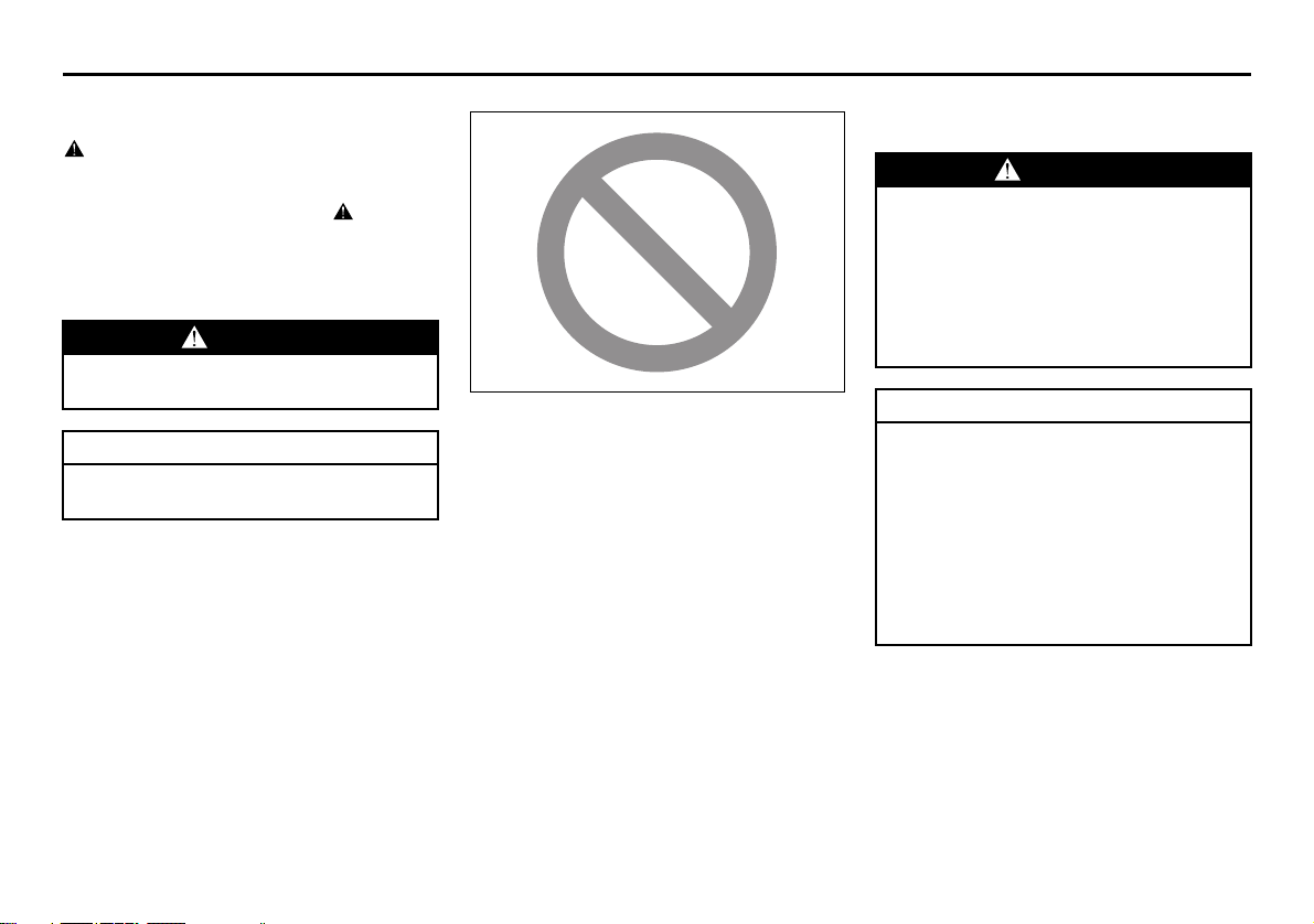
Please read this manual and follow its
instructions carefully. To emphasize special information, the symbol and the
words WARNING, CAUTION and NOTE
have special meanings. Pay special attention to the messages highlighted by these
signal words:
WARNING
Indicates a potential hazard that
could result in death or injury.
CAUTION
Indicates a potential hazard that
could result in vehicle damage.
NOTE:
Indicates special information to make
maintenance easier or instructions clearer.
75F135
The circle with a slash in this manual
means “Don’t do this” or “Don’t let this happen”.
MODIFICATION WARNING
WARNING
Do not modify this vehicle. Modification could adversely affect safety,
handling, performance or durability
and may violate governmental regulations. In addition, damage or performance problems resulting from
modification may not be covered
under warranty.
CAUTION
Improper installation of mobile communication equipment such as cellular telephones or CB (Citizen’s Band)
radios may cause electronic interference with your vehicle’s ignition system, resulting in vehicle performance
problems. Consult your SUZUKI
dealer or qualified service technician
for advice on installing such mobile
communication equipment.
Page 5

LEAK DETECTION PUMP
NOTE:
Your vehicle has a pump to regularly check
the vehicle’s evaporative emission control
system for leaks. This check is performed
approximately five hours after the engine is
turned off. During this leak check, you may
hear a sound coming from the vehicle for
several minutes. This sound is normal and
does not indicate a malfunction.
Page 6
MEMO
Page 7
INTRODUCTION
Thank you for choosing SUZUKI and welcome to our growing family. Your choice was a wise one; SUZUKI products are a great value
that will give you years of driving pleasure.
This Owner’s Manual was prepared to help you have a safe, enjoyable, and trouble-free experience with your SUZUKI. In it you will learn
about the vehicle’s operation, its safety features and maintenance requirements. Please read it carefully before operating your vehicle.
Afterwards, keep this Manual in the glove box for future reference.
Should you resell the vehicle, please leave this Manual with it for the next owner.
In addition to the Owner’s Manual, the other booklets provided with your SUZUKI explain the vehicle’s warranties. We recommend you
read them as well to familiarize yourself with this important information.
When planning the regular scheduled maintenance of your SUZUKI, we recommend you visit your local SUZUKI dealership. Their factory-trained technicians will provide the best possible service and use only genuine SUZUKI parts and accessories.
Page 8
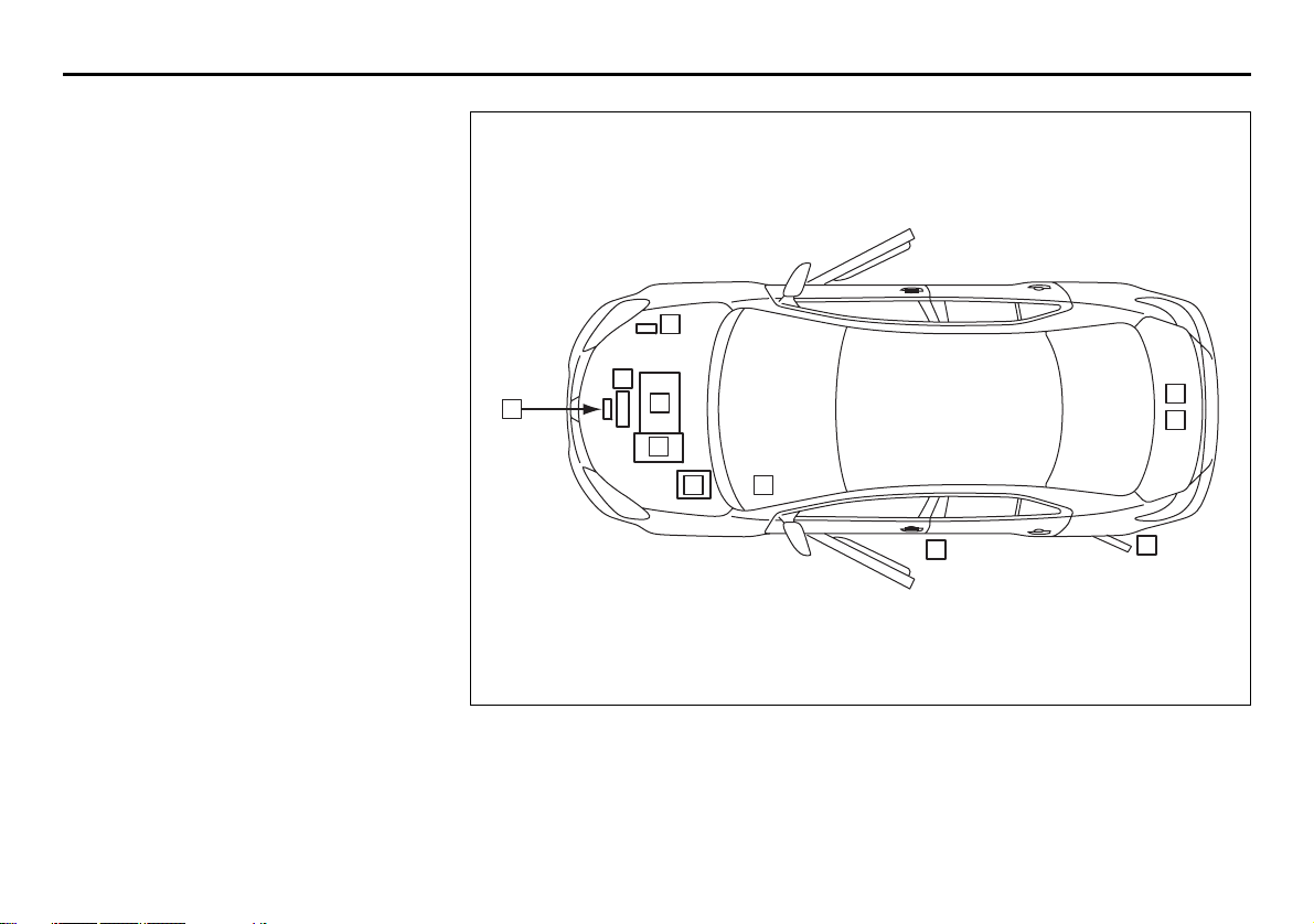
SERVICE STATION GUIDE
1. Fuel (see section 1)
2. Engine hood (see section 5)
3. Tire changing tools (see section 8)
4. Engine oil dipstick <Yellow>
(see section 7)
5. CVT fluid dipstick <Red or Orange>
(see section 7)
6. Engine coolant (see section 7)
7. Windshield washer fluid
(see section 7)
8. Battery (see section 7)
9. Tire pressure (see Tire Information
Label on driver’s door lock pillar)
10. Spare tire (see section 7)
7
6
2
4
5
3
10
8
2
9
1
57L1F002
Page 9
TABLE OF CONTENTS
FUEL RECOMMENDATION 1
California Proposition 65 Warning
WARNING
Engine exhaust, some of its constituents, and certain product components contain or emit chemicals
known to the State of California to
cause cancer and birth defects or
other reproductive harm.
BEFORE DRIVING 2
OPERATING YOUR VEHICLE 3
DRIVING TIPS 4
OTHER CONTROLS AND EQUIPMENT 5
VEHICLE LOADING AND TOWING 6
INSPECTION AND MAINTENANCE 7
EMERGENCY SERVICE 8
APPEARANCE CARE 9
GENERAL INFORMATION 10
FUSES AND PROTECTED CIRCUITS 11
SPECIFICATIONS 12
INDEX 13
Page 10
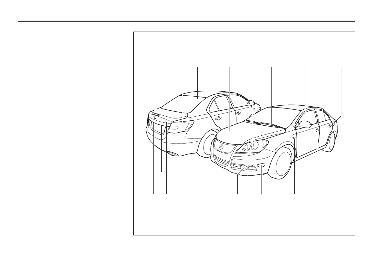
ILLUSTRATED TABLE OF CONTENTS
EXTERIOR
1. High-mount Stop Light (P.12-3)
2. Rear Combination Light (P.7-53)
3. Radio Antenna (P.5-9)
4. Engine Hood (P.5-75)
5. Headlight (P.2-100, P.7-46)
6. Windshield Wiper (P.2-107)
7. Outside Rearview Mirror (P.2-22)
8. Fuel Filler Cap (P.5-74)
9. License Plate Light (P.7-53)
10. Trunk Lid (P.2-5)
11. Front Fog Light (if equipped)
(P.2-105, P.7-50)
12. Side Marker Light (P.7-51)
13. Side Turn Signal Light (P.7-50)
14. Door Locks (P.2-3)
1 5 72 3 4 6 8
109 11 14 1312
57L1F003
Page 11
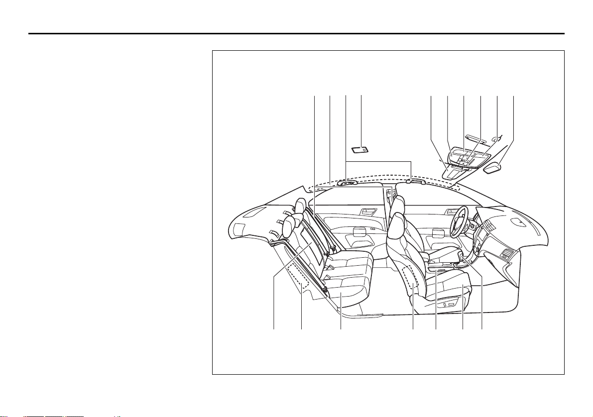
INTERIOR
1. Seat Belts (P.2-34)
2. Side Curtain Air Bags (P.2-59)
3. Assist Grip (P.5-82)
4. Interior Light (P.5-78, P.7-45)
5. Sun Visor (P.5-77)
6. Spot Light (P.5-80, P.7-46)
7. Sunroof switch (if equipped) (P.5-83)
8. Overhead Console (P.5-86)
9. Inside Rearview Mirror (if equipped)
(P.2-20)
10. Armrest (P. 5-90)/Cup Holder (P.5-87)
11. Rear Side Air Bags (P.2-59)
12. Rear Seat (P.2-29)
13. Front Side Air Bags (P.2-59)
14. Cup Holder (P.5-87)
15. Front Seats (P.2-23)
16. Gearshift Lever (P.3-13)
ILLUSTRATED TABLE OF CONTENTS
43451
68
7 92
10
13 151211 14
16
57L1F004
Page 12
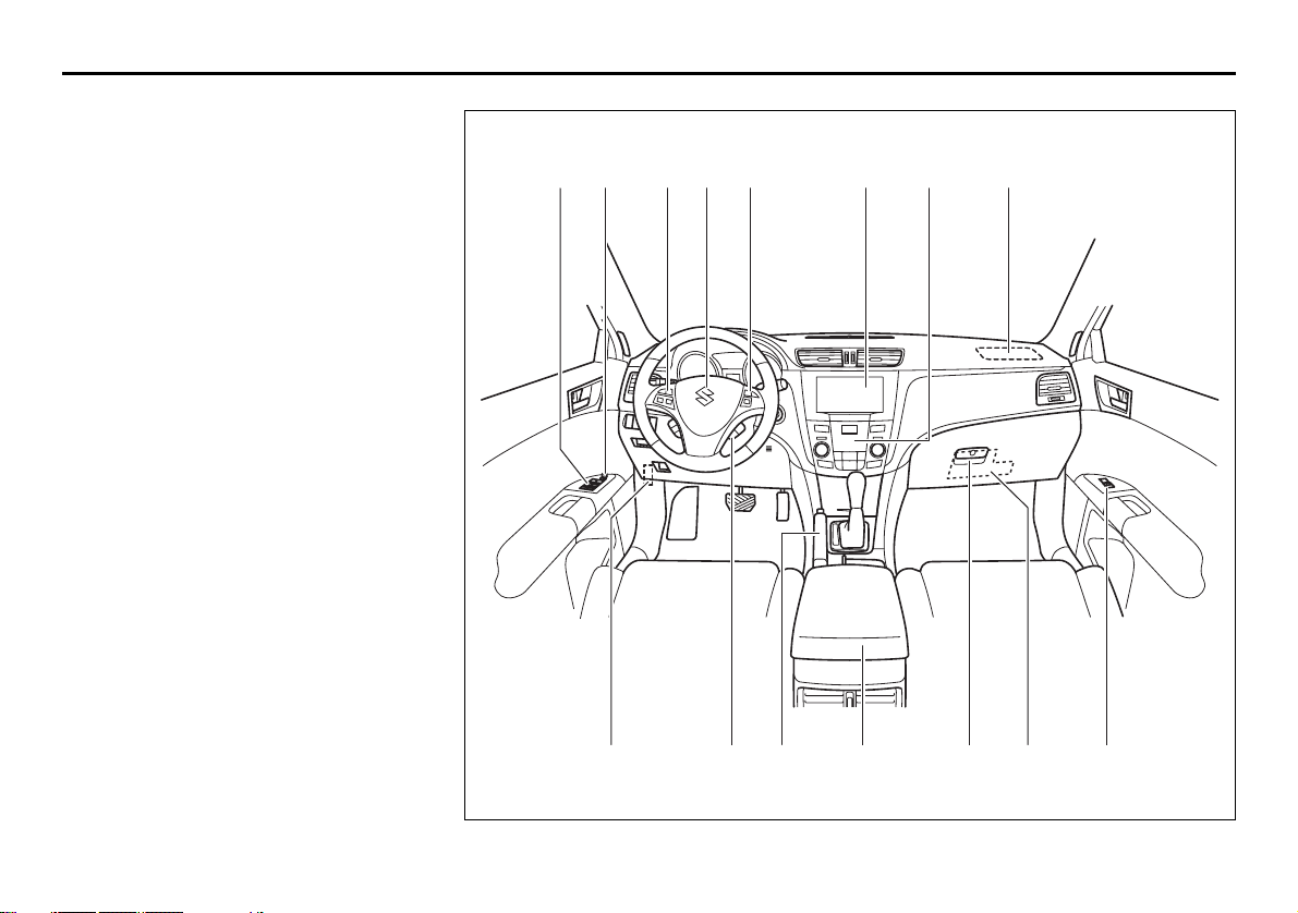
ILLUSTRATED TABLE OF CONTENTS
INSTRUMENT PANEL
1. Power Window Controls (P.2-17)/
Lock switch (P.2-18)
2. Power Mirror Control (P.2-22)
3. Remote Audio Controls (P.5-64)
4. Front Air Bags (P.2-57)
5. Cruise Control Switch (if equipped)
(P.3-21)
6. Audio (P.5-10)
7. Heating and Air Conditioning System
(P.5-1)
8. Fuse Box (P.7-40)
9. Information display switches (P.2-80)
10. Parking Brake Lever (P.3-10)
11. Center Console Box (P.5-89)/
Accessory Socket (P.5-80)
12. Glove Box (P.5-85)
1 7 443 5 62
98 10 1211 8 1
57L1F005
Page 13
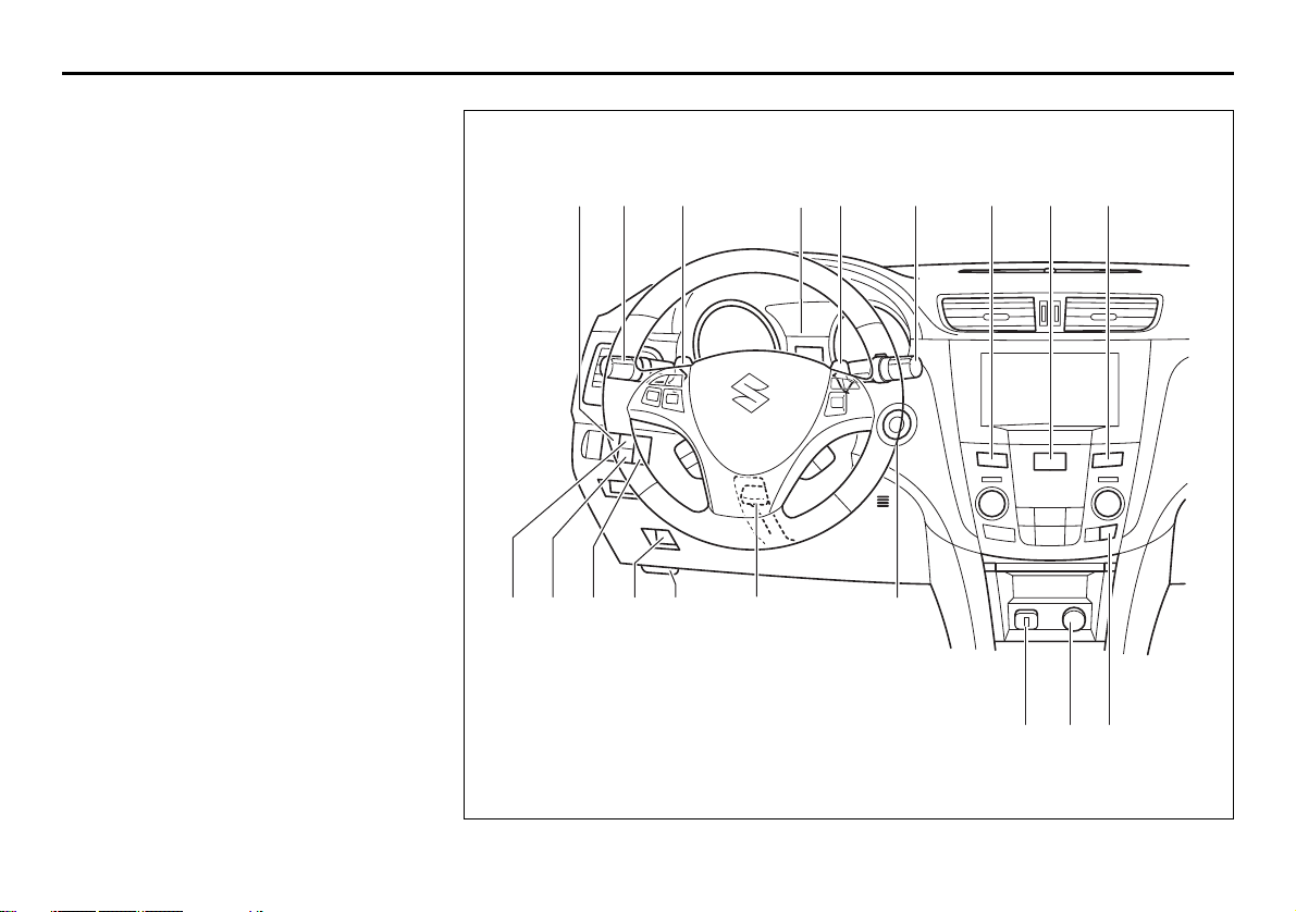
INSTRUMENT PANEL
1. Front Fog Light Switch (if equipped)
(P.2-105)
2. Lighting Control Lever (P.2-100)/
Turn Signal Control Lever (P.2-105)
3. Shift Paddles (if equipped) (P.3-17)
4. Instrument Cluster (P.2-68)
5. Windshield Wiper and Washer Lever
(P.2-107)
6. Front Seat Heater Switch
(if equipped) (P.2-28)
7. Hazard Warning Switch (P.2-106)
®
8. ESP
9. Parking Sensor Switch (if equipped)
10. 2WD/i-AWD (intelligent All Wheel
11. Trunk lid unlatch switch (P.2-5)
12. Engine Hood Release Handle
13. Tilt/Telescoping/Steering Lock Lever
14. Engine Switch (P.3-2)
15. Universal Serial Bus (USB) Socket
16. Accessory Socket (P.5-80)/
17. Heated Rear Window and Heated
OFF Switch (P.3-33)
(P.3-26)
Drive) Switch (if equipped) (P.3-19)
(P.5-75)
(P.2-110)
(P.5-81)
Cigarette Lighter (if equipped) (P.5-81)
Outside Rearview Mirrors Switch
(if equipped) (P.2-111)
ILLUSTRATED TABLE OF CONTENTS
1 32 4 7 6
8
12119 10
13
3 6
5
14
171615
57L1F006
Page 14
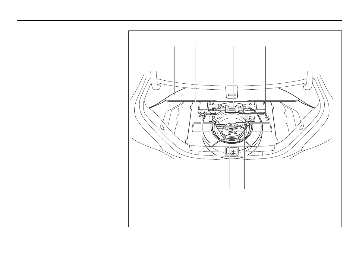
ILLUSTRATED TABLE OF CONTENTS
TIRE CHANGING TOOL
1. Floorboard (P.8-1)
2. Luggage under-box (P.8-1)
3. Jack (P.8-1)
4. Wheel Brace (P.8-1)
5. Tow hook (P.5-96)
6. Spare Tire (P.7-34, P.8-1)
7. Jack Handle (P.8-1)
1 32 4
75 6
57L1F007
Page 15
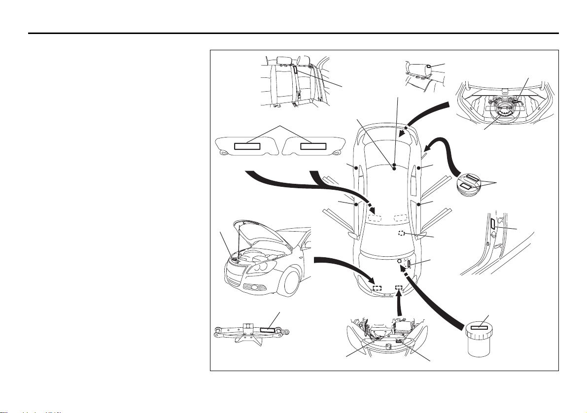
LOCATION OF WARNING
MESSAGES
Read and follow all of the warnings (labels
etc.) on your vehicle. Make sure you
understand all of them. Keep them on the
vehicle. Do not remove the messages for
any reason. If a label comes off or the
messages become difficult to be read,
have it corrected by your SUZUKI dealer.
11
12
13
1
13
11
9
1. Air bag warning labels
(on both sun visors)
2. Jacking warning label
3. Fuel filler cap message
4. Brake fluid cap message
5. Engine cooling fan warning label
6. Radiator cap warning label
7. Air conditioner warning label
8. Battery label
9. Compact spare tire warning label
(if equipped)
10. Side air bag warning label
11. Rear center head restraint warning
label
12. Jacking instruction warning label
13. Rear center seat belt warning label
14. Floor mat warning label (if equipped)
&TKXGT 2CUUGPIGT
7
2
10
10
6
10
3
10
10
14
8
4
5
57L1F008
Page 16
MEMO
Page 17
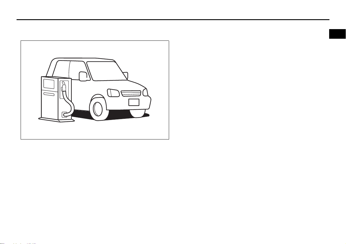
FUEL RECOMMENDATION
65D394
FUEL RECOMMENDATION
Fuel Recommendation ........................................................ 1-1
1
Page 18
FUEL RECOMMENDATION
Fuel Recommendation
60A004
Your vehicle requires regular unleaded
gasoline with a minimum rating of 87 pump
octane ((R + M)/2 method). In some areas,
the only fuels that are available are oxygenated fuels.
Oxygenated fuels which meet the minimum octane requirement and the requirements described below may be used in
your vehicle without jeopardizing the New
Vehicle Limited Warranty.
NOTE:
Oxygenated fuels are fuels which contain
oxygen-carrying additives such as MTBE
or alcohol.
Gasoline Containing MTBE
Unleaded gasoline containing MTBE
(methyl tertiary butyl ether) may be used in
your vehicle if the MTBE content is not
greater than 15%. This oxygenated fuel
does not contain alcohol.
Gasoline/Ethanol blends
Blends of unleaded gasoline and ethanol
(grain alcohol), also known as gasohol,
may be used in your vehicle if the ethanol
content is not greater than 10%.
Gasoline/Methanol blends
Fuels containing 5% or less methanol
(wood alcohol) may be suitable for use in
your vehicle if they contain cosolvents and
corrosion inhibitors. Do NOT USE fuels
containing more than 5% methanol under
any circumstances. Fuel system damage
or vehicle performance problems resulting
from the use of such fuels are not the
responsibility of SUZUKI and may not be
covered under the New Vehicle Limited
Warranty.
Fuel Pump Labeling
In some states, pumps that dispense oxygenated fuels are required to be labeled for
the type and percentage of oxygenate and
whether important additives are present.
Such labels may provide enough information for you to determine if a particular
blend of fuel meets the requirements listed
above. In other areas, pumps may not be
clearly labeled as to the content or type of
oxygenate and additives. If you are not
sure that the fuel you intend to use meets
these requirements, check with the service
station operator or the fuel supplier.
NOTE:
To help clean the air, SUZUKI recommends you use the oxygenated fuels.
However, if you are not satisfied with the
driveability or fuel economy of your vehicle
when you are using an oxygenated fuel,
switch back to the regular unleaded gasoline.
CAUTION
Be careful not to spill fuel containing
alcohol while refueling. If fuel is
spilled on the vehicle body, wipe it up
immediately. Fuels containing alcohol can cause paint damage, which is
not covered under the New Vehicle
Limited Warranty.
1-1
Page 19
60G404
BEFORE DRIVING
BEFORE DRIVING
Keys .................................................................................... 2-1
Immobilizer System .......................................................... 2-2
Door Locks ........................................................................ 2-3
Keyless Start System Remote Controller ....................... 2-6
Theft Deterrent Alarm System ......................................... 2-14
Windows ............................................................................ 2-17
Mirrors ................................................................................ 2-20
Front Seats ........................................................................ 2-23
Front Seat Heater (if equipped) ........................................ 2-28
Rear Seats .......................................................................... 2-29
Seat Belts and Child Restraint Systems ......................... 2-34
Supplemental Restraint System (air bags) ..................... 2-55
Instrument Cluster ............................................................ 2-68
Warning and Indicator Lights .......................................... 2-69
Speedometer ..................................................................... 2-78
Tachometer ........................................................................ 2-78
Fuel Gauge ......................................................................... 2-78
Temperature Gauge .......................................................... 2-79
Brightness Control ............................................................ 2-79
Information Display ........................................................... 2-80
Lighting Control Lever ...................................................... 2-100
Front Fog Light Switch (if equipped) .............................. 2-105
Turn Signal Control Lever ................................................ 2-105
Hazard Warning Switch .................................................... 2-106
Rain-sensing Wipers and Washer Lever ......................... 2-107
Tilt/Telescoping/Steering Lock Lever (if equipped) ....... 2-110
Horn .................................................................................... 2-111
Heated Rear Window and Heated Outside
Rearview Mirrors (if equipped) Switch ............................ 2-111
2
Page 20
BEFORE DRIVING
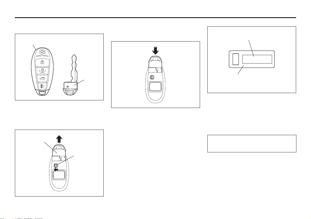
Keys
(1)
Your vehicle comes with two identical keyless start system remote controllers (1),
each with a detachable key (2) housed
inside.
(2)
EXAMPLE
(2)
57L21001
(3)
To remove the key from the remote controller, slide the lock (3) in the direction of the
arrow and pull out the key.
57L21016
To stow the key into the remote controller,
push the key in the remote controller until
you hear a click.
(4)
(5)
57L21003
The key identification number (4) is
stamped on a metal tag (5) provided with
the keys. Keep the tag in a safe place. If
you lose your keys, you will need this number to have new keys made. Write the
number below for your future reference.
KEY NUMBER:
2-1
57L21002
Page 21
BEFORE DRIVING
Immobilizer System
WARNING
Never leave the keyless start system
remote controller in the vehicle when
leaving the vehicle.
The immobilizer system is an anti-theft feature, which checks whether the keyless
start system remote controller that is communicating via radio waves with the vehicle
has been registered to the vehicle’s keyless start system. If the remote controller is
not a registered one, the system will refuse
to start the engine using it.
Immobilizer/Keyless Start System
Warning Light
85K2210
This light is on the instrument cluster.
• When you press the engine switch to
change the ignition mode to “ON”, the
light comes on briefly so you can check
that the light is working. If the light is
flashing, the engine cannot be started.
• The light also flashes when the “remote
controller outside” warning works.
NOTE:
• The immobilizer/keyless start system is
normal if this light goes out in 2 seconds
after pressing the engine switch to
change the ignition mode to “ON”. If the
light fails to go out in this period, there is
something wrong with the system. There
is also a problem with the system if the
light remains on for 5 seconds after the
engine switch is pressed when the
switch is in any other ignition mode than
“ON”.
• Illumination or flashing of the light may
be accompanied by a message on the
information display in the instrument
cluster.
NOTE:
• If you lose your keyless start system
remote controller, see your SUZUKI
dealer as soon as possible to have the
lost one deactivated, then have the new
remote controller made by them.
• If you own other vehicles with keyless
start system remote controller, keep
those remote controllers away from the
engine switch when using your SUZUKI,
or the engine may not be started
because they may interfere with your
SUZUKI’s immobilizer system.
• In case of attaching any metal objects to
the keyless start system remote controller, it may not start the engine.
CAUTION
The keyless start system remote controller is a sensitive electronic instrument. To avoid damaging the keyless
start system remote controller:
• Do not expose it to impacts, moisture or high temperature such as
on the dashboard under direct sunlight.
• Keep the keyless start system
remote controller away from magnetic objects.
1. For USA
This device complies with Part 15 of the
FCC Rules. Operation is subject to the following two conditions:
(1) this device may not cause harmful
interference, and (2) this device must
accept any interference received, including
interference that may cause undesired
operation.
NOTE:
Changes or modifications not expressly
approved by the party responsible for compliance could void the user’s authority to
operate the equipment.
2-2
Page 22
BEFORE DRIVING
2. For Canada
This device complies with Industry Canada
Standard RSS-210. Operation is subject to
the following two conditions:
(1) this device may not cause interference,
and (2) this device must accept any interference, including interference that may
cause undesired operation of the device.
Door Locks
WARNING
Always lock all doors when driving.
Locking the doors helps to prevent
occupants from being thrown from
the vehicle in the event of an accident. It also helps prevent unintended opening of the doors.
Side Door Locks
(1)
(4)
(1) LOCK
(2) UNLOCK
(3) Rear
(4) Front
To lock a driver’s door from outside the
vehicle:
• Insert the key and turn the top of the key
toward the front of the vehicle, or
(2)
(3)
57L21004
• Turn the lock knob forward, then pull and
hold the door handle as you close the
door.
To lock a passenger’s door from outside
the vehicle, turn the lock knob forward,
then pull and hold the door handle as you
close the door.
NOTE:
If the remote controller is left within the
“inside sensing area”, the locking of the
front doors will be cancelled.
To unlock a driver’s door from outside the
vehicle, insert the key and turn the top of
the key toward the rear of the vehicle.
EXAMPLE
(1)
(2)
57L21005
(1) LOCK
(2) UNLOCK
To lock a door from inside the vehicle, turn
the lock knob forward. Turn the lock knob
rearward to unlock the door.
2-3
Page 23
BEFORE DRIVING
To lock a rear door from outside the vehicle, turn the lock knob forward and close
the door. You do not need to pull and hold
the door handle as you close the door.
Power Door Locking System
You can lock and unlock all the doors
simultaneously by:
• Turning the key in a driver’s door lock, or
• Pushing the power door locking switch
located on the driver’s side or the front
passenger’s side door panel.
(2)
(1)
(3)
(4)
57L21006
(1) LOCK
(2) UNLOCK
(3) Rear
(4) Front
(when using the key)
To lock all the doors simultaneously, insert
the key in a driver’s door lock and turn the
top of the key toward the front of the vehicle once.
To unlock all the doors simultaneously,
insert the key in a driver’s door lock and
turn the top of the key toward the rear of
the vehicle twice.
To unlock only one of the driver’s doors,
insert the key in that door lock and turn the
top of the key toward the rear of the vehicle
once.
Driver’s side
EXAMPLE
(2)
(1) LOCK
(2) UNLOCK
(1)
(5)
57L21007
Front passenger’s side
EXAMPLE
(1)
(1) LOCK
(2) UNLOCK
(when using the power door locking
switch)
To lock or unlock all the doors simultaneously, depress the front or rear of the
switch (5) or (6), respectively.
NOTE:
• You can also lock or unlock all doors by
operating the remote controller. Refer to
“Keyless Start System Remote Controller” in this section.
• You can also lock or unlock all doors by
pushing the request switch on the door
handle. Refer to “Keyless Start System
Remote Controller” in this section.
(2)
(6)
57L21008
2-4
Page 24
BEFORE DRIVING
Child Lock System (rear doors)
EXAMPLE
(2)
(1)
57L21009
(1) LOCK
(2) UNLOCK
Each of the rear doors is equipped with a
child lock which can be used to help prevent unwanted opening of the door from
inside the vehicle. When the lock lever is in
the “LOCK” position (1), the rear door can
only be opened from outside. When the
lock lever is in the “UNLOCK” position (2),
the rear door can be opened from inside or
outside.
WARNING
Be sure to place the child lock in the
“LOCK” position whenever children
are seated in the rear.
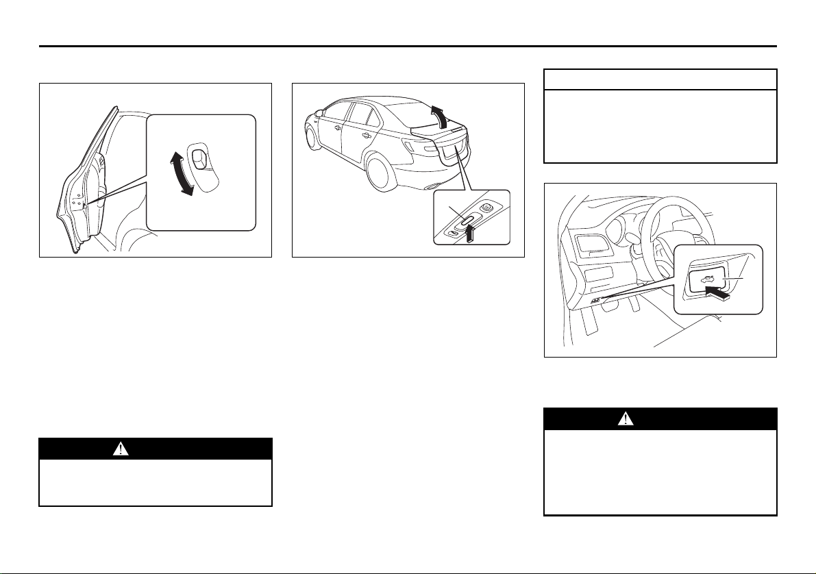
Trunk Li d
(1)
57L21010
To open the trunk lid, lift it while pressing
the trunk lid request switch (1).
The trunk lid request switch (1) operates
when the keyless start system remote controller is within the switch’s operating
range.
If the remote controller is within the operating range, you can also unlatch and let the
trunk lid slightly open by holding the
“TRUNK LID UNLOCK” button on the
remote controller pressed for more than 1
second. Refer to “Keyless Start System
Remote Controller” in this section.
The trunk lid request switch (1) operates
only to open the trunk lid.
If you close the trunk lid with the keyless
start system remote controller left in the
trunk with all the doors locked, the trunk
will be automatically unlatched.
CAUTION
Check that you have the remote controller whenever you close the trunk
lid, or there is a risk of leaving the
remote controller inside the closed
trunk lid.
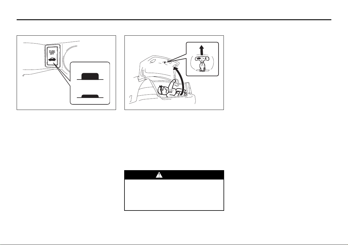
(2)
57L21011
You can unlock the lid by pushing the trunk
lid unlatch switch (2).
WARNING
Always make sure that the trunk lid is
closed and latched securely. Otherwise, it may open unexpectedly while
driving. Completely closing it also
helps keep exhaust gases from entering the car.
2-5
Page 25
BEFORE DRIVING
Trunk Lid Lock Switch (if equipped)
(3)
(4)
57L21061
(3) UNLOCK
(4) LOCK
This switch is inside the glove box. If this
switch is pushed to the down position, the
trunk lid is locked and cannot be opened.
Push the switch again to unlock the lid.
Internal Trunk Release
EXAMPLE
57L21012
There is a release lever located inside the
trunk, on the rear part of the trunk lid. This
lever is for emergency use so that if a person, such as a child, gets trapped in the
trunk compartment, he can exit the vehicle.
The lever glows in the dark, after a brief
exposure to ambient light, so it can be
found easily. It is operated by pulling it in
the direction of the arrow.
WARNING
To help avoid situations where someone might get trapped in the trunk,
keep your vehicle locked when unattended, and do not allow anyone to
play in the trunk.
Keyless Start System Remote
Controller
Keyless Start System Remote
Controller
The remote controller enables the following
operations:
• You can lock or unlock the doors by
operating the LOCK/UNLOCK buttons
on the remote controller. Refer to the
explanation in this section.
• You can lock or unlock the doors by
pushing the request switch on the door
handle. For details, refer to the explanation in this section.
• You can unlatch and let the trunk lid
slightly open by pushing and holding the
“TRUNK LID UNLOCK” button on the
remote controller. Refer to the explanation in this section.
2-6
Page 26
BEFORE DRIVING
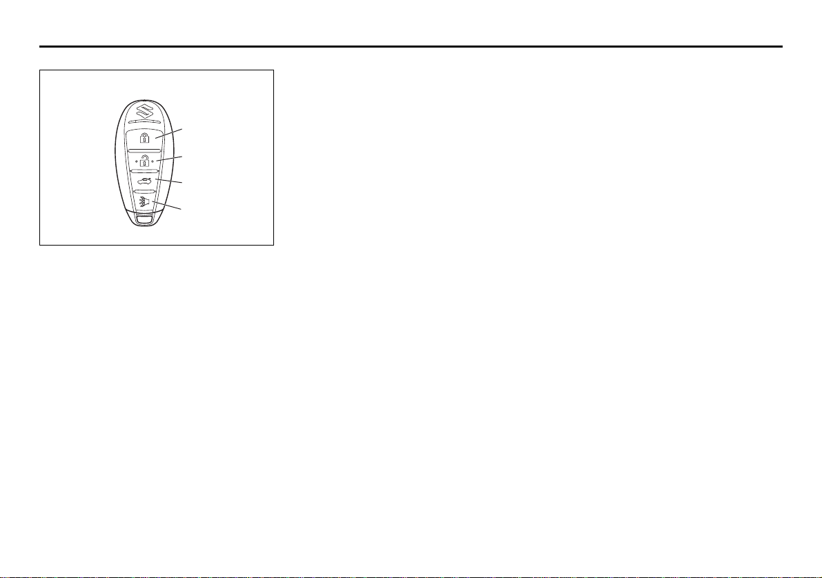
EXAMPLE
(1)
(2)
(3)
(4)
57L21013
(1) “LOCK” button
(2) “UNLOCK” button
(3) “TRUNK LID UNLOCK” button
(4) “PANIC” button
“LOCK” button (1) / “UNLOCK” button
(2) function
You can lock or unlock all doors simultaneously by operating the remote controller
near the vehicle.
• To lock the doors, push the “LOCK” button (1).
• To unlock the driver’s door, push the
“UNLOCK” button (2) once.
• To unlock other doors, wait a second or
two, then push the “UNLOCK” button (2)
a second time. If you “double-click” too
fast, the doors will not unlock.
The turn signal lights will flash once when
the doors are locked.
When the doors are unlocked:
• The turn signal lights will flash twice.
• If the interior light switch is in the
“DOOR” position, the interior light will
turn on for about 15 seconds and then
fade out. If you press the engine switch
during this time, the light will start to fade
out immediately.
Be sure the doors are locked after you
operate the “LOCK” button (1).
If no door is opened within about 30 seconds after the “UNLOCK” button (2) is
operated, the doors will automatically lock
again.
NOTE:
• The maximum operating distance of the
remote controller is about 5 m (16 ft.),
but this can vary depending on the surroundings, especially near other transmitting devices such as radio towers or
CB (Citizen’s Band) radios.
• The door locks cannot be operated with
the remote controller if the ignition mode
has been changed to “LOCK” (OFF) with
the engine switch, or if any door is open.
If any door is open, you cannot lock the
door by operating the remote controller,
however YOUCANunlock the door.
• You cannot lock the door unless all of the
door are closed completely.
• If you lose one of the remote controllers,
ask your SUZUKI dealer as soon as possible for a replacement. Be sure to have
your dealer program the new remote
controller code in your vehicle’s memory
so that the old code is erased.
“TRUNK LID UNLOCK” button (3) function
Push and hold the “TRUNK LID UNLOCK”
button pressed for more than 1 second; the
trunk lid will be unlatched and open
slightly.
NOTE:
The trunk lid cannot be operated with the
remote controller if the engine switch is in
any other ignition mode than “LOCK”
(OFF).
“PANIC” button (4) function
This function is to get the attention of others.
Press the “PANIC” button (4) for more than
1 second. The headlights and taillights will
blink for about 30 seconds. Also, the horn
will sound intermittently for about 30 seconds at the same time.
To cancel the “PANIC” mode, press any
button (PANIC, LOCK, UNLOCK or
TRUNK LID UNLOCK) on the remote controller. You can also press the engine
switch to cancel the “PANIC” mode.
NOTE:
The “PANIC” button function will not activate when you have changed the ignition
mode to “ACC” by pressing the engine
switch.
2-7
Page 27
BEFORE DRIVING
Keyless unlocking/locking using the
request switches
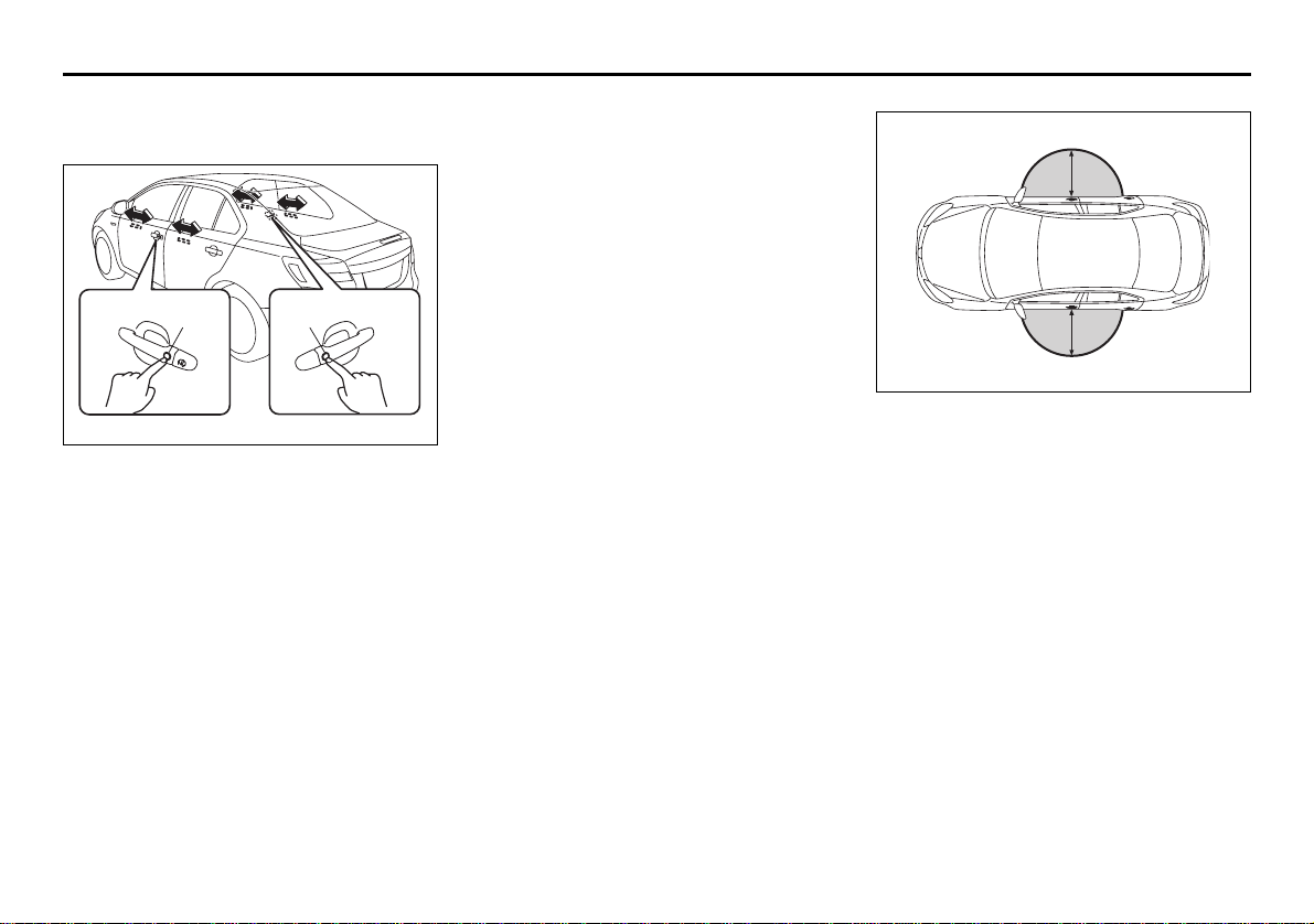
(1) (1)
EXAMPLE
57L21014
When the remote controller is within the
operating range described in this section,
you can lock or unlock the doors by pushing the request switch (1) on the door handle of the driver’s door or front passenger’s
door.
To lock all doors when all doors are
unlocked:
• Push the request switch on one of the
door handles once.
The turn signal lights will flash once when
the doors are locked.
To unlock a door or all doors:
• Push the request switch on the door
handle once to unlock only one door.
• Push the request switch on the door
handle twice to unlock all doors.
When the doors are unlocked:
• The turn signal lights will flash twice.
• If the interior light switch is in the
“DOOR” position, the interior light will
turn on for about 15 seconds and then
fade out. If you press the engine switch
during this time, the light will start to fade
out immediately.
Be sure the doors are locked after you
operate the request switch to lock the
doors.
NOTE:
• The door locks cannot be operated by
the request switch under the following
conditions:
– If any door is open or is not completely
closed.
– If the ignition mode has been changed
to “LOCK” (OFF) by pressing the
engine switch.
• If no doors are opened within about 30
seconds after unlocking the doors by
pushing the request switch, the doors
will be locked again automatically.
(2)
(2)
57L21015
(2) 80 cm (2 1/2 feet)
When the remote controller is within
approximately 80 cm (2 1/2 feet) from a
front door handle, you can lock or unlock
the doors by pushing the request switch.
2-8
Page 28
BEFORE DRIVING
NOTE:
• If the remote controller is outside the
request switch operating range
described above, you will not be able to
operate the request switch.
• If the battery of the remote controller
runs down or there are strong radio
waves or noise, the request switch operating range may be reduced or the
remote controller may be inoperative.
• If the remote controller is too close to the
door, the request switches may not operate.
• If a spare remote controller is in the vehicle, the request switches may not operate normally.
• The remote controller will only operate a
request switch if it is within the switch’s
operating range. For example, if the
remote controller is within the operating
range of the driver’s door request switch
but not the front passenger’s door
request switch, the driver’s door switch
can be operated but the front passenger’s door switch cannot be operated.
CAUTION
The remote controller is a sensitive
electronic instrument. To avoid damaging the remote controller:
• Do not expose it to impacts, moisture or high temperature such as by
leaving it on the dashboard under
direct sunlight.
• Keep the remote controller away
from magnetic objects such as a
television.
NOTE:
The keyless start system may not function
correctly in certain environments or under
certain operating conditions such as the
following:
• When there are strong signals coming
from a television, power station or a cellular phone.
• When the remote controller is in contact
with or covered by a metal object.
• When a radio wave type remote keyless
entry is used nearby.
• When the remote controller is placed
near an electronic device such as personal computer.
Some additional precautions you should
take and information you should be aware
of are:
• Make sure the key is stowed in the
remote controller. If the remote controller
becomes unreliable, you will not be able
to lock or unlock the doors, or start the
engine.
• Be sure that the driver always carries the
remote controller.
• If you lose one of the remote controllers,
ask an authorized SUZUKI dealer as
soon as possible for a replacement. Be
sure to have your dealer program the
new remote controller code in your vehicle’s memory so that the old code is
erased, or perform the programming procedure yourself according to the instructions in this section.
• You can use up to four remote controllers
and keys for your vehicle. Ask an authorized SUZUKI dealer for details.
• The battery life of the remote controller
is about two years, but it can vary
depending on usage conditions.
2-9
Page 29
BEFORE DRIVING
(1)
Request Switch Warning Buzzer
This outside buzzer beeps for about 2 seconds in the following conditions to warn
you that the request switch is not working:
• The request switch is pressed after all
doors are closed with the ignition mode
changed to “ACC” or “ON” by pressing
the engine switch.
• The request switch is pressed in any of
the following conditions after changing
the ignition mode to “LOCK” (OFF) by
pressing the engine switch.
– The remote controller is left inside the
vehicle.
– Any of the doors is open.
Press the request switch again after doing
the following:
With the ignition mode changed to “LOCK”
(OFF) by pressing the engine switch, bring
out the remote controller if it is inside the
vehicle and check that all doors are completely closed.
Remote Controller Reminder Function
When you lock a door without using the
key, this function prevents it from being
locked if the remote controller is left inside
the vehicle.
With the remote controller inside the vehicle, locking of the driver’s and passenger’s
doors made with the power door locking
system or door lock knobs will be cancelled if either of the doors is open.
NOTE:
• Whenever you lock a door without using
the key, check that you have the remote
controller with you. This is a good habit
to prevent locking a door with the remote
controller left behind.
• The remote controller reminder function
is activated when you press the engine
switch to change the ignition mode to
“ACC” or “ON” anywhere the remote
controller is placed.
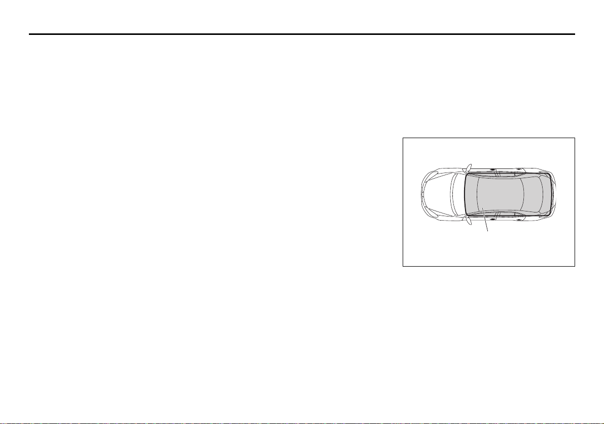
Vehicle Inside Area Where Request
Switch Warning Buzzer/Remote Controller Reminder Function Works
Inside the vehicle, the remote controller
may be located in any place within the indicated “inside sensing area” (1) (not including the instrument panel top and trunk) for
the request switch warning buzzer/remote
controller reminder function to work.
57L21017
2-10
Page 30

BEFORE DRIVING
NOTE:
• Even with the remote controller within
the “inside sensing area”, the request
switch warning buzzer/remote controller
reminder function may not work under
any of the following conditions as the
presence of the remote controller may
not be sensed:
– The battery of the remote controller is
low.
– The remote controller is influenced by
strong radio waves or noise.
– The remote controller is in contact with
or covered by a metallic object.
– The remote controller is in the glove
box or a stowage for small articles
such as a door pocket.
– The remote controller is on the top or
in front of the instrument panel, in the
sun visor pocket or on the floor.
• The remote controller may be sensed
under any of the following conditions
even when the controller is not within the
“inside sensing area”. The request
switch warning buzzer/remote controller
reminder function will then work.
– The remote controller is outside the
vehicle but very close to it.
– The remote controller is on the instru-
ment panel top or in the trunk.
Keyless unlocking/locking using the
trunk lid request switch
(1)
57L21010
(2)
57L21018
(2) 80 cm (2 1/2 feet)
When the remote controller is within
approximately 80 cm (2 1/2 feet) from the
trunk lid request switch, you can open the
trunk lid by pushing and holding the trunk
lid request switch (1).
NOTE:
• If the remote controller is outside the
trunk lid request switch operating range
described above, you will not be able to
operate the switch.
• If the battery of the remote controller
runs down or there are strong radio
waves or noise, the trunk lid request
switch operating range may be reduced
or the remote controller may be inoperative.
• If the remote controller is too close to the
trunk lid, the trunk lid request switch may
not operate.
• If a spare remote controller is in the
trunk, the trunk lid request switch may
not operate normally.
CAUTION
The remote controller is a sensitive
electronic instrument. To avoid damaging the remote controller:
• Do not expose it to impacts, moisture or high temperature such as by
leaving it on the dashboard under
direct sunlight.
• Keep the remote controller away
from magnetic objects such as a
television.
2-11
Page 31

BEFORE DRIVING
NOTE:
The keyless start system may not function
correctly in certain environments or under
certain operating conditions such as the
following:
• When there are strong signals coming
from a television, power station or a cellular phone.
• When the remote controller is in contact
with or covered by a metal object.
• When a radio wave type remote keyless
entry is used nearby.
• When the remote controller is placed
near an electronic device such as personal computer.
Some additional precautions you should
take and information you should be aware
of are:
• Make sure the key is stowed in the
remote controller. If the remote controller
becomes unreliable, you will not be able
to lock or unlock the doors, or start the
engine.
• Be sure that the driver always carries the
remote controller.
• If you lose one of the remote controllers,
ask an authorized SUZUKI dealer as
soon as possible for a replacement. Be
sure to have your dealer program the
new remote controller code in your vehicle’s memory so that the old code is
erased, or perform the programming procedure yourself according to the instructions in this section.
• You can use up to four remote controllers
and keys for your vehicle. Ask an authorized SUZUKI dealer for details.
• The battery life of the remote controller
is about two years, but it can vary
depending on usage conditions.
Remote Controller Reminder Function
(for Trunk)
This function prevents the remote controller from being left under a locked trunk lid.
• If you attempt to lock the trunk lid with
the remote controller left inside the trunk
and the vehicle in the following condition,
the function automatically unlocks and
slightly opens the lid:
– Vehicle is parked with all doors closed
and locked.
CAUTION
Check that you have the remote controller whenever you close the trunk
lid, or there is a risk of leaving the
remote controller inside the closed
trunk lid.
Trunk Inside Area Where Remote Controller Reminder Function (for Trunk)
Works
(1)
57L21019
2-12
Page 32

BEFORE DRIVING
NOTE:
• Even with the remote controller within
the “trunk inside sensing area” (1), the
remote controller reminder function (for
trunk) may not work under any of the following conditions as the presence of the
remote controller may not be sensed:
– The battery of the remote controller is
low.
– The remote controller is influenced by
strong radio waves or noise.
– The remote controller is in contact with
or covered by a metallic object.
– The remote controller is in a corner of
the trunk.
• The remote controller may be sensed
under the following condition even when
the controller is not within the “trunk
inside sensing area”. The remote controller reminder function (for trunk) will
then work.
– The remote controller is outside the
vehicle but very close to the trunk.
Replacement of the battery
If the remote controller becomes unreliable, replace the battery.
To replace the battery of the remote controller:
EXAMPLE
57L21022
1) Insert a flat blade screwdriver covered
with a soft cloth in the slot of the remote
controller and pry it open.
EXAMPLE
(1)
57L21023
(1) Lithium disc type battery:
CR2032 or equivalent
2) Replace the battery (1) so its + terminal
faces the bottom of the case as shown
in the illustration.
3) Close the remote controller firmly.
4) Make sure the door locks can be operated with the remote controller.
5) Dispose of the used battery properly
according to applicable rules or regulations. Do not dispose of lithium batteries with ordinary household trash.
2-13
Page 33

BEFORE DRIVING
WARNING
Swallowing a lithium battery may
cause serious internal injury. Do not
allow anyone to swallow a lithium
battery. Keep lithium batteries away
from children and pets. If swallowed,
contact a physician immediately.
CAUTION
The remote controller is a sensitive
electronic instrument. To avoid damaging it, do not expose it to dust or
moisture or tamper with internal
parts.
1. For USA
This device complies with Part 15 of the
FCC Rules. Operation is subject to the following two conditions:
1) This device may not cause harmful
interference, and
2) This device must accept any interference received, including interference
that may cause undesired operation.
NOTE:
Changes or modifications not expressly
approved by the party responsible for compliance could void the user’s authority to
operate the equipment.
2. For Canada
This device complies with Industry Canada
Standard RSS-210. Operation is subject to
the following two conditions:
1) This device may not cause interference,
and
2) This device must accept any interference, including interference that may
cause undesired operation of the
device.
The term “IC:” before the certification/registration number only signifies that the
Industry Canada technical specifications
were met.
Theft Deterrent Alarm System
The theft deterrent alarm system is armed
in about 20 seconds after you lock the
doors using the keyless start system
remote controller or by pushing the request
switch on the driver’s or front passenger’s
door handle. (The system, however, is not
armed when the engine hood or trunk lid is
open.)
Once the system is armed, any attempt to
open a door by using any other means (*)
than the keyless start system remote controller or the request switch will cause the
alarm to be triggered.
* These means include the following:
–The key
– The lock lever on a door
– The power door lock knob
– The trunk lid unlatch switch
– The engine hood release handle
2-14
Page 34

BEFORE DRIVING
NOTE:
• The theft deterrent alarm system generates alarms when any of the predetermined conditions is met. However, the
system does not have any function of
blocking unauthorized entry into your
vehicle.
• Always use the keyless start system
remote controller or the request switch to
unlock the doors when the theft deterrent alarm system has been armed.
Using a key instead will trigger the
alarm.
• If a person who does not know the theft
deterrent alarm system is going to drive
your vehicle, we recommend you to
explain the system and its operation to
the person, or disable the system beforehand. Mistakenly triggering the alarm
may cause a nuisance to others.
• Even if the theft deterrent alarm system
is armed, you should still be careful to
guard against theft. Do not leave money
or things of value in your vehicle.
How to arm the theft deterrent alarm
system (when enabled)
Lock the doors using the keyless start system remote controller or by pushing the
request switch. The theft deterrent light (1)
will start flashing, and the theft deterrent
alarm system will be armed in about 20
seconds.
While the system is being armed, the indicator continues to flash at approximately 2second intervals.
(1)
57L30094
NOTE:
• To prevent the alarm from being accidentally triggered, avoid arming it while anyone remains inside the vehicle. The
alarm will be triggered if any person
inside unlocks a door by operating the
lock lever or power door locking switch.
• The theft deterrent alarm system is not
armed when all doors are locked using
the key from outside, or using the door
lock levers or the power door locking
switch from inside.
• If the timer locking function is activated,
the system will be automatically armed
at the preset time unless the theft deterrent alarm system has been disabled.
How to disarm the theft deterrent alarm
system
Simply unlock the doors using the keyless
start system remote controller or by pushing the request switch. The theft deterrent
light will go out, indicating that the theft
deterrent alarm system is disarmed.
2-15
Page 35

BEFORE DRIVING
How to stop the alarm
Should the alarm be triggered accidentally,
change the ignition mode to “ON” by pressing the engine switch. The alarm will then
stop.
NOTE:
• Even after the alarm has stopped, if you
lock the doors using the keyless start
system remote controller or by pushing
the request switch, the theft deterrent
alarm system will be rearmed with a
delay of about 20 seconds.
• If you disconnect the battery while the
theft deterrent alarm system is in the
armed condition or the alarm is actually
in operation, the alarm will be triggered
or re-triggered when the battery is then
reconnected, although, in the latter case,
the alarm remains stopped for the period
between disconnection and reconnection of the battery.
• Even after the alarm has stopped at the
end of the predetermined operation time,
it will be triggered again if any door is
opened without disarming the theft
deterrent alarm system.
Checking whether the alarm has been
triggered during parking
If the alarm was triggered due to an unauthorized entry into the vehicle and you then
change the ignition mode to “ON” by pressing the engine switch, the theft deterrent
light will flash rapidly for about 8 seconds
and a buzzer will beep 4 times during this
period. If this happens, check whether your
vehicle has been broken into while you
were away from it.
Enabling and disabling the theft deterrent alarm system
The theft deterrent alarm system can be
either “enabled” or “disabled”.
When enabled (factory setting)
When the system is enabled, it causes the
hazard warning lights to flash for about 40
seconds if any of the alarm trigger conditions is met. The system also causes the
interior buzzer to beep intermittently for
about 10 seconds, which is followed by
intermittent sounding of the horn for about
30 seconds.
*The theft deterrent light continues to flash
during this time.
When disabled
When the system is disabled, it stays disarmed even if you perform any system
arming operation.
How to switch the state of the theft
deterrent alarm system
You can switch the theft deterrent alarm
system from the enabled state to the disabled state, and vice versa, using the following method.
(2)
(3)
(1)
EXAMPLE
57L21020
(2) UNLOCK
(3) LOCK
(5)
4 times
(4)
EXAMPLE
57L21021
2-16
Page 36

BEFORE DRIVING
1) With the ignition mode changed to “ON”
by pressing the engine switch, close all
the doors as well as the engine hood
and the trunk lid and push the unlock
end (backward end) of the power door
locking switch (1) of the driver’s door.
Turn the knob control on the lighting
control lever to the OFF position (4).
NOTE:
All operations included in the following
steps 2) and 3) must be completed within
15 seconds.
2) Turn the knob control on the lighting
control lever to the position (5) and
then to the OFF position (4). Repeat
this operation 4 times with the control
finally set to the OFF position.
3) Push the lock end (forward end) of the
power door lock switch (1) to lock the
doors, and then the unlock end (backward end) to unlock the doors. Repeat
these operations 3 times and finally
push the lock end of the switch.
Every time you perform the series of the
above steps, the state of the theft deterrent
alarm system changes from the currently
selected one to the other. You can check
whether the system is enabled or disabled
by the number of interior buzzer beeps at
the end of the procedure as follows.
System state Number of beeps
Disabled Once
Enabled 4 times
NOTE:
• You cannot disable the theft deterrent
alarm system while it is in the armed
condition.
• If you fail to complete the operations in
step 2) and 3) within 15 seconds, perform the procedure again from the
beginning.
• Make sure all doors are closed when
performing the above procedure.
Windows
Power Window Controls
Driver’s side
EXAMPLE
(1)
(4)
(2)
(5)
57L21024
The power windows can be operated when
the ignition mode is changed to “ON” by
pressing the engine switch.
The driver’s door has switches (1), (2), (4),
(5), to operate the driver’s window, the
front passenger’s window, the rear left window and the rear right window, respectively.
2-17
Page 37

BEFORE DRIVING
Passenger’s door, Rear doors
EXAMPLE
(3)
57L21025
The passenger’s door has a switch (3) to
operate the passenger’s window.
CLOSE
OPEN
81A009
To open a window, push the top part of the
switch and to close the window lift up the
top part of the switch.
The driver’s and passenger’s windows
have “auto-down” and “auto-up” features
for added convenience (at tall booths or
drive-through restaurants, for example).
This means the driver or passenger can
open or close the window without holding
the window switch in the “Down” or “Up”
position. Press down or lift up the driver’s
or passenger’s window switch completely
and release it. To stop the window before it
reaches the full-down or full-up position,
pull up or push down the switch briefly.
Lock switch
EXAMPLE
(7)
(8)
(7) UNLOCK
(8) LOCK
The driver’s door also has a lock switch (6)
for the passenger’s window(s). When you
push in the lock switch, the passenger’s
window(s) cannot be raised or lowered by
operating any of the switches (2), (3), (4) or
(5). To restore normal operation, release
the lock switch by pushing the switch
again.
(6)
57L21026
2-18
Page 38

BEFORE DRIVING
WARNING
• You should always lock the passenger’s window operation when there
are children in the vehicle. Children
can be seriously injured if they get
part of their body caught by the
window during operation.
• To avoid injuring an occupant by
window entrapment, be sure no
part of the occupant’s body such
as hands or head is in the path of
the electric windows when closing
them.
• Always take the keyless start system remote controller with you
when leaving the vehicle even if
only for a short time. Also do not
leave children alone in a parked
vehicle. Unattended children could
use the electric window switches
and get trapped by the window.
NOTE:
The driver’s and passenger’s windows can
be operated for 30 seconds even after the
ignition mode is changed from “ON” to
“ACC” or “LOCK” (OFF) by pressing the
engine switch. However, if either of the
front doors is opened within this 30-second
period, the windows cannot be operated
thereafter.
If you drive with one of the rear windows
open, you may hear a loud sound caused
by air vibration. To reduce the sound, open
the driver’s or front passenger’s window, or
narrow the rear window opening.
Initialization of Auto-Down/Up Function
If the auto-down/up function does not work
for some reason, initialize the function as
instructed below. Note that the initialization
must be performed using the switch for
each window; the function of the passenger’s door window cannot be initialized
using the switch of the driver’s door window.
1) Start the engine.
2) Open the front window fully by holding
the window switch in the “Down” position.
3) Close the front window by holding the
switch in the “Up” position, and keep
holding the switch for 2 seconds after
the window fully closed.
4) Check the front window if the autodown/up feature work.
Pinching Prevention Function
(if equipped)
The front window is equipped with the
pinching prevention function. The function
detects a foreign object caught in the window while being closed by the “auto-up”
feature, which you can close the window
without holding the window switch in the
“Up” position, and stops the window closing to prevent damage.
WARNING
To avoid injuring an occupant by window entrapment, be sure no part of
the occupant’s body such as hands
or head is in the path of the electric
window when closing it.
The function may not detect the
object depending on size, hardness,
and position of the object caught by
the closing window.
CAUTION
• The pinching prevention function
does not act while you are holding
the window switch in the “Up” position.
• The pinching prevention function
may not detect an object caught in
the window where just before the
window fully closed.
2-19
Page 39

BEFORE DRIVING
NOTE:
Even if you cannot close the window by the
auto-up feature because there may be
something wrong with the pinching prevention function, you can close the window by
holding the window switch in the “Up” position.
If you drive in extreme off-road condition,
the pinching prevention function may operate accidentally because the window
reacts to vehicle jolting.
CAUTION
The pinching prevention function will
not be activated until the initialization
is complete.
• Do not strike or otherwise give
shock to the window during initialization.
• Initialization is impossible while the
vehicle is in motion.
If the auto-up feature would not work
after initialization, there might be
something wrong with the pinching
prevention function. Have your vehicle inspected by an authorized
SUZUKI dealer.
Mirrors
Inside Rearview Mirror (if equipped)
65D410
(1)
(2) (3)
65D409
(2) Day driving
(3) Night driving
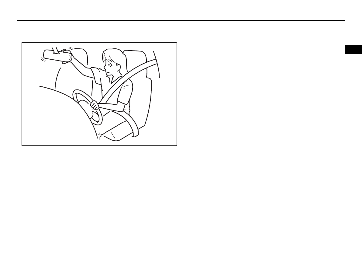
You can adjust the inside rearview mirror
by hand so as to see the rear of your vehicle in the mirror. To adjust the mirror, set
he selector tab (1) to the day position,
t
then move the mirror up, down or sideways
by hand to obtain the best view.
When driving at night, you can move the
selector tab to the night position to reduce
glare from the headlights of vehicles
behind you.
WARNING
• Always adjust the mirror with the
selector set to the day position.
• Only use the night position if it is
necessary to reduce glare from the
headlights of vehicles behind you.
Be aware that in this position you
may not be able to see some
objects that could be seen in the
day position.
CAUTION
• Never spray any liquid directly on
the anti-glare rearview mirror as
this may damage the internal
electronic components.
• Always clean the mirror with a soft
towel. Dampen with clean water
2-20
Page 40

BEFORE DRIVING
Auto dimming rearview mirror (if
equipped)
With HomeLink® Wireless Control System
(1)
You can adjust the auto dimming rearview
mirror by hand so you can see to the rear
of your vehicle in the mirror. This rearview
mirror has a function of automatically
reducing glare from the lights of vehicles
behind you. The function works when the
ignition mode has been changed to “ON”
by pressing the engine switch.
• The mirror is always set to the automatic
dimming mode when the engine switch
is in the “ON” mode.
• When the “ON” switch (2) is pushed, the
green indicator (1) is lit, indicating that
the mirror is set to the automatic dimming mode. To cancel the automatic
dimming mode, push the “OFF” switch
(3); the indicator (1) then goes out.
(2)
(3)
57L21027
• The auto dimming rearview mirror is
automatically deactivated while the gearshift lever is in the “R” position.
(4)
(4)
57L21028
CAUTION
• Do not touch or cover the sensor
(4) since this may impair normal
operation of the system. Blocking
glare from the sensor with an
object such as a shade, sticker,
accessory or baggage may also
impair proper operation of the system.
• Do not hook anything heavy on the
mirror, or the mirror may break
under the weight.
Without HomeLink® Wireless Control
System
(2)(1)
57L30019
You can adjust the auto dimming rearview
mirror by hand so you can see to the rear
of your vehicle in the mirror. This rearview
mirror has a function of automatically
reducing glare from the lights of vehicles
behind you. The function works when the
ignition mode has been changed to “ON”
by pressing the engine switch.
• The mirror is always set to the automatic
dimming mode when the engine switch
is in the “ON” mode.
• When the “AUTO” switch (2) is pushed,
the green indicator (1) is lit, indicating
that the mirror is set to the automatic
dimming mode. To cancel the automatic
dimming mode, push the “AUTO” switch
(2); the indicator (1) then goes out.
2-21
Page 41

BEFORE DRIVING
• The auto dimming rearview mirror is
automatically deactivated while the gearshift lever is in the “R” position.
(3)
(3)
57L30020
CAUTION
• Do not touch or cover the sensor
(3) since this may impair normal
operation of the system. Blocking
glare from the sensor with an
object such as a shade, sticker,
accessory or baggage may also
impair proper operation of the system.
• Do not hook anything heavy on the
mirror, or the mirror may break
under the weight.
Outside Rearview Mirrors
EXAMPLE
79J033
Adjust the outside rearview mirrors so you
can just see the side of your vehicle in the
mirrors.
The passenger’s side mirror is a convex
(curved surface) mirror. Objects seen in
this mirror will look smaller and appear farther away than when seen in a flat mirror.
WARNING
Be careful when judging the size or
distance of a vehicle or other object
seen in the side convex mirror. Be
aware that objects look smaller and
appear farther away than when seen
in a flat mirror.
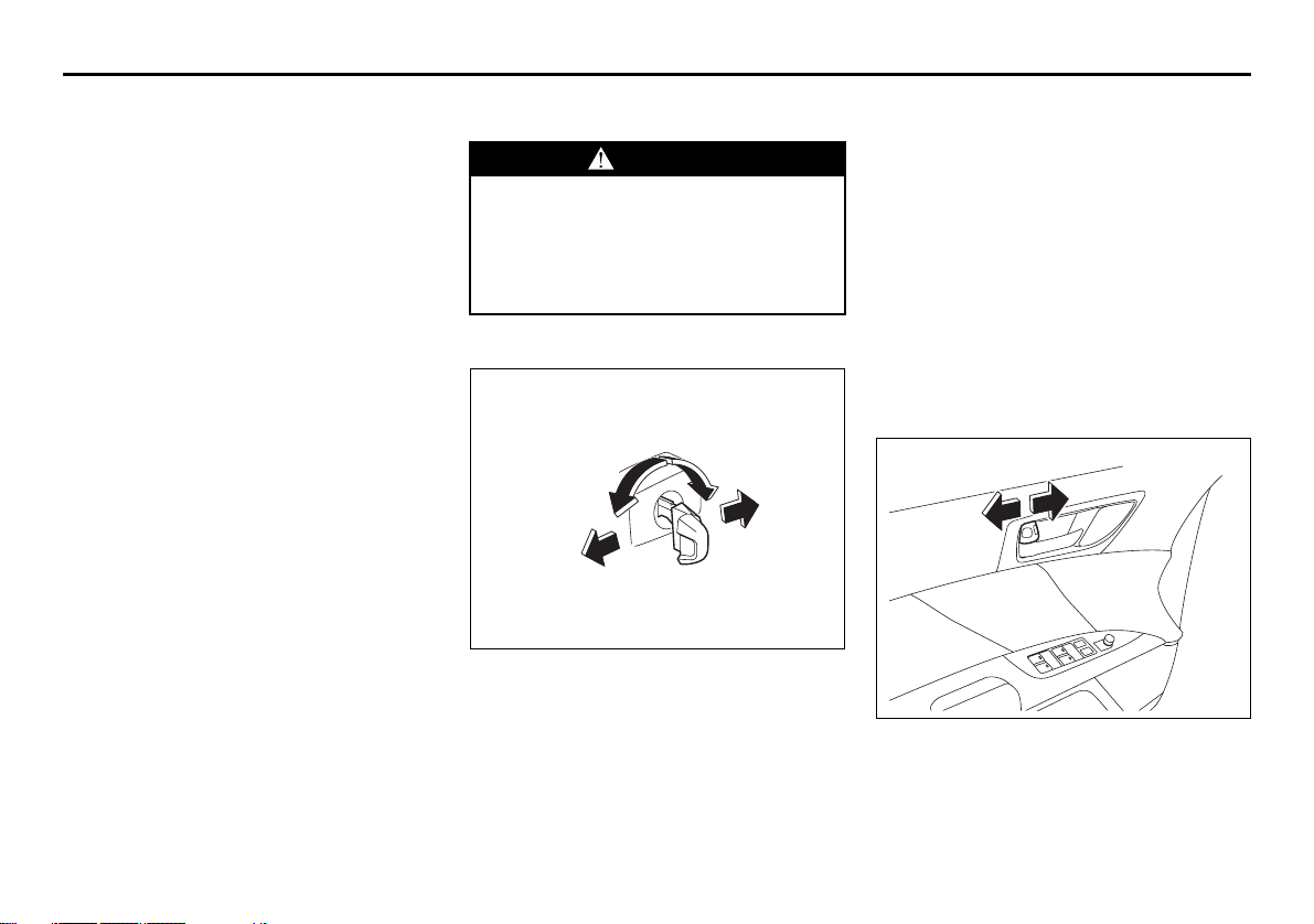
Power Mirror Control
EXAMPLE
(1)
(2)
(3)
(4)
The switch to control the power rearview
mirrors is located on the driver’s door
panel. You can adjust the mirrors after
pressing the engine switch to change the
ignition mode to “ACC” or “ON”. To adjust
the mirrors:
1) Move the selector switch to the left or
right to select the mirror you wish to
adjust.
2) Press the outer part of the switch that
corresponds to the direction you wish to
move the mirror.
3) Return the selector switch to the center
position to help prevent unintended
adjustment.
(1)
(3)(2)
(4)
57L21029
2-22
Page 42

BEFORE DRIVING
NOTE:
If your vehicle is equipped with the heated
outside rearview mirrors, refer to “Heated
Rear Window and Heated Outside Rearview Mirrors (if equipped) Switch” in this
section.
Front Seats
Standard Seat (if equipped)
Adjusting seat position
WARNING
Never attempt to adjust the driver’s
seat or seatback while driving. The
seat or seatback could move unexpectedly, causing loss of control.
Make sure that the driver’s seat and
seatback are properly adjusted
before you start driving.
WARNING
To avoid excessive seat belt slack,
which reduces the effectiveness of
the seat belts as a safety device,
make sure that the seats are adjusted
before the seat belts are fastened.
57L21109
The adjustment lever for each front seat is
located under the front of the seat. To
adjust the seat position, pull up on the
adjustment lever and slide the seat forward
or rearward. After adjustment, try to move
the seat forward and rearward to ensure
that it is securely latched.
2-23
Page 43

BEFORE DRIVING
57L21110
If the driver’s seat is equipped with a seat
height adjuster lever on the outboard side
of the seat, raise or lower the seat by pulling up or down the adjuster lever.
Adjusting seatbacks
WARNING
All seatbacks should always be in an
upright position when driving, or seat
belt effectiveness may be reduced.
Seat belts are designed to offer maximum protection when seatbacks are
in the upright position.
57L21111
To adjust the seatback angle of front seats,
pull up the lever on the outboard side of
the seat, move the seatback to the desired
position, and release the lever to lock the
seatback in place. After adjustment, try
moving the seatback to make sure it is
securely locked.
Power Seat (if equipped)
Adjusting seat position
WARNING
Never attempt to adjust the driver’s
seat or seatback while driving. The
seat or seatback could move unexpectedly, causing loss of control.
Make sure that the driver’s seat and
seatback are properly adjusted
before you start driving.
WARNING
To avoid excessive seat belt slack,
which reduces the effectiveness of
the seat belts as a safety device,
make sure that the seats are adjusted
before the seat belts are fastened.
CAUTION
Do not place any object under the
seat. The object may cause damage
to the seat if caught under it.
2-24
Page 44

BEFORE DRIVING
(1)
(1)
Adjusting seatbacks
WARNING
All seatbacks should always be in an
upright position when driving, or seat
belt effectiveness may be reduced.
Seat belts are designed to offer maximum protection when seatbacks are
in the upright position.
57L21030
Sliding the multi-function control switch (1)
located on the outside of the driver’s seat
forward or backward changes the fore-andaft position of the seat.
2-25
57L21031
• Lifting up the front end of the multi-function control switch causes the front part
of the seat to rise.
• Pushing down the front end of the switch
causes the front part of the seat to lower.
• Lifting up the rear end of the switch
causes the whole seat to rise and the
whole seat to move forward at the same
time.
• Pushing down the rear end of the switch
causes the whole seat to lower and the
whole seat to move backward at the
same time.
(2)
57L21032
Tilt the reclining switch (2) forward or rearward to adjust the angle of the seatback.
Page 45

BEFORE DRIVING
Adjusting the Lumbar Support (if
equipped)
(3)
57L21033
Use the lumbar support switch (3) located
at the rear of the reclining switch to adjust
the force with which the seatback supports
the lumbar area of your back.
• Push the front button on the switch for
firmer support.
• Push the rear button on the switch for
softer support.
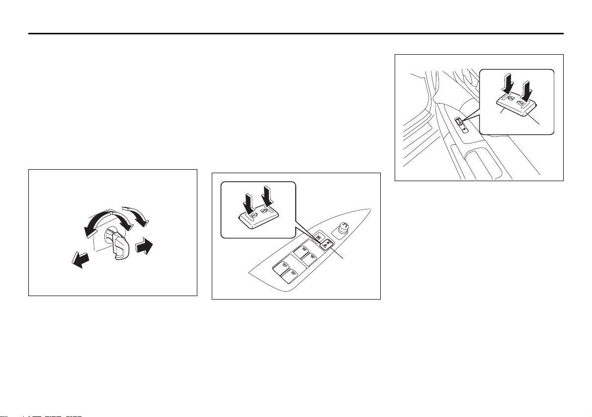
Seat Position Memory System (if
equipped)
Power seat (if equipped)
This function allows you to restore your
preferred preprogrammed seat position at
the touch of one of the three position buttons, which are provided on the top of the
switch block on the outside of the driver’s
seat. One seat position can be programmed to each button, so a total of three
different positions can be stored in memory.
How to program a seat position
(4)
(5)
57L21034
1) Adjust the seat position as desired.
2) Within 5 seconds after pressing the
memory button (4) or while pressing the
button, press one of the position buttons 1 – 3 (5). A buzzer will sound when
the position has been successfully programmed.
NOTE:
The seat position programmed to a position button is overwritten if you program
another seat position to the same button.
How to restore the seat to a memorized
position
1) Press the engine switch to change the
ignition mode to “ACC” or “ON”.
2) Press the desired position button. A
buzzer will sound both when the system
starts and completes the process for
restoring the memorized position. The
seat is now automatically set to the
selected position.
NOTE:
• If you press any of the following buttons
during the process of restoring a memorized position, the system stops the process.
– Memory button
– Position button of any other number
– Any of the seat position adjusting
switches
• Restoring the seat to a memorized posi-
tion is possible only when all of the following conditions are met:
– The ignition mode has been changed
to “ACC” or “ON” by pressing the
engine switch.
– CVT: The gearshift lever is in the “P”
position.
Manual Transaxle: The parking brake
is applied.
– Vehicle speed is 2 mph (3 km/h) or
lower.
2-26
Page 46

BEFORE DRIVING
Head Restraints
80J001
Head restraints are designed to help
reduce the risk of neck injuries in case of
an accident.
Adjust the head restraint to the position
which places the center of the head
restraint closest to the top of your ears. If
this is not possible for very tall passengers,
adjust the head restraint as high as possible.
WARNING
All occupants, including the driver,
should not operate a vehicle or sit in
a vehicle’s seat until the head
restraints are placed in their proper
positions in order to minimize the
risk of severe injury in the event of a
crash.
WARNING
All head restraints must be reinstalled to properly protect vehicle
occupants.
WARNING
• Never drive the vehicle with the
head restraints removed.
• Do not attempt to adjust the head
restraint while driving.
Front
EXAMPLE
57L21035
Each front seat is equipped with a head
restraint.
(1)
(3)
(2)
57L21036
(1) head restraint
(2) bars
(3) release knob
To raise the head restraint, pull upward on
the restraint until it clicks. To lower the
restraint, push down on the restraint while
holding in the release knob (3). If a head
restraint must be removed (for cleaning,
replacement, etc.), push in the release
knob and pull the head restraint all the way
out.
NOTE:
It may be necessary to recline the seatback to provide enough overhead clearance to remove the head restraint.
2-27
Page 47

BEFORE DRIVING
(4)
57L21037
To reinstall the head restraint, insert the
head restraint bars into the holes (4) and
push the head restraint down.
Front Seat Heater
(if equipped)
(2)(1)
57L21038
(1) Driver’s seat heater switch
(2) Passenger’s seat heater switch
With the ignition mode changed to “ON” by
pressing the engine switch, push in one or
both of the seat heater switches to warm
the corresponding seat(s).
• When a seat heater switch is pushed,
the heater inside the corresponding seat
operates.
• Heating intensity can be adjusted to one
of three levels: L (low), M (medium) and
H (high).
• Every time you press the seat heater
switch, the indicators inside the switch
light one at a time in the following
sequence to indicate the selected heater
operation.
– L (low): Weak heating (Only the L indi-
cator lights.)
– M (medium): Moderate heating (The L
and M indicators light.)
– H (high): Strong heating (The L, M and
H indicators light.)
– OFF: Heater turned off (No indicator
illuminates.)
86G064
2-28
Page 48

BEFORE DRIVING
WARNING
Improperly using the seat heater can
be hazardous. An occupant can suffer burns even if the heating temperature is fairly low, if the occupant is
wearing thin pants, a thin skirt or
shorts and leaves the heater on for
long periods.
Avoid using the seat heater for these
occupants:
• People who have reduced feeling in
their legs, including the elderly or
those with certain disabilities.
• Small children, or anyone with sensitive skin.
• People who are asleep or under the
influence of alcohol or other drugs
which make them tired.
CAUTION
To avoid damaging the heater element:
• Do not subject the front seats to
heavy impacts, such as children
jumping on them.
• Do not cover the seat with any
insulating materials such as blankets or cushions.
Rear Seats
Head Restraints
Head restraints are designed to help
reduce the risk of neck injuries in the case
of an accident.
WARNING
All occupants, including the driver,
should not operate a vehicle or sit in
a vehicle’s seat until the head
restraints are placed in their proper
positions in order to minimize the
risk of severe injury in the event of a
crash.
WARNING
All head restraints must be reinstalled to properly protect vehicle
occupants.
WARNING
• Never drive the vehicle with the
head restraints removed.
• Do not attempt to adjust the head
restraint while driving.
NOTE:
It may be necessary to fold forward the
seatback to provide enough overhead
clearance to remove the head restraint.
Adjust the head restraint to the position
which places the center of the head
restraint closest to the top of your ears. If
this is not possible for very tall passengers,
adjust the head restraint as high as possible.
Rear
57L21039
Your vehicle is equipped with three head
restraints on the rear seat.
2-29
Page 49

Left and right seating places
BEFORE DRIVING
57L30058
If the head restraint is tipped forward, raise
it upright.
(1)
(3)
(2)
57L21040
(1) head restraint
(2) bars
(3) release knob
To raise the rear head restraint, pull
upward on the restraint until it clicks. To
lower the restraint, push down on the
restraint while holding in the release knob
(3).
57L30033
When the head restraints must be
removed, use the following methods:
For the left and right seating places, tip the
head restraint forward and then pull it up
while holding the release knob pushed.
NOTE:
You cannot remove the head restraint without tipping it forward; in the upright position, the head restraint touches the cabin
sealing before it can be removed.
WARNING
Never allow anyone to sit on the rear
seat with the head restraints removed
or tipped forward.
2-30
Page 50

BEFORE DRIVING
WARNING
Do not leave the removed head
restraints unfixed in the cabin. They
may hit against you and passengers
in the event of hard braking or other
similar instances, increasing the risk
of an accident.
To reinstall the head restraints, do the following:
For the left and right seating places, insert
the head restraint while still in its forwardtipped position (do not face the backside
forward) into the seatback until it locks.
Then tilt it back to the normal position. The
height of the reinstalled head restraints
must be adjusted properly before use.
WARNING
Always check that the head restraint
is firmly in position after installing it.
Avoid installing it with the backside
facing forward. A wrongly facing
head restraint does not provide the
intended protection, and also its
height cannot be adjusted.
NOTE:
It is recommended to tilt the head
restraints forward to have a better rearward
view.
Central seating place
57L30061
WARNING
Do not allow anyone to sit in the center seating place with the head
restraint removed or in the stowed
position.
When there is a passenger in the central
seating place, pull up the head restraint by
hand and make sure it is securely locked
before starting to drive.
(1)
57L30060
When there is no occupant in the central
seating place, push down the head
restraint fully while holding the release
knob (1) pressed.
When the head restraints must be
removed, use the following methods:
Pull the head restraint up and out of the
seat while holding the release knob
pressed.
WARNING
Do not leave the removed head
restraints unfixed in the cabin. They
may hit against you and passengers
in the event of hard braking or other
similar instances, increasing the risk
of an accident.
2-31
Page 51

BEFORE DRIVING
To reinstall the head restraints, do the following:
With the correct side facing forward, insert
the head restraint into the seat until it is
locked at a height. Then adjust the height
as desired.
WARNING
Always check that the head restraint
is firmly in position after installing it.
Avoid installing it with the backside
facing forward. A wrongly facing
head restraint does not provide the
intended protection, and also its
height cannot be adjusted.
Folding Rear Seats
The rear seats of your vehicle can be folded
forward to provide additional cargo space.
To fold the rear seats forward:
57L30037
1) Stow the seatbelt for the rear center
seat in the retractor behind the head
restraint and retain its end in the holder
so that the seatback for the left seating
place can be folded.
2) Adjust all the head restraints to the lowest positions. In addition, tip forward the
head restraints for the right and left
seats.
3) Detach the seat belts for the right and
left seats from the seatbacks as shown
in the illustration so the belts are not
caught when the seatbacks are moved.
(1)
57L30038
4) Pull the release lever (1) on the top of
each split seat, and fold the seatbacks
forward.
CAUTION
After folding the rear seatback forward, do not allow any foreign material to enter the lock opening. This
may cause damage to the inside of
the lock and prevent the seatback
from being locked securely.
2-32
Page 52

BEFORE DRIVING
WARNING
Luggage or other cargo should be
stowed in the luggage compartment
with the rear seat in an upright position, whenever possible. If you need
to carry cargo in the passenger compartment with the rear seat back
folded forward, be sure to secure the
cargo or it may be thrown about,
causing injury. Never pile cargo
higher than the seatbacks.
To return the seat to the normal position,
follow the procedure below.
WARNING
When returning the rear seatback to
the normal position, be careful that
your finger is not caught between the
lock and the striker.
CAUTION
When returning the rear seatback to
the normal position, make sure that
there is nothing around the striker.
Any foreign materials prevent the
seatback from being locked securely.
(1)
(2)
57L21041
(1) LOCK
(2) UNLOCK
Raise the seatback until it locks into place.
After returning the seat, try moving the
seatback to make sure they are securely
latched.
WARNING
Do not put your hand into the rear
seatback lock opening, or your finger
may get caught and be injured.
CAUTION
After securing the rear seatback,
make sure that it is locked securely. If
it is not, a red sign will appear behind
the release lever.
CAUTION
• When returning the rear seatback
to the normal position, do not allow
any foreign material to enter the
lock opening. This may prevent the
seatback from being locked
securely.
• When returning the rear seatback
to the normal position, be sure to
handle it carefully by hand to avoid
any damage to the lock itself. Do
not push it by using some material
or by applying excessive force.
• As the lock is designed exclusively
for securing the rear seatback, do
not use it for any other purpose.
Incorrect use of it may cause damage to the inside of the lock and
prevent the seatback from being
locked securely.
2-33
Page 53

BEFORE DRIVING
Locking Rear Seatback
(2)
(1)
57L30104
(1) To lock
(2) To unlock
To prevent theft, the rear seatback has a
locking function to prevent it from being
folded down.
• Insert the key into the lock behind the
lock lever, and turn the key clockwise.
• Turn the key counterclockwise to unlock
the seatback.
NOTE:
When a red sign is visible behind the
release lever, the seatback cannot be
locked because it is not completely in the
raised position.
Seat Belts and Child Restraint
Systems
65D231
WARNING
An air bag supplements, or adds to,
the frontal crash protection offered
by seat belts. The driver and all passengers must be properly restrained
by wearing seat belts at all times,
whether or not an air bag is mounted
at their seating position, to minimize
the risk of severe injury or death in
the event of a crash.
Above the pelvis
65D606
WARNING
• Never allow persons to ride in the
cargo area of a vehicle. In the event
of an accident, there is a much
greater risk of injury for persons
who are not riding in a seat with
their seat belt securely fastened.
• Seat belts should always be
adjusted as follows:
– the lap portion of the belt should
be worn low across the pelvis,
not across the waist.
– the shoulder straps should be
worn on the outside shoulder
only, and never under the arm.
– the shoulder straps should be
away from your face and neck,
but not falling off your shoulder.
(Continued)
2-34
Page 54

BEFORE DRIVING
Across the pelvis
WARNING
(Continued)
• Seat belts should never be worn
with the straps twisted and should
be adjusted as tightly as is comfortable to provide the protection
for which they have been designed.
A slack belt will provide less protection than one which is snug.
(Continued)
as low as possible
across the hips
65D201 65D199
WARNING
(Continued)
• Pregnant women should use seat
belts, although specific recommendations about driving should be
made by the woman’s medical advisor. Remember that the lap portion
of the belt should be worn as low
as possible across the hips, as
shown in the diagram.
• Make sure that each seat belt
buckle is inserted into the proper
buckle catch. It is possible to cross
the buckles in the rear seat.
(Continued)
WARNING
(Continued)
• Do not wear your seat belt over
hard or breakable objects in your
pockets or on your clothing. If an
accident occurs, objects such as
glasses, pens, etc. under the seat
belt can cause injury.
• Never use the same seat belt on
more than one occupant and never
attach a seat belt over an infant or
child being held on an occupant’s
lap. Such seat belt use could cause
serious injury in the event of an
accident.
• Periodically inspect seat belt
assemblies for excessive wear and
damage. Seat belts should be
replaced if webbing becomes
frayed, contaminated, or damaged
in any way. It is essential to replace
the entire seat belt assembly after it
has been worn in a severe impact,
even if damage to the assembly is
not obvious.
• Children age 12 and under should
ride properly restrained in the rear
seat, if equipped.
(Continued)
2-35
Page 55

BEFORE DRIVING
WARNING
(Continued)
• Infants and small children should
never be transported unless they
are properly restrained. Restraint
systems for infants and small children can be purchased commercially and should be used. Make
sure that the system you purchase
meets Federal Motor Vehicle Safety
Standards. Read and follow all the
directions provided by the manufacturer.
• Avoid contamination of seat belt
webbing by polishes, oils, chemicals and particularly battery acid.
Cleaning may safely be carried out
using mild soap and water.
• For children, if the shoulder belt
irritates the neck or face, move the
child closer to the center of the
vehicle.
• All seatbacks should always be in
an upright position when driving,
or seat belt effectiveness may be
reduced. Seat belts are designed to
offer maximum protection when
seatbacks are in the upright position.
Lap-Shoulder Belt
Emergency Locking Retractor (ELR)
The seat belt has an emergency locking
retractor (ELR), which is designed to lock
the seat belt only during a sudden stop or
impact. It also may lock if you pull the belt
across your body very quickly. If this happens, let the belt go back to unlock it, then
pull the belt across your body more slowly.
Automatic Locking Retractor (ALR)
The front passenger’s seat belt and the
rear seat belts have emergency locking
retractors (ELRs) that can be temporarily
converted to function as automatic locking
retractors (ALRs). The ALR mode should
be used if you need to secure a child
restraint system in the seat. Refer to the
“Child Restraint Systems” section for
details.
Safety reminder
Sit up straight and
fully back
Low on hips
60A038
Low on hips
60A040
2-36
Page 56

BEFORE DRIVING
To reduce the risk of sliding under the belt
during a collision, position the lap portion
of the belt across your lap as low on your
hips as possible and adjust it to a snug fit
by pulling the shoulder portion of the belt
upward through the latch plate. The length
of the diagonal shoulder strap adjusts itself
to allow freedom of movement.
All Seat Belts Except Rear Center
60A036
To fasten the seat belt, sit up straight and
well back in the seat, pull the latch plate
attached to the seat belt across your body
and press it into the buckle until you hear a
“click”.
60A039
To unfasten the belt, push the red
“PRESS” button on the buckle and allow
the belt to retract.
2-37
Page 57

BEFORE DRIVING
(B)
Rear Center Seat Belt
57L21183
The rear center seat belt is a “Lap-shoulder belt” with a buckle, a latch plate and a
detachable connector. The buckle is
marked as “CENTER” for distinction from
the rear right seat belt buckle. The rear
center seat belt buckle and the connector
are designed so as not to allow a wrong
latch plate to be inserted.
When the rear seatback is in upright position, keep the detachable connector
latched. Only when the rear seatback will
be folded down, unlatch the detachable
connector. To latch and unlatch the connector, see “Unlatching and Latching
Detachable Connector” later in this section.
Fastening
(A)
(B)
(1)
57L21184
Before fastening the rear center belt, make
sure the detachable connector (1) is
securely latched and the webbing is not
twisted.
To fasten the belt, sit up straight and well
back in the seat, pull the latch plate (A)
across your body and press it into the
buckle (B) until you hear a “click”.
Unfastening
57L21185
To unfasten the belt, push the red
“PRESS” button on the buckle (B) and
allow the belt to retract.
2-38
Page 58

BEFORE DRIVING
57L30107
57L21108
WARNING
To minimize risk of severe injury or
death in the event of a crash, always
wear seat belt with both latches buckled.
Unlatching and Latching
Detachable Connector
Unlatching
(D)
57L21186
To unlatch the connector:
1) Insert the key into the slot on the connector (D) and allow the belt to retract.
2) Once the belt has completely retracted,
stow the belt in the holder. Refer to
“Stowing Rear Center Lap-Shoulder
Belt” for details later in this section.
CAUTION
When the rear seatback is folded forward, be sure to unlatch the connector of rear center belt. Otherwise, the
seat belt webbing can be damaged.
2-39
Page 59

BEFORE DRIVING
Latching
To latch the connector:
1) Pull the belt out from the holder.
(C)
(D)
57L21187
2) Insert the connector latch plate (C) into
the connector (D) so as to align the triangle marks until you hear a “click”.
WARNING
Make sure the detachable connector
is securely latched and the webbing
is not twisted.
Stowing Rear Center Lap-Shoulder
Belt
Be sure to stow the belt after the belt is
retracted completely.
(A)
57L21188
To stow the belt, insert the latch plate (A)
into the slot of the holder. To pull the belt
out, simply pull the latch plate.
WARNING
Stow the belt end properly, or the belt
end may hit passengers in case of
vehicle bumps.
Seat Belt Reminder
Driver’s seat belt reminder light
EXAMPLE
57L21042
Front passenger’s seat belt reminder
light (if equipped)
57L21043
2-40
Page 60

BEFORE DRIVING
When the driver and front passenger don’t
buckle their seat belts, the driver’s seat belt
reminder light in the instrument cluster and
the front passenger’s seat belt reminder
light in the information display will come on
and a buzzer will sound as a reminder to
the driver and front passenger to buckle
their seat belts.
WARNING
It is absolutely essential that the
driver and passengers wear their seat
belts at all times. Persons who are
not wearing seat belts have a much
greater risk of injury if an accident
occurs. Make a regular habit of buckling your seat belt before starting the
engine.
The seat belt reminder functions as shown
in the figure below. There are some differences between the driver’s seat belt
reminder and the front passenger’s seat
belt reminder. For more details, refer to the
following explanation.
2-41
Page 61

BEFORE DRIVING
Flow chart
Engine Switch “ON”
Seat belt is
buckled
Vehicle speed:
below 8 km/h
No reminder
Seat belt is
unbuckled
Vehicle speed:
over 8 km/h
57L21044
Vehicle speed:
below 8 km/h
Vehicle speed:
increase to 8 km/h
Seat belt is
unbuckled
Reminder 1
30 sec.
Vehicle speed:
over 8 km/h
Reminder 2
3 min.
Reminder 3
No reminder
Reminder 1 – 3
For each reminder 1 – 3, the reminder light comes on for about 20 seconds, then blinks for
about 55 seconds. When the reminder light first comes on, a buzzer sounds intermittently
for about 6 seconds.
Driver’s seat belt reminder
If the driver’s seat belt remains unbuckled
after changing the ignition mode to “ON” by
pressing the engine switch, the driver’s
seat belt reminder works as follows:
1) The driver’s seat belt reminder light will
come on for about 20 seconds when
the ignition mode is changed to “ON”
by pressing the engine switch, the
engine switch then will blink for about
55 seconds. When the light comes on,
a buzzer will also sound intermittently
for about 6 seconds (Reminder 1).
2) If the vehicle is driven (vehicle speed >
8 km/h), Reminder 2 will operate about
30 seconds after Reminder 1 has finished.
If the vehicle is not driven (vehicle
speed < 8 km/h), Reminder 2 will operate when driving starts (vehicle speed >
8 km/h).
3) Reminder 3 will operate about 3 minutes after Reminder 2 has finished.
4) Even if the driver’s seat belt remains
unbuckled after Reminder 3, there will
be no further reminders.
If the driver has buckled his or her seat belt
and later unbuckles the seat belt, the
reminder system will be activated from
Reminder 1 or Reminder 2 according to
the vehicle speed. (Refer to the flow chart.)
The driver’s seat belt reminder will be automatically canceled when the driver’s seat
belt is buckled or the ignition mode is
2-42
Page 62

BEFORE DRIVING
changed to “LOCK” (OFF) by pressing the
engine switch.
Front passenger’s seat belt reminder (if
equipped)
The front passenger’s seat belt reminder
will activate only when there is a passenger sitting in the front seat. In some situations, however, such as when you place
heavy objects in the front seat, the seat
belt reminder can be activated as if there
were a passenger present. The front passenger’s seat belt reminder works in the
same manner as the driver’s seat belt
reminder, except that it is not activated
until 10 seconds after the ignition mode is
changed to “ON” by pressing the engine
switch.
Shoulder Anchor Height Adjuster
EXAMPLE EXAMPLE
57L21045
Adjust the shoulder anchor height so that
the shoulder belt rides on the center of the
outside shoulder. To upward, slide the
anchor up. To downward, slide the anchor
down while down the lock lever. After
adjustment, make sure that the anchor is
securely locked.
WARNING
Be sure that the shoulder belt is positioned on the center of the outside
shoulder. The belt should be away
from your face and neck, but not falling off your shoulder. Misadjustment
of the belt could reduce the effectiveness of the safety belt in a crash.
Seat Belt Inspection
65D209S
Periodically inspect the seat belts to make
sure they work properly and are not damaged. Check the webbing, buckles, latch
plates, retractors, anchorages and guide
loops. Replace any seat belts which do not
work properly or are damaged.
2-43
Page 63

BEFORE DRIVING
WARNING
Be sure to inspect all seat belt
assemblies after any collision. Any
seat belt assembly which was in use
during a collision (other than a very
minor one) should be replaced, even
if damage to the assembly is not
obvious. Any seat belt assembly
which was not in use during a collision should be replaced if it does not
function properly, it is damaged in
any way or the seat belt pretensioners were activated.
Child Restraint Systems
Infant restraint - rear seat only
EXAMPLE
60G332
65D202
Infant restraint - rear seat only
EXAMPLE
80JC007
Booster seat
EXAMPLE
80JC008
2-44
Page 64

BEFORE DRIVING
SUZUKI highly recommends that you use
a child restraint system to restrain infants
and small children. Many different types of
child restraint systems are available; make
sure that the restraint system you select
meets Federal Motor Vehicle Safety Standards.
All child restraint systems are designed to
be secured in vehicle seats by either seat
belts (lap belts or the lap portion of lapshoulder belts) or by special rigid lower
anchor bars built into the seats. Whenever
possible, SUZUKI recommends that child
restraint systems be installed on the rear
seat. According to accident statistics, children are safer when properly restrained in
rear seating positions than in front seating
positions.
If you must use a front-facing child restraint
in the front passenger’s seat, be sure to
move the front passenger’s seat as far
back as possible.
65D607 65D608
WARNING
Do not install a rear-facing child
restraint in the front passenger’s
seat. If the passenger’s air bag
inflates, a child in a rear-facing child
restraint could be killed or seriously
injured. The back of a rear-facing
child restraint would be too close to
the inflating air bag.
2-45
65D609
Page 65

BEFORE DRIVING
WARNING
Children could be endangered in a
crash if their child restraints are not
properly secured in the vehicle.
When installing a child restraint system, be sure to follow the instructions below. Be sure to secure the
child in the restraint system according to the manufacturer’s instructions.
WARNING
In an accident or sudden stop, the
rear seat armrest (if equipped) could
fall forward. If there is a child in a
rear-facing child restraint in the center seating position, the falling armrest could injure the child. Make sure
the armrest is back in the seat and
locked when not in use.
Installation with Lap-Shoulder Seat
Belts (child restraint with no top
strap)
A-ELR type belt
EXAMPLE
83E031
Install your child restraint system according to the instructions provided by the child
restraint system manufacturer. If you install
the child restraint system in the front seat,
be sure to slide the seat to the rearmost
position. After making sure that the seat
belt is securely latched:
(1)
57L31032
1) If you install the child restraint system in
the rear right or left seat, remove the
head restraint (1) or raise the head
restraint upright and make it lock at the
highest position.
2-46
Page 66

BEFORE DRIVING
A-ELR type belt
A-ELR type belt
EXAMPLE EXAMPLE
83E035
2) Pull all of the remaining webbing out of
the retractor. You will hear a click, which
means that the emergency locking
retractor (ELR) has converted to function as an automatic locking retractor
(ALR).
3) Allow the extra webbing to retract, and
pull the webbing toward the retractor to
take up any slack. Make sure that the
lap portion of the belt is tight around the
child restraint system and the shoulder
portion of the belt is positioned so that it
cannot interfere with the child’s head or
neck.
83E032
A-ELR type belt
EXAMPLE
83E036
4) Make sure that the retractor has converted to the ALR mode by trying to pull
webbing out of the retractor. If the
retractor is in the ALR mode, the belt
will be locked.
WARNING
If the retractor is not in the ALR
mode, the child restraint system can
move or tip over when your vehicle
turns or stops abruptly.
2-47
Page 67

BEFORE DRIVING
WARNING
Before installing a child restraint in
the rear center seat, follow these
steps for secure installation:
• Make sure the detachable connector is securely latched and the webbing is not twisted.
• Make sure the seat belt is passed
through the seat belt guide.
A-ELR type belt
EXAMPLE
Move to check
A-ELR type belt
EXAMPLE
Pull to tighten
65D234
To revert from ALR to ELR
EXAMPLE
65D267
When you unbuckle the seat belt and allow
it to retract to a certain length, the retractor
will automatically revert back to the normal
ELR mode.
65D235
5) Try moving the child restraint system in
all directions, to make sure it is securely
installed. If you need to tighten the belt,
pull more webbing toward the retractor.
2-48
Page 68

BEFORE DRIVING
Installation with the LATCH System
Rigid lower connecting
bar type
2-49
Flexible lower connecting
strap type
65D337
EXAMPLE EXAMPLE
57L21046
Your vehicle is equipped with lower
anchors for securing up to one or two standard LATCH-type child restraint(s) in the
rear seats. (LATCH stands for Lower
Anchors and Tethers for Children.)
The anchors are located where the rear of
the seat cushion meets the bottom of the
seatback.
The covers marked with the child restraint
symbol as shown in the illustration indicate
the presence of lower anchors. Remove
the covers before installing the child
restraint system. Cover the lower anchors
when not in use.
NOTE:
Stow the removed covers in the glove box
or other appropriate stowage so they will
not inconvenience the occupants.
Install the LATCH-type child restraint system according to the instructions provided
by the child restraint system manufacturer.
After installing, try moving the child
restraint system in all directions, especially
forward to make sure the flexible straps or
rigid connecting bars are securely latched
to the anchors.
57L21047
Page 69

NOTE:
Although there are three rear seating positions, you cannot install three LATCH type
child restraints in the rear seats. You can
install one or two LATCH restraint(s). Be
sure to install the LATCH type child
restraint(s) in the outboard seating positions.
If your LATCH restraint has flexible lower
connecting straps, these general instructions apply:
1) If possible, fold the seatback rearward
for easier installation.
EXAMPLE
73K017
2) Place the child restraint in the rear seat,
feeding the strap hooks through the
slots in the seat cushion or the slots in
the seatback bottom.
EXAMPLE
65D340
3) Snap the strap hooks to the anchors.
Take care not to pinch your fingers.
BEFORE DRIVING
EXAMPLE
65D341
4) Return the seatback to the normal,
upright position. Tighten the lower
straps as described in the child restraint
owner’s manual. Attach the top tether
strap, if applicable.
2-50
Page 70

BEFORE DRIVING
EXAMPLE
If your LATCH restraint has rigid lower connecting bars, these general instructions
apply:
1) If possible, fold the seatback rearward
for easier installation.
EXAMPLE
EXAMPLE
65D342
5) Make sure the child restraint is securely
fastened by trying to move the child
restraint system in all directions, especially forward.
WARNING
The seatback should always be
securely latched in a fairly upright
position when any type of child seat
is installed. An unlatched or reclined
seatback will reduce the intended
effectiveness of the child restraint
system.
2-51
54G183
3) Use your hands to carefully align the
connecting bar tips with the anchors.
Take care not to pinch your fingers.
78F114
2) Place the child restraint in the rear seat,
inserting the connecting bars through
the slots in the seat cushion or the slots
in the seatback bottom.
Page 71

EXAMPLE
EXAMPLE
BEFORE DRIVING
Installation of Child Restraint with
Top Strap
54G184
4) Push the child restraint toward the
anchors so that the connecting bar tips
are partially hooked to the anchors.
Use your hands to confirm the position.
54G185
5) Grasp the front of the child restraint and
push the child restraint forcefully to
latch the connecting bars. Make sure
they are securely latched by trying to
move the child restraint system in all
directions, especially forward.
6) Return the seatback if folded. Attach
the top tether strap, if applicable.
WARNING
The seatback should always be
securely latched in a fairly upright
position when any type of child seat
is installed. An unlatched or reclined
seatback will reduce the intended
effectiveness of the child restraint
system.
57L21048
Some child restraint systems require the
use of a top strap. Top strap anchor brackets are provided in your vehicle at the locations shown in the illustrations. Install the
child restraint system as follows:
1) Secure the child restraint on the rear
seat using the procedure described
above for securing a restraint system
that does not require a top strap.
2) Open the cover that is marked with the
anchor bracket symbol to access the
anchor bracket. Close the cover when
not using the anchor bracket.
3) Hook the top strap to the anchor
bracket and tighten the top strap
according to the instructions provided
by the child restraint system manufacturer. Be sure to attach the top strap to
the corresponding anchor located
2-52
Page 72

BEFORE DRIVING
directly behind the child restraint. Do
not attach the top strap to the luggage
restraint loops (if equipped).
WARNING
Do not attach the child restraint top
strap to the luggage restraint loops
(if equipped). Incorrectly attached top
strap will reduce the intended effectiveness of the child restraint system.
Typ e 1
Typ e 2
57L21049
4) When routing the top strap, be sure to
pass the top strap as shown in the illustration. (Refer to “Adjustable Head
Restraints” section for details on how to
raise or lower the head restraint.)
5) Make sure that cargo does not interfere
with routing of the top strap.
Seat Belt Extender
65D613
(1) Center of body
(2) Less than 152 mm (6 inches)
(3) Open end of extender buckle
If a seat belt cannot be fastened securely
because it is not long enough, see an
authorized SUZUKI dealer for a seat belt
extender. Seat belt extenders are available
for each seating position except for the
rear center position. After inspecting the
relationship between the seat belt length,
the occupant’s body size, and the seat
adjustment (the driver’s seat should always
be adjusted as far back as possible while
still maintaining control of the vehicle, and
other adjustable seats should be adjusted
as far back as possible), your dealer can
select the appropriate seat belt extender.
2-53
Page 73

• A seat belt extender should only be used
for the person, vehicle and seating location it was provided for.
• When using the extender, ensure that
both ends are latched securely. Do not
use the extender if the open end of the
extender’s buckle is within 152 mm (6
inches) of the center of the occupant’s
body (See diagram). Use of the extender
when the buckle is too close to the center of the body could increase the risk of
abdominal injury in the event of an accident, and could cause the shoulder belt
to be positioned incorrectly.
• Make sure to use the correct buckle corresponding to your seating position.
• Seat belt extenders are not intended for
use by pregnant women, and should
only be used upon approval by their
medical advisors.
• Remove and stow the extender when it
is not being used.
WARNING
Failure to follow these instructions
may increase the risk of injury in a
crash.
• Only use an extender for the person, vehicle and seating position it
was provided for.
• Do not use if open end of
extender’s buckle is within 152 mm
(6 inches) of center of occupant’s
body (See diagram).
• Remove and stow the extender
when it is not being used.
Seat Belt Pretensioner System
(for front seat belt only)
EXAMPLE
57L21125
BEFORE DRIVING
WARNING
This section of the owner’s manual
describes your SUZUKI’s SEAT BELT
PRETENSIONER SYSTEM. Please
read and follow ALL these instructions carefully to minimize your risk
of severe injury or death.
Your vehicle is equipped with a seat belt
pretensioner system at the front seating
positions. You can use the pretensioner
seat belts in the same manner as ordinary
seat belts.
The seat belt pretensioner system works
with the SUPPLEMENTAL RESTRAINT
SYSTEM (advanced air bags). The crash
sensors and the electronic controller of the
air bag system also control the seat belt
pretensioners. The pretensioners are triggered only when there is a frontal or side
crash severe enough to trigger the air bags
and the seat belts are fastened. If the seat
belts are not fastened, the respective pretensioner system will not be activated. For
precautions and general information
including servicing the pretensioner system, refer to the “Supplemental Restraint
System (air bags)” section in addition to
this “Seat Belt Pretensioner System” section, and follow all those precautions.
2-54
Page 74

BEFORE DRIVING
The front seat belt retractors and lap belt
anchorages are each provided with a pretensioner. The pretensioner tightens the
seat belt so the belt fits the occupant’s
body more snugly in the event of a frontal
or side crash. The retractors will remain
locked after the pretensioners are activated. Upon activation, some noise will
occur and some smoke may be released.
These conditions are not harmful and do
not indicate a fire in the vehicle.
The driver and all passengers must be
properly restrained by wearing seat belts
at all times, whether or not a pretensioner
is equipped at their seating position, to
help minimize the risk of severe injury or
death in the event of a crash.
Sit fully back in the seat; sit up straight; do
not lean forward or sideways. Adjust the
belt so the lap portion of the belt is worn
low across the pelvis, not across the waist.
Please refer to the “Seat Adjustment” section and the instructions and precautions
about the seat belts in this “Seat Belts and
Child Restraint Systems” section for details
on proper seat and seat belt adjustments.
Please note that the pretensioners along
with the air bags will activate only in severe
frontal or side collisions. They are not
designed to activate in rear impacts, rollovers or minor frontal collisions. The pretensioners can be activated only once. If
the pretensioners are activated (that is, if
the air bags are activated), have the pre-
tensioner system serviced by an authorized SUZUKI dealer as soon as possible.
If the AIR BAG light on the instrument cluster does not blink or come on briefly when
the ignition mode is changed to “ON” by
pressing the engine switch, stays on for
more than 10 seconds, or comes on while
driving, the pretensioner system or the air
bag system may not work properly. Have
both systems inspected by an authorized
SUZUKI dealer as soon as possible.
Service on or around the pretensioner system components or wiring must be performed only by an authorized SUZUKI
dealer who is specially trained. Improper
service could result in unintended activation of pretensioners or could render the
pretensioner inoperative. Either of these
two conditions may result in personal
injury.
To prevent damage or unintended activation of the pretensioners, be sure the battery is disconnected and the engine switch
has been in the “LOCK” (OFF) mode for at
least 90 seconds before performing any
electrical service work on your SUZUKI.
Do not touch pretensioner system components or wiring. The wires are wrapped
with yellow tape or yellow tubing, and the
couplers are yellow. When scrapping your
SUZUKI, ask an authorized SUZUKI
dealer, body repair shop or scrap yard for
assistance.
Supplemental Restraint
System (air bags)
EXAMPLE
54G022
WARNING
This section of the owner’s manual
describes the protection provided by
your SUZUKI’s SUPPLEMENTAL
RESTRAINT SYSTEM (air bags).
Please read and follow ALL these
instructions carefully to minimize
your risk of severe injury or death in
the event of a collision.
Your vehicle has advanced front air bags
and front side air bags for the driver and
right front passenger. Your vehicle also has
side curtain air bags and rear side air
bags.
2-55
Page 75

BEFORE DRIVING
EXAMPLE
8
8
7
1
2
11
10
6
9
4
3
14
57L21051
Your vehicle is equipped with a Supple-
15
mental Restraint System consisting of the
following components in addition to a lap-
11
4
9
3
5
12
13
12
shoulder belt at each front seating position.
1. Driver’s front air bag
2. Front passenger’s front air bag
3. Seat belt pretensioners
4. Lap outer pretensioners
5. Air bag controller
6. Occupant classification module
7. “PASS AIR BAG OFF” indicator
57L21050
8. Forward crash sensors
9. Front side air bags
10.Side curtain air bags
11.Side crash sensors
12.Rear side air bags
13.Rear side crash sensors
14.Front passenger’s sensor mat
15.Seat belt buckle sensors
2-56
Page 76

BEFORE DRIVING
63J030
If the AIR BAG light on the instrument cluster does not blink or come on when the
ignition mode is first changed to “ON” by
pressing the engine switch, or the AIR
BAG light stays on, or comes on while driving, the air bag system (or the seat belt
pretensioner system) may not work properly. Have the air bag system inspected by
an authorized SUZUKI dealer as soon as
possible.
Front Air Bags
EXAMPLE
80JS026
EXAMPLE
57L21116
The driver’s front air bag is located behind
the center pad of the steering wheel and
the front passenger’s front air bag is
located behind the passenger’s side of the
dashboard. The words “SRS AIRBAG” are
molded into the air bag covers to identify
the location of the air bags.
2-57
EXAMPLE
57L21115
Page 77

BEFORE DRIVING
Frontal collision range
60G032
Front air bags are designed to inflate only
in severe frontal collisions.
Front air bags will not inflate
65D236
Front air bags will probably not inflate
65D237
Front air bags are not designed to inflate in
rear impacts, side impacts, rollovers or
minor frontal collisions, since they would
offer no protection in those types of accidents. Remember, since air bags deploy
only one time during an accident, seat
belts are needed to restrain occupants
from further movements during the accident.
Therefore, an air bag is NOT a substitute
for seat belts. To maximize your protection,
ALWAYS WEAR YOUR SEAT BELTS. Be
aware that no system can prevent all possible injuries that may occur in an accident.
WARNING
An air bag supplements, or adds to,
the crash protection offered by seat
belts. The driver and all passengers
must be properly restrained by wearing seat belts at all times, whether or
not air bags are mounted at their
seating position, to minimize the risk
of severe injury or death in the event
of a crash.
Your vehicle has “dual stage” front air
bags, which adjust the air bag inflation
force according to crash severity. Also,
your vehicle has a front passenger sensing
system, which turns off the front passenger’s front air bag and seat belt pretensioner under certain conditions.
2-58
Page 78

BEFORE DRIVING
Front Side Air Bags, Rear Side Air
Bags and Side Curtain Air Bags
EXAMPLE
EXAMPLE
2-59
57L21052
57L21053
Front side air bags are located in the part
of the front seatbacks closest to the doors.
The words “SRS AIRBAG” are indicated on
the tag to identify the location of the front
side air bags.
57L21054
The rear side air bags are stowed in the
covers at both door-side ends of the rear
seatback. The words “SRS AIRBAG” are
molded into each of the seatback ends.
Page 79

BEFORE DRIVING
EXAMPLE
80JM146
Side curtain air bags are located in the roof
lining. The words “SRS AIRBAG” are
molded into the pillar to identify the location of the side curtain air bags.
Side collision range
80JM032
Front side air bags, rear side air bags and
side curtain air bags are designed to inflate
only in severe side impact collisions.
Front side air bags, rear side air bags
and side curtain air bags will not inflate
54G027
2-60
Page 80

BEFORE DRIVING
Front side air bags, rear side air bags
and side curtain air bags will probably
not inflate
57L21126
Front side air bags, rear side air bags and
side curtain air bags are not designed to
inflate in frontal or rear collisions, rollovers
or minor side collisions, since they would
offer no protection in those types of accidents. Only the front side air bag, rear side
air bag and side curtain air bag on the side
of the vehicle that is struck will inflate.
However, in a frontal angle collision, the
right and left front side air bags, rear side
air bags and side curtain airbags may
inflate. Remember, since an air bag
deploys only one time during an accident,
seat belts are needed to restrain occupants from further movements during the
accident.
Therefore, an air bag is NOT a substitute
for seat belts. To maximize your protection,
ALWAYS WEAR YOUR SEAT BELTS. Be
aware that no system can prevent all possible injuries that may occur in an accident.
WARNING
An air bag supplements, or adds to,
the crash protection offered by seat
belts. The driver and all passengers
must be properly restrained by wearing seat belts at all times, whether or
not air bags are mounted at their
seating position, to minimize the risk
of severe injury or death in the event
of a crash.
WARNING
If the AIR BAG light in the instrument
cluster ever comes on and stays on,
it means that something may be
wrong with the air bag system. If this
ever happens, have the vehicle serviced immediately, because the air
bags may not offer the protection for
which they were designed.
Front Passenger’s Seat Belt Buckle
Sensor
The front passenger’s seat belt buckle is
equipped with a sensor to monitor whether
or not the front passenger’s seat belt is fastened.
WARNING
When the buckle sensor has a problem, the AIR BAG light on the instrument cluster will turn on. If this
happens, deployment of the front
passenger’s air bag will not include
consideration of whether the front
passenger’s seat belt is fastened or
not. Have the air bag system
inspected by an authorized SUZUKI
dealer as soon as possible.
2-61
Page 81

BEFORE DRIVING
Front Passenger Sensing System
The front passenger sensing system will
turn off the front passenger’s front air bag
and seat belt pretensioner under certain
conditions. This system works using a sensor mat that is part of the front passenger’s
seat. The front passenger sensing system
is designed to detect whether an occupant
is present in the seat and, if an occupant is
present, to determine whether the front
passenger’s front air bag and seat belt pretensioner should be enabled or disabled
(turned off).
NOTE:
The front passenger’s side air bag and the
side curtain air bag are not controlled by
the front passenger sensing system.
PASSENGER
AIRBAG OFF
PASSENGER
AIRBAG OFF
57L21055
When you press the engine switch to
change the ignition mode to “ON”, the
“PASS AIR BAG OFF” indicator comes on
for several seconds to let you know the
system is working. When the front passenger sensing system has turned off the front
passenger’s front air bag including the seat
belt pretensioner, the “PASS AIR BAG
OFF” indicator will come on and stay on to
remind you that the front passenger’s front
air bag is off.
The front passenger sensing system uses
front seat pressure measurements and
pressure locations to determine whether to
activate or deactivate the front passenger’s
front air bag. The front passenger sensing
system may or may not turn off the front air
bag, depending on the front passenger’s
seating posture and body build. The air
bag should be turned off in the following
situations:
• There is no occupant in the front passenger seat.
• The occupant of the front passenger
seat lifts his or her weight off of the seat
for a period of time.
• The occupant of the front passenger
seat is an infant or small child in a child
restraint system or a small child in a
booster seat.
• A smaller person, such as a child who
has outgrown child restraints or a very
small adolescent is seated in the front
passenger seat.
NOTE:
If the front passenger seat is unoccupied,
the “PASS AIR BAG OFF” indicator will not
come on but the front passenger’s front air
bag will not deploy and the seat belt pretensioner will not operate.
If you have secured a child in the front passenger seat in a forward-facing child
restraint system or booster seat and the
“PASS AIR BAG OFF” indicator light is not
on, turn the vehicle off, remove the child
restraint or booster seat from the vehicle
and reinstall it following the child restraint
or booster seat manufacturer’s directions.
Also refer to “Seat Belts and Child
Restraint Systems” in this section. If, after
reinstalling the child restraint and restarting the vehicle, the “PASS AIR BAG OFF”
indicator is still not lit, check to make sure
that the vehicle’s seatback is not pressing
the child restraint into the seat cushion. If
this happens, slightly recline the vehicle’s
seatback and adjust the seat cushion if
possible. Also make sure the child restraint
is not trapped under the vehicle head
restraint. If this happens, adjust the head
restraint. If the “PASS AIR BAG OFF” indicator is still not on, secure the child in the
child restraint or booster seat in a rear seat
position in the vehicle and check with your
dealer.
2-62
Page 82

BEFORE DRIVING
65D607
WARNING
Do not install a rear-facing child
restraint in the front passenger’s
seat. If the passenger’s front air bag
inflates, a child in a rear-facing child
restraint could be seriously injured.
The back of a rear-facing child
restraint would be too close to the
inflating air bag.
According to accident statistics, children
are safer when properly restrained in rear
seating positions than in front seating positions. Whenever possible, SUZUKI recommends you install child restraints in the
rear seat.
The front passenger sensing system is
designed to enable the front passenger’s
front air bag when the system senses a
properly-seated adult in the front passenger’s seat. When the passenger sensing
system has allowed the air bag to be
enabled, the “PASS AIR BAG OFF” indicator will remain off to remind you that the air
bag is active.
If a person of adult size is sitting in the
front passenger’s seat and the “PASS AIR
BAG OFF” indicator comes on, it could be
because that person isn’t sitting properly in
the seat. If this happens, unfasten the seat
belts, sit upright in the center of the seat
with the seatback nearly vertical and your
legs outstretched, and refasten the seat
belt.
52D258
When seated as shown in the above illustration, the front passenger sensing system senses a properly-seated occupant
and enables the air bag.
When using a seat belt extender, follow the
instructions in the “Seat Belt Extender”
section.
WARNING
Do not place any heavy objects on
the front passenger’s seat. The pressure sensors in the sensor mat could
be damaged and the front passenger
sensing system may not work properly.
2-63
Page 83

WARNING
The front passenger sensing system
may not work properly in the following situations:
• The occupant is sitting near the
dashboard or is not sitting in the
proper position.
• Objects placed under the seat are
pushing up on the seat cushion.
WARNING
If the “PASS AIR BAG OFF” indicator
on the instrument panel turns on
even though there is no occupant or
an adult occupant in the front passenger’s seat, it means that something may be wrong with the
passenger sensing system. Have the
system inspected by an authorized
SUZUKI dealer as soon as possible.
WARNING
• Do not spill any liquids on the seat.
Liquids can damage the sensors
under the front seat.
• Have the front passenger’s sensor
mat inspected by your dealer after
a collision.
• Do not replace the front seats. If
you replace them, the air bags and
front passenger sensing system
may not work properly.
• Do not use a seat cover. If you use
a seat cover, the front passenger
sensing system may not work properly.
BEFORE DRIVING
How the System Works
In a frontal collision, the crash sensors will
detect rapid deceleration and send a signal
to the controller. If the controller judges
that the deceleration represents a severe
frontal crash, the controller will trigger the
inflators. The controller also judges:
• Whether the front air bags should deploy
at reduced power or at full power according to crash severity.
• Whether the air bags should deploy at
reduced power or at full power according
to crash severity.
• Whether the front passenger’s front air
bag should deploy or not based on classification of the occupant of the front
passenger’s seat.
Since your vehicle is equipped with front
side air bags, rear side air bags and side
curtain air bags, crash sensors will detect
a side collision, and if the controller judges
that the side collision is severe enough, it
will trigger the front side air bag, rear side
air bags and side curtain air bag inflators.
The inflators inflate the appropriate air
bags with nitrogen or argon gas. The
inflated air bags provide a cushion for your
head (front air bags and side curtain air
bags only) and upper body. The air bag
inflates and deflates so quickly that you
may not even realize that it has activated.
The air bag will neither hinder your view
nor make it harder to exit the vehicle.
2-64
Page 84

BEFORE DRIVING
Air bags must inflate quickly and forcefully
in order to reduce the chance of serious or
fatal injuries. However, an unavoidable
consequence of the quick inflation is that
the air bag may irritate bare skin, such as
the facial area against a front air bag. Also,
upon inflation, a loud noise will occur and
some powder and smoke will be released.
These conditions are not harmful and do
not indicate a fire in the car. Be aware,
however, that some air bag components
may be hot for a while after inflation.
A seat belt helps keep you in the proper
position for maximum protection when an
air bag inflates. Adjust your seat as far
back as possible while still maintaining
control of the vehicle. Sit fully back in your
seat; sit up straight; do not lean over the
steering wheel or dashboard. Front occupants should not lean on or sleep against
the door. Please refer to the “Seat Adjustment” section and the “Seat Belts and
Child Restraint Systems” section in the
“BEFORE DRIVING” section for details on
proper seat and seat belt adjustments.
65D610
54G582
WARNING
• The driver should not lean over the
steering wheel. The front passenger should not rest his or her body
against the dashboard, or otherwise get too close to the dashboard. For vehicles with side air
bags, rear side air bags and side
curtain air bags, occupants should
not lean on or sleep against the
door. In these situations, the out-ofposition occupant would be too
close to an inflating air bag, and
may suffer severe injury.
• Do not attach any objects to, or
place any objects over, the steering
wheel or dashboard. Do not place
any objects between the air bag
and the driver or front passenger.
These objects may interfere with air
bag operation or may be propelled
by the air bag in the event of a
crash. Either of these conditions
may cause severe injury.
• For vehicles with front side air
bags, do not place seat covers on
the front seats, because seat covers could restrict the air bag’s inflation. Also, do not place any cup
holders or other objects on the
door, as these objects could be
propelled by the air bag in the event
of a crash. Either of these conditions may cause severe injury.
2-65
Page 85

BEFORE DRIVING
Note that even though your vehicle may be
moderately damaged in a collision, the collision may not have been severe enough to
trigger the front, side, rear side, or side
curtain air bags to inflate. If your car sustains ANY front-end or side damage, have
the air bag system inspected by an authorized SUZUKI dealer to ensure it is in
proper working order.
Your vehicle is equipped with a diagnostic
module which records information about
the air bag system if the air bags deploy in
a crash. The module records information
about overall system status, which sensors
activated the deployment, and whether the
front seat belts were in use.
Servicing the Air Bag System
If the air bags inflate, have the air bags and
related components replaced by an authorized SUZUKI dealer as soon as possible.
If your vehicle ever gets in deep water and
the driver’s floor is submerged, the air bag
controller could be damaged. If this happens, have the air bag system inspected
by the SUZUKI dealer as soon as possible.
Special procedures are required for servicing or replacing an air bag. For that reason,
only an authorized SUZUKI dealer should
be allowed to service or replace your air
bags. Please remind anyone who services
your SUZUKI that it has air bags.
Service on or around air bag components
or wiring must be performed only by an
authorized SUZUKI dealer. Improper service could result in unintended air bag
deployment or could render the air bags
inoperative. Either of these two conditions
may result in severe injury.
To prevent damage or unintended inflation
of the air bag system, be sure the battery
is disconnected and the engine switch has
been in the “LOCK” (OFF) mode for at
least 90 seconds before performing any
electrical service work on your SUZUKI.
Do not touch air bag system components
or wires. The wires are wrapped with yellow tape or yellow tubing, and the couplers
are yellow for easy identification.
Scrapping a car that has an undeployed air
bag can be hazardous. Ask your dealer,
body repair shop or scrap yard for help
with disposal.
2-66
Page 86

BEFORE DRIVING
If it is necessary to modify the advanced
front air bag system to accommodate a
person with disabilities, owners in the continental United States can call American
Suzuki toll-free at 1-800-934-0934, or write
to:
American Suzuki Motor Corporation
Automotive Customer Relations
3251 East Imperial Highway
Brea, CA 92821-6795
If you purchased your SUZUKI in Canada
please contact the Suzuki Canada Customer Relations Department by telephone
at 1-905-889-2677 extension 2254 or in
writing at:
Suzuki Canada Inc.
Customer Relations
100 East Beaver Creek Road
Richmond Hill, On
L4B 1J6
2-67
Page 87

Instrument Cluster
1. Speedometer
2. Tachometer
3. Fuel gauge
4. Temperature gauge
5. Information display
6. Brightness control knob
EXAMPLE
BEFORE DRIVING
(2) (1)
(3)(6)(5)(4)
57L21056
2-68
Page 88

BEFORE DRIVING
Warning and Indicator Lights
Low Tire Pressure Warning Light
(if equipped)
52D305
As an added safety feature, your vehicle
has been equipped with a tire pressure
monitoring system (TPMS) that uses a low
tire pressure warning light to inform you
when one or more of your tires is significantly under-inflated.
When you press the engine switch to
change the ignition mode to “ON”, this light
comes on briefly so you can check that the
light is working.
When the low tire pressure warning light is
lit, one or more of your tires is significantly
under-inflated. You should stop and check
your tires as soon as possible, and inflate
them to the proper pressure as indicated
on the vehicle’s tire information placard.
Driving on a significantly under-inflated tire
causes the tire to overheat and can lead to
tire failure. Under-inflation also reduces
fuel efficiency and tire tread life, and may
affect the vehicle’s handling and stopping
ability. Each tire, including the spare,
should be checked at least once a month
when cold and set to the recommended
inflation pressure as specified in the vehicle placard and owner’s manual.
The low tire pressure warning light is also
used to inform you of a TPMS malfunction.
When the system detects a malfunction,
this light will flash for approximately one
minute and then remain continuously illuminated. This sequence will be repeated
after the ignition mode is changed to “ON”
by pressing the engine switch as long as
the malfunction exists.
NOTE:
The low tire pressure warning light may not
come on immediately if you have a sudden
loss of air pressure.
WARNING
If the low tire pressure warning light
does not light for 2 seconds after
pressing the engine switch to change
the ignition mode to “ON”, or comes
on and blinks while driving there may
be a problem with the tire pressure
monitoring system. Have your vehicle inspected by an authorized
SUZUKI dealer. Even if the light turns
off after blinking, indicating that monitoring system has recovered, make
sure to have an authorized SUZUKI
dealer check the system.
WARNING
The load rating of your tires is
reduced at lower inflation pressures.
If your tires become even moderately
under-inflated, the vehicle load may
exceed the load rating of the tires,
which can lead to tire failure. The low
tire pressure warning light will not
alert you of this condition. The warning light will only come on when one
or more of your tires become significantly under-inflated. Check and
adjust your tire inflation pressure at
least once a month. Refer to “Tires”
in the “INSPECTION AND MAINTENANCE” section.
2-69
Page 89

BEFORE DRIVING
WARNING
If the low tire pressure warning light
comes on and stays on, reduce your
speed and avoid abrupt steering and
braking. Stop in a safe place as soon
as possible and check your tires.
• If you have a flat tire, replace it with
the spare tire. Refer to “Jacking
Instructions” in the “EMERGENCY
SERVICE” section. Refer to
“Replacing Tires and/or Wheels”
for instructions on how to restore
normal operation of the tire pressure monitoring system after you
have had a flat tire.
• If one or more of your tires is
under-inflated, adjust the inflation
pressure in all of your tires to the
recommended inflation pressure as
soon as possible.
Be aware that driving on a significantly under-inflated tire can cause
the tire to overheat and can lead to
tire failure, and may affect steering
control and brake effectiveness. This
could lead to an accident, resulting in
severe injury or death.
Refer to “Tire Pressure Monitoring System”
in the “OPERATING YOUR VEHICLE” section for additional details on the tire pressure monitoring system. Refer to “Tires” in
the “INSPECTION AND MAINTENANCE”
section for information on maintaining
proper tire pressure.
Brake System Warning Light
65D477
This light comes on briefly when you press
the engine switch to change the ignition
mode to “ON”. The light also comes on
under the following conditions: 1) when the
parking brake is engaged and 2) when the
fluid in the brake fluid reservoir falls below
the specified level. The light should go out
after fully releasing the parking brake, if the
fluid level in the brake fluid reservoir is
adequate.
If this light and the ABS warning light stay
on, or come on simultaneously when driving, then there may be something wrong
with both the rear brake proportioning
valve function and anti-lock function of the
ABS.
If the brake system warning light comes on
while you are driving the vehicle, it may
mean that there is something wrong with
the vehicle’s brake system. If this happens,
you should:
2-70
Page 90

BEFORE DRIVING
1) Pull off the road and stop carefully.
WARNING
Remember that stopping distance
may be longer, you may have to push
harder on the pedal, and the pedal
may go down farther than normal.
2) Test the brakes by carefully starting and
stopping on the shoulder of the road.
3) If you determine that it is safe, drive
cautiously at low speed to the nearest
dealer for repairs,
or
4) Have the vehicle towed to the nearest
dealer for repairs.
WARNING
If any of the following conditions
occur, you should immediately ask
an SUZUKI dealer to inspect the
brake system.
• If the brake system warning light
does not go out after the parking
brake has been fully released.
• If the brake system warning light
does not come on when you press
the engine switch to change the
ignition mode to “ON”.
• If the brake system warning light
comes on at any time during vehicle operation.
NOTE:
Because the disc brake system is selfadjusting, the fluid level will drop as the
brake pads become worn.
Replenishing the brake fluid reservoir is
considered normal periodic maintenance.
Anti-Lock Brake System (ABS)
Warning Light
65D529
When you press the engine switch to
change the ignition mode to “ON”, the light
comes on briefly so you can check that the
light is working. If the light stays on, or
comes on when driving, there may be
something wrong with the ABS.
If the ABS light and the brake system
warning light stay on, or come on simultaneously when driving, then there may be
something wrong with both the rear brake
proportioning valve function and anti-lock
function of the ABS.
If one of these happens, have the system
inspected by an authorized SUZUKI
dealer. If the ABS becomes inoperative,
the brake system will function as an ordinary brake system that has no ABS.
For details of the ABS, refer to “Anti-Lock
Brake System (ABS)” in the “OPERATING
YOUR VEHICLE” section.
ESP® Warning Light
52KM133
ESP® is a registered trademark of Daimler
AG.
This light blinks 5 times per second when
one of the ESP® systems other than ABS
is activated. If this light blinks, drive carefully.
When you press the engine switch to
change the ignition mode to “ON”, the light
comes on briefly so you can check that the
light is working. If the light stays on, or
comes on when driving and remains on,
there may be something wrong with the
®
ESP
systems (other than ABS). You
should have the system inspected by an
authorized SUZUKI dealer.
2-71
Page 91

BEFORE DRIVING
NOTE:
When you disconnect and re-connect the
battery, ESP
ABS will be deactivated. For details on how
to reactive the ESP
“ESP
YOUR VEHICLE” section.
For details of the ESP
“Electronic Stability Program (ESP
®
system functions other than
®
®
Warning Light” in the “OPERATING
systems, refer to
®
systems, refer to
®
)” in
the “OPERATING YOUR VEHICLE” section.
WARNING
The ESP® systems cannot prevent
accidents. Always drive carefully.
“ESP® OFF” Indicator Light
57L30045
When you press the engine switch to
change the ignition mode to “ON”, this light
comes on briefly so you can check that the
light is working.
When the “ESP
turn off the ESP
ABS), the “ESP
stays on.
For details of the ESP
“Electronic Stability Program (ESP®)” in
the “OPERATING YOUR VEHICLE” section.
®
OFF” switch is pushed to
®
systems (other than
®
OFF” light comes on and
®
systems, refer to
Oil Pressure Light
50G051
This light comes on when you press the
engine switch to change the ignition mode
to “ON”, and goes out when the engine is
started. The light will come on and remain
on if there is insufficient oil pressure. If the
light comes on when driving, pull off the
road as soon as you can and stop the
engine. Check the oil level and add oil if
necessary. If there is enough oil, the lubrication system should be inspected by an
authorized SUZUKI dealer before you drive
the vehicle again.
CAUTION
• If you operate the engine with this
light on, severe engine damage can
result.
• Do not rely on the Oil Pressure
Light to indicate the need to add
oil. Be sure to periodically check
the engine oil level.
2-72
Page 92

BEFORE DRIVING
Charging Light
50G052
This light comes on when you press the
engine switch to change the ignition mode
to “ON”, and goes out when the engine is
started. The light will come on and remain
on if there is something wrong with the battery charging system. If the light comes on
when the engine is running, the charging
system should be inspected immediately
by an authorized SUZUKI dealer.
Driver’s Seat Belt Reminder Light
60G049
If the driver’s seat belt is unbuckled when
you press the engine switch to change the
ignition mode to “ON”, this light will come
on and then blink. When the light comes
on, a buzzer will also sound intermittently
for about 6 seconds. The reminder will
repeat several times under certain conditions until the driver’s seat belt is buckled.
After repeating several times, the reminder
will be canceled even if the driver’s seat
belt remains unbuckled.
For details about the seat belt reminder,
refer to “Seat Belts and Child Restraint
Systems” in this section.
WARNING
It is absolutely essential that the
driver and passengers wear their seat
belts at all times. Persons who are
not wearing seat belts have a much
greater risk of injury if an accident
occurs. Make a regular habit of buckling your seat belt before starting the
engine.
AIR BAG Light
63J030
This light monitors inflators, crash sensors,
seat belt pretensioners, the front passenger sensing system, and corresponding
electrical circuits.
This light blinks or comes on for several
seconds when you press the engine switch
to change the ignition mode to “ON”, so
you can check if the light is working. The
light will come on and stay on if there is a
problem in the air bag system or the seat
belt pretensioner system.
WARNING
If the AIR BAG light does not blink or
come on when you press the engine
switch to change the ignition mode to
“ON”, or stays on or comes on when
driving, the air bag system or the seat
belt pretensioner system may not
work properly. Have both systems
inspected by an authorized SUZUKI
dealer.
2-73
Page 93

BEFORE DRIVING
Malfunction Indicator Light
65D530
Your vehicle has a computer-controlled
emission control system. A malfunction
indicator light is provided on the instrument
panel to indicate when it is necessary to
have the emission control system serviced.
The malfunction indicator light comes on
when you press the engine switch to
change the ignition mode to “ON” to let you
know the light is working and goes out
when the engine is started.
If the malfunction indicator light comes on
or blinks when the engine is running, service to the emission control system is necessary. Bring the vehicle to an authorized
SUZUKI dealer to have the emission control system serviced right away and avoid
hard acceleration until the service is performed.
Also, if the light comes on, there may be
something wrong with the continuously
variable transaxle system. Have the system inspected by an authorized SUZUKI
dealer.
CAUTION
Continuing to drive the vehicle when
the malfunction indicator light is on
or blinking can cause permanent
damage to the vehicle’s emission
control system, and can affect fuel
economy and driveability.
NOTE:
If the fuel filler cap is not installed fully, the
electrical system gets wet (such as by driving through a deep puddle of water) or the
fuel tank gets nearly empty, the malfunction indicator light may come on. If so, the
light will go off after driving a few times
after the fuel filler cap is installed fully, the
electrical system dries out or the fuel tank
is filled.
Low Fuel Warning Light
54G343
If this light comes on, fill the fuel tank
immediately.
When this light comes on, a ding sounds
once to remind you to fill the fuel.
If you do not fill the fuel, a ding sounds
every time you press the engine switch to
change the ignition mode to “ON”.
NOTE:
The activation point of this light varies
depending on road conditions (for example, slope or curve) and driving conditions
because of fuel moving in the tank.
2-74
Page 94

BEFORE DRIVING
Open Door Warning Light
54G391
This light remains on until all doors and the
engine hood are completely closed.
If any of the doors or the engine hood
becomes open while the vehicle is moving,
a warning sound will remind you to close
all the doors and the engine hood completely.
“CRUISE” Indicator Light
(if equipped)
52D113
When the cruise control system is on, this
light will be on.
“SET” Indicator Light (if equipped)
65D474
When the vehicle’s speed is controlled by
the cruise control system, this light will be
on.
Illumination Indicator Light
64J045
This indicator light comes on while the
position lights, tail light and/or the headlights are on.
Turn Signal Indicators
50G055
When you turn on the left or right turn signals, the corresponding green arrow on the
instrument panel will flash along with the
respective turn signal lights.
When you turn on the hazard warning
switch, both arrows will flash along with all
of the turn signal lights.
High Beam Indicator Light
50G056
This indicator comes on when headlight
high beams are turned on.
2-75
Page 95

BEFORE DRIVING
Intelligent All Wheel Drive (i-AWD)
Indicator Light (if equipped)
57L30044
When the 2WD/i-AWD switch is in the “iAWD” mode with the engine switch in the
“ON” mode, the light comes on and stays
on.
For details, refer to “Using the 2WD/i-AWD
Switch” in the “OPERATING YOUR VEHICLE” section.
Daytime Running Light (D.R.L.) Indicator Light (if equipped)
60B245
With the D.R.L. system, the headlights
light, but are dimmer than the low beam,
when the following three conditions are all
met. Whenever the D.R.L. system is operating, the D.R.L. indicator light remains on.
Conditions for D.R.L. system operation
1) The engine is running.
2) The parking brake is released.
3) The headlights are off.
Transaxle Warning Light (if
equipped)
80J219
This light comes on when you press the
engine switch to change the ignition mode
to “ON” if there is any problem with the
continuously variable transaxle (CVT).
• The light should normally come on when
the ignition mode is changed to “ON” by
pressing the engine switch and stay on
for about 2 seconds before going out.
NOTE:
The following conditions may indicate
some problem with the CVT system. If any
of these conditions occurs, have your vehicle inspected by an authorized SUZUKI
dealer.
• The light comes on while driving.
• The light does not come on even when
the ignition mode is changed to “ON” by
pressing the engine switch.
• The light does not go out in about 2 seconds after changing the ignition mode to
“ON” by pressing the engine switch.
Immobilizer/Keyless Start System
Warning Light
80JM122
When you press the engine switch to
change the ignition mode to “ON”, the light
comes on briefly so you can check that the
light is working. If this light stays on, there
is a problem with the system. This light
flashes if you press the engine switch while
the system is not sensing the remote controller. For details, refer to “Immobilizer
System” in this section.
i-AWD Warning Light (if equipped)
57L30042
When you press the engine switch to
change the ignition mode to “ON”, the light
2-76
Page 96

BEFORE DRIVING
comes on briefly so you can check that the
light is working.
• This light comes on if there is any problem with the intelligent all wheel drive (iAWD) system. The drive mode will then
automatically switch to the two-wheel
drive (2WD) mode.
• The light flashes if the vehicle is in any of
the following conditions, and the drive
train mode will then automatically switch
to the 2WD mode.
– Wheels of different diameters are fitted
to the vehicle.
– Drive train components overheat as a
result of spinning of a drive wheel in
the mud or snow.
• The light should normally come on when
you press the engine switch to change
the ignition mode to “ON” and continue
to light or go out depending on the drive
train mode engaged.
NOTE:
Should the light flash, immediately move
the vehicle to a safe place and park it there
to protect the drive train components. If
you let the engine run at idle for a while,
the light will stop flashing and then stay lit,
and the i-AWD mode will resume.
Electric Power Steering Warning
Light
80J408
This light comes on while the engine is
running if there is any problem with the
electric power steering system.
• The light should normally come on when
you press the engine switch to change
the ignition mode to “ON” and go out as
soon as the engine is started.
NOTE:
• The following conditions may indicate a
problem with the electric power steering
system. In the event of any of these conditions, have your vehicle inspected by
an authorized SUZUKI dealer.
– The light comes on while driving.
– The light does not come on even when
you press the engine switch to change
the ignition mode to “ON”.
– The light stays on after the engine has
started.
• The electric power steering system
stops functioning if it has any problem.
Without the system operating, the steering wheel will require more effort to turn
than usual.
Master Warning Indicator Light
78K049
When you press the engine switch to
change the ignition mode to “ON”, the light
comes on briefly so you can check that the
light is working. When the information display shows warning and indicator messages, this indicator light may also come
on or blink.
For details, refer to “Information Display” in
this section.
2-77
Page 97

BEFORE DRIVING
Speedometer
EXAMPLE
57L21057
The speedometer indicates vehicle speed
in km/h and mph.
Tachometer
EXAMPLE
57L21058
The tachometer indicates engine speed in
revolutions per minute.
CAUTION
Never drive with the engine speed
indicator in the red zone or severe
engine damage can result.
When downshifting to a lower gear,
make sure not to operate with excessive revolution speeds of the engine.
Refer to “Downshifting maximum
allowable speeds” in the “OPERATING YOUR VEHICLE” section.
Fuel Gauge
EXAMPLE
(1)
(2)
57L21059
When you press the engine switch to
change the ignition mode to “ON”, this
gauge gives an approximate indication of
the amount of fuel in the fuel tank. “F”
stands for full and “E” stands for empty.
If the indicator gets off the graduation of
“E” (not character “E”), refill the tank as
soon as possible.
NOTE:
The indicator moves a little depending on
road conditions (for example, slope or
curve) and driving conditions because of
fuel moving in the tank.
2-78
Page 98

BEFORE DRIVING
If the low fuel warning light (1) comes on,
fill the fuel tank immediately.
When the low fuel warning light (1) comes
on, a ding sounds once to remind you to fill
the fuel.
If you do not fill the fuel, a ding sounds
every time you press the engine switch to
change the ignition mode to “ON”.
CAUTION
Avoid driving with an extremely low
fuel level. Running out of fuel could
cause the engine to misfire, damaging the catalytic converter.
NOTE:
The activation point of the low fuel warning
light (1) varies depending on road conditions (for example, slope or curve) and
driving conditions because of fuel moving
in the tank.
The mark (2) indicates that the fuel filler
door is located on the left side of the vehicle.
Temperature Gauge
57L21060
When the ignition mode has been changed
to “ON” by pressing the engine switch, this
gauge indicates the engine coolant temperature. Under normal driving conditions,
the indicator should stay within the normal,
acceptable temperature range between “H”
and “C”. If the indicator approaches “H”,
overheating is indicated. Follow the
instructions for engine overheating in the
“EMERGENCY SERVICE” section.
CAUTION
Continuing to drive the vehicle when
engine overheating is indicated can
result in severe engine damage.
Brightness Control
(1)
57L21080
When the engine switch is pressed to
change the ignition mode to “ON”, the
instrument panel lights come on.
Your vehicle has a system to automatically
dim the brightness of the instrument panel
lights when the parking lights or headlights
are on.
You can change the brightness of the
instrument panel lights regardless of
whether the parking lights or headlights
are off or on.
To increase the brightness of the instrument panel lights, turn the brightness control knob (1) clockwise.
To reduce the brightness of the instrument
panel lights, turn the brightness control
knob (1) counterclockwise.
2-79
Page 99

BEFORE DRIVING
EXAMPLE
57L21081
NOTE:
• If you do not turn the brightness control
knob within about 5 seconds of activating the brightness control display, the
brightness control display will be canceled automatically.
• When you reconnect the battery, the
brightness of the instrument panel lights
will be reinitialized. Readjust the brightness according to your preference.
NOTE:
If you select the lowest brightness level
when the parking lights or headlights are
on, the instrument panel lights other than
meter lights are turned off.
Information Display
The information display is shown when the
ignition mode has been changed to “ON”
by pressing the ignition switch.
(B)
(1)
(C)
(A)
(D)
57L30067
(1) Information display
2-80
Page 100

BEFORE DRIVING
EXAMPLE
CVT Selector Position (for continuously variable transaxle)
EXAMPLE
(4)
(2)
(3)
57L30043
(2) DISP switch
(3) TRIP switch
The information display shows the following information.
Display (A)
CVT selector position indicator (for continuously variable transaxle)
Display (B)
Warning and Indicator Messages/Fuel
Consumption/Driving Range/Average
Speed
Display (C)
Trip meter/Thermometer
Display (D)
Odometer
2-81
57L30068
When the engine switch is pressed to
change the ignition mode to “ON”, the
message shown in the above illustration
will appear on the display for several seconds.
Some warning and indicator messages
may appear on the display when the ignition mode is changed to “ACC” by pressing
the engine switch.
57L21127
The display (A) shows the continuously
variable transaxle selector position (4).
Fuel Consumption/Driving Range/
Average Speed
When there are no warning or indicator
messages on the display (B), you can
select one of the following five indications
to appear on the display, instantaneous
fuel consumption, average fuel consumption, driving range, average speed, or no
indication.
 Loading...