

Suzhou Monarch Control Technology NICE 3000, MCTC-CTB-A, MCTC-HCB-A, MCTC-GCB-A, MCTC-IE-A User Manual
Page 1

NICE3000 User Manual Preface
1
Preface
Thank you for using elevator integrated controller!
NICE 3000, the elevator integrated controller, is under the research and development of
and produced by Suzhou Monarch Control Technology Co. Ltd. It’s the new vector-based
intelligent elevator integrated controller combining the elevator control with motor driver. NICE
3000 control system mainly consists of NICE 3000 elevator integrated c
ontroller, MCTC-CTB-A,
MCTC-HCB-A, MCTC-GCB-A, and MCTC-IE-A.
Main features are as follows:
More advanced 䅝
NIC E 3000 inc luding c omputer technol ogy, Autom a tic cont rol tech nology, N etwork
communication technology, and Motor vector drive technology, is the Intelligent Control System
with the advanced international level.
Direct stopping technology with the principle of distance control; N curves genera
te ☞
automatically.
The group control with less than 8 elevators is based on fuzzy control theory. ☞
Multi-CPUs redundantly control and integrate the advanced Canbus, Modbus, and ☞
GSM communication technology.
It provides with abundant time-sharing control function with accurate real-time clock ☞
built-in, thus it’s convenient for the buildings to fulfill the intellectualized management.
Flexible powe
r failure rescue plans with either 48DC or 220VAC power input. ☞
It supports automatic identification operation between short oors. ☞
Easier to use 䅝
It is compact combining with the control and driver system, facilitating the design of ☞
small elevator machine rooms and no machine rooms.
The function parameters are designed easily, aiming to facilitate the adjustment to the ☞
large extent.
The conside
rate design of small keyboards makes it easier to check up, maintain, and ☞
debug the elevator.
It can weigh automatically according to the weight it bears. ☞
It supports many adjusting measures: computer monitoring software, PDA monitoring, ☞
and operation panel.
Safer and more reliable 䅝
Multi-security is assured closely following the GB7588-2003 standards. ☞
Fault-tolerant design of hardware and sof
tware; many types of fault treatment; ☞
maximize to eliminate accidents () to run safely.
Page 2
Preface NICE3000 User Manual
2
EU MP Laboratory provides professional testing to give all-round confrontation against ☞
electromagnetic interference.
All-round confrontation against uctuations in power grids, dust, high temperature and ☞
lightening.
More comfortable 䅝
Dedicated weighing compensating device offers near perfect compensation start. ☞
High capability of vector control makes the motor performance well which brings the
☞
feeling of comfort.
More economical 䅝
The integration makes the system easier to operate and cost less by reducing the ☞
outside wiring in a large amount. It improves the elevator’s security and stability.
Canbus and Modus communication’s perfect combination reduces the amount of ☞
cables in maximum.
Flexible and adequate module value-added accessories ☞
Series of built-in DC Reactor and Brake Unit ☞
Three wires can make the interconnection, and there’s no need of extra group ☞
boards.
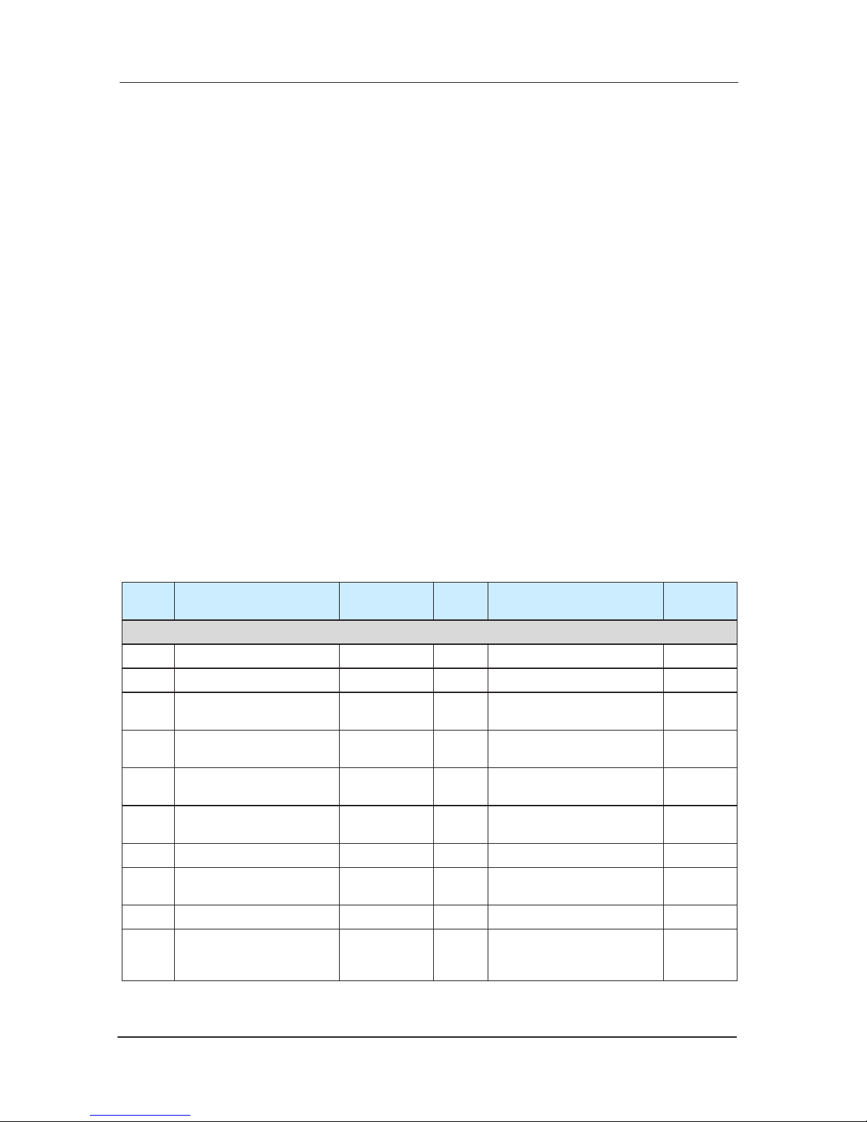
Instruction of Elevator Integrated Control Function, NICE 30001)
Serial
Number
Function Remark
Serial
Number
Function Remark
Standard functions
1 Maintenance Operation 41 Current aslant remove
2 Direct stopping 42 User setting inspection
3
The best curve generated
automatically
43 Peak service
4
Self-rescue leveling
running
44
Real-time clock
management
5
Attendant operation
45 time-sharing services
6
Fire back to the base
oor
46 Security oor at night
7 Firemen Operation 47 Attendant diverting
8 Testing running 48
Deputy operation panel
operation
9 Independent running 49 Car arrival gong
10
emergency rescue
running
50 Outside approaching lamp
Configure
MCTCHCB-B
Page 3
NICE3000 User Manual Preface
3
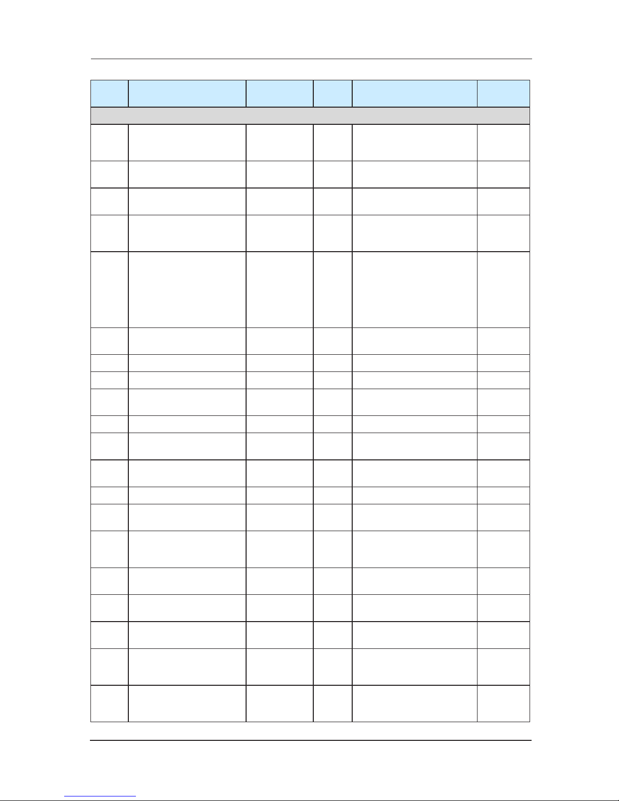
Serial
Number
Function Remark
Serial
Number
Function Remark
Standard functions
11
re-leveling when the door
is open
Configure
MCTC-
SCB-A
51 Outside arrival gong
Configure
MCTCHCB-B
12
Automatic back to the
base oor
52
Double outside -call in the
same oor
13 Parallel Operation 53
forced deceleration
monitoring function
14
Group control adjustment
operation
Configure
MCTCGCB-A
54
Call conglutination
judgment
15
Lift paramete
r
identification with no load
(Permanent
Magnet
Synchronous
Machine is
rotary
coder angle
recognition
55
Weighing signal
compensation
16
Shaft parameters autolearning
56 Leveling fine-tuning
17 Staircase lock function 57 Next landing
18 Full load by pass 58 Failure record
19
lighting、fan energysaving function
59
Short-circuit test against
the earth
20 Service oor set 60 Overload Protection
21
Car location automatica
lly
correct
61
Door light curtain
protection
22
Cancel the wrong
direction
62
Non-open outside door
zone
23 Reverse cancelling 63 Protection of reverse travel
24
Floor service set for front
door and back door
64 anti-slip protection
25 Advanced open
Configure
MCTC-
SCB-A
65
Contact inspection
protection of contactor
26 Repetition of door closing 66
Motor over-current
protection
27
Open the door outside
this hall
67
Power so
urce over-voltage
protection
28
Closing button for doorclosing in advance
68 Motor overload protection
29
Choice of open and
close the door control
protection
69 Encoder fault protection
30
Category setting for the
time of keeping door
open
70
Shaft auto-tuning failure
judging
Page 4
Preface NICE3000 User Manual
4
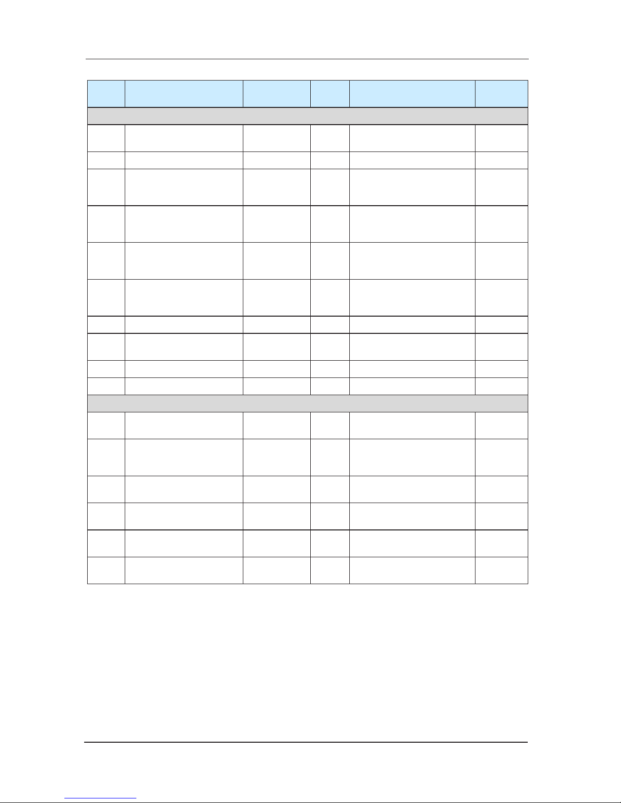
Serial
Number
Function Remark
Serial
Number
Function Remark
Standard functions
31 Keep open function 71
Drive module overheat
protection
32 Outside-call display by bit 72 Door switch fault protection
33
Rolling show the direction
of running
Configure
MCTCHCB-H
73
protection of door-lock
disconnect when running
34
Dot matrix display lift
status
Configure
MCTCHCB-H
74 limit switch protection
35 Show jumping oor
Configure
MCTC
-
HCB-H
75 Over-speed protection
36 Anti-nuisance function
Configure
car weighing
equipment
76
leveling switch fault
protection
37 Full selective 77 CPU fault protection
38 Up selective 78
Output contactor abnormal
detection
39 Down selective 79 Door lock jump protection
40 Separate wait
Optional function
1
IC card user
management
7
toggle group control lift
Service oor
2 Quarter monitoring
Configure
MCTCBMB-A
8 nudging
3
Motor t
emperature
protection
9 VIP oor Service
4 voice announcement 10
Handicapped operation
box operate
5 Earthquake function 11
Back door operation panel
operate
6
front and back door
independent control
Attention:
The standard function is product’s standard configured function, the optional function a)
is the specially provide software service.
Our company does not charge additional for the software part in the opti
onal function.b)
Page 5
NICE3000 User Manual Preface
5
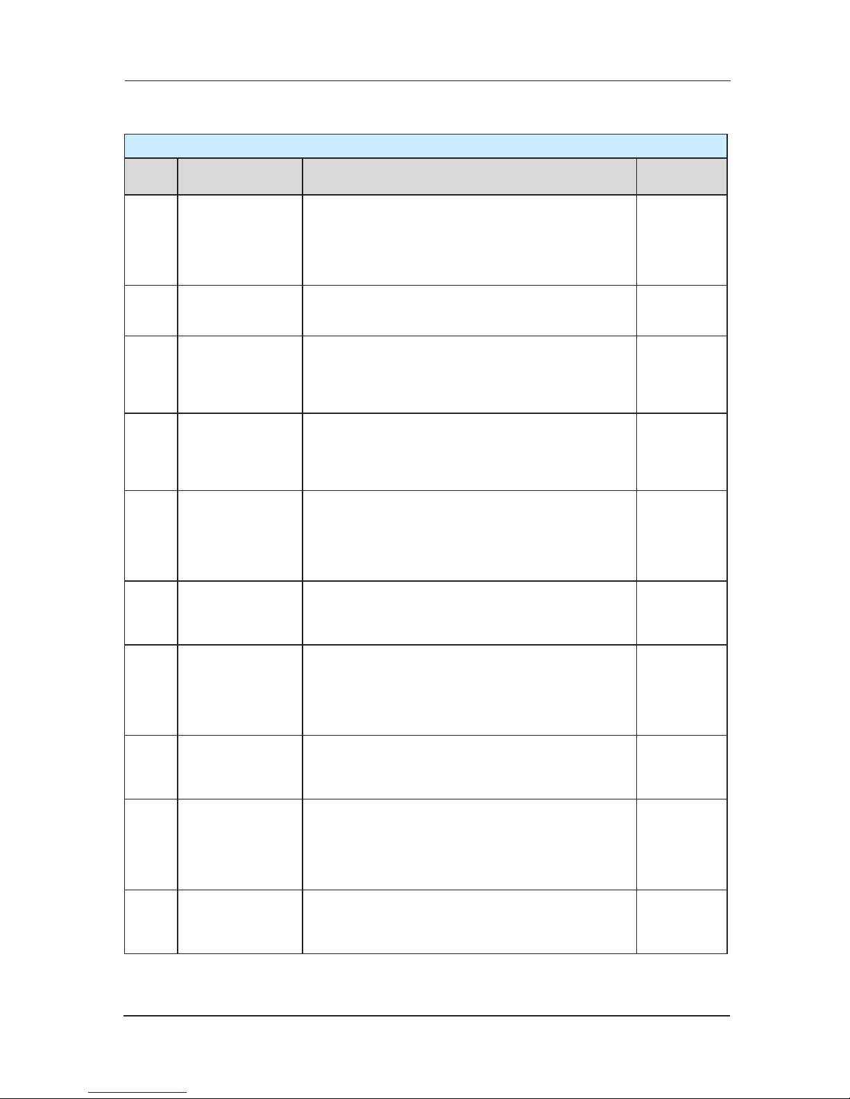
Function Explanation2)
Standard Function
Serial
number
Function name Function introduction Remark
1
Maintenance
Operation
Elevator access to the overhaul state, the system
automatically canceled and the operation of automatic
doors. By the upper (lower) line will enable the
elevator button to overhaul the speed of movement of
the point (down) operation. Release the button to stop
the lift immediately
Standard
Settings
2 Direct
stopping
To the principle of distance, Automatically generate the
smooth curves from start to of parking, no crawling,
directly stop in the leveling position
Standard
Settings
3
The best curve
generated
automatically
Systems automatically computing the most suitable
for the principle of human-machine function curve
according to the distance needed to run, and is not
subjected to restrictions on short
oor and the number
of constraints
Standard
Settings
4
Self-rescue
leveling
When the elevator is in a state of non-maintenance,
and did not stop at the leveling. If it meets the safety
requirements to run .the lift will automatically run
slowly to the nearest oor area, and then open the
door
Standard
Settings
5
Attendant
operation
Through the toggle switch in operation panel can
choose the driver op
eration, the driver can choose
the direction and other functions (such as straight
running function) The elevator close the door under
the condition of the driver sustained press the close
button.
Standard
Settings
6
Fire return to the
base oor
Receive the fire signal, the elevator will not respond
to any calls and inside command .the elevator run the
fastest way to the fire station and then open t
he door
and stop
Standard
Settings
7
Firemen Operation
In the operation of fire mode, the door does not
automatically open or close. Only press the button can
make the door action. The lift only response to one
command in car once. Only when the elevator open
the door stopped at the base station , reset the fire
switch and fireman switch, the lift can run normally
Function
Selection
8 Testing running
Tes
t run including new lifts fatigue test run, ban the
door action ,ban respond to outside-call , shielding of
end station limit switch, shielding of overloading signal,
etc
Function
Selection
9
Independent
running
Elevator does not response to outside –call and close
the door automatically (when the elevator in parallel
control and group control, In order to supply special
services for specific persons
to carry VIP persons or
goods. Press the independent running button then the
elevator out of group control, independent running)
Function
Selection
10
Emergency rescue
running
For the elevator motor which Human force upgrading
the car with rated load lager than 400N Set emergency
electrical running switch and operation to replace
manually upgrading.
Function
Selection
Page 6
Preface NICE3000 User Manual
6
Standard Function
Serial
number
Function name Function introduction Remark
11
re-leveling when
the door is open
The lift stop at the oor station, a large number of
persons or goods entering and leaving, The leveling
uctuated because of the elastic deformation of
elevator Wire Rope and the rubber. System allows
run automatically at the speed of re-leveling to leveling
station in the state of the doo
r opened
Configure
MCTCSCB-A
12
Automatic back to
the base oor
when beyond the setting time and there is no insidecall and outside-call ,elevators automatically return to
the base station and wait for passengers
Standard
Settings
13 Parallel Operation
Two elevators through Serial communication (can
bus) for data transmission. coordinate outside-call and
improve operational efficiency
Function
Selection
1
4
Group control
adjustment
operation
Multiple elevators through Serial communication (can
bus) for data transmission. Calculate the most efficient
and effective operation mode in response to outside
calls.
Configure
MCTCGCB-A
15
Motor parameter
auto-tuning with no
load
For induction motors control system can automatically
recognize the motor resistance, inductance, control
parameters, no-load current to
accurately control the
motor. As for the permanent magnet synchronous
motor, control system can identify the angle of rotary
encoder
Permanent
magnet
synchronous
motor for
identify
the rotary
encoder
angle
16
Shaft parameters
of self-learning
Before the first run, system must self-learn the shaft
parameters. Including the story on each oor, forced
deceleration switch, limit switch position.
Standard
Settings
17
Elevator-locking
function
In automatically run state, after the elevator locked,
the system eliminates all calls registered and then
return to elevator-locked base station then open the
door. After that the elevator stops running, closing the
light and fan in car. When the lock switch has been
reset the elevator re-entered to normal service state.
Standard
Settings
18 Full load by pass
Unde
r the condition of run automatically without the
driver, when the car with full load (generally is 80 ℅
rated load) the elevator does not respond to outsidecalls in passing oor. However, this time outside-calls
can still be registered; it will be serviced next run-time
(single control), or by other elevator services (group
control)
Standard
Settings
19
lighting、fan
energy-saving
function
When beyon
d the setting time and there is no insidecall and outside call the elevator will automatically
turn off the light and fan in car
Standard
Settings
20 Floor service set
System can be exible choose to shut down or
activate one or more elevators service oors and stop
oors for its own needs
Function
Selection
21
Car location
automatically
correct
when the elevator run to the end station ,the system
aut
omatically inspection and rectification of the
location information based on the first level forced
deceleration switch .At the same time, assisted by a
special rate of forced deceleration
Standard
Settings
Page 7
NICE3000 User Manual Preface
7
Standard Function
Serial
number
Function name Function introduction Remark
22
Cancel the wrong
direction
Passengers can press the command button
continuously twice in the control box to cancel the last
error registration instructions.
Standard
Settings
23 Reverse cancelling
When the elevator run to the end oor or the direction
changed, system cancel all calls registered of the
reverse directions.
Standar
d
Settings
24
Floor service set
for front door and
back door
System can select service oors respectively through
the front door and back door for its own needs
Function
Selection
25 Advanced open
Under the automatic operation state,the speed
during stopping is less than 0.1m/s and the gate
signals effective, system shorted door-lock signal
through advanced door-opening module and then
open the door a
head of time to make the elevator
efficiency
Configure
MCTCSCB-A
26
Repetition of door
closing
After the elevator continuing close the door for a
certain time, If the door-lock has not been closed,
the elevator opens the door automatically, and then
repeats the close the door.
Standard
Settings
27
Open the door
outside this hall
under the condition that there is no other command
or outside-call ,if the c
ar stop at a oor, press the call
button this oor, the door automatically open
Standard
Settings
28
Closing button for
door-closing in
advance
when Elevator in the automatic operation mode and
the door is open, it can through the close button to
close the door ahead of time to make the elevator
efficiency
Standard
Settings
29
Choice of open
and close the door
control protection
System can exible set wh
ether continuous output
commands after open the door in place, closed in
place in accordance with the type of door
Function
Selection
30
Category setting
for the time of
keeping door open
System can automatically identify different time to
keep the open of calls to open the door, instructions
to open the door, the door to protect open, delay to
open the door to open the door in accordance with the
s
etting time
Standard
Settings
31
Keep open
function
By press the keeping the door open button ,the
elevator delay closing to meet the need of carrying
goods
Standard
Settings
32
Hall call display by
bit
System allows the display of each oor using the 0-9,
as well as any letters of permutation and combination
of characters for use of the special conditions.
Standard
Settings
33
Rolling show the
directio
n of running
During the elevator running, the display outside shows
the direction of running
Configure
MCTCHCB-H
34
Dot matrix display
lift status
through the dot matrix it shows the direction of the
elevator, the oor elevator stops, elevator status(such
as failure, overhaul) etc.
Configure
MCTCHCB-H
35 Show jumping oor
exible defining the outside display panel display
,show non-continuous data for its o
wn needs
Configure
MCTCHCB-H
Page 8
Preface NICE3000 User Manual
8
Standard Function
Serial
number
Function name Function introduction Remark
36
Anti-nuisance
function
System identifies the number of passengers in car and
Automatically determines the number of passengers
inside and comparison with the instructions registered
in car. If an excessive number of calls registered, then
the system considers it is anti-nuisance status and
cancels all the calls in car. You need
to re-register
correct calls
Configure
Car weighing
equipment
37 Full selective
when the elevator running in automatic or driver state
will be responded to inside-call signal meanwhile
responded to hall call button signals, any service oor
can call the elevator by register the up and down
signal
Standard
Settings
38 Up selective
when the elevator running in automatic or driver state
will be responded
to inside-call signal meanwhile
responded to outside-call button signals, any service
oor can call the elevator by register the up signal
Function
Selection
39 Down selective
when the elevator running in automatic or driver state
will be responded to inside-call signal meanwhile
responded to outside-call button signals, any service
oor can call the elevator by register the down signal
Function
Selec
tion
40 separate wait
only the system with parallel or group control can
select this function, when elevators in parallel or group
control in the same oor, parallel or group control will
began to spread the elevators, make the elevator run
to the free oor
Function
Selection
41
Current aslant
removal
when use permanent magnet synchronous motor, after
the elevator decelerating and stopping, the mainta
in
current of the motor removed by the slope way to
abnormal noise of the motor during the process
Function
Selection
42
User Preferences
inspect
Users can find the system parameters which is
different from the factory parameters by this function
Function
Selection
43 Peak service
Parallel peak is in the peak time set, if the inside-call
from this peak oor is more than 3, then system in
peak service. t
he inside-call effective all the time, the
elevator is free it will be go to this oor
Function
Selection
44
Real-time clock
management
System have real-time clock chip to guarantee the
clock work normal in 2 years
Function
Selection
45
time-sharing
services
Flexible setting the time-sharing service time period
and the corresponding time-sharing service oors.
Function
Selection
46 Guard oor at night
Pro
tect oor of elevator, when 22 o’clock to 6
o’clock the Protect oor is valid, the elevator will
be running to the Protect oor every time when the
elevator running, stop at the protect oor to open
the door and then run to the target oor to improve
security
Function
Selection
47 Drivers reversing
Drivers choose the direction of the elevator through a
special button
Standard
Settings
48
Deputy operati
on
box operation
manipulation matching box can be selected if the
system have the main control box, the manipulation
matching box also equipped with a command button
and the door button switch and the function is the
same as the main control box
Standard
Settings
Page 9
NICE3000 User Manual Preface
9
Standard Function
Serial
number
Function name Function introduction Remark
49 Car arrival gong
After the elevator arrival at the destination oor in
accordance with the requirements of passengers, the
car top board sent the signal.
Standard
Settings
50
Outside
approaching gong
After the elevator reach the oor,through MCTCHCB-B sent outside lights arrival forecasting
Configure
MCTCHCB-B
51
Outside arrival
go
ng
After the elevator reach the oor,through MCTCHCB-B sent outside clock
arrival forecasting
Configure
MCTCHCB-B
52
Double hall call in
the same oor
Double hall-call can be set when opposite door in the
same oor
Function
Selection
53
Forced
deceleration
monitoring function
System in automatic operation mode correcting the
location of the elevator car according to the forced
deceleration switch posi
tion , as well as the action
switches to monitor the situation
Standard
Settings
54
Call conglutination
judgment
System can identify the conglutination situation of the
hall call button, automatically remove the call of the
adhesion to avoid the elevator can not be closed to
run caused by the hall-call button conglutination
Function
Selection
55
Weighing signal
compensation
in high-end applications Sy
stem can use weighing
signal to compensate the start of the elevator
Function
Selection
56
Leveling finetuning
system can be fine-tune the accuracy of leveling by
adjust the f4-00 parameter
Standard
Settings
57 Next landing
If the elevator continued to open the door more than
the time of open the door, the open limit has not yet
been act, the elevator would be turned into the closing
door state, and aft
er the door closed, automatically run
the next registered oor
Standard
Settings
58 Fault record
System recorded 11 faults, including fault resulting
from information such as time and oors.
Standard
Settings
59
Short-circuit test
against the earth
When first supply power, the system test output U, V,
W to determine whether the existence of short-circuit
fault.
Standard
Settings
60
Overload
Protection
When
the lift when the load over the rated load;
elevator alarm, stop the run.
Standard
Settings
61
Light curtain
protection
When something block in the middle of the door during
the door is closing, the light curtain protection action
then the elevator turn to open the door. But the light
curtain protection does not work in the fire operation.
Standard
Settings
62
Non-open outside
door zone
Prohibit open th
e door automatically when system not
in gate-area
Standard
Settings
63
Protection against
reversal travel
System identify the direction of rotary encoder
feedback signals,determining the actual direction of
the motor in operation,once the signal reversed the
system will be alarm
Standard
Settings
Page 10
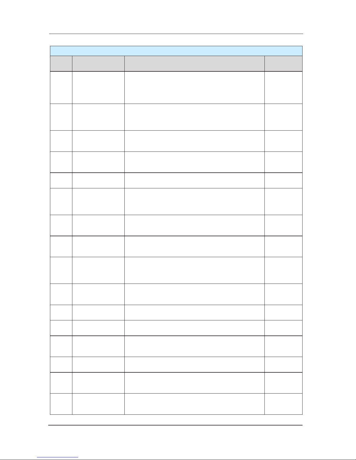
Preface NICE3000 User Manual
10
Standard Function
Serial
number
Function name Function introduction Remark
64 Anti-slip protection
When the elevator not running in overhaul state, if
the elevator continuous running beyond the F9-02 set
time (maximum 45 seconds) and the leveling switch
not act. system will regard this as detect the rope slip
fault, so stop the car all running
Standard
Settings
65
Trigger point
detection
protection of tri
gger
if system detect the contactor on abnormal state when
the elevator in running or stopping state, the system
will automatically protect
Standard
Settings
66
Motor over-current
protection
When detecting the motor current value is greater
than the maximum allowable, the system automatic
protection
Standard
Settings
67
Power source overvoltage protection
When Detecting the power supply voltage is grea
ter
than the maximum allowable value, the system
automatic protection
Standard
Settings
68
Motor overload
protection
When detecting the motor is overload
,the system automatic protection
Standard
Settings
69
Encoder fault
protection
System only use a high-speed encoder for closed
loop vector control, if the encoder failure, the system
stop automatically to avoid the runaway failure which
caused by the e
ncoder failure not available.
Standard
Settings
70
shaft auto-tuning
failure judgment
Without right shaft data, the elevator will not be able to
running. so we set the self-learning fault diagnostic if
the shaft self-learning does not properly completed
Standard
Settings
71
Drive module
overheating
protection
When detecting the drive module overheating, the
system automatic protection
Standard
Settings
72
Door switch fault
protection
When detecting the elevator not yet close the door
effective after the elevator open and close the door
beyond the number set, system stop close and open
the door switch and output the fault.
Standard
Settings
73
Protection of doorlock disconnect
when running
when the door-lock disconnected during the elevator
is running, the system automatic protection
Standard
Setting
s
74
Limit switch
protection
If the Up (down) limit switch action, the elevator ban
on run to up(down),but to run to the opposite direction
Standard
Settings
75
Over-speed
protection
Assurance the speed of car in the range of security
speed to ensure the passengers and cargo security.
Standard
Settings
76
leveling switch fault
protection
When the elevator in the automatic running mode, it
identify levelin
g signal loss and adhesion status.
Standard
Settings
77
CPU fault
protection
System has three CPUs to judge state each other, if
there is abnormal, the system block all output.
Standard
Settings
78
Output contactor
abnormal detection
By detecting the output current situation to determine
whether the output contactor is abnormal before the
brake open.
Standard
Settings
79
Protection against
false door lo
cking
Elevator in the automatic running mode identify
whether the door-lock is anomalies every time open
the door in place
Standard
Settings
Page 11
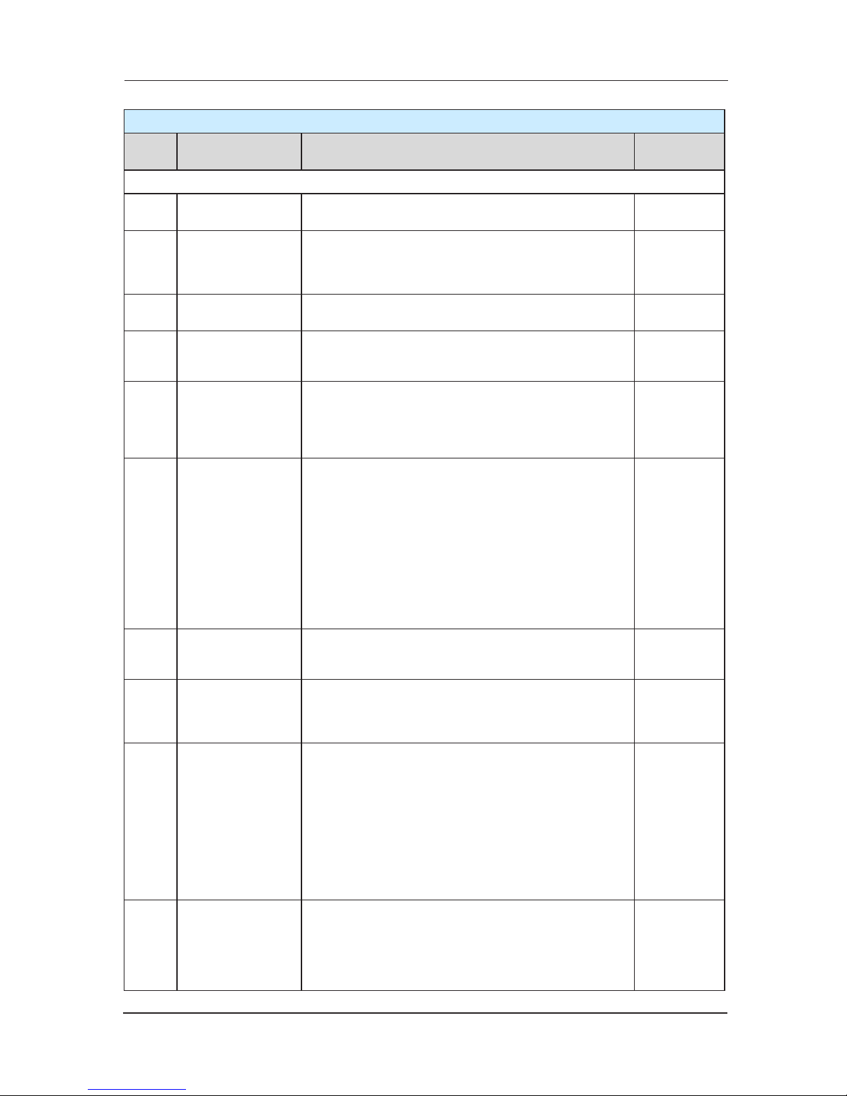
NICE3000 User Manual Preface
11
Standard Function
Serial
number
Function name Function introduction Remark
Optional function
1
IC card user
management
Passengers must be licensed before they can reach
the authorized oor
2 Quarter monitoring
Through communication lines, control systems
connect to the terminals installed in the control room
to display the elevator location, direction, fault status
and so on.
Configure
MCTCBMB-A
3
Motor temper
ature
protection
when System detects motor temperature overheating,
suspend the elevator running
4
voice
announcement
when the elevator running ,it will automatically
broadcast to the direction of running and the oor next
reaching and other information passengers
5 Seism function
If the earthquake happens, earthquake detection
devices act. the device has a contact signal input to
the NICE system, the
system will control the elevator
stop at the nearest oor and then open the door stop
running
6
front and back
door independent
control
the front and back door (front and back doors
operation panel, the front and back doors call box
exist) independent control operation: If the back
door call-box (or back-door directions) call registered
this oor before leveling, open the back door when
the elevator
stop; If the front door call-box (or frontdoor directions) call registered this oor before
leveling, open the front door when the elevator stop.
If registered both side, open two doors. In this oor,
similarly, open the back door when press the button on
back door call-box, open the front door when press the
button on front door call-box.
7
switch group
control lift Service
oor
freely set up serv
ice oor Based on time parameters
8 nudging
When nudging function effective, if there are no close
signal in continuing 60 seconds because light curtain
act or other reason. the elevator will nudging and sent
the nudging signal
9 VIP oor Service
when need VIP service, click the VIP switch and
the elevator will carry out a VIP service operation:
cancel all the call and registered command ,the
elevator
straight run to VIP oor and open the door.
The elevator can’t close the door automatically and
can’t register outside-call but can registered insidecall. service who escort the VIP register the target oor
command, sustaining press the close button to make
the door closed ,the elevator straight to the destination
oor, open the door and then the elevator turn to
normal
10
Handicapped
operation box
operate
when the elevator wait in leveling position, if call from
handicapped operation panel registered in this oor,
then the time which the elevator keep the door open
extend; similarly, if the door open after press the open
button on handicapped operation panel, the time is
also extend
Page 12

Preface NICE3000 User Manual
12
Page 13

Contents
Preface ……………………………………………………………………………………… 1
Chapter 1 Safety information and attention items ………………………… 16
1.1 Safety Items …………………………………………………………………………… 16
1.2 Attention Items ………………………………………………………………………… 19
Chapter 2 Product information …………………………………………… 22
2.1 Name Designation Rules and Nameplate ……………………………………………22
2.2 main parameters of NICE3000 integrity controller ………………………………… 23
2.3 Techn
ical Specification …………………………………………………………………24
2.4 Product Appearance ……………………………………………………………………25
2.5 Daily Maintenance of Controller ……………………………………………………… 27
Chapter 3 Structure of the control system and the component introduction 30
3.1 Using Introduction of CTB …………………………………………………………… 30
3.2 Using introduction of CCB …………………………………………………………… 33
3.3 Direction for use of HCB ……………………………………………………………… 37
3.
4 Sort of adjusting tools for NICE 3000 ………………………………………………… 53
3.5 Advanced door-open module(SCB) ……………………………………………… 60
3.6 Voice landing report (CHM) ……………………………………………………………63
3.7 Weighing sensor (LDB) ………………………………………………………………… 64
3.8 IE module Applied to the elevator faults conditions the MCTC-IE-A …………… 67
3.9 Other optional components …………………………………………………………… 68
Chapter 4 Installation and wiring …………………………………………… 70
4.1 System Configure Introduction ……………………………………………………… 70
4.2 Mechanical Installation …………………………………………………………………70
4.3 Electric Installation and Wiring ……………………………………………………… 71
Chapter 5 Function parameters tables …………………………………… 82
5.1 Function parameters Indication ……………………………………………………… 82
5.2 Function Parameters Tables ………………………………………………………… 83
Chapter 6 Function parameter description ………………………………… 102
6.1 F0 Group Basic Function Group ………………………………………………… 102
6.2 F1 Group Motor Parameters ……………………………………………………… 103
Page 14

6.3 F2 Group Vector Control Parameters …………………………………………… 110
6.4 F3 Group Running Control Parameters ………………………………………… 112
6.5 F4 Group Position Parameters …………………………………………………… 116
6.6 F5 Group Terminal Function Parameters ……………………………………… 117
6.7 F6 Group Lift Basic Parameters ………………………………………………… 128
6.8 F7 Group Testing Function Parameters ………………………………………… 131
6.9 F8 Group Reinforce Function Par
ameters ……………………………………… 133
6.10 F9 Group Time Parameters ……………………………………………………… 135
6.11 FA Group Keyboard Setting Parameters ……………………………………… 136
6.12 FB Group Door Function Parameters ………………………………………… 140
6.13 FC Group Protection Function Parameters …………………………………… 143
6.14 FD Group Communication Parameters ………………………………………… 145
6.15 FE Group Lift Function Setting Parameters …………………………………… 145
6.16 F
E Group Factory Parameters (Reserved) …………………………………… 152
6.17 FP Group User Parameters ……………………………………………………… 152
Chapter 7 System typical application and adjustment …………………… 154
7.1 Lift Adjustment ……………………………………………………………………… 154
7.2 Production Use ……………………………………………………………………… 161
7.3 NICE3000 Integrated controller without weighing application notes …………… 162
7.4 Power failure emergency running program in
struction ………………………… 163
7.5 Parallel program instruction ………………………………………………………… 167
7.6 Instruction of group control program ……………………………………………… 170
7.7 Instruction of overload and full load ……………………………………………… 170
Chapter 8 Fault diagnosis and countermeasures ……………………… 174
8.1 Fault mode explanation …………………………………………………………… 174
8.2 Fault information and countermeasures ………………………………………… 174
Page 15

Safety information and attention items
1
Page 16
Safety information and attention items NICE3000 User Manual
16
Chapter 1 Safety information and attention items
Safety definition:
There are two kinds of safety items in this manual:
Failure to follow these instructions will result in death or serious injury.
Failure to follow these instructions will result in moderate hurt or equipment
damage
Please read this manual carefully and operate strictly according to the safety items while
installing, debugging, maintaining the system. Our company is free of charge to any damage or
dandification caused by the operation not performed according to the requirements.
1.1 Safety Items
1.1.1 before Installation
Do not install in the condition of water seepage in the control system, components
scarcity or damage while opening the case!
Do not install while the packing list is not according with the practicality!
Please uplift and drop gently in the portage or the equipment will be damaged!
Do not use any controller that is damaged or not complete. There’s danger of
getting hurt!
Do not touch the elements of the controller with your hands, or the static electricity
damage may be caused!
1.1.2 during Installation
Please mount the controller on incombustible surface like metal, and keep away from
ammable substances! Otherwise it may cause fire!
Do not twist the fixing bolts of the components, especially the bolts with red marks!
Do not let wiring terminal or screw enter the controller, otherwise the controller will be
damaged!
Install the controller where there’s less shaking and less sunshine.
1.1.3 Wiring
Page 17
NICE3000 User Manual Safety information and attention items
17
Only the qualified electrical engineer can perform the wiring, otherwise there will be
danger of electric shock.
A circuit breaker must be installed between the mains and the controller; otherwise
there will be danger of fire.
Wiring can only be done after the mains input are cut off; otherwise there will be
danger of electric shock.
Please connect the controller to the ground according to the st
andard, otherwise there
will be dangerous
Do not connect the input terminals with the output terminals (U, V, W). Please note
the marks and do not connect the wrong wires otherwise the controller may be
damaged!
Ensure the wiring meet the EMC requirements and the local safety standard. The wire
size shall be determined according to the manual, otherwise accidents may occur!
Brake resistor must not be connected between the DC bus termina
ls (+) and (-),
otherwise fire may occur!
Encode connection must use Shielded line, shielding layer must be one side
connected to earth reliably!
Communication wires must use STP with the length of the lay between 20mm and
30mm, shielding layer must be connected to earth!
1.1.4 before Power-on
Please confirm the mains voltage level is consistent with that of the controller ;the
input (R,S,T) and output (U,V,W) wirings are correct; and check if there is any short
circuit in peripheral circuit and if the wiring is fixed and fast; otherwise the controller
may be damaged!
Ensure the synchronous motor has done the dynamic auto-tuning and try to run the
motor before restoring wire ropes.
No p
arts of controller must be through the over-voltage testing since it has been done
in the factory; Otherwise accidents will occur!
Mount the cover plate properly before power-on the controller; otherwise there will be
danger of electric shock!
All the external equipment wirings must be connected according to the instruction of
this manual, or accidents may occur!
Page 18
Safety information and attention items NICE3000 User Manual
18
1.1.5 after Power-on
Do not open the cover of the controller after power-on; otherwise there will be danger
of electric shock!
Do not touch the controller and its circuit with wet hand; otherwise there will be
danger of electric shock.
Do not touch the controller terminals; otherwise there will be danger of electric shock.
At power-on, the controller will perform the security check of the external heavy-
current c
ircuit. At this time do not touch U, V, W terminals of controller or the wirings
terminals of the motor; otherwise there will be danger of electric shock!
If parameter identification is required, please pay attention that the rotating motor may
injure people, otherwise accident may occur!
Do not change the factory settings; otherwise the current may be damaged!
1.1.6 Running
Do not touch the fan and the discharging resistor to check the temperature, otherwise
burning will occur!
Only the qualified technician can check the signal while it’s running. Otherwise there
will be danger of personal injury or equipment damage!
Do not let objects fall into a running controller; otherwise the controller may be
damaged!
Do not start and stop the controller by on/off of the contactor, otherwise the
controller may be damaged.
1.1.7 Maintenance
Please do not repair or maintain the controllers with power on, otherwise there will be
danger of electric shock!
Ensure the repair and maintenance of the controller is operated in the condition that
the controller voltage is below AC36V, two minutes after the power is switch-off.
Otherwise the residual Charge in the capacitor will injure people.
Only qualified electrical engineer can repair or m
aintain the controller, otherwise there
will be danger of human injury or damaging the equipment.
Reset the parameters after changing the controller; all the insets must be unplugged
while the power is switch-off!
Page 19

NICE3000 User Manual Safety information and attention items
19
1.2 Attention Items
1.2.1 Motor insulation check
When the motor is used for the first time, or reused after storing for a long time, or in a regular
checkup, the user must check the insulation of the motor to prevent the poor insulation of the
windings of motor from damaging the controller. The motor connection must be divided from
the controller during the insulation check. It is recommended to use
a 500V Mega-Ohm-Meter
to check and the insulation resistance shall not be less than 5MΩ.
1.2.2 Thermal Protection of Motor
If the rated capacity of the motor selected is not matching that of the controller, especially
when the rated power of the controller is bigger than that of the motor, make sure to adjust the
parameters for motor protection inside the controller or to install a thermal relay to
the motor to
guarantee the protection to the motor.
1.2.3 Motor Heat and Noise
Since the output voltage of the controller is in PWM wave with some harmonic wave, the
temperature may raise, the noise and vibration may increase compared with the controller
running at main frequency.
1.2.4 Pressure-sensitive Device or Capacitor at the Output Side of the Controller
Because the controller outputs PWM wave,
the capacitor used for improving power factor and
pressure-sensitive resistor used for lightening-proof shouldn’t be installed at the output side of
the controller. Otherwise the controller may have transient over-current and may be damaged.
1.2.5 Switches Used at the Input and Output terminal of the Controller
If the contactor is required to be installed between the controller input terminal and t
he power
supply, it is prohibited to start or stop the controller with the contactor. If the switches like
contactors are connected between the output terminal and the motor, make sure to start and
stop the controller when the controller has no outputting, otherwise the modules in the controller
may be damaged.
1.2.6 Usage out of the Range of Rated Voltage
The NICE3000 controller shall not be used o
ut of the specified range of operation voltage.
Otherwise the internal components of the controller may be damaged. If needed, please use
corresponding voltage regulation device to change the voltage.
1.2.7 Lightning Stroke Protection
There are lightning protection devices inside the controller, but the user should install other
lightning protection device at the front end of the controller if light
ning strike occurs frequently.
1.2.8 Altitude and De-rating
When the altitude is higher than 1000m, the cooling effect of consult is deteriorated because
of the rarefaction of air, then it is a necessity to de-rate the use of controller and please contact
our company for detailed technical support in this circumstance.
Page 20

Safety information and attention items NICE3000 User Manual
20
1.2.9 Cautions for Scrap of controller
The electrolytic capacitors in the main circuits and PCB may explode when they are burned
and poisonous gas may be generated when the plastic parts are burned. Please dispose the
controller as industrial rubbish.
1.2.10 About Applicable Motor
The controller is applicable to squirrel-cage Asynchronous motor and AC permanent-magnet
Synchronous motor. Please be su
re to select the applicable controller according to the Data
plate of the motor.
The controller has already been configured with default parameters which is applicable to
squirrel-cage Asynchronous motor. To perform the motor parameter identification according
to the actual conditions will promote the operation effect. Synchronous motor must carry out
parameter tuning.
The output part of controller
should not be short. Otherwise the controller may alarm or be
damaged. Therefore, before Power-on, we must execute short-circuit-test for new elevator.
Please make sure that the controller be cut from the testing parts when the testing is
undergoing.
Page 21

Product information
2
Page 22
Product Information NICE3000 User Manual
22
Chapter 2 Product information
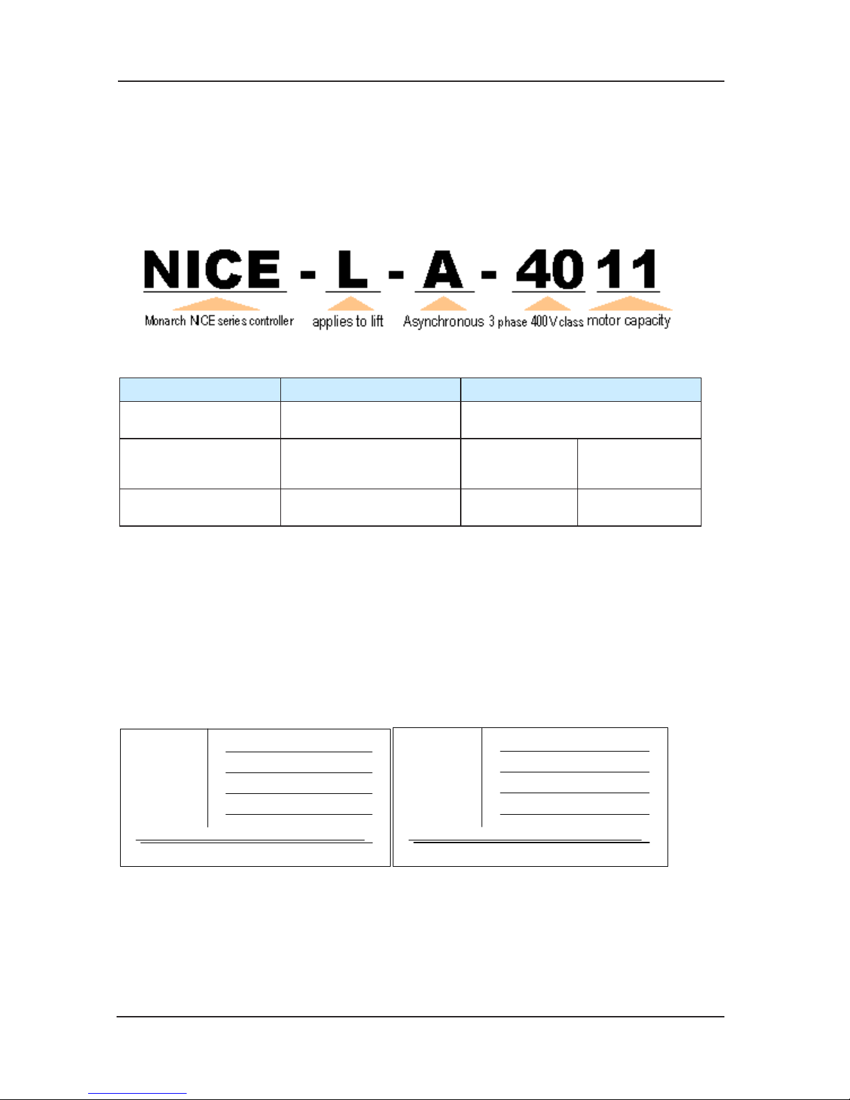
2.1 Name Designation Rules and Nameplate
2.1.1 Applies to Asynchronous/ Synchronous integrated motor:
Name designation rules:
Controller model A B
Applicable to traction
motor model
Asynchronous motor Synchronous motor
Applicable to encoder
motor model
Push-pull, open-
circuit collector output
incremental encoder
UVW SIN/COS
Applicable to PG card No need of PG card
MCTC-PG-B
MCTC-PG-D
MCTC-PG-C
MCTC-PG-E
NICE-L-A-40XX is used in asynchronous traction motor control, and is applicable to pushpull output and open-circuit output incrementa
l encoder. The main control panel has push-pull
encoder itself, so it doesn’t need PG switch card. NICE-L-B-40XX is used in synchronous
traction motor control, and is suitable for UVW encoder and SIN/COS encoder.
Note: NICE-L-B-40XX is the substitution of NICE-L-IP-40XX and NICE-L-IP-40XX-SC, and has
upgraded on the basis of them.
2.1.2 Asynchronous/ Synchronous integrated controller nameplate:
Asyn
chronous motor nameplate: Synchronous motor nameplate:
POWER
OUTPUT
INPUT
MODLE
S/ N
Suzhou MONARCH Control Technology Co.,Ltd.
NICE-L-A-4015
15kW
3PH AC380V 35A 50Hz/60Hz
3PH AC380V 32A 0~90Hz
POWER
OUTPUT
INPUT
MODLE
S/ N
Suzhou MONARCH Control Technology Co.,Ltd.
NICE-L-IP-4015
15kW
3PH AC380V 35A 50Hz/60Hz
3PH AC380V 32A 0~90Hz
Page 23
NICE3000 User Manual Product Information
23
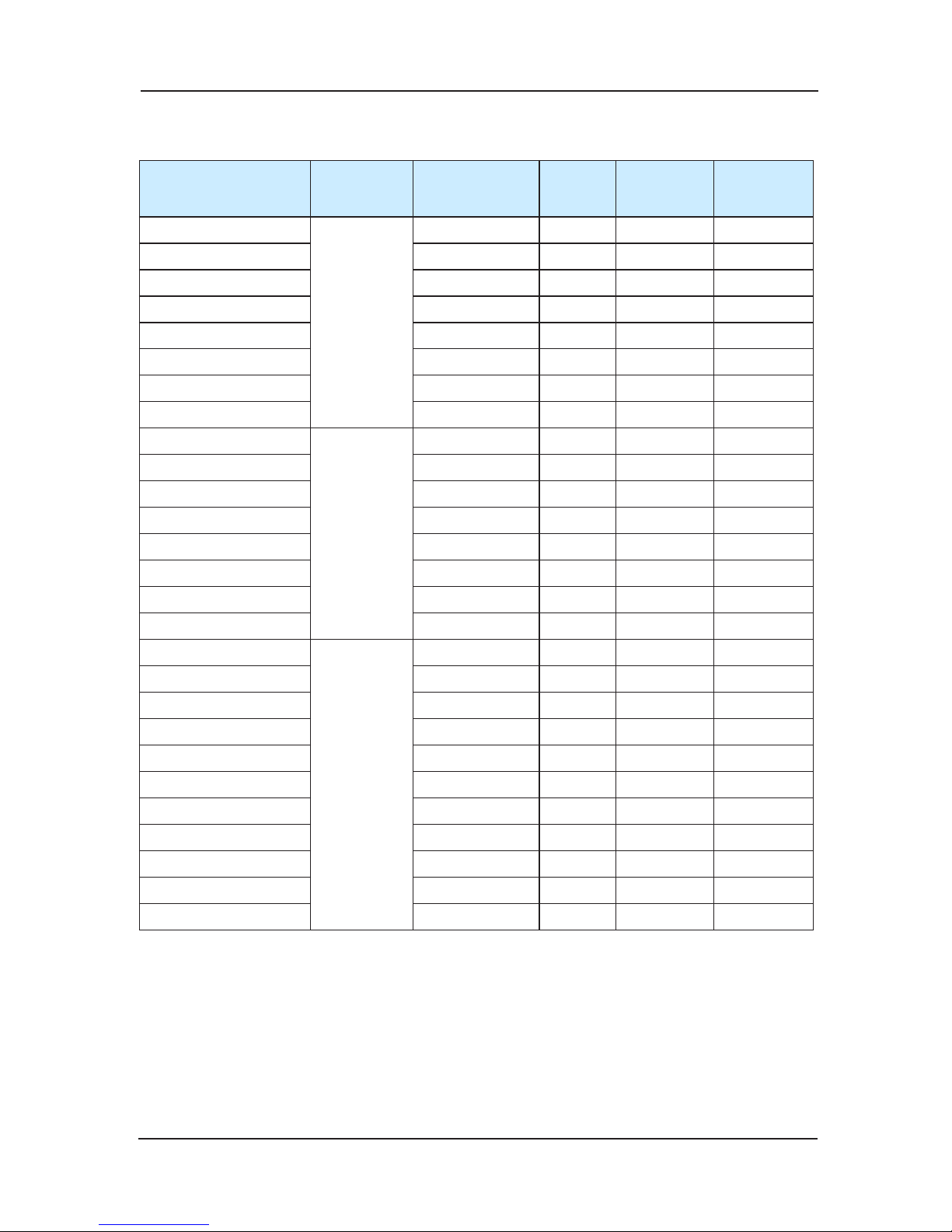
2.2 main parameters of NICE3000 integrity controller
Model
Input
Voltage
Power
Capacity(KVA)
Input
Current
(A)
Output
Current(A)
Motor(KW)
NICE-L-A/B-2002
single
phase 220V
range:
-15%~20%
4 13.2 5.5 1.1
NICE-L-A/B-2003 5.9 17 9.0 1.5
220-NICE-L-A/B-4007 17 29 10.3 5.5
220-NICE-L-A/B-4011 21 36 15.5 7.5
220-NICE-L-A/B-4015 24 41 19 11
220-NICE-L-A/B-4018 30 49.5 22.5 15
220-NICE-L-A/B-4022 40 62 27.7 15
220-NICE-L-A/B-4030 57 77 34.6 22
NICE-L-A/B-2002
three
phase
220V
range:
-15%~20%
4 13.2 9.6 3.7
NICE-L-A/B-2003 5.9 17 15.6 5.5
220-NICE-L-A/B-4007 17 29 18 11
220-NICE-L-A/B-4011 21 36 27 15
220-NICE-L-A/B-4015 24 41 33 22
220-NICE-L-A/B-4018 30 49.5 39 22
220-NICE-L-A/B-4022 40 62 48 22
220-NICE-L-A/B-4030 57 77 60 22
NICE-L-A/B-4002
three phase
380V
range:
-15%~20%
4 6.5 5.1 2.2
NICE-L-A/B-4003 5.9 10.5 9 3.7
NICE-L-A/
B-4005 8.9 14.8 13 5.5
NICE-L-A/B-4007 11 20.5 18 7.5
NICE-L-A/B-4011 17 29 27 11
NICE-L-A/B-4015 21 36 33 15
NICE-L-A/B-4018 24 41 39 18.5
NICE-L-A/B-4022 30 49.5 48 22
NICE-L-A/B-4030 40 62 60 30
NICE-L-A/B-4037 57 77 75 37
NICE-L-A/B-4045 69 93 91 45
Page 24

Product Information NICE3000 User Manual
24
2.3 Technical Specification
Item Specification
Specification
Maximum frequency 90Hz
Carrier frequency
0.5k~16k (Hz); Carrier frequency can be adjusted
automatically according to the load characteristic.
Control mode
Split-ring vector control (SVC)/ Closed loop vector control (VC)
Start torque Type G: 0.5Hz / 180% (SVC), 0Hz/200% (VC)
Speed control range 1 : 100 (SVC) 1 : 1000 (VC)
Speed accuracy ±0.5%(SVC) ±0.05%(SVC)
Torque control accuracy ±5%(VC)
Overload capability
150% rated current for 60 seconds; 200% rated current for 1
second.
Motor tuning No-load tuning, load tuning
Distance control Immediacy stop
Acceleration/deceleration curve
N curves can generate automatically.
Re-leveling Level re-adjusts after the car load changes
Forced deceleration
New and reliable compulsive deceleration function helps to
identify the
deceleration shelf automatically.
Shaft auto-tuning 32-bit data, record the shaft position accurately.
Leveling adjustment Flexible and easy leveling adjustment function
Starting torque compensation Humanized weighing aito-tuning
Real time clock
Based on accurate real time clock, it can accomplish timesharing service, pinnacle service, automatic password, etc.
Testing function
Convenient ways to realize many functions for elevator
adjusting.
Failure protect
Provide 53 kinds of protection such as electrify short circuit
survey、in-out lack phase protect、over current protect、
prevent encoder and so on. A complete elevator faultdealing system
Intellectualized management
Fulfill the function of distance monitoring, user management,
and group adjustment.
Apply power then peripheral
equipment safety auto-
exami
nation
Apply power and do peripheral equipment detection like
grounding、short circuit etc.
State monitoring
According each feedback signal to judge elevator work
state, ensure the elevator work effectively.
Input/output
characteristic
Digital input 24 Digital input terminal,specification:24V,5mA
Analog data input A1 input terminal voltage range:-10V~10V
Communication terminal Canbus (car top) \ Modbus (hal
l call)
Output terminal 6 relay output terminal, adjustable function
Encoder interface
Standard adoptable to incremental push-pull output and
open-loop collector output. coder .
Applicable to different encoder via PG card.
Page 25
NICE3000 User Manual Product Information
25
Item Specification
Display and
keypad
operation panel
5-bit LED display, show parameters of running speed, bus
voltage, etc.
small keyboard
3-bit LED display, displaying the information of main board
MCB and receiving the simple order input
State monitor
Monitor lift state parameters, including car top control board
and hall call control board.
Application
environment
Elevation Lower than 1000m
Ambient temperature
-10℃~ +40℃ ( ambient temperature is within 40℃~ 50℃ ,
and duration is required)
Humidity Less than 95% RH, without condensation
Vibration Less than 5.9m/s
2
(0.6g)
Storage temperature -20℃ ~ +60℃
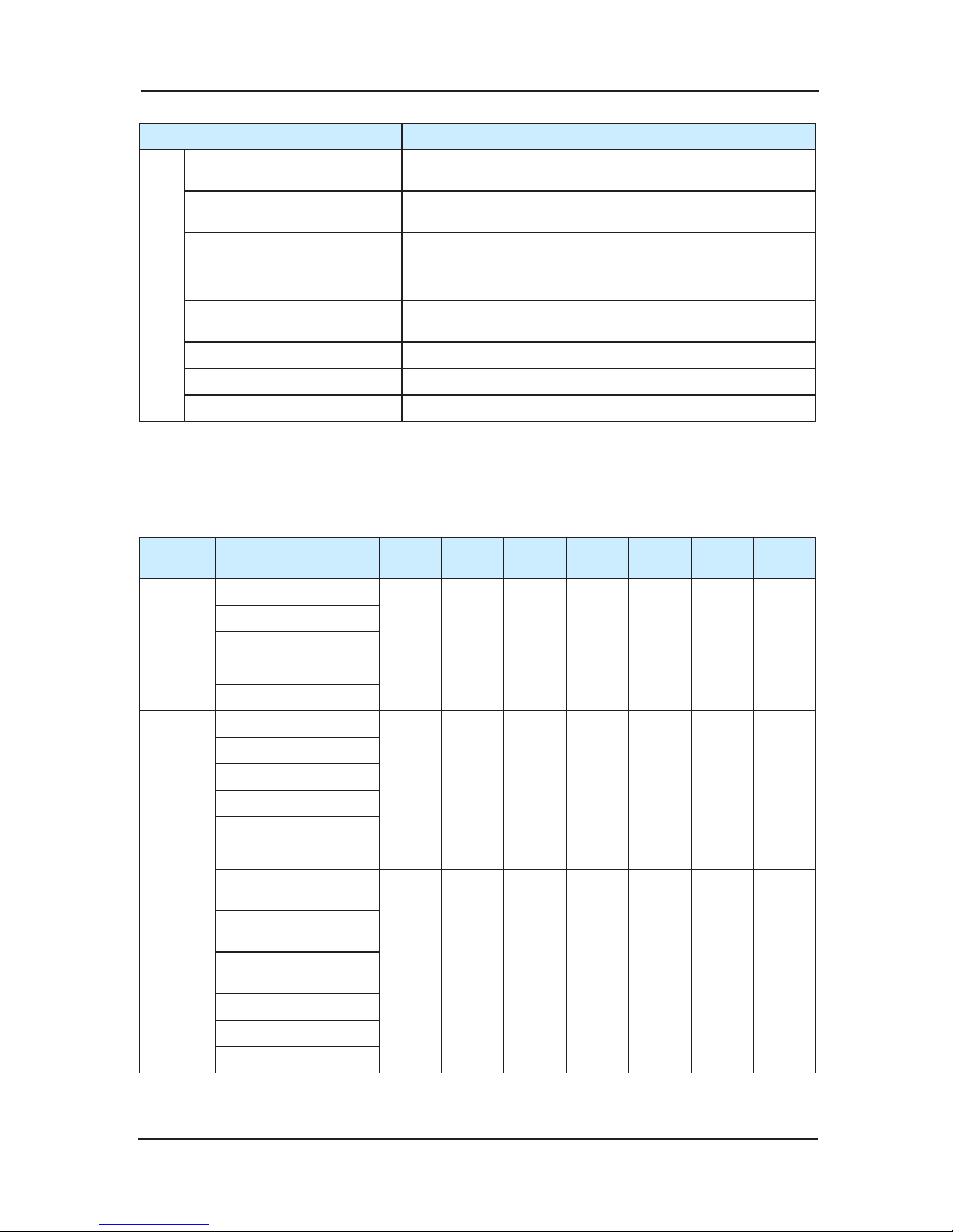
2.4 Product Appearance
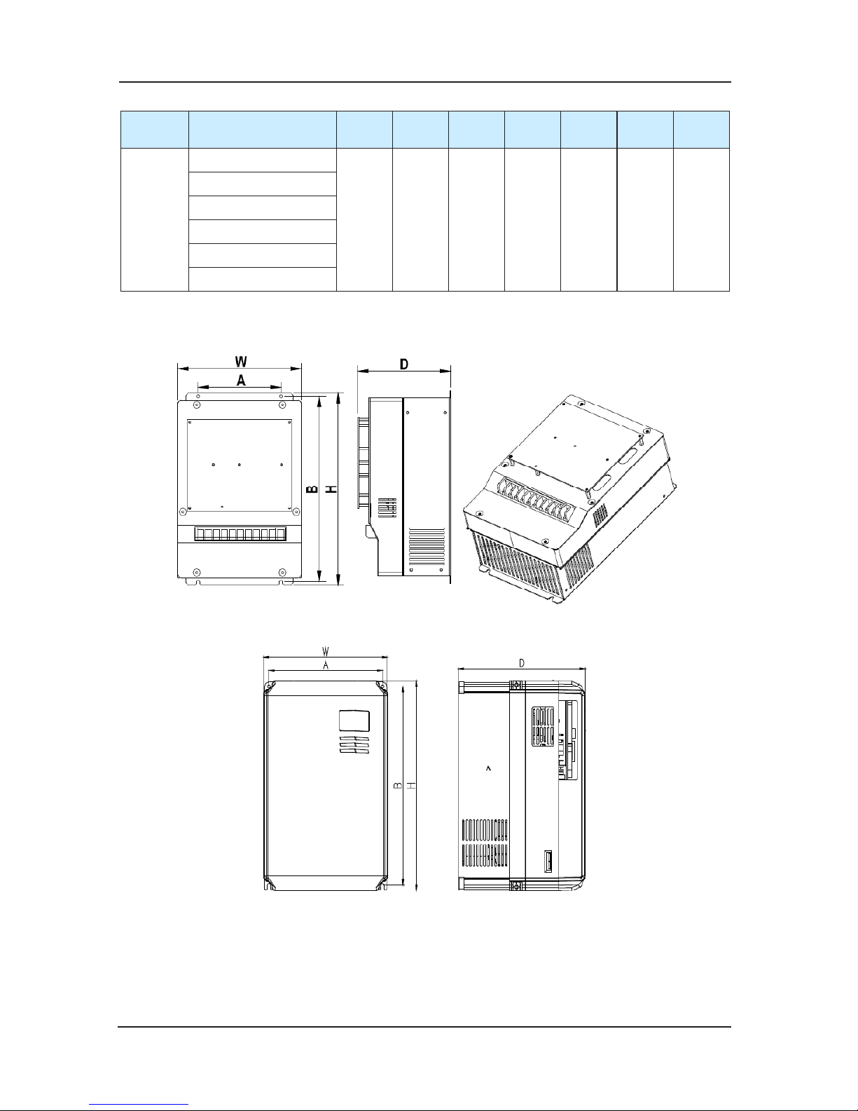
NICE3000 controller has three sizes of models: size-C, size-D and size-E, details are as the
following:
Structure
type
Model
A
(mm)
B
(mm)
H
(mm)W (mm)
D
(mm)
Hole
(mm)
G.W
(kg)
SIZE-C
NICE-L-A/B-2002
140 344 355 220 150 6.5 10
NICE-L-A/B-2003
NICE-L-A/B-4002
NICE-L-A/B-4003
NICE-L-A/B-4005
SIZE-D
220-NICE-L-A/B-4007
150
334.5
347.5
223 167.5
6.5
12
220-NICE-L-A/B-4011
220-NICE-L-A/B-4015
NICE-L-A/B-4007
NICE-L-A/B-4011
NICE-L-A/B-4015
220-NICE-L1-A/
B-4007
190 305 322 208 212 6 6.5
220-NICE-L1-A/
B-4011
220-NI
CE-L1-A/
B-4015
NICE-L1-A/B-4007
NICE-L1-A/B-4011
NICE-L1-A/B-4015
Page 26
Product Information NICE3000 User Manual
26
Structure
type
Model
A
(mm)
B
(mm)
H
(mm)W (mm)
D
(mm)
Hole
(mm)
G.W
(kg)
SIZE-E
220-NICE-L-A/B-4018
235 541.5 554.5 289.6 223 6.5 14.5
220-NICE-L-A/B-4022
220-NICE-L-A/B-4030
NICE-L-A/B-4018
NICE-L-A/B-4022
NICE-L-A/B-4030
Note: products with other power rank, such as higher than 37kw, due to little usage, we don’t
list here. If you need them, please contact our company.
Fig 2-4-1 size diagram of the controller
Fig 2-4-2 size D new Structure
Page 27
NICE3000 User Manual Product Information
27
2.5 Daily Maintenance of Controller
Since the inuence of ambient temperature, humidity, dust, and vibration, the components in
controller may become aging and wearing, which will give rise to the occurrence of potential
faults and reduce the life of controller. Therefore, it is quite necessary to do the work of daily
maintenance of controller.
The filter capacitor still has high voltage after the power supply to the controller is switched off, so
do not maintain or repair the controller until the bus voltage measured after 2 or 3 minutes with the
multi-meter. The voltage must be lower than 36V.
2.5.1 Daily Maintenance
Daily checking items:1)
Check if there is any abnormal noise during the running of motor;a)
Check if there is any vibration
of motor ;b)
Check if the installation environment of controller changes ;c)
Check if the cooling fan of controller works normally ;d)
Check if the controller is over heated.e)
Daily Cleaning:2)
Keep the controller in a clean status;a)
Clean the dust from the controller and prevent the dust especially the metal powder from b)
entering the controller;
Clean the oil dirt in the cooling fan of the co
ntroller.c)
2.5.2 Periodical Checking
Periodically check the places that are hardly checked during the running.
Periodical Checking Items1)
Check the ventilation channels and clean them periodically;b)
Check if the screws are loose;c)
Check if the controller is rusted;d)
Check if the input / output terminals has scratch marks;e)
Check the insulating in main circuit.f)
No te: Ins ulat ion tes t (us e 500 V
Me ga-O hm-M eter ) sho uld be d one separ atel y aft er
disconnecting the input power cables from the controller; or else, the controller will be
damaged. Do not use the Mega-Ohm-Meter to test the insulation of control circuits. Dielectric
strength test had been done at factory. Therefore, user need not do this test again.
Page 28
Product Information NICE3000 User Manual
28
Replacement of aging Parts2)
The wearing parts of controller mainly include the cooling fan and filtering electrolytic capacitor.
Their lifetime is closely related to the operating environment and maintenance.
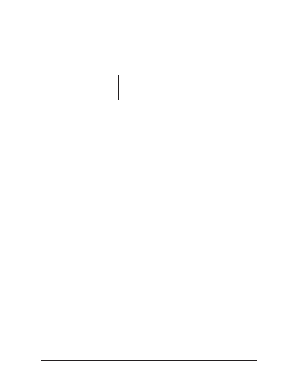
General lifetime as follows:
Component Lifetime
Fan 2 ~ 3 years
Electrolytic capacitor 4 ~ 5 years
Uses could determine when to replace them according to their working time.
Cooling fan1)
Possible damage causes: shaft bearing attrition and blade aging.
Criteria: no crack on fan blade, no abnormal vibration noise at start.
Filtering electrolytic capacitor2)
Possible damage causes: high ambient temperature, big pulsating current due to
frequent load
uctuation, electrolyte aging.
Criteria: no liquid leak, no protrusion of safety valve, electrostatic capacitance measurement,
and insulation resistance measurement.
2.5.3 Controller Storage
The following points must be noticed in controller storage:
It is recommended to store the controller in its original packing box.1)
Long-term storage will cause deterioration of electrolytic capacit
or. Therefore, controllers 2)
not in service for a long time must be powered for at least once within 2 years for testing
purpose, at least for 5 hours ; in the test , the input voltage must be boosted gradually with
voltage regulator to the rated value.
Page 29

3
Structure of the control system and the
component introduction
Page 30
Structure of the control system and the component introduction NICE3000 User Manual
30
Chapter 3 Structure of the control system and the
component introduction
3.1 Using Introduction of CTB
Car top board MCTC-CTB-A is the main control board of NICE 3000’s car . It is made up of
eight digital signal input terminals, one analog voltage signal input terminal, eight relay N.O.
output terminal, one N.C. relay output terminal, two digital signal input and output terminals
which can communi
cate with the command board CCB, CAN communication terminal with
MCB, communication terminal with car display board Modbus, and RS232 communication
mode which supports the communication with the computer. It’s of great function and is the
important transferring station of signal collection and signal outputting control in NICE 3000
integrated controller.
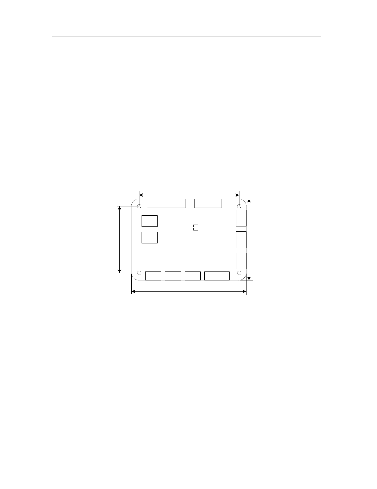
3.1.1 Appearance and size
CN4 CN 5
CN2 CN1 CN6 CN3
C
N1
0
C
N7
C
N8
S1
S2
162
152
125
115
CAN
RESET
Fig 3-1 Installing size of CTB
3.1.2 Introduction of installation and using
Installing method1)
Install it after the complete power failure of the lift;a)
Aim at four installing pores of car, and then use screwdriver to hold;b)
Link terminals and screw down.c)
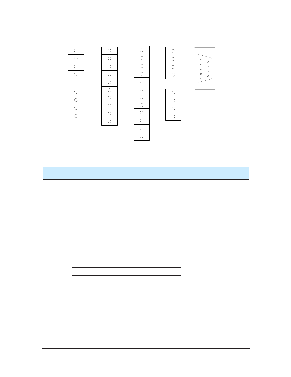
Definition of terminals is shown in Chart 9-2: 2)
Page 31
NICE3000 User Manual Structure of the control system and the component introduction
31
X1
X2
X3
X4
CN3
P24
P24
X5
X6
X7
X8
BM
B1
B2
B3
CM
C1
C2
C3
DM
D1
D2
CN4
24V
MOD
+
MOD
-
COM
CN1
24V
CAN
+
CAN
-
COM
CN2
A
AM
CN5
P24
Ai
M
CN6
CN7
Fig 3-2 Definition of CTB terminals
Explanation of controlling terminals’ function 3)
Type
Terminal
designation
Terminal name Functional explanation
Power
24V
(CN1、CN2
terminals)
Connect to +24V external power
source
Provide+24Vpower for whole
board as Operational Power
Supply
COM
(CN1、CN2
terminals)
Connect externally to common
port
P24
(other terminals)
+24V power supply
Common port of digital input
and analog input
Function digital input
X1 Font door beam screen
Photocoupler isolation,
unipolar
ity input
Input impedance:3.3KΩ
MCTC-CTB signal is valid when
inputting 24V power supply
X2 Back door beam screen
X3 Font door open limit
X4 Back door open limit
X5 Front door-close limit
X6 Back door-close limit
X7 Full load signal (100%)
X8 Over load signal (110%)
Analog input Ai-M Weighing signal input DC:0~10V
Page 32
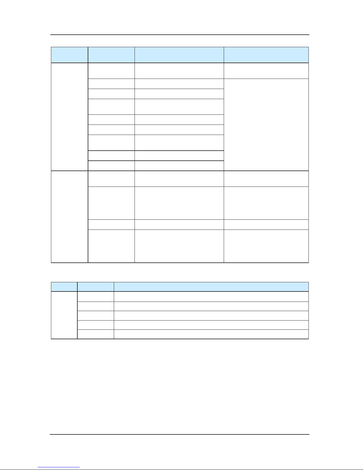
Structure of the control system and the component introduction NICE3000 User Manual
32
Type
Terminal
designation
Terminal name Functional explanation
Relay output
A-AM Car fan / illuminate controller
AC:250V,3ª
Or DC:30V,1A
B1-BM Front Door opening signal
DC:30V,1A
B2-BM Front Door closing signal
B3-BM
Door lock (Closed indicates the
door lock is smooth)
C1-CM Back Door opening signal
C2-CM Back Door closing signal
C3-CM
Door lock (Closed indicates the
door lock is smooth)
D1-DM Up arrival signal
D2-DM
Down arrival signal
communication
CAN+/CAN- CAN communication
Communicate with controller of
NICE3000
MOD+/MOD- Modbus communication
Communicate with Modbus
Caution: car MOD
communication has the same
connection with hall call.
Consult 9.3
CN10 RS232 communication Factory use.
CN7 CN8 Command board communication
Make the digital signal inputting
and outputting communication
with command board. Consult
9.2 t
he instruction of command
board.
Functional introduction of each dial-switch of CTB:4)
Name Dial card Functional Description
SW1
1 Use for Parallel connection, the car top board of No.2 parallel lift switches to “ON”.
2 Reserved
3 Reserved (Factory using)
4 Matching resistance of Modbus whole line terminal
5 Matching resistance of CAN whole line terminal
Cautions:
In order to protect communication signals from external disturbance, we advise to use 1)
STP for communication connection ,and do
the best not to disturb parallel;
It is better to use Shielded cable for signal wiring of communication;2)
Connect strictly according to terminal signal, and screw down.3)
Page 33
NICE3000 User Manual Structure of the control system and the component introduction
33
3.2 Using introduction of CCB
Command board CCB is matched with car top board CTB in NICE 3000 integrated controller.
Each command board comprises 24 input interfaces and 22 output interfaces, including 16 oor
buttons and 8 functional signals. Its function is to collect button instruction and output showing
light source. In order to meet 32 oors’ need, we adopt concatenation. And then through th
e
parallel, it can meet the needs of two commands inputting light output operation panels in the car.
3.2.1 Appearance and size
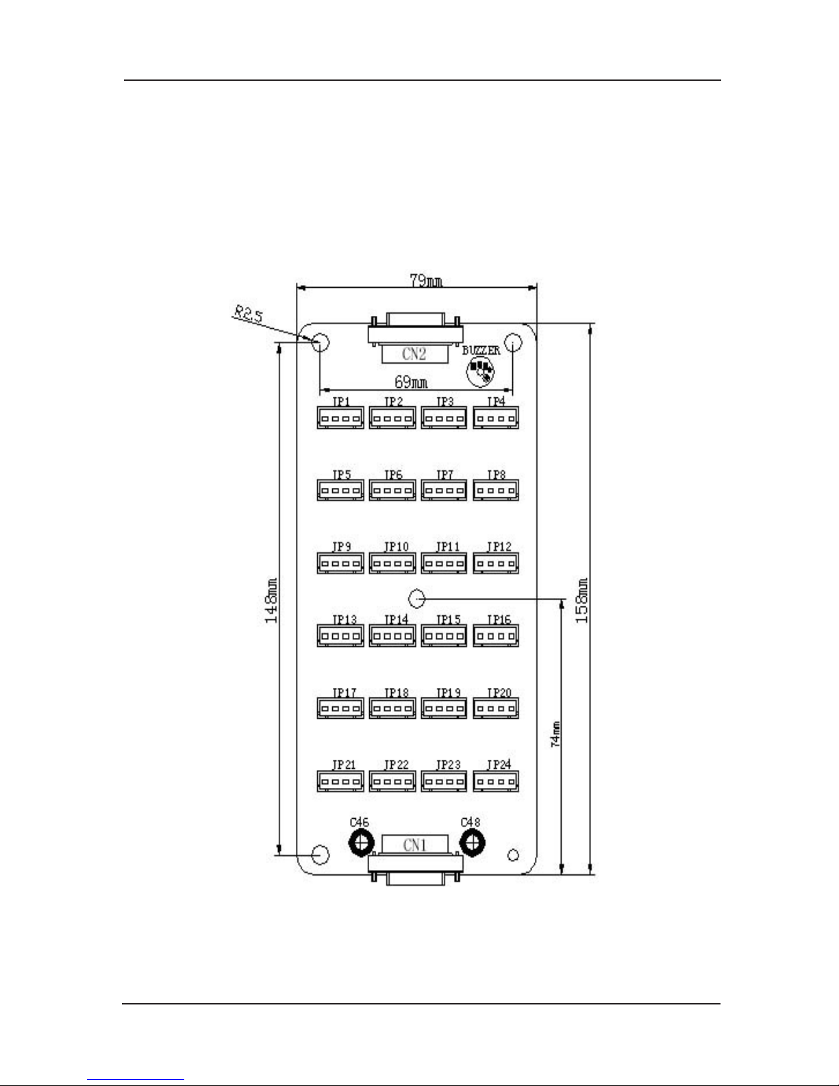
Fig 3-3 Installation size of CCB
Page 34
Structure of the control system and the component introduction NICE3000 User Manual
34
3.2.2 Introduction of installation and using
Installation mode1)
Install in the condition of power off;b)
Aim at four installing pores of car, and then use screwdriver to hold;c)
After checking the order of button connection and button plug, plug button switch into d)
instruction plate’s slot;
Connect to the car top board through terminals, and make sure that connection end is e)
instruction plate C
N2’s interface. If connection end is CN1, CTB or instruction plate
can be destroyed.
Definition of terminals’ interface 2)
A connection interface that adopts 9PIN parts of an apparatus is in the up and down end a)
of the instruction plate, can communicate with car top board, and make concatenation
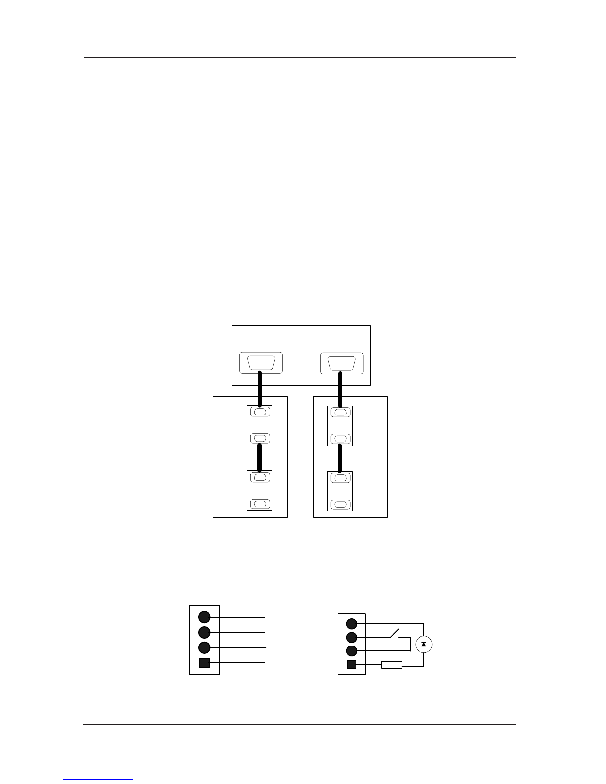
with two command boards. The concatenation relationship between car top board and
command board is show
n in Chart9-4:
Cn2
Cn1
Cn2
Cn1
Cn2
Cn1
Cn2
Cn1
MCT C-CTB-
A
CN7 CN8
car operation panel
sub-operating panel
Fig 3-4 Concatenation sketch between CTB and CCB
Definition of 4 PIN interfaceb)
Command board’s 4 PIN interface‘s definition of VER-A, VER-B, VER-0 edition is shown in
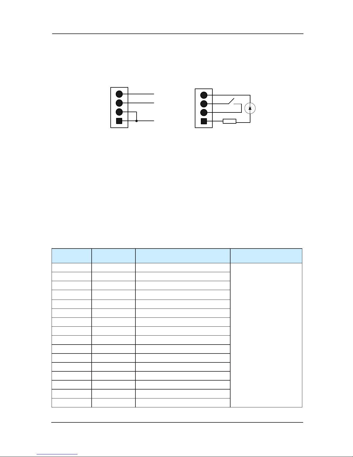
the following chart 9-5:
MP2
4
KEY-IN
KEY-
LED
1
3
4
2
GND
1
3
4
2
Fig 3-5 Command board’s 4 PIN interface‘s definition and external connection of VER-A,
VER-B, VER-0 edition
Page 35
NICE3000 User Manual Structure of the control system and the component introduction
35
When use these three command boards, users must pay attention to the wiring and the use of
buttons between MP24 and GND. Do not jump-out or it will damage the command board.
Command board’s 4 PIN interface‘s definition of VER-C edition is shown in the following
chart 9-6:
MP2
4
KEY-IN
KEY-
LED
1
3
4
2
1
3
4
2
Fig 3-6 Command board’s 4 PIN interface‘s definition and external connection of VER-C
edition
4 PIN interface of VER-C edition has been modified. Getting rid of GND means the avoidance
of the user’s miss-operation to cause the damage of the board due to the short circuit. The
meaning of signals in Chart 9-5 and Chart 9-6: MP24 (24V Power), KEY-IN (Button input
signal), KEY-LED (Button light output),
GND (0V).
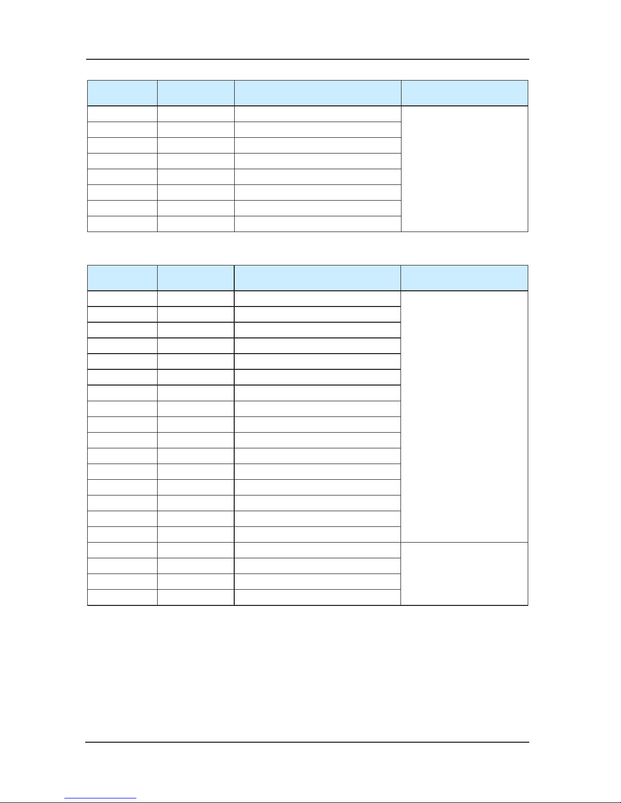
Definition of input and output interface 3)
There are 24 instruction inputs, 21 light outputs in each of CCB. When the number of oor is
over 16 and the command board adopts concatenation, the command board 2 only uses input
16 and output 16 (only use for oor input and corresponding light output) .Definition according
to the order is listed as follows :
Command inputa)
Sequence
number(n)
Corresponding
interface
Definition Instruction
1 JP1 Floor 1button input
Input signal corresponds to
oor(16+n) button input for
command board 2
2 JP2 Floor 2 button input
3 JP3 Floor 3 button input
4 JP4 Floor 4 button input
5 JP5 Floor 5 button input
6 JP6 Floor 6 button input
7 JP7 Floor 7 button input
8 JP8 Floor 8 button input
9 JP9 Floor 9 button input
10 JP10 Floor 10 button input
11 JP11 Floor 11 button
input
12 JP12 Floor 12 button input
13 JP13 Floor 13 button input
14 JP14 Floor 14 button input
15 JP15 Floor 15 button input
16 JP16 Floor 16 button input
Page 36
Structure of the control system and the component introduction NICE3000 User Manual
36
Sequence
number(n)
Corresponding
interface
Definition Instruction
17 JP17 Door opening button input
Invalid for command board 2
18 JP18 Door closed button input
19 JP19 Door opening delay button input
20 JP20 Nonstop button input
21 JP21 Motorman button input
22 JP22 Reversing direction button input
23 JP23 Running independently button input
24 JP24 Fireman input
Light output:b)
sequence
number(n)
corresponding
interface
definition explanation
1 JP1 Floor 1show output
Input signal corresponds
to oor(16+n) display for
command board 2
2 JP2 Floor 2 show output
3 JP3 Floor 3 show output
4 JP4 Floor 4 show output
5 JP5 Floor 5 show output
6 JP6 Floor 6 show output
7 JP7 Floor 7 show output
8 JP8 Floor 8 show output
9 JP9 Floor 9 show output
10 JP10 Floor 10 show output
11 JP11 Floor 11 show output
12 JP12 Floor
12 show output
13 JP13 Floor 13 show output
14 JP14 Floor 14 show output
15 JP15 Floor 15 show output
16 JP16 Floor 16 show output
17 JP17 Door opening show output
I
nvalid for command board 2
18 JP18 Door closed show output
19 JP19 Door opening delay show output
20 JP20 Nonstop show output
Cautions:
In order to protect communication signals from external disturbance, we advise to use
STP for communication connection;
Con
nect strictly according to terminal signal, and insert the button firmly;
The two terminals of the command board are the same interface apparatus, so when in
parallel connection of the command board, pay attention not to wrongly connect.
Page 37
NICE3000 User Manual Structure of the control system and the component introduction
37
3.3 Direction for use of HCB
HCB is one of important interfaces that are used to connect NICE3000 controller to users. HCB
can accept user’s call-up and show lift’s current oor, running direction and so on. At the
same time HCB can be used for car cage displaying panel (the detail is shown in section 9.3.3).
HCB is diversified. In order to meet all kinds of needs, it is classified into several differ
ent forms,
whose types are: MCTC-HCB-B no display output hall call; MCTC-HCB-F vertical dot-matrix
hall call; MCTC-HCB-H and MCTC-HCB-J. horizontal dot-matrix hall call. We will only introduce
the using method and attention items of MCTC-HCB-H, MCTC-HCB-F, and MCTC-HCB-J.
3.3.1 MCTC-HCB-B
The hall call board HCB is one of the main interfaces between the NICE 3000 controller and
users
in order to meet
the needs of different customers and enrich the product range, we develop the
non-display hall call board – MCTC-HCB-B
3.3.1.1External view
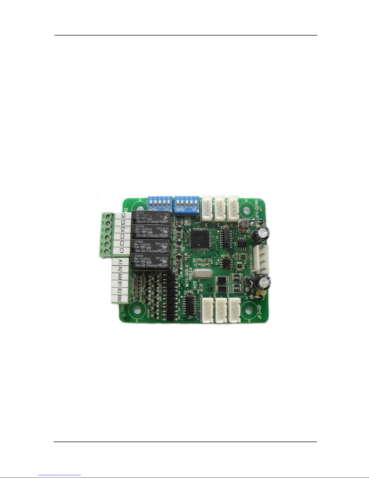
Fig 3-7 External view of MCTC-HCB-B
Page 38
Structure of the control system and the component introduction NICE3000 User Manual
38
3.3.1.2 Appearance and measurement
CN1
89S52
70.2mm
56.2mm
mm
62.5mm
JP1
JP3
JP5
JP2
JP4
JP6
CN2
K1K2K3K4
S2
S1
A1A2AMB2
B1
BM
F5
TEST
BL1
BL2
IMPE
F4
F3
F2
F1
F0
C1
C2 C3 C4 C5 C6
84.0
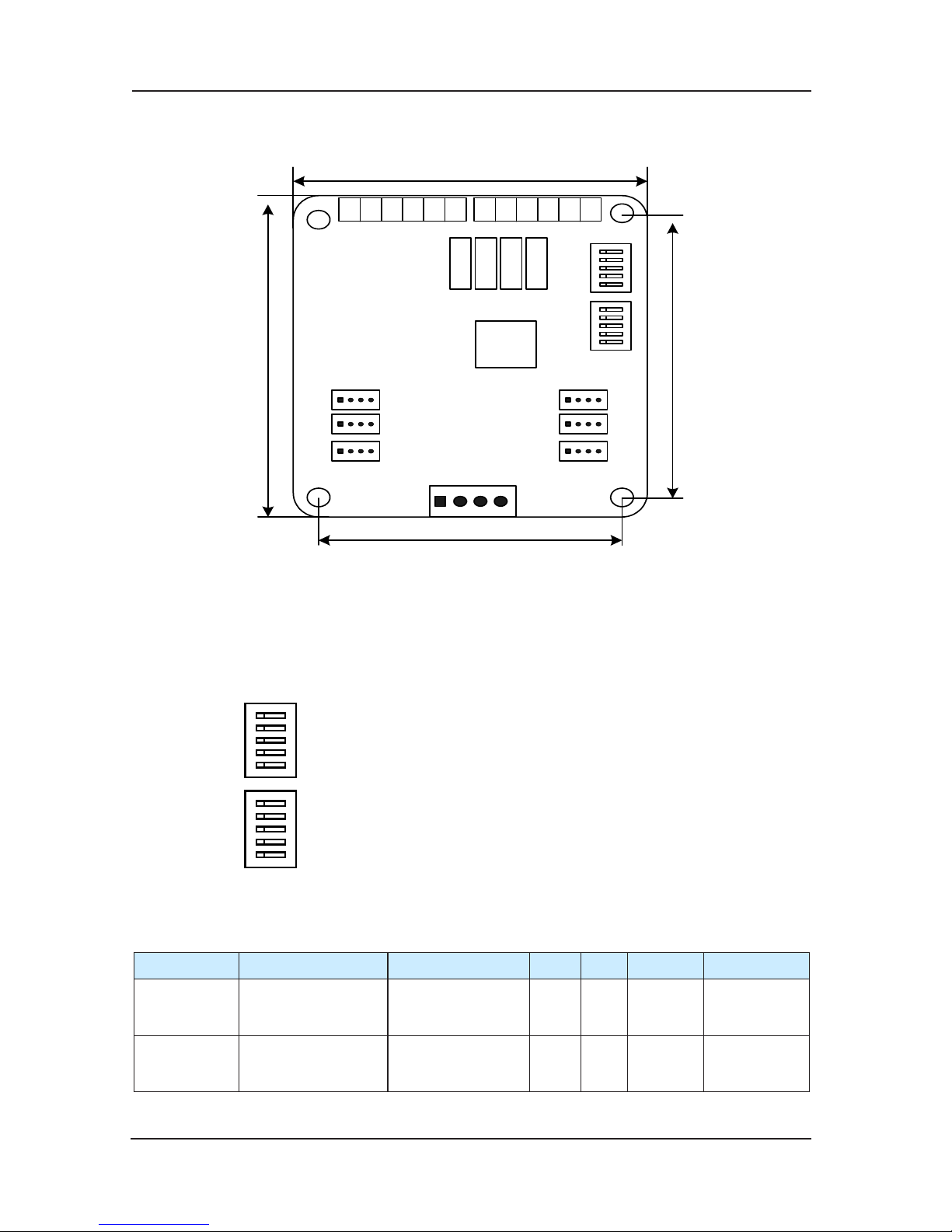
Fig 3-8 Installation measurement of MCTC-HCB-B
3.3.1.3 Installation and using introduction
Dial-code setting1)
3.3.1.4 Function specification
S1.1~S1.5 S2.1 S2.2 S2.3 S2.4 S2.5
HCB-B
Floor address
setting,range:0~31
MOD bus
terminal matching
resistance setting
OFF ON Detection
Floor address
setting
HPB
Floor address
setting,range:0~31
MOD bus
terminal matching
resistance setting
ON OFF Detection
Floor address
setting
S2
S1
F5
TEST
BL1
BL2
IMPE
F4
F3
F2
F1
F0
F5--- oor 5
TEST--- testing dial-code
BAOLIU1---reserved 1, used for function select
BAOLIU2----reserved 2, used for function select
IMPE--- matched resistance
F4---oor 4
F3---oor 3
F2--- Floor 2/voice station report oor selection 2
F1--- Floor 1/voice station report oor selection 1
F0--- Floor 0/voice station report oor selection 0
Page 39
NICE3000 User Manual Structure of the control system and the component introduction
39
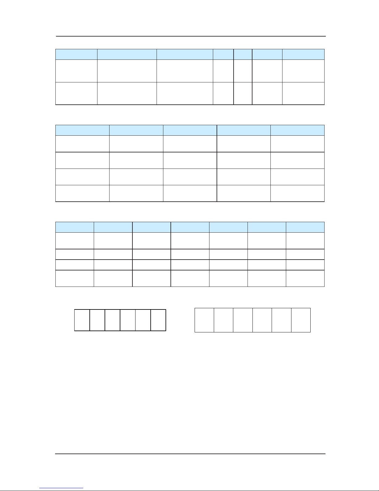
S1.1~S1.5 S2.1 S2.2 S2.3 S2.4 S2.5
7 segment
code function
Floor address
setting,range:0~31
MOD bus
terminal matching
resistance setting
OFF OFF Detection
Floor address
setting
Voice station
report
S1.1~S1.3oor
setting
S1.4,S1.5
MOD-bus
terminal matching
resistance setting
ON ON Detection Reserved
Table 1
K1 K2 K3 K4
HCB-B Up arrival lamp
Down arrival
lamp
Up arrival gong
Down arrival
gong
HPB
Overload/full-
load
Reserved Up indicate Down indicate
7 segment
function
G
Overload/full
load
Up indicate Down indicate
Voice station
report
Overload/full
load
Arrival output Up output Down output
Table 2
C1 C2 C3 C4 C5 C6
Common
terminal
BM BM BM BM BM BM
HPB, F0 F1 F2 F3 F4 负号
7 segment A B C D E F
Voice station
report
Floor binary
bit0
Floor binary
bit1
Floor binary
bit2
Floor binary
bit3
Reserved Reserved
Table 3 open collector output binary oor display
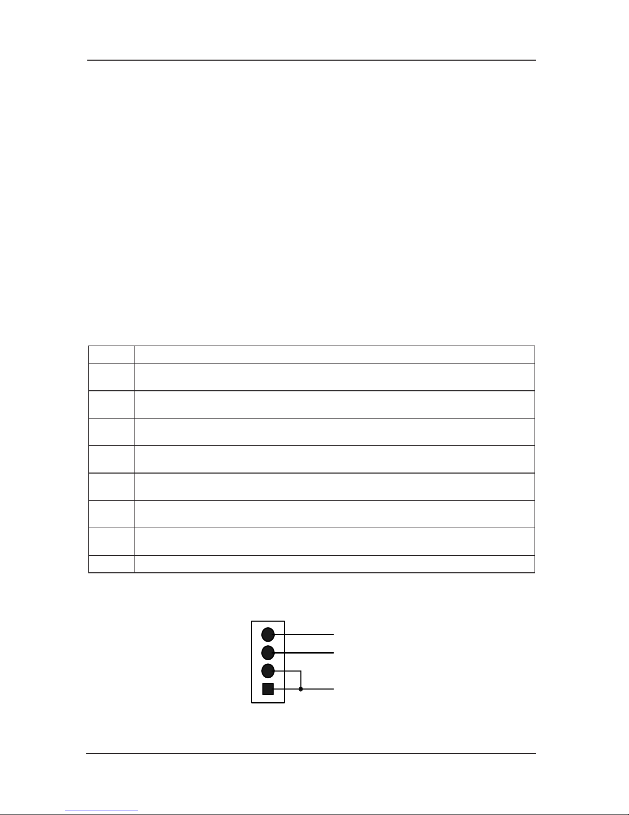
CN2
A1A2AMB2 B1BM
123456
C1
C2 C3 C4 C5 C6
Fig3-9 CN2 terminal definition Fig 3-10 CN3 terminal definition
HCB-B function 1)
Totally compatible for the original HCB-B function
The definitions of the dial-code switch bits are as the table 1.
The oor address is the valid oors (standard as the leveling plate) increased down to up, and
it has no relations with the actual oor numbers.
For instance, if a building has 2 oor basem
ent, 10 oors above the earth, and the 3rd and 4th
oor are the non-service oor, then the oor address setting is: the 2nd oor of basement set as
1; the 1st oor of the basement set as 2; the 1st oor above the earth set as 3, 2nd oor above
set as 4, and if there is leveling plate in the 3rd and 4th oor, then set them as 5,6. From the
Page 40
Structure of the control system and the component introduction NICE3000 User Manual
40
5th oor, successively set as 7,8,9..., and if there is no plate in the 3rd and 4th oors, from the
5th oor, successively set as 5,6,7....
Input part
Plug the wiring interface of the lift-locked and fire-emergency switches into the socket of JP1
and JP2, plug the general up/down buttons wiring interface into the JP3 and JP4,, and plug the
disabled up/down buttons wiring interfaces into the JP5 a
nd JP6.
Plug the wiring interface of the MOD-bus communication cable into CN1.
Remark:
Do not set the oor address of the hall call board as 0;a)
The STP is re commended for the comm unication wiri ng to avoid the external b)
interference to the communication signal;
It’s recommended to use the shielded cable as the communication signal wire; c)
Please wiring firmly according to the terminal symbol;
d)
Terminal input and button output
Terminal Function
JP1 The pin 2 and 3 of lift-locked switch interface are the pin of switching value, the pine 4 is
the lift-locked lamp output.
JP2 Fire-emergency switch interface, the pin 2 and 3 are the switching value wiring pin, pin 4
is the fire-emergency indicator output
JP3 General up call button interface, the pin 2 and 3 are the switching value wiring pin, the pin
1 and 4 are the power wirin
g pin used for the control of button lamp.
JP4 General down call button interface, the pin 2 and 3 are the switching value wiring pin, the
pin 1 and 4 are the power wiring pin used for the control of button lamp.
JP5 Disabled up call button interface, the pin 2 and 3 are the switching value wiring pin, the
pin 1 and 4 are the power wiring pin used for the control of button lamp.
JP6 Disabled down call b
utton interface, the pin 2 and 3 are the switching value wiring pin, the
pin 1 and 4 are the power wiring pin used for the control of button lamp.
CN1 MOD-bus communication and power wire terminal, 4PIN interface the pin 2 and 3 are the
pin of MOD-bus communication wire, the pin 1 and 4 are the power wiring pin.
CN2 Relay output, see Fig.3-9-3 for the definition details
Table 4 I/O Terminal definition
J
P1-JP6 are 4PIN interfaces. The pin details refer to Fig. 3-11
MP 2 4
KE Y- I N
KE Y- LE D
1
3
4
2
Fig 3-11 4PIN interface
Relay output
Page 41
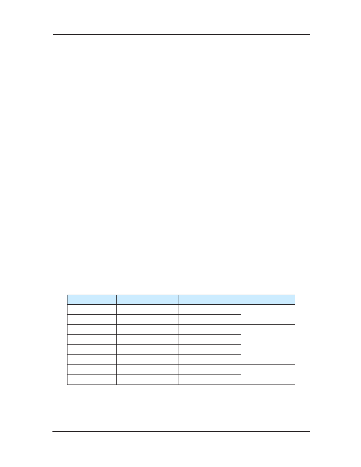
NICE3000 User Manual Structure of the control system and the component introduction
41
The no-display hall call board designed with 4 relay output, namely the K1、K2、K3 and K4,
output by CN2 terminal. Please refer to the fig 3-9-3 for details
HPB、LCD function 2)
Realization of HPB and LCD function a)
The dial switch bit definitions see Table 1
Terminal I/O definition b)
The input and communication interface definitions are same as the one of HCB-B, fig
3-9-3 for the CN2 terminal ,
see Table 2 for detailed functions and output interface.
See the Tanle 3 for the open collector output binary oor display.
segment code function 3)
The 7 segment function is applied to the freight elevator reformation, currently concern 1 Nixie
tube, and with specialized program it can be expanded.
Dial switch settings. a)
See Table 1 for the dial switch bit definitions
See Table 2 for the Input an
d communication interface
Output definition
Open collector output
Voice station report function 4)
Dial switch settings a)
See Table 1 for dial switch bit definition
See Table 2 for the input and communication interface.
Settings of F2,F2,F0
Based on the settings of F0-F2, the voice reporter will give report for different oors.
F2 F1 F0
0 0 0 0,1-10
1 0 0
0 0 1 -1,0,1-10
0 1 0
1 0 1
1 1 0
0 1 1 -2,-1,0,1-10
1 1 1
Input and communication interface.b)
Communication interface as Table 1
The voice reporter has no input signal, so just neglect the JP1-JP6.
Page 42
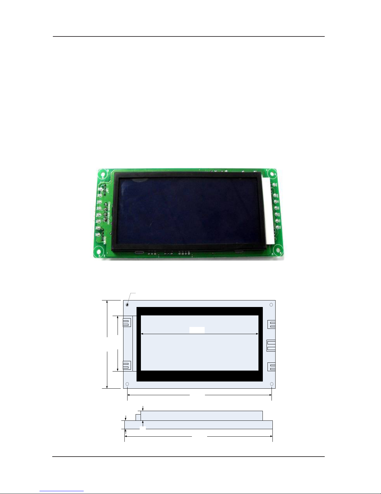
Structure of the control system and the component introduction NICE3000 User Manual
42
The open collector output as the Table 3
3.3.2 MCTC-HCB-D1
MCTC-HCB-D1 is designed on the basis of our company’s general dot-matrix, it’s adopts
the LCD segment display mode to display the up/down indicate arrows, floor signals and
elevator errors, over-load, inspection, fire-emergency 4 states.
The segment LCD display promote the rank of the hall call board; the rich display interface
display the
real-time elevator error, over-load, inspection, fire-emergency state; together
with the buzzer alarm, and the new MCU platform make the software design more various,
convenient for the customized communication protocol expansion. The backlight become dark
to save the power when the elevator stop for 1 minute.
Object photo1)
Fig 3-12
Size 2)
116mm
70mm
146mm
52mm
Ø3.5mm
10mm
10mm
158mm
Fig 3-3-7 158*70*20(mm)
Page 43
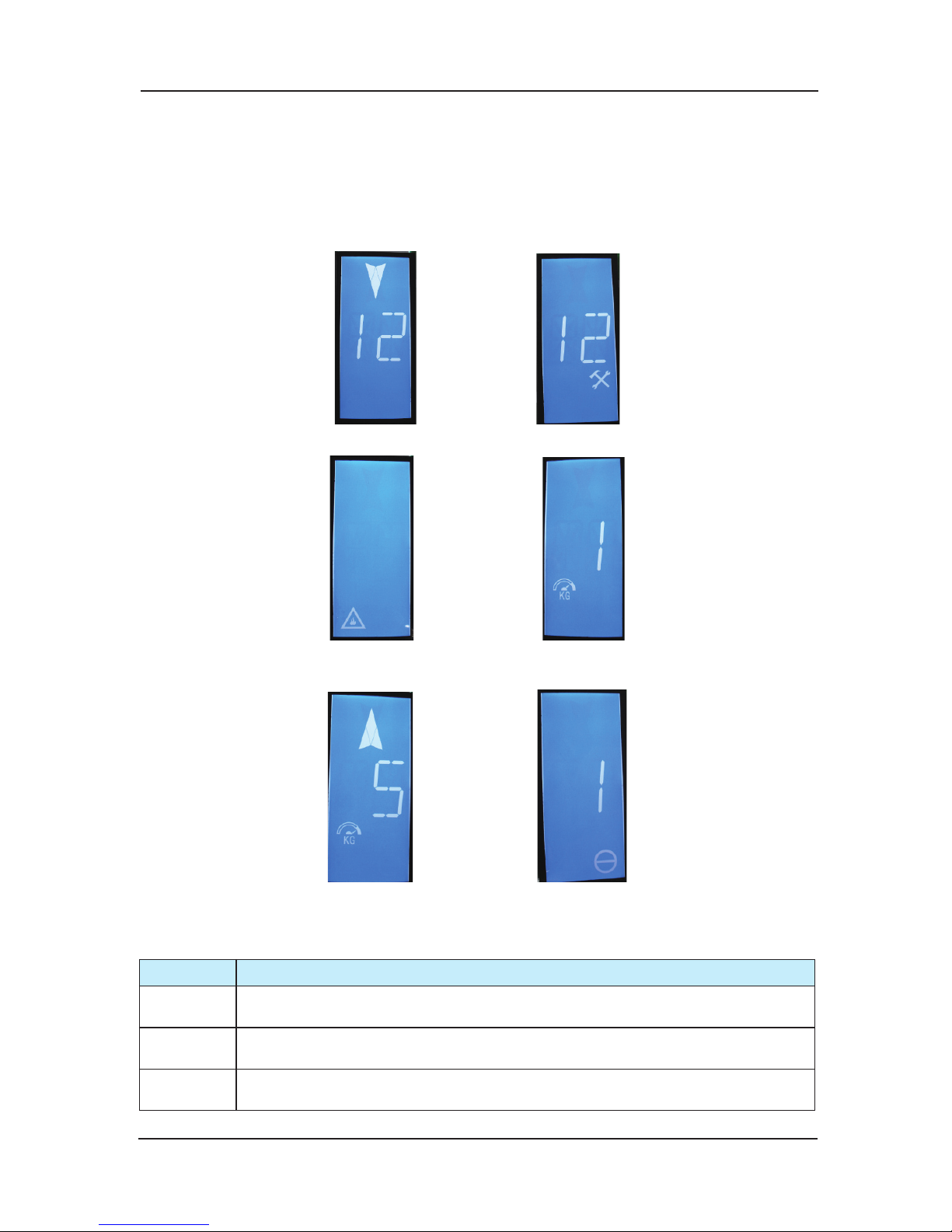
NICE3000 User Manual Structure of the control system and the component introduction
43
Name designation and model 3)
CTC is the short name of Suzhou Monarch Control Technology Co., Ltd, the HCB is the hall, car
display communication board, D means the segment LCD display, 1 means that this is the fi rst
kind of segment LCD hall call board, more display board of this series will be added follow-up.
Main function 4)
(1) Floor arrow display 2) Inspection display
(3) Fire-emergency state display:
the backlight display the fi re-control mark.
(5) Over-load display (6) Error display
Terminal specifi cation and electric wiring diagram 5)
Terminal Function
J1
Interface of lift-locked switch,2、3 are the switch value wiring pin,4 is the up
arrival light output
J2
Interface of fi re-control switch,2、3 are the switch value wiring pin,4 is the down
arrival light output
J3
Interface of up call button, 2、3 are the input switch value wiring pin,1、4 are the
power wiring pin,used to control button light
(4) Full display
Page 44
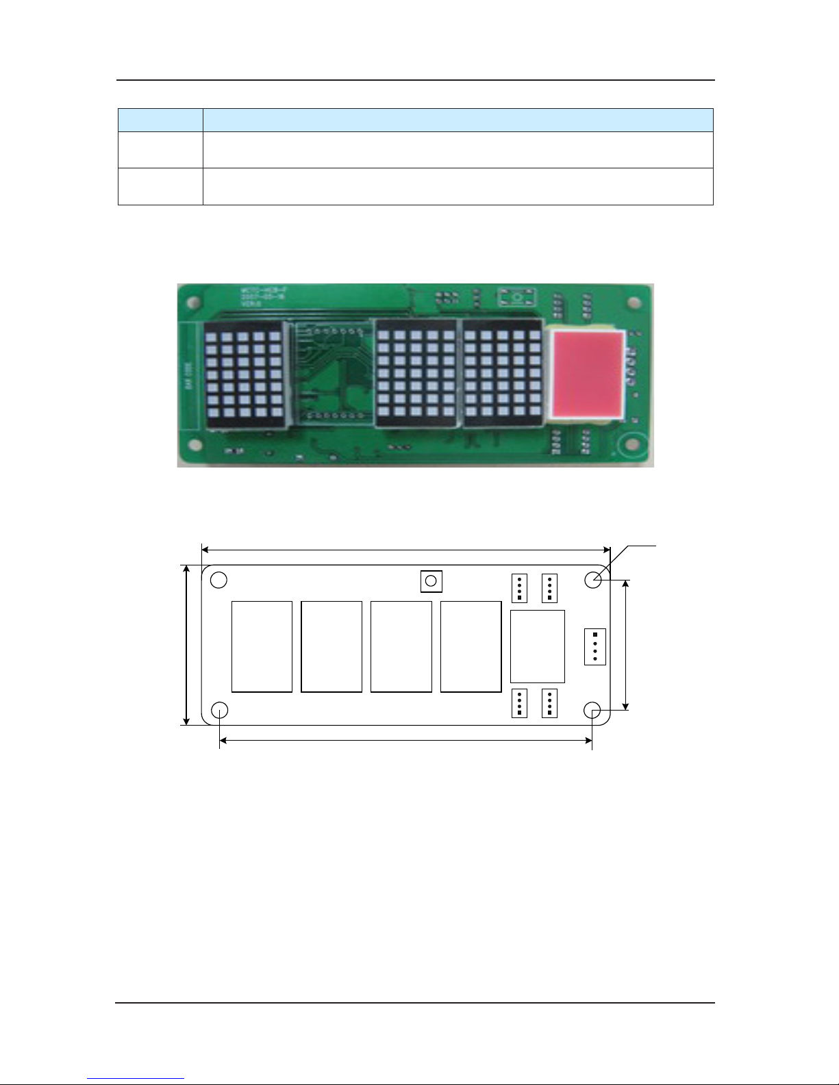
Structure of the control system and the component introduction NICE3000 User Manual
44
Terminal Function
J4
Interface of down call button, 2、3 are the input switch value wiring pin,1、4 are
the power wiring pin,used to control button light
J5
Mod-bus communication and power wire terminal,4PIN interface,2、3 are Modbus communication wire pin,1、4 are power wiring pin.
J1~J4 are button interface,details as the following:
Direction for use of MCTC-HCB-F
Product Photo of MCTC-HCB-F
Appearance and size (Shown as Fig 3-13)1)
70m
m
144mm
134mm
56mm
R2.5mm
V
1
V
2
V
3
V
4
D
4
S1
JP1
JP2
JP3
JP4
CN1
MCTC-HCB-F
Fig 3-13 Installation size of MCTC-HCB-F
Direction for installation and using2)
Floor address setting and installation modea)
Floor address setting: Press button S1 it will show the setting oor, and release the button for
4s it will return to show the current oor of the car cage. If you keep pressing the button for
more than 4s, it will get into the state of resetting the oor. Each time you pres
s the button, it
will add 1 to the number of the oor. If you keep pressing the button S1, the information of the
oor will add 1 continuously and the maximum setting value is 40. If there’s no pressing in the
continuous 4s, it will store the information of the oor where the displaying panel is in, and twice
shinning of the oor information indicates the successful storage. After 4s it will retur
n to display
the current oor where the car cage is in.
Page 45
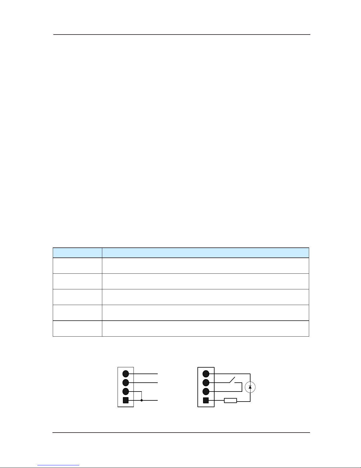
NICE3000 User Manual Structure of the control system and the component introduction
45
If the oor information setting is 0, it is car display panel;
The oor address is valid oor number (based on the leveling plate), increasing from the bottom
to the top and not related to the actual oor number.
For example: One building has two oors underground, and 10 oors above. Among theses,
Floor 3 and Floor 4 are service oors. So the setting of the dial switch’s oor address is as
follows:
The second floor underground is setting as 1, the first floor underground is setting
as 2, and first oor above the ground is setting as 3, and the second oor above the ground
is setting as 4. If there’s leveling plate between the third oor and the fourth oor, they are
setting separately as 5 and 6, meanwhile, the oors above the fifth oor are setting as 7, 8, 9…;
if there’s no leveling oor be
tween the third oor and the fourth oor, jump through it, and the
oors above the fifth oor are setting as 5, 6, 7….
Plug connection port of locked lift switch and fire switch separately into JP1 and JP2, and plug
connection port of button of up running and down running separately into JP3 and JP4.
Plug connection port used for Mod-bus communication into CN1.
Cautions:
Do not set hall call oor addres
s as 0;
In order to protect communication signals from external disturbance, we advise to use
STP for communication connection;
It is better to use Shielded cable for signal line of communication;
Connect strictly according to terminal signal, and screw down
Definition of input and outputb)
Terminal Name Function Definition
JP1 Switch Interface of locked lift, pin 2 、3 are switch connection pins, pin 4 is lift
lock indicator output
JP2 Switch Interface of fire fighting , pin 2 、3 are switch connection pins, pin 4 is
lift lock indicator output
JP3 Calling button interface of up running , pin 2 、3 are switch connection pins,
pin 1 、4 are power supply pins, for controlling button light
JP4 Call
ing button interface of down running , pin 2 、3 are switch connection pins,
pin 1 、4 are power connection pins, for controlling button light
CN1 Use for communicating with Modbus , pin 2、3 of 4Pin interface are for
communication, pin 1、4 are for power connection
The specific definition of 4 PIN is shown in Fig 3-14. The means of marks in the chart: MP24
(24V Power), KEY-IN (Button input signal), KEY-L
ED (Button light output), GND (0V).
MP 2
4
KEY-IN
KEY-
LED
1
3
4
2
1
3
4
2
Fig 3-14 Interfaces’ definition and external connection method of 4 PIN
Page 46
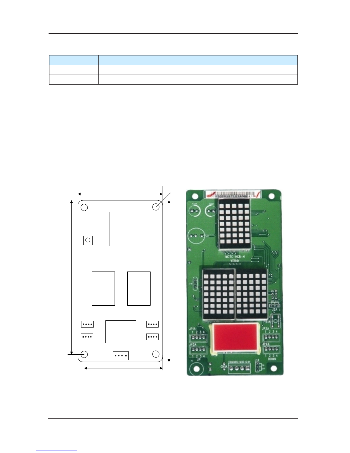
Structure of the control system and the component introduction NICE3000 User Manual
46
Instruction of plugs3)
Plug Name Function Definition
JP1 Setting of matched resistance to the terminal of MOD main line
JP2 Testing terminal, setting as “OFF” in application
J1 setting: Set the matched resistance to the terminal according to the actual needs. Generally
it’s only needed to set the J1 plug with the oor address 1 as “ON”. Other oors needn’t
set, which means “OFF”.
Note: Dot-matrix V4 is reserved in the normal c
ondition. When the users non-standard need
three dot-matrixes to display the oors, it will add this dot-matrix;
Inspection: When the lift is in inspection running, hall displaying panel V2, V3 scrolling display
“INS” and the current oor car located.
3.3.4 Direction for use of MCTC-HCB-H
Appearance and size (Shown as Fig 3-15)1)
56m
D1
JP3
JP4
CN1
JP1
JP2
R2.5m
m
70m
m
144m
m
134m
m
V1
V2
MCTC-HCB-
H
S1
V3
Fig 3-15 Installation size of MCTC-HCB-H
MCTC-HCB-H is the advanced product of MCTC-HCB-A. It possesses all the function of
MCTC-HCB-A, and optimizes the hardware: The setting of oor is changed from the dialing
code setting to the button setting.
Page 47
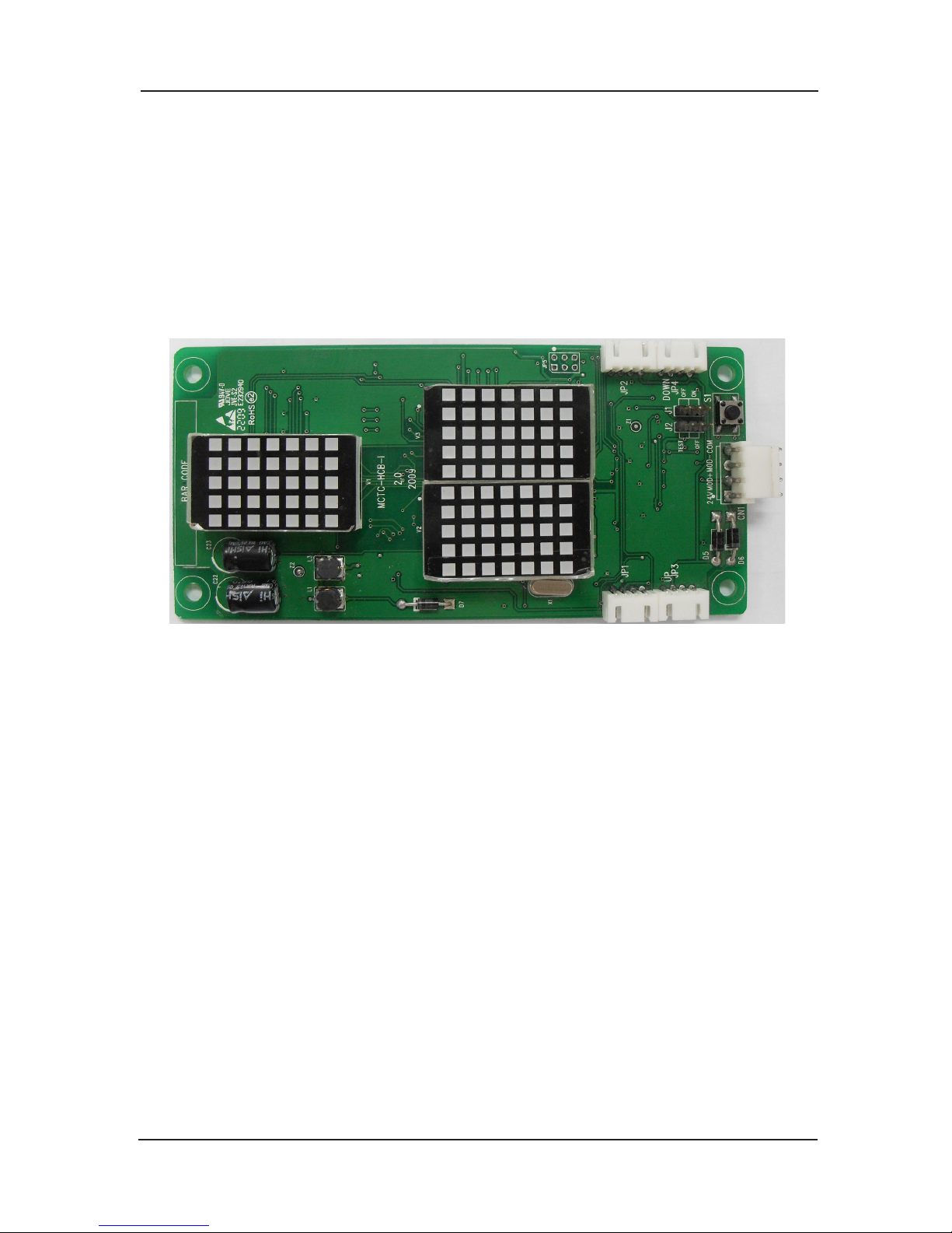
NICE3000 User Manual Structure of the control system and the component introduction
47
Direction for installation and using 2)
The floor addresses setting and installation mode, input and output definition, and plug
definition are all the same with MCTC-HCB-F; there are only V1, V2 and V3 three dot-matrixes
in the dot-matrix displaying of MCTC-HCB-H, without V4 comparing with MCTC-HCB-F. Others
are all the same with MCTC-HCB-F. Details are listed in section 9.3.2.
3.3.5 MCTC-HCB-I
MC
TC-HCB-I is a vertical oor unit display board (thickness only 15mm).
Object photo 1)
Fig 3-16 MCTC-HCB-I photo
Page 48
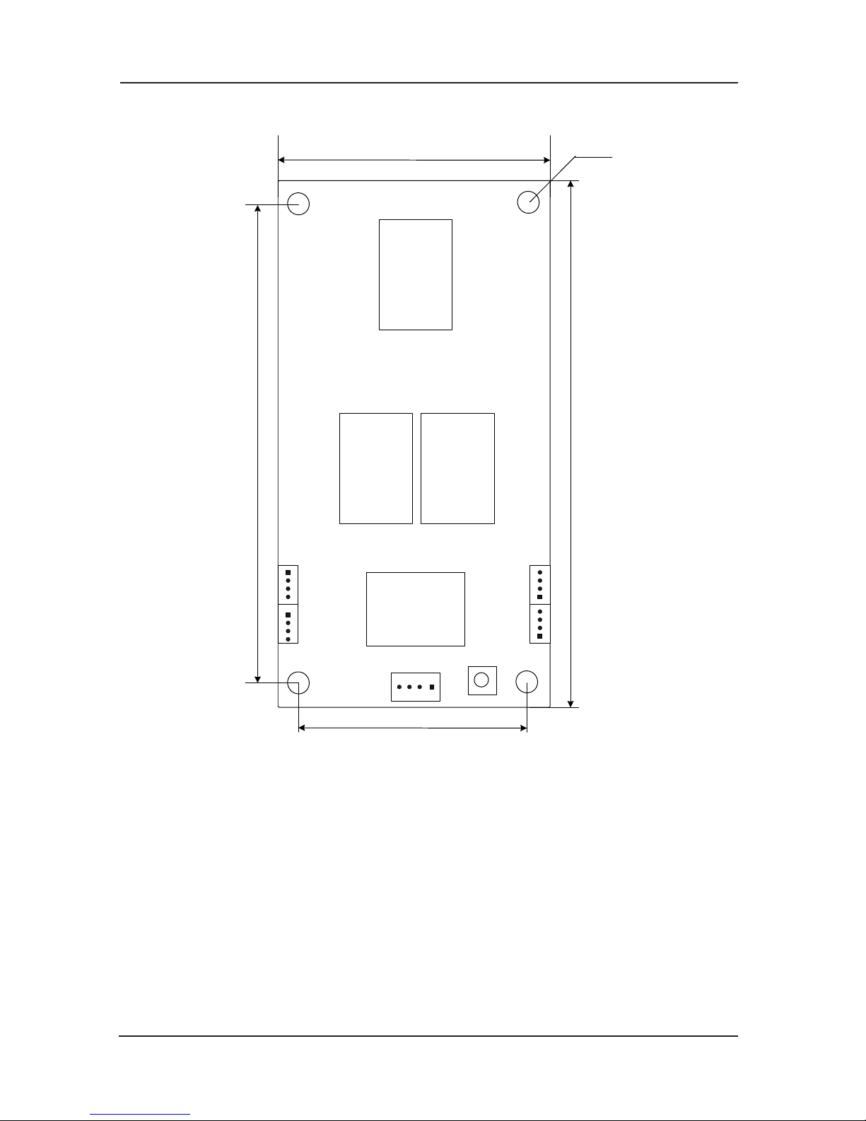
Structure of the control system and the component introduction NICE3000 User Manual
48
Size 2)
R2.5mm
70mm
V1
56mm
D1
JP3
JP4
CN1
JP1
JP2
144mm
134mm
V2
MCTC-HCB-I
S1
V3
Fig 3-17 MCTC-HCB-I install size
Function introduction 3)
This is the slim type design of MCTC-HCB-H, and with the same function as MCTC-HCB-H.
The high light red dot-matrix, a 5*7 dot-matrix display the run direction, two 5*7 dot-matrix
display the high and low bit of oor information respectively.
Output function:
4 output points, namely the up button light output, down button light output, up
arrival light
output and down arrival light output.
Input function:
4 input points, namely the lift-locked input, fire-control input, up call input and down call input.
Page 49
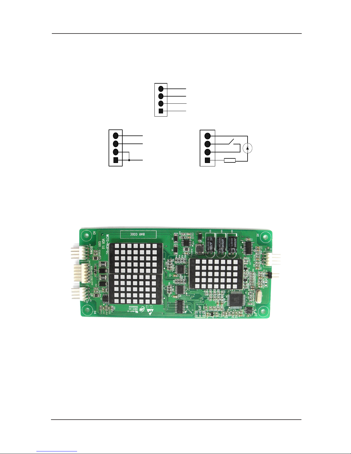
NICE3000 User Manual Structure of the control system and the component introduction
49
Floor address settings:
Button stroe, there is storing buttons on the board.
Power supply and communication input terminal (CN1):
White, horizontal blocks with 3.96 gap distance, user need to prepare the terminal head.
GND
MP 2 4
1
3
4
2
MO D +
MO D -
Ordinary button input terminal (JP1-6)
MP 2 4
KEY- I N
KEY- L ED
1
3
4
2
1
3
4
2
1 and 2 are 24V;3 is button input terminal;4 is button light output
3.3.6 MCTC-HCB-N
In order to meet the customer needs for the thin display board, Monarch developed a ultrathin
display board with a thickness of 10mm, see Fig 3-9-15 for the appearance.
Product photo 1)
Fig 3-9-15 MCTC-HCB-N
Page 50
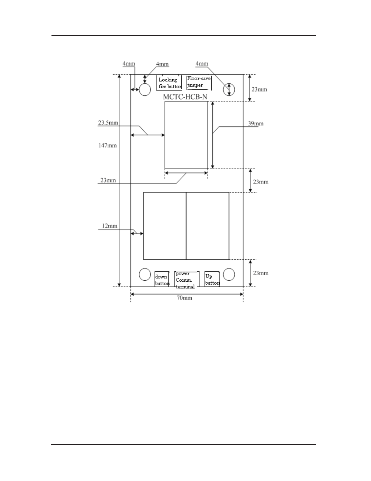
Structure of the control system and the component introduction NICE3000 User Manual
50
Size 2)
146*70*10(mm)
Fig 3-186 MCTC-HCB-N install size
Function specification 3)
Identify the oor storing by a jumper J1, When the J1 is short circuit, the call buttons JP2 and
JP3 were changed to be the AS buttons which used to modify the store oor; the jumper has
the call function only when it is not short circuit. Unfix the jumper hat to store the oor and no
need for the lighting piece display. The
Inspection and Full state are all display on the dot-
matrix.. JP1 lift-locked and fire-control signal input.
Page 51
NICE3000 User Manual Structure of the control system and the component introduction
51
call button is 4PIN,examine form the front, from left to right is:
Name Meaning
1 Button switch
2 Button switch
3 Button light
4 Button light
Power supply communication terminal is 6PIN,examine from the front, from left to the right is:
Name Meaning
1 None
2 None
3 MOD+
4 MOD-
5 COM
6 +24V
4PIN detailed meaning as the following, put the terminals and the oor storing contact pin on
the upper side of the board.
Name Meaning
1 Fire-control input
2 Fire-control input
3 Lift-locked input
4 Lift-locked input
3.3.7 MCTC-HCB-K
In order to meet the daily-increased customer needs for individuality, we design this unique car
LCD display product which adopts 320x240 pixel, 5.7 inch interface and LED backlight screen.
User can select his favorite display interface through the computer. After select the display
interface
, user can import the company logo to display on a certain place, and user can select
the type-face of oor display, time display and different display arrowheads etc.
The individuality is characterizing the MCTC-HCB-K; users only need to click the mouse on the
computer to realize the “unique” display effects.
The design of backlight auto on/off , automatically turn off the backlight if there is n
o landing
and opening signals within 1 minute, and also turn on the backlight as soon as the signals are
given. It can prolong the life-cycle of the LCD as well as the high efficiency.
Page 52
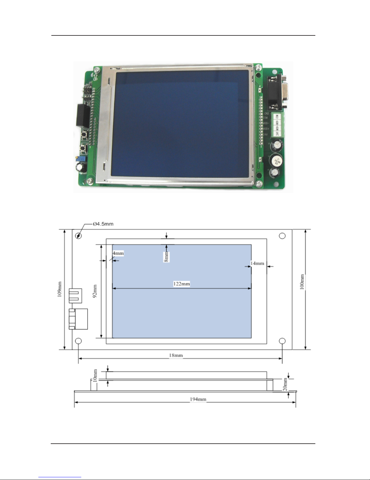
Structure of the control system and the component introduction NICE3000 User Manual
52
Product Photo 1)
Fig 3-19 MCTC-HCB-K photo
Size 2)
Fig 3-20 MCTC-HCB-K install size
Page 53
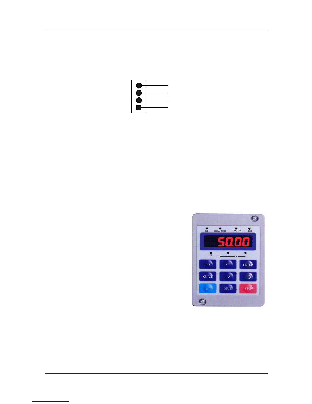
NICE3000 User Manual Structure of the control system and the component introduction
53
Function introduction:
LCD display, blue background white letters.
Floor address setting method:
Button pressing saving, oor saving button on the board.
GND
MP 2 4
1
3
4
2
MOD +
MOD -
Fig 3-21 power supply communication interface (CN2)definition
3.4 Sort of adjusting tools for NICE 3000
Adjusting tools of NICE3000 include four kinds: operation control and information display panel
(operation panel for short), small keyboard on MCB, upper monitor motoring software of NICE
3000, and PDA monitoring software. This chapter will give the instruction focusing on Operation
Panel and Smal
l Keyboard in common use.
3.4.1 Operation Panel Instruction
Through operation panel, user can modify the parameter, monitor the working state, and control
running (start and stop) when operation panel is working.
3.4.2 The Appearance and Function Section of Operation Panel
The appearance as Fig 3-22:
Instruction of function indicator lights:1)
RUN LED on indicates the controller is working.
LOCAL/REMOT Reserved.
FWD/REV Indicator of up and down. LED on indicates
the elevator goes down; LED off, up.
TUNE/TC Indicator of tuning. LED on, tuning.
Digital display area:2)
5-bit LED display, show t h e p a r a m e t e r s of m o v e
speed, bus voltage, etc.
Units indicator instruction:
3)
The units indicator indicates the unit of the figure of the digital display area. When two LEDs
are on, it indicates the unit bellow in the middle of them.
Hz: Frequency unit
A: Current unit
V: Voltage unit
RPM: Rotation speed unit
%: Percentage
Fig 3-22
Page 54
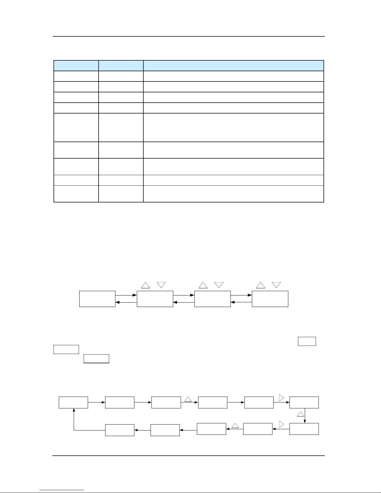
Structure of the control system and the component introduction NICE3000 User Manual
54
Instruction of buttons on the operation panel keyboard:4)
key name function
PRG Program key Enter or exit the primary menu and delete quick menu
ENTER Confirm Enter the menu level by level and confirm setting parameter
∧ Up Increase of date and function code
∨ Down Decrease of date and function code
>> Shift
It can select the displaying parameters circularly on the stop
displaying state and the running displaying state. It can also
select the modification bit of the pa
rameters when modifying the
parameters.
RUN Running
In the keypad operation mode, it is used for running and
operating the controller.
STOP/
RESET
Stop/reset
The key is for stopping the running when the controller is in the
running state, and for resetting the faulty status.
QUICK Quick key Enter or exit the quick menu
MF.K
Multi-function
selection
Display and remove of error message
3.4.3 Viewing and Operation Instruction of Function Code
3-level menu operational procedures:1)
NICE3000 adopt 3-level menu to conduct the parameter setting. It’s convenient to query and
modify function code and parameter.
3-level menu include: function parameter group (first level) →function code (second level)
→function code setting (third level). Operation procedures are as follows (Fig 3-23):
0.000 50.00F0-06F0
Dat e s how 1-level 2-level 3-level
PRG/
ENTER
PRGPRG
PRG ENTER ENTER
Change group
Modify code Change function code
Fig 3-23 level menu operational procedures
Instruction:When in 3rd menu, system can be backed to 2nd menu by pressing PRG or
ENTER . The difference between the two ways are as follows:it saves parameter after
pressing ENTER , then back to next function code in 2nd menu; And it does not save
parameter after pressing PRG , then keep staying at the current function code in 2nd menu.
Example: Change f
unction code F0-06 from 50.00Hz to 15.00Hz (bold means ash bit).
50.00F0-06F0-00
ENTER ENTER
50.00
10.0010.0015.00
F0-07
ENTER
F0
PRG
0.000 F0
PRG
PRG
Di spla y in st op
Fig 3-24 Example for Parameter Change
Page 55
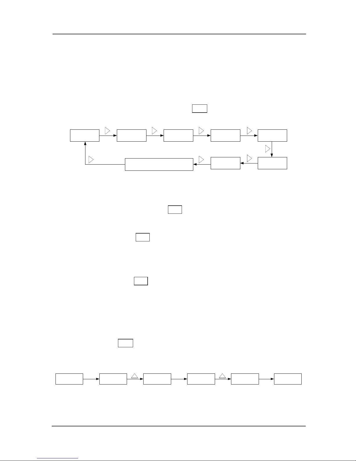
NICE3000 User Manual Structure of the control system and the component introduction
55
In the third level menu, if the parameter has no ash bit, it means the function code cannot be
changed and the possible reasons are:
This parameter of this function code cannot be changed, such as the actually detected 1)
parameter and running record parameter.
This function code cannot be changed in operating status and can only be changed when 2)
the controller is stopped.
To shift the status dis
play parameters by key �>> a)
Example:
Output
termi nal
High of inputLow of input
Current ly
place
load
Dec elerate dis tance of rated speed
Rat ed s peed Bus voltage
Fig 3-25 Example of Parameter Changing in Stopping State
In stopping and running status, the LED can display several status parameters, Whether to
display the status parameters is dependent on the bit setting of FA-01 (running parameter) and
FA-02 (stopping parameter). Through key�>> , user can shift the display in sequence and
display the stopping or running status parameters circularly.
In stoppi
ng state, there are 12 status parameters for NICE3000, user can shift to display the
parameters circularly by key �>>�. The parameters are: rated speed, bus voltage, low bit
of input terminal, high bit of input terminal, output terminal, currently oor, currently place, car
load, decelerate distance of rated speed, car top input state, car top output state and system
state. Users can select the de
sired parameters through the bit of FA-02.
In running state, there are 16 state parameters for NICE3000. Users can shift to display the
parameters circularly by key �>>�. The parameters are: running speed, rated speed, bus
voltage, output voltage, output current, output frequency, low bit of input terminal, high bit of
input terminal, output terminal, currently oor, currently place, car load, inpu
t of CTB-A, output
of CTB-A, system state, and advance torque current. Users can select the desired parameters
through the bit of FA-01.
Error information reading 3)
When error occurs in the controller, the error information will be displayed on the panel. It is
convenient to find reasons for the error and get rid of the error as soon as possible.
The controller can save the last 11 error codes. User
s can read the first error code in the
following way:
FC-06FC-00FC
0000
0.000 F0
PRG ENTER ENTER
Date Di splay
Fig 3-26 way of error information reading
Page 56
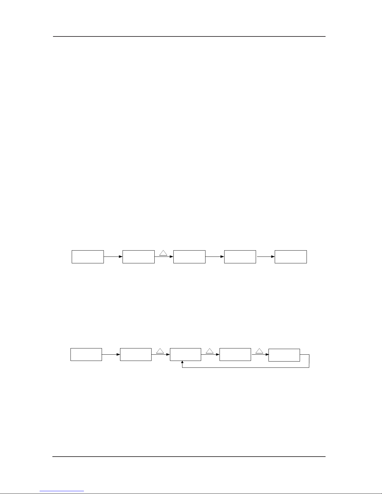
Structure of the control system and the component introduction NICE3000 User Manual
56
3.4.5 Operation Instruction of Quick Menu
Quick menu of NICE3000 is created for the purpose of making it convenient for users to check
and modify the frequently used parameters. The parameter display mode in quick menu is
“uF3.02”, which means changing the parameter in quick menu is the same with that in
common programming status.
Up to 16 parameters can be saved in quick menu. If 16 parameters are
stored and more are
wanted, the “FULL” will be displayed; if entering the menu and the “NULL” is displayed,
which means no parameter is stored in the quick menu.
There are 16 parameters stored in advance in NICE 3000:
F0-03
:
Maximum running speed F5-36
:
Input way of weighing
F0-04
:
Rated speed F6-00
:
Top oor
F0-05
:
Rated load F6-02
:
Parking oor
F1-12
:
Encoder pulse number per rotation F8-01
:
Advance torque selection
F3-00
:
Start-up speed F8-02
:
Advance torque offset
F3-01
:
Time keeping F8-03
:
Drive gain
F3-10
:
Re-leveling speed F8-04
:
Brake gain
F4-00
:
Leveling adjusting FC-22
:
Latest error type
Users can modify it according to needs.1)
Add parameters in the quick menu:
F0-05F0-05
F0-05
0.000 F0
PRG QUICK ENTER
Date Display Flash display Stop flashing
Fig 3-27 Add parameters in the quick menu
In the 2nd level menu, press QUICK to enter the quick menu. The ashing indicates whether
to save the parameter into the quick menu. When it stops ashing, the operation is completed;
Press PRG to cancel, then it stops ashing, and the operation is cancelled.
Parameters out and modifying in the quick menu2)
Select out and modify parameters F0-03, F3-10, F5-3
6, F8-11 from the quick menu.
uF5.36uF3.10
uF8.11
0.000 uF0.03
QUICK
Date Displa y
Fig 3-28 Change the parameter in the quick menu
In stopping or running display interface, press QUICK to enter quick menu, and press UP/
DOWN to select different parameters, and then press ENTER to enter the next level menu. The
changing method is the same with that in the third level menu. Press QUICK to back to last
screen and the changed parameter will not be saved.
Delete the parameter in the qui
ck menu:3)
If there are parameters as F0-03, F3-10, F5-36, and F8-11 in the quick menu, and you want to
Page 57
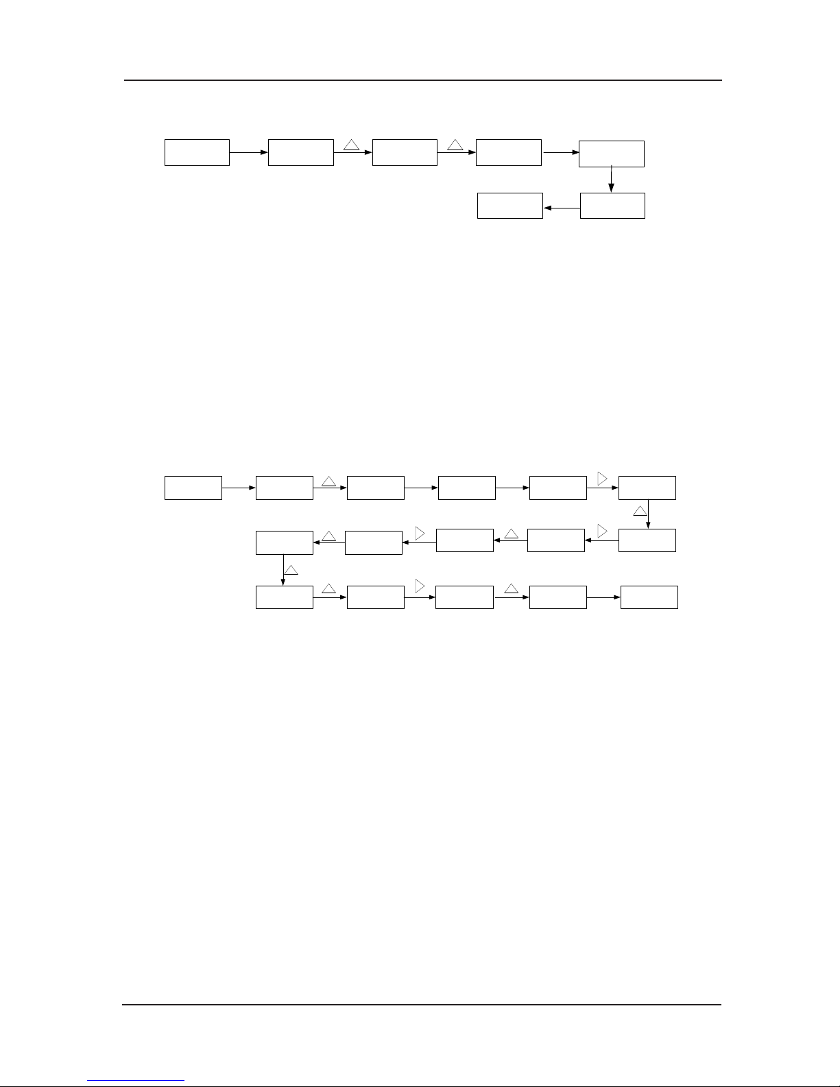
NICE3000 User Manual Structure of the control system and the component introduction
57
delete F5-36, please operate as follows:
uF5.36uF3.10
uF5.36
0.000 uF0.03
QUICK
Flash display
PRG
ENTER
0.000 uF8.11
QUICK
Date display
Fig 3-29 Delete the parameter in the quick menu
Press PRG in the quick menu, the displayed parameter ashes, and prompt the user whether
to delete the parameter in the menu. Pressing ENTER will delete the parameter in the menu
and the displayed parameter stops flashing, while pressing QUICK will cancel the deleting
operation and the displayed parameter stops ashing, and the operation is completed.
If the
last parameter is deleted, and “NULL” will be displayed, that means no parameter is stored
in the menu.
3.4.6 Password Setting
In order to protect the parameter more effectively, the controller provides the password
protection.
The figures below show how to change the password to 12345 (bold shows ashing bit):
000000
FP-00FP
ENTER
000000
10000
1000012000
1200012300
0.000 F0
PRG ENTER
12300 12340 FP FP-00
Date d ispaly
ENTER
12345
Fig 3-30 Password setting procedure
When the user has set the password (the password parameter of FP-00 shouldn’t be ZERO),
the password protection function is valid once the user presses PRG, and the controller
shall display“------”. The user can only enter the menu after inputting the user password.
Otherwise, the user cannot enter. For factory setting parameters editing, the user still need
to i
nput the factory password. (Warning: do not change the factory setting parameter; if the
parameter values are wrong, the controller will work abnormally, even be damaged.)
When the password protection is unlocked, user can change the password freely, and the last
input number will be the user password.
If the user wants to cancel the password protection function, enter after inputting the password
a
nd set FP-00 as 0; when the power is on, the parameter will be protected by the password if
FP-00 isn’t set ZERO.
3.4.7 Function and Use Instruction of Small Keyboard
Small keyboard is consisted of three numeral lamp and three keys, and it takes charge of
displaying the information of main board MCB and receiving the simple order inputted. The
menu is divided into function F0~F8.
Page 58
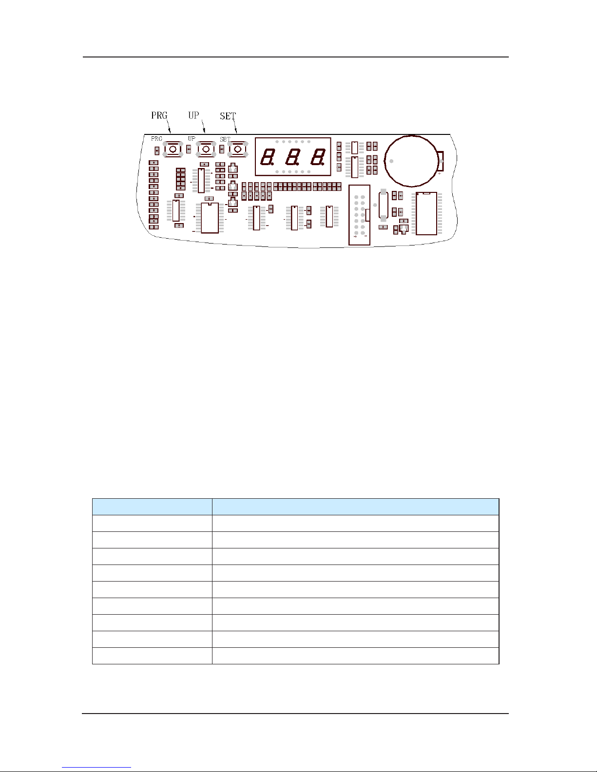
Structure of the control system and the component introduction NICE3000 User Manual
58
3.4.8 Appearance of Small Keyboard
Appearance is as follows:
Fig 3-31
3.4.9 Function Instruction of Small Keyboard
3 keys are defined as PRG、UP、SET, and marked beside.
PRG: In any state, press PRG, the function code will be displayed and it can be changed 1)
by pressing UP;
UP: In function group menu, pressing UP can change function code circularly, as 0, 1, 2, 3, 2)
4, 5, 6, 7, 0…. There are 8 function codes defined in MCB controller at present. Additional,
in s
pecial function group, UP also could be used for inputting the order;
SET: In function group, press SET and it will enter this menu. In special function group, 3)
after inputting simple order and pressing SET, it will save and enter F0 automatically.
In the adjusting state, press PRG first, then select the function group code with UP. It displays
as 0,1,2,3,4,5,6,7,0,1,2…then press SET to enter the s
tate. If you press three buttons at the
same time or either two of them, the operation is not valid.
3.4.10 Function Code of Small Keyboard
Code Date menu content
F 0 Floor and run direction information
F 1 Input of oor running order
F2 Error reset
F 3 Time display
F 4 Contract number
F 5 Run times display
F 6 reserved(forbid user setting, dangerous!)
F 7 Floor auto-tuning order input
F8 Testing function
Page 59

NICE3000 User Manual Structure of the control system and the component introduction
59
3.4.11 Function Instruction of Each Menu
F0 (Floor and run direction information): F0 date menu will be display as default after electrify.
The first bit of numeral lamp is used for direction; the second and the third bit are used for
displaying current floor. When stopping, first lamp doesn’t display, and when travel up or
down, the first display direction up or down. If error (no error formerly),
the numeral lamp
automatically switches to display the error code. If error automatically disappears, F0 date
menu will be display.
F1 (Input of floor running order): After entering F1 date menu through PRG, UP, SET, the
numeral lamp display the lowest oor (the same as F6-01), and you can select oor (lowest to
top) by UP, then press SET to save the data. The lift will travel to the aimed oor. T
he numeral
lamp will switch to display F0 date menu after arriving the destination.
F2 (Error reset): After entering F2 date menu through PRG, UP, SET, the numeral lamp display
“0”. The parameter can be changed through UP, with the range from 0~1. And ‘1’
denotes order of error reset, then press SET to save. The numeral lamp will switch to display
F0 date menu.
F3 (Time display): After entering F3 d
ate menu through PRG, UP, SET, the numeral lamps
display time circularly. For example: 2005-03-01-08-30.
F4 (Contract number): After entering F3 date menu through PRG, UP, SET, the numeral lamps
display the user’s contract number.
F5 (Run times display): After entering F3 date menu through PRG, UP, SET, the numeral lamps
display run times circularly. For example: “100000”, display 999999 times at mo
st..
F6: Reserved. (forbid user setting, dangerous!)
F7 (Floor auto-tuning order input): After entering F7 date menu through PRG, UP, SET, the
numeral lamp display ‘0’. The parameter can be changed through UP, with the range from 0
~1. And ‘1’ denotes order of auto-tuning of oor, and then press SET to save. The controller
begins auto-tuning. At the same time, the numeral lamp switches to display F0
date menu. After
auto-tuning of oor, F7 backs to 0 automatically.
F8 (Testing function): After entering F7 date menu through PRG, UP, SET, the numeral lamp
display ‘00’. The range of F8 is from 00~04. Instructions as follows:
00-none;
01-forbid calling outside;
02-forbid opening door
03-allow overload
04-short limit switches
Press SET to affirm after changing the parameter and the numeral ashing ‘E88’ t
o show
that the lift is in testing state. Press PRG to quit and F8 backs to ‘0’ automatically.
In addition, when small keyboard on main control panel enters F8 group and in test function
mode, SET equals to close door button.
Page 60
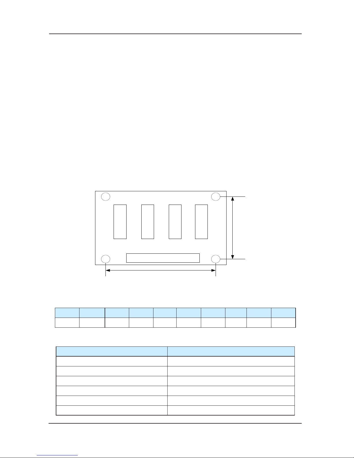
Structure of the control system and the component introduction NICE3000 User Manual
60
3.5 Advanced door-open module(SCB)
General introduction 1)
MCTC-SCB-A is one of the matching accessories of NICE 3000 elevator integrated controller
system. In accordance with the various customer needs and expansion of our product range,
we developed the Advance door-open module MCTC-SCB-A.
The MCTC-SCB-A can relize the re-levelling after opening and the advanced door-opening
functions when it app
lied to the NICE series controllers.
For the inconvenience that caused by the steel wire rope or other factors when realize the releveling function, the SCB-A will ensure the elevator to run to the leveling position with the releveling speed on the door-open state.
The advanced door-open function: When the lift is running automatically, the speed is slower
than 0.3m/s in the stopping course, and
the door zone signal is valid, SCB-A short the door
lock signal through advanced door-open contactor, and pre-opens the door to make the most
efficiency.
Appearance and measurement2)
K1
95mm
56mm
K2 K3 K4
Fig 3-32 appearance diagram
Terminal 3)
1 2 3 4 5 6 7 8 9 10
24V COM FL1 FL2 SY SX1 SX2 SO1 SO2
Terminal specification from left to right side
Specifications
FL1 re-leveling door-area signal 1
FL2 re-leveling door-area signal 2
SY Advanced door-opening contactor output
SX1 door-area input
SX2 advanced door-open output feedback input
SO1、SO2 Door-lock circuit
Page 61
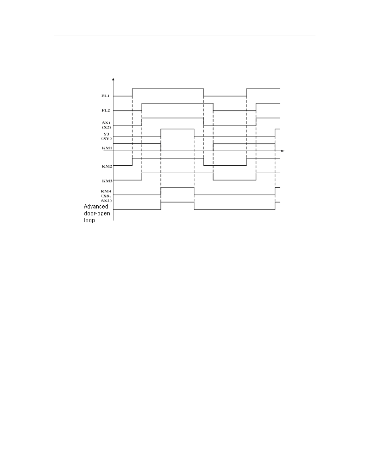
NICE3000 User Manual Structure of the control system and the component introduction
61
Logic sequence 4)
The time sequence diagram of the advanced door-open module shows the relations between
relays and signals, the high electric level indicates the signal is valid.
Fig 3-33 Time sequence diagram
When apply power, according to the wiring diagram, the relay KM1 will operate, and the
relevant contact will activate; when elevator run and detect out the up re-leveling signal 1(FL1)
is valid, the relay KM2 will operate and the relevant contact shall activate; when detect out the
down re-leveling signal 2(FL2)is valid, the relay KM3 will operate and the relevant co
ntact
activate, accordingly will make the door zone signal input SX1(X2) valid; when the system
detect out this signal, the advanced door-open output relay Y3 (SY) will output, the KM4 will be
valid together with the KM2 and KM3, and the relevant contacts will be activated, the system
will detect out that the advanced door-open signal SX2(X8) valid, at the same time the lock
will operate to short
the door-lock and to realize the advanced door-open function. After the
advanced opening, the advanced opening relay will be break, the KM4 will stop operating, the
advanced opening signal input signal will be invalid and the lock break; when the up re-leveling
signal 1(FL1) is invalid, the KM2 will stop operation and the door area input signal is invalid;
when the down re-leveling signal 2 (FL2)
is invalid, the relay KM3 stop operation, then the KM1
will operate and the relevant contacts will activate.
Re-leveling door area sensor and installation method.5)
The advanced door-open/ re-leveling function need to add leveling sensor, up leveling sensor,
up re-leveling door area sensor FL1, down re-leveling door area sensor FL2, and down leveling
sensor. Please install it by sequence or the d
irections will be reversal.
In the condition of on-site application, if there is only one door area sensor signal, user needs
to short the FL1 and FL2, and the up/down re-leveling signals are taken for the same one.
Page 62
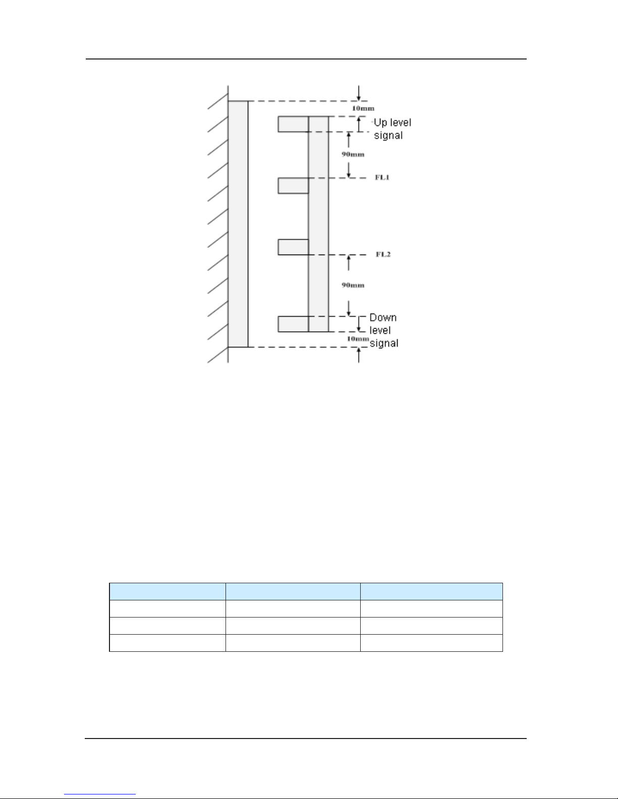
Structure of the control system and the component introduction NICE3000 User Manual
62
Fig 3-34 Up/Down re-leveling door area sensor installation
Parameter setting specification 6)
Different on-site applications:
4 on-site sensor signals, namely the up leveling signal, up re-leveling door area signal a)
input (FL1), down re-leveling door area signal input (FL2), down leveling.
Disposal method: the X1,X2 that the leveling signals connect to the NICEC 3000 control
system, the up re-level
ing door area signal input to FL1, the down re-leveling door area signals
input to FL2, and they are all N.O settings, if the on-site sensor is N.C. setting, please use the
middle relay to switch to N.O inputting. When the elevator up run, detect the up leveling signal,
FL1 and FL2 signals, and processed by the NICE 3000 system to realize the advanced dooropening; same for the down running.
Relat
ive function codes setting:
NICE3000 I/O Parameter setting
F5-02 X2 03
F5-08 X8 22
F5-30 Y3 03
In the application with NICE 3000 system, accordingly as the user’s manual, set the F5-02 as
03 door area N.O. inputting, F5-08 as 22 advanced door-open output feedback N.O. inputting,
F5-30 as 3 advanced door-open contactor outputting.
3 on-site sensor signals, namely the up leveling signal, door area signal, down leveling b)
Page 63
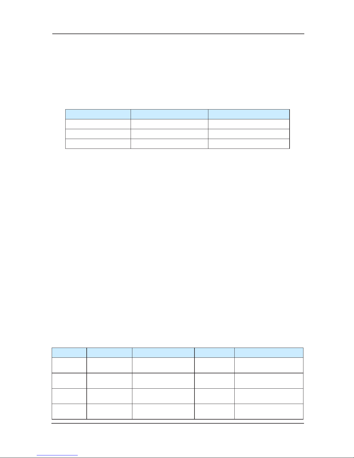
NICE3000 User Manual Structure of the control system and the component introduction
63
signal.
Disposal method: the X1 and X3 that the leveling signal connect to the NICE 3000 control
system, break the door area signal and the X2, and connect the door area signal to the FL1
and FL2, that means connect both FL1 and FL2 to door area signal. If the door area signal is
N.C inputting, please use the relay to switch to N.O. inputting. When the elevator is up running,
detect out the up leve
ling signal and the FL1 and FL2 are all valid, the advanced door-open
function is operated. The down run is the same. Function codes setting:
NICE3000 I/O Parameter setting
F5-02 X2 03
F5-08 X8 22
F5-30 Y3 03
In the application with NICE 3000 system, accordingly as the user’s manual, set the F5-02 as
03 door area N.O. inputting, F5-08 as 22 advanced door-open output feedback N.O. inputting,
and F5-30 as 3 advanced door-open contactor outputting
Remark:
On the actual application, users can choose any I/O function codes by parameter setting
On the sc
heme 2, short the FL1 and FL2 to test (need the professional monitor). Considering
from safety, the 2 re-leveling door area signals are recommended to ensure the smooth running
of the system.
3.6 Voice landing report (CHM)
Wiring 1)
4PIN terminals are 24V、MOD+、MOD-、COM.
24 v pin connect to DC 24v power +, COM connect to DC 24v power -.
MOD+、MOD- are the positive/negative of the 485 communication in
terface differential signal.
The voice reporter will be ready for work after the correct wiring as above introduction.
Parameter setting2)
The three buttons are FUN、+ 、-.
Settable parameter table:
Serial No. Function Reference Default Specification
1
Language
select
Chinese, English,
Chinese/English
Chinese
2
Background
music select
1~10 1
3 Music volume 1~16 12
1:mute 16:Max.
volume
4
Voice report
volume
1~16 12
1:mute 16:Max.
volume
Page 64
Structure of the control system and the component introduction NICE3000 User Manual
64
Parameter configure process: (default to enter the run mode after the power applied and ringing
for 3 times, user can operate setting)
First, press FUN key, the reporter will prompt function 1—“reporter language select”
Then set the parameters by pressing “+” or“-“, and the reporter will report the select
parameter – Chinese, English, or Chinese/English
At last, by pressing “FUN” key, the announciato
r will save the parameter and prompt the
next function –“background music selected”
Successively, every time user pressing the “FUN” key, the system will save current
parameter and prompt the next function. When the last parameter has been set, press “FUN”,
the reporter will prompt” save the setting, enter the running mode”, the reporter will back to
running mode.
When in the Run mode, only by pre
ssing “FUN” key can set the parameter again, during
setting the system will give no response to the reporting command, and the system will
automatically save the parameters and back to run mode after 10s non-operation when there is
no voice reporting, at the same time prompt “save the setting, enter the running mode”.
When set the “background music select” parameter, after pressing the “+” or “-“,
apart from the reporting of parameter value “ 1~10”, the system will also play the relevant
background music. Before the music has finished, the system will not start the 10s overtime
operation, but can be respond to any pressing to end the music and set the parameter.
When set the “background music volume” and “station reporting volume” parameters,
after pressing the “+” or “-“, apart from the re
porting of parameter value “1~10”, the
system will also play the relevant background music or the reporting voice. Before the music
has finished, the system will not start the 10s overtime operation, but can be respond to any
pressing
Advanced setting
For the Operations that changing the reporting content, greetings, advertising message or
some special configuration to different oors, the SD card in
the reporter need to be take out
to change relevant document. The illustration text is listed in the SD card – “advanced setting
operation description”.
3.7 Weighing sensor (LDB)
Technical parameters of weighing sensor
System working voltage DC24V±15%
Best effective distance 15~30mm (Specification refers to chart 9-10)
Minimum distance with full load 15mm Specification refers to chart9-10)
Best effective distance with no load 25mm (Specification refers to chart 9-10)
connection wiring
of sensor
Red line +24V
Black line 0V
brown line 0~10V Signal wiring
Page 65
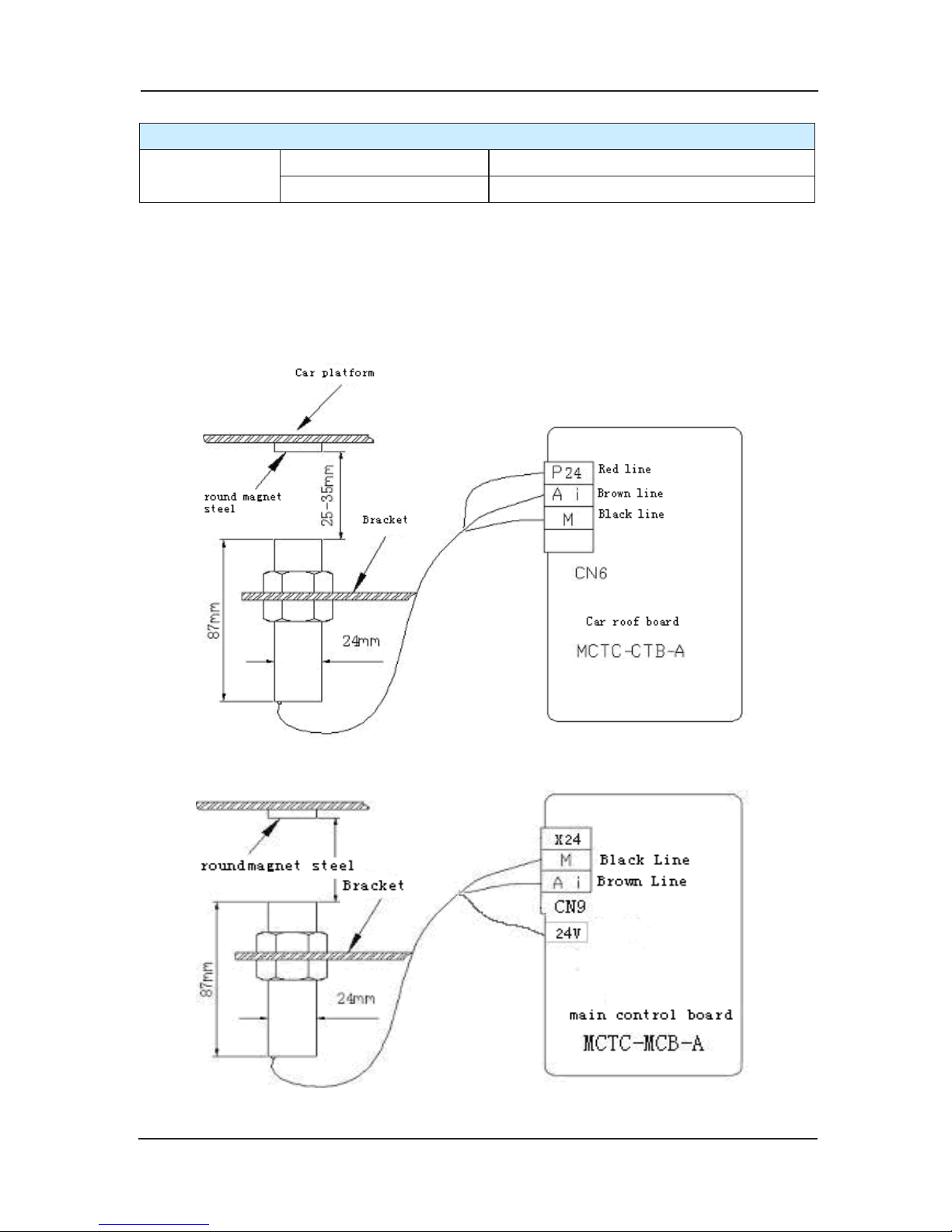
NICE3000 User Manual Structure of the control system and the component introduction
65
Technical parameters of weighing sensor
size
Diameter 24mm
Height 87mm
Users can choose to equip weighing board (MCTC-LDB-A) for providing the system with the
signals of light load, full -load and over-load and complete to compensate analog weight, in
order to improve stability of lift running.
Installation Mode:
It’s recommended to be installed into the bottom of the car.
Fig 3-35
Installation sketch of weighing transducer (Transducer connected to the car top board)
Fig 3-36
Installation sketch of weighing transducer (Transducer connected to the main control board)
Page 66
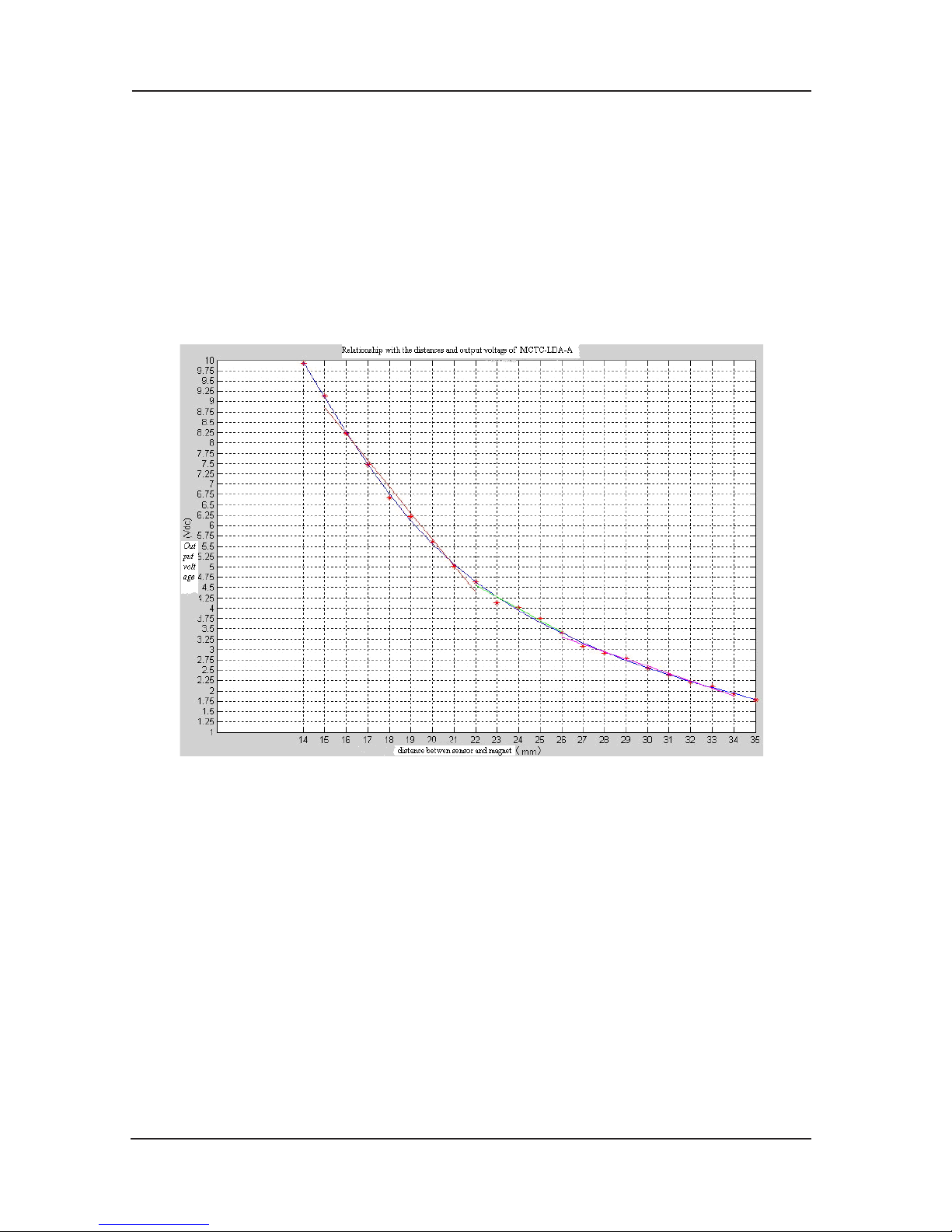
Structure of the control system and the component introduction NICE3000 User Manual
66
Attention items:
The installation position should be close to the middle of the car cage as possible as it can.
The square porcelain steel with pasted paper is the working surface, and it should be opposite
to the transducer.
If there’s no voltage outputting after installation, please try to change the polarity of the square
porcelain steel.
3.7.1 The relationship chart between the distance (mm) from
top of the weighing transducer to
the square porcelain steel and transducer’s outputting voltage (V):
Fig 3-37 Weighing sensor’s outputting voltage
User can choose the best install distance according to the car cage’s compression
deformation from no load to full load and choose the maximum distance from it.
For example: If one customer’s compression deformation is 5mm, the user can analyze
according to chart9-7-3: ①、If the distance of no load is 21mm, and the sensor’s outputting
voltage is 5.25V, wh
en the distance of full load is 16mm, sensor’s outputting voltage will be
8.25V, and the change of the voltage from no load to full load is 3V. ②、If the distance of no
load is 35mm, and the sensor’s outputting voltage is 1.75V, when the distance of full load is
30mm, sensor’s outputting voltage will be 2.5V, and the change of the voltage from no load to
full load is 0.75V. Through the analysis of
① and ② we can conclude that the resolution ration
of ① is 4 times than that of ②. Obviously the higher resolution ration is, the better it will be.
Page 67
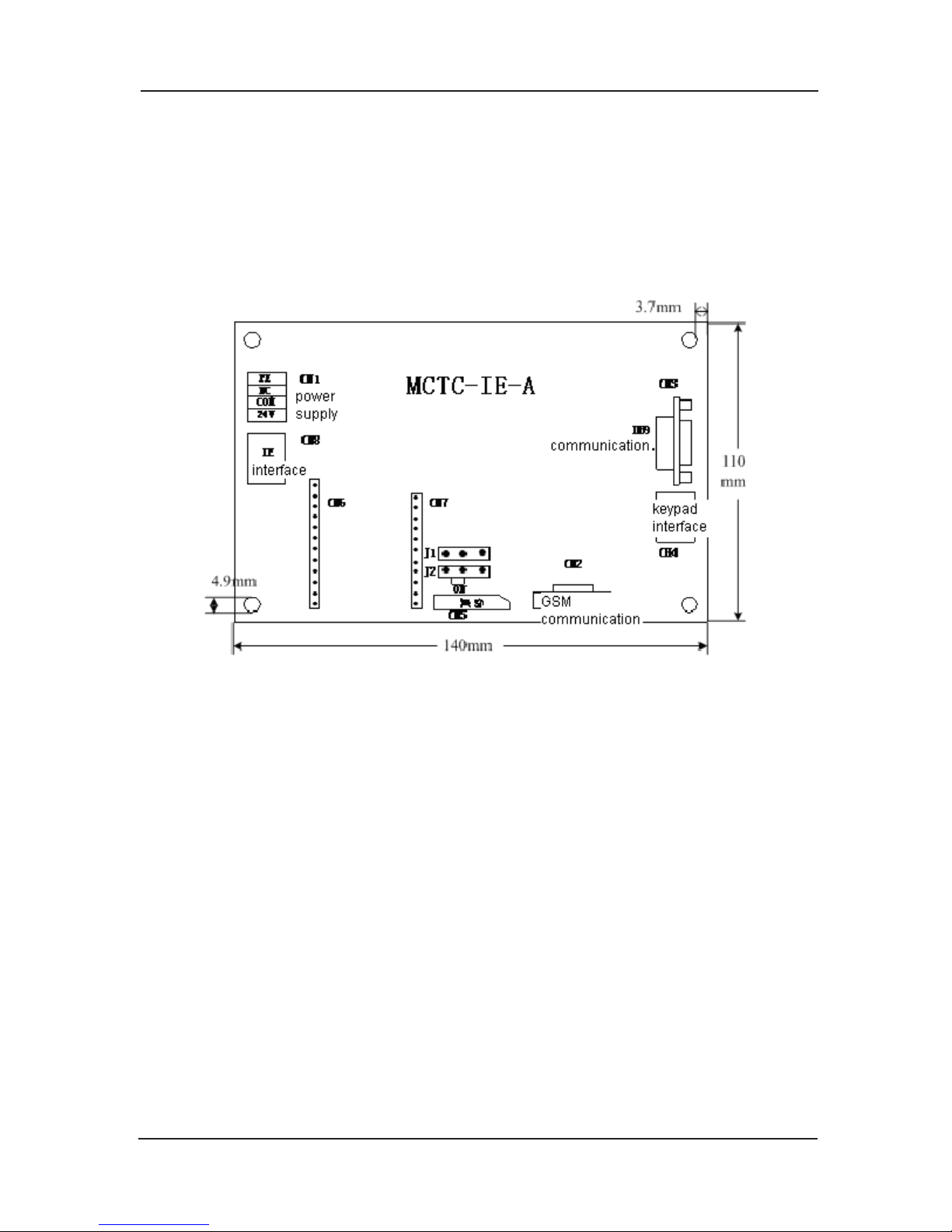
NICE3000 User Manual Structure of the control system and the component introduction
67
3.8 IE module Applied to the elevator faults conditions the MCTC-IE-A
MCTC-IE-A –GSM message module is applied to the elevator faults condition, the MCTC-IE-A
board collects the error information and sends a prompt message to the fixed cell-phone to
remind the elevator maintaining technician about the error condition, and ensure the prompt
maintaining of the elevator.
Measurement diagram
1)
Fig 3-38 Mounting measurement of MCTC-IE-A
Remark: GSM module is needed when mounting the MCTC-IE-A,so the total height is 35mm.
Using method 2)
The function of MCTC-IE-A-GSM is when the elevator error occurred or switch from one error
to another one, the MCTC-IE-A inquire error information to main board by communication, then
send the error information message to the cell-phone after the IE board
collected the error
information.
Cell-phone number settinga)
The message that user’s cell-phone received can not be automatically saved, and user
can save the fault message manually if necessary. The cell-phone number can be set by the
keypad inputting, and the number data will be stored on the 24LCO8 chip.
Storing method:
F0-00:cell-phone number 1~4 bit;
F0-01:cell-phone number 5~8 bit;
F0-02:cell-p
hone number 9~11 bit,last bit display“E”,need no setting;
For instance: if a phone number is 13912614479,the parameter settings are as following:
Page 68

Structure of the control system and the component introduction NICE3000 User Manual
68
F0-00:1391
F0-01:2614
F0-02:479E,“E” is factory default,need no setting;
wiring b)
3 terminals are needed for GSM module:
CN1
Power supply terminal, 1 set 24v power supply, PE and NC need no wiring;
CH4
The interface of adjusting keypad sets the number by the adjusting keypad.
CN3
MCTC-MCB-A communication terminal, connect this terminal and the CN2 on the control board
by a communication wire, and
the wire is factory configured. 2 pins on the right side of J9
should be short;
Other terminals need no wiring;
jumper selection
There are 2 jumpers on the MCTC-IE-A-GSM board, and the 2 should all short to the left side
when using. Please refer to the measurement chart – short the 2 jumpers to “ON” side.
other configure
User need to add a general SIM card on the module•
Terminal CN2 of MCTC-IE-
A is communicated with the J1 of GSM, its factory default. •
3.9 Other optional components
3.9.1 Operation panel and communication cable(OPR、OPL)
Operation panel (OPR): MCTC-OPR-A.
Communication cable (OPL): MCTC-OPL0150, 0150 standing for 15m length.
Connection cable: MCTC-CCL0150, 0150 standing for 15m length.
If users need panel matched cable, they can choose the scope of cable with length 2m, 5m,
1
5m, 30m, 50m, and 100m.
3.9.2 Others
To coordinate with the use of NICE 3000 system, Suzhou Monarch Control Technology Corp.,
Ltd. provides other accessories such as group control board (MCTC-GCB-A), short message
control board (MCTC-IE-A), PDA adjusting machine (MCTC-PDA-A), Serial transferring to
parallel control board (MCTC-HPB-A), residential community monitoring interface board
(MCTC-BMS-A) and
etc. If you need any of them, please contact with the supplie
Page 69

4
Installation and wiring
Page 70
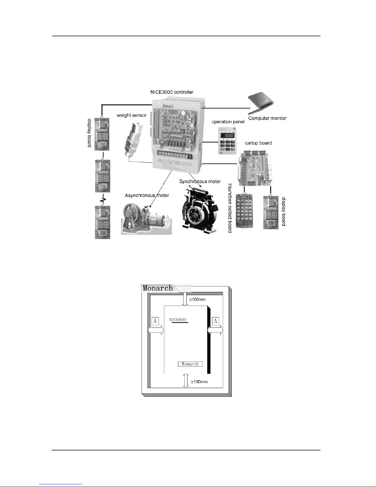
Installation and wiring NICE3000 User Manual
70
Chapter 4 Installation and wiring
4.1 System Configure Introduction
Fig 4-1 System Configure Diagram
4.2 Mechanical Installation
NICE 3000 controller installation size requirements:
Fig 4-2 controller installation size requirements
The unit in the chart is mm.
A shall be bigger than 50mm for the controller of 22kW or above.
Page 71
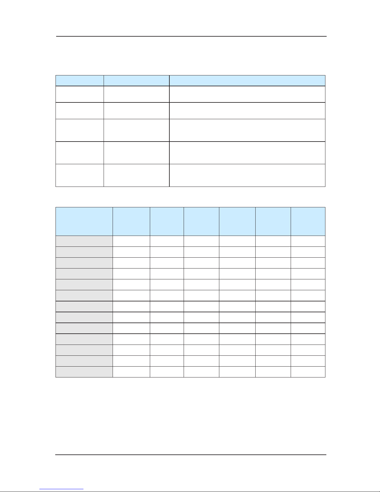
NICE3000 User Manual Installation and wiring
71
4.3 Electric Installation and Wiring
4.3.1 using of External Device
Device Position Function
Air switch
Front-end of input
circuit
Cut off the power and provide short protection.
safe contactor
between air switch
and controller
Switch on/off the controller; controlled by safe circuit.
AC input
reactor
Controller input side
improving input power factor; eliminate high frequency
humorous wave in input side; eliminate current
unbalance due to input phase unbalance;
DC reactor sta
ndard internal
improving input power factor; eliminate high frequency
humorous wave in input side; eliminate current
unbalance due to input phase unbalance;
AC output
reactor
Between controller
and motor, and near
controller
If the distance between the vector driver and the motor
is longer than 100m, it is recommended to install the
AC output reactor.
Selecting of External Device
Type
Vacancy
(MCCB)
(A)
Contactor
(A)
Input
side main
circuit lead
(mm²)
Output
side main
circuit lead
(mm²)
Control
circuit lead
(mm²)
Grounding
(mm²)
NICE-L-A/B-2002 20 16 4 4 1 4
NICE-L-A/B-2003 32 25 6 4 1 4
NICE-L-A/B-4002 16 10 4 4 1 4
NICE-L-A/B-4003 25 16 4 4 1 4
NICE-L-A/B-4005 32 25 4 4 1 4
NICE-L-A/B-4007 40 32 6 6 1 4
NICE-L-A/B-4011 63 40 6 6 1 4
NICE-L-A/B-4015 63 40 6 6 1 4
NICE-L-A/B-4018 100 63 10 10 1 4
NICE-L-A/B-4022 100 63 10 10 1 4
NICE-L-A/B-4030 125 100 16 16
1 4
NICE-L-A/B-4037 160 100 16 16 1 4
NICE-L-A/B-4045 200 125 25 25 1 4
DBR
The following types of NICE 3000 integrated controller have been equipped with brake unit
inside with power no more than 30KW. User just needs to externally connect brake resistance.
For those types above 30KW, it needs brake unit and brake resistance.
Page 72
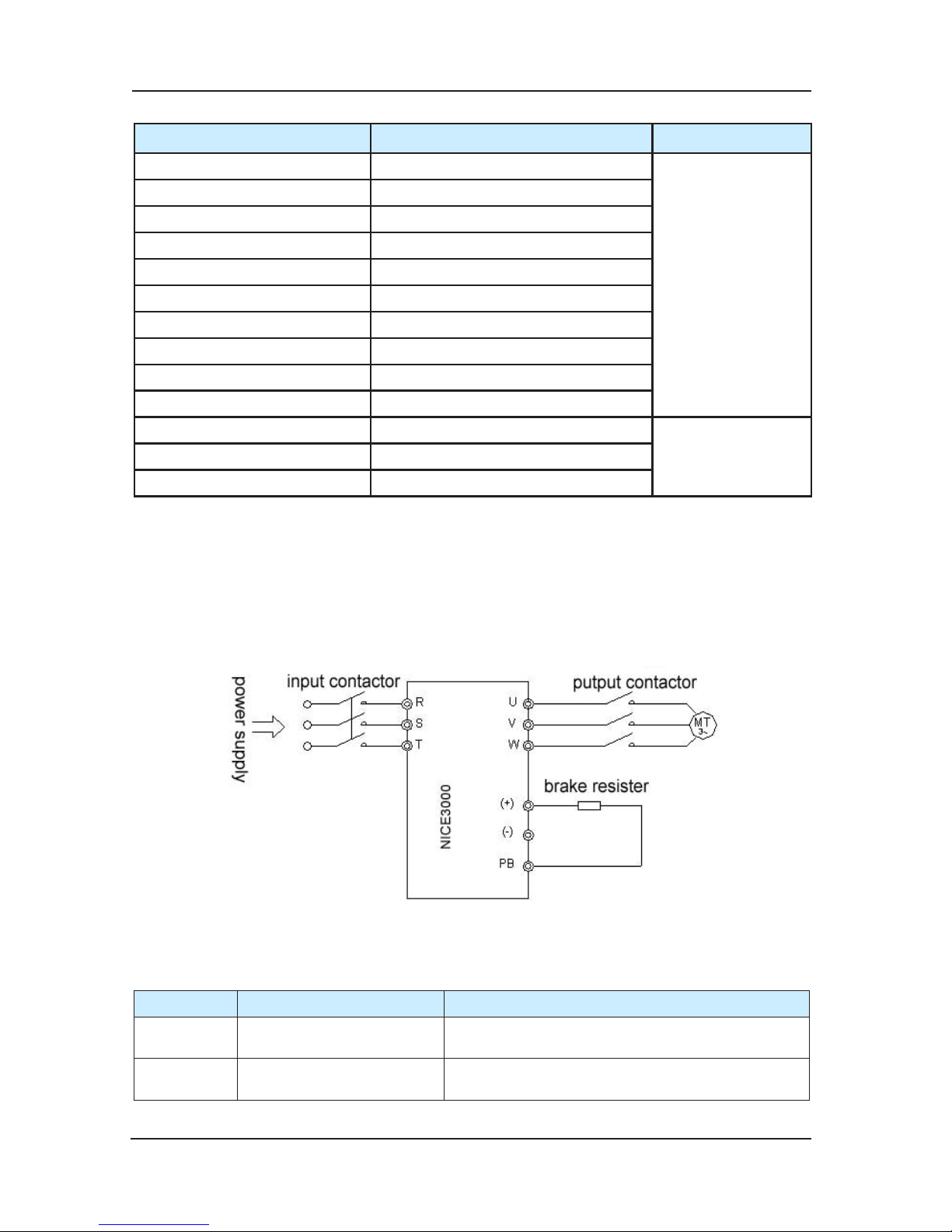
Installation and wiring NICE3000 User Manual
72
Type Configure of brake resistance Brake unit
MCTC- DBR-4001 300W ,200Ω
Standard equipment
MCTC- DBR-4002 600W ,220Ω
MCTC- DBR-4003 1100W ,130Ω
MCTC- DBR-4005 1600W ,90Ω
MCTC- DBR-4007 2500W ,65Ω
MCTC- DBR-4011 3500W ,43Ω
MCTC- DBR-4015 4500W ,32Ω
MCTC- DBR-4018 5500W ,25Ω
MCTC- DBR-4022 6500W ,22Ω
MCTC- DBR-4030 9000W ,16Ω
MCTC- DBR-4037 11000W ,13Ω
External equipmentMCTC- DBR-4045 13500W ,10Ω
MCTC- DBR-4055 16500W ,9Ω
4.3.2 Electric wiring
Electric wiring include three parts:Controller main circuit, main control board wiring and
encoder wiring.
Main circuit connection and terminal function1)
main circuit:a)
Fig 4-3 Main Circuit Wiring
terminal function:b)
Terminal Name Instruction
R、S、T
3-phase power input
terminal
Connect 3-phase AC380V
(+)、(-)
Positive and negative
terminals of DC bus
Shared DC bus input, for controller above 37kW,
they are for brake unit
Page 73
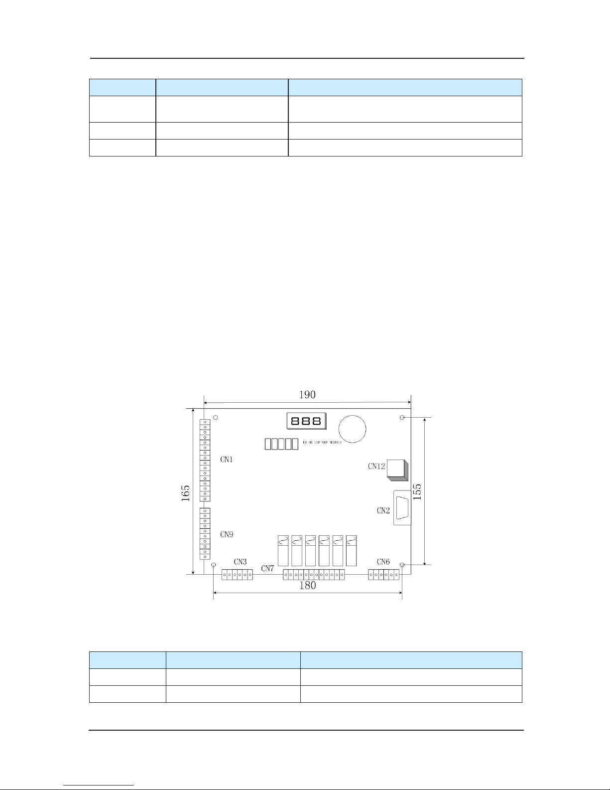
NICE3000 User Manual Installation and wiring
73
Terminal Name Instruction
P(+)、PB Terminals for brake resistor
For controller below 30kW(include 30kW) they are
for brake unit
U、V、W controller output terminal Connect 3-phase motor
PE Terminal for grounding Grounding terminal
Note:
Select the recommended resistor according to selection form of brake resistance’s type.
Controller output circuit grounding or short circuit is absolutely not permitted.
Contro
ller output cables of U, V and W should be in metal pipe with grounding, and
divided or vertical with control circuit cables.
If the cables between the motor and the controller are too long, electrical resonance
may occur due to the distributed capacitance, which may result in damaging the motor
insulation or big leakage current that will make the controller go into protective status.
Grounding
terminal must be connected to earth reliably, the grounding cable should be
thick and short, the recommended grounding cable should be special yellow-green cable
above 4 mm2 with several copper cores. And the grounding resistance shall be less than
4Ω. Do not share the PE and neutral line of the main supply.
MCTC-MCB-A main control board wiring instruction2)
MCTC-MCB-A main control board installa
tion location:a)
Chart 4-4 MCTC-MCB-A Main Control board Dimension
indicator light instruction of MCB:b)
Terminal Name Instruction
ER Error indicator when error, ER indicator lighten (red)
OK OK indicator when no error, OK indicator lighten (green)
Page 74
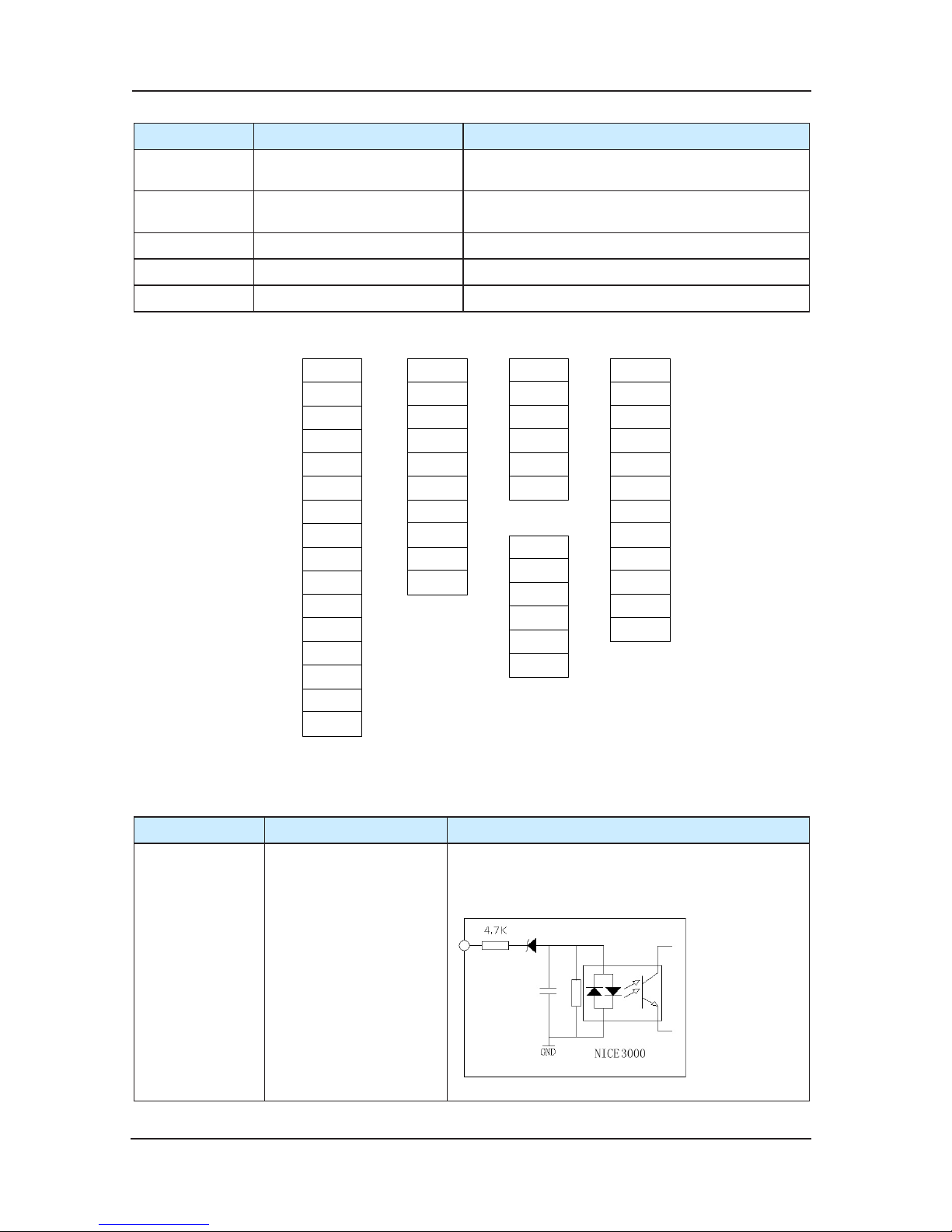
Installation and wiring NICE3000 User Manual
74
Terminal Name Instruction
COP
CTB communication
indicator
when communication well between MCB and
CTB, COP indicator lighten (green)
HOP Hall call indicator
when communication well between MCB and
HCB, HOP indicator lighten (green)
MODBUS Parallel indicator The parallel communication is normal (green)
X1~X24 Input signal indicator when external input, indicator lighten (green)
Y1~Y6 Output signal indicator when si
gnal output, indicator lighten (green)
terminal list:c)
X1
X2
X3
X4
X5
X6
X7
X8
X9
X10
X11
X12
X13
X14
X15
X16
C
N
1
X17
X18
X19
X20
X21
X22
X23
X24
M
AI
C
N
9
24V
COM
MOD
+
MOD-
CAN+
CAN-
C
N
3
15V
PGM
PGA
PGB
PGM
PE
C
N
6
Y1
M1
Y2
M2
Y3
M3
Y4
M4
Y5
M5
Y6
M6
C
N
7
Chart 4-5 MCTC-MCB-A Terminal Definition
Plug CN1and CN9 instruction:d)
Terminal Name Instruction
X1~X24
digital signal input
function selection
1.photocoupler isolation input
2.input resistance : 4.7K
Ω
3.input voltage range:10~30V
4.input current limit :5mA
terminal function decided by F5-01~F5-24
Page 75
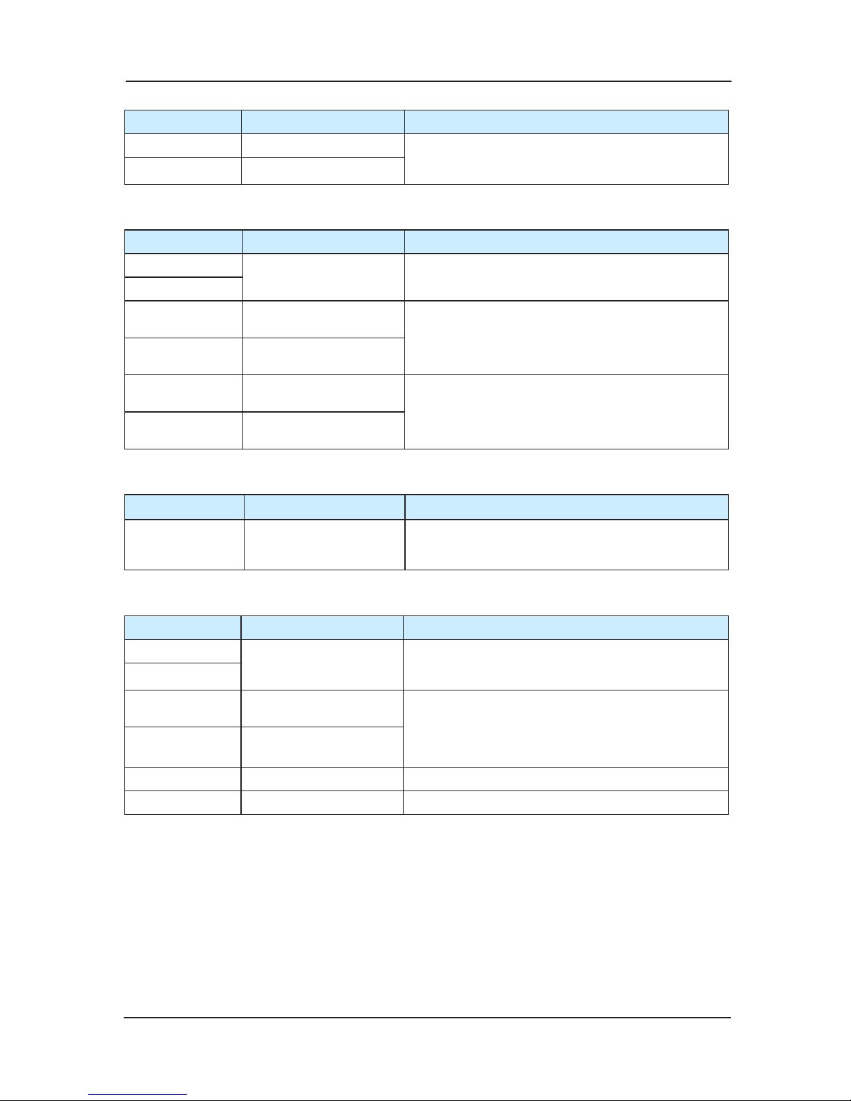
NICE3000 User Manual Installation and wiring
75
Terminal Name Instruction
Ai simulate input terminal terminal for simulation input,-10~10V,for weighing
device
M
DC 0V power
Plug CN3 instruction:e)
Terminal Name Instruction
24V
External DC24V input
Provide MCTC-MCB-A with DC24V, for input, output
circuit and communication circuit
COM
MOD+
Modbus communication
terminal
Display control board Seriall communication signal
feedback.
STP recommended.
MOD-
Modbus communication
terminal
CAN+
CAN bus communication
terminal
Used for CAN communication between MCTCMCB-A and MCTC-CTB-A. STP recommended.
CAN-
CAN bus
communication
terminal
Plug CN7 instruction:f)
Terminal Name Instruction
Y1~M1 Y2~M2
Y3~M3 Y4~M4
Y5~M5 Y6~M6
relay output function
selection
The relay normal open contact outputs 5A,
250VAC, and corresponding function code is
decided by F5-26 ~F5-31.
Plug CN6 encoder interface terminal instruction:g)
Terminal Name Instruction
15V
DC15V output
Provide DC15V for encoder, suit for incremental
push-pull output or incremental plough collector
output.
PGM
PGA
coding pulse input A
phase
Incremental coding pulse signal inputting,
frequency dividing signal input A phase and B
phase in IP motor, Type MCTC-PG-B.
The system will show the fault of encoder if A
phase and B phase are wrongly connected.
PGB
coding pulse
input B
phase
PGM DC15 0V terminal MCTC-PG-B grounding terminal
PE Grounding terminal Encoder wire shield layer
And CN12 is interface for operation panel, CN2 is interface for computer monitor.
Page 76
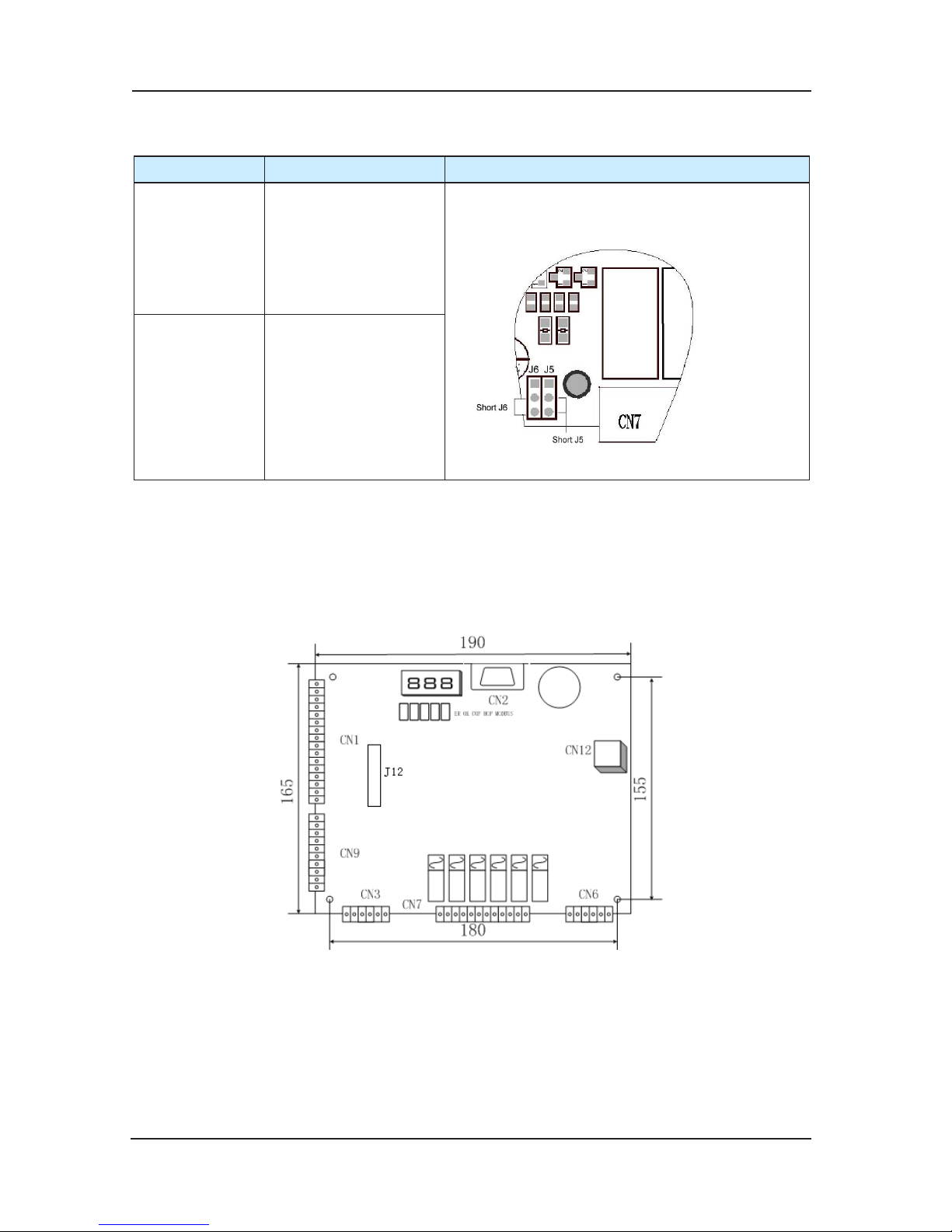
Installation and wiring NICE3000 User Manual
76
jumper J5、J6 instruction (Except for VER A, VER B, VER C)h)
Terminal Name Instruction
JP5
CAN communication
matching resistance
jumper
Short J5,
inner calling communication circuit will be
connected with internal resistance
Short J6, outer calling communication circuit will be
connected with internal resistance.
J6
Outer calling matching
resistance jumper
MCTC-MCB-B main control board electric wiring instruction3)
MCTC-MCB-B has all the function of MCTC-MCB-A and changes on the hardware’s structure.
Meanwhile it adds one slot J12 with 28 holes to match the use of PG card PG-D and PG-E. The
specific instruction will be in
troduced in PG-D and PG-E.
Main control board installation size:a)
Chart 4-6 Main control board installation size of MCTC-MCB-B
The main control board’s indicator, terminal interface, and use of MCTC-MCB-B is the same
with that of MCTC-MCB-A and can refer to the instruction book of MCTC-MCB-A.
MCTC-MCB-B is the advanced product of MCTC-MCB-A and will replace it.
Page 77
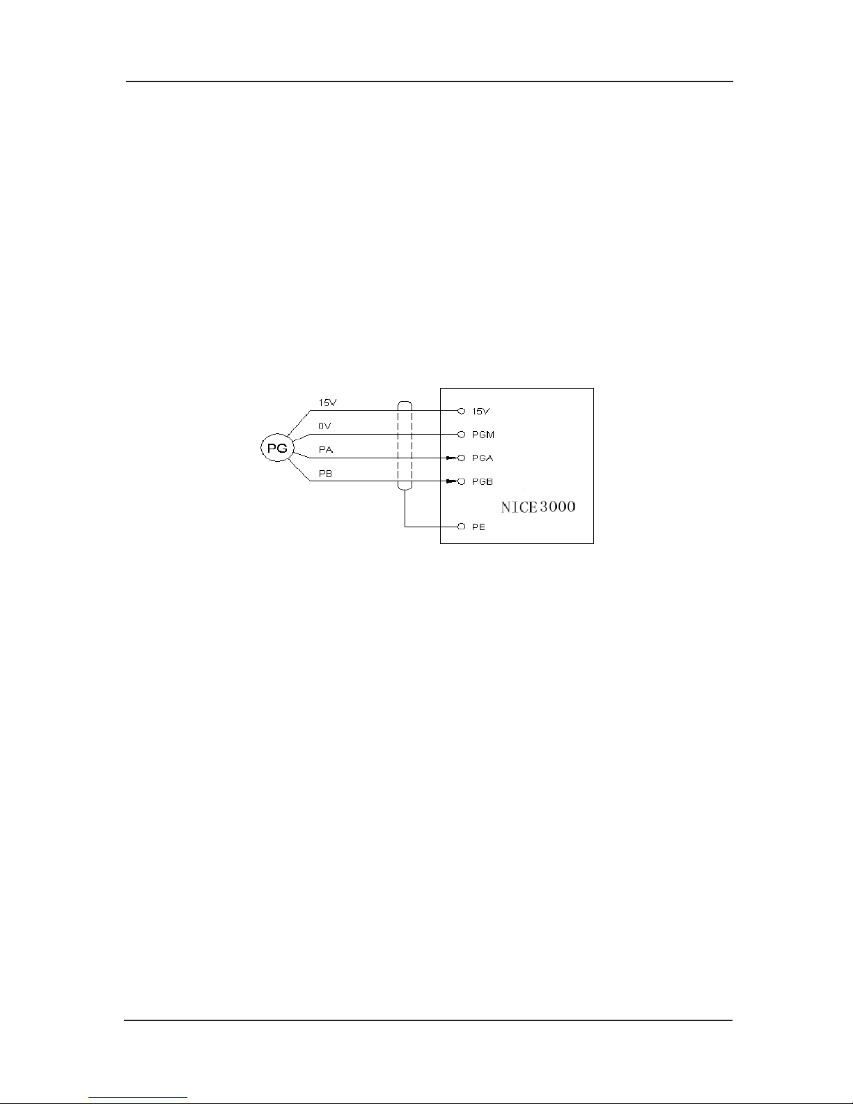
NICE3000 User Manual Installation and wiring
77
Encoder wiring4)
Following items should be noticed in encoder wiring:a)
PG wire should be laid separately and keep distance from control circuit and driver circuit
and forbidden to parallel with them.
PG wire should be shield wire, and shield layer should connect to PE near controller. (In
order to avoid being disturbed, only one terminal connects to ground.)
PG wire should be pulled on pipe sep
arately, and metal crust should be connected to
ground credibility.
Encoder connection as follows:b)
Encoder connection of increment push-pull output and open collector output.
MCTC-MCB-A/B self-equipped with push-pull encoder trans-connection circuit. Its connection
is as follows:
Chart 4-7 connection of increment push-pull output and plough collector output encoder
Type U, V, W encoder wiringc)
For type UVW encoder, the controller of the main control board with the type MCTC-MCB-A
needs to equip with PG connection card MCTC-PG-B; the controller of the main control board
with the type MCTC-MCB-B needs to equip with PG connection card MCTC-PG-B and needs
to equip with MCTC-PG
-D through the slot J12 on the main control board.
Terminal instruction of MCTC-PG-B card
There are 15 user connection terminals and 16 pin interfaces with two lines, referring to
chart3-8. VCC and GND supply the encoder with work power; A+、A-、B+、B-、U+、
U-、V+、V-、W+、W- are encoder’s signal inputting terminal; COM, OUT-A, OUT-B are
frequency division signal outputting terminals; 16 pin interfaces con
nect to the bottom drive
board of the controller.
Page 78
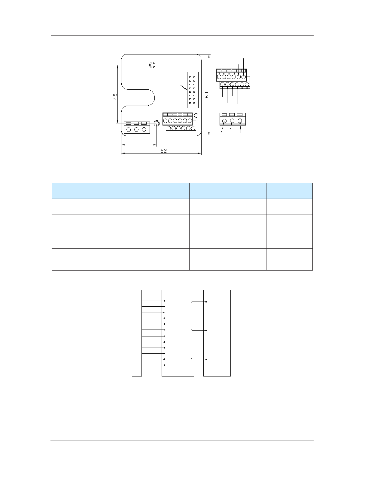
Installation and wiring NICE3000 User Manual
78
OUT-B
OUT-A
COM
22
A+
B+
GND
W-V-U-
U+
V+
W+
VCC
B-
A-
接至底层驱动板
Connect to the bottom
layer of the control
board
Chart 4-8 MCTC-PG-B sketch
MCTC-PG-B technique data
Function
Responding
speed
Output
impedance
Output
current
Frequency
division range
VCC,GND
Encoder power
supply
--- About 300Ω 300mA ---
A+,B+,
A-,B-,
U+,V+,
W+, U-,
V-,W-
Encoder signal
input
0~80 kHz --- --- ---
OUT-A,
OUT-B,
COM
Frequency
division output
0~80 kHz About 300Ω 100mA 1
The wiring of MCTC-PG-B and UVW encoder is shown as follows:
NICE 3000
PGA
PGB
PGM
OUT-B
OUT-A
COM
5V+
0v
A
+
A
-
B
+
B
-
B
-
B
+
A
-
A
+
P
G
U
+
U
-
V
+
V
-
W
+
W
-
U
-
V
+
V
-
W
+
W
-
VCC
GND
U
+
MCTC-PG-B
Fig 4-9 MCTC-PG-B wiring
MCTC-PG-E appearance and installation
MCTC-PG-E is installed on the main control board through J1 (Two lines of 28 plugs), and
connected with SIN/COS encoder through CN1 interface. The appearance and installation size
are in the following chart4-10:
Page 79
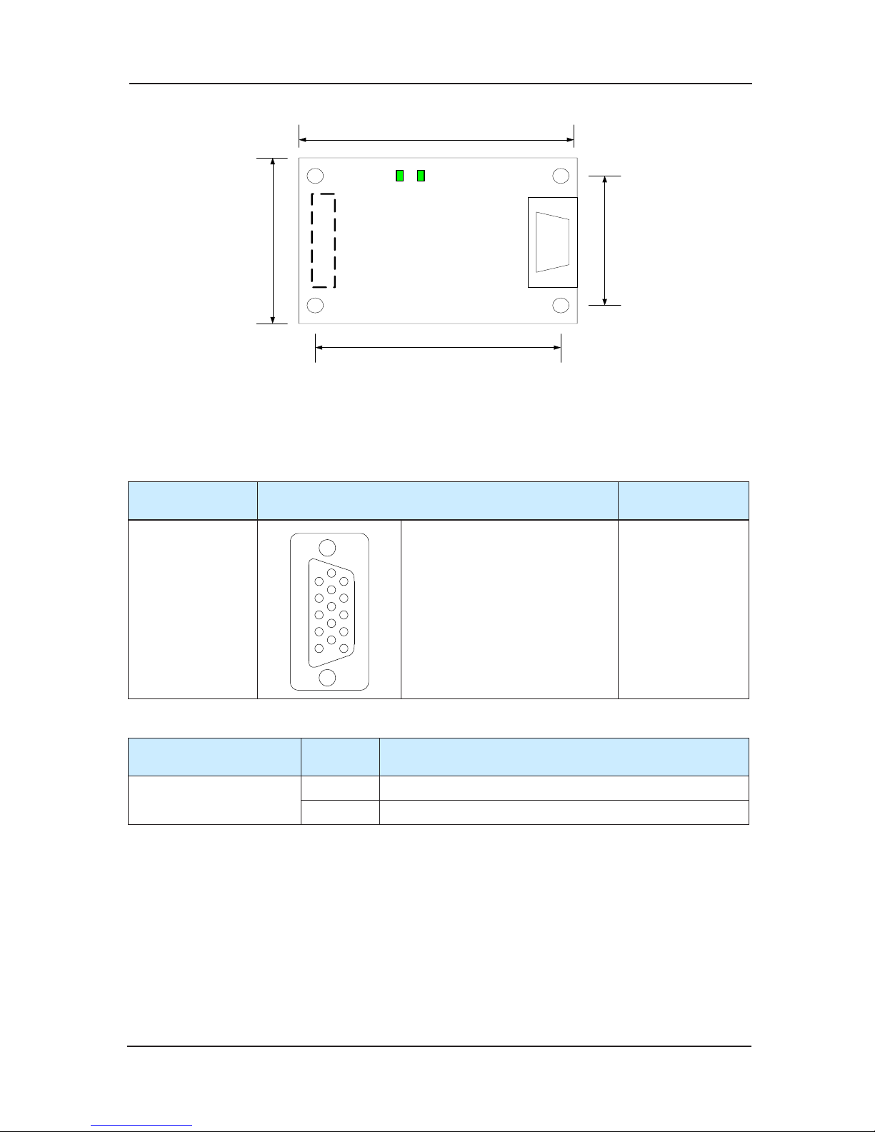
NICE3000 User Manual Installation and wiring
79
84
75
43
55
J1 CN1
MCTC-PG-E
D11 D8
Fig 4-10 MCTC-PG-E appearance and size
MCTC-PG-E wiring instruction
The CN1 terminal of MCTC-PG-E is connected with SIN/COS encoder with Type D 15 pins
(DB15) connector. The meaning of each pin of the connector is as follows:
Type of PG trans-
connection card
The meaning of DB15’s each pin Suitable encoder
MCTC-PG-E
1
6
5
10
15
11
1:B- 2:NC 3:Z+
4:Z- 5:A+ 6:A-
7:COM 8:B+ 9:VCC
10:C+ 11:C- 12:D+
13:D- 14:NC 15:NC
SIN/COS encoder
Instruction of MCTC-PG-E indicator:
Type of PG trans-
connection card
Number Function description
MCTC-PG-E
D8 B+/B-Differential signal indicator, ash while running
D11 A+/A-Differential signal indicator, ash while running
Page 80

Installation and wiring NICE3000 User Manual
80
Page 81

5
Function parameters tables
Page 82

Function parameters tables NICE3000 User Manual
82
Chapter 5 Function parameters tables
5.1 Function parameters Indication
Its function parameters are classified into 17 groups. Each function group1)
has several function codes. The function code adopts the 3
rd
level menu in the form of F X-XX.
In the manual it means No. XX function code in group X. For example, “F 8-08” means No.8
function code in group F8.
In order to make it convenient for function
code setting, when conducting operation via
operation panel, the function group number corresponds to the first level menu, the function
code number corresponds to the second level menu, and function code parameters correspond
to the third level menu.
Contents in the function tables:2)
In column 1, “Function code” means the code for the function parameter group and the
parameter; “Name” in column 2
means the complete name of the function parameter;
“Setting range” in column 3 means the valid parameter setting range, displaying on the
LED indicator of operation panel; “Min. Unit” in column 4 means the minimum unit of the
parameter setting; “Default” in column 5 means the original default; “Modification” in
column 6 means the modification attributes of the parameters (i.e. whether to enable t
he
modification and the modification requirements) :
‘☆’: the parameter can be modified while the NICE3000 is running or stopping;
‘★’: the parameter can not be modified while the NICE3000 is running;
‘●’: it is actually measured recorded parameter, which cannot be modified;
(The system has already set the modification attributes of the parameters to prevent the user
from making wrong modification to the pa
rameter.)
“Default” means the numeric value after the function code parameter is 3)
refreshed when recovering the default parameter; but the actual measured value or recorded
value will not be refreshed.
The controller provides function code with password protection to protect the4)
parameters more effectively (Detailed in Sector 4.2.4 of Chapter 4).
Page 83
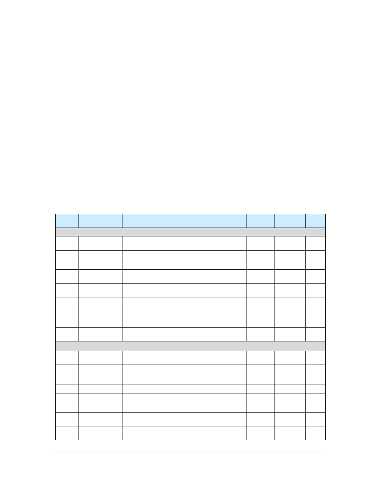
NICE3000 User Manual Function parameters tables
83
5.2 Function Parameters Tables
5.2.1 Groups of Function Parameters
Press UP/DOWN button after pressing “PRG”, all the first level menu displayed are the
groups of function. Details as follows:
F0——Basic parameters F9——Time parameters
F1——Motor parameters FA——Keyboard setting parameters
F2——Vector control parameters FB——Door function parameters
F3——Running control parameters FC——Protect function parameters
F4——Floor parameters FD——communication parameters
F5——Terminal function parameters FE——Lift function setting parameters
F6——Lift basic parameters FF——Factory parameters
F7——Testing function parameters FP——User parameters
F8——Reinforce function parameters
5.2.2 Parameters tables
Function
Code
Name Setting Range Min. Unit Default
Modifi-
cation
F0 Basic Parameters
F0-00 Control modes
0: Speed sensorless vector control(SVC)
1: Vector control(VC) with speed sensor
1 1 ★
F0-01
Command
source
selection
0:Operating panel command channel
1:Distance control
1 1 ★
F0-02
Operating panel
speed
0.050~F0-04 0.001m/s 0.050m/s ☆
F0-03
Elevator Max.
running speed
0.250~F0-04 0.001m/s 1.600m/s ★
F0-04
Elevator rated
speed
0
.250~4.000m/s 0.001m/s 1.600m/s ★
F0-05 Lift rated load 300~9999 kg 1 kg 1000 kg ★
F0-06 Max. frequency 20.00Hz~99.00Hz 0.01Hz 50.00Hz ★
F0-07
Carrier
frequency
0.5~16.0kHz 0.1kHz 6kHz ☆
F1 Motor Parameters
F1-00
Encoder type
selection
0: SIN/COS increment (ERN 1387)
1: UVW increment
1 1 ★
F1-01 Rated power 1.1~75.0kW 0.1kW
Depending
on the
model
★
F1-02 Rated voltage 0~440V 1V 380V ★
F1-03 Rated current 0.00~655.00A 0.01A
Depending
on the
mo
del
★
F1-04
Rated
frequency
0.00~99.00Hz 0.01Hz 50.00Hz ★
F1-05
Rated rotation
speed
0~3000rpm 1 rpm 1460 rpm ★
Page 84
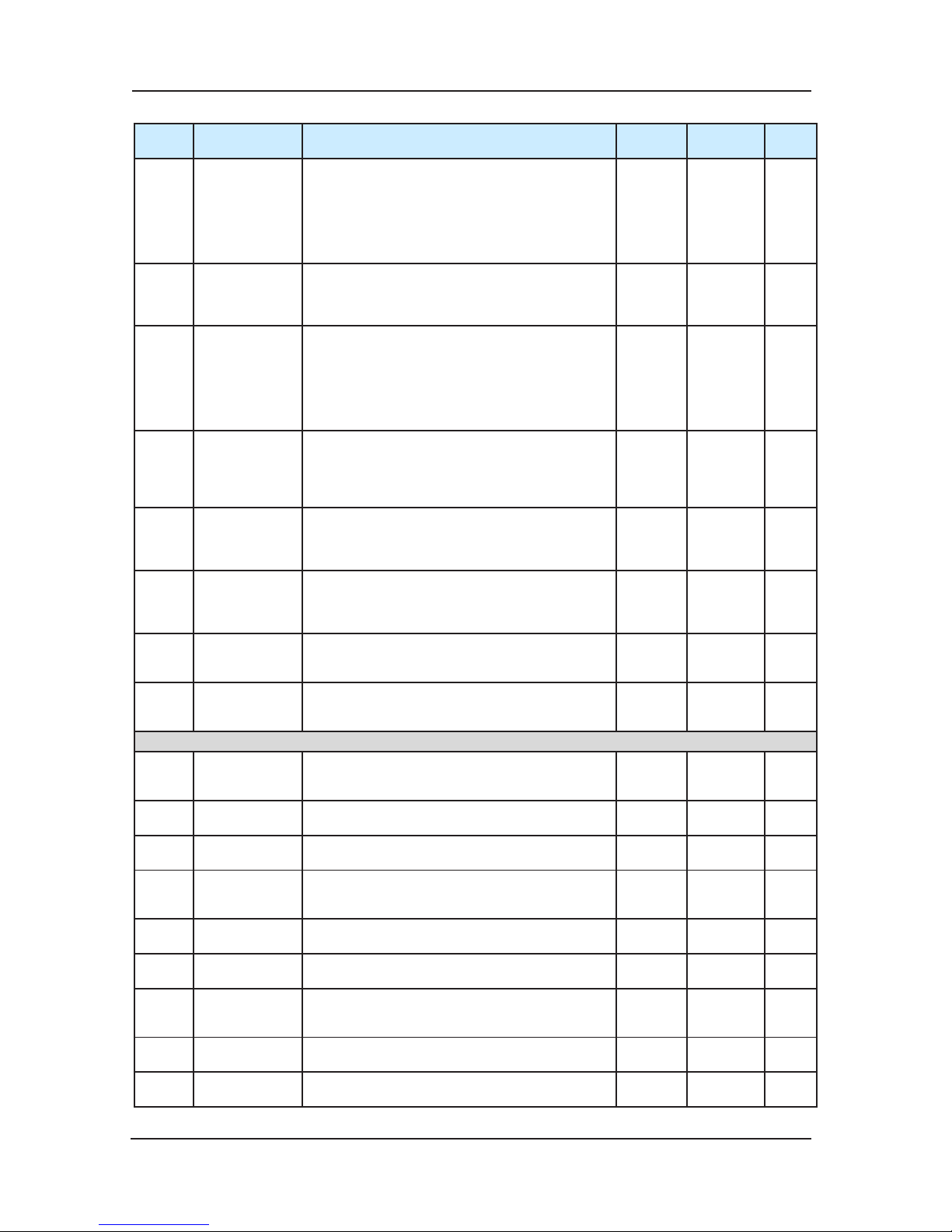
Function parameters tables NICE3000 User Manual
84
Function
Code
Name Setting Range Min. Unit Default
Modifi-
cation
F1-06
Stator resistance
(Asynchronous
motor)
Encoder original
angle
(Synchronous
motor)
0.000~30.000Ω
0~359.9°
0.001Ω
0.1°
Depending
on the
model
☆
F1-07
Rotor
resistance
Power-removal
angle (sync)
0.000~30.000Ω
0-359.9
0.001Ω
0.1
Depending
on the
model
☆
F1-08
Leakage
inductance
(Asynchronous
motor)
Wire connection
(Synchronous
motor)
0.00~300.00mH
0~15
0.01mH
0.
01
Depending
on the
model
☆
F1-09
Mutual
inductance
ADC sampling
delay
function(sync)
0.1~3000.0mH
0.00-40.00
0.1mH
0.00
Depending
on the
model
☆
F1-10
No-load current
Encoder test
selection(sync
motor)
0.01~300.00A
0~31
0.01A
01
Depending
on the
model
☆
F1-11
Auto-tuning
selection
0:No operation
1:motor tuning with load
2:motor tuning without load
3: shaft auto-tuning
1 0 ★
F1-12
Encoder pulse
number per
rotation
0~10000 1 1024
★
F1-13
Encode failure
monitoring
times
0.0~10.0s
Less than 1s, monitoring function not valid
0.1s 2.1s ★
F2 Vector Control Parameters
F2-00
Proportional
gain 1 of speed
loop
0~100 1 40 ☆
F2-01
Integration time
1 of speed loop
0.01~10.00s 0.01S 0.60S ☆
F2-02
Switching
frequency 1
0.00~F2-05 0.01Hz 2.00Hz ☆
F2-03
Proportional
gain 2 of speed
loop
0~100 1 35 ☆
F2-04
Integration time
2 of speed loop
0.01~10.00s 0.01s 0.80s ☆
F2-05
Switchin
g
frequency 2
F2-02~F0-06 0.01Hz 5.00Hz ☆
F2-06
Proportional
gain of current
loop
10~500 1 60 ☆
F2-07
Integral gain of
current loop
10~500 1 30 ☆
F2-08
Upper limit of
torque
0.0~200.0% 0.1% 150.0% ☆
Page 85
NICE3000 User Manual Function parameters tables
85
Function
Code
Name Setting Range Min. Unit Default
Modifi-
cation
F2-10
Lift Running
direction
0:same direction
1:reverse running direction, reverse position
impulse direction
2:same running direction, reverse impulse
direction
3:reverse running direction, same impulse
direction
1 0 ☆
F3 Running Control Parameters
F3-00 Start speed 0.000~0.030m/s 0.001m/s 0.010m/s ★
F3-01 Time keeping 0.000~0.500s 0.001s 0.150s ★
F3-02 Acceler
ation 0.200~2.000m/s
2
0.001m/s20.600m/s2★
F3-03
Inexion
speedup time 1
0.300~4.000s 0.001s 2.500s ★
F3-04
Inexion
speedup time 2
0.300~4.000s 0.001s 2.500s ★
F3-05 Deceleration 0.200~2.000m/s
2
0.001m/s20.600m/s2★
F3-06
Inexion slow-
down time 1
0.300~4.000s 0.001s 2.500s ★
F3-07
Inexion slow-
down time 2
0.300~4.000s 0.001s 2.500s ★
F3-08
Special
deceleration
0.500~2.000m/s
2
0.001m/s20.900m/s2★
F3-09
Pre-distance of
stop
0~90.0mm 0
.1mm 0.0mm ★
F3-10
Re-leveling
speed
0.000~0.080 m/s 0.001 m/s 0.040m/s ★
F3-11
Speed of slow
running
0.100~0.630 m/s 0.001 m/s 0.250m/s ★
F3-12
Switching
position of the
NO.1 up force
reducer
0.00~300.00m 0.01m 0.00m ★
F3-13
Switching
position of the
NO.1 down
force reducer
0.00~300.00m 0.01m 0.00m ★
F3-14
Switching
position of the
NO.2 up force
reducer
0.00~300.00m 0.01m 0.00m ★
F3-15
Switching
position of the
NO.2 down
force re
ducer
0.00~300.00m 0.01m 0.00m ★
F3-16
Switching
position of the
NO.3 up force
reducer
0.00~300.00m 0.01m 0.00m ★
F3-17
Switching
position of the
NO.3 down
force reducer
0.00~300.00m 0.01m 0.00m ★
F3-18
Output time of
starting zero
speed
0.000~1.000s 0.001s 0.200s ★
F3-19
Time-lag of
curve running
0.000~1.000s 0.001s 0.200s ★
Page 86
Function parameters tables NICE3000 User Manual
86
Function
Code
Name Setting Range Min. Unit Default
Modifi-
cation
F3-20
Time-lag of end
running
0.000~1.000s 0.001s 0.300s ★
F4 Floor Position Parameters
F4-00
Leveling
adjusting
0~60mm 1mm 30mm ★
F4-01 Current oor F6-01~F6-00 1 1 ★
F4-02
High bit of
current oor
0~65535 1 1 ●
F4-03
Low bit of
current oor
0~65535 1 34464 ●
F4-04
High bit of
leveling plate
0~65535 1 0 ★
F4-05
Low bit of
leveling plate
0~65535 1 0 ★
F4-06
High bit of oor
high 1
0~
65535 1 0 ★
F4-07
Low bit of oor
high 1
0~65535 1 0 ★
F4-08
High bit of oor
high 2
0~65535 1 0 ★
F4-09
Low bit of oor
high 2
0~65535 1 0 ★
F4-10
High bit of oor
high 3
0~65535 1 0 ★
F4-11
Low bit of oor
high 3
0~65535 1 0 ★
F4-12
High bit of oor
high 4
0~65535 1 0 ★
F4-13
Low bit of oor
high 4
0~65535 1 0 ★
F4-14
High bit of oor
high 5
0~65535 1 0 ★
F4-15
Low bit of oor
high 5
0~65535 1 0 ★
F4-16
High bit of oor
high 6
0~65535 1 0 ★
F4-17
Low bit of
oor
high 6
0~65535 1 0 ★
F4-18
High bit of oor
high 7
0~65535 1 0 ★
F4-19
Low bit of oor
high 7
0~65535 1 0 ★
F4-20
High bit of oor
high 8
0~65535 1 0 ★
F4-21
Low bit of oor
high 8
0~65535 1 0 ★
F4-22
High bit of oor
high 9
0~65535 1 0 ★
F4-23
Low bit of oor
high 9
0~65535 1 0 ★
F4-24
High bit of oor
high 10
0~65535 1 0 ★
F4-25
Low bit of oor
high 10
0~65535 1 0 ★
Page 87
NICE3000 User Manual Function parameters tables
87
Function
Code
Name Setting Range Min. Unit Default
Modifi-
cation
F4-26
High bit of oor
high 11
0~65535 1 0 ★
F4-27
Low bit of oor
high 11
0~65535 1 0 ★
F4-28
High bit of oor
high 12
0~65535 1 0 ★
F4-29
Low bit of oor
high 12
0~65535 1 0 ★
F4-30
High bit of oor
high 13
0~65535 1 0 ★
F4-31
Low bit of oor
high 13
0~65535 1 0 ★
F4-32
High bit of oor
high 14
0~65535 1 0 ★
F4-33
Low bit of oor
high 14
0~65535 1 0 ★
F4-34
High bit of oor
high 15
0~655
35 1 0 ★
F4-35
Low bit of oor
high 15
0~65535 1 0 ★
F4-36
High bit of oor
high 16
0~65535 1 0 ★
F4-37
Low bit of oor
high 16
0~65535 1 0 ★
F4-38
High bit of oor
high 17
0~65535 1 0 ★
F4-39
Low bit of oor
high 17
0~65535 1 0 ★
F4-40
High bit of oor
high 18
0~65535 1 0 ★
F4-41
Low bit of oor
high18
0~65535 1 0 ★
F4-42
High bit of oor
high 19
0~65535 1 0 ★
F4-43
Low bit of oor
high 19
0~65535 1 0 ★
F4-44
High bit of oor
high 20
0~65535 1 0 ★
F4-45
Low bi
t of oor
high 20
0~65535 1 0 ★
F4-46
High bit of oor
high 21
0~65535 1 0 ★
F4-47
Low bit of oor
high 21
0~65535 1 0 ★
F4-48
High bit of oor
high 22
0~65535 1 0 ★
F4-49
Low bit of oor
high 22
0~65535 1 0 ★
F4-50
High bit of oor
high 23
0~65535 1 0 ★
F4-51
Low bit of oor
high 23
0~65535 1 0 ★
F4-52
High bit of oor
high 24
0~65535 1 0 ★
Page 88
Function parameters tables NICE3000 User Manual
88
Function
Code
Name Setting Range Min. Unit Default
Modifi-
cation
F4-53
Low bit of oor
high 24
0~65535 1 0 ★
F4-54
High bit of oor
high 25
0~65535 1 0 ★
F4-55
Low bit of oor
high 25
0~65535 1 0 ★
F4-56
High bit of oor
high 26
0~65535 1 0 ★
F4-57
Low bit of oor
high 26
0~65535 1 0 ★
F4-58
High bit of oor
high 27
0~65535 1 0 ★
F4-59
Low bit of oor
high 27
0~65535 1 0 ★
F4-60
High bit of oor
high 28
0~65535 1 0 ★
F4-61
Low bit of oor
high 28
0~6553
5 1 0 ★
F4-62
High bit of oor
high 29
0~65535 1 0 ★
F4-63
Low bit of oor
high 29
0~65535 1 0 ★
F4-64
High bit of oor
high 30
0~65535 1 0 ★
F4-65
Low bit of oor
high 30
0~65535 1 0 ★
F4-66 reserved 0~65535 1 0 *
F4-67 reserved 0~65535 1 0 *
F5 Terminal Function Parameters
F5-00
ATT/Normal
switching time
3~200s 1 3s ★
Page 89
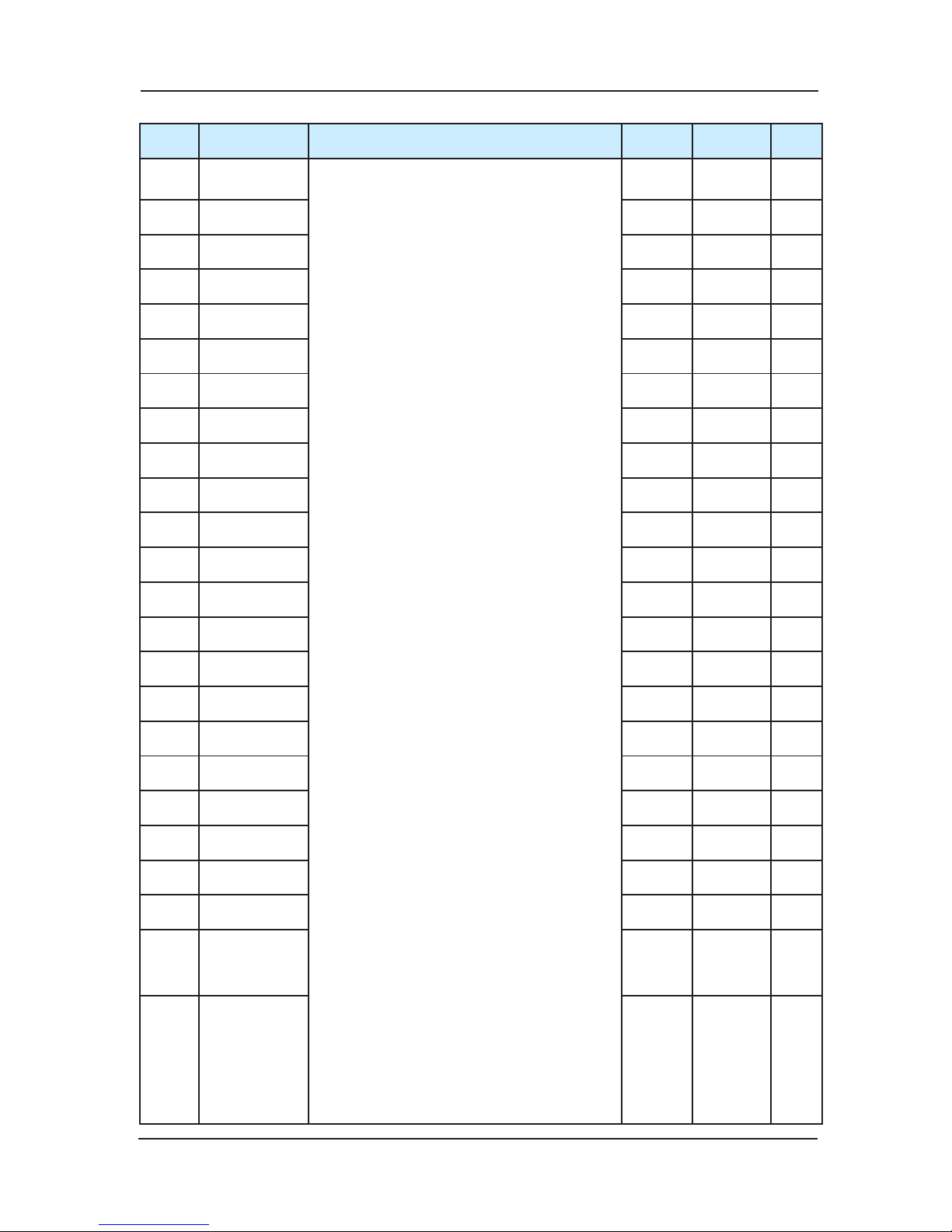
NICE3000 User Manual Function parameters tables
89
Function
Code
Name Setting Range Min. Unit Default
Modifi-
cation
F5-01
Select function
of terminal X1
00:No function
01:N.O. input of up leveling
02:N.O. input of down leveling
03:N.O. input of door zone
04:N.O. input of Safety circuit feedback
05:N.O. input of Lock circuit feedback
06:N.O. input of running output feedback
07:N.O. input of brake output feedback
signal
08:N.O. input of inspection signal
09:N
.O. input of inspection up
10:N.O. input of inspection down
11:N.O. input of fire signal
12:N.O. input of upper limit signal
13:N.O. input of lower limit signal
14:N.O. input of over loading
15:N.O. input of full load
16:N.O. input of NO.1 up force reducer
17:N.O. input of NO. 1 down force reducer
18:N.O. input of NO.2 up force reducer
19:N.O. input of NO. 2 down force reducer
20:N.O. input of NO.3 up
force reducer
21:N.O. input of NO. 3 down force reducer
22:advanced door-opening module output
feedback N/O input
23: N.O. input of firemen opening and
closing
24:N.O. input of door motor light-beam
curtain1
25:N.O. input of door motor light-beam
curtain2
26:N.O. input of brake output feedback 2
27:Valid N.O. input of UPS
28:N.O. input of lift-locking
29 : N.O. input 2 of safety signal
30 : N.O. input of
synchronous motor U,V,W
jump-out feedback
31 : N.O. input of door lock circuit2 feedback
33:N.C. input of up leveling
34:N.C. input of down leveling
35:N.C. input of door zone
36:N.C. input of Safety circuit feedback
37: N.C. input of Lock circuit feedback
38:N.C. input of running output feedback
39: N.C. input of brake contactor feedback
signal
40:N.C. input of inspection signal
41:N.C. input of inspectio
n up
42:N.C. input of inspection down
43:N.C. input of fire signal
44:N.C. input of upper limit signal
45:N.C. input of lower limit signal
46:N.C. input of over loading
47:N.C. input of full loading
48:N.C. input of NO.1 up forced deceleration
49:N.C. input of NO. 1 down forced
deceleration
50:N.C. input of NO.2 up forced deceleration
51:N.C. input of NO. 2 down forced
deceleration
52:N.C. input of
NO.3 up forced deceleration
53:N.C. input of NO. 3 down forced
deceleration
54:N.C. input of advanced door-opening
module feedback
55: N.C. input of firemen opening and closing
56:N.C. input of door motor light-beam
curtain1
57:N.C. input of door motor light-beam
curtain2
58:N.C. input of brake output feedback2
59:Valid N.C. input of UPS
60 : N.C. input of lift-locking signal
61 : N.C. input 2 of safety
signal
62 : N.C. input of synchronous motor U,V,W
jump-out feedback
63 : N.C. input of door lock circuit 2 feedback
1 33 ★
F5-02
Select function
of terminal X2
1 35 ★
F5-03
Select function
of terminal X3
1 34 ★
F5-04
Select function
of terminal X4
1 04 ★
F5-05
Select function
of terminal X5
1 05 ★
F5-06
Select function
of terminal X6
1 38 ★
F5-07
Select function
of terminal X7
1 39 ★
F5-08
Select function
of terminal X8
1 22 ★
F5-
09
Select function
of terminal X9
1 40 ★
F5-10
Select function
of terminal X10
1 09 ★
F5-11
Select function
of terminal X11
1 10 ★
F5-12
Select function
of terminal X12
1 44 ★
F5-13
Select function
of terminal X13
1 45 ★
F5-14
Select function
of terminal X14
1 48 ★
F5-15
Select function
of terminal X15
1 49 ★
F5-16
Select function
of terminal X16
1 50 ★
F5-17
Select function
of terminal X17
1 51 ★
F5-18
Select function
of terminal X18
1 00 ★
F5-19
Select function
of terminal X19
1 00 ★
F5-20
Select function
of terminal X20
1 00 ★
F5-21
Select function
of terminal X21
1 00 ★
F5-22
Select function
of terminal X22
1 00 ★
F5-23
Select function
of terminal X23
1 00 ★
F5-24
Select function
of terminal X24
1 00 ★
Page 90
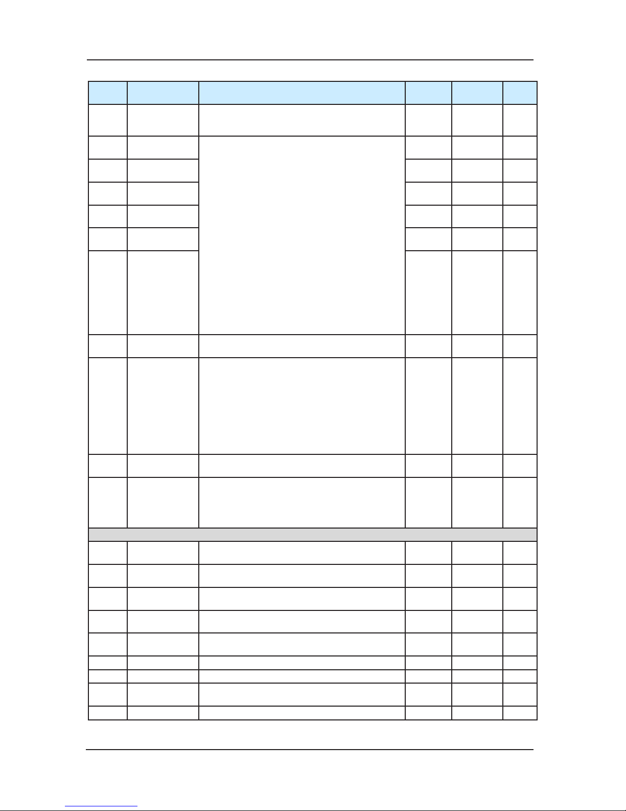
Function parameters tables NICE3000 User Manual
90
Function
Code
Name Setting Range Min. Unit Default
Modifi-
cation
F5-25
Car top board
input type
selection
0~255 1 64 ★
F5-26
Select function
of terminal Y1
0:No function
1:Run contactor output
2:Brake contactor output
3:advanced door-opening module output
4:Fire arrival landing signal feedback
5:Door motor 1 open
6:Door motor 1 close
7:Door motor 2 open.
8:Door motor 2 close
9:Brake, run contactor normal
10:Failure state
11:Run monitor
12:Synchronous motor U,V,W jump-out
output
13:Power failure emergency running
switching automatically
14:System normal
15: Emergency buzzer output
16: Brake forced output
17: elevator up running mark
18: illustration and fan output
1 1 ★
F5-27
Select function
of terminal Y2
1 2 ★
F5-28
Select function
of terminal Y3
1 3 ★
F5-29
Select function
of terminal Y4
1 4 ★
F5-30
Select function
of terminal Y5
1 0 ★
F5-
31
Select function
of terminal Y6
1 0 ★
F5-32
Communication
state display
Bit 0-bit11 hall call communication state
Bit12-bit15 inside call communication state
●
F5-33
Program control
select
Bit 4: cancel the arrival gong at night
Bit 5: input function 25/57 for the mmotor
overheat input or earthquake detection
Bit 6: add 1 more time doo-lock break when
the inspection to normal
Bit 7: no error display on the
small keypad
Bit 8: remove the door-open call when dooropen limit
Bit 9: elevator stop when the brake feedback
is abnormal
1 0
F5-34
Terminal state
display
●
F5-36
Weighing input
selection
0:car top panel input and analogue input is
invalid
1:Car top panel switch input
2:Car top panel analog input
3:Main control panel analog sampling.
1 2 ★
F6 Lift Basic Parameters
F6-00
The highest
landing
F6-01~31 1 9 ★
F6-01
The lowes
t
landing
1~F6-00 1 1 ★
F6-02
Parking main
landing
F6-01~ F6-00 1 1 ★
F6-03
Fire main
landing
F6-01~F6-00 1 1 ★
F6-04
Lift lock main
landing
F6-01~F6-00 1 1 ★
F6-05 service oor 1 0~65535 (from 1st to 16th oor) 1 65535 ★
F6-06 service oor 2 0~65535 (from 17th to 31st oor) 1 65535 ★
F6-07
Group control
number
1~8 1 1 ★
F6-08 Lift number 1~8 1 1 ★
Page 91
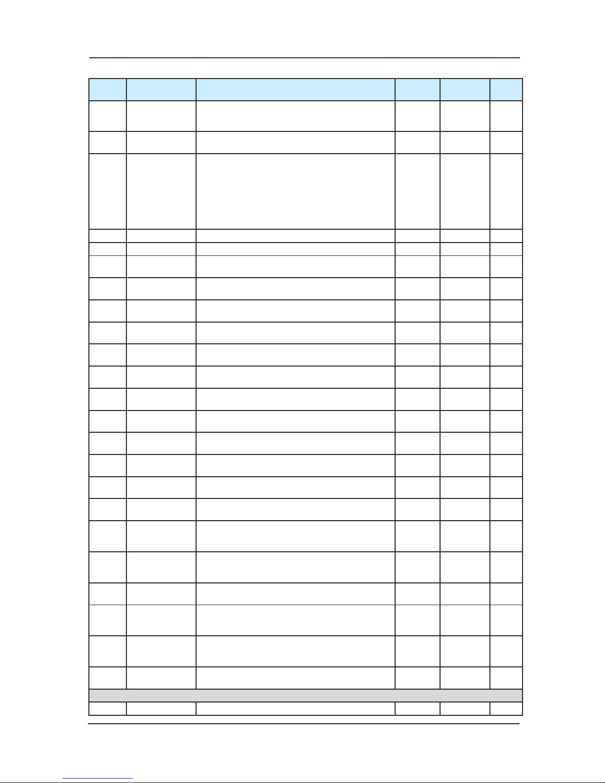
NICE3000 User Manual Function parameters tables
91
Function
Code
Name Setting Range Min. Unit Default
Modifi-
cation
F6-09
Parallel
selection
Bit0:separate stay function
Bit1: reserved
Bit2:Parallel in monitor contactor
1 0 ★
F6-10
Leveling sensor
delay time
10~50ms 1 14ms ★
F6-11
Elevator
function
selection
Bit4: stop 300 ms current bias mode
Bit5:synchronous motor startup current detect
function
Bit7: inspection non-door zone opening is valid
Bit8: first power-apply, open
for once when it is
normal
Bit10: reversal-leveling buzzer is not sound
Bit13: E53 error auto reset
1 0 ★
F6-12 VIP oor 0- highest oor (F6-00) 1 0 ★
F6-13 Security oor F6-01~F6-00 1 1 ☆
F6-14
down-collective
1 start time
00.00~23.59(hr.min.) 00.01 00.00 ☆
F6-15
down-collective
1 end time
00.00~23.59(hr.min.) 00.01 00.00 ☆
F6-16
down-collective
2 start time
00.00~23.59(hr.min.) 00.01 00.00 ☆
F6-17
down-collective
2 end tim
e
00.00~23.59(hr.min.) 00.01 00.00 ☆
F6-18
Time-sharing
service 1 start
00.00~23.59(hr.min.) 00.01 00.00 ☆
F6-19
Time-sharing
service 1 end
00.00~23.59(hr.min.) 00.01 00.00 ☆
F6-20
Time-sharing
service 1 oor 1
0~65535 (from 1st to 16th oor) 1 65535 ☆
F6-21
Time-sharing
service 1 oor 2
0~65535 (from 17th to 31 st oor) 1 65535 ☆
F6-22
Time-sharing
service 2 start
00.00~23.59(hr.min.) 00.01 00.00 ☆
F6-23
Time-sharing
service 2
end
00.00~23.59(hr.min.) 00.01 00.00 ☆
F6-24
Time-sharing
service 2 oor 1
0~65535 (from 1st to 16th oor) 1 65535 ☆
F6-25
Time-sharing
service 2 oor 2
0~65535 (from 17th to 31 st oor) 1 65535 ☆
F6-26
Parallel
fastigium 1 start
time
00.00~23.59(hr.min.) 00.01 00.00 ☆
F6-27
Parallel
fastigium 1 end
time
00.00~23.59(hr.min.) 00.01 00.00 ☆
F6-28
Parallel
fastigium oor 1
F6-01~F6-00 1 1 ☆
F6-29
Parallel
fastigium 2 start
time
00.0
0~23.59(hr.min.) 00.01 00.00 ☆
F6-30
Parallel
fastigium 2 end
time
00.00~23.59(hr.min.) 00.01 00.00 ☆
F6-31
Parallel
fastigium oor 2
F6-01~F6-00 1 1 ☆
F7 Testing Function Parameters
F7-00 Test oor 1 0~the highest oor (F6-00) 1 0 ☆
Page 92
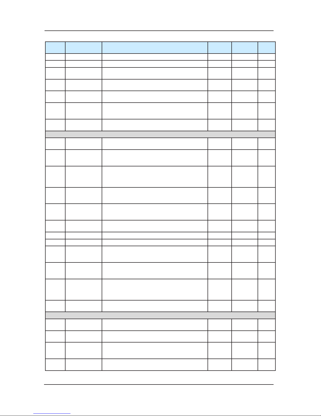
Function parameters tables NICE3000 User Manual
92
Function
Code
Name Setting Range Min. Unit Default
Modifi-
cation
F7-01 Test oor 2 0~the highest oor (F6-00) 1 0 ☆
F7-02 Test oor 3 0~the highest oor (F6-00) 1 0 ☆
F7-03
Test times at
random
0~60000 1 0 ☆
F7-04
Landing call
enable
0:Landing call allowable;
1:Landing call forbidden
1 0 ☆
F7-05
Door open
enable
0:Door open allow
1:Door open forbidden
1 0 ☆
F7-06
Overload
function
selection
0:Overload run forbidden
1:Overload run allowab
le
1 0 ☆
F7-07 Limit enable
0:End switch availability;
1:End switch invalidation
1 0 ☆
F8 Reinforce Function Parameters
F8-00
Weighing auto-
tuning
0~100% 1% 0% ★
F8-01
Pre-torque
selection
0:Pre-torque is invalid
1:weighing pre-torque compensation
2: automatic pre-torque compensation
1 0 ★
F8-02
Pre-torque bias,
Zero servo
current
coefficient
0.0~100.0%
0.20%~50.0%
0.1%
50.0%
15.0%
★
F8-03
Drive gain,
Zero servo
speed loop KP
0.00~
2.00
0.00~1.00
0.01
0.60
0.50
★
F8-04
Brake gain
Zero servo
speed loop TI
0.00~2.00
0.00~2.00
0.01
0.60
0.60
★
F8-05
Car load at
present
0~1023 1 0 ●
F8-06 Car no load set 0~1023 1 0 ★
F8-07 Car full load set 0~1023 1 100 ★
F8-08
Anti-nuisance
function
0:This function is forbidden;
1:Allowable (This function can be used with
weighing sensor available.)
1 0 ☆
F8-09
Power failure
emergency
rescue speed
0.000~0.100m/s 0.001m/s 0.050m/s ☆
F8-10
Po
wer failure
emergency
rescue
selection
0: no running
1: UPS power running
2: 48V battery power
1 0 ☆
F8-11
Stopping torque
output delay
0.200~1.500s 0.001 0.200 ☆
F9 Time Parameters
F9-00
Free return
main oor time
0~240min 1min 10min ☆
F9-01
Fan and light
closed time
0~240min 1min 2min ☆
F9-02
Longest interval
time of oor
running
0~45s (invalidation under 3s) 1s 45s ★
F9-03 Clock: year 2000~2100 1
Current
time
☆
Page 93
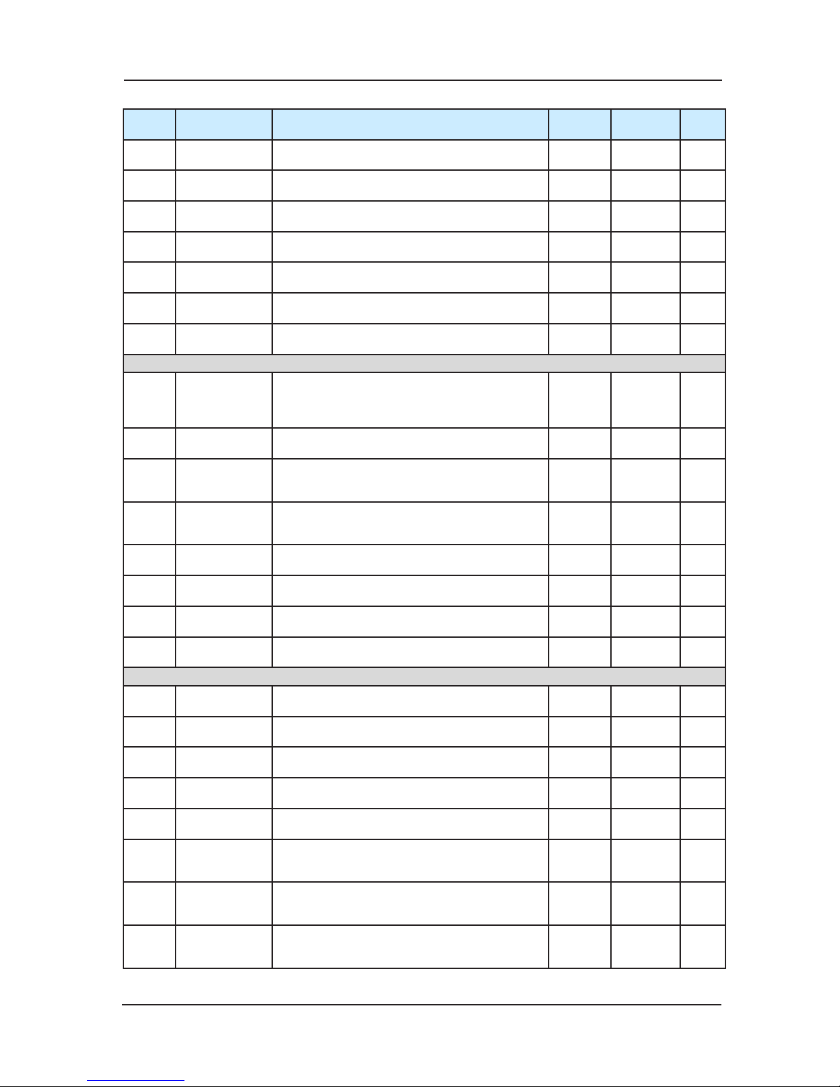
NICE3000 User Manual Function parameters tables
93
Function
Code
Name Setting Range Min. Unit Default
Modifi-
cation
F9-04 Clock: month 1~12 1
Current
time
☆
F9-05 Clock: day 1~31 1
Current
time
☆
F9-06 Clock: hour 0~23 1
Current
time
☆
F9-07 Clock: minute 0~59 1
Current
time
☆
F9-09
Accumulative
working time
0~65535hr. 1 0 ●
F9-11
Run times high
bit
0~9999
Note: 1 means actual 10000 run times
1 0 ●
F9-12
Run times low
bit
0~9999 1 0 ●
FA Keyboard Setting Parameters
FA-00
Small keyboard
displa
y
selection
0: Reversal display, physics oor
1:Positive display, physics oor
2:Reversal display, external call data
3:Positive display, external call data
1 0 ☆
FA-01
Running display
selection
1~65535 1 65535 ☆
FA-02
Stopping
display
selection
1~65535 1 65535 ☆
FA-03
Pulse wheel
encoder
currently angle
0.0~360.0° 0.1° 0.0° ●
FA-04
Software edition
1(FK)
0~65535 1 0 ●
FA-05
Software edition
2(ZK)
0~65535 1 0 ●
FA-06
Software edition
3
(DSP)
0~65535 1 0 ●
FA-07
Radiator
temperature
0~100℃ 1℃ 0 ●
FB Door Function Parameters
FB-00
door machine
number
1~2 1 1 ★
FB-02
Door machine1
service oor 1
0~65535(from 1st to 16th oor) 1 65535 ☆
FB-03
Door machine1
service oor2
0~65535(from 17th to 31st oor) 1 65535 ☆
FB-04
Door machine2
service oor1
0~65535(from 1st to 16th oor)only valid
when there are two door machines
1 65535 ☆
FB-05
Door machine2
service oor2
0~65535(
from 17th to 31st oor) only valid
when there are two door machines
1 65535 ☆
FB-06
Time protection
for opening the
door
5~99s 1s 10s ☆
FB-07
Arrival gong
output delayed-
time
0~1000ms 1ms 0 ☆
FB-08
Time protection
for closing the
door
5~99s 1s 15s ☆
Page 94
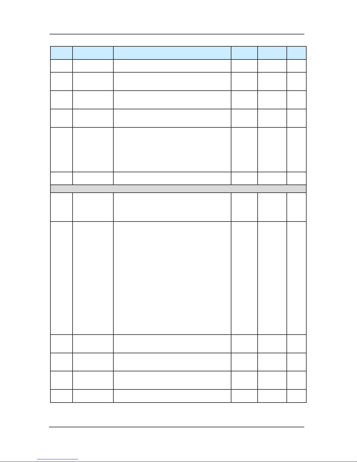
Function parameters tables NICE3000 User Manual
94
Function
Code
Name Setting Range Min. Unit Default
Modifi-
cation
FB-09
Door open/
close times
0~20 1 0 ☆
FB-10
Run main
landing door
state
0: open the door normally
1: waiting for opening the door
1 0
FB-11
Time keeping
for hall call door
opening
1~30s 1s 5s ☆
FB-12
Time keeping
for internal call
door opening
1~30s 1s 3s ☆
FB-13
Time keeping
for opening at
main landing
(main landing is
used including
Single Lift,
Group Control
,
and Lock Lift)
1~30s 1s 10s ☆
FB-14
Delay time for
open keeping
10~1000s 1s 30s ☆
FC Protect Function Parameters
FC-00
Earth short
circuit
protection
detection after
power on
0:Forbidden;
1:Allowable
1 1 ★
FC-01
Protection
selection
Bit0:Overload protection selection
0:Forbidden
1:Allowable
Bit1:Output phase-failure selection
0:Phase-failure protection
1:Phase-failure unprotected
Bit3: E053 add door-close limit judgment
0
:no new method
1:old method + old method
Bit4: door-closing limit judge light curtain
0:no re-opening
1:re-open the door
Bit5: DSP communication judgment
0:wire broken check
1:no check
Bit6: new method for parallel door block
0: use mew method
1: resume to 745 program
Bit7:reveling over-speed check
0:check
1:no check
1 1 ☆
FC-02
Overload
protection
coefficient
0.50~10.00 0.01 1.00 ☆
FC-03
Overload
pre-warning
coefficient
50~100% 1% 80% ☆
FC-04
Error self-
resetting times
0:Means that the system forbidden autoresetting function;
0~10
1 0 ★
FC-05
Reset interval
time
2~20s 1s 5s ★
Page 95

NICE3000 User Manual Function parameters tables
95
Function
Code
Name Setting Range Min. Unit Default
Modifi-
cation
FC-06
The first error
information
0~3199
Note: The first two figures mean the oor’s
number, and the last two mean the error code.
e.g. error 30 occurs in Floor1(the elevator’s
position is abnormal), the error information
displays 0130.
0: No error
1: Inverse unit protection
2: Over current accelerated
3: Over current decelerated
4: Over current cons
tant
5: Over voltage accelerated
6: Over voltage decelerated
7: Over voltage constant
8: Controller power fault
9: Under voltage fault
10:Controller overload
11: Motor overload
12: Input side phase loss
13: Output side phase loss
14: Module overheated
15: Reserved
16: Reserved
17:Contactor fault
18: Current detection fault
19: Motor tuning fault
20: Encoder fault
21: Synchronous motor encoder wiring error
22: Leve
ling inductor signal is abnormal
23: Short circuit fault to ground
24:Reserved
25: Data storage error
26~28: Reserved
29: Synchronous self-locking contactor
feedback is deviant
30: Lift position is deviant
31: DPRAM is deviant
32: CPU is deviant
33: Lift over speed error
34: Logic fault
35: shaft auto-tuning date is deviant
36: Contact feedback is deviant
37: Brake feedback is deviant
38: Controller encode sign
al is deviant
39: Motor overheated
40: Lift running condition is not satisfied
41: Safety circuit cut
42: Door lock cut when running
43: Upper limit signal cut when running
44: Lower limit signal cut when running
45: Up/Down force reducer switch cut
46: Re-leveling is deviant
47: Lock contactor is deviant
48: Door open fault
49: Door close fault
50: Group control communication fault
51: Inside call communicati
on fault
52: Outside call communication fault
53: Lock jump fault
1 0 ●
FC-07
The first error
month and day
0~1231 1 0 ●
FC-08
The second
error
information
0~3199 1 0 ●
FC-09
The second
error month and
day
0~1231 1 0 ●
Page 96
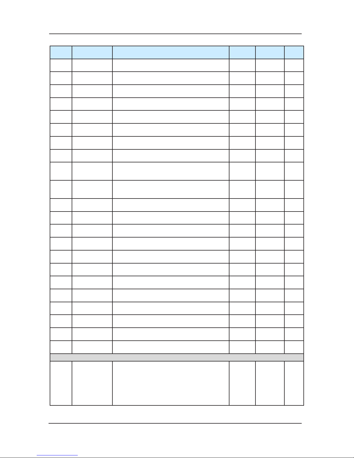
Function parameters tables NICE3000 User Manual
96
Function
Code
Name Setting Range Min. Unit Default
Modifi-
cation
FC-10
The third error
information
0~3199 1 0 ●
FC-11
The third error
month and day
0~1231 1 0 ●
FC-12
The fourth error
information
0~3199 1 0 ●
FC-13
The fourth error
month and day
0~1231 1 0 ●
FC-14
The fifth error
information
0~3199 1 0 ●
FC-15
The fifth error
month and day
0~1231 1 0 ●
FC-16
The sixth error
information
0~3199 1 0 ●
FC-17
The sixth error
month and day
0~1231 1 0 ●
FC-18
T
he seventh
error
information
0~3199 1 0 ●
FC-19
The seventh
error month and
day
0~1231 1 0 ●
FC-20
The eighth error
information
0~3199 1 0 ●
FC-21
The eighth error
month and day
0~1231 1 0 ●
FC-22
The ninth error
information
0~3199 1 0 ●
FC-23
The ninth error
month and day
0~1231 1 0 ●
FC-24
The tenth error
information
0~3199 1 0 ●
FC-25
The tenth error
month and day
0~1231 1 0 ●
FC -26
The last error
information
0~3199 1 1 ●
FC -27
Latest error
spee
d
0.000~3.000m/s 0.001m/s 0.000 ●
FC -28
Latest error
current
0.0~999.9A 0.1A 0.0 ●
FC-29
Latest error bus
voltage
0~999V 1V 0 ●
FC-30
Latest error
month and day
0~1231 1 0 ●
FC-31
Latest error
time
0~2359 1 0 ●
FD Communication Parameters
FD-00
Baud rate
setting
0:300bps
1:600bps
2:1200bps
3:2400bps
4:4800bps
5:9600bps
6:19200bps
7:38400bps
1 5 ★
Page 97
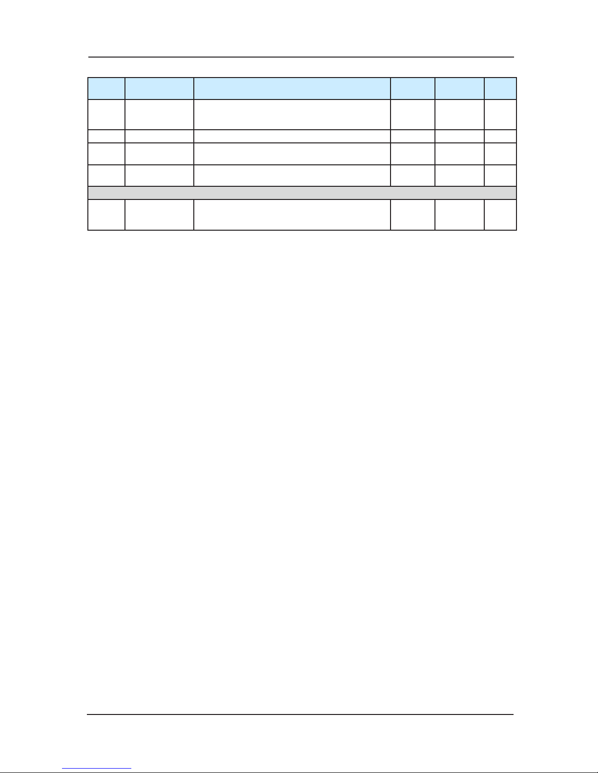
NICE3000 User Manual Function parameters tables
97
Function
Code
Name Setting Range Min. Unit Default
Modifi-
cation
FD-01 Data format
0: No check-out: Data format<8,N,2>
1: Even check-out: Data format<8,E,1>
2: Odd check-out: Data format<8,0,1>
1 0 ★
FD-02 Local address 0~127,0:Broadcasting address 1 1 ★
FD-03
Responding
delay
0~20ms 1ms 10ms ★
FD-04
Communication
delay time
0.0~60.0s ,0.0s:invalidation 0.1s 0.0s ★
FE Lift Function Setting Parameters
FE-00
Collective
selective mode
0:Fulll selective
1:Down selective
2:Up selective
1 0 ☆
Page 98
Function parameters tables NICE3000 User Manual
98
Function
Code
Name Setting Range Min. Unit Default
Modifi-
cation
FE-01
Hall display of
oor 1
0000~1999
Note: the first two numbers represent tens digit
display code of the oor; the last two represent
first rank code. The first rank codes are as
follows:
00:display“0”
01:display“1”
02:display“2”
03:display“3”
04:display“4”
05:display“5”
06:display“6”
07:display“7”
08:display“8”
09:display“9”
10:display” A”
11:display“B”
12:display“G”
13:display“H”
14:display“L”
15:display“M”
16:display“P”
17:display“R”
18:display“-”
19:no display
20: display”12”
21: display”13”
22: display”23”
1 1901 ☆
FE-02
Hall display of
oor 2
1 1902 ☆
FE-03
Hall display of
oor 3
1 1903 ☆
FE-04
Hall display of
oor 4
1 1904 ☆
FE-05
Hall display of
oor 5
1 1905 ☆
FE-06
Hall display of
oor 6
1 1906 ☆
FE-07
Hall display of
oor 7
1 1907 ☆
FE-08
Hall display of
oor 8
1 1908 ☆
FE-09
Ha
ll display of
oor 9
1 1909 ☆
FE-10
Hall display of
oor 10
1 0100 ☆
FE-11
Hall display of
oor 11
1 0101 ☆
FE-12
Hall display of
oor 12
1 0102 ☆
FE-13
Hall display of
oor 13
1 0103 ☆
FE-14
Hall display of
oor 14
1 0104 ☆
FE-15
Hall display of
oor 15
1 0105 ☆
FE-16
Hall display of
oor 16
1 0106 ☆
FE-17
Hall display of
oor 17
1 0107 ☆
FE-18
Hall display of
oor 18
1 0108 ☆
FE-19
Hall display of
oor 19
1 0109 ☆
FE-20
Hall display of
oor 20
1 0200 ☆
FE-21
Hall display of
oor 21
1 0201 ☆
FE-22
Hall display of
oor 22
1 0202 ☆
FE-23
Hall display of
oor 23
1 0203 ☆
FE-24
Hall display of
oor 24
1 0204 ☆
FE-25
Hall display of
oor 25
1 0205 ☆
FE-26
Hall display of
oor 26
1 0206 ☆
FE-27
Hall display of
oor 27
1 0207 ☆
FE-28
Hall display of
oor 28
1 0208 ☆
FE-29
Hall display of
oor 29
1 0209 ☆
FE-30
Hall display of
oor 30
1 0300 ☆
FE-31
Hall display of
oor 31
(double d
oor
plural selection
hall call address
setting)
1 0301 ☆
Page 99
NICE3000 User Manual Function parameters tables
99
Function
Code
Name Setting Range Min. Unit Default
Modifi-
cation
FE-32
Lift factory
function
selection1
0~65535
Selected by bit, the function is valid if the bit is
1, details referring to chapter 6.
1 35843 ★
FE-33
Lift factory
function
selection2
Selected by bit, the function is valid if the bit is
1, details referring to chapter 6.
1 32 ★
FP User Parameters
FP-00 User password
0~65535
0:indicates no password
1 0 ☆
FP-0
1
Parameter
renewal
0:Invalidation
1:Recover the default Parameter
2:Clear memory
1 0 ★
FP-02
User setting
inspect
0:Invalidation
1:valid
1 0 ★
Page 100

Function parameters tables NICE3000 User Manual
100
 Loading...