

Page 1
Page 2

CONTENT
Part 1: Operation instruction
Ⅰ General information .……………………………………… 1
Ⅱ Product description
..……………………………………… 2
Ⅲ System description…………………………………………4
Ⅳ Function description………………………………………10
Ⅴ Fault message …………………………………………… 15
Part 2: Installation instruction
Ⅰ General information ………………………………………17
Ⅱ Mounting……………………………………………………18
Ⅲ Electrical wiring……………………………………………19
Ⅳ Commissioning.……………………………………………20
Ⅴ Replacing pump……………………………………………21
Ⅵ Packing list…………………………………………………23
Page 3

Work station series for solar water heating control system
1
Part 1: Operation instruction
Ⅰ. General information
1. About this manual
This manual describes the installation, function and operation of an integrated solar work station,
which is suitable for split pressurized solar heating system. Before installing and operating the device,
please read the following information carefully.
2. Safety regulations
♦ Installation, commissioning and maintenance of the device may only be performed by professional
personal.
♦ All operations that require opening the device are only to be conducted cleared from the power
supply. All safety regulations for working on the power supply are valid.
♦ The device must not be installed in rooms where easily inflammable material (e.g. gas or oil)
mixtures are present or may occur.
♦ Before connecting the work station, make sure that the energy supply matches the specifications of
the device. Protect the solar station against overloading and short-circuiting.
♦ All devices connected to the work station must conform to the technical specifications of the device.
♦ As soon as it becomes evident that safe operation is no longer possible, please immediately take
the device out of operation.
♦ Without lightning rod, please don’t use this device during a thunderstorm.
3. Liability waiver
♦ Improper installation or operation can cause damages to material and persons. The manufacturer
cannot monitor the compliance with these instructions or the circumstances and methods used for
installation, operation, utilization and maintenance of this device. Damage by mishandling or
improper installation on costumer site is immediately leading to warranty exclusion.
♦ As faults can never be excluded, we don’t offer a guarantee for the completeness of the drawings
and texts of this manual, they only represent some examples. They can only be used on own risk.
No liability is assumed for incorrect, incomplete or false information and the resulting damages.
♦ The manufacturer preserves the right to put changes to product, technical date or installation and
operation instructions without prior notice.
4. Symbols used
Danger: Failure to observe these instructions can lead to injury of persons or safety risks.
Attention: Failure to observe these instructions can result in damage to the product or
environment.
Note: Useful information and instructions.
ì
Operation steps: Indication of operation steps.
Page 4
Work station series for solar water heating control system
2
Ⅱ. Product information
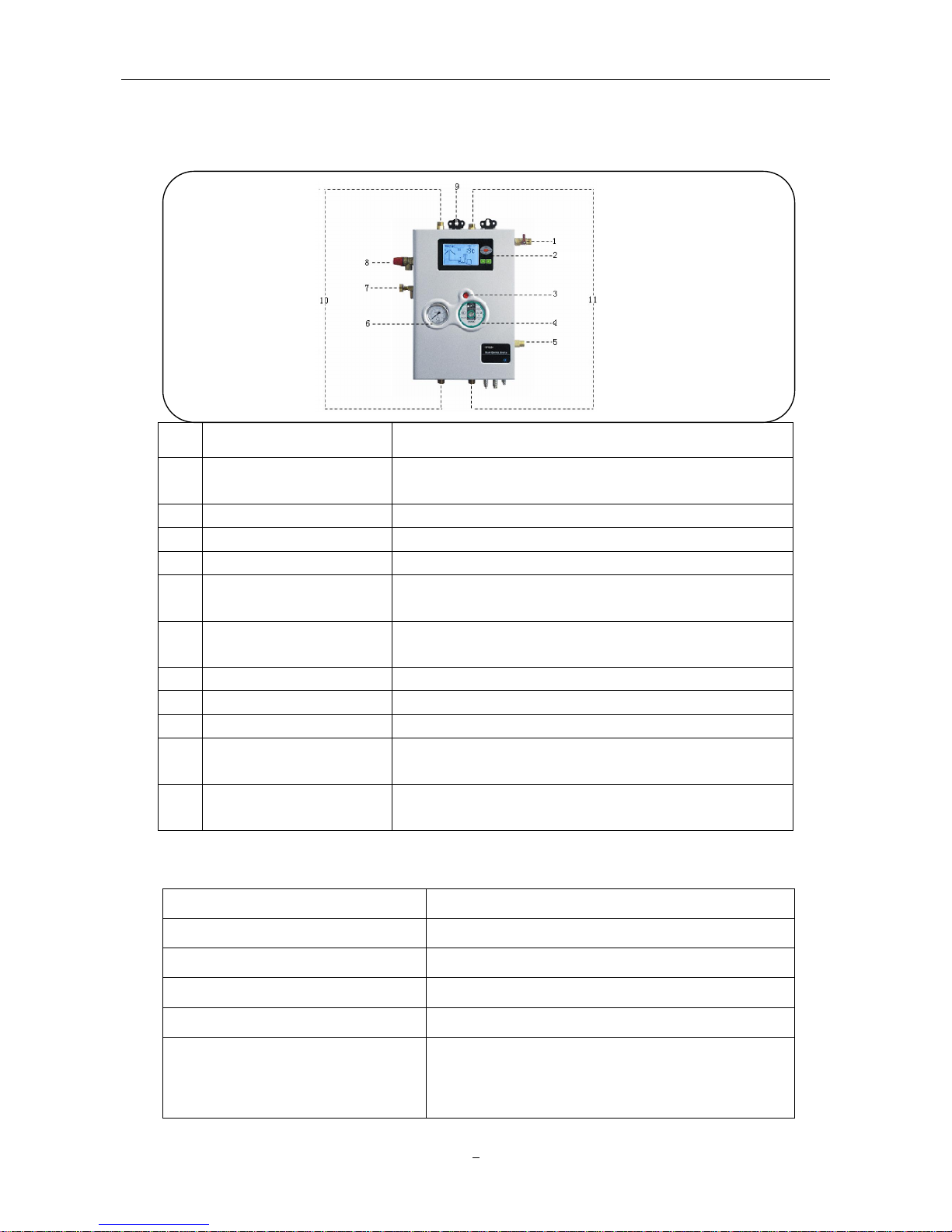
1. Components
No
Components Function description
1
Filling and flushing
connector
Through this connector medium can be pumped into
solar system
2 Operating screen (LCD) Display operating menu.
3 Pump speed regulation Three speed levels available, offers different flow rate.
4 Circulation pump WILO Star RS 15/6 (110V or 220V)
5
Expansion vessel
connector
Connect expansion vessel. Expansion vessel balances
the system pressure.
6 Manometer
Display system pressure (Max. 10 bar, normal working
pressure is approx. 2 bar)
7 Air vent valve Empty the air in the solar system
8 Security valve Protect the system against over-pressure.
9 Mounting point For fixing the solar pump station
10 Forward flow
Copper material, left side, Max. working temperature 150
℃, screw thread 1/2’ (DN15) as standard
11 Return flow
Copper material, right side. Max. working temperature
150 ℃, screw thread 1/2’ (DN15) as standard
2. Technical data
Dimension 450×310×150mm
Input voltage 200V~240V AC or 100V~120V AC
Power ≤3W
Accuracy of temperature measuring ±1℃
Range of temperature measuring
PT1000 : 0~199℃ NTC10K: 0~99℃
Input signals
2 x PT1000 sensor temperature probe ≤500℃,
silicon cable ≤280℃;
4 x NTC10K sensor temperature probe≤135℃,
PVC cable ≤105℃
Page 5
Work station series for solar water heating control system
3
Output signals
1 x Auxiliary heating output (Max. load current: 15A)
4 x Relay output (Max. load current: 3A)
System design pressure 10 bar
Safety valve response pressure 6 bar
WILO pump SR15/6
Ambient temperature -10~50℃
Water protection grade
IP40
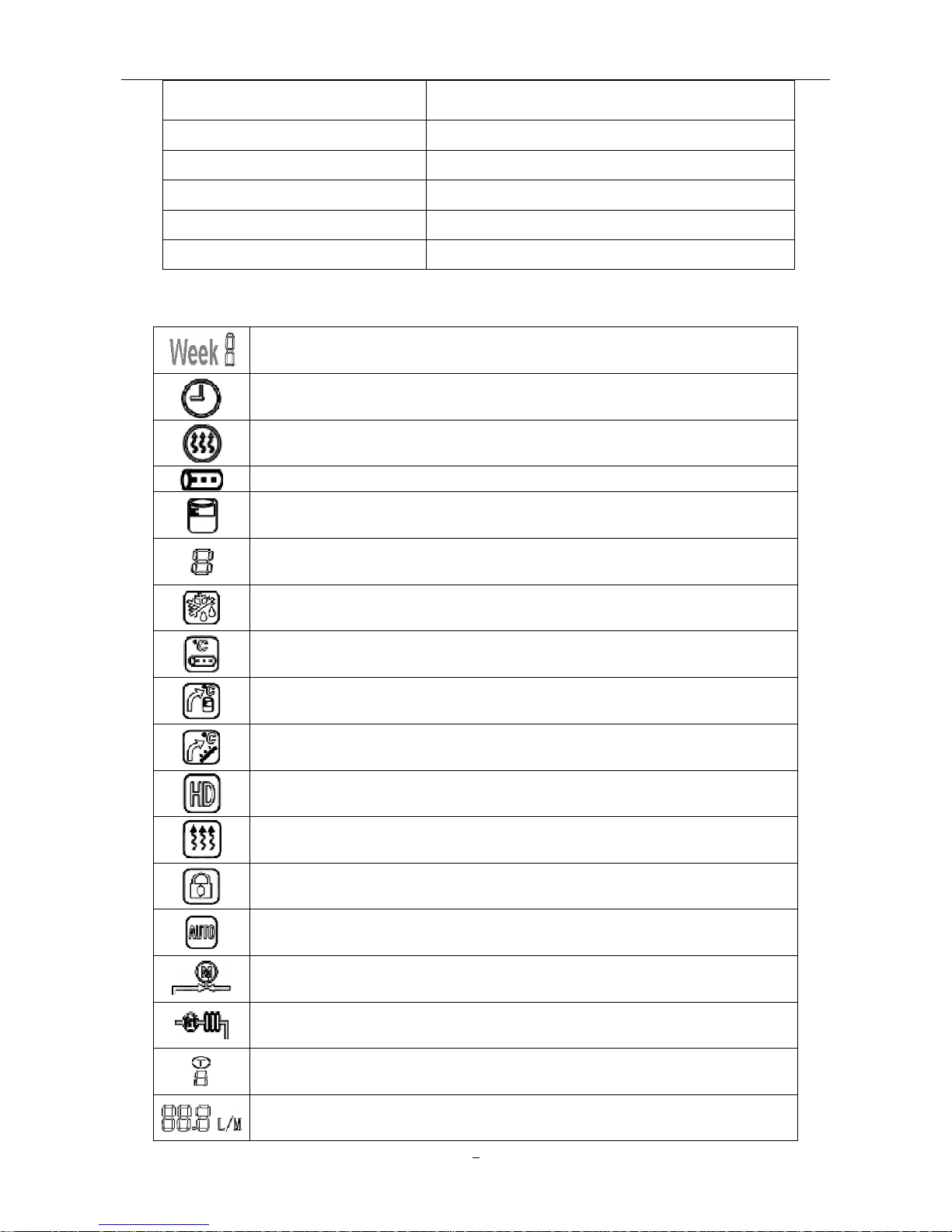
3. Display signals
Weekday: 7days of week can be set (e.g. Week 1 means “Monday”).
Time: Setting hours and minutes.
Time-controlled auxiliary heating: Setting three heating time periods.
Time-controlled hot water circulation: Setting three time periods.
Storage temperature: As turning-on/off temperature value for auxiliary heating.
Solar system indication. 8 systems are available.
Frost protection.
Temperature-controlled circulation function
Overheating protection for storage.
High temperature protection for solar collector.
Holiday function.
Switch on/off auxiliary heating manually.
Forbid/permit using auxiliary heating.
Reset.
Extended temperature-difference circulation function
Recooling the system through by-pass
Temperature display.
Flow rate display.
Page 6
Work station series for solar water heating control system
4
Ⅲ System description (8 systems available)
Danger: If there is only one temperature sensor in water storage (usually in bottom part T2),
it is possible, and that the auxiliary heating function will not be activated or deactivated at a
right time, because the water temperature in top part of the storage (T3) cannot be measured.
In this case, if you still want to use auxiliary heating function, control program will automatically
take the signal from bottom temperature sensor (T2) instead of T3. However, water in top part
of storage might often be overheated. It may cause damages to material and persons. So it is
highly recommended not to use auxiliary heating in such a case.
Note: To lock this function, please press “Choose Function” button until the signal” ”
appears
on
the screen (see details in 8 Forbid/Permit auxiliary heating).
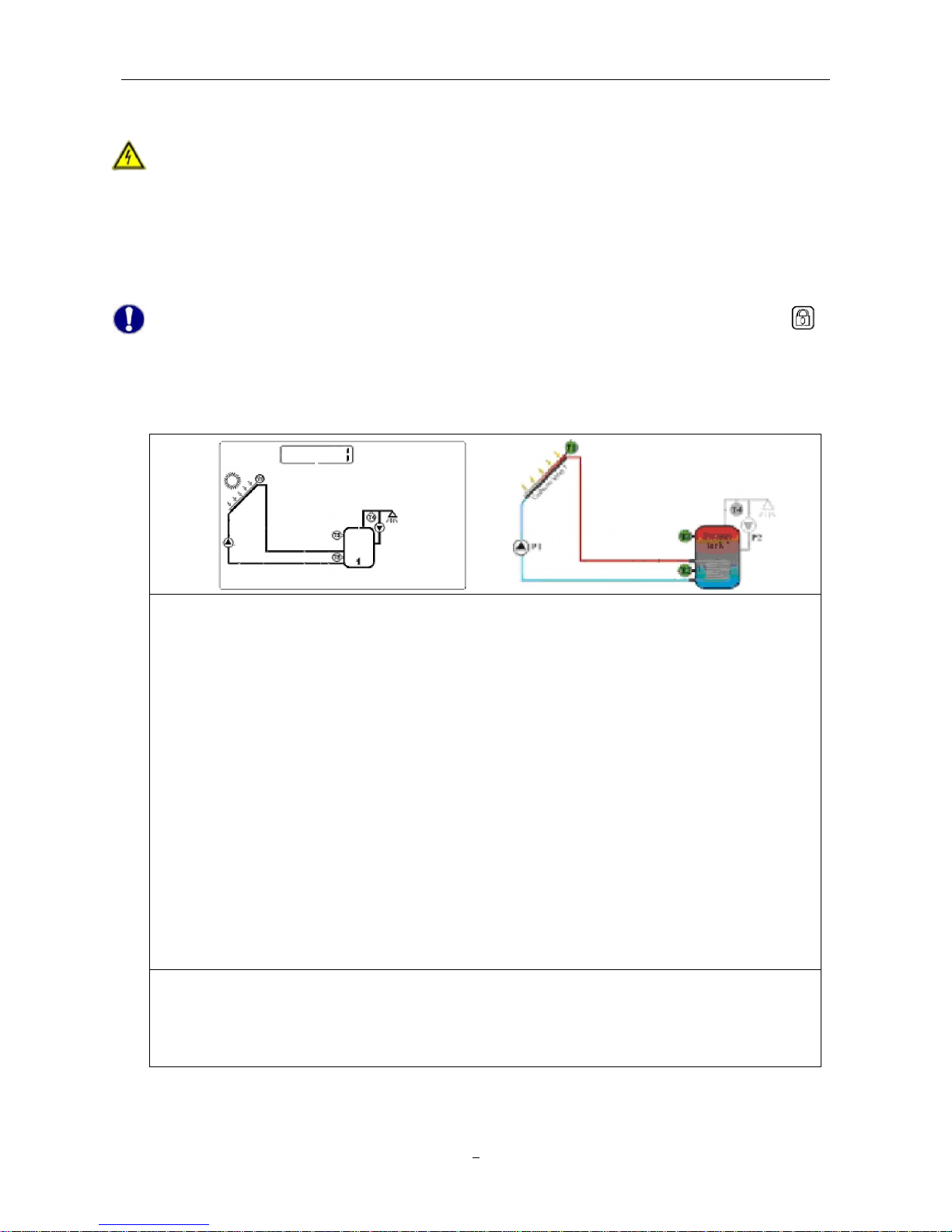
1. System 1: 1 collector array – 1 storage – 1 pump
Description:
The solar collector pump (P1) is activated as soon as the temperature difference
between the collector array (T1) and the storage (T2) is reached. When the temperature
difference between T1 and T2 drops below the switch-off temperature difference, or the
storage (T3) reaches its maximum storage temperature, the solar pump (P1) will be
switched off.
T3 is used to measure the temperature of the top part of storage. If the turning-on
condition for auxiliary heating is filled, the auxiliary heating will be activated
T1:
Temperature sensor for collector 1
T2: Temperature sensor in the bottom part of storage 1
T3: Temperature sensor in the top part of storage 1
T4: Temperature sensor for hot water pipe
P1: Solar collector pump
P2: Solar circulation pump
Note:
1. T3, T4, P2 are suitable for system 1-8.
2. T3 is alternative, when no sensor (T3) is installed in the top part of tank, control system
will use the signal of sensor T2 automatically to control the auxiliary heating.
Page 7

Work station series for solar water heating control system
5
2. System 2: 1 collector array – 2 storage – 2 pumps
Description:
When switch–on temperature difference between collector array (T1) and one of the
storage (T2 or T5) is reached, the solar circuit pump (P1) or (P0) will switched on.
According to the priority switching, two storages (T2, T5) will be loaded one by one. Until
either of switch-off temperature difference between collector array (T1) and storage (T2,
T5) is reached, or the maximum storage temperature is reached, pump stops working.
T1:
Temperature sensor for collector 1
T2: Temperature sensor in the bottom part of storage 1
T3: Temperature sensor in the top part of storage 1
T4: Temperature sensor for hot water pipe
T5: Temperature sensor in storage 2
P0: Solar collector pump
P1: Solar collector pump
Note:
The default priority storage is storage1.
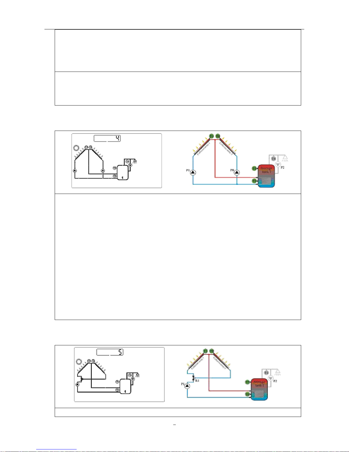
3. System 3: 1 collector array – 2 storages– 1 pump – 1 valve
Description:
When switch–on temperature difference between collector array (T1) and one of the
storage (T2 or T5) is reached, then the solar pump (P1) is switched on and valve (R1) is
set to the correct position depending on the storage to be loaded. According to the priority
switching, both storages (T2, T5) will be loaded one by one, until the relevant switch-off
temperature difference between the collector array (T1) and storage are reached.
(T2, T5) is reached or the maximum storage temperature of T2 or T5 is reached, pump
and valve stop working.
Page 8
Work station series for solar water heating control system
6
T1: Temperature sensor for collector 1
T2: Temperature sensor in the bottom part of storage 1
T5: Temperature sensor in the bottom part of storage 2
P1: Solar collector pump
R1: Electromagnetic 3-way valve
Note:
1.
When there is no power in the system, the electromagnetic valve (R1) must be set to
storage (T2).
2. The default priority storage is storage 1.
4. System 4: 2 collector arrays – 1 storage tank – 2 pumps
Description:
When switch–on temperature difference between storage (T2) and collector array (T1,
T0) is reached, then solar pump (P1) for collector array 1 (T1) or solar circuit pump (P0) for
collector array 2 (T0) is switched on, depending on where the temperature difference
occurs firstly. If the switch-on temperature difference is reached for both collector arrays
(T1, T0), then both pumps (P1, P0) are switched on. The pumps switch-off independently
for each other. When either of relevant switch-off temperature difference between one or
both collector arrays (T1, T0) and the storage (T2) falls below the threshold or the maximum
storage temperature is reached, then the corresponding circuit pump is switched off.
T0: Temperature sensor for collector 2
T1: Temperature sensor for collector 1
T2: Temperature sensor in the bottom part of storage1
P0: Solar collector pump
P1: Solar collector pump
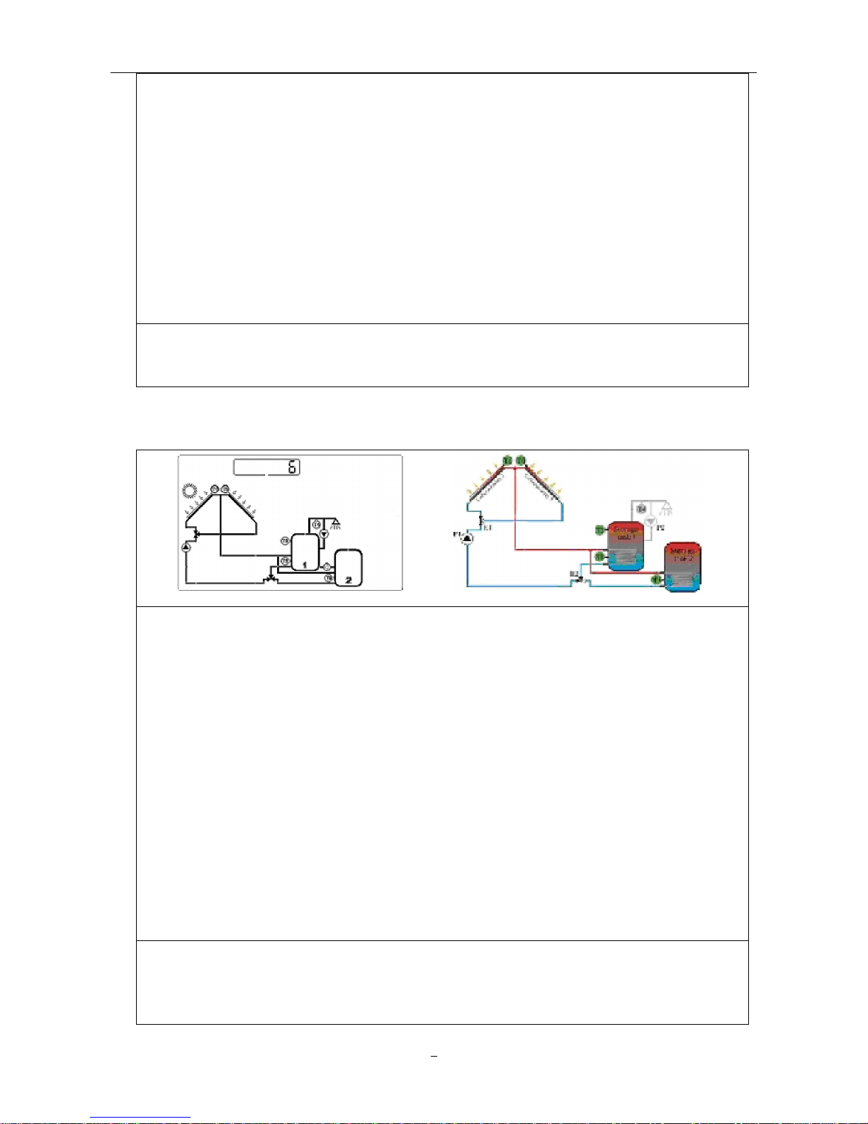
5. System 5: 2 collector arrays – 1 storage – 1 pump – 1 valve
Description:
Page 9
Work station series for solar water heating control system
7
The solar pump (P1) is switched on as soon as the switch–on temperature difference
between one of the two collector arrays (T1, T0) and storage 1 (T2) is reached, the valve
R1 is always set so that flow occurs through the warmer of the two collector arrays (T1,
T2). The pump P1 switch-off as soon as the switch-off temperature difference between
two collector arrays (T1, T0) and storage (T2) is reached or the maximum storage
temperature is reached.
T0:
Temperature sensor for collector 2
T1: Temperature sensor for collector 1
T2: Temperature sensor in the bottom part of storage 1
P1: Solar collector pump
R1: Electromagnetic 3-way valve
Note:
When there is no power in the system, the electromagnetic valve (R1) must be set to collector
array 1.
6. System 6: 2 collector arrays – 2 storages – 1 pump – 2 valves
Description:
When switch-
on temperature difference between two storage (T2, T5) and collector array
1 (T1) or collector array 2 (T0) is reached, then the solar circuit pump (P1) is switched on,
electromagnetic valve (R2) switches the relevant storage into the solar circuit, and
electromagnetic valve (R1) switches the affected collector array (T1 or T2) into the solar
circuit. Pump (P1) stops working when the switch-off temperature difference between either
or both collector arrays and its corresponding storage 1 (T2) and storage 2 (T5) falls below
the threshold or the maximum storage temperature (T2 or T5) is reached.
T0:
Temperature sensor for collector 2
T1: Temperature sensor for collector 1
T2: Temperature sensor in the bottom part of storage 1
T5: Temperature sensor in the bottom part of storage 2
P1: Solar collector pump 1
R1: Electromagnetic 3-way valve
R2: Electromagnetic 3-way valve
Note:
1. When
there is no
power in the system, the electromagnetic valve (R2) must be set to
storage 1 (T2), the electromagnetic valve (R1) must be set to collector array 1(T1).
2. Default priority tank is storage 1.
Page 10
Work station series for solar water heating control system
8
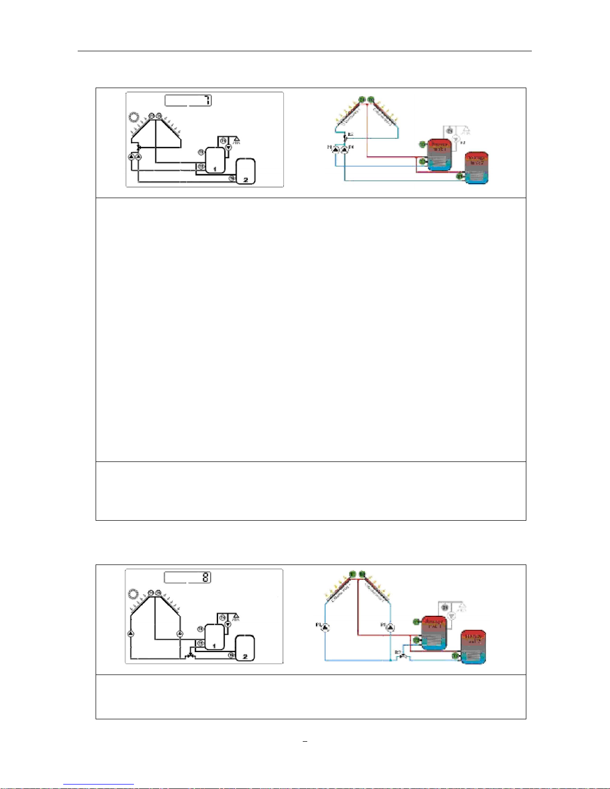
7. System 7: 2 collector arrays – 2 storages – 2 pumps – 1 valve
Description:
When switch-on temperature difference between one of the two storages (T2, T5) and
collector array 1 (T1) or collector array 2 (T0) is exceeded, then the switching valve R2
switched the corresponding collector array (T1 or T0) into the solar circuit. Depending on
which storage has reached the switch-on temperature, solar pump (P1) for storage 1 (T2)
or solar pump (P0) for storage 2 (T5) is switched on. The switching valve R2 is always set
so that flow occurs through the warmer of the two collector arrays. Both storages (T2, T5)
will be loaded one by one, according to the priority switching, until either the relevant
switch-off
temperature difference falls below the threshold, or the maximum storage
temperature (T2 or T5) is reached.
T0: Temperature sensor for collector 2
T1: Temperature sensor for collector 1
T2: Temperature sensor in the bottom part of storage 1
T5: Temperature sensor in the bottom part of storage 2
P0: Solar collector pump
P1: Solar collector pump
R2: Electromagnetic 3-way valve
Note:
1. When
there is no
power in the system, the electromagnetic valve (R2) must be set to
collector array 1(T1).
2. Default priority storage is storage 1.
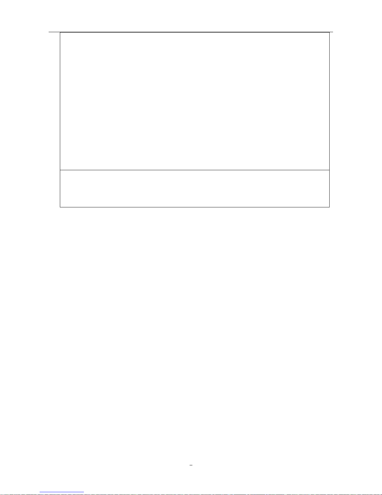
8. System 8: 2 collector arrays – 2 storages – 2 pumps – 1 valve
Description:
When switch-on temperature difference between one of the two storage (T2, T5) and
collector array1 (T1) and collector array2 (T0) is reached, then the switching valve (R2)
Page 11
Work station series for solar water heating control system
9
switches relevant storage (T2, or T5) to the solar circuit. Then either solar circuit pump P1 for
collector array 1 (T1) or solar circuit pump P0 for collector array 2 (T0) is switch-on,
Depending on where the temperature difference occurs. If the switch-on temperature
difference is reached between collector arrays (T1, T0), then both pumps (P1, P0) are
switch-on. Pump (P1, P0) switch-off independently of each other, when both of relevant
switch-off temperature difference between collector arrays (T1, T0) and relevant storage (T2
or T5) falls below the threshold, or the maximum storage temperature is reached.
T0: Temperature sensor for collector 2
T1: Temperature sensor for collector 1
T2: Temperature sensor in the bottom part of storage 1
T5: Temperature sensor in the bottom part of storage 2
P0: Solar collector pimp 2
P1: Solar collector pump 1
R2: Electromagnetic 3-way valve
Note:
1. When no power is in the system, the electromagnetic valve (R2) must be set to storage 1
(T1).
2. Default priority storage is storage 1.
Page 12
Work station series for solar water heating control system
10
Ⅳ Functions and operation
Danger: Before connecting the power supply, make sure that the storage, solar collector, solar
work station and all temperature sensors are good connected!
Note: For safety, auxiliary heating is locked at delivery state. The single “
” displays on the
screen. If you want to use this function, please see operation: 8. Forbid/Permit using auxiliary
heating.
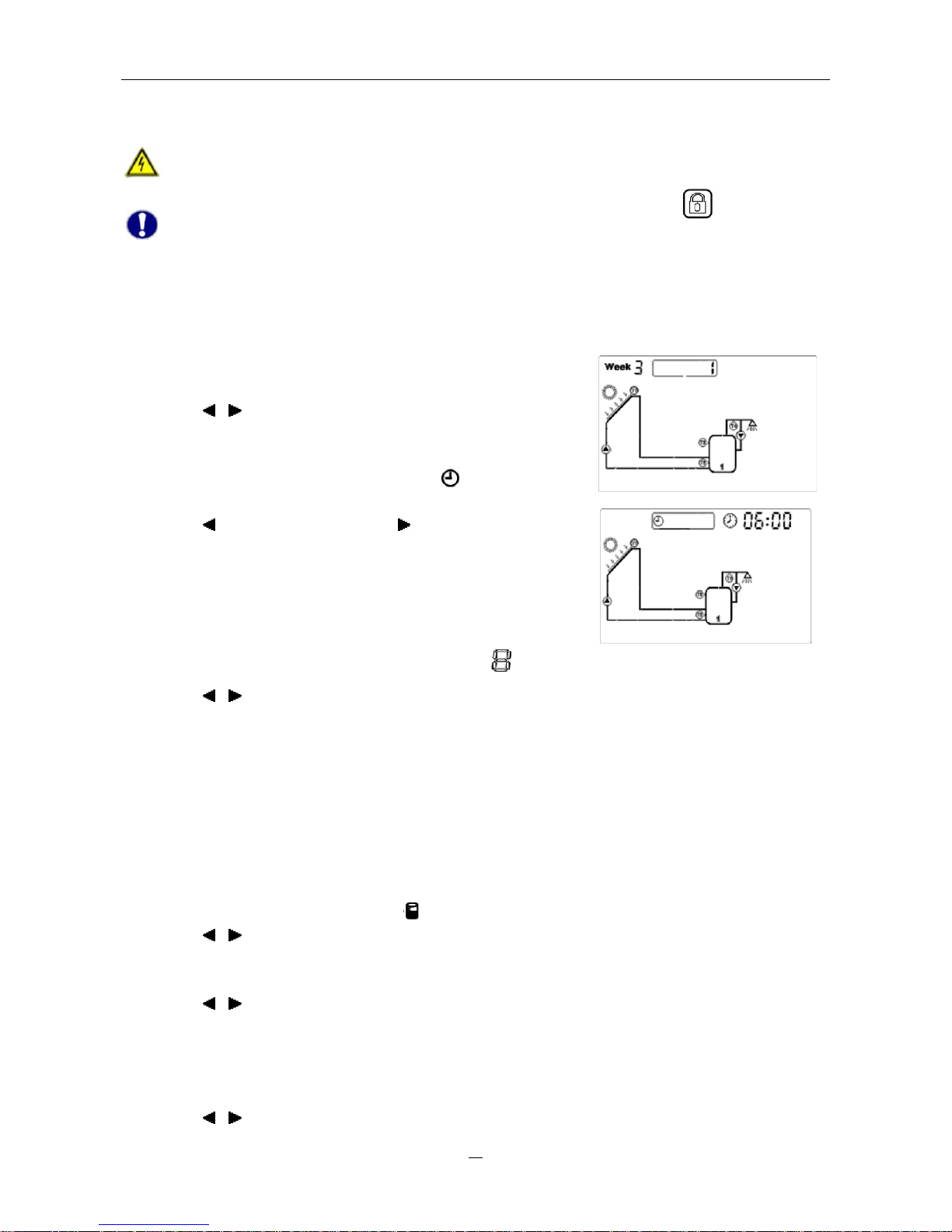
1. Setting week and time
After power supply is switched on, please firstly set the time of the system.
ì Press “System Setting” button until the signal “Week” display
on the screen.
ì Press “
” “ ” button to set weekday.
ì Press “Confirm” button to save the setting; press “Cancel”
button to cancel the setting.
ì Press “System Setting” button again until “
” displays on
the screen.
ì Press “ ” button to set hour, press “ ” button to set minute.
ì Press “Confirm” button to save the setting; press “Cancel”
button to cancel the setting.
2. Selecting a system
ì Press “System Setting” button until the signal “ ” displays on the screen.
ì Press “
” “ ” button to select a system.
ì Press “Confirm” button to confirm the setting.
ì Press “Cancel” button to cancel the setting.
3. Temperature difference circulation function
The solar control program works on the principle of temperature difference circulation. Solar
pump P1 is triggered, as soon as the preset temperature difference between collector and
storage is reached. If there is more than one storage or one collector array, system will compare
the temperature difference between collectors and storage automatically.
ì Press “System Setting” button, until “ ” displays on the screen.
ì Press “ ” “ ” button to adjust storage temperature. Default value: 60℃, setting range: 45~75℃.
ì Press “Confirm” button to save the setting. Press “Cancel” button to cancel this function.
ì At the same time the menu shows “10℃”, the default value of switch-on temperature difference.
ì Press “
” “ ” button to adjust it. Setting range: 5~20℃.
ì Press “Confirm” button to save the setting. Press “Cancel”
button to cancel this function.
ì Then the menu shows “5℃”, the default value of switch-off
temperature difference.
ì Press “
” “ ” button to adjust it, adjustable range: 2~12℃.
Page 13
Work station series for solar water heating control system
11
ì Press “Confirm” button to confirm the setting. Press “Cancel” button to cancel the function.
Note: Between 60~70℃ scale can form more easily; we usually set the storage temperature at
60℃.
4. Time-controlled auxiliary heating
Solar thermal system can be combined with electric boiler or gas/oil boiler. The system is supported
with a default program which can be customized to meet your individual needs. You can create a
timer program with up to three time periods to heat the water to a desired value. During the three
preset time periods, auxiliary heating starts working, when the water temperature in top part of
storage (T3) is below preset turning-on temperature, and it stops working, when T3 exceeds the
required temperature.
Note: Default setting: the first time period: 04:00 turning-on, 05:00 turning-off; the second time
period: 10:00~10:00; the third time period: 17:00
turning-on, 22:00 turning-off.
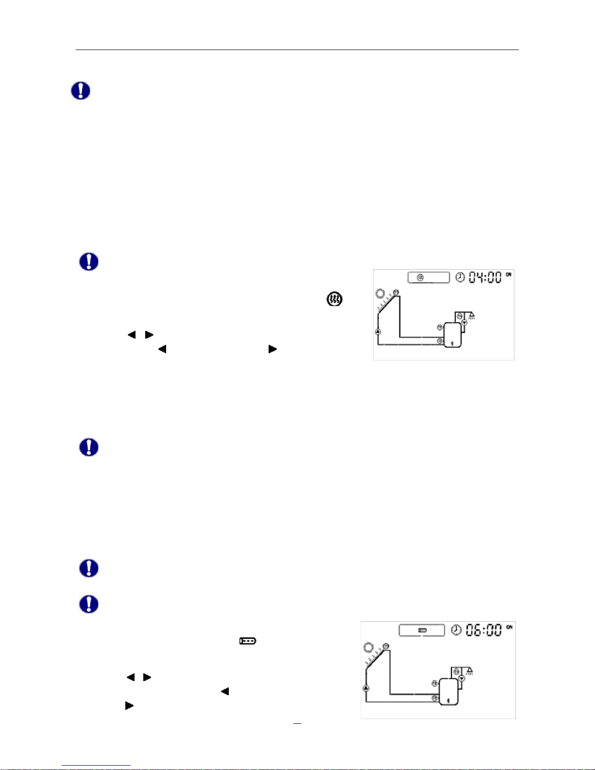
ì Press “System Setting” button until the signal “
”
appears.
ì Press “ ” “ ” button to set the start time of the first time
period. Press “ ” to adjust hours, press “ ” button to adjust
minutes.
ì Press “Confirm” button to save the settings, press “Cancel” button to cancel the settings.
ì Immediately after setting the first time period, the display enters into the operating menu of next time
period.
ì Perform like above steps, the other two time periods can be set.
Note: If you want to shut off one of the three time periods, you can set a same value for both
start time and ending time, e.g., you can set both the start and ending time of second time period
at 10:00 am.
5. Time-controlled circulation function
This function needs an extra circulation pump (P2). You can set up a timer program with up to three
time periods. This pump can be triggered at times when hot water will be needed.
Note: Within the preset three time periods, pump P2 always stops for 15 minutes after operating
for 3 minutes.
Note: Default setting: the first time period: 06:00 turning-on, 08:00 turning-off; the second time
period: 10:00~10:00; the third time period: 19:00 turning-on, 21:00 turning-off. Three time
periods should be set within one day (24 hours).
ì Press “System Setting”, until “ ” displays on the
screen.
ì Press “ ” “ ” button to adjust the start time and end time
of first time period. Press “ ” button to adjust hours,
press “
” button to adjust minutes.
Page 14
Work station series for solar water heating control system
12
ì Press “Confirm” button to confirm the setting, press “Cancel” button to cancel this setting.
ì Immediately after setting the first time period, the display enters into the operating menu of next time
period.
ì Perform like above steps, the other two time periods can be set.
Note: If you want to shut off one of the three time periods, you can set a same value for both
start time and ending time, e.g., you can set both the start and ending time of second time period
at 10:00 am.
6. Temperature-controlled circulation function
Solar system provides temperature-controlled hot water circulation function. This function needs an
extra hot water circulation pump (P2) and a sensor (T4). When the temperature of T4 falls below the
preset temperature value, the circulation pump (P2) starts operating, until the temperature exceeds
the preset temperature.
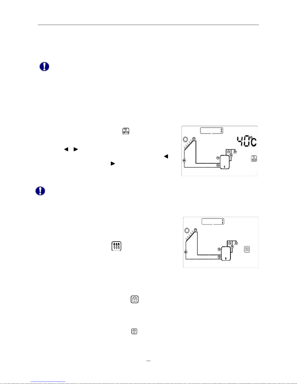
ì Press “Choose Function”, until “
” displays on the
screen.
ì Press “ ” “ ” button to adjust the temperature value,
default value: 40℃, setting range: 20~50℃. Press “ ”
button to adjust hours, press “ ” button to adjust minutes.
ì Press “Confirm” button to confirm the setting, press
“Cancel” button to cancel this setting.
Note: In order to avoid measuring error, the position of sensor T4 should be minimum 1.5m far
from the storage.
7. Switching on/off auxiliary heating manually
If you want to use warm water immediately, but the water
temperature doesn’t reach the desired value, you can switch
on/off the auxiliary heating manually.
ì Press “confirm” button, until “ ” displays on the screen
to switch on auxiliary heating manually.
ì Press “Cancel” button to switch off auxiliary heating
manually.
8. Forbid/Permit using auxiliary heating
ì Press “Choose Function” button, until “ ” displays on the
screen.
ì Press “Confirm” button to save the setting and forbid
auxiliary heating.
ì Press “Choose Function” button until “ ” displays on the
screen.
ì Press “Cancel” button to cancel the setting and permit
auxiliary heating.
Page 15
Work station series for solar water heating control system
13
Note: When forbid auxiliary heating, customer can’t switch on/off auxiliary heating manually and
time-controlled auxiliary heating function is also automatically deactivated.
9. Frost protection
In winter, when the temperature of collector drops below the preprogrammed starting temperature of
frost protection (default value 5℃), solar pump P1 starts working. When collector temperature
exceeds the switch-off temperature of frost protection, pump P1 stops working and the system exits
frost protection.
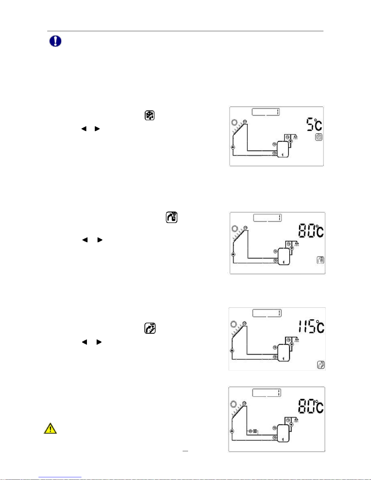
ì Press “Choose Function”, until “
” displays on the screen.
ì Press “ ” “ ” button to adjust the temperature of frost
protection. Setting range: 3℃–10℃.
ì Press “Confirm” button to confirm the setting, press “Cancel”
button to deactivate this function.
10. Storage overheating protection
To avoid overheating of water storage, system is supported with an overheating protection function.
When the temperature of storage (T3) is higher than the maximum temperature, even the condition of
temperature difference circulation is reached, solar pump is still forbidden to operate.
ì Press “Choose Function” button, until
displays on the
screen.
ì Press “
” “ ” button to adjust the maximum storage
temperature. Default value: 80℃, setting range: 60–90℃.
ì Press “Confirm” button to confirm the setting, press “Cancel”
button to quit the function.
11. High temperature protection of solar system
When collector temperature reaches 115℃, and meanwhile the storage doesn’t reach the max.
temperature, the high temperature protection function of solar
system will be activated.
ì Press “Choose Function”, until
displays on the screen.
ì Press “ ” “ ” button to adjust the maximum collector
temperature. Default value: 115℃, setting range: 100–130℃.
ì Press “Confirm” button to confirm the setting, press “Cancel”
button to quit this function.
12. Recooling the system by through by –pass
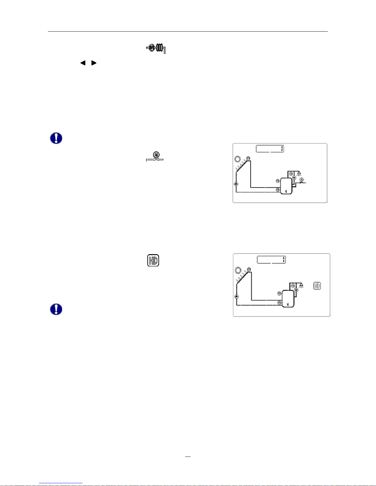
This function can realize recooling the solar system through an
extra installed radiator (by-pass).
Attention: The by-pass is controlled by corresponding
electromagnetic 3-way valve R2, but the operation menu
Page 16
Work station series for solar water heating control system
14
shows R1, it’s an error indication!
ì Press “Choose Function”, until “
”
displays on the screen.
ì Press “ ” “ ” button to adjust the switch-on temperature (T1). Default value: 80℃, setting range:
60~90℃.
ì Press “Confirm” button to confirm the setting, press “Cancel” button to quit this function.
13. Extended temperature-difference circulation function
The Following described function can extend a simple “1 collector array-1 storage” solar system with
an additional temperature difference circulation.
Note: Only if the input T0, T5 and output R2 are not occupied, this function can be activated.
ì Press “Choose Function”, until “
” displays on the screen.
ì Press “Confirm” button to activate this function. Press “Cancel”
button to quit this function.
14. Holiday function
If you intend to be absent for an extended period (holiday), or hot water is not required for an
extended period, you can activate the holiday function. This function is activated nightly(22:00-06:
00)to re-cool the storage and to prevent high thermal loads of the solar system due to completely
heated storage.
ì Press “Choose Function”, until “
” displays on the screen, it
indicates that the function is active.
ì Press “Confirm” button to confirm this setting. Press “Cancel”
button to deactivate this function.
Note: When using holiday function, system will lock
auxiliary heating automatically.
15. Anti-bacteria protection
To safeguard the water hygiene, solar system will monitor the storage temperature. If the
temperature never reaches 70℃ in every 7 days, auxiliary heating will be activated automatically and
heats the storage temperate to 70℃.
16. Collector emergency cut-off
When the temperature of collector reaches or exceeds 120℃, in order to prevent evaporation of heat
medium liquid and protect other components of solar system, solar circulation pump will be stopped
compulsively, until the temperature of collector gets lower.
17. Memory function
In case of power failure, solar control system is able to remain the preset parameters unchanged.
Page 17
Work station series for solar water heating control system
15
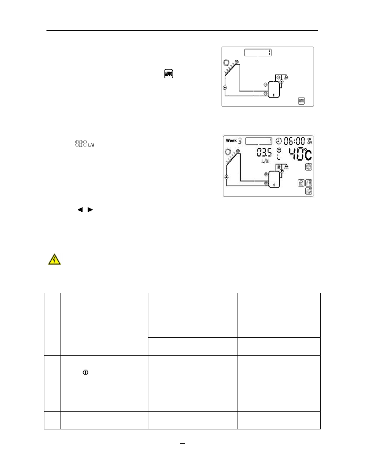
18. Reset Function
If necessary, all the settings (except time setting) can be reset
to the factory settings.
ì Press “Choose Function” button, until “ ” displays on the
screen.
ì Press “Confirm” button, all of parameters will be reset to
factory settings.
19. Manual operations
Customers can monitor the flow rate anytime by viewing the
signal “
” on main operating menu. And when there are
no other operations and it returns to main menu, they can also
activate some functions by pressing different buttons directly.
ì Press “Confirm” button to switch on/off solar collector pump
(P1) manually.
ì Press “Cancel” button to switch on/off solar hot water
circulation pump (P2) manually.
ì Press “
” “ ” button repeatedly to check the temperature values in different part of solar system.
Ⅴ Fault messages
Danger: Never try to repair the solar pumping station yourself! Consult a specialist in case of an
error.
The following table explains the error messages and corresponding handling indication. Most of the
problems can be found in the list below.
No.
Familiar problem Possible reason Solution
1
Pump works but no flow rate
displays.
There is probably too much air
in the pipeline.
Replenish heat medium liquid
and exhaust the air.
Storage reaches max. temp.
When storage temperature
drops, pump starts working.
2
System has temp. difference
but pump doesn’t work.
Solar collector reaches its max.
temp..
When collector temperature
drops, pump starts working.
3
Pump doesn’t work, and the
signal “ ” blinks.
There is probable broken circuit
or short circuit with temperature
sensors.
Check the sensor wiring and
replace sensors if necessary.
Auxiliary heating is forbidden. Activate it manually.
4 Auxiliary heating doesn’t work.
Temperature sensor has broken
circuit or short circuit.
Check sensor connection and
make the wiring again.
5
Auxiliary heating still operates
at 23:00.
Anti-bacteria function starts up. It’s normal.
Page 18
Work station series for solar water heating control system
16
6 System pressure drops.
There is air leakage in solar
system.
Check the pipeline and
exhaust the air.
Frost function is activated.
7
Pump works but system
doesn’t have temp. difference,
Holiday function is activated.
No error.
The solar work station SP118 shows error messages in the main operating menu if there is a problem
with temperature sensor.
Error
message
meaning Possible cause Error rectification
<FF℃>
There is broken circuit
with sensor connections.
Sensor wiring interrupted, not
connected or short circuit.
Check resistance value,
replace sensor if necessary.
<FE℃>
There is a short circuit
with sensor connections.
Sensor wiring interrupted, not
connected or short circuit.
Check resistance value,
replace sensor if necessary.
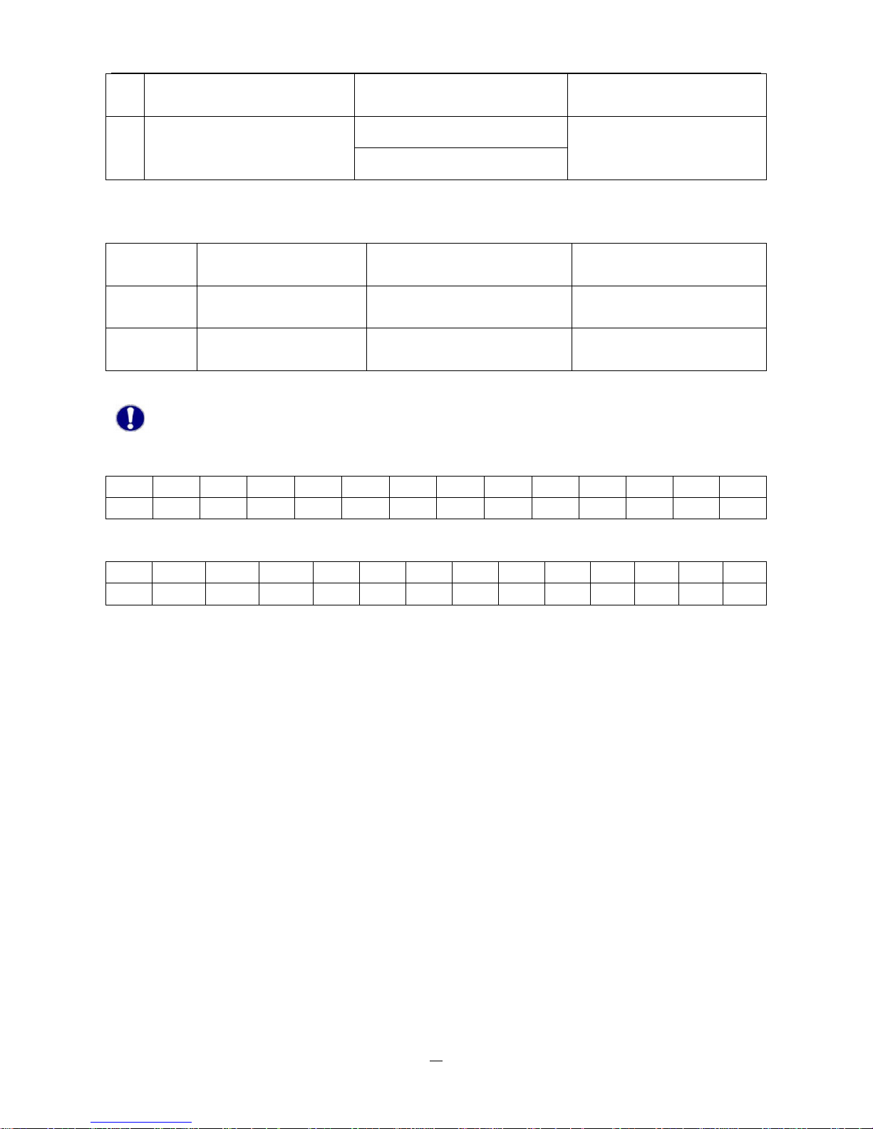
Note: A potentially defective sensor can be checked using an ohmmeter. To do this, the sensor
must be disconnected. Its resistance value can be compared with the figures below, small
deviation is acceptable.
PT1000 resistance value
℃ 0 10 20 30 40 50 60 70 80 90 100 110 120
Ω 1000 1039 1077 1116 1155 1194 1232 1270 1309 1347 1385 1422 1460
NTC 10K B=3950 resistance value
℃ 0 10 20 30 40 50 60 70 80 90 100 110 120
Ω 33620 20174 12535 8037 5301 3588 2486 1759 1270 933 697 529 407
Page 19
Work station series for solar water heating control system
17
Part 2: Installation instruction
Ⅰ
General information
1. Safety
Before installing the device, please read this
manual
carefully. Please note that the installation
must be executed according
to relevant technical rules.
The installation must be adapted to the
conditions provided by the customer. Damages by improper using or incorrect modification of
installation and construction
are on
costumer site.
Attention: This manual is for trained personals only!
Note: As faults can never be excluded, we don’t offer a guarantee for the completeness of the
drawings and texts of this manual, they only represent some examples.
2.
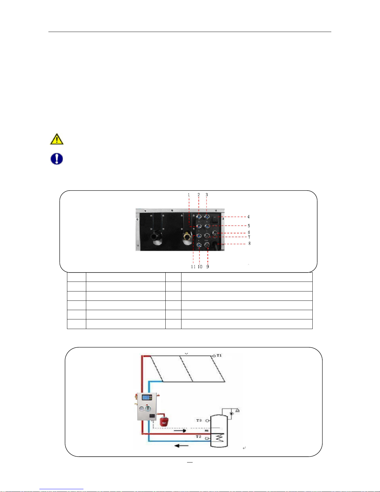
Input and output signals
1 T3 connector 7 P0 pump or R1 electromagnetic 3-way valve
2 T2 connector 8 Power cord and auxiliary heating connection
3 T0 connector 9 R2 electromagnetic 3-way valve
4 Power switch 10 T5 connector
5 T1 connector 11 T4 connector
6 P2 pump
3.
System demonstration
Page 20
Work station series for solar water heating control system
18
ⅡMounting
1.
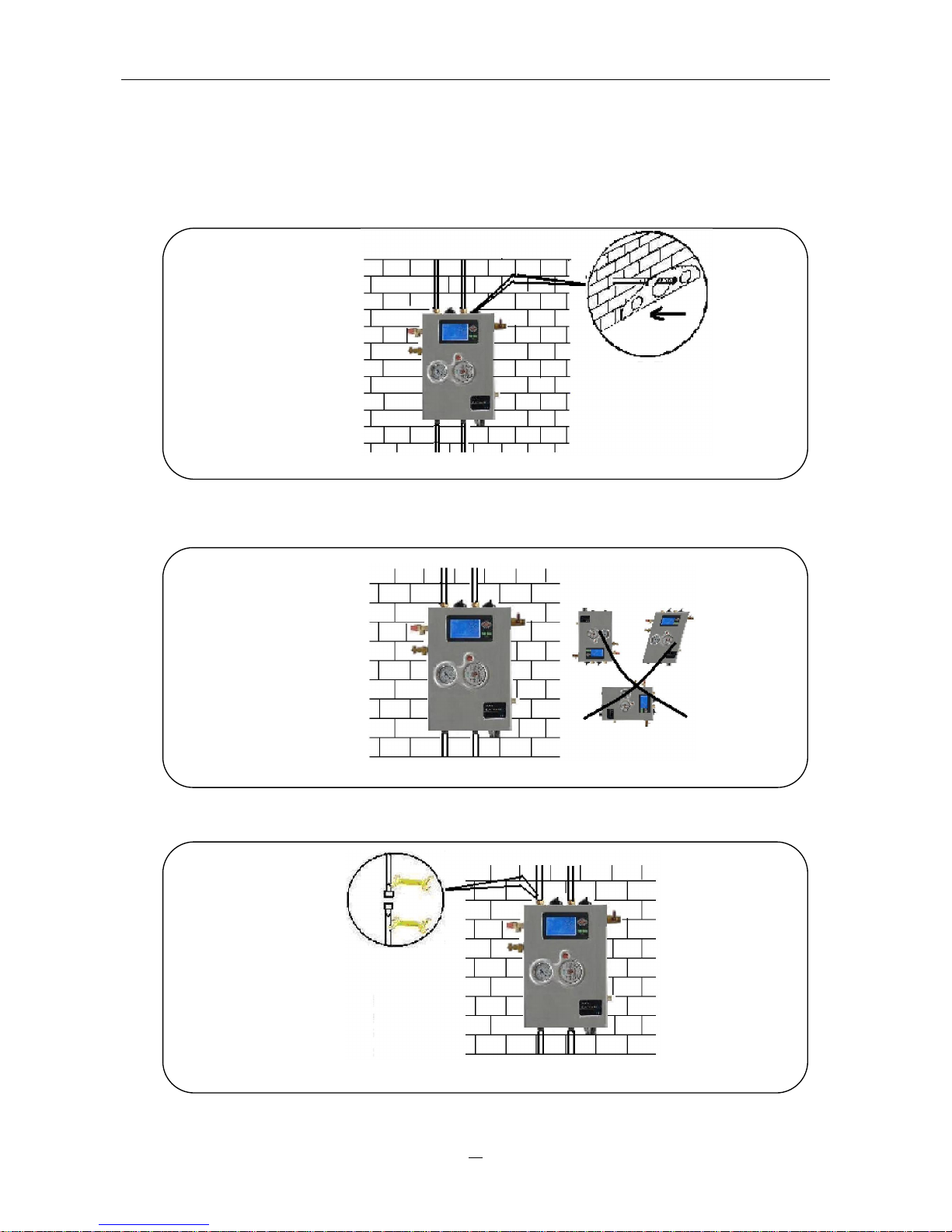
Open the package carton and take out the solar control system carefully.
Determine the mounting position of the solar control system, considering the mounting place for
expansion vessel. See picture 1.
Picture 1
2.Drill the holes for dowels, put the dowels into the holes, fixed the solar control system on the
wall using fastening screws. The solar control system must be vertically installed. See picture 2.
Picture 2
3.
Use two wrenches to connect the pipes. See picture 3.
Picture 3
Page 21
Work station series for solar water heating control system
19
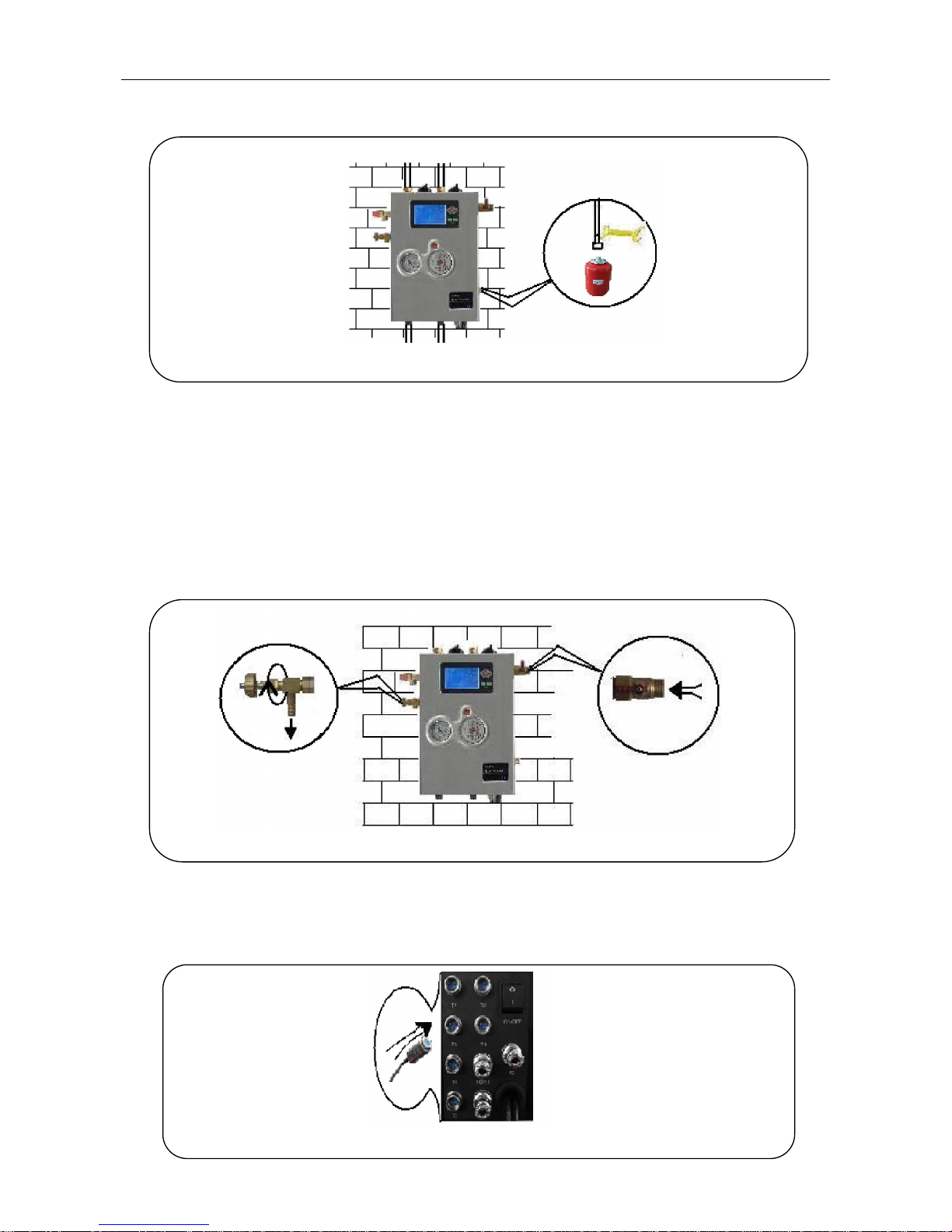
4.
Determine the mounting place for the expansion vessel. Connect the expansion vessel. See
picture5.
Picture 5
5. Filling the system
◆ Open the air vent valve.
◆ Open the filling connector (1) and connect a separate pump to the system with pressure hose.
The heat medium liquid (usually use water-glycol mixture as heat medium, 50% glycol and 50%
water) will be pumped into the system until it overflows through the air vent valve.
◆ Close the air vent valve and continue to fill the system with medium liquid until the system
pressure is not lower than 2 bar (the system pressure can be read from the manometer).
◆ Close the filling connector and switch off the pump.
Picture 6
Ⅲ Electrical wiring
1. Insert the temperature sensors into storage and solar collector. Connect these sensors to the work
station correspondingly. See picture 7.
Picture 7
Page 22
Work station series for solar water heating control system
20
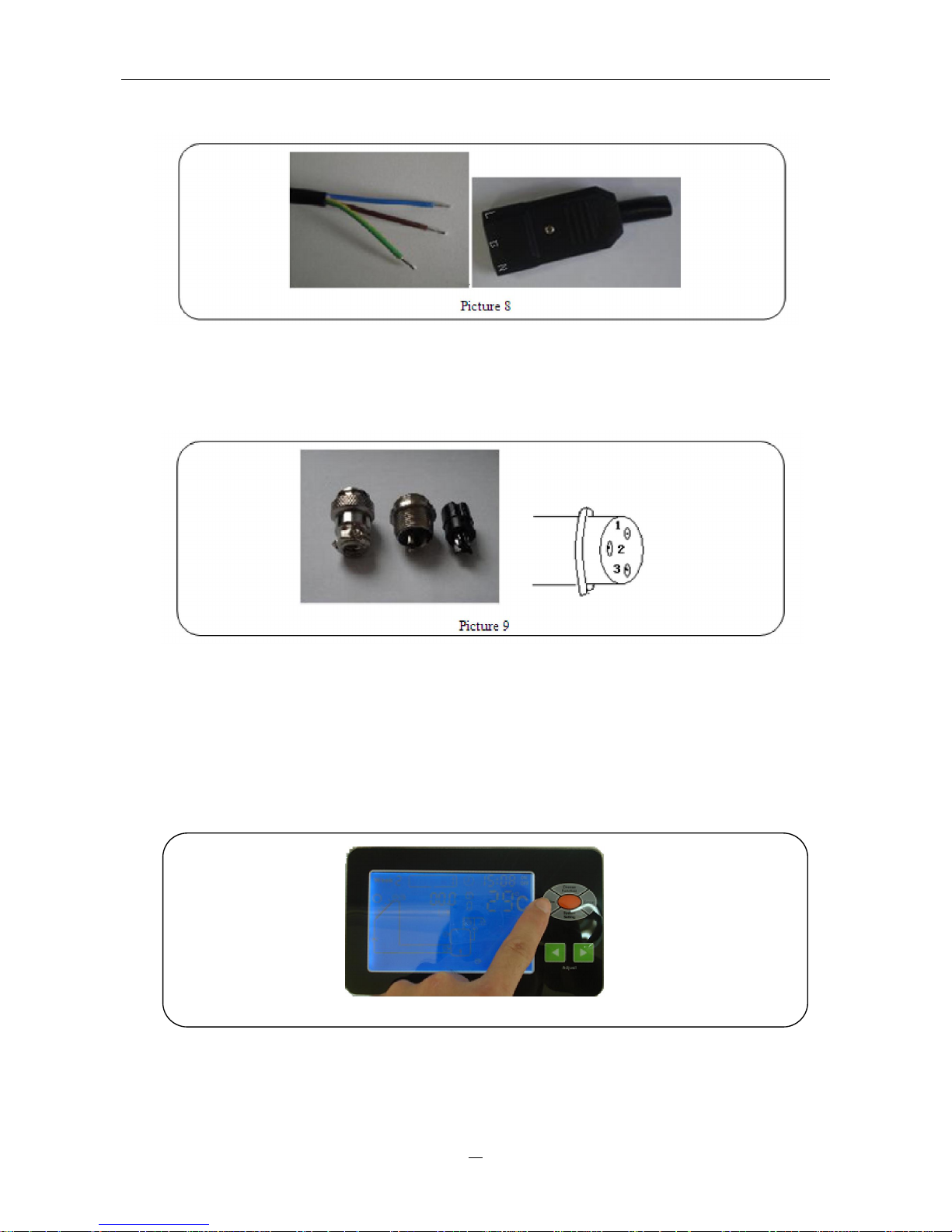
2. Connect auxiliary heating wire if available. Cable (coffee) for the “L”, cable (blue) for “N” line, cable
(yellow-green) for the ground wire.
3. To connect external circulation pumps or any electromagnetic valves, firstly loose the aviation
socket and dismount it as indicated below. Connect the wire to aviation socket, number 1
connects “N” wire, number 2 connects ground wire, number 3 connects “L” wire. Reassemble the
aviation socket and connect it to the solar control system.
4.
Tighten all joints and screw connections. Then plug the power supply into a socket.
Ⅳ
Commissioning
1.
Switch on the power of solar control system. Press “Confirm” button (in main operating menu) to
activate the solar collector pump (P1) manually and let the system circulate for a moment. See
picture 10.
Picture 10
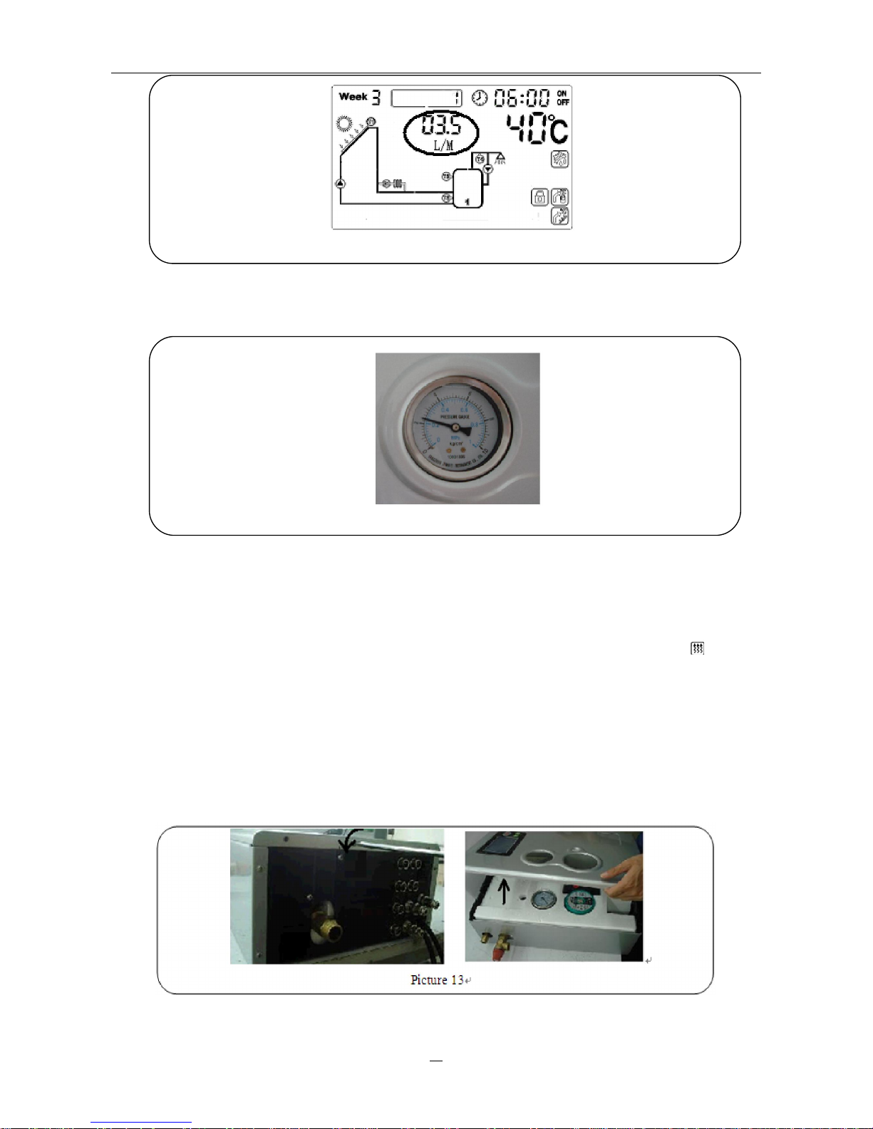
2.
Observe the flow rate of solar control system which displays on LCD screen. If the flow rate is
not regular, it indicates that there must be air still in the system. Open the air vent valve several
times to relief the air.
Page 23
Work station series for solar water heating control system
21
Picture 11
3. When the flow rate becomes regular, observe the system pressure from manometer. If the
pressure is lower than 2 bars, refill the system with heat medium to increase the pressure.
Picture 12
4.
Carry out a pressure test of all system joints again for leaks. The solar system must be vented
several times after some operating hours. Refill the system if necessary.
5. Refill the system if necessary.
6.
Remove the separate pump for filling after commissioning.
7. If
there is auxiliary heating wire connected, press “Choose Function” button until “ ” signal
displays on screen. It means switch on auxiliary heating manually. Then customer can use
auxiliary heating function.
Ⅴ
Replace the pump
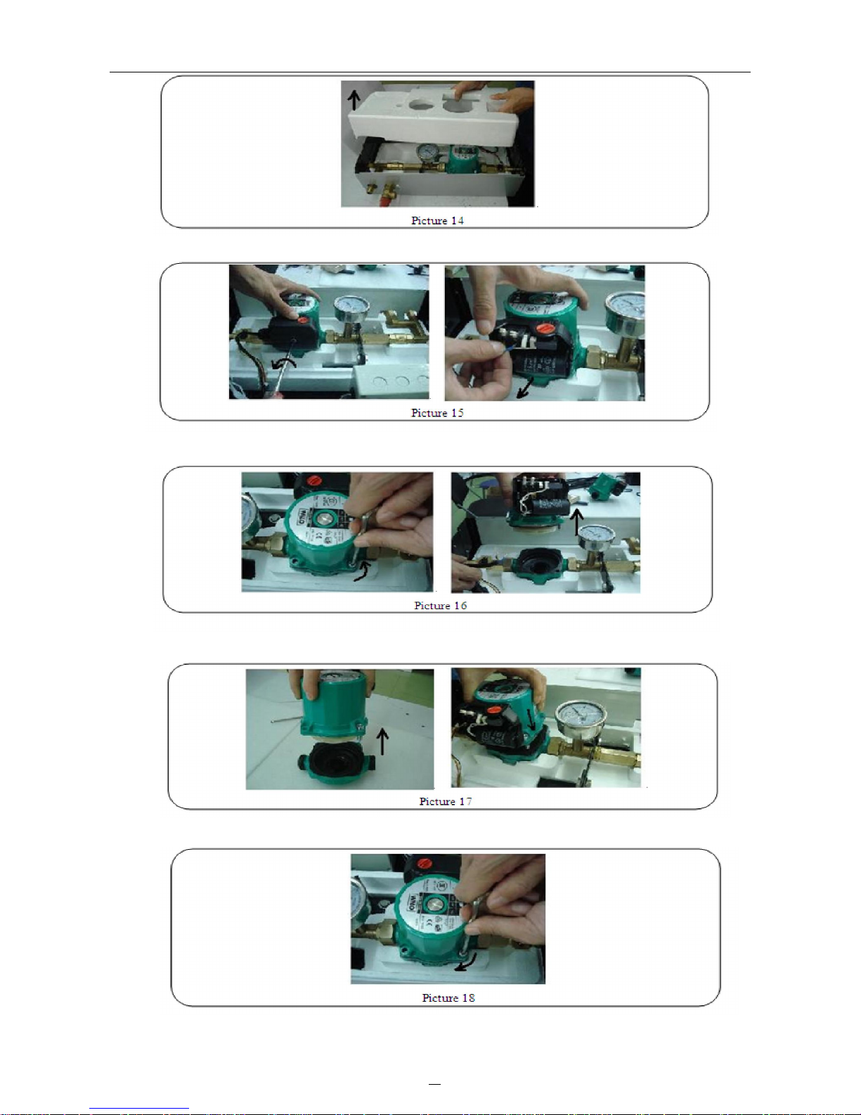
1. The integrated solar collector pump could be replaced if it gets broken. Disconnect the power
supply of solar control system. Loose the screw and open the metal cover.
2.
Remove the front half of the insulation material from system
Page 24
22
Work station series for solar water heating control system
3.
Open the terminal box,
and
disconnect the power supply connection.
4.
Loose the screws and open the WILO pump.
5. Replace the old one with a new WILO pump.
6. Fasten the WILO pump screws.
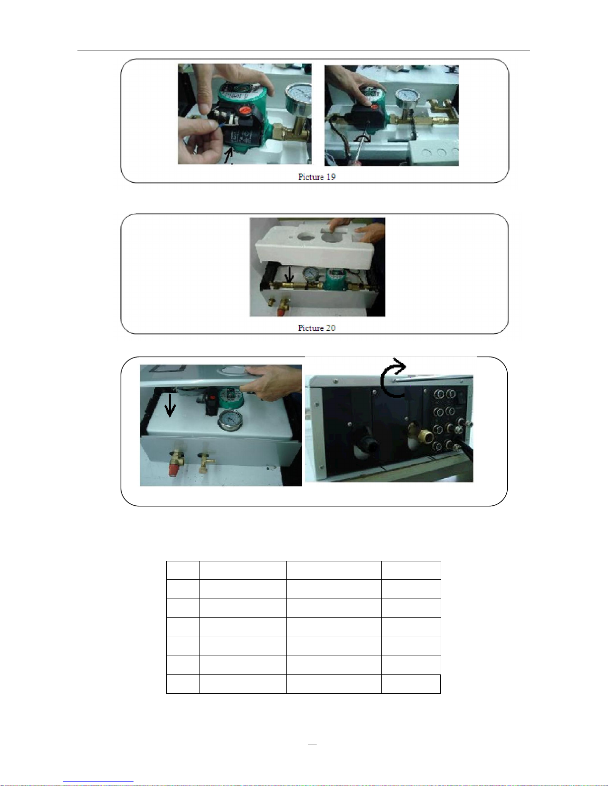
7. Connect the power supply again and close the terminal box.
Page 25
23
Work station series for solar water heating control system
8. Attach the front half the foam cover.
9. Attach the meal cover and fasten the screws again.
Picture 21
Ⅵ Packing list
No. Item Specification Quantity
1 Work station 450×310×150mm 1 pc
2 Power line 1 pc
3 PT1000 sensor 15m 2 pcs
4 NTC sensor 3m 4 pcs
5 Fixed screw 1 bag
6 Manual 1 pc
 Loading...