

Page 1
TRIO™ MP-245A
Three-Axis Motorized
Micromanipulator System
Operation Manual
With Synthetic Fourth “D” Axis and
USB Interface for External Control
Rev. 3.12b (20191001)
One Digital Drive
Voice: 415-883-0128 Web: www.sutter.com
Fax: 415-883-0572 Email: info@sutter.com
Novato, CA 94949
Page 2

2
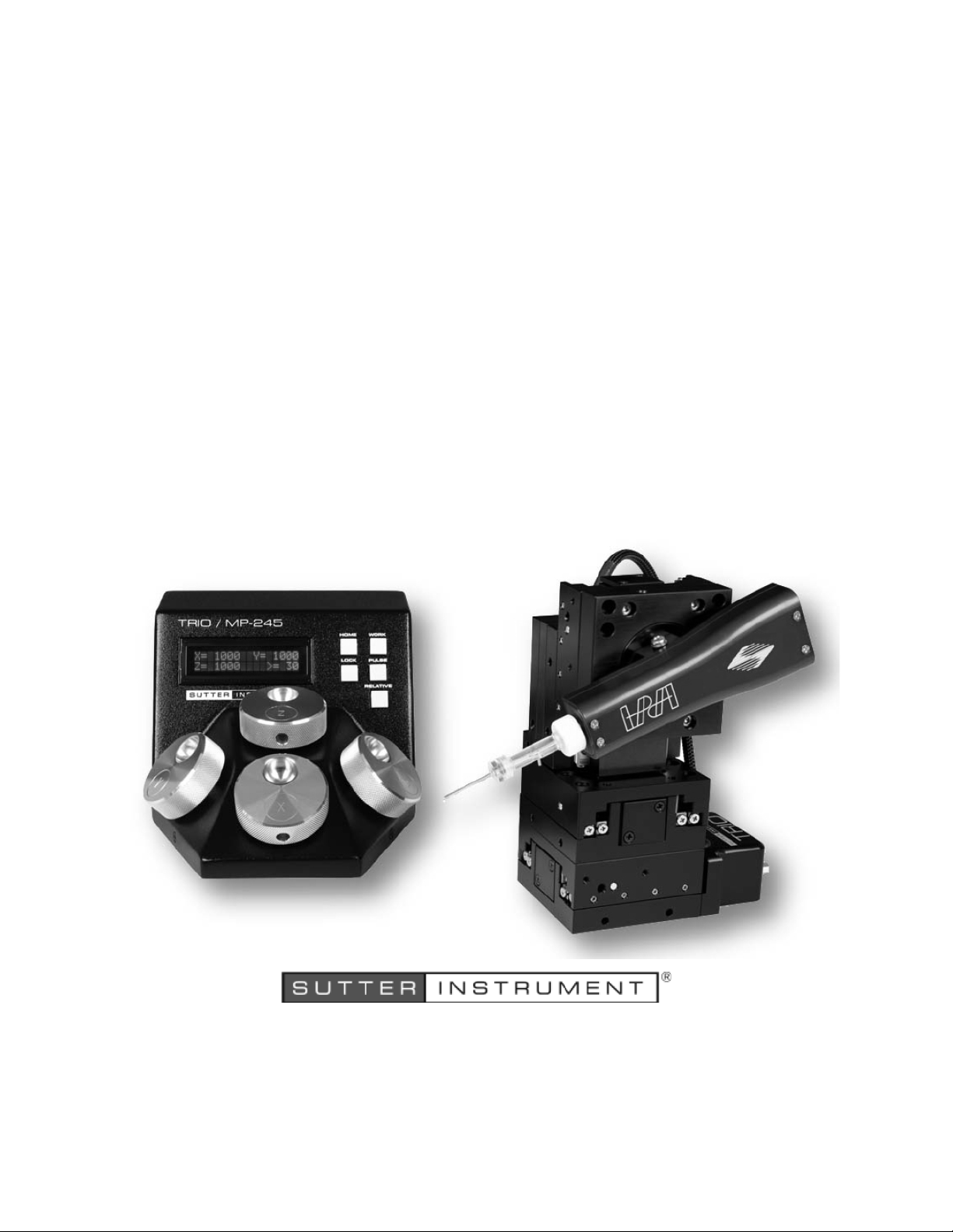
(The picture on the cover page shows a TRIO MP-245A ROE/controller and a TRIO MP-245/M
micromanipulator. The Sutter Instrument IPA Headstage shown mounted on the micromanipulator is not
included in the TRIO MP-245A Series system.)
Copyright © 2019 Sutter Instrument Company. All Rights Reserved.
TRIO™ is a trademark of Sutter Instrument Company.
TRIO MP-245A FOUR-AXIS MICROMANIPULATOR SYSTEM OPERATION MANUAL – REV. 3.12B (20191001)
Page 3
Page 4

Page 5
3
DISCLAIMER
The TRIO MP-245A consists of one electromechanical micromanipulator device and one ROE
(Rotary Optical Encoder) with integrated controller. The purpose of the system is for the
manipulation at the micro level of micropipettes and probes used in conjunction with a
microscope. No other use is recommended.
This instrument is designed for use in a laboratory environment. It is not intended nor
should it be used in human experimentation or applied to humans in any way. This is not a
medical device.
Unless otherwise indicated in this manual or by Sutter Instrument Technical Support for
reconfiguration, do not open or attempt to repair the instrument.
Do not allow an unauthorized and/or untrained operative to use this device.
Any misuse will be the sole responsibility of the user/owner and Sutter Instrument Company
assumes no implied or inferred liability for direct or consequential damages from this
instrument if it is operated or used in any way other than for which it is designed.
SAFETY WARNINGS AND PRECAUTIONS
Electrical
Operate the TRIO MP-245A using 110 – 240 VAC., 50-60 Hz line voltage. This instrument
is designed for use in a laboratory environment that has low electrical noise and
mechanical vibration. Surge suppression is always recommended
NOTE: There are no user-replaceable fuses in the TRIO MP-245A system.
The TRIO MP-245A system’s power supply consists of an external AC to DC
switching power adapter. If the external power adapter is damaged due to a mains over or
under voltage, it must be replaced.
GROUNDING/EARTHING: Proper grounding protects the ROE/controller
electronics, reduces/eliminates electromagnetic interference, and improves the safety of the
system operator. The ROE/controller provides a socket (labeled GROUND) that accepts a
banana plug attached to a suitably gauged insulated wire, the other end of which (alligator
clip) connects to a solid, proper ground.
Avoiding Electrical Shock and Fire-related Injury
Always use the grounded power cord provided to connect the system’s power adapter to a
grounded/earthed mains outlet (3-prong). This is required to protect you from injury in the
event that an electrical hazard occurs.
Do not disassemble the system. Refer servicing to qualified personnel.
To prevent fire or shock hazard do not expose the unit to rain or moisture.
Electromagnetic Interference
To comply with FDA and CE/EU electromagnetic immunity and interference standards; and
to reduce the electromagnetic coupling between this and other equipment in your lab always
use the type and length of interconnect cables provided for interconnecting the electromechanical devices and ROE/controller (refer to Technical Specifications for more details).
Operational
Failure to comply with any of the following precautions may damage this device.
TRIO MP-245A FOUR-AXIS MICROMANIPULATOR SYSTEM OPERATION MANUAL – REV. 3.12B (20191001)
Page 6

4
This instrument is designed for operation in a laboratory environment (Pollution Degree I)
that is free from mechanical vibrations, electrical noise and transients.
DO NOT CONNECT OR DISCONNECT THE CABLES BETWEEN THE
CONTROLLER AND THE MECHANICAL UNITS WHILE POWER IS ON.
Please allow at least 20 seconds after turning the unit off before disconnecting the
mechanical units. Failure to do so may result in damage to the electronics.
Operate this instrument only according to the instructions included in this manual.
Do not operate if there is any obvious damage to any part of the instrument.
Do not operate this instrument near flammable materials. The use of any hazardous
materials with this instrument is not recommended and, if undertaken, is done so at the
users’ own risk.
Do not operate if there is any obvious damage to any part of the instrument. Do not
attempt to operate the instrument with the TRIO MP-245/M electromechanical
manipulator shipping tape in place or severe motor damage may result. When transporting
the mechanical manipulator, be sure to reinstall the shipping tape (using masking tape or
equivalent only) to the original locations. Failure to do this may result in damage to the
motors.
Never touch any part of the micromanipulator electromechanical device while it is in
operation and moving. Doing so can result in physical injury (e.g., fingers can be caught
and pinched between the moving parts of the micromanipulator).
If the TRIO MP-245A system is used in a microinjection environment, please observe
the following. As with most micromanipulation devices, sharp micropipettes can fly out of
their holder unexpectedly. Always take precautions to prevent this from happening. Never
loosen the micropipette holder chuck when the tubing is pressurized, and never point
micropipette holders at yourself or others. Always wear safety glasses when using sharp
glass micropipettes with pressure tubing.
Take care to ensure no cables pass close to the TRIO MP-245/M electromechanical
micromanipulator within the spherical movement limits of all its axes combined.
Other
Retain the original packaging for future transport of the instrument.
Sutter Instrument reserves the right to change specifications without prior notice.
Use of this instrument is for research purposes only.
Handling Micropipettes
Failure to comply with any of the following precautions may result in injury to the users
of this device as well as those working in the general area near the device.
The micropipettes used with this instrument are very sharp and relatively fragile. Avoid
contact with micropipette tips to prevent accidentally impaling oneself.
Always dispose of micropipettes by placing them into a well-marked, spill-proof “sharps”
container.
TRIO MP-245A FOUR-AXIS MICROMANIPULATOR SYSTEM OPERATION MANUAL – REV. 3.12B (20191001)
Page 7

5
TABLE OF CONTENTS
DISCLAIMER ....................................................................................................................................... 3
SAFETY WARNINGS AND PRECAUTIONS .................................................................................... 3
Electrical .................................................................................................................................................. 3
Avoiding Electrical Shock and Fire-related Injury .............................................................................. 3
Electromagnetic Interference ............................................................................................................ 3
Operational .............................................................................................................................................. 3
Other......................................................................................................................................................... 4
Handling Micropipettes .......................................................................................................................... 4
1. INTRODUCTION ............................................................................................................................. 9
1.1 Structure of the TRIO MP-245A Documentation Package ......................................................... 9
1.2 Components of the TRIO MP-245A System .................................................................................. 9
1.3 Overview .......................................................................................................................................... 10
1.3.1 Features ..................................................................................................................................... 10
1.3.2 Description ................................................................................................................................ 10
2. INSTALLATION ............................................................................................................................ 13
2.1 Mounting Instructions ................................................................................................................... 13
2.1.1 Mounting the TRIO MP-245/M to the Stand or Platform .................................................. 13
2.2 Headstage Mounting ...................................................................................................................... 14
2.3 Other Accessories ............................................................................................................................ 14
2.4 Electrical Connections and Initial Operating Instructions ........................................................ 14
2.5 ROE/Controller Rear Panel Controls and Configuration........................................................... 15
2.5.1 Power Switch ............................................................................................................................ 15
2.5.2 Rear-Panel Configuration Switches ....................................................................................... 16
2.5.2.1 Rear-Panel Switches 1, 2, 3 and 4: Knob Rotation Directionality for Forward (+)
Movement ....................................................................................................................................... 16
2.5.2.2 Rear-Panel Switch 5: Y-Axis Lockout during Homing .................................................. 16
2.5.2.3 Rear-Panel Switch 6: Calibration Homing on Power On ............................................. 16
2.5.1 Internal Configuration Switches ............................................................................................ 17
2.5.1.1 Internal Switch 1 Reserved .............................................................................................. 17
2.5.1.2 Internal Switch 2: Electromechanical Device Compatibility. ....................................... 17
2.5.1.3 Internal Switch 3 Reserved .............................................................................................. 17
2.5.1.4 Internal Switch 4 Linear/Nonlinear Manual Operation ............................................... 17
3. OPERATIONS ................................................................................................................................ 19
3.1 Main Controls and Indicators on the ROE/Controller ............................................................... 19
3.2 Display .............................................................................................................................................. 19
3.2.1 Initial Startup ........................................................................................................................... 19
3.3 Control Operations ......................................................................................................................... 20
3.3.1 Maximum Positive Position Values: ...................................................................................... 20
3.3.2 Setting Position for HOME or WORK ................................................................................... 20
3.3.3 Setting the Angle of the Pipette/Headstage Holder ............................................................. 20
3.3.4 Operating the Virtual D Axis .................................................................................................. 20
3.3.5 Moving to the Home Position ................................................................................................. 21
3.3.6 Moving to the Work Position .................................................................................................. 21
TRIO MP-245A FOUR-AXIS MICROMANIPULATOR SYSTEM OPERATION MANUAL – REV. 3.12B (20191001)
Page 8

6
3.3.7 Setting Absolute/Relative Coordinates Mode ........................................................................ 22
3.3.8 Mode Indications ...................................................................................................................... 22
3.3.9 Speed Control and ROE Knob Movements (SPEED) .......................................................... 23
3.3.10 Movement Knobs Disabling and Lock Mode ([SPEED]/LOCK) ...................................... 23
3.3.11 Pausing Home Movements (HOME (while moving to Home)) ........................................ 23
3.3.12 Pausing Work Movements (WORK (while moving to Work)) .......................................... 23
3.3.13 Pulse Mode and Virtual D-Axis Movement (PULSE) ........................................................ 23
3.4 Micropipette/Headstage Exchange ............................................................................................... 23
4. EXTERNAL CONTROL ................................................................................................................ 25
4.1 General ............................................................................................................................................. 25
4.2 Virtual COM Port (VCP) Serial Port Settings ............................................................................. 25
4.3 Protocol and Handshaking ............................................................................................................ 25
4.4 Command Sequence Formatting .................................................................................................. 26
4.5 Axis Position Command Parameters ............................................................................................ 26
4.6 Microsteps and Microns (Micrometers) ........................................................................................ 27
4.7 Commands ....................................................................................................................................... 27
4.7.1 Get Current Position and Angle (‘c’ or ‘C’) Command ........................................................ 27
4.7.2 Move to Controller-Defined HOME Position (‘h’) Command ............................................. 28
4.7.3 Move to Controller-Defined WORK Position (‘w’) Command ............................................ 28
4.7.4 Move to Specified “Home” Position (‘H’) Command ........................................................... 28
4.7.5 Move to Specified “Work” Position (‘W’) Command............................................................ 29
4.7.6 Move in Straight Line to Specified Position at Specified Speed (‘S’) Command .............. 29
4.7.7 Interrupt Straight-Line Move (‘^C’) Command ................................................................. 30
4.7.8 Move to Specified X-Axis Position (‘x’ or ‘X’) Command ..................................................... 30
4.7.9 Move to Specified Y-Axis Position (‘y’ or ‘Y’) Command ..................................................... 31
4.7.10 Move to Specified Z-Axis Position (‘z’ or ‘Z’) Command ................................................... 31
4.7.11 Setting the Angle (‘A’) Command ........................................................................................ 31
4.7.12 Recalibrate (‘R’) Command ................................................................................................... 32
4.7.13 Notes ........................................................................................................................................ 32
5. MAINTENANCE ............................................................................................................................ 35
6. RECONFIGURATION ................................................................................................................... 35
6.1 Changing the Rotary Knob Functions on the ROE/Controller ................................................. 35
APPENDIX A. LIMITED WARRANTY ............................................................................................ 37
APPENDIX B. ACCESSORIES ......................................................................................................... 38
APPENDIX C. TECHNICAL SPECIFICATIONS ........................................................................... 39
APPENDIX D. QUICK REFERENCE .............................................................................................. 41
D.1. Manual Operation ......................................................................................................................... 41
D.2. Configuration................................................................................................................................. 41
Rear-Panel DIP Switches ............................................................................................................... 41
Internal DIP Switches .................................................................................................................... 41
D.3. External Control ........................................................................................................................... 42
INDEX ................................................................................................................................................. 47
TRIO MP-245A FOUR-AXIS MICROMANIPULATOR SYSTEM OPERATION MANUAL – REV. 3.12B (20191001)
Page 9

7
TABLE OF FIGURES
Figure 1-1. The TRIO MP-245A system .................................................................................................. 9
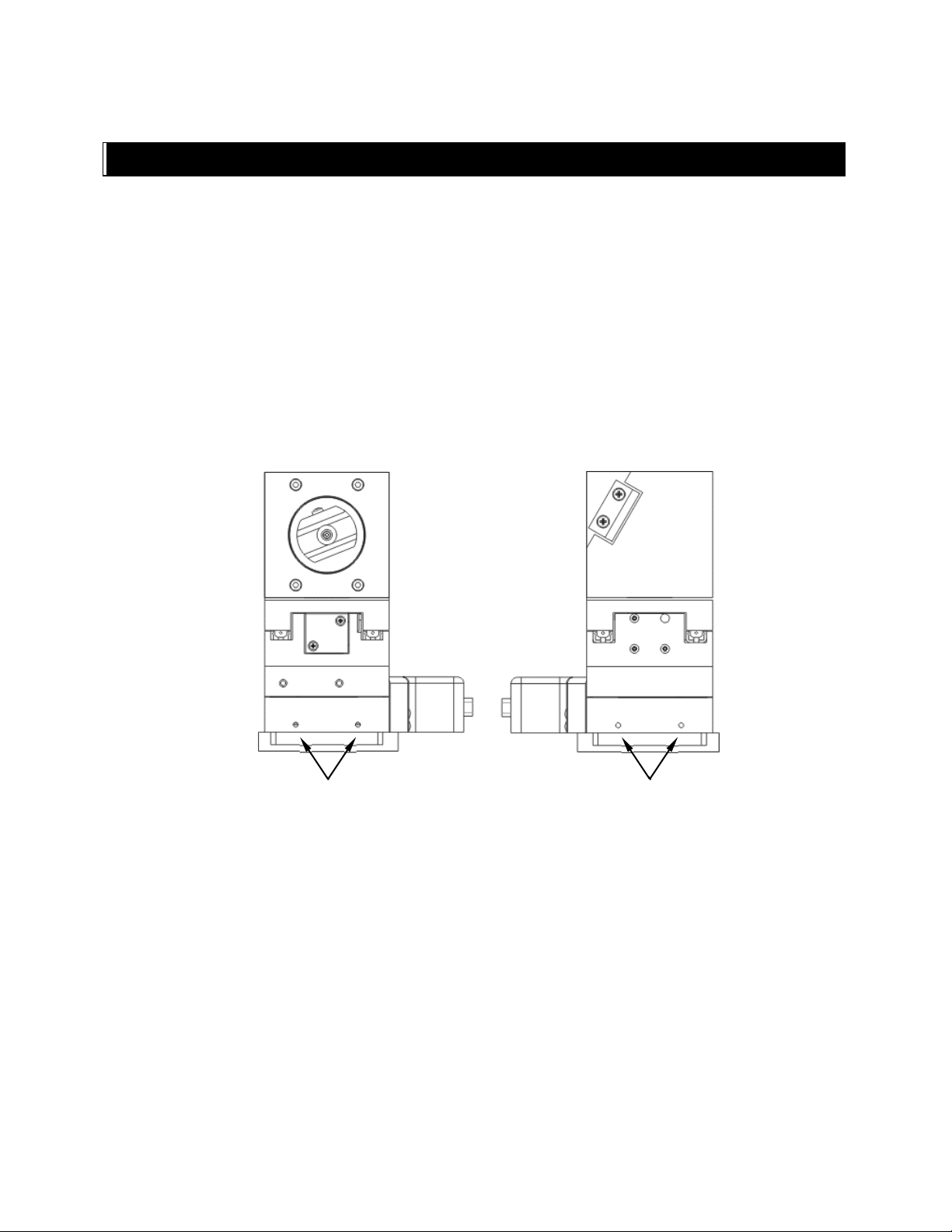
Figure 2-1. Side view of TRIO MP-245/M showing mounting adapter plate and lock screws. ........ 13
Figure 2-2. Mounting the TRIO MP-245/M on the Adapter Plate ...................................................... 14
Figure 2-3. Rear of TRIO MP-245A ROE/Controller cabinet .............................................................. 15
Figure 2-4. Configuration switches on rear-panel (switch positions shown are factory defaults). .. 16
Figure 2-5. Internal configuration switches (switch positions shown are factory defaults). ........... 17
Figure 3-1. LCD Display showing startup screen. ................................................................................ 19
Figure 3-2. Startup screen ....................................................................................................................... 19
Figure 3-3. Factory default startup (Home) position ............................................................................ 20
Figure 3-4. Maximum positive values..................................................................................................... 20
Figure 3-5. Moving to Home position (screen is amber while moving) .............................................. 21
Figure 3-6. Factory default Home position ............................................................................................ 21
Figure 3-7. Example Home position defined and saved ....................................................................... 21
Figure 3-8. Example Work position ........................................................................................................ 21
Figure 3-9. Relative mode ........................................................................................................................ 22
Figure 3-10. Relative mode ...................................................................................................................... 22
Figure 3-11. Absolute mode ..................................................................................................................... 22
Figure 3-12. Angled side view of TRIO MP-245/M to change headstage mount ............................... 24
Figure 6-1. Locations of the axis connectors inside the ROE/Controller ........................................... 35
TABLE OF TABLES
Table 2-1. Rear-Panel Configuration Switches 1 - 4: Configuring the direction of each axis. ......... 16
Table 2-2. Rear-Panel Configuration Switch 5: Y-Axis Homing Movement Lock Out.................... 16
Table 2-3. Rear-Panel Configuration Switch 6: Configuring power-on positional memory or
calibration. ............................................................................................................................... 16
Table 2-4. Internal Configuration Switch 2: Electromechanical device compatibility. .................... 17
Table 3-1. Maximum positive position value of each axis .................................................................... 20
Table 3-2. Screen colors and modes ........................................................................................................ 23
Table 4-1. USB-VCP interface serial port settings. .............................................................................. 25
Table 4-2. Microns/microsteps conversion. ............................................................................................ 27
Table 4-3. Ranges and bounds ................................................................................................................. 27
Table 4-4. Get Current Position and Angle (‘c’ or ‘C’) command. ...................................................... 28
Table 4-5. Move to controller-defined HOME position (‘h’) command. ............................................. 28
Table 4-6. Move to controller -defined WORK position (‘w’) command. ............................................ 28
Table 4-7. Move to specified “Home” position (‘H’) command. .......................................................... 29
Table 4-8. Move to specified “Work” position (‘W’) command. ........................................................... 29
TRIO MP-245A FOUR-AXIS MICROMANIPULATOR SYSTEM OPERATION MANUAL – REV. 3.12B (20191001)
Page 10

8
Table 4-9. Straight-line move to specified position (‘S’) command. .................................................... 29
Table 4-10. Straight-Line Move ‘S’ Command Speeds. ........................................................................ 30
Table 4-11. Interrupt a straight-line move in progress (‘^C’) command. ......................................... 30
Table 4-12. Move to specified X-axis position (‘x’ or ‘X’) command. ................................................... 31
Table 4-13. Move to specified Y-axis position (‘y’ or ‘Y’) command. ................................................... 31
Table 4-14. Move to specified Z-axis position (‘z’ or ‘Z’) command. .................................................... 31
Table 4-15. Set the angle (‘A’) command. .............................................................................................. 32
Table 4-16. Recalibrate (‘R’) command. ................................................................................................. 32
Table 4-16. Straight-Line Move ‘S’ Command Speeds. ........................................................................ 34
Table C-1. TRIO MP-245A cables and receptacles/connectors. ........................................................... 39
Table D-1. Configuration Switches (External) 1 – 6. ............................................................................ 41
Table D-2. Configuration Switches (Internal) 1 - 4 .............................................................................. 41
Table D-3. USB-VCP interface serial port settings............................................................................... 42
Table D-4. Microns/microsteps conversion. ........................................................................................... 43
Table D-5. Ranges and bounds. ............................................................................................................... 43
Table D-6. TRIO MP-245A external control commands. ..................................................................... 43
Table D-7. Straight-Line Move ‘S’ Command Speeds. ......................................................................... 46
TRIO MP-245A FOUR-AXIS MICROMANIPULATOR SYSTEM OPERATION MANUAL – REV. 3.12B (20191001)
Page 11
9
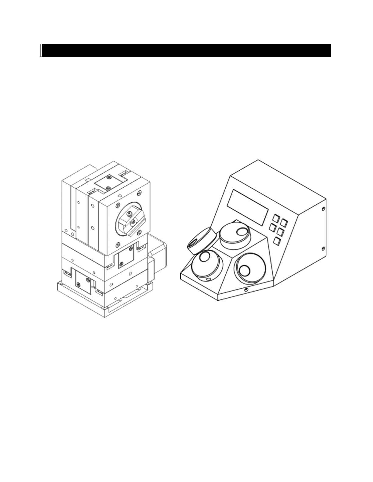
TRIO MP-245/M
TRIO MP-245/E
1. INTRODUCTION
1.1 Structure of the TRIO MP-245A Documentation Package
The TRIO MP-245A 3-Axis Micromanipulator System is comprised of a ROE/controller, a
power adapter, and a TRIO MP-245/M stepper-motor-based electromechanical
micromanipulator. This manual consists of four parts: This chapter, Introduction, which
provides an overview and general description of the TRIO MP-245A system; Chapter 2,
Installation, which describes how to install, set up, and configure all components of the
system; Chapter 3, Operations, which describes how to operate the TRIO MP-245A; Chapter
4, Maintenance, describes how to perform routine and other maintenance; and Chapter 5,
Reconfiguration, describes the reconfiguration possibilities of the TRIO MP-245A system.
ELECTROMECHANICAL
MICROMANIPULATOR
ROE/CONTROLLER
Figure 1-1. The TRIO MP-245A system
1.2 Components of the TRIO MP-245A System
Carefully remove all components from the shipping container. In addition to this manual, the
following should be included:
TRIO MP-245A FOUR-AXIS MICROMANIPULATOR SYSTEM OPERATION MANUAL – REV. 3.12B (20191001)
Page 12

10
TRIO MP-245A ROE Rotary Optical Encoder input device with built-in controller and
external power adapter.
TRIO MP-245/M electromechanical micromanipulator
26-pin HD DSUB cable (connects the ROE/controller to the TRIO MP-245/M
electromechanical micromanipulator).
Power adapter
Power adapter AC mains cable appropriate for your location
Ground/Earth cable
USB Cable
IMPORTANT
Once the TRIO MP-245A system has been unpacked, remove the shipping tape from the
various locations on the TRIO MP-245/M electromechanical micromanipulator. The shipping
tape must be removed before operating the TRIO MP-245A system. If you need to transport
the TRIO MP-245/M in the future, reapply 2 to 3-inch pieces of masking tape to the same
locations. Once the tape has been removed, handle the TRIO MP-245/M with care. The
mechanisms can be damaged if any of the axes are inadvertently moved without the tape in
place.
1.3 Overview
1.3.1 Features
Three independent axes (X, Y, and Z) each with 25mm travel with a virtual fourth axis
(D) for coaxial pipette movement utilizing a tangent function factoring the holder’s angle
and the X and Z axes.
Sub-micron 100nm resolution
Digital display indicates coordinates in relative or absolute
User-friendly, fanless compact controller with ROE preserves bench space
Push button control of multiple functions – work, home, Lock, pulse and relative
Robotic home- and work-position moves for easy automated pipette exchange
1.3.2 Description
The TRIO MP-245A, the newest Sutter Instrument motorized manipulator, is easy to use and
has three independent axes. The X, Y, and Z axes provide 25mm range of motion. D-axis
movement is accomplished virtually using a tangent function of the chosen angle of the
holder and simultaneously moving X and Z. The ROE controller has a digital display and
keys for Home, Work, Pulse, Lock, and Relative. The compact, intuitive controller takes up
minimal bench space, is fan-free, and easy to use.
While the axes provide X and Y orthogonal motion typical of most motorized manipulators,
Sutter has introduced a diagonal axis with the
coaxially at the exact desired angle of approach.
TRIO MP-245A so one can move the electrode
TRIO MP-245A FOUR-AXIS MICROMANIPULATOR SYSTEM OPERATION MANUAL – REV. 3.12B (20191001)
Page 13

11
The TRIO MP-245A’s ROE provides fine control of electrode position and the rate of rotation
of ROE dials for each axis determines the speed of travel. The finest step size is less than
100nm. Five conveniently located buttons on the ROE provide control of all the basic
functions you will need in normal operation (Work, Home, Lock, Relative, and Pulse).
Press and hold WORK (for 3 seconds) to quickly store a work position, tap HOME to move all
axes to an initial location that is useful for changing electrodes, or press and hold the HOME
button (for 3 seconds) to memorize a new HOME position.
When ready to record data, the motor drive electronics can be suppressed by pressing the
LOCK button. In the LOCK mode, the display turns red and ROE input is locked out to avoid
any accidental motion.
Pressing and holding the RELATIVE button for three seconds at any location causes the
display coordinates to all zeroes. When activating relative mode, the display turns blue.
To return to viewing the absolute coordinates, tap the RELATIVE button to toggle back.
Finall y, tapping the PULSE button causes a 3μm advance in the diagonal. This rapid burst of
forward motion can assist in sharp electrode cell penetration.
All the electronics, except for a small power supply, are housed within the TRIO MP-245A
ROE and no separate controller or computer is required.
External computer control of the TRIO MP-245A is possible via the USB connector mounted
on the controller/ROE’s rear panel. The controller’s internal software is programmed with a
defined set of commands allowing for a wide range of micromanipulator/stage movements as
programmed in software residing in an external computer connected via USB.
TRIO MP-245A FOUR-AXIS MICROMANIPULATOR SYSTEM OPERATION MANUAL – REV. 3.12B (20191001)
Page 14

12
(This page intentionally left blank.)
TRIO MP-245A FOUR-AXIS MICROMANIPULATOR SYSTEM OPERATION MANUAL – REV. 3.12B (20191001)
Page 15
13
Locking Screws
Locking Screws
2. INSTALLATION
When installing the TRIO MP-245A system for the first time, it is recommended that the
components of the system be installed in the following order: TRIO MP-245/M
electromechanical micromanipulator first, followed by the TRIO MP-245A/E ROE/Controller.
2.1 Mounting Instructions
The following sections describe how to mount the TRIO MP-245/M manipulator to a stand
using the mounting adapter plate, how to adjust the pipette angle and how to mount
different headstages.
2.1.1 Mounting the TRIO MP-245/M to the Stand or Platform
The TRIO MP-245/M attaches to the mounting adapter plate using four M3.5x6 hex head
locking screws.
Figure 2-1. Side view of TRIO MP-245/M showing mounting adapter plate and lock screws.
The TRIO MP-245/M is shipped with the adapter plate in place. It is attached using four
tapered pegs, along with four locking screws.
To remove it, first loosen the four hex screws that secure the manipulator to the pegs in the
adapter plate. The rear pair is in a similar location in the back of the manipulator. Once the
locking screws are sufficiently loosened, lift the TRIO MP-245/M upwards from the adapter
plate.
Before attaching the adapter plate to the TRIO MP-245/M, you need to decide where to
position the manipulator on your stand/platform. The stand can be any flat surface carrying
¼-20, 10-32, or M6 holes on one-inch centers (such as a Sutter Instrument MT-series stand
or MD series platform).
TRIO MP-245A FOUR-AXIS MICROMANIPULATOR SYSTEM OPERATION MANUAL – REV. 3.12B (20191001)
Page 16
14
Examine the space of the platform onto which installation is to take place. Attach the control
cable to TRIO MP-245/M and move the entire unit around on the platform until the precise
desired position is determined. A small bag containing the necessary hardware to attach the
TRIO MP-245/M to the stand is included.
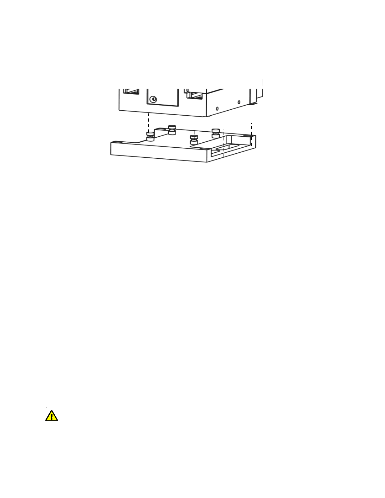
Figure 2-2. Mounting the TRIO MP-245/M on the Adapter Plate
Once the plate is mounted, align the pegs on top of the plate with the holes in the
manipulator, push the X-axis firmly onto the plate, and re-tighten the locking hex set
screws.
2.2 Headstage Mounting
Sutter IPA headstage, Axon headstages 203B or CV-7, and the Heka EPC-10 headstage have
an integral dovetail that fits directly into the rotary dovetail slide bracket on the TRIO MP245/M. The dovetail slide bracket on the TRIO MP-245/M also supports older Axon and Heka
headstages when using the 4’’ dovetail extension.
Rod-mounted headstages and micro tools are accommodated using a rod clamp that fits into
the dovetail (not shown). All the headstage adapters and mounting hardware are included
with the manipulator and are shipped in a zip lock plastic bag.
2.3 Other Accessories
One or more accessories may have been ordered and received for mounting the TRIO MP245/M and/or modifying the headstage mount to the manipulator (i.e., rotating base,
microscope stage mount, gantry, dovetail extension, etc.). Setup of these accessories is
normally covered in documentation accompanying the accessory.
2.4 Electrical Connections and Initial Operating Instructions
Initially, you may want to simply connect the TRIO MP-245/M micromanipulator and the
ROE/Controller together and try some gross movements in order to get a feel for the controls
and how to make simple movements. It is perfectly acceptable to set the manipulators in the
middle of a bench top, make all electrical connections and then observe each unit’s
movement by eye.
CAUTION: Unless the TRIO MP-245/M micromanipulator electromechanical baseplate
is firmly bolted down to a breadboard or solidly to a firm surface, the TRIO MP-245/M is
likely to tip over when fully extending all of its axes, especially if it is loaded with a headstage
that extends beyond the TRIO MP-245/M’s current center of gravity.
TRIO MP-245A FOUR-AXIS MICROMANIPULATOR SYSTEM OPERATION MANUAL – REV. 3.12B (20191001)
Page 17
15
Upon deciding to directly install the TRIO MP-245A system in your rig, it is useful to follow
the initial setup procedure to learn how to move the units to allow easy access to the
mounting screws.
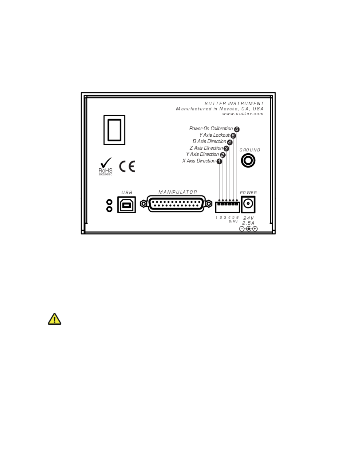
1. With the power switch on the back of the ROE in the OFF (0) position, connect the power
adapter’s 24VDC cable to the POWER receptacle.
Figure 2-3. Rear of TRIO MP-245A ROE/Controller cabinet
2. With the power OFF (rear panel switch in the “0” position), connect a well-
grounded/earthed wire to the GROUND banana plug receptacle.
3. With the power OFF, connect the male end of the DB-25 cable to the MANIPULATOR
connector on the ROE, the other end of which is connected to the TRIO MP-245/M
micromanipulator electromechanical.
(See cautionary note below.)
4. Verify that the six switches on the rear of the ROE are set as desired.
5. Power up the system by moving the power switch on the rear of the ROE to the “1”
position.
* CAUTION: NEVER CONNECT OR DISCONNECT THE ROE/CONTROLLER
FROM THE TRIO MP-245/M WHILE THE POWER IS ON!
2.5 ROE/Controller Rear Panel Controls and Configuration
2.5.1 Power Switch
The power switch for the TRIO MP-245A system is located on the rear panel of the
ROE/controller. At power up, the microprocessor in the ROE/controller scans the attached
equipment and configures the system accordingly.
TRIO MP-245A FOUR-AXIS MICROMANIPULATOR SYSTEM OPERATION MANUAL – REV. 3.12B (20191001)
Page 18

16
Rear-Panel
Switch #
Y-Axis Homing Movement Lock Out
Enabled
Disabled
5
ON (Down)*
Rear-Panel
Switch #
Definition
State
Setting
Position
6
Calibration
Homing on Power
On
Enabled: Calibrates to 1,000 µm for all axes on
power on. Power-off position is forgotten.
ON*
DOWN*
Rear-Panel
Switch #
Axis
Knob Rotation Directionality for Forward (+) Movement
Clockwise
Counterclockwise
1
X
OFF (Up)*
2
Y
OFF (Up)*
3
Z
OFF (Up)*
4
D
OFF (Up)*
1 2 3 4 5 6
2.5.2 Rear-Panel Configuration Switches
Figure 2-4. Configuration switches on rear-panel (switch positions shown are factory defaults).
2.5.2.1 Rear-Panel Switches 1, 2, 3 and 4: Knob Rotation Directionality for Forward (+) Movement
These switches set the directionality for each of the four axes.
Table 2-1. Rear-Panel Configuration Switches 1 - 4: Configuring the direction of each axis.
ON (Down)**
ON (Down)**
ON (Down)
ON (Down)
* Factory default (typical setting for right-hand-mounted manipulator).
** Possible setting for a right-handed manipulator used on the left.
2.5.2.2 Rear-Panel Switch 5: Y-Axis Lockout during Homing
Configures whether the Y axis is locked out while homing.
Table 2-2. Rear-Panel Configuration Switch 5: Y-Axis Homing Movement Lock Out.
OFF (Up)
* Factory default (recommended normal operation setting).
2.5.2.3 Rear-Panel Switch 6: Calibration Homing on Power On
Table 2-3. Rear-Panel Configuration Switch 6: Configuring power-on positional memory or calibration.
* Factory default (recommended normal operation setting)
TRIO MP-245A FOUR-AXIS MICROMANIPULATOR SYSTEM OPERATION MANUAL – REV. 3.12B (20191001)
Disabled: No calibration occurs on power on.
Power-off position is retained on power on
OFF UP
Page 19

17
Internal
Switch #
Definition
State
Setting
Position
2
Eletromechanical
device
compatibility
OFF*
UP*
78
1 2 3 4
2.5.1 Internal Configuration Switches
Figure 2-5. Internal configuration switches (switch positions shown are factory defaults).
2.5.1.1 Internal Switch 1 Reserved
Internal Switch 1 is unused and reserved for future use.
2.5.1.2 Internal Switch 2: Electromechanical Device Compatibility.
Table 2-4. Internal Configuration Switch 2: Electromechanical device compatibility.
MP-845/M, MP-845S/M, & MP-245/M series
MP-285/M series micromanipulator; 3DMS or MT-
stage; MOM & SOM objective mover)
ON DOWN
* Factory default (recommended normal operation setting)
2.5.1.3 Internal Switch 3 Reserved
Internal Switch 3 is unused and reserved for future use.
2.5.1.4 Internal Switch 4 Linear/Nonlinear Manual Operation
Internal Switch 4 switches between linear and nonlinear manual operation. Contact Sutter
Instrument technical support for more information.
TRIO MP-245A FOUR-AXIS MICROMANIPULATOR SYSTEM OPERATION MANUAL – REV. 3.12B (20191001)
Page 20

18
(This page intentionally left blank.)
TRIO MP-245A FOUR-AXIS MICROMANIPULATOR SYSTEM OPERATION MANUAL – REV. 3.12B (20191001)
Page 21

19
DISPLAY
Z-AXIS
CONTROL
Y-AXIS
CONTROL
D-AXIS
CONTROL
(SYN
X-AXIS
CONTROL
RELATIVE
MODE
PULSE &
ANGLE
MODES
WORK
POSITION
HOME
POSITION
SPEED &
LOCK
MODES
TRIO / MP-245A
SUTTER
INSTRUMENT CORP.
(Text in
Green)
TRIO / MP-245A
REV 2.4
(Text in
Green)
3. OPERATIONS
3.1 Main Controls and Indicators on the ROE/Controller
-SET
THETIC)
Figure 3-1. Front view of the TRIO MP-245A ROE/Controller
3.2 Display
3.2.1 Initial Startup
Figure 3-1. LCD Display showing startup screen.
When starting the TRIO MP-245A system for the first time or if the HOME position has not
yet been defined (saved), the values of all four axes will be 1,000 micrometers (microns).
Figure 3-2. Startup screen
TRIO MP-245A FOUR-AXIS MICROMANIPULATOR SYSTEM OPERATION MANUAL – REV. 3.12B (20191001)
Page 22

20
Axis
Maximum Position
Value (in microns)
X
25,000
Y
25,000
Z
25,000
(Text in
Green)
(Text in
Green)
X= 1000 Y= 1000
Z= 1000 >=
X=25000 Y=25000
Z=25000 >=
Figure 3-3. Factory default startup (Home) position
3.3 Control Operations
3.3.1 Maximum Positive Position Values:
Move the dial of an axis clockwise until its position value stops incrementing. The following
table lists the maximum position value (in microns) for each axis.
Table 3-1. Maximum positive position value of each axis
Figure 3-4. Maximum positive values
3.3.2 Setting Position for HOME or WORK
To set position, hold down HOME or WORK button for 3 seconds until beep sounds.
3.3.3 Setting the Angle of the Pipette/Headstage Holder
To change the angle of the holder, first loosen the set screw at the top of the rotary dovetail
bracket, rotate the holder to the desired angle, and then retighten the set sc r e w.
Measure the angle of the holder. (Tip: Many smart phones have an app with a level that can
assist the u s e r. )
3.3.4 Operating the Virtual D Axis
The TRIO MP-245A consists of three physical axes, X, Y and Z. A tangent function utilizing X
and Z axes and the angle of the holder has been implemented to create a virtual D axis. Use
between 10° and 90° for best results.
Zero (0°) is set with the diagonal being parallel to the table and 90° is set with the diagonal
being perpendicular to the table.
To set the angle measured above, on the ROE hold LOCK down for several seconds. The
screen will be red until the display indicates in green: “Select the angle in use (0-90)”.
Use the D dial on the ROE to set the value of the angle. Once this value is dialed in, do not
touch the ROE knob for 8-10 sec. The virtual D angle will now be set.
TRIO MP-245A FOUR-AXIS MICROMANIPULATOR SYSTEM OPERATION MANUAL – REV. 3.12B (20191001)
Page 23

21
X= 0 Y= 1524
Z= 0 >= 0
(Text in
Red)
(Text in
Green)
(Text in
Green)
X= 1000 Y= 1000
Z= 1000 >=
(Text in
Green)
X=1868 Y=1524
Z=1686 >=25
X=2868 Y=2524
Z=1686 >=25
3.3.5 Moving to the Home Position
Figure 3-5. Moving to Home position (screen is amber while moving)
If the Home position has not yet been defined and saved, the Home position values for all
axes will default to 1,000 microns, as shown in the following figure.
Figure 3-6. Factory default Home position
If the Home position has been previously defined (saved), pressing HOME will make a move
to the defined home position (see example in the following figure).
Figure 3-7. Example Home position defined and saved
To move to the Home position, press HOME. If the current position before pressing HOME is
greater than the Home position, the movement will be as follows:
NOTE: Movement to the Home position works only if X coordinates of the HOME position
are less than the WORK position. HOME and WORK positions cannot be the same.
1. Movement begins by retracting the Z axis (at the angle currently set) away from the
sample.
2. Movement then continues along the X axis toward the Home position.
3. The final movement is along the Y-axis towards the operator and away from the
microscope.
NOTE: Step 3 occurs only if “Y-Lockout” is disabled. Otherwise, no movement along the Yaxis occurs.
3.3.6 Moving to the Work Position
Figure 3-8. Example Work position
To move to the Work position, press the WORK button. If the current position before
pressing WORK is less than the Work position, the movement will be as follows:
TRIO MP-245A FOUR-AXIS MICROMANIPULATOR SYSTEM OPERATION MANUAL – REV. 3.12B (20191001)
Page 24

22
X=- 893 Y= 1524
Z= 1686 >= 30
(Text in
Green)
X=- 893 Y= 1524
Z= 1686 >= 30
(Text in
Blue)
X=- 0 Y= 0
Z= 0 >= 0
(Text in
Blue)
1. Movement travels along the Y-axis away from the operator and towards the microscope.
2. Movement is then made along the X axis toward the sample. Travel then continues along
the diagonal until reaching its end-of-travel point.
NOTE: Step 1 occurs only if “Y-Lockout” is disabled. Otherwise, movement begins with
Step 2.
3.3.7 Setting Absolute/Relative Coordinates Mode
The RELATIVE button toggles between Relative and Absolute coordinate systems. The
default coordinate system on power up is Absolute, with the coordinates on the screen shown
in green. To switch to relative coordinates, press the RELATIVE button once. To reset the
current position to all zeroes, depress the RELATIVE for 3 seconds or until a beep is heard,
and then release the button. This resets the current position to all zeroes.
Press RELATIVE once (briefly for < 2 sec.)
Figure 3-9. Relative mode
Depress RELATIVE for 3 sec. or until beep sounds
Figure 3-10. Relative mode
Pressing RELATIVE briefly while in Relative mode, returns displayed coordinates back to
Absolute mode
Figure 3-11. Absolute mode
3.3.8 Mode Indications
The TRIO MP-245A system has three modes of operation: Absolute coordinates, Relative
coordinates, and Lock mode. The display turns color for each specific mode, as shown in the
following table.
TRIO MP-245A FOUR-AXIS MICROMANIPULATOR SYSTEM OPERATION MANUAL – REV. 3.12B (20191001)
Page 25

23
Screen Color
Mode
Example
Green
Absolute Coordinates
Blue
Relative Coordinates
Red
Knobs disabled during move to
X=- 0 Y= 0
Z= 0 >= 0
X= 1868 Y= 1524
Z= 1686 >= 2706
X= 0 Y= 1524
Z= 0 >= 0
Table 3-2. Screen colors and modes
Home or Work position, while in
Lock mode.
3.3.9 Speed Control and ROE Knob Movements (SPEED) The rate at which the ROE axis knobs move the electromechanical can be adjusted with the
SPEED button. Each press of the button cycles through four speeds: 0 (normal) through 3
(fastest).
3.3.10 Movement Knobs Disabling and Lock Mode ([SPEED]/LOCK) Axis-movement knobs are disabled during movements to Home, Work, or while in Lock Mode
(display is in red).
3.3.11 Pausing Home Movements (HOME (while moving to Home)) After Move to Home has been initiated, and while the move is in progress, pressing HOME a
second time pauses the manipulator. Pressing HOME again resumes movement.
3.3.12 Pausing Work Movements (WORK (while moving to Work)) After Move to Work has been initiated, and while the move is in progress, pressing WORK a
second time pauses the manipulator. Pressing WORK again resumes movement.
3.3.13 Pulse Mode and Virtual D-Axis Movement (PULSE)
Pulse mode advances the D axis in 2.85 µm steps. Each press of the PULSE button
increments the Diagonal axis by one 2.85-µm step beyond the current position. This feature
can be used to penetrate tough or resistant tissue.
3.4 Micropipette/Headstage Exchange
Mounted on the front of the Z-axis of the manipulator is the angle-control plate for the
headstage mount.
TRIO MP-245A FOUR-AXIS MICROMANIPULATOR SYSTEM OPERATION MANUAL – REV. 3.12B (20191001)
Page 26

24
Rotary dovetail holder
Rotary dovetail
Rotary dovetail angle
lock set screw
clamp screw
for rod/micropipette
holder or headstage
Figure 3-12. Angled side view of TRIO MP-245/M to change headstage mount
To change the headstage, loosen the screw in the center of the holding bracket. Slide the
headstage upward out of the dovetail groove. Make any adjustments needed of the headstage,
and then tighten down (but do not over tighten) the lock screw in the center of the holding
bracket.
TRIO MP-245A FOUR-AXIS MICROMANIPULATOR SYSTEM OPERATION MANUAL – REV. 3.12B (20191001)
Page 27

25
Property
Setting
4. EXTERNAL CONTROL
4.1 General
Controlling the TRIO MP-245A externally via computer is accomplished by sending
commands over the USB interface between the computer and the USB connector on the rear
panel of the TRIO MP-245A controller/ROE. The USB device driver for Windows is
downloadable from Sutter Instrument’s web site (www.sutter.com
requires Sutter Instrument’s USB CDM (Combined Driver Model) Version 2.10.00 or higher.
The CDM device driver consists of two device drivers: 1) USB device driver, and 2) VCP
(Virtual COM Port) device driver. Install the USB device driver first, followed by the VCP
device driver. The VCP device driver provides a serial RS-232 I/O interface between a
Windows application and the TRIO MP-245A. Although the VCP device driver is optional, its
installation is recommended even if it is not going to be used. Once installed, the VCP can be
enabled or disabled.
The CDM device driver package provides two I/O methodologies over which communications
with the controller over USB can be conducted: 1) USB Direct (D2XX mode), or 2) Serial RS232 asynchronous via the VCP device driver (VCP mode). The first method requires that the
VCP device driver not be installed, or if installed, that it be disabled. The second method
requires that the VCP be installed and enabled.
). The TRIO MP-245A
4.2 Virtual COM Port (VCP) Serial Port Settings
The following table lists the required RS-232 serial settings for the COM port (COM3,
COM5, etc.) generated by the installation or enabling of the VCP device driver.
Table 4-1. USB-VCP interface serial port settings.
Data (“Baud”) Rate (bits per second (bps)) 57600
Data Bits 8
Stop Bits 1
Parity None
Flow Control None
The settings shown in the above table can be set in the device driver’s properties (via the
Device Manager if in Windows) and/or programmatically in your application.
4.3 Protocol and Handshaking
Command sequences do not have terminators. All commands return an ASCII CR (Carriage
Return; 13 decimal, 0D hexadecimal) to indicate that the task associated with the command
has completed. When the controller completes the task associated with a command, it sends
ASCII CR back to the host computer indicating that it is ready to receive a new command. If
a command returns data, the last byte returned is the task-completed indicator.
TRIO MP-245A FOUR-AXIS MICROMANIPULATOR SYSTEM OPERATION MANUAL – REV. 3.12B (20191001)
Page 28

26
4.4 Command Sequence Formatting
Each command sequence consists of at least one byte, the first of which is the “command
byte”. Those commands that have parameters or arguments require a sequence of bytes that
follow the command byte. No delimiters are used between command sequence arguments,
and command sequence terminators are not used. Although most command bytes can be
expressed as ASCII displayable/printable characters, the rest of a command sequence must
generally be expressed as a sequence of unsigned byte values (0-255 decimal; 00 – FF
hexadecimal, or 00000000 – 11111111 binary). Each byte in a command sequence
transmitted to the controller must contain an unsigned binary value. Attempting to code
command sequences as “strings” is not advisable. Any command data returned by the
controller should be initially treated as a sequence of unsigned byte values upon reception.
Groups of contiguous bytes can later be combined to form larger values, as appropriate (e.g.,
2 bytes into 16-bit “word”, or 4 bytes into a 32-bit “long” or “double word”). For the TRIO
MP-245A, all axis position values (number of microsteps) are stored as “unsigned long” 32-bit
positive-only values, and each transmitted and received to and from the controller as four
contiguous bytes.
4.5 Axis Position Command Parameters
All axis positional information is exchanged between the controller and the host computer in
terms of microsteps. Conversion between microsteps and microns (micrometers) is the
responsibility of the software running on the host computer (see Microns/microsteps
conversion table for conversion factors).
Microsteps are stored as positive 32-bit values (“long” (or optionally, “signed long”), or
“unsigned long” for C/C++; “I32” or “U32” for LabVIEW). “Unsigned” means the value is
always positive; negative values are not allowed. The positive-only values can also be stored
in signed type variables, in which case care must be taken to ensure that only positive values
are exchanged with the controller.
The 32-bit value consists of four contiguous bytes, with a byte/bit-ordering format of Little
Endian (“Intel”) (most significant byte (MSB) in the first byte and least significant (LSB) in
the last byte). If the platform on which your application is running is Little Endian, then no
byte order reversal of axis position values is necessary. Examples of platforms using Little
Endian formatting include any system using an Intel/AMD processor (including Microsoft
Windows and Apple Mac OS X).
If the platform on which your application is running is Big Endian (e.g., Motorola PowerPC
CPU), then these 32-bit position values must have their bytes reverse-ordered after receiving
from, or before sending to, the controller. Examples of Big-Endian platforms include many
non-Intel-based systems, LabVIEW (regardless of operating system & CPU), and Java
(programming language/environment). MATLAB and Python (script programming language)
are examples of environments that adapt to the system on which each is running, so LittleEndian enforcement may be needed if running on a Big-Endian system. Some processors
(e.g., ARM) can be configured for specific endianess.
TRIO MP-245A FOUR-AXIS MICROMANIPULATOR SYSTEM OPERATION MANUAL – REV. 3.12B (20191001)
Page 29

27
Controller with Device
From/To Units
Conversion Factor
(multiplier)
MP-845/M, MP-845S/M,
MP-245/M*
micromanip
µm µsteps
10.66666666667
MP-285/M
3DMS
MT-78
stag
MOM
SOM
µm µsteps
8
Device
Axis
Millimeters
Microns
Microsteps
MP-845/M, MP-845S/M, or
MP-245/M* micromanipulator
MP-285/M micro-manipulator;
3DMS
MT-78
MOM
SOM objective mover
4.6 Microsteps and Microns (Micrometers)
All coordinates sent to and received from the controller are in microsteps. To convert
between microsteps and microns (micrometers), use the following conversion factors
(multipliers):
Table 4-2. Microns/microsteps conversion.
or
µsteps µm 0.09375
ulator
micromanipulator;
e;
* DB25 to DB26HD adapter required for MP-245/M.
or
objective mover
or
µsteps µm 0.125
For accuracy in your application, type these conversion factors as “double” (avoid using the
“float” type as it lacks precision with large values). When converting to microsteps, type the
result as a 32-bit “long”, “signed long”, or “I32” integer. When converting to microns, type
the result as “double” (64-bit double-precision floating-point values).
Table 4-3. Ranges and bounds
X, Y, & Z 0 – 25 0 – 25,000 0 – 266,667
or
* DB25 to DB26HD adapter required for MP-245/M.
NOTE: Origin is a physical position of travel that defines the center of the absolute position coordinate system (i.e., absolute
position 0).
Physical Positions: BOT (Beginning Of Travel), COT (Center Of Travel), & EOT (End Of Travel).
In the TRIO MP-245A, the Origin is fixed at BOT.
NOTE: Travel length of each axis is automatically determined by end-of-travel sensor.
stage;
or
X, Y, & Z 0 – 25 0 – 25,000 0 – 200,000
4.7 Commands
4.7.1 Get Current Position and Angle (‘c’ or ‘C’) Command
This command is used to obtain the current position (X, Y, & Z coordinates) of the
manipulator or stage and the current angle setting. The command sequence consists of one
byte as shown in the following table. The data received consists of fourteen bytes containing
X, Y, & Z position (32-bit) values in microsteps (4 bytes each), the angle in degrees (1 byte),
and the completion indicator (1 byte).
TRIO MP-245A FOUR-AXIS MICROMANIPULATOR SYSTEM OPERATION MANUAL – REV. 3.12B (20191001)
Page 30

28
Tx/-
Delay/-
Rx
Ver.
Total
Bytes
Byte
Offset
(Len.)
Value
Alt-
key-
pad #
Ctrl-
char
ASCII
def./char.
Description
Dec.
Hex.
Binary
Tx
All
1 0 99
67
63
43
0110 0011
0100 0011
0099
0043
‘c’
‘C’
Command
Rx.
All
0 (4)
X pos. in µsteps
4 (4)
Y pos. in µsteps
8 (4)
Z pos. in µsteps
12
0
90
00
5A
0000 0000
0101 1010
<NUL>
‘z’
Angle in degrees
13
13
0D
0000 1101
^M
<CR>
Completion indicator
Tx/-
Delay/-
Rx
Ver.
Total
Bytes
Byte
Offset
(Len.)
Value
Alt-
key-
pad #
Ctrl-
char
ASCII
def./char.
Description
Dec.
Hex.
Binary
Tx
All
1 0 104
68
0110 1000
0104
‘h’
Command
Rx
All
1 0 13
0D
0000 1101
<CR>
Completion indicator
Tx/-
Delay/-
Rx
Ver.
Total
Bytes
Byte
Offset
(Len.)
Value
Alt-key-
pad #
Ctrl-
char
ASCII
def./char.
Description
Dec.
Hex.
Binary
Tx
1 0 119
77
0111 0111
0119
‘w’
Command
Rx
1 0 13
0D
0000 1101
<CR>
Completion indicator
Table 4-4. Get Current Position and Angle (‘c’ or ‘C’) command.
or
-
or
-
or
-
or
or
-
4.7.2 Move to Controller-Defined HOME Position (‘h’) Command
moves to the position saved by the controller’s HOME button. X & Z move first (angle
determines order and simultaneity), and Y last.Table 4-5. Move to controller-defined HOME position
(‘h’) command.
4.7.3 Move to Controller-Defined WORK Position (‘w’) Command
moves to the position saved by the controller’s WORK button. Y moves first, and X & Z last
(angle determines order/simultaneity)Table 4-6. Move to controller -defined WORK position (‘w’)
command.
4.7.4 Move to Specified “Home” Position (‘H’) Command
This command instructs the controller to move all 3 axes to specified position, moving X & Z
(angle determines order/simultaneity), and
Y last (see
Ranges
table).
TRIO MP-245A FOUR-AXIS MICROMANIPULATOR SYSTEM OPERATION MANUAL – REV. 3.12B (20191001)
Page 31

29
Tx/-
Delay/-
Rx
Ver.
Total
Bytes
Byte
Offset
(Len.)
Value
Alt-key-
pad #
Ctrl-
char
ASCII
def./char.
Description
Dec.
Hex.
Binary
Tx
All
13 0 72
48
0100 1000
0072
‘H’
Command
1 (4)
X µsteps
5 (4)
Y µsteps
9 (4)
Z µsteps
Rx
All
1 0 13
0D
0000 1101
^M
<CR>
Completion indicator
Tx/-
Delay/-
Rx
Ver.
Total
Bytes
Byte
Offset
(Len.)
Value
Alt-key-
pad #
Ctrl-
char
ASCII
def./char.
Description
Dec.
Hex.
Binary
Tx
All
13 0 87
57
0101 0111
0087
‘W’
Command
1 (4)
X µsteps
5 (4)
Y µsteps
9 (4)
Z µsteps
Rx
All
1 0 13
0D
0000 1101
^M
<CR>
Completion indicator
Tx/-
Delay/-
Rx
Ver.
Total
Bytes
Byte
Offset
(Len.)
Value
Alt-key-
pad #
Ctrl-
char
ASCII
def./char.
Description
Dec.
Hex.
Binary
Tx
All
14 0 83
53
1001 0111
0083
‘S’
Command
1 15
0
0F
00
0000 1111
0000 0000
0015
0000
^O
^@
Speed (15 – 0 (fastest
2 (4)
X µsteps
6 (4)
Y µsteps
10(4)
Z µsteps
Rx
All
1 0 13
0D
0000 1101
^M
<CR>
Completion indicator
Table 4-7. Move to specified “Home” position (‘H’) command.
4.7.5 Move to Specified “Work” Position (‘W’) Command
This command instructs the controller to move all 3 axes to specified position, moving Y first,
and X & Z last (angle determines order/simultaneity) (see
Table 4-8. Move to specified “Work” position (‘W’) command.
Ranges
table).
4.7.6 Move in Straight Line to Specified Position at Specified Speed (‘S’) Command
This command instructs the controller to move all three axes simultaneously in a straight
line to specified position (see
Ranges
table). The command sequence consists of seventeen
bytes.
Table 4-9. Straight-line move to specified position (‘S’) command.
-
-
-
-
-
through slowest))
While all move commands cause movement to occur at a rate of 5,000 microns/second, the
“Straight-Line Move ‘S’ command is specified with one of sixteen speeds. Actual speed for the
can be determined with the following formula: (5000 / 16) * (sp +1), where 5,000 is the
TRIO MP-245A FOUR-AXIS MICROMANIPULATOR SYSTEM OPERATION MANUAL – REV. 3.12B (20191001)
Page 32

30
Speed Setting
(2nd Argument of ‘S’
Command Seq.)
mm/sec
or
µm/ms
µm/sec
or
nm/ms
nm/sec
in/sec
or
mil/ms
Percentage
of
Maximum
15
5.0000
5000.0
5000000
0.196850394
100.00%
14
4.6875
4687.5
4687500
0.184547244
93.75%
13
4.3750
4375.0
4375000
0.172244094
87.50%
12
4.0625
4062.5
4062500
0.159940945
81.25%
11
3.7500
3750.0
3750000
0.147637795
75.00%
10
3.4375
3437.5
3437500
0.135334646
68.75%
9
3.1250
3125.0
3125000
0.123031496
62.50%
8
2.8125
2812.5
2812500
0.110728346
56.25%
7
2.5000
2500.0
2500000
0.098425197
50.00%
6
2.1875
2187.5
2187500
0.086122047
43.75%
5
1.8750
1875.0
1875000
0.073818898
37.50%
4
1.5625
1562.5
1562500
0.061515748
31.25%
3
1.2500
1250.0
1250000
0.049212598
25.00%
2
0.9375
0937.5
937500
0.036909449
18.75%
1
0.6250
0625.0
625000
0.024606299
12.50%
0
0.3125
0312.5
312500
0.012303150
6.25%
Tx/-
Delay/-
Rx
Ver.
Total
Bytes
Byte
Offset
(Len.)
Value
Alt-key-
pad #
Ctrl-
char
ASCII
def./char.
Description
Dec.
Hex.
Binary
Tx
All 1 0 3 03
0000 0011
0003
^C
<ETX>
Command
Rx
1 0
13
0D
0000 1101
<CR>
Completion indicator
maximum speed in microns/second and “sp” is the speed level 0 (slowest) through 15
(fastest). For mm/second or microns/millisecond, multiply result by 0.001.
Table 4-10. Straight-Line Move ‘S’ Command Speeds.
4.7.7 Interrupt Straight-Line Move (‘^C’) Command
This command interrupts a move in progress (only for moves initiated by the “Straight-line”
move (‘S’) command). The command sequence consists of one byte.
Table 4-11. Interrupt a straight-line move in progress (‘^C’) command.
4.7.8 Move to Specified X-Axis Position (‘x’ or ‘X’) Command
This command moves to a specified position for only the X-axis.
TRIO MP-245A FOUR-AXIS MICROMANIPULATOR SYSTEM OPERATION MANUAL – REV. 3.12B (20191001)
Page 33

31
Tx/-
Delay/-
Rx
Ver.
Total
Bytes
Byte
Offset
(Len.)
Value
Alt-
key-
pad #
Ctrl-
char
ASCII
def./char.
Description
Dec.
Hex.
Binary
Tx
All 5 0
120
90
78
5A
0111 1000
0101 1010
0120
0090
‘x’
‘X’
Command
1 (4)
X µsteps
Rx
1 0
13
0D
0000 1101
<CR>
Completion indicator
Tx/-
Delay/-
Rx
Ver.
Total
Bytes
Byte
Offset
(Len.)
Value
Alt-
key-
pad #
Ctrl-
char
ASCII
def./char.
Description
Dec.
Hex.
Binary
Tx
All 5 0
121
91
79
5B
0111 1001
0101 1011
0121
0091
‘y’
‘Y’
Command
1 (4)
Y µsteps
Rx
1 0
13
0D
0000 1101
<CR>
Completion indicator
Tx/-
Delay/-
Rx
Ver.
Total
Bytes
Byte
Offset
(Len.)
Value
Alt-
key-
pad #
Ctrl-
char
ASCII
def./char.
Description
Dec.
Hex.
Binary
Tx
All 5 0
122
92
7A
5C
0111 1010
0101 1100
0122
0092
‘z’
‘Z’
Command
1 (4)
Z µsteps
Rx
1 0
13
0D
0000 1101
<CR>
Completion indicator
Table 4-12. Move to specified X-axis position (‘x’ or ‘X’) command.
or
or
or
or
or
4.7.9 Move to Specified Y-Axis Position (‘y’ or ‘Y’) Command
This command moves to a specified position for only the Y-axis.
Table 4-13. Move to specified Y-axis position (‘y’ or ‘Y’) command.
or
or
or
or
or
4.7.10 Move to Specified Z-Axis Position (‘z’ or ‘Z’) Command
This command moves to a specified position for only the Z-axis.
Table 4-14. Move to specified Z-axis position (‘z’ or ‘Z’) command.
or
or
or
or
or
4.7.11 Setting the Angle (‘A’) Command
Sets the angle value, in degrees, to match the angle position of the rotary dovetail
TRIO MP-245A FOUR-AXIS MICROMANIPULATOR SYSTEM OPERATION MANUAL – REV. 3.12B (20191001)
Page 34

32
Tx/-
Delay/-
Rx
Ver.
Total
Bytes
Byte
Offset
(Len.)
Value
Alt-
key-
pad #
Ctrl-
char
ASCII
def./char.
Description
Dec.
Hex.
Binary
Tx
All 2 0
65
41
1010 1001
0065
‘A’
Command
1
0
90
00
5A
0000 0000
0101 1010
0000
0090
<NUL>
‘z’
Angle in degrees between 0 and
Movement
Rx
1 0
13
0D
0000 1101
<CR>
Completion indicator
Tx/-
Delay/-
Rx
Ver.
Total
Bytes
Byte
Offset
(Len.)
Value
Alt-
key-
pad #
Ctrl-
char
ASCII
def./char.
Description
Dec.
Hex.
Binary
Tx
All 1 0
82
62
1000 0010
0082
‘R’
Command
Rx
1 0
13
0D
0000 1101
<CR>
Completion indicator
Table 4-15. Set the angle (‘A’) command.
-
-
-
-
-
90. See
Angle Setting &
note
4.7.12 Recalibrate (‘R’) Command
Recalibrates the connected micromanipulator/stage to 1,000 microns in each axis.
Table 4-16. Recalibrate (‘R’) command.
4.7.13 Notes
1. Task-Complete Indicator: All commands will send back to the computer the “TaskComplete Indicator” to signal the command and its associated function in controller is
complete. The indicator consists of one (1) byte containing a value of 13 decimal (0D
hexadecimal), and which represents an ASCII CR (Carriage Return).
2. Intercommand Delay: A short delay (usually around 2 ms) is recommended between
commands (after sending a command sequence and before sending the next command).
3. Clearing Send/Receive Buffers: Clearing (purging) the transmit and receive buffers of the
I/O port immediately before sending any command is recommended.
4. Positions in Microsteps: All positions sent to and received from the controller are in
microsteps (µsteps). See
Microns/-microsteps conversion
table) for conversion between
µsteps and microns (micrometers (µm)).
5. Ranges and Bounds: See
Ranges and Bounds
table for exact minimum and maximum
values for each axis of each compatible device that can be connected. All move commands
must include positive values only for positions – negative positions must never be
specified. All positions are absolute as measured from the physical beginning of travel of
a device’s axis. In application programming, it is important that positional values be
checked (>= 0 and <= max.) to ensure that a negative absolute position is never sent to
the controller and that end of travel is not exceeded. All computational relative
positioning must always resolve to accurate absolute positions.
6. Absolute Positioning System Origin: The Origin is set to a physical position of travel to
define absolute position 0. The physical Origin position is fixed at beginning of travel
(BOT). This means that all higher positions (towards end of travel (EOT)) are positive
values; there are no lower positions and therefore no negative values are allowed.
TRIO MP-245A FOUR-AXIS MICROMANIPULATOR SYSTEM OPERATION MANUAL – REV. 3.12B (20191001)
Page 35

33
7. Absolute vs. Relative Positioning: Current position (‘c’) and move commands always use
absolute positions. All positions can be considered “relative” to the Origin (Position 0),
but all are in fact absolute positions. Any position that’s considered to be “relative” to the
current position, whatever that might be, can be handled synthetically by external
programming. However, care should be taken to ensure that all relative positions are
accurately translated to correct absolute positions before initiating a move command.
8. Position Value Typing: All positions sent and received to and from the controller are in
microsteps and consist of 32-bit integer values (four contiguous bytes). Position values
can be either positive or negative, so type must be “signed”. Although each positional
value is transmitted to, or received from, the controller as a sequence of four (4)
contiguous bytes, for computer application computational and storage purposes each
should be typed as a signed integer (“long” or “signed long” in C/C++; “I32” in
LabVIEW, etc.). Note that in Python, incorporating the optional NumPy package brings
robust data typing like that used in C/C++ to your program, simplifying coding and
adding positioning accuracy to the application.
9. Position Value Bit Ordering: All 32-bit position values transmitted to, and received from,
the controller must be bit/byte-ordered in “Little Endian” format. This means that the
least significant bit/byte is last (last to send and last to receive). Byte-order reversal may
be required on some platforms. Microsoft Windows, Intel-based Apple Macintosh systems
running Mac OS X, and most Intel/AMD processor-based Linux distributions handle byte
storage in Little-Endian byte order so byte reordering is not necessary before converting
to/from 32-bit “long” values. LabVIEW always handles “byte strings” in “Big Endian”
byte order irrespective of operating system and CPU, requiring that the four bytes
containing a microsteps value be reverse ordered before/after conversion to/from a
multibyte type value (I32, U32, etc.). MATLAB automatically adjusts the endianess of
multibyte storage entities to that of the system on which it is running, so explicit byte
reordering is generally unnecessary unless the underlying platform is Big Endian. If your
development platform does not have built-in Little/Big Endian conversion functions, bit
reordering can be accomplished by first swapping positions of the two bytes in each 16-bit
half of the 32-bit value, and then swap positions of the two halves. This method
efficiently and quickly changes the bit ordering of any multibyte value between the two
Endian formats (if Big Endian, it becomes Little Endian, and if Little Endian, it becomes
then Big Endian).
10. Travel Lengths and Durations: “Move” commands might have short to long distances of
travel. If not polling for return data, an appropriate delay should be inserted between the
sending of the command sequence and reception of return data so that the next command
is sent only after the move is complete. This delay can be auto calculated by determining
the distance of travel (difference between current and target positions) and rate of travel.
This delay is not needed if polling for return data. In either case, however, an appropriate
timeout must be set for the reception of data so that the I/O does not time out before the
move is made and/or the delay expires.
11. Movement Speeds: All move commands cause movement to occur at a rate of 5,000
microns/second, except for the “Straight-Line Move ‘S’ command which can be specified
with one of sixteen speeds. Actual speed for the “Straight-Line Move ‘S’ command can be
determined with the following formula: (5000 / 16) * (sp +1), where 5,000 is the
maximum speed in microns/second and “sp” is the speed level 0 (slowest) through 15
(fastest). For mm/second or microns/millisecond, multiply result by 0.001.
TRIO MP-245A FOUR-AXIS MICROMANIPULATOR SYSTEM OPERATION MANUAL – REV. 3.12B (20191001)
Page 36

34
Speed
Setting
mm/sec
or
µm/ms
µm/sec
or
nm/ms
nm/sec
in/sec
or
mil/ms
% of
Max.
15
5.0000
5000.0
5000000
0.196850394
100.00%
14
4.6875
4687.5
4687500
0.184547244
93.75%
13
4.3750
4375.0
4375000
0.172244094
87.50%
12
4.0625
4062.5
4062500
0.159940945
81.25%
11
3.7500
3750.0
3750000
0.147637795
75.00%
10
3.4375
3437.5
3437500
0.135334646
68.75%
9
3.1250
3125.0
3125000
0.123031496
62.50%
8
2.8125
2812.5
2812500
0.110728346
56.25%
7
2.5000
2500.0
2500000
0.098425197
50.00%
6
2.1875
2187.5
2187500
0.086122047
43.75%
5
1.8750
1875.0
1875000
0.073818898
37.50%
4
1.5625
1562.5
1562500
0.061515748
31.25%
3
1.2500
1250.0
1250000
0.049212598
25.00%
2
0.9375
0937.5
937500
0.036909449
18.75%
1
0.6250
0625.0
625000
0.024606299
12.50%
Table 4-17. Straight-Line Move ‘S’ Command Speeds.
12. Move Interruption: A command should be sent to the controller for a manipulator only
after the task of any previous command is complete (i.e., the task-completion terminator
(CR) is returned associated). One exception is the “Interrupt Move” (^C) command,
which can be issued while an ‘S’ command-initiated move is still in progress.
13. Angle Setting & Movement: Although the set angle command allows for a range of 0° to
90°, the effective range that allows full movement is 1° to 89° (>0° and <90°). If 0° or 90°,
Z or X axis fails to move, causing single- and multi-axis movement commands to fail. The
ideal range for smooth movement is 10° to 80°. Factory default is 30°.
TRIO MP-245A FOUR-AXIS MICROMANIPULATOR SYSTEM OPERATION MANUAL – REV. 3.12B (20191001)
Page 37

35
5. MAINTENANCE
Routine cleaning of the TRIO MP-245A system is required to prevent excessive dust
accumulations. Wipe all exterior surfaces with a dry, soft, cotton cloth.
Periodically inspect all cables and connections to make sure that all connections are made
well and that all connectors are well and evenly seated.
6. RECONFIGURATION
6.1 Changing the Rotary Knob Functions on the ROE/Controller
The axis motor assignment of each axis control knob on the ROE can be changed by opening
the ROE/Controller cabinet as seen in the figure below and changing cables to appropriate
connectors.
Figure 6-1. Locations of the axis connectors inside the ROE/Controller
TRIO MP-245A FOUR-AXIS MICROMANIPULATOR SYSTEM OPERATION MANUAL – REV. 3.12B (20191001)
Page 38

36
(This page intentionally left blank.)
TRIO MP-245A FOUR-AXIS MICROMANIPULATOR SYSTEM OPERATION MANUAL – REV. 3.12B (20191001)
Page 39

37
APPENDIX A. LIMITED WARRANTY
Sutter Instrument Company, a division of Sutter Instrument Corporation, limits the
warranty on this instrument to repair and replacement of defective components for two
years from date of shipment, provided the instrument has been operated in accordance
with the instructions outlined in this manual.
Abuse, misuse, or unauthorized repairs will void this warranty.
Warranty work will be performed only at the factory.
The cost of shipment both ways is paid for by Sutter Instrument during the first three
months this warranty is in effect, after which the cost is the responsibility of the
customer.
The limited warranty is as stated above and no implied or inferred liability for direct or
consequential damages is intended.
An extended warranty for up to three additional years can be purchased at the time of
ordering, or until the original warranty expires. For pricing and other information, please
contact Sutter Instrument.
TRIO MP-245 MICROMANIPULATOR SYSTEM EXTERNAL CONTROL QUICK REFERENCE – REV. 3.12B (20191001)
Page 40

38
W621 150
Ground cable
285204
4-inch dovetail extension
285210
Mounting adapter plate
225RBI
Rotating base
221165
Z-axis vertical extension
BR-AW
Rod holding clamp for XenoWorks® injectors (for rod OD 2-4mm)
MP-ROD
Rod holder (for rod OD 6.25 mm or larger
MP-RISER-0.5
½-inch riser*
MP-RISER-1.0
1-inch riser1
MT-78-FS
Large fixed-stage platform
MT-78-FS/M6
Large fixed-stage platform with M6 tapped holes
MT-75
Standard gantry-stand 8.7 to 13.4 in (22.1 to 34.1 cm)
MT-75S
Short gantry-stand 6.7 to 9.6 in (17.1 to 24.4 cm)
MT-75T
Tall gantry-stand 10.7 to 15.4 in (27.2 to 39.2 cm)
MT-75XT
Extra tall gantry-stand 14.7 to 18.5 in (37.4 to 47 cm)
APPENDIX B. ACCESSORIES
*
Risers can be combined to achieve desired height
TRIO MP-245A MICROMANIPULATOR SYSTEM QUICK REFERENCE – REV. 3.12B (20191001) (FW V3.12)
Page 41

39
Controller Rear Panel Port
Connector/-Receptacle
Cable Connector Types
Connects to ...
Cable Type
Cable Max.
Length
Power Adapter
3-pin male connector
◄─3-pin power standard (female)
(Geographical region dependent)
Mains power
source.
10A, 250V,
with safety
ground plug
3 meters
(approx. 10
feet)
ROE/Controller Cabinet:
MANIPULATOR
(25-Pin DSUB female
receptacle)
DB-25 male
MP-8x5[S],
MP-245/M* or
MP-2x5M series,
Minimum of
26-awg
stranded wire
with 500 Volt.
3 meters
(approx. 10
feet)
Power Adapter
ROE/Controller
Cabinet: POWER
receptacle
(center pin
positive)
UL1185
18AWG
1.8 meters
(approx. 6
feet)
ROE/Controller Cabinet:
GROUND
(1-pin Banana-style female
receptacle)
Banana male
a ground/-earth
source (user
deter-mined)
ROE/Controller Cabinet:
USB
◄─A
─►B
Computer USB
port
APPENDIX C. TECHNICAL SPECIFICATIONS
Travel 25mm on X, Y, and Z axes
Resolution Minimal microstep size is 62.5 nanometers per
microstep. Display has single micron resolution.
Speed 5 mm/sec. maximum
Long Term Stability < 1 micron/hour drive mechanism
Electrical:
Power Adapter: Meanwell GS60A24-P1J
Input (mains) 100 - 240 VAC, 50/60 Hz, 1.4A
Output (to controller) 24V DC, 2.5A, 60W Max. (see following table for cable
specs)
System Power consumption 60-Watts maximum
Mains fuses None replaceable (power protection built into the
Power Adapter)
Cables (Refer to the following tables for a description of all
possible cables.)
Table C-1. TRIO MP-245A cables and receptacles/connectors.
│
3-pin male─►
◄─
│
DB-25 female─►
(Straight-through)
◄─(fixed)
│
ID 2.1 x OD 5.5 mm Barrel Plug
(male)─►
◄─
│
─►Alligator clip
(hooded)
* DB25 to DB26HD adapter required.
Dimensions:
TRIO MP-245A ROE/controller 5.5 x 7.5 x 4 in | 14 x 19 x 10.2cm
TRIO MP-245 MICROMANIPULATOR SYSTEM EXTERNAL CONTROL QUICK REFERENCE – REV. 3.12B (20191001)
│
Page 42

40
Weight:
TRIO MP-245A ROE/controller 2.3 lbs. | 1.04 kg
TRIO MP-245/M micromanipulator 3.5 lbs. | 1.6 kg
TRIO MP-245A MICROMANIPULATOR SYSTEM QUICK REFERENCE – REV. 3.12B (20191001) (FW V3.12)
Page 43

41
Movement Knobs Disabling and Lock (Quiet) Mode:
external movement command, or while in Lock Mode.
Axis Movement Order:
Rear-Panel DIP Switches
Table D-1. Configuration Switches (External) 1 – 6.
Sw #
Definition
State
Setting
Position
1
X-Axis Knob Rotation for
Forward (+) Movement
Clockwise
Off*
Up*
Counter
On
Down
2
Y-Axis Knob Rotation for
Forward (+) Movement
Clockwise
Off*
Up*
Counter
On
Down
3
Z-Axis Knob Rotation for
Forward (+) Movement
Clockwise
Off*
Up*
Counter
On
Down
4
D-Axis Knob Rotation for
Forward (+) Movement
Clockwise
Off*
Up*
Counter
On
Down
5
Y Axis Lock Out for
Homing
Enabled
Off
Up
Disabled
On*
Down*
6
Calibration Homing on
Power On **
None
Off
Up
Calibrate
On
Down*
** Switch 6 OFF (up) to retain axis positions on power-off.
Internal DIP Switches
Table D-2. Configuration Switches (Internal) 1 - 4
**** Contact Sutter Instrument tech. support for more information.
Sw #
Definition
State
Setting
Position
1
Reserved
Off*
Up*
2
Electromechanical device
compatibility ***
MP-x45[S]/M
Off*
Up*
MP-285/M
On
Down
3
Reserved
Off*
Up*
Linear/non-linear
manual movement ****
Off* Up
HOME:
WORK:
PULSE (ANGLE):
ANGLE
RELATIVE:
Relative
Absolute
SPEED (LOCK):
LOCK
D-Axis Movement (Synthetic
ANGLE SET
Setting Home, Work, or Relative Mode Origin Position: To set position, hold down
Screen-color mode indications:
LOCK
Z-Axis
Movement
Y-Axis
Movement
X-Axis
Movement
TRIO / MP-245A
1 2 3 4 5 6
1 2 3 4
Power Switch
USB Device Receptacle
Manipulator cable
connector
Ground/-Earth Post
Power Input Socket
Configuration
DIP Switches
Configuration
DIP Switches
APPENDIX D. QUICK REFERENCE
D.1. Manual Operation
Move to defined home position. Press again to pause/resume.
Move to defined work position. Press again to pause/resume.
Hold 3-sec. sets
Toggles between
Hold 3-sec. to set relative mode origin to current absolute position.
Cycles through Speed 0 (normal) through 3.
Hold 3 sec. for
Advances diagonal axis in 2.85 µm steps.
(active for 10 sec.): Knob D changes angle (1 – 89°).
and
position moves.
mode.
); select angle in degrees when in
mode.
HOME, WORK, or RELATIVE button for 3 seconds until beep sounds.
Green = Absolute position; Blue = Relative
position; Red = Movement in progress or in quiet (
) mode; knobs disabled.
Movement knobs are disabled during movement to Home, Work,
HOME: X & Z first, Y last. WORK: Y first. X & Z last.
X & Z movement precedence and simultaneity is determined by ANGLE setting: At 45°, movement is simultaneous; at
<45°, Z has precedence; at >45°, X has precedence.
D.2. Configuration
* Normal operation (factory default).
4
*** Switch 3 OFF (up) for MP-845[S]M & MP-245/M; ON (down) for
MP-285/M & related devices (3DMS, MT-78, MOM/SOM objective
movers).
TRIO MP-245 MICROMANIPULATOR SYSTEM EXTERNAL CONTROL QUICK REFERENCE – REV. 3.12B (20191001)
*
Page 44

42
Property
Setting
Data (“Baud”) Rate (bits per second (bps))
57600
Data Bits
8
Stop Bits
1
Parity
None
Flow Control
None
D.3. External Control
Controlling the TRIO MP-245A externally via
computer is accomplished by sending commands
over the USB interface between the computer and
the USB connector on the rear panel of the TRIO
MP-245A controller/ROE. The USB device driver for
Windows is downloadable from Sutter Instrument’s
web site (www.sutter.com
requires Sutter Instrument’s USB CDM (Combined
Driver Model) Version 2.10.00 or higher. The CDM
device driver consists of two device drivers: 1) USB
device driver, and 2) VCP (Virtual COM Port) device
driver. Install the USB device driver first, followed
by the VCP device driver. The VCP device driver
provides a serial RS-232 I/O interface between a
Windows application and the TRIO MP-245A.
Although the VCP device driver is optional, its
installation is recommended even if it is not going to
be used. Once installed, the VCP can be enabled or
disabled.
The CDM device driver package provides two I/O
methodologies over which communications with the
controller over USB can be conducted: 1) USB
Direct (D2XX mode), or 2) Serial RS-232
asynchronous via the VCP device driver (VCP
mode). The first method requires that the VCP
device driver not be installed, or if installed, that it
be disabled. The second method requires that the
VCP be installed and enabled.
Virtual COM Port (VCP) Serial Port Settings: The
following table lists the required RS-232 serial
settings for the COM port (COM3, COM5, etc.)
generated by the installation or enabling of the VCP
device driver.
Table D-3. USB-VCP interface serial port settings.
). The TRIO MP-245A
Command Sequence Formatting: Each command
sequence consists of at least one byte, the first of
which is the “command byte”. Those commands
that have parameters or arguments require a
sequence of bytes that follow the command byte. No
delimiters are used between command sequence
arguments, and command sequence terminators are
not used. Although most command bytes can be
expressed as ASCII displayable/printable characters,
the rest of a command sequence must generally be
expressed as a sequence of unsigned byte values (0255 decimal; 00 – FF hexadecimal, or 00000000 –
11111111 binary). Each byte in a command
sequence transmitted to the controller must contain
an unsigned binary value. Attempting to code
command sequences as “strings” is not advisable.
Any command data returned by the controller
should be initially treated as a sequence of unsigned
byte values upon reception. Groups of contiguous
bytes can later be combined to form larger values, as
appropriate (e.g., 2 bytes into 16-bit “word”, or 4
bytes into a 32-bit “long” or “double word”). For the
TRIO MP-245A, all axis position values (number of
microsteps) are stored as “unsigned long” 32-bit
positive-only values, and each is transmitted and
received to and from the controller as four
contiguous bytes.
Axis Position Command Parameters: All axis
positional information is exchanged between the
controller and the host computer in terms of
microsteps. Conversion between microsteps and
microns (micrometers) is the responsibility of the
software running on the host computer (see
Microns/microsteps conversion
table for conversion
factors).
The settings shown in the above table can be set in
the device driver’s properties (via the Device
Manager if in Windows) and/or programmatically in
your application.
Protocol and Handshaking: Command sequences do
not have terminators. All commands return an
ASCII CR (Carriage Return; 13 decimal, 0D
hexadecimal) to indicate that the task associated
with the command has completed. When the
controller completes the task associated with a
command, it sends ASCII CR back to the host
computer indicating that it is ready to receive a new
command. If a command returns data, the last byte
returned is the task-completed indicator.
TRIO MP-245A MICROMANIPULATOR SYSTEM QUICK REFERENCE – REV. 3.12B (20191001) (FW V3.12)
Microsteps are stored as positive 32-bit values
(“long” (or optionally, “signed long”), or “unsigned
long” for C/C++; “I32” or “U32” for LabVIEW).
“Unsigned” means the value is always positive;
negative values are not allowed. The positive-only
values can also be stored in signed type variables, in
which case care must be taken to ensure that only
positive values are exchanged with the controller.
The 32-bit value consists of four contiguous bytes,
with a byte/bit-ordering format of Little Endian
(“Intel”) (most significant byte (MSB) in the first
byte and least significant (LSB) in the last byte). If
the platform on which your application is running is
Little Endian, then no byte order reversal of axis
position values is necessary. Examples of platforms
using Little Endian formatting include any system
using an Intel/AMD processor (including Microsoft
Windows and Apple Mac OS X).
If the platform on which your application is running
is Big Endian (e.g., Motorola PowerPC CPU), then
Page 45

43
TRIO MP-245A Controller
with Device
From/To
Units
Conversion Factor
(multiplier)
MP-845/M, MP-845S/M,
MP-245/M*
µsteps µm
0.09375
µm µsteps
10.66666666667
MP-285/M micromanipulator;
3DMS
MT-78
MOM
or SOM objective mover
Device
Axis
Len.
(mm)
Origin
Microns
(Micromet
ers (µm))
Microsteps
(µsteps)
MP-845/M,
MP-845S/M, or
MP-245/M*
micromanipulator
X, Y,
MP-285/M micromanipul
3DMS
MT-78
stag
MOM
SOM
mover
X, Y,
Command
Tx/-
Delay/-
Rx
Ver.
Total
Bytes
Byte
Offset
(Len.)
Value
Alt-
key-
pad #
Ctrl-
char
ASCII
def./-
char.
Description
Dec.
Hex.
Binary
Get Current
Position and
Angle (‘c’ or
‘C’)
Tx
All 1 0
99
63
0110 0011
011
0099
‘c’
Returns the current positions
(µsteps)
angle setting (degrees).
Rx.
All
14
Three 4-byte (32-bit) values (current positions in µsteps of X, Y, & Z), + 1
minimum and maximum values.
0 (4)
X pos. in µsteps
4 (4)
Y pos. in µsteps
8 (4)
Z pos. in µsteps
12
Angle in degrees
13
13
0D
0000 1101
^M
<CR>
Completion indicator
Move to
HOME
Position (‘h’)
Tx
All 1 0
104
68
0110 1000
0104
‘h’
Moves to the position saved by the
co
X & Z
move
order/-simultaneity), and Y last.
Rx
All 1 0
13
0D
0000 1101
<CR>
Completion indicator
these 32-bit position values must have their bytes
reverse-ordered after receiving from, or before
sending to, the controller. Examples of Big-Endian
platforms include many non-Intel-based systems,
LabVIEW (regardless of operating system & CPU),
and Java (programming language/environment).
MATLAB and Python (script programming
language) are examples of environments that adapt
to the system on which each is running, so LittleEndian enforcement may be needed if running on a
Big-Endian system. Some processors (e.g., ARM) can
be configured for specific endianess.
Microsteps and Microns (Micrometers): All
coordinates sent to and received from the controller
are in microsteps. To convert between microsteps
and microns (micrometers), use the following
conversion factors (multipliers):
Table D-4. Microns/microsteps conversion.
stage;
or
µsteps µm 0.125
µm µsteps 8
micromanipulator
or
* DB25 to DB26HD adapter required for MP-245/M.
For accuracy in your application, type these
conversion factors as “double” (avoid using the
“float” type as it lacks precision with large values).
When converting to microsteps, type the result as a
32-bit “long”, “signed long”, or “I32” integer. When
converting to microns, type the result as “double”
(64-bit double-precision floating-point values).
Table D-5. Ranges and bounds.
25 BOT 0 – 25,000 0 – 266,667
Z
ator;
or
e;
objective
* DB25 to DB26HD adapter required for MP-245/M.
NOTE: Origin is a physical position of travel that defines the
center of the absolute position coordinate system (i.e., absolute
position 0).
Physical Positions: BOT (Beginning Of Travel), COT (Center Of
Travel), & EOT (End Of Travel).
In the TRIO MP-245A, the Origin is fixed at BOT.
NOTE: Travel length of each axis is automatically determined by
end-of-travel sensor.
or
25 BOT 0 – 25,000 0 – 200,000
Z
Command Reference: The following table lists all
the external-control commands for the TRIO MP245A.
Table D-6. TRIO MP-245A external control commands.
or
67
or
43
or
0100 0
or
0043
or
‘C’
byte for angle, & + 1 byte for completion indicator. See Ranges table for
of X, Y, & Z axes and
ntroller’s HOME button.
first (angle determines
TRIO MP-245A FOUR-AXIS MICROMANIPULATOR SYSTEM OPERATION MANUAL – REV. 3.12B (20191001)
Page 46

44
Command
Tx/-
Delay/-
Rx
Ver.
Total
Bytes
Byte
Offset
(Len.)
Value
Alt-
key-
pad #
Ctrl-
char
ASCII
def./-
char.
Description
Dec.
Hex.
Binary
Move to
WORK
Position (‘w’)
Tx
All 1 0
119
77
0111 0111
0119
‘w’
Moves to the position saved by the
co
moves
X & Z
determines order/simultaneity)
Rx
All 1 0
13
0D
0000 1101
<CR>
Completion indicator
Move to
Specified
“Home”
Position (‘H’)
Tx
All
13 0 72
48
0100 1000
0072
‘H’
Move all 3 axes to specified
pos
X & Z
dete
and Y last (see
Ranges
table).
1 (4)
X µsteps
5 (4)
Y µsteps
9 (4)
Z µsteps
Rx
All 1 0
13
0D
0000 1101
^M
<CR>
Completion indicator
Move to
Specified
“Work”
Position (‘W’)
Tx
All
13 0 87
57
0101 0111
0087
‘W’
Move all 3 axes to specified
pos
X &
Z
o
table).
1 (4)
X µsteps
5 (4)
Y µsteps
9 (4)
Z µsteps
Rx
All 1 0
13
0D
0000 1101
^M
<CR>
Completion indicator
Move in
Straight Line
to Specified
Position at
Specified
Speed (‘S’)
Tx
All
14 0 83
53
1001 0111
0083
‘S’
Move all three axes
simultan
to specified position
table)
1 15
0
0F
00
0000 1111
0000 0000
0015
0000
^O
^@
Speed (15 – 0 (fastest through
slo
2 (4)
X µsteps
6 (4)
Y µsteps
10(4)
Z µsteps
Rx
All 1 0
13
0D
0000 1101
^M
<CR>
Completion indicator
Interrupt
Straight-Line
Move (^C)
Tx
All 1 0 3 03
0000 0011
0003
^C
<ETX>
Interrupts a move in progress
(only for moves initiated by the
“Straight
command)
Rx
All 1 0
13
0D
0000 1101
<CR>
Completion indicator
Move to
specified X
axis Position
(‘x’ or ‘X’)
Tx
All 5 0
120
90
78
5A
0111 1000
0101 1010
0120
0090
‘x’
‘X’
Move X axis to specified position
(see
1 (4)
X µsteps
Rx
All 1 0
13
0D
0000 1101
<CR>
Completion indicator
Move to
specified Y
axis Position
(‘y’ or ‘Y’)
Tx
All 5 0
121
91
79
5B
0111 1001
0101 1011
0121
0091
‘y’
‘Y’
Move Y axis to specified position
(see
1 (4)
Y µsteps
Rx
All 1 0
13
0D
0000 1101
<CR>
Completion indicator
ntroller’s WORK button. Y
first, and
last (angle
-
-
-
-
-
ition, moving
(angle
rmines order/simultaneity),
ition, moving Y first, and
last (angle determines
rder/simultaneity) (see
eously in a straight line
(see
west))
Ranges
Ranges
-line” move (‘S’)
or
or
or
or
TRIO MP-245A MICROMANIPULATOR SYSTEM QUICK REFERENCE – REV. 3.12B (20191001) (FW V3.12)
or
or
or
or
or
or
Ranges
Ranges
table)
table)
Page 47

45
Command
Tx/-
Delay/-
Rx
Ver.
Total
Bytes
Byte
Offset
(Len.)
Value
Alt-
key-
pad #
Ctrl-
char
ASCII
def./-
char.
Description
Dec.
Hex.
Binary
Move to
specified Z
axis Position
(‘z’ or ‘Z’)
Tx
All 5 0
122
92
7A
5C
0111 1010
0101 1100
0122
0092
‘z’
‘Z’
Move Z-axis to specified position
(see
1 (4)
Z µsteps
Rx
All 1 0
13
0D
0000 1101
<CR>
Completion indicator
Enter Angle
(‘A’)
Tx
All 2 0
65
41
1010 1001
0065
‘A’
Sets the angle value, in degrees,
to mat
rotary dovetail
1 0
00
0000 0000
0101
0000
<NUL>
Angle in degrees between 0 and
90.
Movement
note
Rx
All 1 0
13
0D
0000 1101
<CR>
Completion indicator
Recalibrate
(‘R’)
Tx
2.62 1 0
82
62
1000 0010
0082
‘R’
Causes manipulator to recalibrate
Rx
2.62 1 0
13
0D
0000 1101
<CR>
Completion indicator
NOTES:
1. Task-Complete Indicator: All commands will send back to
the computer the “Task-Complete Indicator” to signal the
command and its associated function in controller is
complete. The indicator consists of one (1) byte containing a
value of 13 decimal (0D hexadecimal), and which represents
an ASCII CR (Carriage Return).
2. Intercommand Delay: A short delay (usually around 2 ms) is
recommended between commands (after sending a
command sequence and before sending the next command).
3. Clearing Send/Receive Buffers: Clearing (purging) the
transmit and receive buffers of the I/O port immediately
before sending any command is recommended.
4. Positions in Microsteps: All positions sent to and received
from the controller are in microsteps (µsteps). See
microsteps conversion
and microns (micrometers (µm)).
5. Ranges and Bounds: See
minimum and maximum values for each axis of each
compatible device that can be connected. All move
commands must include positive values only for positions –
negative positions must never be specified. All positions are
absolute as measured from the physical beginning of travel
of a device’s axis. In application programming, it is
important that positional values be checked (>= 0 and <=
max.) to ensure that a negative absolute position is never
sent to the controller and that end of travel is not exceeded.
All computational relative positioning must always resolve
to accurate absolute positions.
6. Absolute Positioning System Origin: The Origin is set to a
physical position of travel to define absolute position 0. The
physical Origin position is fixed at beginning of travel
(BOT). This means that all higher positions (towards end of
travel (EOT)) are positive values; there are no lower
positions and therefore no negative values are allowed.
7. Absolute vs. Relative Positioning: Current position (‘c’) and
move commands always use absolute positions. All positions
can be considered “relative” to the Origin (Position 0), but
all are in fact absolute positions. Any position that’s
considered to be “relative” to the current position, whatever
that might be, can be handled synthetically by external
programming. However, care should be taken to ensure that
all relative positions are accurately translated to correct
absolute positions before initiating a move command.
TRIO MP-245A FOUR-AXIS MICROMANIPULATOR SYSTEM OPERATION MANUAL – REV. 3.12B (20191001)
or
or
-
90
-
5A
Microns/-
table) for conversion between µsteps
Ranges and Bounds
table for exact
or
or
or
Ranges
table)
ch the angle position of the
1010
-
0090
8. Position Value Typing: All positions sent and received to
and from the controller are in microsteps and consist of 32bit integer values (four contiguous bytes). Position values
can be either positive or negative, so type must be “signed”.
Although each positional value is transmitted to, or received
from, the controller as a sequence of four (4) contiguous
bytes, for computer application computational and storage
purposes each should be typed as a signed integer (“long” or
“signed long” in C/C++; “I32” in LabVIEW, etc.). Note that
in Python, incorporating the optional NumPy package
brings robust data typing like that used in C/C++ to your
program, simplifying coding and adding positioning
accuracy to the application.
9. Position Value Bit Ordering: All 32-bit position values
transmitted to, and received from, the controller must be
bit/byte-ordered in “Little Endian” format. This means that
the least significant bit/byte is last (last to send and last to
receive). Byte-order reversal may be required on some
platforms. Microsoft Windows, Intel-based Apple Macintosh
systems running Mac OS X, and most Intel/AMD processorbased Linux distributions handle byte storage in LittleEndian byte order so byte reordering is not necessary before
converting to/from 32-bit “long” values. LabVIEW always
handles “byte strings” in “Big Endian” byte order
irrespective of operating system and CPU, requiring that
the four bytes containing a microsteps value be reverse
ordered before/after conversion to/from a multibyte type
value (I32, U32, etc.). MATLAB automatically adjusts the
endianess of multibyte storage entities to that of the system
on which it is running, so explicit byte reordering is
generally unnecessary unless the underlying platform is Big
Endian. If your development platform does not have built-in
Little/Big Endian conversion functions, bit reordering can
be accomplished by first swapping positions of the two bytes
in each 16-bit half of the 32-bit value, and then swap
positions of the two halves. This method efficiently and
quickly changes the bit ordering of any multibyte value
between the two Endian formats (if Big Endian, it becomes
Little Endian, and if Little Endian, it becomes then Big
Endian).
10. Travel Lengths and Durations: “Move” commands might
have short to long distances of travel. If not polling for
return data, an appropriate delay should be inserted
between the sending of the command sequence and
-
‘z’
See
Angle Setting &
Page 48

46
Speed
Setting
mm/sec
or
µm/ms
µm/sec
or
nm/ms
nm/sec
in/sec
or
mil/ms
% of
Max.
15
5.0000
5000.0
5000000
0.196850394
100.00%
14
4.6875
4687.5
4687500
0.184547244
93.75%
13
4.3750
4375.0
4375000
0.172244094
87.50%
12
4.0625
4062.5
4062500
0.159940945
81.25%
11
3.7500
3750.0
3750000
0.147637795
75.00%
10
3.4375
3437.5
3437500
0.135334646
68.75%
Speed
Setting
mm/sec
or
µm/ms
µm/sec
or
nm/ms
nm/sec
in/sec
or
mil/ms
% of
Max.
9
3.1250
3125.0
3125000
0.123031496
62.50%
8
2.8125
2812.5
2812500
0.110728346
56.25%
7
2.5000
2500.0
2500000
0.098425197
50.00%
6
2.1875
2187.5
2187500
0.086122047
43.75%
5
1.8750
1875.0
1875000
0.073818898
37.50%
4
1.5625
1562.5
1562500
0.061515748
31.25%
3
1.2500
1250.0
1250000
0.049212598
25.00%
2
0.9375
0937.5
937500
0.036909449
18.75%
1
0.6250
0625.0
625000
0.024606299
12.50%
reception of return data so that the next command is sent
only after the move is complete. This delay can be auto
calculated by determining the distance of travel (difference
between current and target positions) and rate of travel.
This delay is not needed if polling for return data. In either
case, however, an appropriate timeout must be set for the
reception of data so that the I/O does not time out before the
move is made and/or the delay expires.
11. Movement Speeds: All move commands cause movement to
occur at a rate of 5,000 microns/second, except for the
“Straight-Line Move ‘S’ command which can be specified
with one of sixteen speeds. Actual speed for the “StraightLine Move ‘S’ command can be determined with the
following formula: (5000 / 16) * (sp +1), where 5,000 is the
maximum speed in microns/second and “sp” is the speed
level 0 (slowest) through 15 (fastest). For mm/second or
microns/millisecond, multiply result by 0.001.
Table D-7. Straight-Line Move ‘S’ Command Speeds.
12. Move Interruption: A command should be sent to the
controller for a manipulator only after the task of any
previous command is complete (i.e., the task-completion
terminator (CR) is returned associated). One exception is
the “Interrupt Move” (^C) command, which can be issued
while an ‘S’ command-initiated move is still in progress.
13. Angle Setting & Movement: Although the set angle
command allows for a range of 0° to 90°, the effective range
that allows full movement is 1° to 89° (>0° and <90°). If 0°
or 90°, Z or X axis fails to move, causing single- and multiaxis movement commands to fail. The ideal range for
smooth movement is 10° to 80°. Factory default is 30°.
NOTES:
TRIO MP-245A MICROMANIPULATOR SYSTEM QUICK REFERENCE – REV. 3.12B (20191001) (FW V3.12)
Page 49

47
INDEX
[
[SPEED]/LOCK button ....................................... 25
A
accessories ............................................................. 42
C
cleaning .................................................................. 39
configuration ......................................................... 45
Configuration ........................................................ 15
Configuration switches ........................................ 16
Controls
TRIO MP-245A ................................................. 15
Power switch ................................................. 15
D
disclaimer ................................................................. 3
E
Electrical Connections ......................................... 14
external control
Move to specified ............................................... 31
external control
axis position command parameters ................ 28
command sequence formatting ....................... 28
microsteps and microns (micrometers) .......... 29
protocol and handshaking................................ 27
Virtual COM Port (VCP) serial port settings 27
external control
Move in straight line to specified position at
specified speed (‘S’) command ..................... 31
external control
Interrupt straight-line move (‘^C’) command
........................................................................ 32
external control
Move to specified X-axis position command ... 33
external control
Move to specified Y-axis position command ... 33
external control
Move to specified Z-axis position command ... 33
external control
Setting the angle (‘A’) command..................... 34
external control
Recalibrate (‘R’) command .............................. 34
external control
notes ................................................................... 34
external control
task-complete indicator .................................... 34
external control
intercommand delay ......................................... 34
external control
clearing send/receive buffers ........................... 35
external control
positions in microsteps ..................................... 35
external control
ranges and bounds ............................................ 35
external control
absolute positioning system origin .................. 35
external control
absolute vs. relative positioning ...................... 35
external control
position value typing ........................................ 35
external control
position value bit ordering ............................... 35
external control
travel lengths and durations............................ 36
external control
movement speeds .............................................. 36
external control
move interruption ............................................. 36
external control
angle setting & movement ............................... 37
external control
Virtual COM Port (VCP) serial port settings 46
external control
protocol and handshaking................................ 46
external control
axis position command parameters ................ 46
external control
microsteps and microns (micrometers) .......... 47
external control
task-complete indicator .................................... 49
external control
intercommand delay ......................................... 49
external control
clearing send/receive buffers ........................... 49
external control
positions in microsteps ..................................... 49
external control
ranges and bounds ............................................ 49
external control
absolute positioning system origin .................. 49
external control
absolute vs. relative positioning ...................... 49
external control
position value typing ........................................ 49
external control
position value bit ordering ............................... 49
external control
TRIO MP-245A FOUR-AXIS MICROMANIPULATOR SYSTEM OPERATION MANUAL – REV. 3.12B (20191001)
Page 50

48
travel lengths and durations............................ 50
external control
movement speeds .............................................. 50
external control
move interruption ............................................. 50
external control
angle setting & movement ............................... 50
external control commands
‘^C’ command ................................................. 32
‘A’ command ..................................................... 34
‘c’ command ...................................................... 29
‘C’ command ..................................................... 29
‘h’ command ...................................................... 30
‘H’ command ..................................................... 30
‘R’ command ..................................................... 34
‘S’ command ...................................................... 31
‘w’ command ..................................................... 30
‘W’ command .................................................... 31
‘x’ command ...................................................... 33
‘X’ command ..................................................... 33
‘y’ command ...................................................... 33
‘Y’ command ..................................................... 33
‘z’ command ...................................................... 33
‘Z’ command ...................................................... 33
Get Current Position ........................................ 29
Move to specified ............................................... 30
notes ................................................................... 34
Switch 3 Reserved ..................................... 18
Switch 4 Linear/nonlinear manual
operation ................................................ 18
internal configuration Switch 2
electromechanical type
internal configuration switches ................... 17
linear/nonlinear manual operation ............. 18
reserved configuration switches ............ 17, 18
ROE/Controller rear panel controls and
configuration ................................................. 15
configuration switches ................................. 16
knob rotation directionality for forward
(+) movement ....................................... 16
locking out Y-movement homing ............ 16
sensor test
setting axis directionality ......................... 16
power switch ................................................. 15
TRIO MP-245/M mounting ............................. 13
Installation ............................................................ 13
Internal configuration switches .......................... 17
Introduction
Components ...................................................... 10
Overview
Description .................................................... 10
Features ......................................................... 10
Overview ............................................................ 10
Introduction ............................................................. 9
.................................................. 17
............................. 18
F
fuses, mains ........................................................... 43
fuses, replacement
mains ..................................................................... 3
G
glassware
precautions ........................................................... 4
H
headstage Exchange ............................................. 26
HOME button (while moving to Home) ............. 25
I
input
voltage ................................................................ 43
Installation
electrical connections ....................................... 14
General .............................................................. 13
headstage mounting ......................................... 14
initial operating instructions ........................... 14
other accessories ............................................... 14
ROE/Controller controls and configuration
configuration switches (internal)
Switch 1 Reserved ..................................... 17
L
Locking out Y-movement homing ....................... 16
M
mains
fuses ............................................................... 3, 43
voltage ................................................................ 43
Maintenance .......................................................... 39
manual operation .................................................. 45
Micropipette Exchange ........................................ 26
Mounting
headstage ........................................................... 14
O
Operations
control operations ............................................. 22
headstage exchange ...................................... 26
maximum positive position values .............. 22
micropipette exchange ................................. 26
mode indications ........................................... 25
movement knobs disabling and LOCK Mode
.................................................................... 25
moving to the Home Position ...................... 23
moving to the Work Position ....................... 24
pausing Home movements .......................... 25
TRIO MP-245A MICROMANIPULATOR SYSTEM QUICK REFERENCE – REV. 3.12B (20191001) (FW V3.12)
Page 51

49
pausing Work movements ........................... 25
Pulse Mode and diagonal movement .......... 25
ROE axis knob movement speed control ... 25
setting Absolute/Relative coordinates mode
.................................................................... 24
setting position for HOME and WORK ...... 22
setting the angle of the pipette/headstage
holder ......................................................... 22
display ................................................................ 21
initial startup ................................................ 21
Q
quick reference ...................................................... 45
configuration ..................................................... 45
manual operation .............................................. 45
R
Reconfiguration .................................................... 39
changing rotary knob functions on the ROE . 39
Reserved configuration switches (internal) 1 & 3
...................................................................... 17, 18
S
safety warnings
mains fuse............................................................. 3
safety warnings & precautions
operational ............................................................ 4
SAFETY WARNINGS & PRECAUTIONS .......... 3
electrical ................................................................ 3
Sensor test
............................................................. 17
Setting axis directionality .................................... 16
Setting axis knob rotation directionality for
forward (+) movement .................................... 16
SPEED button ...................................................... 25
T
technical specifications ......................................... 43
dimensions......................................................... 44
drift .................................................................... 43
electrical ............................................................. 43
cables .............................................................. 43
mains fuses .................................................... 43
power adapter ............................................... 43
input (mains) ............................................. 43
output (to controller) ................................ 43
system power consumption ......................... 43
resolution ........................................................... 43
speed .................................................................. 43
travel .................................................................. 43
weight ................................................................ 44
V
voltage
input ................................................................... 43
mains .................................................................. 43
W
warranty ................................................................ 41
WORK button (while moving to Work) .............. 25
NOTES:
TRIO MP-245A FOUR-AXIS MICROMANIPULATOR SYSTEM OPERATION MANUAL – REV. 3.12B (20191001)
Page 52

50
NOTES:
TRIO MP-245A MICROMANIPULATOR SYSTEM QUICK REFERENCE – REV. 3.12B (20191001) (FW V3.12)
 Loading...