

Page 1
TRIO™ MP-235
Three-Axis Motorized
Micromanipulator System
With 25mm X & Y Axes, Tilting 50mm D Axis,
Synthetic Z Axis, and USB Interface
Operation Manual
Rev. 2.23 (20190130) (FW v2.2 & 2.3)
One Digital Drive
Novato, CA 94949
Voice: 415-883-0128 Web: www.sutter.com
Fax: 415-883-0572 Email: info@sutter.com
Page 2

2
Copyright © 2018 Sutter Instrument Company. All Rights Reserved.
TRIO™ is a trademark of Sutter Instrument Company.
TRIO MP-235 THREE-AXIS MICROMANIPULATOR SYSTEM OPERATION MANUAL – REV. 2.23 (20190130) (FW V2.2 & 2.3)
Page 3
Page 4

Page 5
3
DISCLAIMER
The TRIO MP-235 consists of one electromechanical micromanipulator device and one ROE
(Rotary Optical Encoder) with integrated controller. The purpose of the system is for the
manipulation at the micro level of micropipettes and probes used in conjunction with a
microscope. No other use is recommended.
This instrument is designed for use in a laboratory environment. It is not intended nor
should it be used in human experimentation or applied to humans in any way. This is not a
medical device.
Unless otherwise indicated in this manual or by Sutter Instrument Technical Support for
reconfiguration, do not open or attempt to repair the instrument.
Do not allow an unauthorized and/or untrained operative to use this device.
Any misuse will be the sole responsibility of the user/owner and Sutter Instrument Company
assumes no implied or inferred liability for direct or consequential damages from this
instrument if it is operated or used in any way other than for which it is designed.
SAFETY WARNINGS AND PRECAUTIONS
Electrical
Operate the TRIO MP-235 using 110 – 240 VAC., 50-60 Hz line voltage. This instrument is
designed for use in a laboratory environment that has low electrical noise and mechanical
vibration. Surge suppression is recommended at all times
NOTE: There are no user-replaceable fuses in the TRIO MP-235 system.
switching power adapter. If the external power adapter is damaged due to a mains over or
under voltage, it must be replaced.
electronics, reduces/eliminates electromagnetic interference, and improves the safety of the
system operator. The ROE/controller provides a socket (labeled GROUND) that accepts a
banana plug attached to a suitably gauged insulated wire, the other end of which (alligator
clip) connects to a solid, proper ground.
The TRIO MP-235 system’s power supply consists of an external AC to DC
GROUNDING/EARTHING: Proper grounding protects the ROE/controller
Avoiding Electrical Shock and Fire-related Injury
Always use the grounded power cord provided to connect the system’s power adapter to a
grounded/earthed mains outlet (3-prong). This is required to protect you from injury in the
event that an electrical hazard occurs.
Do not disassemble the system. Refer servicing to qualified personnel.
To prevent fire or shock hazard do not expose the unit to rain or moisture.
Electromagnetic Interference
To comply with FDA and CE/EU electromagnetic immunity and interference standards; and
to reduce the electromagnetic coupling between this and other equipment in your lab always
use the type and length of interconnect cables provided for interconnecting the electromechanical devices and ROE/controller (refer to Technical Specifications for more details).
Operational
Failure to comply with any of the following precautions may damage this device.
TRIO MP-235 THREE-AXIS MICROMANIPULATOR SYSTEM OPERATION MANUAL – REV. 2.23 (20190130) (FW V2.2 & 2.3)
Page 6

4
This instrument is designed for operation in a laboratory environment (Pollution Degree I)
that is free from mechanical vibrations, electrical noise and transients.
DO NOT CONNECT OR DISCONNECT THE CABLES BETWEEN THE
CONTROLLER AND THE MECHANICAL UNITS WHILE POWER IS ON.
Please allow at least 20 seconds after turning the unit off before disconnecting the
mechanical units. Failure to do so may result in damage to the electronics.
Operate this instrument only according to the instructions included in this manual.
Do not operate if there is any obvious damage to any part of the instrument.
Do not operate this instrument near flammable materials. The use of any hazardous
materials with this instrument is not recommended and, if undertaken, is done so at the
users’ own risk.
Do not operate if there is any obvious damage to any part of the instrument. Do not
attempt to operate the instrument with the TRIO MP-235/M electromechanical
manipulator shipping tape in place or severe motor damage may result. When transporting
the mechanical manipulator, be sure to reinstall the shipping tape (using masking tape or
equivalent only) to the original locations. Failure to do this may result in damage to the
motors.
Never touch any part of the micromanipulator electromechanical device while it is in
operation and moving. Doing so can result in physical injury (e.g., fingers can be caught
and pinched between the moving parts of the micromanipulator).
If the TRIO MP-235 system is used in a microinjection environment, please observe the
following. As with most micromanipulation devices, sharp micropipettes can fly out of their
holder unexpectedly. Always take precautions to prevent this from happening. Never
loosen the micropipette holder chuck when the tubing is pressurized, and never point
micropipette holders at yourself or others. Always wear safety glasses when using sharp
glass micropipettes with pressure tubing.
Take care to ensure no cables pass close to the TRIO MP-235/M electromechanical
micromanipulator within the spherical movement limits of all its axes combined.
Other
Retain the original packaging for future transport of the instrument.
Sutter Instrument reserves the right to change specifications without prior notice.
Use of this instrument is for research purposes only.
Handling Micropipettes
Failure to comply with any of the following precautions may result in injury to the users
of this device as well as those working in the general area near the device.
The micropipettes used with this instrument are very sharp and relatively fragile. Avoid
contact with micropipette tips to prevent accidentally impaling oneself.
Always dispose of micropipettes by placing them into a well-marked, spill-proof “sharps”
container.
TRIO MP-235 THREE-AXIS MICROMANIPULATOR SYSTEM OPERATION MANUAL – REV. 2.23 (20190130) (FW V2.2 & 2.3)
Page 7

5
TABLE OF CONTENTS
DISCLAIMER ..........................................................................................................................................3
SAFETY WARNINGS AND PRECAUTIONS .....................................................................................3
Electrical ..................................................................................................................................................3
Avoiding Electrical Shock and Fire-related Injury.............................................................................. 3
Electromagnetic Interference ............................................................................................................3
Operational ..............................................................................................................................................3
Other ........................................................................................................................................................4
Handling Micropipettes..........................................................................................................................4
1. INTRODUCTION ...............................................................................................................................9
1.1 Structure of the TRIO MP-235 Documentation Package ............................................................9
1.2 Components of the TRIO MP-235 System..................................................................................... 9
1.3 Overview ..........................................................................................................................................10
1.3.1 Features.....................................................................................................................................10
1.3.2 Description................................................................................................................................ 10
2. INSTALLATION...............................................................................................................................11
2.1 Mounting Instructions ...................................................................................................................11
2.1.1 Mounting the TRIO MP-235/M to the Stand or Platform ..................................................11
2.2 Headstage Mounting ......................................................................................................................12
2.3 Other Accessories............................................................................................................................12
2.4 Electrical Connections and Initial Operating Instructions........................................................ 13
2.5 ROE/Controller Rear Panel Controls and Configuration...........................................................14
2.5.1 Power Switch ............................................................................................................................14
2.5.2 Configuration Switches ...........................................................................................................14
2.5.2.1 Switches 1, 2, 3, and 4 .......................................................................................................14
2.5.2.2 Switch 5: Locking Out Y Movement During Homing ...................................................14
2.5.2.3 Switch 6: Sensor Test (Firmware < v2.2) ......................................................................15
2.5.2.4 Switch 6: Calibration Homing on Power On (Firmware v2.2+)..................................15
2.5.2.5 Switches 7 through 10.......................................................................................................15
2.5.2.6 Switch 7: Speed of Manual Movement (Firmware v2.2+)............................................15
2.5.2.7 Switch 8: Reserved (Firmware <= v2.2)........................................................................16
2.5.2.8 Switch 8: ROE Axis Movement Knobs Active – All vs. D Only (Firmware v2.3+)....16
2.5.2.9 Switch 9: Y-Axis Travel Length (Firmware v2.2+).......................................................16
2.5.2.10 Switch 10: X Axis Travel Length (Firmware v2.2+)................................................... 16
3. OPERATIONS...................................................................................................................................17
3.1 Main Controls and Indicators on the ROE/Controller ...............................................................17
3.2 Display..............................................................................................................................................18
3.2.1 Initial Startup...........................................................................................................................18
3.3 Control Operations .........................................................................................................................18
3.3.1 Maximum Positive Position Values: ......................................................................................18
3.3.2 Setting Position for HOME or WORK...................................................................................18
3.3.3 Setting the Angle of the Pipette/Headstage Holder .............................................................19
3.3.4 Operating the Virtual Z Axis...................................................................................................19
3.3.5 Moving to the Home Position (HOME) ................................................................................. 19
TRIO MP-235 THREE-AXIS MICROMANIPULATOR SYSTEM OPERATION MANUAL – REV. 2.23 (20190130) (FW V2.2 & 2.3)
Page 8

6
3.3.6 Moving to the Work Position (WORK) ..................................................................................20
3.3.7 Setting Absolute/Relative Coordinates Mode (RELATIVE)................................................20
3.3.8 Mode Indications ......................................................................................................................21
3.3.9 Speed Control and ROE Knob Movements (SPEED)..........................................................21
3.3.10 Movement Knobs Disabling and Lock Mode ([SPEED]/LOCK) ......................................21
3.3.11 Pausing Home Movements (HOME (while moving to Home)) ........................................21
3.3.12 Pausing Work Movements (WORK (while moving to Work)) ..........................................21
3.3.13 Pulse Mode and D-Axis Movement (PULSE) .....................................................................21
4. EXTERNAL CONTROL...................................................................................................................22
4.1 General.............................................................................................................................................22
4.2 Virtual COM Port (VCP) Serial Port Settings.............................................................................22
4.3 Protocol and Handshaking ............................................................................................................22
4.4 Command Sequence Formatting ..................................................................................................22
4.5 Axis Position Command Parameters............................................................................................23
4.6 Microsteps and Microns (Micrometers)........................................................................................23
4.7 Commands ....................................................................................................................................... 24
4.7.1 Get Current Position (‘c’ or ‘C’) Command ..........................................................................24
4.7.2 Move to Controller-Defined HOME Position (‘h’) Command.............................................24
4.7.3 Move to Controller-Defined WORK Position (‘w’) Command ............................................24
4.7.4 Move to Specified “Home” Position (‘H’) Command ...........................................................25
4.7.5 Move to Specified “Work” Position (‘W’) Command............................................................25
4.7.6 Move to Specified X-Axis Position (‘x’ or ‘X’) Command.....................................................25
4.7.7 Move to Specified Y-Axis Position (‘y’ or ‘Y’) Command..................................................... 26
4.7.8 Move to Specified D-Axis Position (‘d’ or ‘D’) Command ....................................................26
4.7.9 External Command Notes....................................................................................................... 26
5. MAINTENANCE...............................................................................................................................28
6. RECONFIGURATION .....................................................................................................................28
6.1 Changing the Rotary Knob Functions on the ROE/Controller .................................................28
APPENDIX A. LIMITED WARRANTY..............................................................................................29
APPENDIX B. ACCESSORIES............................................................................................................29
APPENDIX C. TECHNICAL SPECIFICATIONS .............................................................................30
APPENDIX D. QUICK REFERENCE................................................................................................31
D.1. Manual Operation.........................................................................................................................31
D.2. Configuration.................................................................................................................................31
D.3. External Control ...........................................................................................................................32
INDEX ....................................................................................................................................................37
TABLE OF FIGURES
Figure 1-1. The TRIO MP-235 system..................................................................................................... 9
Figure 2-1. Side view of TRIO MP-235/M showing mounting adapter plate and lock screws......... 11
Figure 2-2. Mounting the TRIO MP-235/M on the Adapter Plate...................................................... 12
TRIO MP-235 THREE-AXIS MICROMANIPULATOR SYSTEM OPERATION MANUAL – REV. 2.23 (20190130) (FW V2.2 & 2.3)
Page 9

7
Figure 2-3. Rear of TRIO MP-235 ROE/Controller cabinet ................................................................13
Figure 2-4. Configuration switches on rear of TRIO MP-235 ROE/Controller unit (switch
positions shown are factory defaults). ..................................................................................14
Figure 3-1. LCD Display showing startup screen. ...............................................................................18
Figure 3-2. Startup screen ...................................................................................................................... 18
Figure 3-3. Factory default startup (Home) position........................................................................... 18
Figure 3-4. Maximum positive values....................................................................................................18
Figure 3-5. Moving to Home position (screen is amber while moving) ............................................. 19
Figure 3-6. Factory default Home position........................................................................................... 19
Figure 3-7. Example Home position defined and saved ...................................................................... 19
Figure 3-8. Example Work position ....................................................................................................... 20
Figure 3-9. Relative mode ......................................................................................................................20
Figure 3-10. Relative mode .................................................................................................................... 20
Figure 3-11. Absolute mode................................................................................................................... 21
Figure 6-1. Locations of the axis connectors inside the ROE/Controller ...........................................28
TABLE OF TABLES
Table 2-1. Configuring the directionality of each axis-movement knob.............................................14
Table 2-2. Configuring the Homing Y-Movement Lock Out. ..............................................................14
Table 2-3. Configuring the Sensor Test. ................................................................................................15
Table 2-4. Calibration Homing on Power On (Firmware v2.2+)........................................................ 15
Table 2-5. Speed of manual movement (Firmware v2.2+). ................................................................. 15
Table 2-6. ROE Axis movement knobs active – all vs. D only ( (Firmware v2.3+)........................... 16
Table 2-7. Y-Axis travel length (Firmware v2.2+)................................................................................16
Table 2-8. Length of X Axis (Firmware v2.2+). .................................................................................... 17
Table 3-1. Maximum positive position value of each axis .................................................................... 18
Table 3-2. Screen colors and modes........................................................................................................ 21
Table 4-1. USB-VCP interface serial port settings. ..............................................................................22
Table 4-2. Microns/microsteps conversion............................................................................................. 23
Table 4-3. Ranges...................................................................................................................................... 23
Table 4-4. Get Current Position command............................................................................................ 24
Table 4-5. Move to controller-defined HOME position (‘h’) command. ............................................. 24
Table 4-6. Move to controller -defined WORK position (‘w’) command............................................. 25
TRIO MP-235 THREE-AXIS MICROMANIPULATOR SYSTEM OPERATION MANUAL – REV. 2.23 (20190130) (FW V2.2 & 2.3)
Page 10

8
Table 4-7. Move to specified “Home” position (‘H’) command. .......................................................... 25
Table 4-8. Move to specified “Work” position (‘W’) command. ........................................................... 25
Table 4-9. Move to specified X-axis position (‘x’ or ‘X’) command...................................................... 26
Table 4-10. Move to specified Y-axis position (‘y’ or ‘Y’) command. ................................................... 26
Table 4-11. Move to specified D-axis position (‘d’ or ‘D’) command. .................................................. 26
Table 6-1. TRIO MP-235 cables and receptacles/connectors............................................................... 30
Table 1. Configuration Switches 1 – 5.................................................................................................... 31
Table 2. Configuration Switches 6 – 10 (Ver. <2.2)..............................................................................32
Table 3. Config. Switches 6 - 10 (Ver. 2.2 & 2.3+)................................................................................ 32
Table D-4. USB-VCP interface serial port settings...............................................................................32
Table D-5. Microns/microsteps conversion. ...........................................................................................33
Table D-6. Ranges..................................................................................................................................... 33
Table D-7. TRIO MP-235 external control commands......................................................................... 34
TRIO MP-235 THREE-AXIS MICROMANIPULATOR SYSTEM OPERATION MANUAL – REV. 2.23 (20190130) (FW V2.2 & 2.3)
Page 11
9
1. INTRODUCTION
1.1 Structure of the TRIO MP-235 Documentation Package
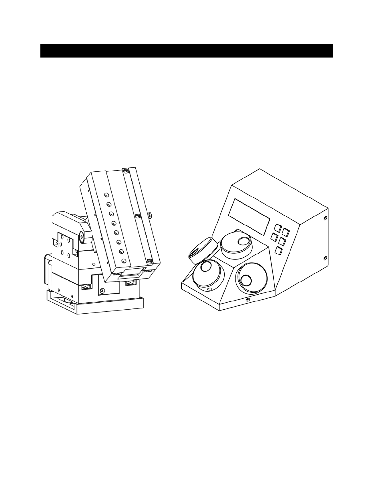
The TRIO MP-235 3-Axis Micromanipulator System is comprised of a ROE/controller, a
power adapter, and a TRIO MP-235/M stepper-motor-based electromechanical
micromanipulator. This manual consists of four parts: This chapter, Introduction, which
provides an overview and general description of the TRIO MP-235 system; Chapter 2,
Installation, which describes how to install, set up, and configure all components of the
system; Chapter 3, Operations, which describes how to operate the TRIO MP-235; Chapter 4,
Maintenance, describes how to perform routine and other maintenance of the TRIO MP-235;
and Chapter 5, Reconfiguration, describes the reconfiguration possibilities of the TRIO MP235 system.
TRIO MP-235/M
ELECTROMECHANICAL
MICROMANIPULATOR
Figure 1-1. The TRIO MP-235 system
TRIO MP-235/E
ROE/CONTROLLER
1.2 Components of the TRIO MP-235 System
Carefully remove all components from the shipping container. In addition to this manual, the
following should be included:
TRIO MP-235 ROE Rotary Optical Encoder input device with built-in controller and
external power adapter.
TRIO MP-235/M electromechanical micromanipulator
TRIO MP-235 THREE-AXIS MICROMANIPULATOR SYSTEM OPERATION MANUAL – REV. 2.23 (20190130) (FW V2.2 & 2.3)
Page 12

10
25-pin DSUB cable (connects the ROE/controller to the TRIO MP-235/M
electromechanical micromanipulator).
Power adapter
Power adapter AC mains cable appropriate for your location
Ground/Earth cable
USB Cable
IMPORTANT
Once the TRIO MP-235 system has been unpacked, remove the shipping tape from the
various locations on the TRIO MP-235/M electromechanical micromanipulator. The shipping
tape must be removed before operating the TRIO MP-235 system. In the event that you need
to transport the TRIO MP-235/M in the future, reapply 2 to 3-inch pieces of masking tape to
the same locations. Once the tape has been removed, handle the TRIO MP-235/M with care.
The mechanisms can be damaged if any of the axes are inadvertently moved without the tape
in place.
1.3 Overview
1.3.1 Features
Three independent axes – 50mm travel in the diagonal axis for coaxial pipette movement,
and 25mm travel in X and Y axes. Travel for the virtual Z axis utilizes a cosine function of
the angle chosen, using the X and D axes.
Sub-micron 100nm resolution
Digital display indicates coordinates in relative or absolute
User-friendly, fanless compact controller with ROE preserves bench space
Push button control of multiple functions – work, home, Lock, pulse and relative
Robotic home and work position moves for easy automated pipette exchange
1.3.2 Description While the a
Sutter has introduced a diagonal axis with the TRIO MP-235 so one can move the electrode
coaxially at the exact desired angle of approach. This axis also significantly extends the range
of travel (50mm) for the system.
The TRIO MP-235’s ROE provides fine control of electrode position and the rate of rotation
of ROE dials for each axis determines the speed of travel. The finest step size is less than
100nm. Five conveniently located buttons on the ROE provide control of all the basic
functions you will need in normal operation (Work, Home, Lock, Relative, and Pulse).
xes provide X and Y orthogonal motion typical of most motorized manipulators,
Press and hold WORK (for 3 seconds) to quickly store a work position, tap HOME to move all
axes to an initial location that is useful for changing electrodes, or press and hold the HOME
button (for 3 seconds) to memorize a new HOME position.
When you are ready to record data, the motor drive electronics can be suppressed by pressing
the LOCK button. In the LOCK mode, the display turns red and ROE input is locked out to
avoid any accidental motion.
TRIO MP-235 THREE-AXIS MICROMANIPULATOR SYSTEM OPERATION MANUAL – REV. 2.23 (20190130) (FW V2.2 & 2.3)
Page 13
11
Pressing and holding the RELATIVE button for three seconds at any location causes the
display coordinates to all zeroes. When activating relative mode, the display turns blue. To
return to viewing the absolute coordinates, tap the RELATIVE button to toggle back.
Finally, tapping the PULSE button causes a 3μm advance in the diagonal. This rapid burst of
forward motion can assist in sharp electrode cell penetration.
All the electronics, except for a small power supply, are housed within the TRIO MP-235 ROE
and no separate controller or computer is required.
External computer control of the TRIO MP-235 is possible via the USB connector mounted
on the controller/ROE’s rear panel. The controller’s internal software is programmed with a
defined set of commands allowing for a wide range of micromanipulator/stage movements as
programmed in software residing in an external computer connected via USB.
2. INSTALLATION
When installing the TRIO MP-235 system for the first time, it is recommended that the
components of the system be installed in the following order: TRIO MP-235/M
electromechanical micromanipulator first, followed by the TRIO MP-235/E ROE/Controller.
2.1 Mounting Instructions
The following sections describe how to mount the TRIO MP-235/M manipulator to a stand
using the mounting adapter plate, how to adjust the pipette angle and how to mount
different headstages.
2.1.1 Mounting the TRIO MP-235/M to th
The TRIO MP-235/M attaches to the mounting adapter plate using four M3.5x6 hex head
locking screws.
Figure 2-1. Side view of TRIO MP-235/M showing mounting adapter plate and lock screws.
e Stand or Platform
Locking Screws Locking Screws
The TRIO MP-235/M is shipped with the adapter plate in place. It is attached using four
tapered pegs, along with four locking screws.
TRIO MP-235 THREE-AXIS MICROMANIPULATOR SYSTEM OPERATION MANUAL – REV. 2.23 (20190130) (FW V2.2 & 2.3)
Page 14

12
To remove it, first loosen the four hex screws that secure the manipulator to the pegs in the
adapter plate. The rear pair is in a similar location in the back of the manipulator. Once the
locking screws are sufficiently loosened, lift the TRIO MP-235/M upwards from the adapter
plate.
Before attaching the adapter plate to the TRIO MP-235/M, you need to decide where to
position the manipulator on your stand/platform. The stand can be any flat surface carrying
¼-20, 10-32, or M6 holes on one-inch centers (such as a Sutter Instrument MT-series stand
or MD series platform).
Examine the space of the platform onto which installation is to take place. Attach the control
cable to TRIO MP-235/M and move the entire unit around on the platform until the precise
desired position is determined. A small bag containing the necessary hardware to attach the
TRIO MP-235 to the stand is included.
Figure 2-2. Mounting the TRIO MP-235/M on the Adapter Plate
Once the plate is mounted, align the pegs on top of the plate with the holes in the
manipulator, push the X-axis firmly onto the plate, and re-tighten the locking hex set
screws.
2.2 Headstage Mounting
Sutter IPA headstage, Axon headstages 203B or CV-7, and the Heka EPC-10 headstage have
an integral dovetail that fits directly into the rotary dovetail slide bracket on the TRIO MP235/M. The dovetail slide bracket on the TRIO MP-235/M also supports older Axon and Heka
headstages when using the 4’’ dovetail extension.
Rod-mounted headstages and micro tools are accommodated by the use of a rod clamp that
fits into the dovetail (not shown). All the headstage adapters and mounting hardware are
included with the manipulator and are shipped in a zip lock plastic bag.
2.3 Other Accessories
One or more accessories may have been ordered and received for mounting the TRIO MP235/M and/or modifying the headstage mount to the manipulator (i.e., rotating base,
microscope stage mount, gantry, dovetail extension, etc.). Setup of these accessories is
normally covered in documentation accompanying the accessory.
TRIO MP-235 THREE-AXIS MICROMANIPULATOR SYSTEM OPERATION MANUAL – REV. 2.23 (20190130) (FW V2.2 & 2.3)
Page 15

13
2.4 Electrical Connections and Initial Operating Instructions
Initially, you may want to simply connect the TRIO MP-235/M micromanipulator and the
ROE/Controller together and try some gross movements in order to get a feel for the controls
and how to make simple movements. It is perfectly acceptable to set the manipulators in the
middle of a bench top, make all electrical connections and then observe each unit’s
movement by eye.
CAUTION: Unless the TRIO MP-235/M micromanipulator electromechanical baseplate
is firmly bolted down to a breadboard or solidly to a firm surface, the TRIO MP-235/M is
likely to tip over when fully extending all of its axes, especially if its loaded with a headstage
that extends beyond the TRIO MP-235/M’s current center of gravity.
Upon deciding to directly install the TRIO MP-235 system in your rig, it is useful to follow
the initial setup procedure to learn how to move the units to allow easy access to the
mounting screws.
1. With the power switch on the back of the ROE in the OFF (0) position, connect the power
adapter’s 24VDC cable to the POWER receptacle.
Figure 2-3. Rear of TRIO MP-235 ROE/Controller cabinet
2. With the power OFF (rear panel switch in the “0” position), connect a wellgrounded/earthed wire to the GROUND banana plug receptacle.
3. With the power OFF, connect the male end of the DB-HD-26 cable to the
MANIPULATOR connector on the ROE, the other end of which is connected to the TRIO
MP-235/M micromanipulator electromechanical. (See cautionary note below.)
4. Verify that the ten switches on the rear of the ROE are set as desired.
5. Power up the system by moving the power switch on the rear of the ROE to the “1”
position.
TRIO MP-235 THREE-AXIS MICROMANIPULATOR SYSTEM OPERATION MANUAL – REV. 2.23 (20190130) (FW V2.2 & 2.3)
Page 16

14
* CAUTION: NEVER CONNECT OR DISCONNECT THE ROE/CONTROLLER
FROM THE TRIO MP-235/M WHILE THE POWER IS ON!
2.5 ROE/Controller Rear Panel Controls and Configuration
2.5.1 Power Switch
The power switch for the TRIO MP-235 system is located on the rear panel of the
ROE/controller. At power up, the microprocessor in the ROE/controller scans the attached
equipment and configures the system accordingly.
2.5.2 Configuration Switches
1 2 3 4 5 6 7 8 9 10
Figure 2-4. Configuration switches on rear of TRIO MP-235 ROE/Controller unit (switch positions shown are
factory defaults).
2.5.2.1 Switches 1, 2, 3, and 4
The first four switches set the directionality for each of the four axis-movement knobs.
Table 2-1. Configuring the directionality of each axis-movement knob.
Switch # Axis
1 X OFF (Up)* ON (Down)
2 Y OFF (Up)* ON (Down)
3 Z OFF (Up)* ON (Down)
4 D OFF (Up)* ON (Down)
Knob Rotation Directionality for Forward (+) Movement
Clockwise Counterclockwise
* Factory default (typical setting for right-hand-mounted manipulator).
2.5.2.2 Switch 5: Locking Out Y Movement During Homing
Configures whether the Y axis is locked out while homing.
Table 2-2. Configuring the Homing Y-Movement Lock Out.
Homing Y Movement Lock Out Switch #
Enabled Disabled
5 OFF (Up) ON (Down)*
* Factory default (recommended normal operation setting).
TRIO MP-235 THREE-AXIS MICROMANIPULATOR SYSTEM OPERATION MANUAL – REV. 2.23 (20190130) (FW V2.2 & 2.3)
Page 17

2.5.2.3 Switch 6: Sensor Test (Firmware < v2.2)
Table 2-3. Configuring the Sensor Test.
Sensor Test Switch #
Enabled ** Disabled
6 OFF (Up) ON (Down)*
* Factory default (do not change unless requested to by Sutter Instrument Technical
Support).
** CAUTION: To avoid damage to the micromanipulator or stage, DIP Switch 6 (Sensor
Test) must always be set to OFF (DOWN).
15
2.5.2.4
Switch 6: Calibration Homing on Power On (Firmware v2.2+)
Configures whether calibration homing occurs or not on power on (FW v2.2+).
Table 2-4. Calibration Homing on Power On (Firmware v2.2+).
Calibration Homing on Power On Switch #
None (No calibration) Calibration occurs
6 OFF (Up) ON (Down)*
* Factory default (recommended normal operation setting).
2.5.2.5 Switches 7 through 10
These four switches are reserved for all controllers programmed with a firmware version
below v2.2. For firmware v2.2 and above, the switches are defined in the following
paragraphs.
2.5.2.6 Switch 7: Speed of Manual Movement (Firmware v2.2+)
This switch determines the speed at which movement takes place when manipulated by the
ROE rotational knobs for any axis. The OFF (up) position configures the speed to “normal”
(factory default). Set the switch to ON (down) for slower speed in situations where the
micromanipulator or stage is burdened with heavier loads. This speed setting affects only
manual movement using the rotation knobs of the ROE; moves initiated by external
command (see Chapter 4) are not affected.
Table 2-5. Speed of manual movement (Firmware v2.2+).
Speed of Manual Movement Switch #
Normal Slower**
7 OFF (Up)* ON (Down)
* Factory default (recommended normal operation setting).
** Use the ON (down) setting for slower speed when the micromanipulator or stage is
burdened with heavier loads.
TRIO MP-235 THREE-AXIS MICROMANIPULATOR SYSTEM OPERATION MANUAL – REV. 2.23 (20190130) (FW V2.2 & 2.3)
Page 18

16
2.5.2.7 Switch 8: Reserved (Firmware <= v2.2)
This switch is reserved for future use. The factory default position is OFF (up).
2.5.2.8 Switch 8: ROE Axis Movement Knobs Active – All vs. D Only (Firmware v2.3+)
This switch determines if all axis-movement knobs of the ROE are active or only the D-axis
knob.
Table 2-6. ROE Axis movement knobs active – all vs. D only ( (Firmware v2.3+).
ROE Axis Movement Knobs Active – All vs. D Only Switch #
All Active (X, Y, Z, & D) D Only (X, Y, & Z inactive)**
8 OFF (Up)* ON (Down)
* Factory default (recommended normal operation setting).
** Use the ON (down) setting for when it is desired to have only the D-axis movement knob
active, while the rest (X, Y, & Z) are inactive.
2.5.2.9 Switch 9: Y-Axis Travel Length (Firmware v2.2+)
This switch informs the ROE/controller as to the travel length of the Y axis in the connected
micromanipulator eletromechanical or stage. The length of the Y axis on the TRIO MP-235/M
electromechanical micromanipulator is 25mm, so Switch 9 should be set to OFF (up) (factory
default for a standard TRIO MP-235 system). For a variant model with 12.5mm of travel in
the Y axis, Switch 9 must be set ON (down).
Table 2-7. Y-Axis travel length (Firmware v2.2+).
Y-Axis Travel Length Switch #
25mm 12.5mm **
9 OFF (Up)* ON (Down)
* Factory default (recommended normal operation setting).
** Use the ON (down) setting for half-length Y axis (12.5mm).
CAUTION: Always be certain that the position of Switch 9 correctly matches the physical
length of travel of the Y axis on the connected device. Setting the switch to the OFF (up)
position for 25mm could result in equipment damage if the attached device’s Y axis length of
travel is actually less than 25mm.
2.5.2.10
Switch 10: X Axis Travel Length (Firmware v2.2+)
This switch informs the ROE/controller as to the travel length of the X axis in the connected
micromanipulator eletromechanical or stage. The length of the X axis on the TRIO MP235/M electromechanical micromanipulator is 25mm, so Switch 10 should be set to OFF (up)
(factory default for a standard TRIO MP-235 system). For a variant model with 12.5mm of
travel in the X axis, Switch 10 must be set ON (down).
TRIO MP-235 THREE-AXIS MICROMANIPULATOR SYSTEM OPERATION MANUAL – REV. 2.23 (20190130) (FW V2.2 & 2.3)
Page 19

17
Y
Table 2-8. Length of X Axis (Firmware v2.2+).
Length of X Axis Switch #
25mm 12.5mm **
10 OFF (Up)* ON (Down)
* Factory default (recommended normal operation setting).
** Use the ON (down) setting for half-length (12.5mm) X axis.
CAUTION: Always be certain that the position of Switch 10 correctly matches the physical
length of travel of the X axis on the connected device. Setting the switch to the OFF (up)
position for 25mm could result in equipment damage if the attached device’s X axis length of
travel is actually less than 25mm.
3. OPERATIONS
3.1 Main Controls and Indicators on the ROE/Controller
DISPLAY
Z-AXIS
CONTROL
(Synthetic)
-AXIS
CONTROL
Figure 3-1. Front view of the TRIO MP-235 ROE/Controller
HOME
POSITION
WORK
POSITION
PULSE &
ANGLE-SET
MODES
RELATIVE
MODE
SPEED &
LOCK
MODES
D-AXIS
CONTROL
X-AXIS
CONTROL
TRIO MP-235 THREE-AXIS MICROMANIPULATOR SYSTEM OPERATION MANUAL – REV. 2.23 (20190130) (FW V2.2 & 2.3)
Page 20

18
S
T
-23
5
R
2
0
3.2 Display
3.2.1 Initial Startup
Figure 3-1. LCD Display showing startup screen.
When starting the TRIO MP-235 system for the first time or if the HOME position has not
yet been defined (saved), the values of all four axes will be 1,000 micrometers (microns).
INSTRUMENT CORP.
RIO / MP
UTTER
EV 2.
(Text in
Green)
(Text in
Green)
Figure 3-2. Startup screen
X= 1000 Y= 1000
D= 1000 >=
Figure 3-3. Factory default startup (Home) position
(Text in
Green)
3.3 Control Operations
3.3.1 Maximum Positive Position Values:
Move the dial of an axis clockwise until its position value stops incrementing. The following
table lists the maximum position value (in microns) for each axis.
Table 3-1. Maximum positive position value of each axis
Axis Maximum Position
Value (in microns)
X 25,000
Y 25,000
D 50,000
X=25000 Y=25000
D=50
Figure 3-4. Maximum positive values
00 >=
(Text in
Green)
3.3.2 Setting Position for HOME or WORK
To set position, hold down HOME or WORK button for 3 seconds until beep sounds.
TRIO MP-235 THREE-AXIS MICROMANIPULATOR SYSTEM OPERATION MANUAL – REV. 2.23 (20190130) (FW V2.2 & 2.3)
Page 21

19
3.3.3 Setting the Angle of the Pipette/Headstage Holder
To change the angle of the holder, first loosen the set screw at the top of the rotary dovetail
bracket, rotate the holder to the desired angle, and then retighten the set screw.
Measure the angle of the holder. (Tip: Many smart phones have an app with a level that can
assist the user.)
3.3.4 Operating the Virtual Z Axis
The TRIO
and D axes and the angle of the holder has been implemented to create a virtual Z-axis. Best
results are obtained when using it between 10° and 90°.
Zero (0°) is set with the diagonal being parallel to the table and 90° is set with the diagonal
being perpendicular to the table.
To set the angle measured above, on the ROE hold PULSE down for 3 seconds. The screen
will be red until the display indicates in green: “Select the angle in use (0-90)”.
Use the D dial on the ROE to set the value of the angle. Once this value is dialed in, do not
touch the ROE knob for 8-10 sec. The virtual D angle will now be set.
3.3.5 Moving to the Home Position (HOME)
MP-235 consists of three physical axes, X, Y and D. A cosine function utilizing X
X= 0 Y= 1524
=
Figure 3-5. Moving to Home position (screen is amber while moving)
=
(Text in
Red)
If the Home position has not yet been defined and saved, the Home position values for all
axes will default to 1,000 microns, as shown in the following figure.
If the Home position has been previously defined (saved), pressing HOME will make a move
to the defined home position (see example in the following figure).
Figure 3-7. Example Home position defined and saved
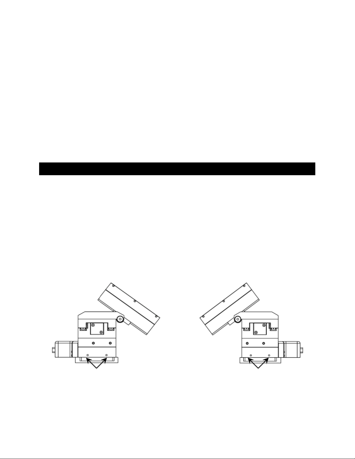
To move to the Home position, press HOME. If the current position before pressing HOME is
greater than the Home position, the movement will be as follows:
NOTE: Movement to the Home position works only if X coordinates of the HOME position
are less than the WORK position.
1. Movement begins by retracting the D axis (at the angle currently set) away from the
sample.
X= 1000 Y= 1000
D= 1000 >=
Figure 3-6. Factory default Home position
X=1868 Y=1524
D=1686 >=25
(Text in
Green)
(Text in
Green)
TRIO MP-235 THREE-AXIS MICROMANIPULATOR SYSTEM OPERATION MANUAL – REV. 2.23 (20190130) (FW V2.2 & 2.3)
Page 22

20
2. Movement then continues along the X axis toward the Home position.
3. The final movement is along the Y-axis towards the operator and away from the
microscope.
NOTE: Step 3 occurs only if “Y-Lockout” is disabled. Otherwise, no movement along the Yaxis occurs.
3.3.6 Moving to the Work Position (WORK)
X=2868 Y=2524
D=1686 >=25
(Text in
Green)
Figure 3-8. Example Work position
To move to the Work position, press the WORK button. If the current position before
pressing WORK is less than the Work position, the movement will be as follows:
1. Movement travels along the Y-axis away from the operator and towards the microscope.
2. Movement is then made along the X axis toward the sample.
3. Travel then continues along the diagonal until reaching its end-of-travel point.
NOTE: Step 1 occurs only if “Y-Lockout” is disabled. Otherwise, movement begins with
Step 2.
3.3.7 Setting Absolute/Relative Coordinates Mode (RELATIVE)
The REL
ATIVE button toggles between Relative and Absolute coordinate systems. The
default coordinate system on power up is Absolute, with the coordinates on the screen shown
in green. To switch to relative coordinates, press the RELATIVE button once. To reset the
current position to all zeroes, depress the RELATIVE for 3 seconds or until a beep is heard,
and then release the button. This resets the current position to all zeroes.
Press RELATIVE once (briefly for < 2 sec.)
X=-893 Y= 1524
D= 1686 >= 30
Figure 3-9. Relative mode
(Text in
Blue)
Depress RELATIVE for 3 sec. or until beep sounds
X=- 0 Y= 0
D= 0 >= 0
Figure 3-10. Relative mode
(Text in
Blue)
Pressing RELATIVE briefly while in Relative mode, returns displayed coordinates back to
Absolute mode
TRIO MP-235 THREE-AXIS MICROMANIPULATOR SYSTEM OPERATION MANUAL – REV. 2.23 (20190130) (FW V2.2 & 2.3)
Page 23

21
X=-
D
=
X
X
3.3.8 Mode Indications The TRIO MP-235 system has three modes of operation: Absolute coordinates, Relative
coordinates, and Lock mode. The display turns color for each specific mode, as shown in the
following table.
Screen Color Mode Example
X=-893 Y= 1524
D= 1686 >= 30
Figure 3-11. Absolute mode
Table 3-2. Screen colors and modes
(Text in
Green)
Green Absolute Coordinates
Blue Relative Coordinates
Red Knobs disabled during move to
Home or Work position, while in
Lock mode.
3.3.9 Speed Control and ROE Knob Movements (SPEED) The rate at which the ROE axis knobs move the electromechanical can be adjusted with the
SPEED button. Each press of the button cycles through four speeds: 0 (normal) through 3
(fastest).
3.3.10 Movement Knobs Disabling and Lock Mode ([SPEED]/
Axis-movement knobs are disabled during movements to Home, Work, or while in Lock Mode
(display is in red).
3.3.11 Pausing Home Movements (HOME (while moving to Home))
fter Move to Home has been initiated, and while the move is in progress, pressing HOME a
A
second time pauses the manipulator. Pressing HOME again resumes movement.
= 1868 Y= 1524
D= 1686 >= 27
0 Y= 0
0 >= 0
= 0 Y= 1524
D= 0 >= 0
LOCK)
3.3.12 Pausing Work Movements (WORK (while moving to Work))
fter Move to Work has been initiated, and while the move is in progress, pressing WORK a
A
second time pauses the manipulator. Pressing WORK again resumes movement.
3.3.13 Pulse Mode and D-Axis Movement (PULSE) Pulse
increments the Diagonal axis by one 2.85-μm step beyond the current position. This feature
can be used to penetrate tough or resistant tissue.
mode advances the D axis in 2.85 μm steps. Each press of the PULSE button
TRIO MP-235 THREE-AXIS MICROMANIPULATOR SYSTEM OPERATION MANUAL – REV. 2.23 (20190130) (FW V2.2 & 2.3)
Page 24

22
4. EXTERNAL CONTROL
4.1 General
Controlling the TRIO MP-235 externally via computer is accomplished by sending commands over the
USB interface between the computer and the USB connector on the rear panel of the TRIO MP-235
controller/ROE. The USB device driver for Windows is downloadable from Sutter Instrument’s web
site (www.sutter.com
2.10.00 or higher. The CDM device driver for the TRIO MP-235 consists of two device drivers: 1) USB
device driver, and 2) VCP (Virtual COM Port) device driver. Install the USB device driver first,
followed by the VCP device driver. The VCP device driver provides a serial RS-232 I/O interface
between a Windows application and the TRIO MP-235. Although the VCP device driver is optional, its
installation is recommended even if it is not going to be used. Once installed, the VCP can be enabled
or disabled.
The CDM device driver package provides two I/O methodologies over which communications with the
controller over USB can be conducted: 1) USB Direct (D2XX mode), or 2) Serial RS-232 asynchronous
via the VCP device driver (VCP mode). The first method requires that the VCP device driver not be
installed, or if installed, that it be disabled. The second method requires that the VCP be installed and
enabled.
). The TRIO MP-235 requires USB CDM (Combined Driver Model) Version
4.2 Virtual COM Port (VCP) Serial Port Settings
The following table lists the required RS-232 serial settings for the COM port (COM3, COM5, etc.)
generated by the installation or enabling of the VCP device driver.
Table 4-1. USB-VCP interface serial port settings.
Property Setting
Data (“Baud”) Rate (bits per second (bps))
Data Bits 8
Stop Bits 1
Parity None
Flow Control None
57600
The settings shown in the above table can be set in the device driver’s properties (via the Device
Manager if in Windows) and/or programmatically in your application.
4.3 Protocol and Handshaking
Command sequences do not have terminators. All commands return an ASCII CR (Carriage Return;
13 decimal, 0D hexadecimal) to indicate that the task associated with the command has completed.
When the controller completes the task associated with a command, it sends ASCII CR back to the
host computer indicating that it is ready to receive a new command. If a command returns data, the
last byte returned is the task-completed indicator.
4.4 Command Sequence Formatting
attingEach command sequence consists of at least one byte, the first of which is the “command byte”.
Those commands that have parameters or arguments require a sequence of bytes that follow the
command byte. No delimiters are used between command sequence arguments, and command
sequence terminators are not used. Although most command bytes can be expressed as ASCII
displayable/printable characters, the rest of a command sequence must generally be expressed as a
sequence of unsigned byte values (0-255 decimal; 00 – FF hexadecimal, or 00000000 – 11111111
TRIO MP-235 THREE-AXIS MICROMANIPULATOR SYSTEM OPERATION MANUAL – REV. 2.23 (20190130) (FW V2.2 & 2.3)
 Loading...