

Page 1

OPERATION MANUAL
P
P----97
PP
Flaming/Brown
Flaming/Brown
Flaming/BrownFlaming/Brown
Micropipette
Micropipette
MicropipetteMicropipette
Puller
Puller
PullerPuller
Rev. 2.03 – DOM (20091301)
97
9797
Page 2

Page 3
P
P----97
PP
Flaming/Brown Micropipette Puller
Flaming/Brown Micropipette Puller
Flaming/Brown Micropipette PullerFlaming/Brown Micropipette Puller
97
9797
Operation Manual
(Rev. 2.03 – DOM (20091301))
Sutter Instrument Company
One Digital Drive
Novato, CA 94949
Voice: 415-883-0128 Web: www.sutter.com
Fax: 415-883-0572 Email: info@sutter.com
Page 4

Copyright © 2009 Sutter Instrument Company. All Rights Reserved.
P-97 FLAMING/BROWN MICROPIPETTE PULLER OPERATION MANUAL – REV. 2.03 – DOM (20091301)
Page 5

TABLE OF CONTENTS
TABLE OF CONTENTS
TABLE OF CONTENTSTABLE OF CONTENTS
1. GENERAL INFORMATI
1. GENERAL INFORMATION
1. GENERAL INFORMATI1. GENERAL INFORMATI
1.1 T
ECHNICAL SUPPORT
1.2 W
HAT’S NEW ON THE
2. SAFETY WARNINGS A
2. SAFETY WARNINGS AND PRECAUTI
2. SAFETY WARNINGS A2. SAFETY WARNINGS A
2.1 M
AIN FUSE
2.2 A
VOIDING ELECTRICAL SHOCK OR FIRE INJURY
2.3 B
ACK INJURY PREVENTION
3. PRECAUTIONS
3. PRECAUTIONS ................................
3. PRECAUTIONS3. PRECAUTIONS
3.1 P
RECAUTIONS DURING OPERATION
3.2 ON H
4. GLASS CAPILLARY &
4. GLASS CAPILLARY & HEATING FILAMENT SP
4. GLASS CAPILLARY &4. GLASS CAPILLARY &
4.1 G
LASS CAPILLARY
4.2 H
EATING FILAMENT
.........................................................................................................................................3
................................................................
................................................................
ANDLING MICROPIPETTES
ON ................................
................................................................
ONON
................................................................
................................................................
................................................................
........................................................................................................................1
P-97?..............................................................................................................1
ND PRECAUTIONS
ND PRECAUTIND PRECAUTI
ONS................................
................................................................
ONSONS
................................................................
.............................................................................3
..............................................................................................................3
................................................................
................................................................
.................................................................................................5
.......................................................................................................5
HEATING FILAMENT SPECIFICATIONS
HEATING FILAMENT SP HEATING FILAMENT SP
..............................................................................................................................7
..........................................................................................................................7
...........................................
................................................................
................................................
................................................................
...............................................................
................................................................
ECIFICATIONS................................
ECIFICATIONSECIFICATIONS
..........................................
................................................................
...............................5555
..............................................................
................3333
................................
...........1111
......................
..........7777
....................
5. UNPACKING
5. UNPACKING................................
5. UNPACKING5. UNPACKING
6. SETTING UP
6. SETTING UP................................
6. SETTING UP6. SETTING UP
6.1 L
INE POWER (MAINS
7. FRONT PANEL
7. FRONT PANEL................................
7. FRONT PANEL7. FRONT PANEL
7.1 C
ONTROLS
7.2 D
ISPLAY
8. MECHANICAL DESCRI
8. MECHANICAL DESCRIPTION (PULLER ANATOM
8. MECHANICAL DESCRI8. MECHANICAL DESCRI
8.1 S
OME BASIC INFORMATION
8.2 A
IR COOLING SYSTEM
8.3 H
EATING ASSEMBLY
8.4 U
PPER PULLEY ASSEMBLY
8.5 C
ABINET
8.6 E
LECTRONICS
9. FIRST TIM
9. FIRST TIME USE
9. FIRST TIM9. FIRST TIM
10. PROGRAMS
10. PROGRAMS................................
10. PROGRAMS10. PROGRAMS
10.1 P
10.2 P
10.3 P
10.4 D
10.5 S
10.6 V
10.7 C
10.8 E
ROGRAM STRUCTURE
ROGRAM LINE PULL CYCLE PARAMETERS
ULL CYCLE
EFAULT CONFIGURATION
ELECTING A PROGRAM
IEWING A PROGRAM
LEARING A PROGRAM FROM MEMORY
DITING A PROGRAM
................................................................
................................................................
................................................................
................................................................
................................................................
................................................................
................................................................
................................................................
................................................................
................................................................
................................................................
................................................................
....................................
................................................................
..................................
................................................................
)......................................................................................................................11
................................................................
................................................................
................................................................
................................................................
..............................................................
................................................................
..............................13
............................................................
........................................................................................................................................13
............................................................................................................................................14
PTION (PULLER ANATOMY)
PTION (PULLER ANATOMPTION (PULLER ANATOM
Y)................................
............................................................
Y)Y)
................................................................
............................17
........................................................
.............................................................................................................17
.....................................................................................................................17
........................................................................................................................18
..............................................................................................................20
...........................................................................................................................................21
...................................................................................................................................21
E USE ................................
E USEE USE
................................................................
................................................................
................................................................
................................................................
................................................................
................................................................
................................................................
................................................................
..........................................................
................................................................
................................................................
................................................................
..........................23
....................................................
..................................
................................................................
..................................................................................................................25
................................................................................25
...................................................................................................................................26
...........................................................................................................27
................................................................................................................27
....................................................................................................................28
.......................................................................................28
.....................................................................................................................28
10.8.1 Entering a New Program......................................................................................................28
10.8.2 Editing an Existing Program................................................................................................29
....9999
........
..11
11
....
1111
13
1313
17
1717
23
2323
..25
25
....
2525
P-97 FLAMING/BROWN MICROPIPETTE PULLER OPERATION MANUAL – REV. 2.03 – DOM (20091301)
Page 6

11. SOFTWARE CONTROL
11. SOFTWARE CONTROL FUNCTIONS
11. SOFTWARE CONTROL11. SOFTWARE CONTROL
11.1 RAMP TEST < 1 >......................................................................................................................31
11.2 CHANGE AIR PRESSURE < 2 >.............................................................................................32
11.3 AIR MODE < 3 >.........................................................................................................................33
11.4 AIR TIME AT START OF PULL < 4 > ...................................................................................33
11.5 AIR TIME AT END OF PULL < 5 >........................................................................................34
11.6 RESET TIME AND DATE < 6 > ..............................................................................................34
11.7 WRITE-PROTECT THE PROGRAM < 7 >............................................................................34
11.8 MEMORY TEST < 8 >...............................................................................................................34
12. PULLING PIPETTES
12. PULLING PIPETTES................................
12. PULLING PIPETTES12. PULLING PIPETTES
12.1 P
12.2 N
13. PARAMETER ADJUST
13. PARAMETER ADJUSTMENT
13. PARAMETER ADJUST13. PARAMETER ADJUST
13.1 G
13.2 M
13.3 P
13.4 S
13.5 T
13.6 F
ROCEDURES
OTES ON PROGRAM OPERATION
ENERAL INFORMATION
ICROPIPETTE/MICROINJECTION NEEDLE FABRICATION
13.2.1 HEAT ......................................................................................................................................37
13.2.2 PULL Strength.......................................................................................................................37
13.2.3 VELOCITY (Trip Point)........................................................................................................38
13.2.4 TIME Mode (Cooling)............................................................................................................38
13.2.5 Delay Mode (Cooling).............................................................................................................38
13.2.6 PRESSURE Adjustment.......................................................................................................39
13.2.7 Filament Width ......................................................................................................................39
ATCH PIPETTE FABRICATION
13.3.1 HEAT ......................................................................................................................................40
13.3.2 PULL Strength.......................................................................................................................40
13.3.3 VELOCITY (Trip Point)........................................................................................................40
13.3.4 TIME Mode (Cooling)............................................................................................................41
13.3.5 PRESSURE ............................................................................................................................41
TEP-BY-STEP PATCH PIPETTE PROGRAMMING
ECHNICAL TIPS FOR PULLING MICROPIPETTES
13.5.1 Regulating the Time it takes to pull a Sharp Pipette ........................................................43
13.5.1.1 Pipette Position..........................................................................................................................................................43
13.5.2 Regulating the Length and Tip Size of a Sharp Pipette....................................................43
13.5.2.1 Filament Width..........................................................................................................................................................43
13.5.2.2 Air Flow.......................................................................................................................................................................43
13.5.2.3 DELAY Mode of Active Cooling..............................................................................................................................44
IRE POLISHING
..................................................................................................................................35
FUNCTIONS................................
FUNCTIONS FUNCTIONS
................................................................
................................................................
MENT ................................
MENTMENT
............................................................................................................................44
................................................................
................................................................
...............................................................................................................37
.....................................................................................................40
................................................................
................................................................
................................................................
................................................................
................................................................................................36
................................................................
................................................................
.........................................................................41
.......................................................................43
......................................................
................................................................
..................................................
................................................................
...................................
................................................................
.........................................................37
......................31
............................................
..................35
....................................
31
3131
35
3535
...37
37
......
3737
14. HEATING FILAMENT
14. HEATING FILAMENTSSSS ................................
14. HEATING FILAMENT14. HEATING FILAMENT
14.1 G
14.2 T
14.3 B
15. MAINTENANCE
15. MAINTENANCE................................
15. MAINTENANCE15. MAINTENANCE
ENERAL INFORMATION
ROUGH FILAMENT
14.2.1 Positioning..............................................................................................................................47
14.2.2 Geometry.................................................................................................................................47
OX FILAMENT
14.3.1 Positioning..............................................................................................................................49
14.3.2 Geometry.................................................................................................................................49
P-97 FLAMING/BROWN MICROPIPETTE PULLER OPERATION MANUAL – REV. 2.03 – DOM (20091301)
..............................................................................................................................48
................................................................
................................................................
................................................................
................................................................
...............................................................................................................47
.......................................................................................................................47
................................................................
................................................................
................................................................
................................................................
..........................................................
................................................................
.............................................
................................................................
..........................51
....................................................
.............47
..........................
47
4747
51
5151
Page 7

15.1 C
15.2 H
15.3 P
15.4 R
16. TROUBLESHOOTING
16. TROUBLESHOOTING................................
16. TROUBLESHOOTING16. TROUBLESHOOTING
16.1 C
16.2 C
16.3 T
LEANING
EATING FILAMENT REPLACEMENT
15.2.1 Systematic Filament Replacement.......................................................................................51
15.2.2 Air jet Position........................................................................................................................51
15.2.3 Positioning the Filament in Relation to the Glass Capillary ............................................51
ULLEY ADJUSTMENT
EGENERATION OF DRIERITE GRANULES
ONTROLLING PIPETTE TIP SHAPES
16.1.1 Problem: What type of glass should be used?.....................................................................57
16.1.2 Problem: The resistance of pulled pipettes is too low. How can a higher-resistance
pipette be pulled?...............................................................................................................................57
16.1.3 Problem: Okay, but how can tips be made even smaller?.................................................57
16.1.4 Problem: How can the size of a patch-pipette be increased?.............................................58
16.1.5 Problem: Patch-pipette tips vary in size from pull to pull.................................................58
16.1.6 Problem: An injection pipette with a 1mm tip that is 20 to 50mm long needs to be
formed. How can this be done?.......................................................................................................58
16.1.7 Problem: The electrodes are bent. How can they be made to pull straight?..................58
16.1.8 Problem: One electrode is much longer than the other electrode....................................58
16.1.9 Problem: The shape and resistance of the pipette changes from pull to pull..................59
ONTROLLER PROBLEMS
16.2.1 Problem: The filament does not light up when pull is pressed........................................59
16.2.2 Problem: Display blank, fan not on, or locked up/overlap................................................60
16.2.3 Problem: Display shows a row of blocks.............................................................................60
16.2.4 Problem: Displayed program values are not correct.........................................................60
ECHNICAL SUPPORT
.......................................................................................................................................51
...........................................................................................51
...................................................................................................................53
...................................................................................54
................................................................
................................................................
..............................................................................................................59
....................................................................................................................60
................................................................
................................................................
...........................................................................................57
................................................
................................................................
................57
................................
57
5757
APPENDIX A. FUSE REP
APPENDIX A. FUSE REPLACEMENT
APPENDIX A. FUSE REPAPPENDIX A. FUSE REP
APPENDIX B. LIMITED
APPENDIX B. LIMITED WARR
APPENDIX B. LIMITED APPENDIX B. LIMITED
APPENDIX C. DISCLAIM
APPENDIX C. DISCLAIMER
APPENDIX C. DISCLAIMAPPENDIX C. DISCLAIM
APPENDIX D. TECHNICA
APPENDIX D. TECHNICAL SPECIFICATIONS
APPENDIX D. TECHNICAAPPENDIX D. TECHNICA
APPENDIX E. DRIERITE
APPENDIX E. DRIERITE MATERIAL SAFETY DAT
APPENDIX E. DRIERITEAPPENDIX E. DRIERITE
INDEX
INDEX................................
INDEXINDEX
TABLE OF FIGURES
TABLE OF FIGURES
TABLE OF FIGURESTABLE OF FIGURES
Figure 6-1. P-97 Cabinet (rear view)......................................................................................................11
Figure 6-2. P-97 Cabinet (end view, left). ..............................................................................................11
Figure 6-3. Power connection..................................................................................................................11
Figure 7-1. P-97 Front Panel...................................................................................................................13
Figure 7-2. Program Display...................................................................................................................14
Figure 8-1. P-97 Base Plate (Top view, cover removed).......................................................................17
................................................................
................................................................
LACEMENT................................
LACEMENTLACEMENT
WARRANTY
WARRWARR
ANTY................................
ANTYANTY
ER................................
................................................................
ERER
................................................................
L SPECIFICATIONS................................
L SPECIFICATIONSL SPECIFICATIONS
MATERIAL SAFETY DATA SHEET
MATERIAL SAFETY DAT MATERIAL SAFETY DAT
................................................................
................................................................
................................................................
................................................................
................................................................
................................................................
................................................................
................................................................
................................................................
................................................................
................................................................
................................................................
...........................................................
................................................................
............................................................
................................................................
A SHEET................................
A SHEETA SHEET
...........................61
......................................................
............................63
........................................................
............................................
................................................................
...........................................
................................................................
..................................................
................................................................
.................................................
................................................................
............65
........................
...........67
......................
..................69
....................................
.................71
..................................
61
6161
63
6363
65
6565
67
6767
69
6969
71
7171
P-97 FLAMING/BROWN MICROPIPETTE PULLER OPERATION MANUAL – REV. 2.03 – DOM (20091301)
Page 8

Figure 8-2. Filament Block Assembly. ...................................................................................................18
Figure 8-3. Upper cable pulley assembly................................................................................................20
Figure 9-1. Left puller bar. ......................................................................................................................23
Figure 10-1. Power-On Display...............................................................................................................27
Figure 10-2. P-97 Program Display........................................................................................................27
Figure 10-3. Clear Program Display.......................................................................................................28
Figure 11-1. Access to Control Functions..............................................................................................31
Figure 12-1. Pull Cycle Report................................................................................................................35
Figure 12-2. Sample program..................................................................................................................36
Figure 12-3. Pull cycle report (multiple-loops)......................................................................................36
Figure 13-1. Side view of fire polishing spacer. .....................................................................................45
Figure 13-2. Fire Polish Spacer in Puller Bar. ......................................................................................45
Figure 14-1. End view of trough filament and glass.............................................................................47
Figure 14-2. End view of box filament. ..................................................................................................48
Figure 15-1. V-Groove bearings and puller bars...................................................................................51
Figure 15-2. Filament alignment............................................................................................................52
Figure 15-3. Micropipette shapes............................................................................................................53
Figure 15-4. Pulley Adjustment..............................................................................................................54
Figure 16-1. Power entry module. ..........................................................................................................61
Figure 16-2. Fuse holder..........................................................................................................................61
TABLE OF TABLES
TABLE OF TABLES
TABLE OF TABLESTABLE OF TABLES
Table 10-1. Standard Factory Configuration.........................................................................................27
Table 11-1. Control Functions.................................................................................................................31
Table 11-2. Maximum heat and recommended starting values for different filament shapes........32
Table 14-1. Trough filament sizes. .........................................................................................................48
Table 14-2. Box filament sizes.................................................................................................................49
P-97 FLAMING/BROWN MICROPIPETTE PULLER OPERATION MANUAL – REV. 2.03 – DOM (20091301)
Page 9

1
1.
1. G E NERAL I NF ORMATI ON
GEN E RA L INFO RM ATION
1.1 .
GEN E RA L INFO RM ATIONGEN E RA L INFO RM ATION
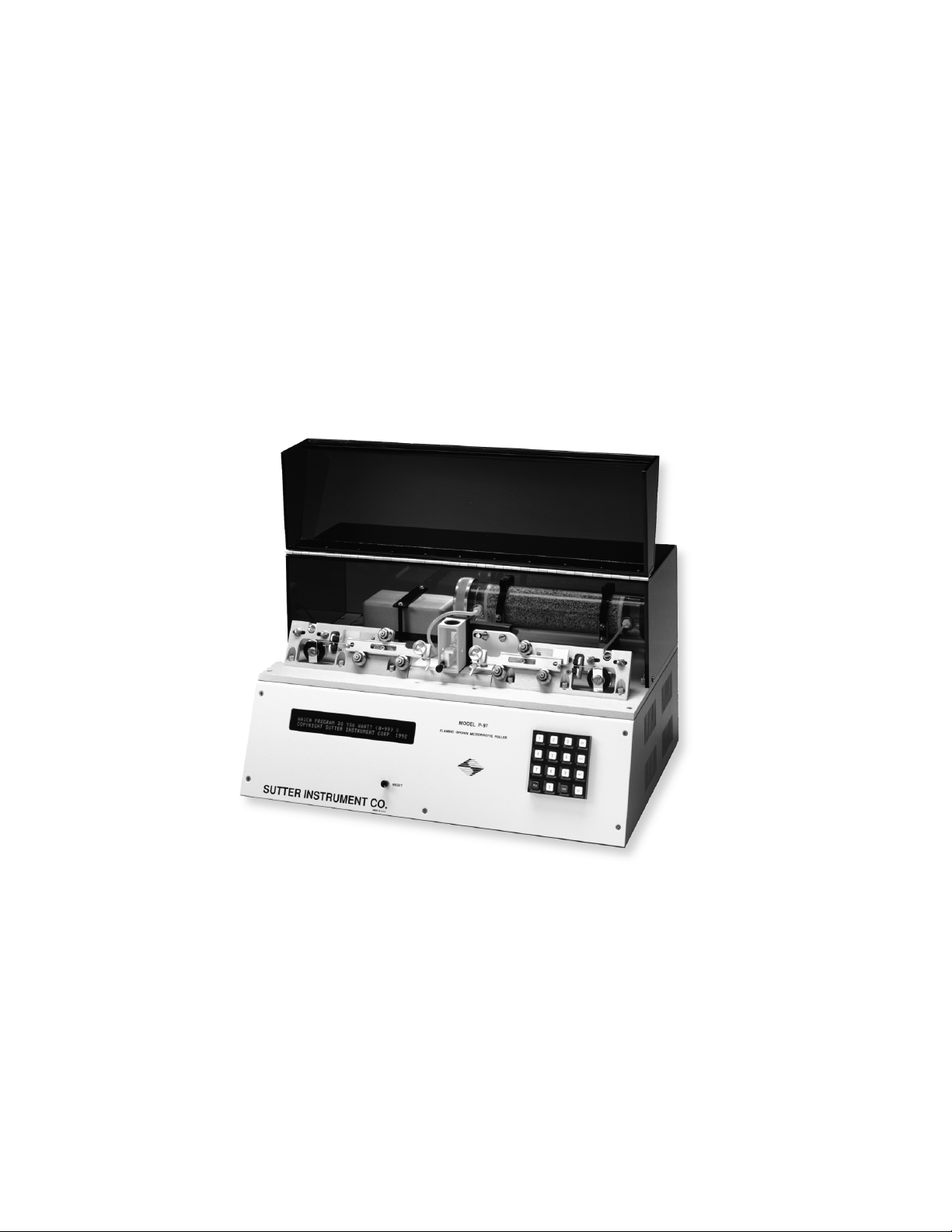
The P-97 can fabricate pipettes for use in intracellular recording, patch clamping,
transferring (ICSI, ES Cells), microinjection, aspiration, and microperfusion. Realizing the
full potential of this instrument is dependent on a complete understanding of the way it
implements the pulling process. To this end, we urge that this manual be read in its entirety.
To aid in understanding the function of the instrument, sample programs are already loaded
in memory (as discussed in subsequent material).
The Model P-97 Flaming/Brown Micropipette Puller combines a proven pulling technology
with programmability to produce a very versatile instrument. The pulling mechanism is
derived from the P-77/P-80 series of pullers, which have demonstrated the ability to pull a
complete range of pipette profiles. Added to this mechanism is the ability to program
different pulling sequences; thus, allowing ease of use for pulling a multiplicity of pipettes on
one device.
The P-97 is a ‘velocity sensing’ puller. This patented feature allows the puller to indirectly
sense the viscosity of the glass, giving the P-97 the ability to pull pipettes from all glasses
except quartz. Even difficult to pull formulations, such as aluminosilicate glasses, are
handled with relative ease.
Throughout this manual reference will be made to the size of the glass tubing used to pull
micropipettes. The convention used here for describing the outside diameter (O.D.) and
inside diameter (I.D.) is as follows: O.D. x I.D. These dimensions will always be given in
millimeters (mm). See our catalog or visit
www.sutter.com
to find a wide selection of glass
capillaries available for purchase.
1.1
1.1 Technical Support
Technical Support
1.11.1
Technical SupportTechnical Support
Unlimited technical support is provided by Sutter Instrument Company at no charge to our
customers. Our technical support staff is available between the hours of 8:00 AM and 5:00
PM (Pacific Standard Time) at (415) 883-0128. You may also Email your queries to
info@sutter.com.
1.2
1.2 What’s New on the P
What’s New on the P----97?
1.21.2
What’s New on the PWhat’s New on the P
97?
97?97?
For users familiar with the P-80PC and/or P-87 pullers, the P-97 provides the advanced
features incorporated into those instruments plus:
Humidity controlled chamber surrounding the heating filament. Glass is now pulled in a
Humidity controlled chamber surrounding the heating filament. Glass is now pulled in a
Humidity controlled chamber surrounding the heating filament. Glass is now pulled in a Humidity controlled chamber surrounding the heating filament. Glass is now pulled in a
constant humidity environment to minimize environmental effects on
constant humidity environment to minimize environmental effects on pipette
constant humidity environment to minimize environmental effects onconstant humidity environment to minimize environmental effects on
reproducibility.
reproducibility.
reproducibility.reproducibility.
Vacuum fluorescent display for improved readability
Vacuum fluorescent display for improved readability
Vacuum fluorescent display for improved readabilityVacuum fluorescent display for improved readability
pipette
pipette pipette
25% increase in available power
25% increase in available power
25% increase in available power25% increase in available power
Programmable air pressure
Programmable air pressure
Programmable air pressureProgrammable air pressure
Time of pull displayed at the end of each pull sequence
Time of pull displayed at the end of each pull sequence
Time of pull displayed at the end of each pull sequenceTime of pull displayed at the end of each pull sequence
Write protection to prevent programs from being corrupted
Write protection to prevent programs from being corrupted
Write protection to prevent programs from being corruptedWrite protection to prevent programs from being corrupted
P-97 FLAMING/BROWN MICROPIPETTE PULLER OPERATION MANUAL – REV. 2.03 – DOM (20091301)
Page 10

2
Displa
Displayed date/time of last program edit
DisplaDispla
Increased memory capable of storing 100 programs
Increased memory capable of storing 100 programs
Increased memory capable of storing 100 programsIncreased memory capable of storing 100 programs
Switchable cooling mode to facilitate easy transfer of programs from both P
Switchable cooling mode to facilitate easy transfer of programs from both P----80PC and P
Switchable cooling mode to facilitate easy transfer of programs from both PSwitchable cooling mode to facilitate easy transfer of programs from both P
87 pullers
87 pullers
87 pullers87 pullers
yed date/time of last program edit
yed date/time of last program edityed date/time of last program edit
80PC and P----
80PC and P80PC and P
P-97 FLAMING/BROWN MICROPIPETTE PULLER OPERATION MANUAL – REV. 2.03 – DOM (20091301)
Page 11

3
2.
2. SA FE TY WARN I NG S AND
SAF E TY WARNI NG S AND PRECA UT IO NS
2.2 .
SAF E TY WARNI NG S AND SAF E TY WARNI NG S AND
2.1
2.1 Main Fuse
Main Fuse
2.12.1
Main FuseMain Fuse
Repl
Replace fuse only with the same type and rating:
ace fuse only with the same type and rating:
Repl Repl
ace fuse only with the same type and rating:ace fuse only with the same type and rating:
Type:
Type: 5 x 20 mm glass tube, Medium Time Delay (IEC
Type:Type:
Rating:
Rating: 3A 250V (3 Amps, 250 Volts)
Rating:Rating:
Examples:
Examples: Bussmann GMC
Examples:Examples:
A spare fuse is provided, located in the power input module. Please refer to
A spare fuse is provided, located in the power input module. Please refer to Appendix A
A spare fuse is provided, located in the power input module. Please refer to A spare fuse is provided, located in the power input module. Please refer to
Fuse
Fuse Replacement
Replacement for more details on fuse ratings and for instructions on how to change
FuseFuse
ReplacementReplacement
the fuse.
the fuse.
the fuse. the fuse.
2.2
2.2 Avoiding Electrical Shock or Fire Injury
Avoiding Electrical Shock or Fire Injury
2.22.2
Avoiding Electrical Shock or Fire InjuryAvoiding Electrical Shock or Fire Injury
5 x 20 mm glass tube, Medium Time Delay (IEC 60127
5 x 20 mm glass tube, Medium Time Delay (IEC5 x 20 mm glass tube, Medium Time Delay (IEC
Time Lag, RoHS compliant.
Time Lag, RoHS compliant.
Time Lag, RoHS compliant.Time Lag, RoHS compliant.
3A 250V (3 Amps, 250 Volts)
3A 250V (3 Amps, 250 Volts) 3A 250V (3 Amps, 250 Volts)
Bussmann GMC----3A or GMC
Bussmann GMCBussmann GMC
for more details on fuse ratings and for instructions on how to change
for more details on fuse ratings and for instructions on how to change for more details on fuse ratings and for instructions on how to change
PRECA UTION S
PRECA UTION SPRE CA UTION S
3A or GMC----3333----R; or Littelfus
3A or GMC3A or GMC
R; or Littelfuse 239 003 or 239 003.P)
R; or LittelfusR; or Littelfus
60127----2, Sheet III) or
6012760127
e 239 003 or 239 003.P)
e 239 003 or 239 003.P)e 239 003 or 239 003.P)
2, Sheet III) or
2, Sheet III) or 2, Sheet III) or
Appendix A
Appendix AAppendix A
To prevent fire or shock hazard do not expose the unit to rain or moisture.
To prevent fire or shock hazard do not expose the unit to rain or moisture.
To prevent fire or shock hazard do not expose the unit to rain or moisture.To prevent fire or shock hazard do not expose the unit to rain or moisture.
Use only a properly grounded power source; appropriate
Use only a properly grounded power source; appropriately rated for use with this
Use only a properly grounded power source; appropriateUse only a properly grounded power source; appropriate
instrument. Always use the grounded power supply cord set provided to connect the unit
instrument. Always use the grounded power supply cord set provided to connect the unit
instrument. Always use the grounded power supply cord set provided to connect the unit instrument. Always use the grounded power supply cord set provided to connect the unit
to the grounded outlet (3
to the grounded outlet (3----prong). This is required to protect you from injury in the event
to the grounded outlet (3to the grounded outlet (3
that an electrical hazard occurs.
that an electrical hazard occurs.
that an electrical hazard occurs.that an electrical hazard occurs.
Do not disassemb
Do not disassemble the unit. Refer servicing to Sutter Instrument Company.
Do not disassembDo not disassemb
2.3
2.3 Back Injury Prevention
Back Injury Prevention
2.32.3
Back Injury PreventionBack Injury Prevention
To avoid injuring your back or limbs it is recommended that you do not attempt to lift this
To avoid injuring your back or limbs it is recommended that you do not attempt to lift this
To avoid injuring your back or limbs it is recommended that you do not attempt to lift this To avoid injuring your back or limbs it is recommended that you do not attempt to lift this
instrument by yourself. The P
instrument by yourself. The P----97 Micropipette Puller weighs in excess of 18 kg (
instrument by yourself. The Pinstrument by yourself. The P
and should be moved by TWO (2) people.
and should be moved by TWO (2) people.
and should be moved by TWO (2) people.and should be moved by TWO (2) people.
le the unit. Refer servicing to Sutter Instrument Company.
le the unit. Refer servicing to Sutter Instrument Company.le the unit. Refer servicing to Sutter Instrument Company.
prong). This is required to protect you from injury in the event
prong). This is required to protect you from injury in the event prong). This is required to protect you from injury in the event
97 Micropipette Puller weighs in excess of 18 kg (over 39 lb)
97 Micropipette Puller weighs in excess of 18 kg (97 Micropipette Puller weighs in excess of 18 kg (
ly rated for use with this
ly rated for use with this ly rated for use with this
over 39 lb)
over 39 lb) over 39 lb)
P-97 FLAMING/BROWN MICROPIPETTE PULLER OPERATION MANUAL – REV. 2.03 – DOM (20091301)
Page 12

Page 13

5
3.
3. PR EC AU TI ONS
PRE C AU TI ONS
3.3 .
PRE C AU TI ONSPRE C AU TI ONS
3.1
3.1 Precautions during Operation
Precautions during Operation
3.13.1
Precautions during OperationPrecautions during Operation
Failure to comply with any of the following precautions may damage this device.
Failure to comply with any of the following precautions may damage this device.
Failure to comply with any of the following precautions may damage this device. Failure to comply with any of the following precautions may damage this device.
Operate the P
Operate the P----97 using the indicated line voltage.
Operate the POperate the P
The P
The P----97 is designed for operation in a laboratory environment (pollution degree II) and
The PThe P
at temperatures between 5°C
at temperatures between 5°C ---- 40°C.
at temperatures between 5°C at temperatures between 5°C
The P
The P----97 is designed for connection to a standard laboratory power outlet (overvoltage
The PThe P
Category II) with main supply voltage fluct
Category II) with main supply voltage fluctuations not to exceed ± 10% of the normal
Category II) with main supply voltage fluctCategory II) with main supply voltage fluct
voltage.
voltage.
voltage.voltage.
This unit is not designed for operation, nor has it been tested for safety, at altitudes
This unit is not designed for operation, nor has it been tested for safety, at altitudes
This unit is not designed for operation, nor has it been tested for safety, at altitudes This unit is not designed for operation, nor has it been tested for safety, at altitudes
above 2000 meters (6562 feet).
above 2000 meters (6562 feet).
above 2000 meters (6562 feet).above 2000 meters (6562 feet).
This unit was designed to operate at maximum relative humidity of 80% for temperature
This unit was designed to operate at maximum relative humidity of 80% for temperatures
This unit was designed to operate at maximum relative humidity of 80% for temperatureThis unit was designed to operate at maximum relative humidity of 80% for temperature
up to 31°C decreasing linearly to 50% relative humidity at 40°C.
up to 31°C decreasing linearly to 50% relative humidity at 40°C.
up to 31°C decreasing linearly to 50% relative humidity at 40°C.up to 31°C decreasing linearly to 50% relative humidity at 40°C.
97 is designed for operation in a laboratory environment (pollution degree II) and
97 is designed for operation in a laboratory environment (pollution degree II) and 97 is designed for operation in a laboratory environment (pollution degree II) and
97 is designed for connection to a standard laboratory power outlet (overvoltage
97 is designed for connection to a standard laboratory power outlet (overvoltage 97 is designed for connection to a standard laboratory power outlet (overvoltage
97 using the indicated line voltage.
97 using the indicated line voltage. 97 using the indicated line voltage.
40°C.
40°C. 40°C.
uations not to exceed ± 10% of the normal
uations not to exceed ± 10% of the normal uations not to exceed ± 10% of the normal
s
s s
Operate only in a location where there is a free flow of fresh air on all sides. The fan
Operate only in a location where there is a free flow of fresh air on all sides. The fan
Operate only in a location where there is a free flow of fresh air on all sides. The fan Operate only in a location where there is a free flow of fresh air on all sides. The fan
draws air in through the vents on the sides and exhausts out both ends of the heat sink.
draws air in through the vents on the sides and exhausts out both ends of the heat sink.
draws air in through the vents on the sides and exhausts out both ends of the heat sink. draws air in through the vents on the sides and exhausts out both ends of the heat sink.
NEVER ALL
NEVER ALLOW THE FREE FLOW OF AIR TO BE RESTRICTED.
NEVER ALLNEVER ALL
To avoid burns do not touch the heating filament, the brass clamps holding the filament,
To avoid burns do not touch the heating filament, the brass clamps holding the filament,
To avoid burns do not touch the heating filament, the brass clamps holding the filament, To avoid burns do not touch the heating filament, the brass clamps holding the filament,
or the heated ends of glass pipettes that have been pulled.
or the heated ends of glass pipettes that have been pulled.
or the heated ends of glass pipettes that have been pulled.or the heated ends of glass pipettes that have been pulled.
Only use Sutter Instrument Company replacement heating filaments.
Only use Sutter Instrument Company replacement heating filaments.
Only use Sutter Instrument Company replacement heating filaments.Only use Sutter Instrument Company replacement heating filaments.
3.2
3.2 On Handling Micropipettes
On Handling Micropipettes
3.23.2
On Handling MicropipettesOn Handling Micropipettes
Failure to comply with any of the following precautions may result in injury to the users of
Failure to comply with any of the following precautions may result in injury to the users of
Failure to comply with any of the following precautions may result in injury to the users of Failure to comply with any of the following precautions may result in injury to the users of
this device as well as those working in the general area near the device.
this device as well as those working in the general area near the device.
this device as well as those working in the general area near the device.this device as well as those working in the general area near the device.
The micropipettes created using t
The micropipettes created using this instrument are very sharp and relatively fragile.
The micropipettes created using tThe micropipettes created using t
Contact with the pulled micropipette tips, therefore, should be avoided to prevent
Contact with the pulled micropipette tips, therefore, should be avoided to prevent
Contact with the pulled micropipette tips, therefore, should be avoided to prevent Contact with the pulled micropipette tips, therefore, should be avoided to prevent
accidentally impaling yourself.
accidentally impaling yourself.
accidentally impaling yourself. accidentally impaling yourself.
Always dispose of micropipettes by placing them into a well
Always dispose of micropipettes by placing them into a well----marked, spill
Always dispose of micropipettes by placing them into a wellAlways dispose of micropipettes by placing them into a well
container.
container.
container.container.
Use only with capillary glass (tubing) recommended by Sutter Instrument Company in
Use only with capillary glass (tubing) recommended by Sutter Instrument Company in
Use only with capillary glass (tubing) recommended by Sutter Instrument Company in Use only with capillary glass (tubing) recommended by Sutter Instrument Company in
the following section of this manual (
the following section of this manual (4.1
the following section of this manual (the following section of this manual (
OW THE FREE FLOW OF AIR TO BE RESTRICTED.
OW THE FREE FLOW OF AIR TO BE RESTRICTED.OW THE FREE FLOW OF AIR TO BE RESTRICTED.
his instrument are very sharp and relatively fragile.
his instrument are very sharp and relatively fragile. his instrument are very sharp and relatively fragile.
marked, spill----proof “sha
marked, spillmarked, spill
4.1).
).
4.14.1
).).
proof “sharps”
proof “shaproof “sha
rps”
rps” rps”
P-97 FLAMING/BROWN MICROPIPETTE PULLER OPERATION MANUAL – REV. 2.03 – DOM (20091301)
Page 14

Page 15

7
4.
4. G L AS S CAPI LL A RY & HE
GLA S S CAPI L LA RY & H EATIN G FI LA MENT S PE CI
4.4 .
GLA S S CAPI L LA RY & H EGLA S S CAPI LL A RY & HE
4.1
4.1 Glass Capillary
Glass Capillary
4.14.1
Glass CapillaryGlass Capillary
The P-97 micropipette puller is designed for use with aluminosilicate, borosilicate or other
lower melting-point glass tubing or rod ranging from 0.6 to 3.0 mm in diameter. This
instrument does not pull quartz glass. Examples of the specific types and sizes of glass that
can be used with the P-97 are listed in the Sutter Instrument Company catalogue that was
included with this instrument or can be viewed on Sutter Instrument’s web site at
www.sutter.com
4.2
4.2 Heating Filament
Heating Filament
4.24.2
Heating FilamentHeating Filament
The type and size of glass that you choose may require a Heating Filament other than the
one installed in your puller at the factory. Please refer to the Heating Filament section of
this manual to determine the appropriate style and size of filament necessary for pulling the
specific glass you would like to use. This instrument is designed to accommodate any of the
Sutter Instrument Trough-type or Box-type filaments that are shown in the Sutter
Instrument catalogue. This selection of replacement filaments can also be viewed on Sutter
Instrument’s web site at
. Any glass with comparable technical specifications can be used with the P-97.
www.sutter.com
ATIN G FILA ME NT SPECI FICAT I ON S
ATIN G FILA ME NT SPECIATIN G FILA ME NT SPECI
.
FICA TI ON S
FICA TI ON SFI CA TI ON S
ONLY USE SUTTER
ONLY USE SUTTER----SUPPLIED REPLACEMENT HEATING F
ONLY USE SUTTERONLY USE SUTTER
INSTRUMENT!
INSTRUMENT!
INSTRUMENT!INSTRUMENT!
Systematic instructions for replacing the Heating Filament can be found in the Maintenance
section of this manual.
SUPPLIED REPLACEMENT HEATING FILAMENTS IN THIS
SUPPLIED REPLACEMENT HEATING FSUPPLIED REPLACEMENT HEATING F
ILAMENTS IN THIS
ILAMENTS IN THIS ILAMENTS IN THIS
P-97 FLAMING/BROWN MICROPIPETTE PULLER OPERATION MANUAL – REV. 2.03 – DOM (20091301)
Page 16

Page 17

9
5.
5. UN PA CKING
UNPA CKING
5.5 .
UNPA CKINGUN PA CKING
Make certain that you have received all of the following items in the P-97 shipping box:
P-97 micropipette puller
Power cord
Sample box containing the following types of glass:
****
BF100-50-10 (Microinjection)
BF150-86-10 (Thick-Walled Patch (dissocated or cultured cells))
BF150-110-10 (Thin-Walled Patch (slice or whole tissue))
Four spare heating filaments
Warranty registration
Sutter Instrument Product Catalog
Pipette Cookbook
The Model P-97 micropipette puller is shipped to you in a custom box with foam inserts..
Please save shipping materials for future use. Should it ever be necessary to ship the puller
to another location, the same packaging should be used to prevent damage to the instrument.
Additional packing material may be purchased from Sutter Instrument Company.
IMPORTANT: Improper packaging is a form of abuse and, as such,
IMPORTANT: Improper packaging is a form of abuse and, as such, can be responsible for
IMPORTANT: Improper packaging is a form of abuse and, as such, IMPORTANT: Improper packaging is a form of abuse and, as such,
voiding the warranty where shipping damage is sustained because of such packing
voiding the warranty where shipping damage is sustained because of such packing.
voiding the warranty where shipping damage is sustained because of such packingvoiding the warranty where shipping damage is sustained because of such packing
can be responsible for
can be responsible for can be responsible for
*
Unless specified otherwise, the P-97 is shipped equipped with, and configured for, a 2.5mm box heating filament.
P-97 FLAMING/BROWN MICROPIPETTE PULLER OPERATION MANUAL – REV. 2.03 – DOM (20091301)
Page 18

Page 19
11
6.
6. SE TT IN G UP
SET T IN G UP
6.6 .
SET T IN G UPSE TT IN G UP
6.1
6.1 Line Power (Mains)
Line Power (Mains)
6.16.1
Line Power (Mains)Line Power (Mains)
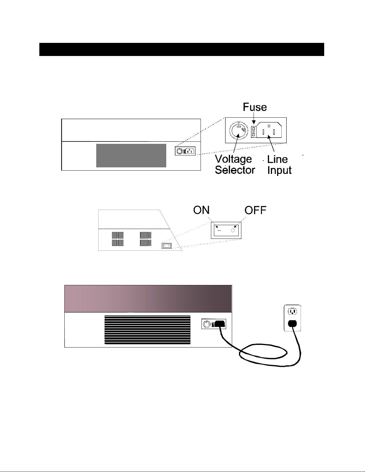
The power cord provided with the P-97 connects to the Power Entry Module located on the
back of the unit (see diagram below). This Module also includes the Line Fuse.
Figure 6-1. P-97 Cabinet (rear view).
Make certain that the Power Switch located on the left end of the P-97 cabinet is turned
OFF.
Figure 6-2. P-97 Cabinet (end view, left).
Plug the power cord provided with the P-97 into the Line Input socket on the Power Entry
Module and then to a power source of the appropriate voltage and frequency.
Figure 6-3. Power connection.
P-97 FLAMING/BROWN MICROPIPETTE PULLER OPERATION MANUAL – REV. 2.03 – DOM (20091301)
Page 20

Page 21
13
7.
7. FR O NT PA N EL
FRON T PANE L
7.7 .
FRON T PANE LF RO NT PAN EL
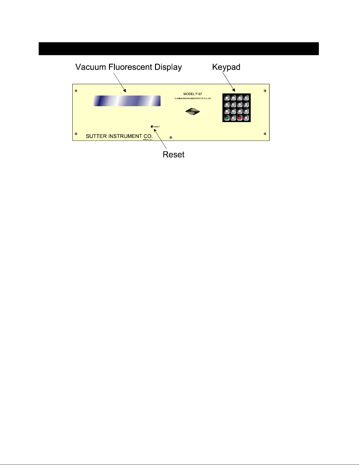
Figure 7-1. P-97 Front Panel.
7.1
7.1 Controls
Controls
7.17.1
ControlsControls
Vacuum Fluorescent Display
Vacuum Fluorescent Display Displays program parameters.
Vacuum Fluorescent DisplayVacuum Fluorescent Display
Reset
Reset Re-initializes the controller.
ResetReset
Ke
Keypad
ypad Used to program parameter values and execute
KeKe
ypadypad
programs.
Keys:
Keys:
Keys:Keys:
0000----9999 Used for choosing the desired program or control
function, entering numeric values when programming
and to make YES/NO (1/0) decisions.
CLR
CLR Used to delete programs or numeric values entered into
CLRCLR
those programs. This key is also used to access the
RAMP TEST.
ENTR
NEXT
ENTR Used to enter new values.
ENTRENTR
NEXT Used to move to the next line in a program while
NEXTNEXT
editing.
LAST
LAST Used to move to the previous line in a program while
LASTLAST
editing.
PULL
STOP
PULL Initiates the execution of a program.
PULLPULL
STOP Aborts the execution of a program.
STOPSTOP
P-97 FLAMING/BROWN MICROPIPETTE PULLER OPERATION MANUAL – REV. 2.03 – DOM (20091301)
Page 22

14
7.2
Write Protection (Off)
Last Date/Time edited
Pressure Setting
Program #
Program Line #
7.2 Display
Display
7.27.2
DisplayDisplay
The P-97 has a two line vacuum fluorescent display for easy viewing from any angle. The
following figure demonstrates what you will see after you have selected a program. A brief
description of each parameter is provided below.
UNLOCKED P=500 JAN 18, 1997 2:30 PM
UNLOCKED P=500 JAN 18, 1997 2:30 PM
UNLOCKED P=500 JAN 18, 1997 2:30 PMUNLOCKED P=500 JAN 18, 1997 2:30 PM
3 1 HEAT=330,PULL=150,VEL.= 80,TIME=200
3 1 HEAT=330,PULL=150,VEL.= 80,TIME=200
3 1 HEAT=330,PULL=150,VEL.= 80,TIME=2003 1 HEAT=330,PULL=150,VEL.= 80,TIME=200
Figure 7-2. Program Display.
PROGRAM
PROGRAM
PROGRAMPROGRAM
(0-99)
A program consists of one or more cycles
when executed in sequence, will ‘pull’ the capillary
1111
1
which,
glass inserted in the instrument. A program can be
up to 8 cycles in length
WRITE PROTECTION
WRITE PROTECTION
WRITE PROTECTIONWRITE PROTECTION
(Locked/Unlocked)
PRESSURE SETTING
PRESSURE SETTING
PRESSURE SETTINGPRESSURE SETTING
(Range 0-999)
DATE/TIME
DATE/TIME Reports the date and time of the last program edit.
DATE/TIMEDATE/TIME
HEAT
HEAT
HEATHEAT
(Range 0-999)
"
locked/unlocked"
}}}}Prevents program from being
edited when in Locked mode.
Reports the programmed value of the air pressure
during the active cooling phase of the pull cycle.
HEAT controls the level of electrical current supplied
to the filament. The HEAT required to melt a piece of
glass is a function of the filament installed and the
particular glass size and composition. It is important
that the HEAT value be set relative to the Ramp Test
value as discussed in the Operation Section.
Generally, changes to HEAT will be made in steps of
about 5 units since in most cases smaller changes will
have little effect.
PULL
PULL
PULLPULL
(Range 0-255)
1
A CYCLE consists of four programmable parameters; H
sequence of events during execution of a cycle is described in the PROGRAMS SECTION of this manual.
P-97 FLAMING/BROWN MICROPIPETTE PULLER OPERATION MANUAL – REV. 2.03 – DOM (20091301)
This parameter controls the force of the hard pull. In
general, the higher the PULL, the smaller the
pipette’s tip diameter and the longer the taper. Useful
changes in PULL strength are 10 units or more to see
an effect.
EAT
, P
ULL
, V
ELOCITY
and either T
IME or DELAY
. A CYCLE is equivalent to one line of program code. The
Page 23

15
VELOCITY
VELOCITY
VELOCITYVELOCITY
(Range 0-255)
TIME
TIME
TIMETIME
(Range 0-255)
The velocity of the glass carriage system is measured
as the glass softens and begins to pull apart under a
constant load. The increasing velocity of the initial
pull is determined by the viscosity of the glass, which
in turn is a function of the glass temperature. The
adjustable velocity allows for a selection of a precise
glass temperature as the trip point for the hard pull.
Useful values for velocity range from 10 to 150 with
lower values being used for patch and injection
pipettes and higher values for micropipettes. SEE
THE PROGRAMS SECTION FOR A DISCUSSION
OF THE SIGNIFICANCE OF VELOCITY=0.
TIME is one of two available modes of cooling and
controls the length of time the cooling air is active. If
VEL>0 then one unit of TIME represents 1/2ms. If
VEL=0 then one unit of TIME represents 10ms. SEE
THE PROGRAMS SECTION FOR A DISCUSSION
OF THE SIGNIFICANCE OF TIME=0.
DELAY
DELAY
DELAYDELAY
(Range 0-255)
DELAY is a cooling mode, which controls the delay
time between when the heat turns off and when the
hard pull is activated. The gas is automatically
turned on for 300ms. The higher the DELAY value,
the cooler the glass will be when the hard pull is
executed. Thus, increasing the DELAY results with
decreased taper length and increased tip diameter. If
VEL>0 then one unit of DELAY represents 1/2ms. If
VEL=0 then one unit represents 10ms. SEE THE
PROGRAMS SECTION FOR A DISCUSSION OF
THE SIGNIFICANCE OF DELAY=0.
P-97 FLAMING/BROWN MICROPIPETTE PULLER OPERATION MANUAL – REV. 2.03 – DOM (20091301)
Page 24

Page 25
17
8.
8. ME CH AN ICAL D ES CRIPTI
MEC H AN ICAL D ES CRIPTI ON (P U LLER A NA TOMY)
8.8 .
MEC H AN ICAL D ES CRIPTIMEC H AN ICAL D ES CRIPTI
8.1
8.1 Some Basic Information
Some Basic Information
8.18.1
Some Basic InformationSome Basic Information
This section presents a basic mechanical description of the P-97, with particular emphasis on
terminology. Knowing the names of the various parts greatly facilitates communication
between the investigators and the manufacturer when discussing adjustments or service
problems. In addition, various controls and adjustments on the top of the instrument are
located and described. Those adjustments, which are considered part of maintenance
procedures, are dealt with in the Maintenance Section of this manual.
8.2
8.2 Air Cooling System
Air Cooling System
8.28.2
Air Cooling SystemAir Cooling System
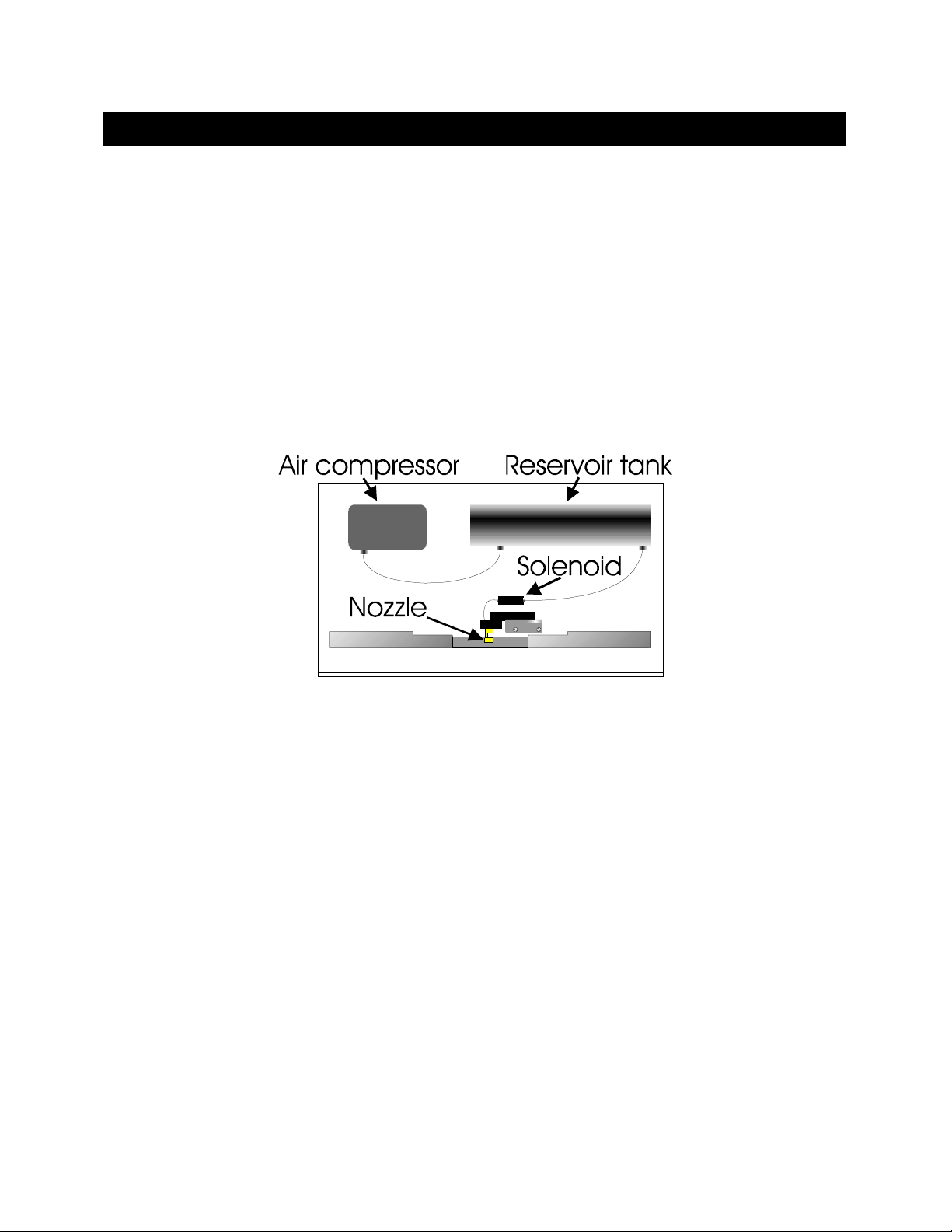
The Model P-97 supplies a blast of air to cool the filament area after the heating segment of a
pull cycle. The components of the air-cooling system are shown below.
ON ( PU LLER A NA TOMY)
ON ( PU LLER A NA TOMY)ON ( PU LLER A NA TOMY)
Figure 8-1. P-97 Base Plate (Top view, cover removed).
Air Compressor
Air Compressor The air compressor (or pump) creates the air pressure used
Air CompressorAir Compressor
to cool the filament and glass during the pull cycle.
Air Jet Nozzle
Air Jet Nozzle Directs the cooling air to the filament. The air jet nozzle
Air Jet NozzleAir Jet Nozzle
should be positioned 2 to 3 millimeters below the filament.
The screw that secures the air jet to the filament block can
be loosened allowing the jet to move up and down.
Air Valve Solenoid
Air Valve Solenoid Regulates the flow of cooling air to the filament and glass.
Air Valve Solenoid Air Valve Solenoid
Drierite Canister
Drierite Canister
Drierite CanisterDrierite Canister
(Reservoir Tank)
(Reservoir Tank)
(Reservoir Tank)(Reservoir Tank)
A canister filled with Drierite used to remove moisture from
the air flowing between the pump and the valve solenoid.
The dissected air is used to purge heat before and after a
pull and to cool the air flowing to the filament and glass
during the pull cycle.
P-97 FLAMING/BROWN MICROPIPETTE PULLER OPERATION MANUAL – REV. 2.03 – DOM (20091301)
Page 26

18
8.3
8.3 Heating Assembly
Heating Assembly
8.38.3
Heating AssemblyHeating Assembly
The Heating Assembly
Heating Assembly comprises the Filament, Filament Block Assembly
Heating AssemblyHeating Assembly
Control Chamber
Control Chamber. The Filament Block Assembly and the Humidity Control Chamber are
Control ChamberControl Chamber
Filament, Filament Block Assembly and the Humidity
Filament, Filament Block AssemblyFilament, Filament Block Assembly
Humidity
Humidity Humidity
discussed below. Filaments are discussed in a separate section.
Humidity Control Chamber
Humidity Control Chamber
Humidity Control ChamberHumidity Control Chamber
Figure
Figure 8888----2222))))
FigureFigure
The chamber encloses the filament block assembly to
provide a controlled environment in which to pull the glass.
Access holes in the side of the chamber allow the glass to be
loaded into position. The chamber must be removed to
access the heating filament. To remove, unscrew the
thumbscrew on the front plate of the chamber, remove the
front plate, and then pull the chamber towards you.
Filament Block Assembly
Filament Block Assembly
Filament Block AssemblyFilament Block Assembly
((((Figure
Figure 8888----2222))))
FigureFigure
Figure 8-2. Filament Block Assembly.
The filament block assembly is made up of several pieces of
hard black nylon. Wires supplying current to the filament
are attached to threaded ‘posts’. This current is carried to
the filament via the upper and lower Brass Jaws
Brass Jaws. Note that
Brass JawsBrass Jaws
these jaws may be moved up and down by loosening the
screws (D)
(D) that secure them to the front of the filament
(D)(D)
block assembly. When changing the filament type from
trough to box (or vice versa), the jaws must be moved up or
down so that the filament is positioned at the correct level
relative to the glass. If the jaws are repositioned and/or the
filament type has been changed, make sure that the
securing screws of the jaws and filament clamp are again
tightened. Failure to tighten these screws can result in, poor
current flow for scorching and insufficient heat to melt the
glass. Please refer to Systematic Filament Replacement in
the Maintenance chapter for additional instructions.
P-97 FLAMING/BROWN MICROPIPETTE PULLER OPERATION MANUAL – REV. 2.03 – DOM (20091301)
Page 27

19
Eccentrics and Angle Plate
Eccentrics and Angle Plate
Eccentrics and Angle PlateEccentrics and Angle Plate
((((Figure
Figure 8888----2222))))
FigureFigure
Cover Plate
Cover Plate
Cover PlateCover Plate
((((Figure
Figure 8888----2222))))
FigureFigure
The Angle Plate secures the Filament Block Assembly to the
Cover Plate; it contains two eccentric adjustments. The two
chrome-plated screws AAAA and BBBB are the eccentrics, and A’
B’
B’ are the corresponding locking screws. By turning the
B’B’
A’ and
A’A’
eccentrics with a screwdriver the Filament Block Assembly
can be moved up and down (A)
(A) or forward and back (B)
(A)(A)
(B) to
(B)(B)
adjust the position of the filament. Loosen the locking
screw associated with each ‘eccentric screw’ before turning,
and tighten after completing the adjustment. Note:
Changing the eccentrics should be made only for fine/small
adjustments.
The cover plate conceals the entry of the Pulling Cables into
the Base of the instrument. It is attached to the top by two
screws, in slots, at points labeled C. Loosening these screws
allows the Filament Block/Angle Plate assembly to move
forward and back over large distances.
NOTE: The movements of the Cover Plate and the Jaws constitute the ‘coarse adjustments’
NOTE: The movements of the Cover Plate and the Jaws constitute the ‘coarse adjustments’
NOTE: The movements of the Cover Plate and the Jaws constitute the ‘coarse adjustments’ NOTE: The movements of the Cover Plate and the Jaws constitute the ‘coarse adjustments’
of filament position, while the eccentric screws a
of filament position, while the eccentric screws allow ‘fine adjustments’.
of filament position, while the eccentric screws aof filament position, while the eccentric screws a
llow ‘fine adjustments’.
llow ‘fine adjustments’.llow ‘fine adjustments’.
P-97 FLAMING/BROWN MICROPIPETTE PULLER OPERATION MANUAL – REV. 2.03 – DOM (20091301)
Page 28

20
8.4
8.4 Upper Pulley Assembly
Upper Pulley Assembly
8.48.4
Upper Pulley AssemblyUpper Pulley Assembly
This assembly guides the Pulling Cables
8888----3333)))) to the centrally located (and concealed) Lower Cable Pulley Assembly
Upper Cable Pulley Assembly
Upper Cable Pulley Assembly is attached to its panel by two screws, in slots (J’ in
Upper Cable Pulley AssemblyUpper Cable Pulley Assembly
8888----3333)))), and contains a large eccentric adjustment screw (J in
Pulling Cables (T in
Pulling CablesPulling Cables
(T in Figure
(T in (T in
Lower Cable Pulley Assembly. Note that the
Lower Cable Pulley AssemblyLower Cable Pulley Assembly
Figure 8888----3333)))) from the Puller Bars
FigureFigure
(J in Figure
Figure 8888----3333)))). This eccentric screw
(J in (J in
FigureFigure
Puller Bars (G in
Puller BarsPuller Bars
(J’ in Figure
(J’ in (J’ in
(G in Figure
Figure
(G in (G in
FigureFigure
Figure
FigureFigure
is used to adjust cable ‘tension’. Its use is covered in the Maintenance Section, and changes
to the settings should not be performed without the supervision of Sutter Instrument
Technical Support.
Figure 8-3. Upper cable pulley assembly.
Panels, Left And Right
Panels, Left And Right
Panels, Left And RightPanels, Left And Right
(K in
(K in Figure
Figure 8888----3333))))
(K in (K in
FigureFigure
The panels are the angled surfaces that provide
mountings for the Puller Bars and their Bearings, the
Spring Stops, the Bumpers, and the Upper Cable
Pulley Assemblies. Except for minor differences in
shape, the left and right Panels are mirror images of
each other. Note the three socket-head cap screws
that attach each Panel to the base plate top. These
screws are used to align the Puller Bars. Their
adjustment, if necessary, is covered in the
Maintenance Section. Contact Sutter Instrument
Technical Support for more instructions on how the
panels are aligned.
Bumpers
Bumpers
BumpersBumpers
(N in
(N in Figure
Figure 8888----3333))))
(N in (N in
FigureFigure
Spring Stops
Spring Stops
Spring StopsSpring Stops
(P in
(P in Figure
Figure 8888----3333)
(P in (P in
FigureFigure
Puller Bars
Puller Bars
Puller BarsPuller Bars
(G in
(G in Figure
Figure 8888----3333))))
(G in (G in
FigureFigure
P-97 FLAMING/BROWN MICROPIPETTE PULLER OPERATION MANUAL – REV. 2.03 – DOM (20091301)
)
) )
The Bumper stops the motion of its associated Puller
Bar. Each Bumper also prevents impact forces from
breaking pipettes.
The Spring Stops are one-way catches that catch the
Puller Bars as they rebound off the Bumpers so as to
prevent pipette tip collision.
This assembly consists of the puller bar, threaded
post, electrode clamp knob, and cable retaining screw.
The cable retaining screw (H)
shallow groove (I)
(I) at the end of the puller bar, and
(I)(I)
(H) holds the cable in a
(H)(H)
forms the ‘resistance’ against which the cable ends
pull. The puller bar is made of mild steel and coated
with a controlled thickness of hard chrome. Glass is
loaded into the groove near the tip of the puller bar
Page 29

21
VVVV---- Bearings
Bearings
Bearings Bearings
(S in
(S in Figure
Figure 8888----3333))))
(S in (S in
FigureFigure
Pull Cable
Pull Cable
Pull CablePull Cable
(T in
(T in Figure
Figure 8888----3333))))
(T in (T in
FigureFigure
and is held in position by tightening down the
clamping knob (R)
(R).
(R)(R)
These bearings are the guides for the Puller Bar
motion. They are made of stainless steel and must
NEVER
NEVER be oiled (see Maintenance Section). Note
NEVERNEVER
that these bearings are mounted on stainless steel
bushings, one of which is round with the other two
being hexagonal. The hexagonal (eccentric) bushings
are used to adjust position and ease of travel of the
PULLER BARS (see Maintenance Section). Do not
adjust the eccentrics without additional instruction.
This cable transmits the pulling force of the solenoid
to the Puller Bars via the Upper (F)
(F) and Lower Pulley
(F)(F)
Assemblies. It is made of flexible metal with a nylon
coating. Never pinch or distort the cable. The cable
is terminated with crimped-on clamps or ‘swages’ at
the back-end of each Puller Bar.
8.5
8.5 Cabinet
Cabinet
8.58.5
CabinetCabinet
Baseplate
Baseplate The top think metal plate on which the mechanical
BaseplateBaseplate
assemblies are mounted.
Base
Base The Base includes the cabinet to which the top
BaseBase
Baseplate is mounted as well as the transformers and
the circuit board contained within.
8.6
8.6 Electronics
Electronics
8.68.6
ElectronicsElectronics
The P-97 micropipette puller is controlled by a Z-80 microprocessor. Three digital-to-analog
(D-A) converters control the HEAT, PULL and VELOCITY values. The HEAT power supply
is a precision constant current switching unit, which will vary less than 10 milliamperes with
a plus or minus 10% change in the AC line current. The PULL supply is a constant current
DC power supply. The velocity trip point is set by a D-A converter. The output of the velocity
transducer is compared to the output of the velocity D-A to determine when the trip velocity
is reached.
P-97 FLAMING/BROWN MICROPIPETTE PULLER OPERATION MANUAL – REV. 2.03 – DOM (20091301)
Page 30

Page 31

23
9.
9. FI RS T TIME U SE
FIR S T TIME U SE
9.9 .
FIR S T TIME U SEF IR ST T IME U S E
While we realize that most new users of the P-97 are anxious to start pulling useable pipettes
right away, we cannot over-state the importance of taking a few moments to review the
manual in order to understand how the puller works. Many a heating filament has been
destroyed with first use because the user did not understand the relationship between the
programmable heat settings and the filament installed in the puller. If you absolutely must
use the puller before reading through the manual, the following instructions are provided to
help you get going and keep you from vaporizing your heating filament.
1. Make certain that the P-97 is plugged into the power outlet of the correct voltage and
frequency.
2. Remove the rubber bands holding the puller bars together.
3. Turn Power switch on left side of cabinet ON
4. Press < 0 > followed
flashing on the HEAT
< 0 > followed by < ENTR >
< 0 > followed< 0 > followed
HEAT parameter.
HEATHEAT
< ENTR > on the keypad to view Program 0. The cursor will be
< ENTR > < ENTR >
ON.
ONON
5. Inspect the parameter values displayed for Program 0. Program 0 should display the
factory-installed values listed on the enclosed program sheet. If the values vary, jot down
the values displayed and then re-enter the program sheet values.
CAUTION: The program HEAT value should not exceed the listed RAMP TEST value by
CAUTION: The program HEAT value should not exceed the listed RAMP TEST value by
CAUTION: The program HEAT value should not exceed the listed RAMP TEST value by CAUTION: The program HEAT value should not exceed the listed RAMP TEST value by
more than 10 units.
more than 10 units.
more than 10 units. more than 10 units.
6. Load a piece of the supplied sample glass into puller as follows:
Figure 9-1. Left puller bar.
a. Loosen both clamping knobs (loosening both knobs is recommended so as to avoid
breaking the glass as it is passed through).
b. Place glass in V-groove in puller bar, slide it beyond clamp about 2 cm and tighten
knob.
c. Depress the spring stop on each puller bar to release them from their catch position.
d. Pull both bars towards each other using the finger bars. Hold bars in position using
the thumb and index finger from one hand. The hex head screw should be touching
the end of the slot in both puller bars.
P-97 FLAMING/BROWN MICROPIPETTE PULLER OPERATION MANUAL – REV. 2.03 – DOM (20091301)
Page 32

24
e. Loosen both clamping knobs; carefully slide glass through the holes in the side of the
heater chamber and into V-groove of opposite puller bar.
f. Tighten down clamping knobs.
7. Press the < PULL >
< PULL > key on the keypad. The heating filament should turn on and the
< PULL >< PULL >
glass should separate in less than 10 seconds.
8. Loosen the clamping knobs and remove the pipettes from the puller bars.
Unless otherwise stated on your program sheet, Program 0 is factory pre-programmed to pull
a micropipette (tip diameter less than 0.1 mm) from 1.0mm x 0.5mm borosilicate glass.
Program 1 is factory pre-programmed to pull a patch type pipette with a tip diameter of
about 2mm. To try the patch pipette program (#1):
1. Press RESET to exit Program 0
2. Press < 1 >
< 1 > followed by < ENTR >
< 1 > < 1 >
< ENTR > to enter into Program 1.
< ENTR > < ENTR >
3. Repeat Steps 4-7 above.
P-97 FLAMING/BROWN MICROPIPETTE PULLER OPERATION MANUAL – REV. 2.03 – DOM (20091301)
Page 33

25
10.
10. PR OG RA MS
PROG RA MS
10.10 .
PROG RA MSPROGR A MS
10.1
10.1 Program Structure
Program Structure
10.110.1
Program StructureProgram Structure
The resulting size and shape of a micropipette made using the P-97 is determined by the
parameter values that are programmed by the user. One hundred (100) separate programs
can be saved for future use. Each program is structured as follows:
Program
Program Consists of one or more Lines, each of which represents a pull cycle.
ProgramProgram
When a program is run, all lines within the program are sequentially
executed, beginning with Line 1. As a line is executed, the capillary glass
inserted in the instrument is “pulled.” A program can be up to 8
lines/cycles in length.
Cyc
Cycle
le A Cycle
CycCyc
lele
Cycle consists of five programmable parameters; Heat
CycleCycle
either Time
Program code.
Time or Delay,
TimeTime
Delay, and Pressure
Delay, Delay,
Pressure. A Cycle
Pressure Pressure
Cycle is equivalent to one line of
CycleCycle
Heat, Pull
Pull, Velocity
HeatHeat
PullPull
Velocity,
VelocityVelocity
10.2
10.2 Program Line Pull Cycle Parameters
Program Line Pull Cycle Parameters
10.210.2
Program Line Pull Cycle ParametersProgram Line Pull Cycle Parameters
Each of the four programmable parameters in a Cycle is defined below:
HEAT
HEAT HEAT controls the level of electrical current supplied to the filament.
HEATHEAT
The HEAT required to melt a piece of glass is a function of the filament
installed and the particular glass size and composition. It is important
that the HEAT value be set relative to the Ramp Test value as discussed
in the Operation Section. Generally, changes to HEAT will be made in
steps of about 5 units since in most cases smaller changes will have little
effect.
PULL
PULL
PULLPULL
(Range 0-255)
This parameter controls the force of the hard pull. In general, the
higher the pull, the smaller the pipette’s tip diameter and the longer its
taper. Useful changes in PULL strength are 10 units or more to see an
effect.
NOTE: A one-line program containing PULL = 0 and a low VELOCITY
setting (15 – 40), looped 2-3 times, can be used for making short patchtype pipettes.
P-97 FLAMING/BROWN MICROPIPETTE PULLER OPERATION MANUAL – REV. 2.03 – DOM (20091301)
Page 34

26
VELOCITY
VELOCITY
VELOCITYVELOCITY
(Range 0-255)
TIME
TIME
TIMETIME
(Range 0-255)
The VELOCITY of the glass carriage system is measured as the glass
softens and begins to pull apart under a constant load. The increasing
velocity of the initial pull is determined by the viscosity of the glass,
which in turn is a function of the glass temperature. The adjustable
velocity allows for the selection of a precise glass viscosity as the trip
point for the hard pull. Useful values for velocity range from 10 to 150,
with lower values (15-40) being used for patch pipettes and higher
values (50-125) for microinjection pipettes. ..
VELOCITY = 0 Special Condition (Fire Polish Mode):
VELOCITY = 0 Special Condition (Fire Polish Mode): If VEL=0 and
VELOCITY = 0 Special Condition (Fire Polish Mode): VELOCITY = 0 Special Condition (Fire Polish Mode):
PULL=0, the HEAT will be on for the duration of the TIME
programmed (1 unit equals 10ms). This feature allows you to use the
puller to fire polish the resulting patch pipette...
Controls the length of time the cooling air is active. This parameter is
one of two available modes of cooling If VEL>0 then one unit of TIME
represents 1/2ms. If VEL=0 then one unit of TIME represents 10ms.
TIME = 0 Special Condition:
TIME = 0 Special Condition: The air solenoid is disabled when TIME=0
TIME = 0 Special Condition: TIME = 0 Special Condition:
(no active cooling). This allows the pulling of special pipette shapes.
Most often used to pull long tube-like shapes such as those used for
microperfusion.
DELAY
DELAY
DELAYDELAY
(Range 0-255)
A cooling mode that controls the delay time between when the HEAT
turns off and when the hard PULL is activated. The air is automatically
turned on for 300ms. The higher the DELAY value, the cooler the glass
will be when the hard PULL is executed. Thus, increasing the DELAY
results in decreased taper length and increased tip diameter. If VEL>0
then one unit of DELAY represents 1/2ms. If VEL=0 then one unit
represents 10ms.
DELAY = 0 Special Condition:
DELAY = 0 Special Condition: The air solenoid is disabled when
DELAY = 0 Special Condition: DELAY = 0 Special Condition:
DELAY = 0 (no active cooling). This allows the pulling of special
pipette shapes. Most often used to pull long tube-likes shapes such as
those used for aspiration, microperfusion, or holding.
10.3
10.3 Pull Cycle
Pull Cycle
10.310.3
Pull CyclePull Cycle
A typical pull cycle in a program line is described below:
1. The heat turns on.
1. The filament heats up, the glass softens, and a weak pull draws the glass out until it
reaches the programmed velocity.
2. When the programmed velocity has been reached, the heat turns off, and the air turns on
to cool the filament and glass.
3. If TIME is greater than 0 (zero), the hard pull (if any) is executed after a short delay (less
than 50ms) and then the air is activated for the specified TIME.
P-97 FLAMING/BROWN MICROPIPETTE PULLER OPERATION MANUAL – REV. 2.03 – DOM (20091301)
Page 35

27
If DELAY is greater than 0 (zero), the air is activated for a short period (less than 400ms)
and then the hard pull is activated after the specified DELAY.
10.4
10.4 Default Configuration
Default Configuration
10.410.4
Default ConfigurationDefault Configuration
Unless special programming or setup was requested at the time of purchase, the puller was
setup and shipped with the following standard factory configuration:
Table 10-1. Standard Factory Configuration.
Heating Filament Installed
Heating Filament Installed 3mm Trough (Catalog #FT330B
Heating Filament InstalledHeating Filament Installed
3mm Trough (Catalog #FT330B))))
3mm Trough (Catalog #FT330B3mm Trough (Catalog #FT330B
Glass used to program puller
(sample sent with puller)
Factory installed programs
(see enclosed program sheet)
1.0mm O.D. x 0.5mm I.D. borosilicate,
without internal filament (catalog #B100-50-10)
0 -Micropipette (tip diameter less than 0.1 µm
1 -Patch type pipette
In describing the operation of the puller, the above configuration is assumed. If the
configuration of your puller differs, the operating instructions still apply but references to
specific program settings may not be accurate. Inappropriate settings will, in general, only
affect your ability to control the geometry of the glass micropipette you are trying to
fabricate. However, the heating filament can be destroyed by an excessive value for the
HEAT parameter
HEAT parameter. We recommend you refrain from executing a program until you have read
HEAT parameterHEAT parameter
the heating filament can be destroyed by an excessive value for the
the heating filament can be destroyed by an excessive value for the the heating filament can be destroyed by an excessive value for the
through this section of the manual and have run the Ramp Test described herein.
10.5
10.5 Selecting a Program
Selecting a Program
10.510.5
Selecting a ProgramSelecting a Program
< 0 to 99 >
< 0 to 99 >
< 0 to 99 >< 0 to 99 >
After applying power to the instrument, a “power on” reset will occur and the display will
appear as follows:
WHICH PROGRAM DO YOU WANT? (0-99)
WHICH PROGRAM DO YOU WANT? (0-99)
WHICH PROGRAM DO YOU WANT? (0-99)WHICH PROGRAM DO YOU WANT? (0-99)
COPYRIGHT SUTTER INSTRUMENT CORP. 1992
COPYRIGHT SUTTER INSTRUMENT CORP. 1992
COPYRIGHT SUTTER INSTRUMENT CORP. 1992 COPYRIGHT SUTTER INSTRUMENT CORP. 1992
Figure 10-1. Power-On Display.
The P-97 has the capacity to store 100 programs (0 - 99). On the keypad, press < 0 >
followed by < ENTR
program you wish to execute. The display will appear as shown below in Figure
ENTR > (factory installed micropipette program) or the number of another
ENTRENTR
Figure 10
FigureFigure
10----2222
1010
(numerical values may vary). Please refer to the FRONT PANEL chapter and the beginning
of this chapter for a full description of the PARAMETERS shown.
UNLOCKED P=500 JAN 18, 1997 2:30 PM
UNLOCKED P=500 JAN 18, 1997 2:30 PM
UNLOCKED P=500 JAN 18, 1997 2:30 PMUNLOCKED P=500 JAN 18, 1997 2:30 PM
3 1 HEAT=330,PULL=150,VEL.= 80,TIME=200
3 1 HEAT=330,PULL=150,VEL.= 80,TIME=200
3 1 HEAT=330,PULL=150,VEL.= 80,TIME=2003 1 HEAT=330,PULL=150,VEL.= 80,TIME=200
Figure 10-2. P-97 Program Display.
P-97 FLAMING/BROWN MICROPIPETTE PULLER OPERATION MANUAL – REV. 2.03 – DOM (20091301)
Page 36

28
To select a different program, Press < RESET
press the number of the desired program (0 to 99)
followed by < ENTR
10.6
10.6 Viewing a Program
Viewing a Program
10.610.6
Viewing a ProgramViewing a Program
< NEXT > / < LAST >
< NEXT > / < LAST >
< NEXT > / < LAST >< NEXT > / < LAST >
The front panel display limits you to viewing only two adjacent lines of a PROGRAM at one
time. When you first select a PROGRAM, the display above will appear. The top line of
every program is a header line, which displays the PRESSURE setting, the WRITE
PROTECT STATUS and the LAST EDIT DATE. The second line of the display is Line 1 of
program.
To view additional lines of the
program
Press the < NEXT
RESET > to bring up the sign-on prompt then
RESETRESET
ENTR >.
ENTRENTR
NEXT > key
NEXTNEXT
To scroll to previous lines Press the < LAST
10.7
10.7 Clearing a Program from Memory
Clearing a Program from Memory
10.710.7
Clearing a Program from MemoryClearing a Program from Memory
< CLR >
< CLR >
< CLR >< CLR >
To clear the values of a particular program from memory you can utilize the CLEAR
function.
Pressing the < CLR >
Entering < 1111 > will clear the PROGRAM from the line the cursor is on to the end of the
PROGRAM. If the cursor is on Line 1, the entire program will be cleared from memory. If
the cursor is on Line 2, Line 1 will be preserved, and lines 2-8 will be cleared.
10.8
10.8 Editing a Program
Editing a Program
10.810.8
Editing a ProgramEditing a Program
Select a program number (e.g. 10). If there are already values entered, make sure that this
program was not entered by another user of the puller. Unused program areas are usually
cleared before a puller is shipped, but occasionally test program values are inadvertently left
in memory. We recommend that unused programs be cleared before proceeding.
< CLR > key gives you the following message:
< CLR >< CLR >
UNLOCKED P=500 JAN 18, 1997 2:30 PM
UNLOCKED P=500 JAN 18, 1997 2:30 PM
UNLOCKED P=500 JAN 18, 1997 2:30 PMUNLOCKED P=500 JAN 18, 1997 2:30 PM
3 1 HEAT=330,PULL=150,VEL.= 80,TIME=200
3 1 HEAT=330,PULL=150,VEL.= 80,TIME=200
3 1 HEAT=330,PULL=150,VEL.= 80,TIME=2003 1 HEAT=330,PULL=150,VEL.= 80,TIME=200
Figure 10-3. Clear Program Display.
LAST > key.
LASTLAST
10.8.1
10.8.1 Entering a New Program
10.8.110.8.1
After selecting or clearing a program area, the cursor will be blinking at the HEAT
parameter on Line 1. To familiarize yourself with program entry, enter the following sample
micropipette program:
Entering a New Program
Entering a New ProgramEntering a New Program
P-97 FLAMING/BROWN MICROPIPETTE PULLER OPERATION MANUAL – REV. 2.03 – DOM (20091301)
Page 37

29
HEAT
HEAT PULL
HEATHEAT
300 150 100 150
PULL VELOCITY
PULLPULL
VELOCITY TIME
VELOCITYVELOCITY
TIME
TIMETIME
Press the series of numbers < 300 > to enter the HEAT value of 300. The cursor will
automatically tab over to the PULL parameter.
Enter < 150 > for PULL. The cursor will tab over to the VELOCITY parameter.
Enter < 90 > for VELOCITY. The cursor will remain there, blinking. Note that when less
than three digits are entered, the cursor will not automatically tab to the next field.
than three digits are entered, the cursor will not automatically tab to the next field. You
than three digits are entered, the cursor will not automatically tab to the next field.than three digits are entered, the cursor will not automatically tab to the next field.
must press < ENTR
ENTR > to enter the value and tab to the next field.
ENTRENTR
Note that when less
Note that when less Note that when less
Enter < 150 > for TIME. The cursor will tab to the next field, which is HEAT in Line 2.
10.8.2
10.8.2 Editing an Existing Program
10.8.210.8.2
Editing an Existing Program
Editing an Existing ProgramEditing an Existing Program
To edit the value of a parameter(s) in a particular line, the cursor must be blinking in the
field you want to edit. If necessary, press < NEXT >
want to change. Press < ENTR >
< ENTR > to tab the cursor to the field you want to change, and
< ENTR >< ENTR >
< NEXT > or < LAST >
< NEXT >< NEXT >
< LAST > to scroll to the line you
< LAST >< LAST >
enter the new value. In our example above, to change the value of VELOCITY in Line 1 you
first press < LAST >
< LAST > to scroll up to Line 1. Then press < ENTR >
< LAST >< LAST >
< ENTR > two times to tab over to
< ENTR >< ENTR >
the VELOCITY field. Note that the values for HEAT and PULL remain unchanged. Enter a
new value (e.g. 90); if the value is two digits, you must press < ENTR >
The cursor will be positioned on Line 1 in the TIME field. To move to Line 2, press < ENTR
< ENTR > to enter the value.
< ENTR > < ENTR >
< ENTR
< ENTR < ENTR
>>>> to “tab” over to the HEAT field in Line 2.
The program values above are only given to demonstrate data entry procedures. Useful
program values to pull the pipette that you want will be discussed in the next chapter. In
general, inappropriate settings will only affect your ability to control the geometry of the
glass micropipette you are trying to fabricate. However, the heating element can be
des
destroyed by an excessive value for the HEAT parameter
troyed by an excessive value for the HEAT parameter. Do not use HEAT settings greater
desdes
troyed by an excessive value for the HEAT parametertroyed by an excessive value for the HEAT parameter
than those found in programs 0 and 1 until you have run the RAMP TEST
than those found in programs 0 and 1 until you have run the RAMP TEST described in the
than those found in programs 0 and 1 until you have run the RAMP TEST than those found in programs 0 and 1 until you have run the RAMP TEST
the heating element can be
the heating element can be the heating element can be
Do not use HEAT settings greater
Do not use HEAT settings greater Do not use HEAT settings greater
next section.
P-97 FLAMING/BROWN MICROPIPETTE PULLER OPERATION MANUAL – REV. 2.03 – DOM (20091301)
Page 38

Page 39

31
11.
11. SO FT WA RE CON TR OL FUN
SOF T WA RE CON TR OL F UNCT IO NS
11.11 .
SOF T WA RE CON TR OL F UNSOF T WA RE CON TR OL F UN
CTIO N S
CTIO N SC TI ON S
The P-97 has several unique software CONTROL FUNCTIONS that allow you to, among
other things, run SELF-TEST procedures, set up some of the PULL CONDITIONS and
WRITE-PROTECT your program. These CONTROL FUNCTIONS are accessed through the
< CLR
CLR > key. Pressing < CLR
CLRCLR
CLR > gives you the following message:
CLRCLR
DO YOU WISH TO CLEAR ALL VALUES FROM THE
DO YOU WISH TO CLEAR ALL VALUES FROM THE
DO YOU WISH TO CLEAR ALL VALUES FROM THEDO YOU WISH TO CLEAR ALL VALUES FROM THE
PRESENT CYCLE TO THE END? NO=
PRESENT CYCLE TO THE END? NO=0 YES=1
PRESENT CYCLE TO THE END? NO=PRESENT CYCLE TO THE END? NO=
0 YES=1
0 YES=10 YES=1
Figure 11-1. Access to Control Functions.
Entering < 0 >
< 0 > will provide you with access to the following P-97 CONTROL FUNCTIONS:
< 0 >< 0 >
Table 11-1. Control Functions.
Function
Function
Function Function
####
Function Name
Function Name Description
Function NameFunction Name
Description
DescriptionDescription
1 RAMP TEST Run the Ramp Test
2 CHANGE AIR PRESSURE Set the air pressure for a program
3 AIR MODE Select the active cooling mode
4 AIR TIME AT START OF PULL
5 AIR TIME AT END OF PULL Purge chamber at end of pull
6 RESET TIME AND DATE Set the clock
7
8 MEMORY TEST Test the integrity of the RAM
WRITE-PROTECT THE
PROGRAM
Dehumidify the heating chamber prior
to pulling.
Lock or unlock the write protection
The eight CONTROL FUNCTIONS will scroll along the bottom line of the display. Select
the desired CONTROL FUNCTION by pressing the corresponding numeric key. Each
CONTROL FUNCTION is more completely described below.
11.1
11.1 RAMP TEST < 1 >
RAMP TEST < 1 >
11.111.1
RAMP TEST < 1 > RAMP TEST < 1 >
The HEAT value required to melt your glass is based on the characteristics of the heating
filament that is installed and the glass you are using. The RAMP TEST allows you to
systematically establish or adjust program HEAT values as a function of the filament/glass
combination. This test should be run when using the puller for the first time, before writing
or editing a program, whenever you change glass or whenever you change the heating
filament.
P-97 FLAMING/BROWN MICROPIPETTE PULLER OPERATION MANUAL – REV. 2.03 – DOM (20091301)
Page 40

32
To run a RAMP TEST:
1. Go into any program. For example, Press <1>
2. Press <CLR>
3. Press <0>
4. Select <1>
5. Install glass and press <PULL>
<CLR>
<CLR><CLR>
<0> to not clear parameters
<0><0>
<1> for RAMP TEST
<1><1>
<PULL>
<PULL><PULL>
<1> and then <ENTR>
<1><1>
<ENTR> to select Program 1
<ENTR><ENTR>
When executed, events in the RAMP TEST take place as follows:
1. The puller increments the HEAT at the rate of 650 milliamps per second, and the
filament, after 1-2 minutes, begins to get hot and glows orange in color.
2. The puller bars begin to move apart as the HEAT output begins to soften the glass.
3. The HEAT is turned off when a certain velocity (the value of which is stored in ROM) is
achieved.
4. The RAMP TEST value shown on the display is the HEAT value that was required to
reach the factory-set RAMP TEST velocity.
To interrupt the RAMP TEST or reset the display press RESET.
Recommendations
Recommendations
RecommendationsRecommendations
Table 11-2. Maximum heat and recommended starting values for different filament shapes.
Filament
Filament Maximum/Recommended
FilamentFilament
Maximum/Recommended Value(s)
Maximum/RecommendedMaximum/Recommended
Value(s)
Value(s)Value(s)
Maximum program HEAT value(s) Ramp value + 35 units. Trough
Recommended starting value Ramp value+ 15 units.
Maximum Program HEAT value(s) Ramp value + 30 units. Box
Recommended starting value Ramp value.
Additional guidelines for setting program HEAT values relative to RAMP TEST values are
given in the Programming Section of this manual. HEAT sett
damage or burn out the filament.
damage or burn out the filament.
damage or burn out the filament.damage or burn out the filament.
11.2
11.2 CHANGE AIR PRESSURE < 2 >
CHANGE AIR PRESSURE < 2 >
11.211.2
CHANGE AIR PRESSURE < 2 >CHANGE AIR PRESSURE < 2 >
HEAT settings over RAMP +35 can
HEAT settHEAT sett
ings over RAMP +35 can
ings over RAMP +35 can ings over RAMP +35 can
This control sets the pressure generated by the air compressor during the active cooling
phase of the pull cycle. Each time a pull is started the air pressure is corrected before the
filament turns on. A value must be entered each time this function is accessed. Changes of
less than 10 units will not be noticeable. Air pressure is reported on the program header
line.
Range
Range 1 to 999
RangeRange
P-97 FLAMING/BROWN MICROPIPETTE PULLER OPERATION MANUAL – REV. 2.03 – DOM (20091301)
Page 41

33
phase. The onset of the hard pull is set at 40ms. One unit of
Default
Default 500
DefaultDefault
Recommendations
Recommendations
RecommendationsRecommendations
For thick walled glass 500
For thin walled glass 300
11.3
11.3 AIR MODE < 3 >
AIR MODE < 3 >
11.311.3
AIR MODE < 3 >AIR MODE < 3 >
Select between one of two modes of cooling during the active cooling phase of the pull cycle.
The mode is reported in the fourth field of each program line.
TIME MODE
TIME MODE Controls the length of time the gas is on during the cooling
TIME MODETIME MODE
TIME is equal to 1/2 millisecond (e.g., at a setting of 150 the
cooling air will be on for 75ms).
DELAY MODE
DELAY MODE Controls the onset of the hard pull. The gas is turned on for
DELAY MODEDELAY MODE
300 ms during the cooling phase. One unit of DELAY is
equal to 1/2 millisecond (e.g. a setting of 80 will delay the
onset of the hard pull by 40 ms).
Default
Default TIME MODE
DefaultDefault
Recommendations
Recommendations
RecommendationsRecommendations
TIME MODE
TIME MODETIME MODE
Use the TIME MODE for: Patch pipette programs
Glass <1.2mm O.D.
Transfer of model P-87 puller programs to P-97
Use the DELAY MODE for: Single cycle programs
Glass >1.2mm O.D.
Transfer of model P80-PC puller programs to P-97.
11.4
11.4 AIR TIME AT START OF PULL < 4 >
AIR TIME AT START OF PULL < 4 >
11.411.4
AIR TIME AT START OF PULL < 4 >AIR TIME AT START OF PULL < 4 >
Controls the length of time the humidity control chamber is purged with dehumidified air
prior to execution of the pull sequence. The intent of the control is to minimize and stabilize
the chamber humidity during the pull sequence. Units are in seconds.
Range
Range 1 to 255 seconds
RangeRange
Default
Default 5 seconds
DefaultDefault
Recommendations
Recommendations
RecommendationsRecommendations
For humid environments 20 to 30 seconds
P-97 FLAMING/BROWN MICROPIPETTE PULLER OPERATION MANUAL – REV. 2.03 – DOM (20091301)
Page 42

34
11.5
11.5 AIR TIME AT END OF PULL < 5 >
AIR TIME AT END OF PULL < 5 >
11.511.5
AIR TIME AT END OF PULL < 5 >AIR TIME AT END OF PULL < 5 >
Controls the length of time the chamber is cooled after completion of the pull and the length
of time the end of pull information is displayed. Units are in seconds. The time you enter is
actually an offset added to an automatic 3 second chamber cooling cycle [e.g. A setting of 5
would result with 8 seconds of chamber cooling].
Range
Range 0 to 255 seconds
RangeRange
Default
Default 5 seconds
DefaultDefault
Recommendations
Recommendations
RecommendationsRecommendations
For single cycle programs 5 seconds
For multicycle programs
(to allow additional cooling of the
heating clamp assembly)
11.6
11.6 RESET TIME AND DATE < 6 >
RESET TIME AND DATE < 6 >
11.611.6
RESET TIME AND DATE < 6 >RESET TIME AND DATE < 6 >
This function allows you to set the system clock. The clock is used to establish the date and
time of the last program edit as displayed on the program header line.
11.7
11.7 WRITE
WRITE----PROTECT THE PROGRAM < 7 >
11.711.7
WRITEWRITE
Activate (lock) or inactivate (unlock) the WRITE PROTECTION mode. Unlocked mode (0)
allows program to be edited. Locked mode (1) prevents program from being edited. The
write-protect status is reported on the program header line.
Default
Default Unlocked
DefaultDefault
11.8
11.8 MEMORY TEST < 8 >
MEMORY TEST < 8 >
11.811.8
MEMORY TEST < 8 >MEMORY TEST < 8 >
Performs a non-destructive test of the RAM. Press RESET to reset the system after
performing this test.
PROTECT THE PROGRAM < 7 >
PROTECT THE PROGRAM < 7 >PROTECT THE PROGRAM < 7 >
25 seconds
P-97 FLAMING/BROWN MICROPIPETTE PULLER OPERATION MANUAL – REV. 2.03 – DOM (20091301)
Page 43

35
12.
12. PU L LING PI PE TT ES
PUL L IN G PIPE TT ES
12.12 .
PUL L IN G PIPE TT ESPUL L IN G PIPE TT ES
12.1
12.1 Procedures
Procedures
12.112.1
ProceduresProcedures
Prior to pulling a pipette for the first time, it is important to establish what HEAT value is
appropriate to melt your glass. Before executing a program for the first time, run the RAMP
TEST
TEST as previously described, and note the Ramp value reported. The HEAT settings in the
TESTTEST
factory-installed programs are typically set at Ramp value plus 15 units. If your Ramp test
value differs from the factory Ramp value, adjust the HEAT in your programs to your Ramp
value plus 15 units.
Once you have adjusted the HEAT value relative to the Ramp value, pulling a pipette is very
straightforward. Try executing the factory installed programs with the sample glass to
acquaint yourself with the pulling process.
1. Load the glass into the puller as described previously in the FIRST TIME USE chapter.
2. Press < 0 > followed by < ENTR > on the keypad to view Program 0.
run the RAMP
run the RAMP run the RAMP
3. Inspect the parameter values displayed for Program 0. Program 0 should display the
factory-installed values listed on the enclosed program sheet. Adjust the HEAT setting to
your Ramp value plus 15 units.
4. Press the < PULL > key on the keypad. The heating filament will turn on and the glass
should separate within 10 seconds. The display will then report the number of heating
cycles and the total time that the heat was on, similar to the following:
THE PROGRAM LOOPED 01 TIMES. THE LAST
THE PROGRAM LOOPED 01 TIMES. THE LAST
5. Loosen the clamping knobs and remove the pipettes from the puller bars.
Unless otherwise stated on your program sheet, Program 0 is factory pre-programmed to pull
a micropipette (tip diameter less than 0.1 mm) from 1.0mm x 0.5 mm borosilicate glass. It
will pull the pipette in one heating cycle or ‘loop’. The time reported is very useful for
developing programs and will be discussed in the Parameter Adjustment section of this
manual.
A unique feature of the P-97 is its capability to loop through a program. This is
demonstrated with the multicycle Program 1, which is factory pre-programmed to pull a
patch type pipette with a tip diameter of about 2mm. Press RESET to exit Program 0, and
then press < 1111 > followed by < ENTR
should read similar to the following:
THE PROGRAM LOOPED 01 TIMES. THE LASTTHE PROGRAM LOOPED 01 TIMES. THE LAST
LINE USED WAS 01, HEAT ON SEC. = 6.05
LINE USED WAS 01, HEAT ON SEC. = 6.05
LINE USED WAS 01, HEAT ON SEC. = 6.05LINE USED WAS 01, HEAT ON SEC. = 6.05
Figure 12-1. Pull Cycle Report.
ENTR > to enter into Program 1. The display for Program 1
ENTRENTR
P-97 FLAMING/BROWN MICROPIPETTE PULLER OPERATION MANUAL – REV. 2.03 – DOM (20091301)
Page 44

36
UNLOCKED P=500 JAN 18, 1997 2:35 PM
UNLOCKED P=500 JAN 18, 1997 2:35 PM
UNLOCKED P=500 JAN 18, 1997 2:35 PMUNLOCKED P=500 JAN 18, 1997 2:35 PM
1 1 HEAT=285,PULL= 0,VEL.= 50,TIME=150
1 1 HEAT=285,PULL= 0,VEL.= 50,TIME=150
1 1 HEAT=285,PULL= 0,VEL.= 50,TIME=1501 1 HEAT=285,PULL= 0,VEL.= 50,TIME=150
Figure 12-2. Sample program.
Adjust the HEAT in the program to the Ramp value. Load glass into the puller and press <
PULL >
PULL >. The heating filament should cycle on and off repeatedly. When the pull is
PULL >PULL >
complete, the display should read similar to the following:
THE PROGRAM LOOPED 04 TIMES. THE LAST
THE PROGRAM LOOPED 04 TIMES. THE LAST
After the heat turns on in line 01, the glass heats up and draws apart until it reaches a
VELOCITY of 50, at which point the heat turns off and the cooling air turns on. The puller
is “aware” of the fact that the glass has not separated yet, and will go back to line 01 of the
program and try again; in effect, it begins ‘looping’. It will continue to do so until the glass
separates. This looping capability is particularly useful for fabricating patch pipettes, which
require multiple heating cycles to form the characteristic stubby geometry.
12.2
12.2 Notes on Program Operation
Notes on Program Operation
12.212.2
Notes on Program OperationNotes on Program Operation
There is always the possibility that the puller will be given a set of values that ‘stall’ its
operation. For example, the HEAT value has not been set high enough to melt the glass,
thus the glass cannot be pulled and no VELOCITY can be achieved. If it appears that a
situation of this type has arisen, press the STOP key. This action aborts program execution
and allows editing to take place.
THE PROGRAM LOOPED 04 TIMES. THE LASTTHE PROGRAM LOOPED 04 TIMES. THE LAST
LIN
LINE USED WAS 01, HEAT ON SEC. = 14.7
E USED WAS 01, HEAT ON SEC. = 14.7
LINLIN
E USED WAS 01, HEAT ON SEC. = 14.7E USED WAS 01, HEAT ON SEC. = 14.7
Figure 12-3. Pull cycle report (multiple-loops)..
<
< <
All programs entered into memory (maximum of 100) remain there even after the power is
turned off or the RESET switch is toggled. A special memory ‘chip’ that carries its own
battery back up will retain stored information for as long as ten years without power being
applied to the instrument. Miracle that this is, it is strongly suggested that you keep a
written record of your programs in case of unexpected difficulties.
P-97 FLAMING/BROWN MICROPIPETTE PULLER OPERATION MANUAL – REV. 2.03 – DOM (20091301)
Page 45

37
13.
13. PA RA METER A DJUST M EN T
PARA ME TER AD J USTMEN T
13.13 .
PARA ME TER AD J USTMEN TPARA ME TER AD J USTMEN T
13.1
13.1 General Information
General Information
13.113.1
General InformationGeneral Information
Micropipette and microinjection needle programs are sufficiently different from patch pipette
programs that the following information on parameter adjustments has been divided into
three sections: Micropipette/microinjection needle fabrication
Technical Tips
Technical Tips. Even if your research only requires one type of pipette, we recommend that
Technical TipsTechnical Tips
Micropipette/microinjection needle fabrication, Patch pipette fabricat
Micropipette/microinjection needle fabricationMicropipette/microinjection needle fabrication
Patch pipette fabrication
Patch pipette fabricatPatch pipette fabricat
ion and
ionion
you read through all three sections for full appreciation of the capabilities of the puller.
Please note that the programs referred to in the following text are not necessarily meant to
pull functional pipettes, but are intended as an exercise to help develop an understanding of
the programming process. Unless otherwise stated, parameter adjustments assume that the
puller is in the TIME
13.2
13.2 Micropipette/Microinjection Needle Fabrication
Micropipette/Microinjection Needle Fabrication
13.213.2
Micropipette/Microinjection Needle FabricationMicropipette/Microinjection Needle Fabrication
TIME mode of active cooling (see Software Control Functions).
TIMETIME
Consider the following programs using a 3mm-trough filament:
Micropipette Program using 1.0mm x 0.5mm borosilicate tubing
HEAT
HEAT PULL
HEATHEAT
Ramp + 16 150 100 150 500
PULL VELOCITY
PULLPULL
VELOCITY TIME
VELOCITYVELOCITY
TIME PRESSURE
TIMETIME
PRESSURE
PRESSUREPRESSURE
Microinjection Needle Program using 1.0mm x 0.75mm borosilicate tubing
HEAT
HEAT PULL
HEATHEAT
Ramp + 16 60 80 200 300
PULL VELOCITY
PULLPULL
VELOCITY TIME
VELOCITYVELOCITY
TIME PRESSURE
TIMETIME
PRESSURE
PRESSUREPRESSURE
13.2.1
13.2.1 HEAT
13.2.113.2.1
HEAT
HEATHEAT
The HEAT setting will affect the length and tip size of the pipette. Generally speaking,
higher HEAT settings tend to give longer and finer tips. For trough filaments, the
recommended starting HEAT value is the ramp test value plus 15 units. For box filaments,
the recommended starting HEAT value is the ramp test value. The program listed above will
typically have heat on for 5 to 8 seconds after the < PULL >
< PULL > key is pressed. If the time is
< PULL >< PULL >
longer than eight seconds, and you are trying to pull a fine micropipette, increase the HEAT
in 5 unit increments until the pull takes place in less than eight seconds. If the pull occurs in
less than three seconds, decrease the HEAT until the pull takes place in 4 to 8 seconds. For
the best micropipette reproducibility with the finest tips, you should select a HEAT value
that melts the glass in 5 to 6 seconds. For microinjection needles you should select a HEAT
value that melts the glass in about 7 seconds or longer.
13.2.2
13.2.2 PULL Strength
13.2.213.2.2
PULL Strength
PULL StrengthPULL Strength
Low values of PULL strength in the range of 40-75 will give larger tips appropriate for
injection needles, while settings between 120-250 give smaller tips appropriate for
P-97 FLAMING/BROWN MICROPIPETTE PULLER OPERATION MANUAL – REV. 2.03 – DOM (20091301)
Page 46

38
micropipettes. The PULL strength can be set to any value desired with no danger of
damaging the instrument.
13.2.3
13.2.3 VELOCITY (Trip Point)
13.2.313.2.3
VELOCITY (Trip Point)
VELOCITY (Trip Point)VELOCITY (Trip Point)
The VELOCITY value determines the point at which the heat is turned off. VELOCITY
reflects the speed at which the two carrier bars are moving during the weak pull. The lower
the VELOCITY value. the slower the speed of the bars when the trip point occurs. Although
VELOCITY can safely be set to any value from 1-255, all values over a maximal trip point
(about 150) will produce equivalent results. As the pull progresses, the speed of the carrier
bars, as measured by the velocity transducer, reaches a point where further increases in the
VELOCITY trip point will not change the time point at which the heat is turned off.
VELOCITY is typically set between 80 to 120 for micropipettes or 50-80 for microinjection
needles.
In a multiple cycle program, it is possible for the glass to separate before the trip velocity is
attained. Thus, the glass is subjected to heating as it separates. Such an occurrence can lead
to difficulties in forming tips as well as lack of reproducibility. If you are using a one-line,
looping program, try decreasing the VELOCITY a few units at a time. If your program is a
multi-line program, decrease the VELOCITY in the next to last line of the program.
Decreasing the VELOCITY will increase the amount of glass left in the last cycle of the
program, thus allowing the glass to attain the trip velocity before separating.
13.2.4
13.2.4 TIME Mode (Cooling)
13.2.413.2.4
TIME Mode (Cooling)
TIME Mode (Cooling)TIME Mode (Cooling)
The TIME parameter controls the length of time the cooling air is active (one unit of TIME is
equivalent to 1/2msec). In order to produce effective cooling, the air must be supplied to the
filament and glass during the time the tip is being formed. In order to guarantee that cooling
occurs in this time frame, the start of the hard pull is begun after a fixed delay of 40msec
from the termination of the heating cycle and the activation of active cooling. In most
applications, the hard pull lasts several tens of milliseconds. Because of this fact, increasing
cooling TIME values beyond a certain range (typically between 150 to 200) will have no
effect. Values of TIME shorter than this same range will cool the glass less as the tip is being
formed and lead to a longer taper. However, once TIME values become too short (values in
the range 110 to 130) cooling becomes ineffective. The glass will not form a tip and instead
forms a wispy fiber. The very finest tips for a given PULL and HEAT will be formed at an
air setting of about 5 units higher than the lowest TIME value that forms a tip. Because of
this quite narrow working range of usable TIME values for making micropipettes, it is not
recommended to vary cooling, and therefore electrode tip length, by adjusting TIME.
Adjusting the cooling air pressure, or switching to the DELAY
DELAY mode of active cooling are
DELAYDELAY
both more effective means of controlling tip length (see below).
13.2.5
13.2.5 Delay Mode (
13.2.513.2.5
In TIME
Delay Mode (Cooling)
Delay Mode (Delay Mode (
TIME mode, especially when using larger and or thicker wall glass, active cooling may not
TIMETIME
Cooling)
Cooling)Cooling)
be sufficient to produce short pipette tapers. This may even be true at increased PRESSURE
settings (i.e. >500). In this case, it is recommended that the DELAY mode of active cooling
be used. The method for changing to the DELAY mode are described under “Software
Control Functions” and a brief description of the two modes of cooling is given in
“Programs.”
P-97 FLAMING/BROWN MICROPIPETTE PULLER OPERATION MANUAL – REV. 2.03 – DOM (20091301)
Page 47

39
After switching to DELAY mode, one then has direct control over the delay between turning
the heating filament off and initiating of the hard pull. Because the cooling air is turned on
when the filament is turned off, increasing DELAY profoundly increases glass cooling before
and during the hard pull.
With a range of control over the degree of pipette cooling one can control the rapidity of
pipette taper. Longer DELAY values increase cooling and form a pipette with a more rapid
taper (shorter shank) while shorter DELAY values decrease cooling and form a pipette with a
more gradual taper (longer shank). Fortunately, cooling induced changes in pipette taper
generally occur with little effect on tip size. This is quite valuable as the resistance of
pipettes is a strong function of the length of the taper. By making a pipette with a sharper
taper, one can often decrease pipette resistance significantly without changing the size of the
pipette tip. Furthermore, the ability to control tip length is invaluable for experiments
where long tips are necessary for penetration into deep tissues or where short stiff tips are
necessary for adequate beveling.
Minimum and maximum useable values of DELAY can be expected; their exact values are
dependent on glass thickness and diameter. If DELAY is too short, the glass will not cool
sufficiently to form a tip and a long wispy fiber of glass will be formed. This minimum
DELAY value is typically 80 (40ms of delay). At some maximal value of DELAY, the glass
may be cooled too much to separate during the hard pull. Under these conditions, the puller
will typically execute multiple cycles in order to separate the glass and the glass may break at
a large tip diameter. Maximum usable values of DELAY will be dependent on glass
dimensions but are expected to be near 200 (100ms of delay).
13.2.6
13.2.6 PRESSURE Adjustment
13.2.613.2.6
PRESSURE Adjustment
PRESSURE AdjustmentPRESSURE Adjustment
The pressure setting controls the pressure of the cooling air delivered to the filament. The
higher the pressure, the shorter the pipette taper will be. Because thin walled glass cools
more rapidly than thick walled glass, the recommended values are ≤ 300 for thin walled
tubing and 500 for thick walled or standard walled tubing. By varying PRESSURE around
these values, the user can control pipette tip length over a moderate range.
Note that increasing the pressure value to some higher number results in an immediate
change in the pressure. A decrease in the pressure value will result in a pressure change at
the time of the next pull. This delay in pressure change occurs because the system must first
be purged of the air that is pressurized at the higher level. This will only occur prior to the
execution of a program. Each time the < PULL >
< PULL > key is pressed the air solenoid is opened
< PULL >< PULL >
and air flows through the air jet until the pressure drops below the set value. The solenoid
then closes and the compressor will pump until the correct pressure is attained. This
pressurization routine is meant to fully cool the filament and assure that the pressure is
precisely set.
13.2.7
13.2.7 Filament Width
13.2.713.2.7
Filament Width
Filament WidthFilament Width
Further control over pipette tip length can be accomplished by varying filament width.
Longer tips can be formed by using wider filaments and conversely shorter tips can be
formed by using narrower filaments.
P-97 FLAMING/BROWN MICROPIPETTE PULLER OPERATION MANUAL – REV. 2.03 – DOM (20091301)
Page 48

40
13.3
13.3 Patch Pipette Fabrication
Patch Pipette Fabrication
13.313.3
Patch Pipette FabricationPatch Pipette Fabrication
Pipettes used for the electrophysiological recording technique of “patch clamping” are
characterized by a short, stubby shank and relatively large diameter tips (> 0.7 mm).
Programs that can fabricate a pipette with these characteristics generally differ from
programs for micropipettes in three ways:
The trip velocity is lower.
The trip velocity is lower.
The trip velocity is lower. The trip velocity is lower.
The PULL strength is typically turned off.
The PULL strength is typically turned off.
The PULL strength is typically turned off. The PULL strength is typically turned off.
More than one heating cycle is used.
More than one heating cycle is used.
More than one heating cycle is used.More than one heating cycle is used.
The P-97 can be used very effectively for this type of processing. The following general
information will familiarize you with the effect of adjusting each of the pull cycle parameters
in a typical patch pipette program. Following this general information are step-by-step
instructions intended to help you establish a stable program to pull patch type pipettes and
should be followed in the order described.
Consider the following sample patch program for 1.5 mm O.D. by 1.1 mm I.D. borosilicate
glass using a 2.5mm box filament:
HEAT
HEAT PULL
HEATHEAT
Ramp 0 40 250 500
PULL VELOCITY
PULLPULL
VELOCITY TIME
VELOCITYVELOCITY
TIME PRESSURE
TIMETIME
PRESSURE
PRESSUREPRESSURE
A program sequentially executes each line of code, then loops back to the start, and begins
again until the glass separates. A single line program such as this may execute 2 to 4 times
before the glass separates.
13.3.1
13.3.1 HEAT
13.3.113.3.1
HEAT
HEATHEAT
The actual HEAT value used should be sufficiently high to allow the glass to melt in the first
cycle in 5 to 15 seconds. Using a higher HEAT that melts the glass in less than 5 seconds will
cause no problem in the first heating cycle, but may heat the glass so much in subsequent
heating cycles, that the air cooling will be less effective.
13.3.2
13.3.2 PULL Strength
13.3.213.3.2
PULL Strength
PULL StrengthPULL Strength
There is a constant gravitational pull on the carrier bars that can be felt when loading the
glass. This pull is usually adequate to form fairly small tipped pipettes (0.5 mm).
Eliminating the hard pull from the program (PULL=0) is recommended for most pipettes. If
smaller tips are required, a moderate PULL (25-50) may be used in the last line of a multiline program (see below).
13.3.3
13.3.3 VELOCITY (Trip Point)
13.3.313.3.3
VELOCITY (Trip Point)
VELOCITY (Trip Point)VELOCITY (Trip Point)
VELOCITY determines the point at which the heat is turned off. If the value is too high, the
glass will separate after the first or second heat cycle. As the VELOCITY is decreased, the
amount of glass drawn-out in a given cycle will also decrease, and more cycles will be
required to form a tip. The greater the number of cycles, the larger the pipette’s tip will be
and the shorter it’s taper. However, too many cycles can lead to variability. Generally
speaking, it is advisable to keep the number of heating cycles to 5 or less.
P-97 FLAMING/BROWN MICROPIPETTE PULLER OPERATION MANUAL – REV. 2.03 – DOM (20091301)
Page 49

41
13.3.4
13.3.4 TIME Mode (Cooling)
13.3.413.3.4
TIME Mode (Cooling)
TIME Mode (Cooling)TIME Mode (Cooling)
For patch pipette programs, it is advisable to keep the TIME between 200 and 250 to
maximize the cooling of the glass. DELAY mode of active cooling is not used in patch pipette
fabrication.
By contrast, to micropipette pulling (see above), the TIME settings in the upper range of
available values can have a pronounced effect on glass cooling. This additional cooling is
effective due to the lack of a hard pull and the multiple cycle nature of the pulling process for
patch pipettes.
13.3.5
13.3.5 PRESSURE
13.3.513.3.5
PRESSURE
PRESSUREPRESSURE
As with micropipette fabrication, the recommended pressure setting when using thick walled
glass is 500 or greater. For thin walled glass, the recommended setting is 300.
Note that increasing the pressure value to some higher number results in an immediate
change in the pressure. A decrease in the pressure value will result in a pressure change at
the time of the next pull. This delay in pressure change occurs because the system must first
be purged of the air that is pressurized at the higher level. This will only occur prior to the
execution of a program. Each time the < PULL >
< PULL > key is pressed the air solenoid is opened
< PULL >< PULL >
and air flows through the air jet until the pressure drops below the set value. The solenoid
then closes and the compressor will pump until the correct pressure is attained. This
pressurization routine is meant to fully cool the filament and assure that the pressure is
precisely set.
13.4
13.4 Step
Step----by
by----Step Patch Pipette Programming
13.413.4
StepStep
Step Patch Pipette Programming
byby
Step Patch Pipette Programming Step Patch Pipette Programming
Run a Ramp Test with the glass you intend to use for your particular application. Refer to
the manual if you need to review the Ramp Test procedure. When you know the Ramp value
(R), use it in the following program.
1. Program one line of code as follows:
Filament Type
Filament Type HEAT
Filament TypeFilament Type
Trough R+15 0 *50 150
Box R 0 *30 250
PRESSURE
PRESSURE should be set to 500 for thick walled glass and 300 for thin walled glass.
PRESSUREPRESSURE
****The VELOCITY
VELOCITY value will need to be manipulated.
VELOCITYVELOCITY
HEAT PULL
HEATHEAT
PULL VELOCITY
PULLPULL
VELOCITY
VELOCITYVELOCITY
TIME
TIME
TIMETIME
2. Insert your glass and execute the above program. The program should “loop” a multiple
number of times (i.e. the same line will be repeatedly executed). The display will report
the number of loops at the end of the pull sequence. This “looping” is the key to forming
patch pipettes. For thin walled glass, 3 to 4 loops are typically all that is required. For
thick walled glass, 3 to 5 loops are typically required.
3. Increase the VELOCITY in 5 unit increments and pull a pipette after each adjustment.
Note the change in the number of loops and note the geometry of the pipette (viewed with
microscope). As the VELOCITY increases
increases, the number of loops dec
increases increases
decreases
decdec
reases.
reasesreases
P-97 FLAMING/BROWN MICROPIPETTE PULLER OPERATION MANUAL – REV. 2.03 – DOM (20091301)
Page 50

42
line by
4. Repeat step (3) only this time decrease the VELOCITY. As the VELOCITY decreases
number of loops increases
increases.
increasesincreases
decreases, the
decreasesdecreases
5. By adjusting the VELOCITY as described, establish the number of loops required to
approximately form a pipette with the characteristics you desire. Set the VELOCITY
value in your program to the number that falls midway between the values required to
loop one more and one less times than the desired number. For example: let’s say that
when you are experimenting with VELOCITY values, you find that when the glass
separates after 3 loops, the resulting pipette looks pretty reasonable. Let Y be equal to
the VELOCITY value that results with the glass separating after 4 loops. Let Z be equal
to the VELOCITY value that results with the glass separating after 2 loops. Set your
program VELOCITY, to a value midway between Y and Z. This value will be a very stable
VELOCITY value and will provide you with the most reproducible results.
6. The one line program just established may be sufficient for your application. However,
changes made in a one-line program are amplified throughout the program and can
produce gross changes in the pipette. If you need to make fine adjustments to the pipette
geometry, then you should use a multi-line program. The multi-line program is based on
the one line program just established. It is developed as follows:
7. Write your one-line, looping program out into an equivalent multi-line program with the
number of lines equal to the number of loops. For example, a one line, 4 loop program
with the values:
HEAT
HEAT PULL
HEATHEAT
PULL VELOCITY
PULLPULL
VELOCITY TIME
VELOCITYVELOCITY
TIME
TIMETIME
Loops 4 times 285 0 45 150
would be written into an equivalent 4 line program:
HEAT
Line 1 285 0 45 150
Line 2 285 0 45 150
Line 3 285 0 45 150
HEAT PULL
HEATHEAT
PULL VELOCITY
PULLPULL
VELOCITY TIME
VELOCITYVELOCITY
TIME
TIMETIME
Line 4 285 0 45 150
8. Now, you can make adjustments to the last or next to last line to fine tune the program
and the resulting pipette.
9. Recommended changes to fine tune the multi-line program:
For larger diameter tips: Decrease HEAT in last line
For smaller diameter tips: Increase or decrease VELOCITY in next to last
5 to 10 units, or increase/decrease VELOCITY in last
line
line by 5 to 10 units, or add a small amount of PULL
lineline
(10 to 20) to last line
last line.
last linelast line
last line.
last linelast line
next to last
next to lastnext to last
last
last last
P-97 FLAMING/BROWN MICROPIPETTE PULLER OPERATION MANUAL – REV. 2.03 – DOM (20091301)
Page 51

43
13.5
13.5 Technical Tips for Pulling Micropipettes
Technical Tips for Pulling Micropipettes
13.513.5
Technical Tips for Pulling MicropipettesTechnical Tips for Pulling Micropipettes
13.5.1
13.5.1 Regulating the Time it ta
13.5.113.5.1
HEAT.
HEAT. For 1.0mm O.D. tubing, if the pull takes longer than eight seconds and you are
HEAT.HEAT.
Regulating the Time it takes to pull a Sharp Pipette
Regulating the Time it taRegulating the Time it ta
kes to pull a Sharp Pipette
kes to pull a Sharp Pipettekes to pull a Sharp Pipette
trying to pull a fine micropipette, increase the HEAT. To do this in a methodical fashion,
increase the HEAT value in five unit increments, each time monitoring pull time until the
pull takes place in less than eight seconds.
If the pull occurs in less than three seconds after you start, decrease the HEAT value in a
similar fashion.
For 2mm O.D. tubing, the pull should occur between 15 and 25 seconds after the start. Make
corrections as outlined above for smaller tubing.
13.5.1.1 Pipette Position
The position of the glass within the filament will also affect the time it takes to pull a pipette.
When using a trough filament the glass should be about 0.5mm above the bottom of the
filament and centered front to back. In the case of a box filament the glass should be in the
center of the filament. Filament positioning is covered in the next section of this manual
“Heating Filaments”.
13.5.2
13.5.2 Regu
13.5.213.5.2
HEAT.
HEAT. Higher HEAT settings will give longer and finer tips. A HEAT value equal to the
HEAT. HEAT.
Regulating the Length and Tip Size of a Sharp Pipette
lating the Length and Tip Size of a Sharp Pipette
ReguRegu
lating the Length and Tip Size of a Sharp Pipettelating the Length and Tip Size of a Sharp Pipette
Ramp Test value plus 15 will generally give a very fine tip.
It should be noted that at high HEAT settings (filament white-hot) the filament life is greatly
reduced. It is suggested that a setting equal to the ramp value plus 15 is used initially and
electrode length is controlled by air pressure adjustments. If this is insufficient, filament
width can be varied.
13.5.2.1 Filament Width
Filaments narrower than 2mm cannot form as fine a tip as the wider filaments. The tip size
will decrease with increasing filament width until a width of 3mm is reached. Increasing the
filament width beyond 3mm will produce longer tips with a more gradual taper (which may
penetrate better in some cases). The tip, however, will not be any smaller.
Tips of 1-2µm can be formed using a 1.5mm filament with low filament temperatures and
weak PULL strengths.
13.5.2.2 Air Flow
In general, electrodes will not be formed if the air pressure is set too high. It is thus
recommended that the front panel pressure adjustment be set to standardized values of 500
for thick walled glass and 300 for thin walled tubing. However, as outlined above, under
Micropip
Micropipette/microinjection needle fabrication
MicropipMicropip
ette/microinjection needle fabrication, the length of pipette tips can be controlled by
ette/microinjection needle fabricationette/microinjection needle fabrication
varying air pressure. Furthermore, when making patch pipettes, if increasing TIME to its
maximal setting of 255 does not provide enough cooling to produce tips with a short enough
taper, then increasing pressure above the standard values may be warranted.
P-97 FLAMING/BROWN MICROPIPETTE PULLER OPERATION MANUAL – REV. 2.03 – DOM (20091301)
Page 52

44
13.5.2.3 DELAY Mode of Active Cooling
As discussed previously this manual, switching from the TIME to the DELAY mode of active
cooling may give more precise, and a wider range, of control over the length (or taper) of a
sharp pipette tip. The delay mode is often employed when using thick walled glass or for
programs designed for the fabrication of pronuclear injection needles.
13.6
13.6 Fire Polishing
Fire Polishing
13.613.6
Fire Polishing Fire Polishing
The P-97 micropipette puller allows you to perform pseudo fire-polishing of pipette tips but
does not have a provision for visualizing the pipette tip during the heating process. The
extent of the heating required to attain the desired degree of polishing must be empirically
established.
What distinguishes a program for polishing from other programs used to pull pipettes is the
use of a Velocity value of 0. To program the instrument for the fire-polishing mode, try
entering a program as follows:
HEAT
HEAT PULL
HEATHEAT
Ramp 0 0 250
PULL VELOCITY
PULLPULL
VELOCITY TIME
VELOCITYVELOCITY
TIME
TIMETIME
Pressure does not matter because the air supply is never activated in this mode.
When executed, this program will behave as follows: the Heat will turn on for the duration
set by Time. Each Time unit is equivalent to 10 msec. Therefore, in the above program, the
Heat will turn on for 2.5 seconds.
The procedure for polishing is as follows:
1. Pull a pair of pipettes with the desired pulling program. After the pipettes have been
pulled, keep them clamped in the puller bars.
2. Reset the puller and select your polishing program (as above).
3. Manually push the puller bar (with the installed pipette) back towards the filament, or
use the Fire Polish Spacer block described next. Try positioning the tip of the pipette just
inside the edge of the filament.
4. Press Pull and the filament will heat up for 2.5 seconds, exerting a polish on the end of
the pipette.
How much polishing occurs will be a function of the Heat value and the duration of that Heat
as determined by the Time value. You may need to execute the program multiple times to
achieve an appropriate polish. You will need to experimentally establish how much Heat and
how much Time is necessary for the degree of polishing you require.
The most difficult part of this procedure is manually positioning each pipette back into the
filament at the same relative position each time. The Fire Polishing Spacer allows you to
consistently reposition the pipette within the filament. The T-shaped aluminum Spacer has
an adjustable set screw protruding from it.
P-97 FLAMING/BROWN MICROPIPETTE PULLER OPERATION MANUAL – REV. 2.03 – DOM (20091301)
Page 53

45
Figure 13-1. Side view of fire polishing spacer.
The Spacer/screw combination fits into the slot in the puller bar and fixes the puller bar
position. You adjust the screw position to set the position of the puller bar (and thus the
pipette tip). The more extended the screw is, the closer the pipette tip will be to the heating
filament.
When you have finished polishing the pipette, remove the Spacer from the puller bar.
Figure 13-2. Fire Polish Spacer in Puller Bar.
P-97 FLAMING/BROWN MICROPIPETTE PULLER OPERATION MANUAL – REV. 2.03 – DOM (20091301)
Page 54

Page 55

47
A
Air Jet
14.
14. HE A TING F IL AMENTS
HEA T IN G FILA ME NTS
14.14 .
HEA T IN G FILA ME NTSHEA T IN G FILA ME NTS
14.1
14.1 General Information
General Information
14.114.1
General InformationGeneral Information
The pipette programs that you ultimately develop will largely depend on the type of heating
filament installed in the puller and the glass that you use. Depending on your research
application, there may be an optimum filament/glass combination that differs from the
configuration with which the puller is currently set up. After reading through the following
material, if you have questions about which filament to use for your application, contact our
technical support staff.
14.2
14.2 Trough Filament
Trough Filament
14.214.2
Trough FilamentTrough Filament
.5mm
2-3mm
Figure 14-1. End view of trough filament and glass.
The trough filament is a general-purpose filament. It is recommended for standard or thin
wall glasses used for patch pipette fabrication, sharp electrodes with short tapers, and some
types of microinjection needles. The geometry of the trough allows the filament to cool
rapidly during the cooling phase of the pulling process.
14.2.1
14.2.1 Positioning
14.2.114.2.1
When using the trough filaments, the glass tubing should be positioned just above the bottom
of the filament (approx. 0.5mm), and centered between the two sides ((((Figure
position can be adjusted by using the two eccentric chrome screws located on the aluminum
angle piece that holds the filament assembly (A and B in
locking screws (A’ and B’ in
the glass tubing by turning the appropriate eccentric chrome screw (A or B in
See the Filament Replacement section of the Maintenance Chapter for a full description of
this adjustment.
Positioning
PositioningPositioning
(A’ and B’ in Figure
(A’ and B’ in (A’ and B’ in
Figure 9999----1111)
FigureFigure
Figure 14
FigureFigure
(A and B in Figure
(A and B in (A and B in
) and then the filament can be moved in relation to
) )
Figure 9999----1111)))). First loosen the two
FigureFigure
(A or B in Figure
(A or B in (A or B in
14----1111)))). This
1414
Figure 9999----1111)))).
FigureFigure
14.2.2
14.2.2 Geometry
14.2.214.2.2
The geometry of the trough filament is an important factor for proper heat application to the
glass. Replacement trough filaments should have a profile similar to that illustrated in
Figure
Figure 14
FigureFigure
length of the bottom of the filament. This geometry will provide improved heat distribution
to the top of the glass tubing. When replacing a filament, check the new filament geometry.
If it differs appreciably from the ideal, you can easily modify it by grasping the bottom
corners with non-serrated forceps and gently pushing on the horizontal ‘wings’.
Geometry
GeometryGeometry
14----1111, where the distance between the top corners (distance A) is approximately 2/3 the
1414
P-97 FLAMING/BROWN MICROPIPETTE PULLER OPERATION MANUAL – REV. 2.03 – DOM (20091301)
Page 56

48
The trough filament you select depends upon the length of the taper that you want. Wider
filaments for special purposes are available upon request.
Table 14-1. Trough filament sizes.
Filament
14.3
14.3 Box Filament
Box Filament
14.314.3
Box FilamentBox Filament
Filament Descripti
FilamentFilament
FT316B 1.5mm wide trough
FT320B 2mm wide trough
FT330B 3mm wide trough
FT345B 4.5mm wide trough
Description
DescriptiDescripti
on
onon
2-3mm
Air Jet
Figure 14-2. End view of box filament.
Another type of filament that can be used is the box type heater filament. The box filament
heats the glass in a more symmetrical fashion than trough filaments, so that the pipettes
produced tend to be more straight and concentric than those pulled with a trough filament.
It delivers more heat to the glass resulting in faster heating without the necessity of
increasing the temperature of the filament.
Note: The Ramp Test value with a box filament will be higher than that with the trough
Note: The Ramp Test value with a box filament will be higher than that with the trough
Note: The Ramp Test value with a box filament will be higher than that with the trough Note: The Ramp Test value with a box filament will be higher than that with the trough
filament, thus program HEAT values will be correspondingly higher in order to reach similar
filament, thus program HEAT values will be correspondingly higher in order to reach similar
filament, thus program HEAT values will be correspondingly higher in order to reach similar filament, thus program HEAT values will be correspondingly higher in order to reach similar
operating temperatures.
operating temperatures.
operating temperatures. operating temperatures.
Box filaments are recommended for the following micropipettes:
Microelectrodes used for slice preparations where long, parallel walls woul
Microelectrodes used for slice preparations where long, parallel walls would aid penetration
Microelectrodes used for slice preparations where long, parallel walls woulMicroelectrodes used for slice preparations where long, parallel walls woul
Microinjection needles for transgenic research
Microinjection needles for transgenic research
Microinjection needles for transgenic researchMicroinjection needles for transgenic research
Microdissection tools
Microdissection tools
Microdissection toolsMicrodissection tools
Thick or multi
Thick or multi----barreled glass
Thick or multiThick or multi
Aluminosilicate glass
Aluminosilicate glass
Aluminosilicate glassAluminosilicate glass
barreled glass
barreled glass barreled glass
d aid penetration
d aid penetrationd aid penetration
The box filament has two primary limitations.
First, it requires more current to heat to a given temperature than the same size
trough filament. Thus, it is possible to use wider trough filaments without exceeding
the maximum current capacity of the puller.
P-97 FLAMING/BROWN MICROPIPETTE PULLER OPERATION MANUAL – REV. 2.03 – DOM (20091301)
Page 57

49
Second, the box configuration reduces the cooling effect of the air jet. For this reason
the box filament is sometimes not recommended when very short pipettes are to be
formed.
14.3.1
14.3.1 Positioning
14.3.114.3.1
Positioning
PositioningPositioning
When using a box filament, the glass tubing should be centered vertically and horizontally
(Figure
Figure 14
FigureFigure
Figure
Figure 14
FigureFigure
14----2222). This position can be adjusted as described above for the trough filament. See
1414
14----1111 and the Filament Replacement section of the Maintenance section for a full
1414
description of this adjustment.
14.3.2
14.3.2 Geometry
14.3.214.3.2
Geometry
GeometryGeometry
The box size you select should be approximately 1.0 to 1.5mm larger than the outside
diameter of the glass you are using. The width of the filament will depend on the research
application. A good general-purpose box filament is the 2.5mm wide, 2.5mm high and 2.5mm
deep filament (FB255B
FB255B). Special box filaments made to accommodate larger diameter glass
FB255BFB255B
or special pulling applications are available upon request.
Table 14-2. Box filament sizes.
Filament
Filament Description
FilamentFilament
FT215B 2mm square x 1.5mm wide 1.0mm
FT220B 2mm square x 2.0mm wide 1.0mm
Description Glass O.D.
DescriptionDescription
Glass O.D.
Glass O.D.Glass O.D.
FT230B 2mm square x 3.0mm wide 1.0mm
FT255B 2.5mm square x 2.5mm wide
FT245B 2.5mm square x 4.5mm wide
FT315B 3mm square x 1.5mm wide
FT320B 3mm square x 2.0mm wide
FT330B 3mm square x 3.0mm wide
≤ 1.5mm
≤ 1.5mm
≤ 2.0mm or 2-3 barrels
≤ 2.0mm or 2-3 barrels
≤ 2.0mm or 2-3 barrels
P-97 FLAMING/BROWN MICROPIPETTE PULLER OPERATION MANUAL – REV. 2.03 – DOM (20091301)
Page 58

Page 59

51
S
S
S
G
S
S
S
G
G
15.
15. MA IN TENAN C E
MAIN TENAN C E
15.15 .
MAIN TENAN C EMAIN TENAN C E
15.1
15.1 Cleaning
Cleaning
15.115.1
CleaningCleaning
To maintain the P-97 in optimal condition the vinyl dust cover that is shipped with the P-97
should be used whenever the unit is turned off to protect the puller from dust and spills.
Occasionally clean the exterior and the base plate of the unit by wiping them with a dry cloth
to remove dust and fine pieces of glass. Avoid contact with the filament.
S
S
G
S
S
S
S
Figure 15-1. V-Groove bearings and puller bars.
Occasionally the V-groove bearings (S in
slide in their grooves (G in
G in Figure
Figure 15
G in G in
FigureFigure
S in Figure
Figure 15
S in S in
FigureFigure
15----1111) must be cleaned to maintain reproducibility from
1515
15----1111) and the edges of the pull bars that
1515
pull to pull. This should be done using a dry cotton swab.
CAUTION: DO NOT lubricate any components of the P
CAUTION: DO NOT lubricate any components of the P----97!
CAUTION: DO NOT lubricate any components of the PCAUTION: DO NOT lubricate any components of the P
15.2
15.2 Heating Filament Replacement
Heating Filament Replacement
15.215.2
Heating Filament ReplacementHeating Filament Replacement
15.2.1
15.2.1 Systematic Filament Replacement
15.2.115.2.1
Systematic Filament Replacement
Systematic Filament ReplacementSystematic Filament Replacement
97!
97!97!
First, remove the chamber that encloses the heating filament. This is done by removing the
black thumbscrew at the lower left corner of the Plexiglas cover plate and then pulling the
chamber straight off. The old heating filament can then be easily removed by loosening the
two clamp screws (D’ in
D’ in Figure
Figure 15
D’ in D’ in
FigureFigure
15----2222, only one shown
, only one shown) that hold it in place. Slide out the old
1515
, only one shown, only one shown
filament, slip in a new one and center it over the air jet. Then re-tighten the two clamp
screws.
15.2.2
15.2.2 Air jet Position
15.2.215.2.2
Air jet Position
Air jet PositionAir jet Position
The air jet should be from 2-3mm below the center of the filament. If it not within this
specification, then loosen the screw holding the air jet in place and reposition it.
15.2.3
15.2.3 Positioning the Filament in Relation to the Glass Capillary
15.2.315.2.3
Positioning the Filament in Relation to the Glass Capillary
Positioning the Filament in Relation to the Glass CapillaryPositioning the Filament in Relation to the Glass Capillary
The correct position of the glass capillary in each of the two filament types is shown above in
the Heating Filament section. This positioning is critical to achieving the desired pipette’s
tip size and shape, and will almost certainly require adjustment after replacing a filament.
To make this adjustment:
1. Carefully slide the glass to be used along the V-groove in the puller bar, and see where it
is positioned relative to the filament.
P-97 FLAMING/BROWN MICROPIPETTE PULLER OPERATION MANUAL – REV. 2.03 – DOM (20091301)
Page 60

52
2. Locate the aluminum angle plate to the right of the filament assembly and behind the
right carrier bar. Two chrome eccentric screws (A and B in
A and B in Figure
A and B in A and B in
Figure 15
FigureFigure
15----2222) in slots are
1515
mounted on this bracket, one located on the vertical face of the bracket and one on the
horizontal face. Identify the flathead locking screws to the right of each chrome screw.
Figure 15-2. Filament alignment.
5. Loosen the locking screws (A’ and B’)
(A’ and B’)
(A’ and B’) (A’ and B’)
6. Turn the eccentric chrome screw (A) on the vertical face to adjust the vertical position of
the filament and the eccentric chrome screw (B)
(B) on the horizontal face to adjust the
(B)(B)
front-to-back position of the filament.
7. Tighten the locking screws (A’ and B’)
(A’ and B’)
(A’ and B’)(A’ and B’)
8. If the vertical excursion available with the vertical cam screw isn’t enough to center the
glass, you will need to reposition the upper and lower heater jaw assemblies by first
loosening the brass screws holding the jaws to the black nylon (D)
(D). Reposition the jaws
(D)(D)
then retighten the brass screws and re-position the air jet.
Testing the Position:
Testing the Position: After positioning the filament it is important to determine if the
Testing the Position: Testing the Position:
filament is centered left-to-right over the air jet.
Run a RAMP TEST with your glass and the new filament. If you are unclear as to how to
run the ramp test, please review that section of the Control Functions Chapter of this
manual.
Program a one-line program similar to the following:
HEAT
HEAT PULL
HEATHEAT
Ramp 120 100 150 500
PULL VELOCITY
PULLPULL
VELOCITY TIME
VELOCITYVELOCITY
TIME PRESSURE
TIMETIME
PRESSURE
PRESSUREPRESSURE
This program is only being used to test pipette length. Pull a pair of pipettes. Remove the
pipettes from the carrier bars and hold them side by side as shown in the figure below. If the
shanks of the pipettes vary in length, this is an indication that the filament is not centered
left to right relative to the air jet, thus one pipette is “seeing” more cooling than the other.
Loosen the filament clamping screws and move the filament very slightly towards the side
that produced the shorter pipette. Then tighten up the clamps and try another pull. You
may have to go through several iterations before you get it centered properly.
P-97 FLAMING/BROWN MICROPIPETTE PULLER OPERATION MANUAL – REV. 2.03 – DOM (20091301)
Page 61

53
Line pipettes up at
their shoulders and
lengths.
compare their
Right-side pipette is longer than the one on the
left. Shift heating filament to the left a small
amount (move filament towards shortest pipette).
Figure 15-3. Micropipette shapes.
15.3
15.3 Pulley Adjustment
Pulley Adjustment
15.315.3
Pulley AdjustmentPulley Adjustment
The position of the two pulleys (F in
((((not shown)
not shown) to the carriers (G in
not shown) not shown)
(F in Figure
Figure 15
(F in (F in
FigureFigure
(G in Figure
Figure 15
(G in (G in
FigureFigure
15----4444A)
A) which carry the cables from the solenoid
1515
A)A)
15----4444A)
A) is adjustable. The pulley position controls
1515
A)A)
the tension of the cables. A difference between the tensions of the two cables can cause
problems with pipette reproducibility and/or a disparity between the taper lengths of the pair
of pulled pipettes (as illustrated in Figure
Figure 15
FigureFigure
15----4444). Taper length inequality is generally caused
1515
by the air jet not being aimed at the center of the filament, so to avoid unnecessary
adjustments to the pulleys, be certain that the filament and air jet are correctly positioned
before proceeding.
The pulley adjustment is made by moving one or both of the pulleys to equalize the tension
on the two cables. There are two sets of stops in the system; the stops in the carrier slots
against which the carriers rest (M in
being pulled out of its housing (not shown).
(M in Figure
(M in (M in
(not shown). The adjustment of the pulleys must be made so
(not shown).(not shown).
Figure 15
FigureFigure
15----4444A)
1515
A), and a stop to prevent the solenoid from
A)A)
that the carriers will still come up against their stops while the solenoid is not against its
stop. The two cables should not be under high tension when the carriers are against their
stops (the position they would be in just before pulling an electrode).
P-97 FLAMING/BROWN MICROPIPETTE PULLER OPERATION MANUAL – REV. 2.03 – DOM (20091301)
Page 62

54
Figure 15-4. Pulley Adjustment.
Holding the puller bars together with one hand, you should be able to press on either cable
between the carrier and the pulley and feel about 2mm of deflection ((((Figure
Figure 15
FigureFigure
15----4444B)
1515
B) before
B) B)
the solenoid hits its stop. If the deflection is more or less, the pulley position should be
changed. This is done by loosening the two screws above the pulley (J’ in
turning the chrome eccentric screws (J in
(J in Figure
Figure 15
(J in (J in
FigureFigure
15----4444A)
A) to move the pulley in small
1515
A)A)
(J’ in Figure
Figure 15
(J’ in (J’ in
FigureFigure
15----4444A)
A) and
1515
A)A)
increments until the two cables are of equal tension. If the carrier no longer stops against its
stop in the slot (M in
(M in Figure
Figure 15
(M in (M in
FigureFigure
15----4444A)
A), but stops against the cable, then the cam must be
1515
A)A)
adjusted back until the carrier once more hits its stop. It is important that the carriers come
up against their stops without significant tension on the cables. If there is too much tension,
the initial pull will depend on how tightly you hold the finger stops when the glass is clamped
in the carriers. If this happens, the electrodes will not be consistent from pull to pull.
15.4
15.4 Regeneration of Drierite Granules
Regeneration of Drierite Granules
15.415.4
Regeneration of Drierite GranulesRegeneration of Drierite Granules
The Indicating Drierite found in the canister at the right rear corner of the base plate on the
P-97 is a desiccant made of calcium sulfate (97%) and cobalt chloride (3%). This material is
used to remove water vapor from the air-cooling supply system. The drierite granules
become pink as they absorb moisture, eventually requiring that they be “regenerated”
(dried).
Before proceeding, make sure the puller is off and unplug the power cord. To remove the
canister from the P-97, first remove the plastic puller cover by loosening the three screws
that hold it down. Next, slide the input (left) and output (right) air tubes off their white
plastic connectors on the canister. Finally, the two black plastic clamps that secure the
canister to the baseplate can be released by forcing one half of the connector out of the other
half at the point where they meet. The canister can be removed.
Unscrew the aluminum end cap, being careful not to loose the black rubber-sealing ring that
forms the airtight seal under the cap. With the cap off, the spring, its associated aluminum
keeper and the first filter can be removed exposing the Drierite. The exhausted granules can
then be removed from the canister. The far filter can then also be removed. There is no
reason to remove the far aluminum keeper. The Drierite should be spread evenly, one
P-97 FLAMING/BROWN MICROPIPETTE PULLER OPERATION MANUAL – REV. 2.03 – DOM (20091301)
Page 63

55
granule deep, on a tray and heated for one hour at about 200 degrees Celsius. The granules
should then be cooled in a tight container before refilling the plastic canister. Filters should
also be pre-dried at 100°C for about 30 minutes before assembly. Drierite is not toxic and can
be handled with few precautions. For more detailed safety information, please refer to the
enclosed MATERIAL SAFETY DATA SHEET.
The Drierite, filters and keepers are installed in the canister in the order they were removed.
First install a filter against the keeper which was left in the canister. If this keeper was
removed, slide it back in first and make sure that it lays flat against the plastic shoulders in
the far end of the canister. With the far keeper and filter in place, pour in the regenerated
Drierite. Next, insert the second filter followed by the keeper attached to the spring.
Finally, lay the rubber seal in the cover and screw on the cover being careful to keep the seal
laid out flat as you tighten. There is no need to over tighten the cover, but it should be
possible to hear and feel it seating firmly against the rubber seal.
Reinstall the canister on the puller baseplate with its cover to the left and the air tube
connections to the front. The black plastic hold-downs slide inside one another and are
pushed tight by hand to firmly hold the canister in place. At this point, install the air input
tube (larger tube, left
tube (larger tube, left----hand connector) and stop; do not install the output tube.
tube (larger tube, lefttube (larger tube, left
hand connector) and stop; do not install the output tube. Plug in the
hand connector) and stop; do not install the output tube.hand connector) and stop; do not install the output tube.
At this point, install the air input
At this point, install the air input At this point, install the air input
puller and turn it on. The air pump will turn on and blow air through the canister. Allow
this process to continue for several minutes. This procedure allows the purging of any dust
or loose particles of Drierite that may have been produced during the recharging process. IIIIt
is critical that this dust not be blown into the output tube where it might clog either the air
is critical that this dust not be blown into the output tube where it might clog either the air
is critical that this dust not be blown into the output tube where it might clog either the air is critical that this dust not be blown into the output tube where it might clog either the air
solenoid or the air jet.
solenoid or the air jet. After the purging process, you may connect the output tube and
solenoid or the air jet.solenoid or the air jet.
t
t t
reinstall the puller cover.
If replacement is necessary, Indicating Drierite is manufactured by W.A. Hammond Drierite
Co., Ltd. (Xenia, Ohio, USA) and can be purchased from most scientific supply distributors.
P-97 FLAMING/BROWN MICROPIPETTE PULLER OPERATION MANUAL – REV. 2.03 – DOM (20091301)
Page 64

Page 65

57
16.
16. TR OU BLESHO O TING
TROU BL ESHOO T IN G
16.16 .
TROU BL ESHOO T IN GTROU BL ESHOO T IN G
16.1
16.1 Controlling Pipette Tip Shapes
Controlling Pipette Tip Shapes
16.116.1
Controlling Pipette Tip ShapesControlling Pipette Tip Shapes
16.1.1
16.1.1 Problem: What type of glass should be used?
16.1.116.1.1
The type of glass and the wall ratio I.D. (inside diameter) to O.D. (outside diameter) are two
of the most important variables in controlling tip size. For example, using borosilicate glass
with an O.D. of 1.0mm and an I.D. of 0.50mm will give tips of 0.06 to 0.07mm as
demonstrated in Program 0. Using the same settings, borosilicate glass 1.0mm O.D. and
0.78mm I.D. will form tips of 0.1 to 0.12mm. Aluminosilicate glass with an O.D. of 1.0mm
and an I.D. of 0.58mm will form tips of 0.03 to 0.04mm again with the same settings.
In general the thicker the wall in relation to the O.D. of the glass the finer the tip will be,
and the thinner the wall the larger the tip will be. Thin wall glass will give the best results
in most experiments as it will have the largest pore for a given tip size. This means it will
have a lower resistance and will allow for easier injection of solutions. However, in many
cases with small cells the thin wall glass will not form tips fine enough to obtain good
penetrations. In this case heavier wall glass must be used.
Problem: What type of glass should be used?
Problem: What type of glass should be used? Problem: What type of glass should be used?
16.1.2
16.1.2 Problem: The resistance of pulled pipettes is too low. How can a higher
16.1.216.1.2
The first point to note is that there is very little correlation between tip size and electrode
resistance. Most of the resistance of a microelectrode is in the shank of the electrode behind
the tip. Electrode tips that are 0.1 mm in diameter can vary in resistance from 20MW to
1000MW depending on the length of the electrode and what is used for the filling solution. If
the same solution is used then resistance may give an indication of how well the electrode
will penetrate a cell as the electrode with the higher resistance will probably have a longer
shank and a smaller cone angle at the tip. This combination will aid in the penetration of
cells where the cell is not a surface cell.
16.1.3
16.1.3 Problem: Okay, but how can tips be made even smaller?
16.1.316.1.3
1. The first thing to try in most cases is to increase the HEAT value. This will generally
2. If the electrode is now too long and results in a resistance too high to pass the necessary
Problem: The resistance of pulled pipettes is too low. How can a higher----resistance
Problem: The resistance of pulled pipettes is too low. How can a higherProblem: The resistance of pulled pipettes is too low. How can a higher
pipette be pulled?
pipette be pulled?
pipette be pulled?pipette be pulled?
Problem: Okay, but how can tips be made even smaller?
Problem: Okay, but how can tips be made even smaller? Problem: Okay, but how can tips be made even smaller?
decrease the tip size but it will also give a longer shank. If the higher resistance is not a
problem, this is generally the best solution. Continuing to increase the HEAT, however,
is not the final answer as too high a HEAT can lead to larger tips. In general, with
1.0mm O.D.X 0.5mm I.D. borosilicate glass the finest tips will be formed when the glass
pulls in 5 to 7 seconds after starting the pull.
current, then the next step is to increase the pull strength. In general, a pull strength of
125 will give tips of less then 0.1mm. Increasing the pull to 250 will reduce tip size about
5-10%. We recommend a pull of about 150 in most cases.
resistance
resistance resistance
3. The last major variable to adjust is the amount of cooling of the glass during the pull. If
in the case of 1.0mm O.D. X 0.5mm I.D. borosilicate glass the pull takes place in 5-7
seconds, the tip size will not change with a change in the cooling air. The only change
will be in the length of the shank. If however the HEAT is such that the pull takes place
P-97 FLAMING/BROWN MICROPIPETTE PULLER OPERATION MANUAL – REV. 2.03 – DOM (20091301)
Page 66

58
in more then 8 seconds, decreasing the cooling may somewhat decrease the tip size.
Cooling can be most effectively decreased in the P-97 by decreasing air pressure, however
a decreasing TIME may also be useful.
16.1.4
16.1.4 Problem: How can the size of a patch
16.1.416.1.4
Problem: How can the size of a patch----pipette be increased?
Problem: How can the size of a patchProblem: How can the size of a patch
pipette be increased?
pipette be increased?pipette be increased?
1. The first thing to try is to reduce the HEAT. Try dropping the HEAT 5 units at a time to
see if this will increase the size of the tips.
2. If this does not work, increase the pressure in units of 50. The PULL should generally be
set to 0 when pulling large tipped (1-10 mm) pipettes.
3. See also the Step 10 under “Step
ADJUSTMENT
ADJUSTMENT chapter.
ADJUSTMENT ADJUSTMENT
16.1.5
16.1.5 Problem: Patch
16.1.516.1.5
Problem: Patch----pipette tips vary in size from pull to
Problem: PatchProblem: Patch
pipette tips vary in size from pull to pull.
pipette tips vary in size from pull topipette tips vary in size from pull to
Step----by
by----step patch programming
StepStep
step patch programming” in the PARAMETER
byby
step patch programmingstep patch programming
pull.
pull. pull.
PARAMETER
PARAMETER PARAMETER
This can happen when a pipette is formed in two or more loops. If the pipette is formed in
three loops in one case and then on the next pull it forms in four loops the tips will not be the
same. Adding one unit in the VELOCITY value will in most cases cause the pipette to be
formed in three loops or subtracting 1 unit should cause the pipette to form in 4 loops. It is
always good technique when a program is developed that produces a desired pipette, to try
increasing and decreasing the VELOCITY value to be sure that you are in a stable region.
The best procedure in developing a very reliable pipette program is to change the VELOCITY
value both up and down until the number of cycles to pull the pipette changes. Then pick a
value halfway between for the final VELOCITY value.
16.1.6
16.1.6 Problem: An injection pipette with a 1mm tip that is 20 to 50mm long needs to be
16.1.616.1.6
Problem: An injection pipette with a 1mm tip that is 20 to 50mm long needs to be
Problem: An injection pipette with a 1mm tip that is 20 to 50mm long needs to be Problem: An injection pipette with a 1mm tip that is 20 to 50mm long needs to be
formed. How can this be done?
formed. How can this be done?
formed. How can this be done?formed. How can this be done?
Try a program in which the first two lines of the program have a PULL value of 0, a
VELOCITY value of 10 to 30, a TIME setting of 200 and use the ramp value for the HEAT
(box filament). The third line should have the same HEAT value, a PULL value of 150, a
VELOCITY of 30 and the TIME should be between 0 to 50 depending on the tip needed
(values may vary depending on glass characteristics).
The idea behind this program is to reduce the size of the glass on the first two cycles and
then on the third cycle we give a hard pull with the air turned off. Normally if the air is
turned off a long wisp will result, but since we have greatly reduced the size of the glass and
with a very hard pull the glass will tend to separate when it is about 1mm in diameter.
16.1.7
16.1.7 Problem: The electrodes are bent. How can they be made to pull straight?
16.1.716.1.7
Problem: The electrodes are bent. How can they be made to pull straight?
Problem: The electrodes are bent. How can they be made to pull straight?Problem: The electrodes are bent. How can they be made to pull straight?
This problem occurs most often when using the trough filament. Going to a box type of
filament will produce straighter pipettes. The bend in the pipette has no effect on the
pipette’s tip and should cause no problems unless you are penetrating quite deep in the
tissue and you are aiming at a certain site. Then the bend may lead the pipette to the wrong
area. The box filament is not a complete improvement on the trough filament as the airflow
is much less effective with the box filament, and you give up much of the length control that
the cooling air gives with the trough filament.
16.1.8
16.1.8 Problem: One electrode is much longer than the other electrode.
16.1.816.1.8
Problem: One electrode is much longer than the other electrode.
Problem: One electrode is much longer than the other electrode.Problem: One electrode is much longer than the other electrode.
This is caused by one of two things.
P-97 FLAMING/BROWN MICROPIPETTE PULLER OPERATION MANUAL – REV. 2.03 – DOM (20091301)
Page 67

59
1. The filament may not be centered over the air jet. If it is not, follow the procedure
“Testing the position
Testing the position” in the Heati
Testing the positionTesting the position
Heating filament replacement
ng filament replacement section of the Maintenance
HeatiHeati
ng filament replacementng filament replacement
chapter.
2. If the filament is correctly centered, then the tension in the two cables that transmit the
pulling force from the solenoid to the puller bars is not equal. To check the tension and
adjust if necessary, follow the procedure “Pulley Adjustment
Pulley Adjustment” in the Maintenance
Pulley AdjustmentPulley Adjustment
chapter.
16.1.9
16.1.9 Problem: The shape and resistance of the pipette changes from pull to pull.
16.1.916.1.9
Problem: The shape and resistance of the pipette changes from pull to pull.
Problem: The shape and resistance of the pipette changes from pull to pull.Problem: The shape and resistance of the pipette changes from pull to pull.
1. In most cases, this is due to one or both of the cables to the pipette carriers being set up
too tight. If the cable is adjusted so that the carrier can’t come against the stop in the
slot in the center of the pipette carrier, then the initial pull tension will depend on how
hard the carriers are squeezed together when the glass clamps are tightened. To adjust,
see the pulley adjustment section.
2. A second possible cause of this problem is dirt on the carrier bars or bearings. In this
case, clean the carriers and bearings with a lint free tissue or cloth.
3. If the problem persists, then run the ramp test several times. If possible, use one long
piece of glass and move the glass over after each ramp test. If the ramp values are +/- 4
units or less the problem may be with the glass. If the values are greater than +/- 4 units
call Sutter Instruments.
16.2
16.2 Cont
Controller problems
16.216.2
16.2.1
16.2.1 Problem: The filament does not light up when pull is pressed.
16.2.116.2.1
roller problems
ContCont
roller problemsroller problems
Problem: The filament does not light up when pull is pressed.
Problem: The filament does not light up when pull is pressed.Problem: The filament does not light up when pull is pressed.
There are a number of possible reasons why this might happen.
1. Look and see if the filament has burned out. In some cases, it may be necessary to loosen
the screws holding the filament in place, as a very fine break may be hard to see.
2. If the filament is OK, try running the ramp test and see what happens. If you have just
changed the filament, it is quite possible that the new filament needs a very different
HEAT value than what you have been using. It is always a good idea to run the ramp
test each time you change the filament.
3. If you can run a ramp test but cannot pull a pipette when using the RAMP value for the
heat setting, there might be an air leak. Check to see if the air compressor is running
constantly. If so, try to locate the air leak. Check tubing, connections, air solenoid, and
the cap of the drierite canister. If the air compressor is not running, it is possible that
the air solenoid is stuck closed or the compressor has failed. Contact Sutter Instruments
for further instructions.
4. If you run the ramp test and the HEAT value reaches 999 without the filament heating
up, check the tightness of the exposed connectors in the filament current pathway. These
are the filament-holding screws (the screws that hold the two brass jaws and the two nuts
connecting the filament wires to the posts behind the filament block).
P-97 FLAMING/BROWN MICROPIPETTE PULLER OPERATION MANUAL – REV. 2.03 – DOM (20091301)
Page 68

60
5. If these connectors are tight then the problem is probably the power FETs on the heat
sink. (Contact Sutter Instruments for further instructions.)
16.2.2
16.2.2 Problem: Display blank, fan not on, or locked up/overlap.
16.2.216.2.2
Problem: Display blank, fan not on, or locked up/overlap.
Problem: Display blank, fan not on, or locked up/overlap.Problem: Display blank, fan not on, or locked up/overlap.
1. Check power cord and wall a.c. outlet.
2. If the unit still does not work after verifying it is properly plugged in, remove the power
cord and check the fuse. If the fuse has blown, a failure in components that are not
serviceable by the user has likely occurred. Contact Sutter Instrument Company
Technical Support.
3. If the fuse is still good, the unit is properly plugged in and it still does not work, a failure
in components that are not serviceable by the user has likely occurred. Contact Sutter
Instrument Company Technical Support.
16.2.3
16.2.3 Problem: Display shows a row of blocks.
16.2.316.2.3
Problem: Display shows a row of blocks.
Problem: Display shows a row of blocks.Problem: Display shows a row of blocks.
1. The microprocessor has failed to properly initialize the display. This problem can occur
when the power has been turned off and then on again too rapidly. Press RESET and the
display should show the proper power-up message. Always allow at least 5 seconds before
turning the power back on. If the display still shows a row of blocks, a failure in
components that are not serviceable by the user has likely occurred. Contact Sutter
Instrument Company Technical Support.
16.2.4
16.2.4 Problem: Displayed program values are not correct
16.2.416.2.4
Problem: Displayed program values are not correct
Problem: Displayed program values are not correctProblem: Displayed program values are not correct
1. Make sure that values were not changed by another user. Always write down the
program values and the ramp-test value and keep them in a secure place.
2. If the values entered are not held when the power is turned off, a failure in components
that are not serviceable by the user has likely occurred. Contact Sutter Instrument
Company Technical Support.
16.3
16.3 Technical Support
Technical Support
16.316.3
Technical SupportTechnical Support
For further assistance, contact Sutter Instrument Technical Support at:
(415) 883
(415) 883----0128 or info@sutter.com
(415) 883(415) 883
0128 or info@sutter.com
0128 or info@sutter.com0128 or info@sutter.com
P-97 FLAMING/BROWN MICROPIPETTE PULLER OPERATION MANUAL – REV. 2.03 – DOM (20091301)
Page 69

61
APP E ND IX A.
APP E ND IX A. F US E REPLA CEMEN T
APP E ND IX A.APPEND I X A.
FUS E REPLA C EMENT
FUS E REPLA C EMENTFUS E REPLA C EMENT
In the event that the controller fails to power up when the power switch is turned on, check
the line power fuse to see if it has blown. The fuse is located in the fuse holder on the power
entry module on the back of the controller. To remove the fuse holder first unplug the power
cord from the power entry module. This will reveal a slot just under the edge of the fuse
holder. Use a screwdriver to pry the holder straight out of the power entry module.
Figure 16-1. Power entry module.
The fuse that is readily visible in the fuse holder when you take it out is the one that is
“active” when the holder is installed. A spare fuse is also stored within the fuse holder. It is
concealed in a compartment as shown in Figure
Figure 16
FigureFigure
16----2222. To remove the spare fuse, press down
1616
on the end of the compartment and push it out of the other end. The old fuse can serve as a
convenient tool for pushing the spare fuse compartment out. Replace the active fuse with the
spare and re-install the fuse holder and power cord. If the controller fails to power up with
the new fuse installed, call Sutter Instrument technical support personnel for assistance.
Figure 16-2. Fuse holder.
Replace fuse only with the same type and rating:
Replace fuse only with the same type and rating:
Replace fuse only with the same type and rating:Replace fuse only with the same type and rating:
5 x 20 mm glass tube
5 x 20 mm glass tube
5 x 20 mm glass tube 5 x 20 mm glass tube
At 110
At 110----120V, Medium Time Delay
At 110At 110
(Examples: Bussmann GMC
(Examples: Bussmann GMC----3A or GMC
(Examples: Bussmann GMC(Examples: Bussmann GMC
120V, Medium Time Delay or Time Lag, 3A 250V
120V, Medium Time Delay 120V, Medium Time Delay
or Time Lag, 3A 250V
or Time Lag, 3A 250Vor Time Lag, 3A 250V
3A or GMC----3333----R; or Littelfuse 239 003 or 239 003.P)
3A or GMC3A or GMC
P-97 FLAMING/BROWN MICROPIPETTE PULLER OPERATION MANUAL – REV. 2.03 – DOM (20091301)
R; or Littelfuse 239 003 or 239 003.P)
R; or Littelfuse 239 003 or 239 003.P)R; or Littelfuse 239 003 or 239 003.P)
Page 70

Page 71

63
APP E ND IX B.
APP E ND IX B. LI MI TED WA R RA NTY
APP E ND IX B.APPEND IX B.
LIM I TE D WARR A NTY
LIM I TE D WARR A NTYLI MI TE D WARR A NTY
Sutter Instrument Company, a division of Sutter Instrument Corporation, limits the
warranty on this instrument to repair or replacement of defective components for one year
after the date of shipment, provided the instrument has been operated in accordance with
the instructions outlined in the instruction manual.
Abuse, misuse or unauthorized repairs will void this warranty.
Limited warranty work will be performed only at the factory, and the cost of shipment both
ways is to be borne by the user.
This instrument is designed to pull glass pipettes for use on animal tissues. It is not
intended for use, nor should be used, in human experimentation, or applied to humans in any
way.
The limited warranty is as stated above and no implied or inferred liability for direct or
consequential damages is intended.
P-97 FLAMING/BROWN MICROPIPETTE PULLER OPERATION MANUAL – REV. 2.03 – DOM (20091301)
Page 72

Page 73

65
APP E ND IX C.
APP E ND IX C. DI SCLAIM
APP E ND IX C.APPEN D IX C.
DIS C LA IMER
DIS C LA IMDISC L AI M
ER
ERER
The pipette puller Model P-97 is designed for the specific use of creating micropipettes and
no other use is recommended.
This instrument creates items that should only be used in a laboratory environment for use
on animal tissues. It is not intended for use, nor should be used, in human experimentation,
or applied to humans in any way. This is not a medical device.
Do not open or attempt to repair the instrument without expressed and explicit instructions
from Sutter Instrument Company. Extreme heat and high voltages are present and could
cause injury.
Do not allow unauthorized and or untrained operatives to use this device.
Any misuse will be the sole responsibility of the user/owner and Sutter Instruments assumes
no implied or inferred liability for direct or consequential damages from this instrument if it
is operated or used in any way other than for which it is designed.
P-97 FLAMING/BROWN MICROPIPETTE PULLER OPERATION MANUAL – REV. 2.03 – DOM (20091301)
Page 74

Page 75

67
APP E ND IX D.
APP E ND IX D. T E CHNICA L SPECIF IC A T
APP E ND IX D.AP P E ND IX D.
TEC H NI CA L SPEC IF IC ATIO N S
TEC H NI CA L SPEC IF IC ATTE CH NI CA L SPEC IF IC AT
ION S
ION SIONS
Dimensions (H x
Dimensions (H x W x D):
Dimensions (H x Dimensions (H x
30cm x 53cm 36cm
Weight:
Weight: 60 lb.
Weight:Weight:
28 kg
Electrical:
Electrical:
Electrical:Electrical:
Mains voltage 115 V, 60 Hz
Maximum power consumption 370 VA
Mains fuse (rear of cabinet)
at 115V 5 x 20 mm glass tube,
Medium Time Delay or Time Lag
3A 250V
(Examples: Bussmann GMC-3A or
Littelfuse 239 003 or 239 003.P)
Internal safety fuses
(not operator accessible)
red line Type T (slow blow), 0.5A, 250V,
red/yellow line Type T (slow blow), 0.5A, 250V,
blue line Type T (slow blow), 2.0A, 250V,
orange line Type T (slow blow), 6.25A, 250V,
Power cord 10A, 250V, with safety ground plug
W x D): 12” x 21” x 14”
W x D):W x D):
GMC-3-R; or
3AG
3AG
3AG
3AG
P-97 FLAMING/BROWN MICROPIPETTE PULLER OPERATION MANUAL – REV. 2.03 – DOM (20091301)
Page 76

Page 77

69
APP E ND IX E.
APP E ND IX E. D R IERITE M AT ER IA L SA
APP E ND IX E.APPENDI X E.
IDENTITY: INDICATING DRIERITE DATE PREPARED 1-3-96
DESCRIPTION: 1/16" TO 1/4" BLUE GRANULES
DRI E RI TE MAT ER IA L SAF ETY DAT A SHEET
DRI E RI TE MAT ER IA L SAD R IERITE M AT ER IA L SA
FETY D AT A SHEET
FETY D AT A SHEETFE T Y DATA SH EET
SECTION I
MANUFACTURER’S NAME: W.A. HAMMOND DRIERITE CO. LTD.
ADDRESS: P.0. BOX 460,
138 DAYTON AVE.,
XENIA, OH 45385
EMERGENCY PHONE NUMBER: (513) 376-2927
INFORMATION PHONE NUMBER: (513) 376-2927
SECTION II
S
IINNGGRREEDDIIEENNTTS
CHEMICAL IDENTITY % OSHA PEL ACGIH TLV UNITS C.A.S. #
CALCIUM SULFATE 97 15 10 mg/M
COBALT CHLORIDE 3 0.05* 0.05* mg/M3 7646-79-9
*(AS COBALT METAL)
HAZARDOUS MATERIALS IDENTIFICATION SYSTEM (HMIS)
HEALTH FLAMMABILITY REACTIVITY PROTECTIVE EQUIPMENT
1 0 1 E
3
7778-18-9
SECTION III
PHYSICAL/CHEMICAL CHARACTERISTICS
SPECIFIC GRAVITY:(H20=1): 1.87
SOLUBILITY IN WATER: 0.25 GRAMS PER LITER
MELTING POINT: 1450° C DECOMPOSES
APPEARANCE: BLUE GRANULES; NO ODOR
SECTION IV
FIRE AND EXPLOSION HAZARD DATA
FLASH POINT: NONE
EXTINGUISHING MEDIA: NOT COMBUSTIBLE
SPECIAL FIREFIGHTING PROCEDURES: NONE
UNUSUAL FIRE AND EXPLOSION HAZARDS: NONE
SECTION V
REACTIVITY DATA
STABILITY: STABLE
INCOMPATIBILITY (MATERIALS TO AVOID): STRONG ACIDS
HAZARDOUS DECOMPOSITION BYPRODUCTS: Cl2 @ 318°C; SO3 @ 1450°C
HAZARDOUS POLYMERIZATION: WILL NOT OCCUR
SECTION VI
HEALTH HAZARD DATA
EYES: PARTICLES MAY CAUSE IRRITATION.
SKIN: THIS MATERIAL IS NOT TOXIC. MAY DRY OR IRRITATE SKIN
INHALATION: MAY CAUSE AN IRRITATION OF RESPIRATORY ORGANS OF SENSITIVE PERSONS
RESULTING IN THE OBSTRUCTION OF AIRWAYS WITH SHORTNESS OF BREATH.
INGESTION: MAY CAUSE VOMITING, DIARRHEA AND SENSATION OF WARMTH
SIGNS AND SYMPTOMS OF OVER EXPOSURE: EYE, NOSE, THROAT, OR RESPIRATORY IRRITATION
P-97 FLAMING/BROWN MICROPIPETTE PULLER OPERATION MANUAL – REV. 2.03 – DOM (20091301)
Page 78

70
CARCINOGENICITY OF INGREDIENTS:
MATERIAL IARC NTP OSHA
CALCIUM SULFATE NOT LISTED NOT LISTED NOT LISTED
COBALT CHLORIDE YES* NO NO
*(COBALT & COBALT COMPOUNDS ARE CLASSIFIED AS GROUP 2B)
MEDICAL CONDITIONS GENERALLY AGGRAVATED BY EXPOSURE:
PRE-EXISTING UPPER RESPIRATORY AND LUNG DISEASE SUCH AS, BUT NOT LIMITED TO,
BRONCHITIS, EMPHYSEMA & ASTHMA
EMERGENCY AND FIRST AID PROCEDURES:
EYES: FLUSH WITH WATER
DUST INHALATION: REMOVE TO FRESH AIR
SKIN: WASH WITH WATER
INGESTION: NONE KNOWN
SECTION VII
SPILL OR LEAK PROCEDURES
STEPS TO BE TAKEN IN CASE MATERIAL IS RELEASED OR SPILLED:
SWEEP OR VACUUM MATERIAL INTO APPROPRIATE WASTE CONTAINER FOR DISPOSAL. AVOID
DUSTING CONDITIONS.
WASTE DISPOSAL METHOD: THIS MATERIAL CAN BE DISPOSED OF AS AN INERT
SOLID WASTE IN AN APPROVED LAND FILL OR BY OTHER PROCEDURES ACCEPTABLE UNDER FEDERAL,
STATE AND LOCAL REGULATIONS.
PRECAUTIONS TO BE TAKEN IN HANDLING AND ST0RING:
KEEP CONTAINER CLOSED
STORE IN A COOL DRY PLACE
AVOID GENERATING DUST
SECTION VIII
CONTROL MEASURES
RESPIRATORY PROTECTION: NIOSH/OSHA APPROVED FOR DUST
VENTILATION: TO MEET TLV REQUIREMENTS
EYES: SAFETY GLASSES OR GOGGLES
OTHER PROTECTIVE EQUIPMENT: GLOVES OR PROTECTIVE CLOTHING ARE NOT USUALLY NECESSARY BUT
MAY BE DESIRABLE IN SPECIFIC WORK SITUATIONS.
SECTION IX
REFERENCES
U.S. DEPARTMENT OF LABOR – OSHA FORM APPROVED OMB NO.1218 -0072.
OSHA HAZARD COMMUNICATION STANDARD 29 CFR 1910.1200
U. S. GYPSUM CO.
Although the information and recommendation set forth herein are presented in good faith
and believed to be correct as of the date hereof, the W.A. Hammond DRIERITE Co. makes no
representation as to the completeness or accuracy thereof. Information is supplied upon
the condition that the person receiving same will make their own determination as to its
suitability for their purpose prior to use. In no event will the W.A. Hammond DRIERITE
Co. be responsible for damages of any nature whatsoever resulting from the use of or
reliance upon information herein supplied. No representations or warranties, either
expressed or implied, of merchantability, fitness for a particular purpose of or any
other nature are made hereunder with respect to information or the product to which
information refers.
P-97 FLAMING/BROWN MICROPIPETTE PULLER OPERATION MANUAL – REV. 2.03 – DOM (20091301)
Page 79

71
IND E X
IND E X
IND E XIND EX
AAAA
air
compressor .........................................................17
Drierite canister.................................................18
jet.........................................................................17
nozzle..................................................................17
nozzle adjustment..............................................17
pump...................................................................17
solenoid...............................................................17
valve ....................................................................17
valve solenoid.....................................................17
air mode
delay....................................................................33
time .....................................................................33
air nozzle
alignment............................................................51
air pressure.............................................................32
air valve ..................................................................17
air valve solenoid ...................................................17
angle plate ....................................................... 18, 19
aspiration pipettes .................................................26
BBBB
base .........................................................................21
baseplate.................................................................21
box filaments..........................................................48
bumpers..................................................................20
button
reset.....................................................................13
CCCC
cable ........................................................................21
adjustment................................................... 53, 54
cable pulley assembly
bumpers..............................................................20
cable ....................................................................21
panels, L/R..........................................................20
pull bars..............................................................51
puller bars...........................................................20
spring stops ........................................................20
V-bearings ..........................................................51
cable pulley assembly-bearings ............................21
cables................................................................ 53, 54
cables pulley assembly...........................................20
configuration
default.................................................................27
control functions....................................................31
air pressure.........................................................32
ramp test ............................................................31
controls
front panel ..........................................................13
cycle
definition ..................................................... 14, 25
DDDD
date..........................................................................14
default configuration...................................... 27, 35
delay
definition ..................................................... 15, 26
desiccant
regeneration.......................................................54
dimensions..............................................................67
of glass ..................................................................1
disclaimer ...............................................................65
display.............................................................. 13, 14
vacuum fluorescent display ..............................13
Drierite ...................................................................54
regeneration.......................................................54
Drierite canister.....................................................18
drierite material safety data sheet.......................69
FFFF
features
new........................................................................1
filament
adjustment..........................................................19
filaments.................................................................47
box.......................................................................48
geometry...................................................... 47, 49
positioning................................................... 47, 49
reorder numbers......................................... 48, 49
replacement........................................................51
trough .................................................................47
fire polish......................................................... 26, 44
fuse
holder..................................................................61
location ...............................................................61
replacement........................................................61
spare....................................................................61
fuses
fuses
fusesfuses
mains
mains
mainsmains
replacement
replacement......................................................3
replacementreplacement
fuses, replacement
fuses, replacement
fuses, replacementfuses, replacement
internal ...............................................................67
mains
mains............................................................ 62, 67
mainsmains
GGGG
general information.................................................1
glass
P-97 FLAMING/BROWN MICROPIPETTE PULLER OPERATION MANUAL – REV. 2.03 – DOM (20091301)
Page 80

7
2
dimensions............................................................1
glassware
glassware
glasswareglassware
alignment............................................................51
loading ................................................................23
precautions
precautions...........................................................5
precautionsprecautions
specifications........................................................7
HHHH
heat
definition ............................................................14
heat value
optimal setting ...................................................23
heating assembly ...................................................18
angle plate ................................................... 18, 19
eccentrics............................................................19
heating filaments................................See filaments
holding type pipettes.............................................26
IIII
ID...............................................................................1
KKKK
keypad.....................................................................13
keys
CLR.............................................................. 13, 28
ENTR..................................................................13
LAST............................................................ 13, 28
NEXT........................................................... 13, 28
numeric...............................................................13
PULL..................................................................13
STOP ..................................................................13
LLLL
line power (mains).................................................11
locked/unlocked......................................................14
MMMM
mains
mains.......................................................................11
mainsmains
fuses
fuses ......................................................... 3, 62, 67
fusesfuses
power consumption ...........................................67
power cord..........................................................68
voltage.................................................................67
memory...................................................................36
microinjection needle fabrication.........................37
microinjection pipettes..........................................26
microperfusion pipettes ........................................26
micropipette fabrication........................................37
OOOO
PPPP
P-87 programs........................................................33
panels, L/R..............................................................20
parameter
adjustment..........................................................37
Patch pipette fabrication ......................................40
patch pipettes.........................................................26
pipette
aspiration............................................................26
holding (type).....................................................26
microperfusion...................................................26
patch ...................................................................26
pipette
microinjection ....................................................26
power
consumption.......................................................67
power cord
mains...................................................................68
power entry module...............................................61
power switch ..........................................................11
pressure ..................................................................14
setting.................................................................14
program
clearing ...............................................................28
default configuration.........................................35
definition ..................................................... 14, 25
display .................................................................28
editing.................................................................29
memory...............................................................36
parameters .........................................................37
selection..............................................................27
viewing................................................................28
program line
definition ............................................................25
pull
definition ............................................................15
pull cycle.................................................................27
pull time..................................................................43
puller bar................................................................24
adjustment..........................................................21
alignment............................................................20
puller bars ..............................................................20
pulleys
adjustment................................................... 53, 54
RRRR
ramp test ................................................................31
reset.........................................................................13
OD.............................................................................1
operation
operation.................................................................35
operationoperation
first time use ......................................................23
precautions
precautions...........................................................5
precautionsprecautions
P-97 FLAMING/BROWN MICROPIPETTE PULLER OPERATION MANUAL – REV. 2.03 – DOM (20091301)
SSSS
safety warnings................................................. 3, 61
solenoid...................................................................17
spring stops ............................................................20
Page 81

73
TTTT
VVVV
technical specifications..........................................67
technical support .....................................................1
time .........................................................................14
definition ..................................................... 15, 26
tip shapes................................................................57
tip size.....................................................................43
troubleshooting......................................................57
trough filaments ....................................................47
UUUU
unpacking.................................................................9
V-bearings ..............................................................21
velocity
definition ............................................................15
special condition.................................................26
voltage
mains...................................................................67
WWWW
warranty.................................................................63
weight .....................................................................67
write protection......................................................14
P-97 FLAMING/BROWN MICROPIPETTE PULLER OPERATION MANUAL – REV. 2.03 – DOM (20091301)
 Loading...