

Page 1
P
P----30
PP
Micropipette Puller
Micropipette Puller
Micropipette PullerMicropipette Puller
Operation Manual
Rev. 3.10 ( 20100120)
30
3030
Sutter Instrument Company
One Digital Drive
Novato, CA 94949
Voice: 415-883-0128 Web: www.sutter.com
Fax: 415-883-0572 Email: info@sutter.com
Page 2

II
Copyright © 2007-2010 Sutter Instrument Company. All Rights Reserved.
No part of this manual may be reproduced, stored in a retrieval system, or transmitted, in
any form or by any means, electronic, mechanical, photocopying, microfilming, recording, or
otherwise, without written permission from Sutter Instrument Company.
P-30 MICROPIPETTE PULLER OPERATION MANUAL – REV. 3.10 (20100120)
Page 3

III
Mains Voltage
Mains Voltage Mains Voltage
Mains Voltage
DIS C LAIM ER
DIS C LAIM ER
DIS C LAIM ERDIS C LAIM ER
The pipette puller Model P-30 is designed for the specific use of creating micropipettes and
no other use is recommended.
This instrument creates items that should only be used in a laboratory environment for use
on animal tissues. It is not intended for use, nor should be used, in human experimentation,
or applied to humans in any way. This is not a medical device.
Do not open or attempt to repair the instrument without expressed and explicit instructions
from Sutter Instrument Company. Extreme heat and high voltages are present and could
cause injury.
Do not allow unauthorized and or untrained operatives to use this device.
Any misuse will be the sole responsibility of the user/owner and Sutter Instruments assumes
no implied or inferred liability for direct or consequential damages from this instrument if it
is operated or used in any way other than for which it is designed.
SAF E TY W ARNI N G
SAF E TY W ARNI N G
SAF E TY W ARNI N GSAF E TY W ARNI N G
Replace fuse only with the same type and rating as indicated in the following table.
Replace fuse only with the same type and rating as indicated in the following table.
Replace fuse only with the same type and rating as indicated in the following table. Replace fuse only with the same type and rating as indicated in the following table.
Fuse
Fuse
FuseFuse
(Type: T
Setting
Setting
SettingSetting
Rating
Rating Manufacturer Examples
RatingRating
“110”
(100 – 120
VAC)
“220”
(200 – 240
VAC)
A spare fuse is provided, which is located in the power input module. Please refer to the
A spare fuse is provided, which is located in the power input module. Please refer to the
A spare fuse is provided, which is located in the power input module. Please refer to the A spare fuse is provided, which is located in the power input module. Please refer to the
Fuse Replacement appendix located in the end portion of this manual.
Fuse Replacement appendix located in the end portion of this manual.
Fuse Replacement appendix located in the end portion of this manual.Fuse Replacement appendix located in the end portion of this manual.
To prevent fire or sho
To prevent fire or shock hazard do not expose the unit to rain or moisture.
To prevent fire or shoTo prevent fire or sho
To avoid electrical shock:
To avoid electrical shock:
To avoid electrical shock:To avoid electrical shock:
•
Do not disassemble the unit. Refer servicing to qualified personnel.
Do not disassemble the unit. Refer servicing to qualified personnel.
Do not disassemble the unit. Refer servicing to qualified personnel.Do not disassemble the unit. Refer servicing to qualified personnel.
•
Always use the grounded power supply cord set provided to connect the unit to a
Always use the grounded power supply cord set provided to connect the unit to a
Always use the grounded power supply cord set provided to connect the unit to a Always use the grounded power supply cord set provided to connect the unit to a
grounded outlet (3
grounded outlet (3----prong)
grounded outlet (3grounded outlet (3
that an electrical hazard develops.
that an electrical hazard develops.
that an electrical hazard develops.that an electrical hazard develops.
2A, 250V
(Time Delay)
T1.25A,
250V
ck hazard do not expose the unit to rain or moisture.
ck hazard do not expose the unit to rain or moisture.ck hazard do not expose the unit to rain or moisture.
prong). This is required to protect you from injury in the event
prong)prong)
(Type: Time Delay, 5mm x 20mm, glass tube)
(Type: T(Type: T
. This is required to protect you from injury in the event
. This is required to protect you from injury in the event . This is required to protect you from injury in the event
ime Delay, 5mm x 20mm, glass tube)
ime Delay, 5mm x 20mm, glass tube)ime Delay, 5mm x 20mm, glass tube)
Manufacturer Examples
Manufacturer ExamplesManufacturer Examples
Bussmann: GMC-2A, GMC-2-R (RoHS), GDC-2A, or
S506-2A (RoHS)
Littelfuse: 239 002 or 239.002.P (RoHS)
Bussmann: GDC-1.25A or S506-1.25R (RoHS)
Littelfuse: 218 1.25 or 218 1.25P (RoHS)
To avoid burns do not touch the heating filament, the brass clamps holding the filament
To avoid burns do not touch the heating filament, the brass clamps holding the filament
To avoid burns do not touch the heating filament, the brass clamps holding the filament To avoid burns do not touch the heating filament, the brass clamps holding the filament
or the heated ends of glass pipettes that have been pulled.
or the heated ends of glass pipettes that have been pulled.
or the heated ends of glass pipettes that have been pulled.or the heated ends of glass pipettes that have been pulled.
P-30 MICROPIPETTE PULLER OPERATION MANUAL – REV. 3.10 (20100120)
Page 4

IV
PRE C AUTI O N
PRE C AUTI O NSSSS
PRE C AUTI O NPRECA U TIO N
On Operation
On Operation
On OperationOn Operation
Failure to comply with any of the following precautions may damage this device.
Failure to comply with any of the following precautions may damage this device.
Failure to comply with any of the following precautions may damage this device. Failure to comply with any of the following precautions may damage this device.
Failure to comply with any of the following precautions may damage this device.
Failure to comply with any of the following precautions may damage this device.
Failure to comply with any of the following precautions may damage this device. Failure to comply with any of the following precautions may damage this device.
Operate the P
Operate the P----30 using 110V a.c. and 60Hz, or 220V
Operate the POperate the P
The P
The P----30 is designed for operation in a laboratory environment (pollution degree I).
The PThe P
The P
The P----30 is designed for connection to a standard laboratory power outlet (overvoltage category
The PThe P
II).
II).
II).II).
This unit was not designed for operation
This unit was not designed for operation at altitudes above 2000 meters nor was it tested for
This unit was not designed for operationThis unit was not designed for operation
safety above 2000 meters.
safety above 2000 meters.
safety above 2000 meters.safety above 2000 meters.
Only use Sutter Instrument Company replacement heating filaments.
Only use Sutter Instrument Company replacement heating filaments.
Only use Sutter Instrument Company replacement heating filaments.Only use Sutter Instrument Company replacement heating filaments.
On Handling Micropipettes
On Handling Micropipettes
On Handling MicropipettesOn Handling Micropipettes
Failure to comply with any of the following precautions
Failure to comply with any of the following precautions may result in injury to the users of
Failure to comply with any of the following precautionsFailure to comply with any of the following precautions
this device as well as those working in the general area near the device.
this device as well as those working in the general area near the device.
this device as well as those working in the general area near the device.this device as well as those working in the general area near the device.
30 is designed for operation in a laboratory environment (pollution degree I).
30 is designed for operation in a laboratory environment (pollution degree I).30 is designed for operation in a laboratory environment (pollution degree I).
30 is designed for connection to a standard laboratory power outlet (overvoltage category
30 is designed for connection to a standard laboratory power outlet (overvoltage category 30 is designed for connection to a standard laboratory power outlet (overvoltage category
30 using 110V a.c. and 60Hz, or 220V a.c. and 50Hz line voltage.
30 using 110V a.c. and 60Hz, or 220V30 using 110V a.c. and 60Hz, or 220V
at altitudes above 2000 meters nor was it tested for
at altitudes above 2000 meters nor was it tested for at altitudes above 2000 meters nor was it tested for
a.c. and 50Hz line voltage.
a.c. and 50Hz line voltage. a.c. and 50Hz line voltage.
may result in injury to the users of
may result in injury to the users of may result in injury to the users of
The micropipettes created using this instrument are very sharp and relatively fragile. Contact
The micropipettes created using this instrument are very sharp and relatively fragile. Contact
The micropipettes created using this instrument are very sharp and relatively fragile. Contact The micropipettes created using this instrument are very sharp and relatively fragile. Contact
with the pulled micropipette tips, therefore, sh
with the pulled micropipette tips, therefore, should be avoided to prevent accidentally impaling
with the pulled micropipette tips, therefore, shwith the pulled micropipette tips, therefore, sh
yourself.
yourself.
yourself. yourself.
Always dispose of micropipettes by placing them into a well
Always dispose of micropipettes by placing them into a well----marked, spill
Always dispose of micropipettes by placing them into a wellAlways dispose of micropipettes by placing them into a well
container.
container.
container.container.
Use only with glassware recommended by Sutter Instrument Company in the following section of
Use only with glassware recommended by Sutter Instrument Company in the following section of
Use only with glassware recommended by Sutter Instrument Company in the following section of Use only with glassware recommended by Sutter Instrument Company in the following section of
th
this manual.
is manual.
thth
is manual.is manual.
ould be avoided to prevent accidentally impaling
ould be avoided to prevent accidentally impaling ould be avoided to prevent accidentally impaling
marked, spill----proof “sharps”
marked, spillmarked, spill
proof “sharps”
proof “sharps” proof “sharps”
P-30 MICROPIPETTE PULLER OPERATION MANUAL – REV. 3.10 (20100120)
Page 5

V
TABLE OF CONTENTS
TABLE OF CONTENTS
TABLE OF CONTENTSTABLE OF CONTENTS
DISCLAIMER
DISCLAIMER ................................
DISCLAIMERDISCLAIMER
SAFETY WARNING
SAFETY WARNING ................................
SAFETY WARNINGSAFETY WARNING
PRECAUTION
PRECAUTIONSSSS ................................
PRECAUTIONPRECAUTION
On Operation..........................................................................................................................................iv
On Handling Micropipettes ..................................................................................................................iv
1.
1. Introduction
Introduction................................
1.1.
Introduction Introduction
1.1 Technical Support.............................................................................................................................1
1.2 Glass Capillary & Heating Filament Specifications......................................................................1
2.
2. Product Description
Product Description ................................
2.2.
Product Description Product Description
2.1 Packing List.......................................................................................................................................3
2.2 Front Panel........................................................................................................................................3
2.2.1 Lower Panel Display and Controls...........................................................................................3
2.2.2 Upper Panel Display and Controls...........................................................................................3
2.3 Mechanical Description (Puller Anatomy).....................................................................................4
2.3.1 Slide Assembly............................................................................................................................4
2.3.2 Pull Solenoid...............................................................................................................................5
2.3.3 Patch Block (Figure 4-1)............................................................................................................5
................................................................
................................................................
................................................................
................................................................
................................................................
................................................................
................................................................
................................................................
................................................................
................................................................
................................................................
................................................................
................................................................
................................................................
................................................................
................................................................
................................................................
................................................................
................................................................
................................................................
................................................................
................................................................
...........................................................
................................................................
................................................................
................................................................
................................................................
................................................................
..........................................................
................................................................
......................................
................................................................
...........................iii
......................................................
..................................
................................................................
.......................................
................................................................
..........................3333
....................................................
......iii
iii
............
iiiiii
iii
iiiiii
..iv
iv
....
iviv
.......1111
..............
3.
3. Installation
Installation ................................
3.3.
Installation Installation
3.1 Line Power (Mains) ..........................................................................................................................7
4.
4. Operating Instructions
Operating Instructions ................................
4.4.
Operating Instructions Operating Instructions
4.1 First Time Use ..................................................................................................................................9
4.2 General Operation ............................................................................................................................9
4.3 Pulling a Micropipette......................................................................................................................9
4.4 Multicycle Pulling: Pulling a Patch-Type Micropipette .............................................................10
4.4.1 Heat Settings............................................................................................................................10
4.4.2 Pull Setting ...............................................................................................................................10
4.4.3 Trip Point Micrometer ............................................................................................................10
4.4.4 Patch Block (spacer) ................................................................................................................11
4.5 Patch Pipette Pull Sequence..........................................................................................................11
4.5.1 First cycle..................................................................................................................................11
4.5.2 Second cycle ..............................................................................................................................11
4.6 Controls Adjustment ......................................................................................................................12
5.
5. Maintenance
Maintenance................................
5.5.
Maintenance Maintenance
5.1 Filament Replacement ...................................................................................................................15
5.2 Lubrication ......................................................................................................................................15
5.3 Rubber Pads on Clamps.................................................................................................................16
5.4 Troubleshooting..............................................................................................................................16
APPENDIX A.
APPENDIX A. Limited Warranty
APPENDIX A.APPENDIX A.
................................................................
................................................................
................................................................
................................................................
................................................................
................................................................
Limited Warranty................................
Limited Warranty Limited Warranty
................................................................
................................................................
................................................................
................................................................
................................................................
................................................................
................................................................
................................................................
................................................................
................................................................
.....................................................
................................................................
................................................................
................................................................
................................................................
................................................................
........................................
................................................................
.....................9999
..........................................
....................................
................................................................
......................................
................................................................
........7777
................
......19
............
....15
15
........
1515
19
1919
APPENDIX B.
APPENDIX B. Accessories
APPENDIX B.APPENDIX B.
Nichrome filament block assembly (P-30-NFL/M) ...........................................................................21
Accessories ................................
Accessories Accessories
................................................................
................................................................
P-30 MICROPIPETTE PULLER OPERATION MANUAL – REV. 3.10 (20100120)
................................................................
................................................................
.................................................
................................................................
.................21
..................................
21
2121
Page 6

VI
Platinum/iridium filament block assembly (P-30-PFL/M)...............................................................21
Pipette storage box 4 3/4 x 3 5/8 x 3/4 inches (BX10)........................................................................21
Pipette storage box - long 7 x 3 5/8 x 3/4 inches (BX20) ...................................................................21
BV-10 Microelectrode Beveler (BV-10)...............................................................................................21
Glass Capillary Tubing.........................................................................................................................21
Puller Filaments....................................................................................................................................21
APPENDIX C.
APPENDIX C. Fuse Replacement
APPENDIX C.APPENDIX C.
APPENDIX D.
APPENDIX D. Technical Specifications
APPENDIX D.APPENDIX D.
INDEX
INDEX................................
INDEXINDEX
TABLE OF FIGURES
TABLE OF FIGURES
TABLE OF FIGURESTABLE OF FIGURES
Figure 2-1. P-30 Mechanical Assembly....................................................................................................6
Figure 3-1. P-30 Cabinet (rear view)........................................................................................................7
Figure 4-1. Patch Block Placement. .......................................................................................................12
Figure 5-1. Top view of platinum filament glass...................................................................................15
Figure C-1. Fuse holder............................................................................................................................23
................................................................
................................................................
Fuse Replacement ................................
Fuse Replacement Fuse Replacement
Technical Specifications................................
Technical Specifications Technical Specifications
................................................................
................................................................
................................................................
................................................................
................................................................
................................................................
................................................................
................................................................
................................................................
................................................................
.....................................
................................................................
............................................................
................................................................
.................................................
................................................................
............................25
........................................................
.................27
..................................
.....23
..........
23
2323
25
2525
27
2727
TABLE OF TABLES
TABLE OF TABLES
TABLE OF TABLESTABLE OF TABLES
Table C-1. Mains fuse type and ratings..................................................................................................23
Table D-1. Mains fuse type and ratings. ................................................................................................25
P-30 MICROPIPETTE PULLER OPERATION MANUAL – REV. 3.10 (20100120)
Page 7

1
1.
1. IN TROD U CTI O N
INT R ODUC TION
1.1.
INT R ODUC TIONIN TROD UCTI O N
The P-30 Micropipette Puller is a derivative of a vertical puller design initially developed at
the National Institutes of Health in the late 1950’s. The P-30 is designed to be a basic,
economical and simple to operate puller for those investigations where tip diameters down to
0.3 micron and moderate taper lengths are satisfactory. Despite its low cost, the P-30 has
been designed with a number of quality and convenience features. The power supplies for
the filament and pull solenoid are constant current and are thermally protected. Dual heat
settings are provided for multi-step pipette fabrications such as are used in patch clamp
investigations. The front cover completely encloses the pulling mechanism to prevent erratic
results caused by drafts; and the front panel is sloped to prevent broken capillaries from
entering the solenoid area. In addition, CMOS logic is used throughout for its high noise
immunity and low power consumption.
This manual, though brief, describes all that you need to know to operate the P-30. The
following pages provide descriptions of the mechanical assembly, controls and displays along
with basic information on using the puller. The P-30 provides a consistent, reproducible
environment for the manufacture of micropipettes. Its successful use will depend on
providing the minimal maintenance detailed on the following pages, information on desirable
pulling conditions obtained from colleagues and the literature; and finally, from your own
experience and experimentation.
Throughout this manual reference will be made to the size of the glass tubing used to pull
micropipettes. The convention used here for describing the outside diameter (O.D.) and
inside diameter (I.D.) is as follows: O.D. x I.D. These dimensions will always be given in
millimeters (mm).
1.1
1.1 Technical Support
Technical Support
1.11.1
Technical SupportTechnical Support
Unlimited technical support is provided by Sutter Instrument Company at no charge to our
customers. Our technical support staff is available between the hours of 8:00 AM and 5:00
PM (Pacific Standard Time) at (415) 883
info@sutter.com
info@sutter.com.
info@sutter.cominfo@sutter.com
1.2
1.2 Glass Capillary & Heating Filament Specifications
Glass Capillary & Heating Filament Specifications
1.21.2
Glass Capillary & Heating Filament SpecificationsGlass Capillary & Heating Filament Specifications
The P-30 micropipette puller is designed for use with borosilicate, aluminosilicate or other
lower melting-point glass tubing or rod ranging from 1.0mm to 2.0mm in diameter. This
instrument does not pull fused silica or quartz glassware. The full selection of glassware
available from Sutter Instrument Co. is listed in the catalogue included with this instrument
or can be found on the Sutter Instrument Company’s World Wide Web site www.sutter.com
This instrument is designed to accommodate either a Nichrome wire filament or the Sutter
Trough-type platinum filaments that are shown in the Sutter Catalogue. The selection of
replacement filaments for the P-30 can also be viewed on Sutter Instrument Company’s
World Wide Web site at wwwwww.sutter.com
REPLACEMENT HEATING FILAMENTS IN THIS INSTRUMENT! Instructions for
replacing the Heating Filament can be found in the Maintenance section of this manual.
(415) 883----0128
(415) 883(415) 883
ww.sutter.com. ONLY USE SUTTER-SUPPLIED
ww.sutter.comww.sutter.com
0128. You may also E-mail your queries to
01280128
www.sutter.com.
www.sutter.comwww.sutter.com
P-30 MICROPIPETTE PULLER OPERATION MANUAL – REV. 3.10 (20100120)
Page 8

2
(This page intentionally left blank.)
P-30 MICROPIPETTE PULLER OPERATION MANUAL – REV. 3.10 (20100120)
Page 9

3
2.
2. PR ODU C T DE S CRI P TION
PROD UCT D ESC RIPTI ON
2.2.
PROD UCT D ESC RIPTI ONPRODU CT D ESCR I PTIO N
2.1
2.1 Packing List
Packing List
2.12.1
Packing ListPacking List
Make certain that you have received all of the following items in the P-30 shipping box:
PPPP----30 micropipette puller
30 micropipette puller
30 micropipette puller30 micropipette puller
Power cord
Power cord
Power cordPower cord
Box of sample glass
Box of sample glass
Box of sample glassBox of sample glass
3 Spare heating filaments
3 Spare heating filaments
3 Spare heating filaments3 Spare heating filaments
Patch Block attachment
Patch Block attachment
Patch Block attachmentPatch Block attachment
Warranty
Warranty registration
Warranty Warranty
Catalog
Catalog
CatalogCatalog
The Model P-30 is shipped to you in a prefabricated foam mold. Please take note of this
method of packaging. Should it ever be necessary to ship the puller to another location, the
same method of packaging should be employed. Additional packing material may be
purchased from Sutter Instrument Company.
registration
registrationregistration
IMPORTANT: Improper packaging is a form of abuse and, as such, can be responsible for
IMPORTANT: Improper packaging is a form of abuse and, as such, can be responsible for
IMPORTANT: Improper packaging is a form of abuse and, as such, can be responsible for IMPORTANT: Improper packaging is a form of abuse and, as such, can be responsible for
voiding the warranty where shipping damage is sustained because of such packing.
voiding the warranty where shipping damage is sustained because of such packing.
voiding the warranty where shipping damage is sustained because of such packing.voiding the warranty where shipping damage is sustained because of such packing.
2.2
2.2 Front Panel
Front Panel
2.22.2
Front PanelFront Panel
The front panel controls are used to apply power to the instrument, set heat and pull
strength values and to start and stop pulling sequences. Controls on the lower portion of the
front panel will be described first.
2.2.1
2.2.1 Lower Panel Display and
Lower Panel Display and Controls
2.2.12.2.1
Lower Panel Display and Lower Panel Display and
On/Off Switch
On/Off Switch On applies power to the instrument. Red lamp is illuminated when
On/Off SwitchOn/Off Switch
power is on.
Reset Switch
Reset Switch
Reset SwitchReset Switch
Pull Switch
Pull Switch
Pull SwitchPull Switch
2.2.2
2.2.2 Upper Panel Display and Controls.
Upper Panel Display and Controls.
2.2.22.2.2
Upper Panel Display and Controls.Upper Panel Display and Controls.
Used to reset circuitry to an initialized condition. It is typical use is
to turn off the heat during multi-step fabrications (patch type
pipettes).
Initiates the pulling process.
Controls
ControlsControls
Heat 1/Heat 2 switch
Heat 1/Heat 2 switch This switch determines which of the two heat values is active.
Heat 1/Heat 2 switchHeat 1/Heat 2 switch
HEAT 1 control
HEAT 1 control HEAT 1 is a three-digit pushbutton control used to set the level of
HEAT 1 controlHEAT 1 control
electrical current supplied to the filament. The HEAT required to
P-30 MICROPIPETTE PULLER OPERATION MANUAL – REV. 3.10 (20100120)
Page 10

4
melt a piece of glass is a function of the filament installed and the
particular glass size and composition. Maximum current available is
22.5 amperes
HEAT 2 control
HEAT 2 control Same as Heat 1.
HEAT 2 controlHEAT 2 control
PULL Strength
PULL Strength
PULL Strength PULL Strength
control
control
controlcontrol
A three-digit pushbutton control used to set the level of electrical
current supplied to the pull solenoid.
This parameter controls the
force of the hard pull. In general, the higher the PULL, the smaller
the pipette’s tip diameter and the longer the taper.
Trip Point
Trip Point
Trip Point Trip Point
Micrometer (
Micrometer (Figure
Micrometer (Micrometer (
2-1H)
H)
H)H)
A micrometer with 0.001-inch divisions that is used to adjust the
distance to which the glass draws out before a hard pull is initiated.
2.3
2.3 Mechanical Description (Puller Anatomy)
Mechanical Description (Puller Anatomy)
2.32.3
Mechanical Description (Puller Anatomy)Mechanical Description (Puller Anatomy)
This section presents a basic mechanical description of the P-30, with particular emphasis on
terminology. Knowing the names of the various parts greatly facilitates communication
between the investigators and the manufacturer when discussing adjustments or service
problems.
2.3.1
2.3.1 Slide Assembly
Slide Assembly
2.3.12.3.1
Slide AssemblySlide Assembly
The Slide Assembly
Slide Assembly consists of all the mechanical parts that make up the glass pulling
Slide AssemblySlide Assembly
mechanism. Its elements are described below.
Upper (Stationary) Glass Clamp As
Upper (Stationary) Glass Clamp Assembly
Upper (Stationary) Glass Clamp AsUpper (Stationary) Glass Clamp As
sembly ((((Figure 2-1A):
sembly sembly
A): This assembly clamps one end of
A):A):
the capillary glass above the filament. This clamp is loosened for repositioning the glass
when doing multi-step pulling.
Filament Assembly
Filament Assembly (
Filament AssemblyFilament Assembly
(Figure 2-1B):
( (
B): Your P-30 was assembled with one of two heat filament
B):B):
configurations; platinum/iridium foil or nichrome coil. The platinum/iridium assembly
consists of two brass clamping blocks and two black nylon thumb screws which secure the
filament between spring loaded clamps. The nichrome assembly consists of a series of brass
bus bars and posts for conducting current to the filament. Brass thumb screws secure the
filament to the conducting posts.
Lower (Moving) Glass Clamp Assembly
Lower (Moving) Glass Clamp Assembly (
Lower (Moving) Glass Clamp AssemblyLower (Moving) Glass Clamp Assembly
(Figure 2-1C):
( (
C): This assembly clamps the lower end
C):C):
of the glass capillary, and is attached to the upper end of the slide bar.
Slide Bar
Slide Bar (
Slide BarSlide Bar
(Figure 2-1D):
( (
D): The slide bar is a hardened steel tube that guides the descent of the
D):D):
lower glass clamp during pipette pulling. The weight of this bar and its attachments are
resposible for the pulling force during the initial(gravity) phase of pulling.
Bushing Blocks and Guide Bushings
Bushing Blocks and Guide Bushings ((((Figure 2-1E):
Bushing Blocks and Guide Bushings Bushing Blocks and Guide Bushings
E): The bushing blocks contain the precision
E):E):
linear guide bearings that form the descent path for the slide bar.
Trip Flag Holder
Trip Flag Holder (
Trip Flag HolderTrip Flag Holder
(Figure 2-1F):
( (
F): The trip flag holder is located on the slide bar. It is held in
F):F):
place by a thumb screw, its position being dependent on the type of pipette being pulled. The
trip flag extends to the left of the slide mechanism so that it may interrupt the light path of
the optical switch, which is located on the end of the trip point micrometer. The flag
interrupts or “trips” the optical switch as it passes through the swith on its descent. The trip
P-30 MICROPIPETTE PULLER OPERATION MANUAL – REV. 3.10 (20100120)
Page 11

5
point is adjusted by turning the trip point micrometer. Turning the micrometer clockwise
increases the length of the weak pull, indicated by a decrease in the reading on the
micrometer.
Guide Flag Holder
Guide Flag Holder (
Guide Flag HolderGuide Flag Holder
(Figure 2-1G):
( (
G): The guide flag holder is attached to the lower end of the
G):G):
slide bar. The attached flag extends back into a slot in the cabinet and serves to prevent
rotation of the slide bar and associated parts during pipette pulling. The guide flag holder is
also the point of attachement for the pull solenoid. The patch block provides two adjustable
spacers used in forming patch pipettes.
2.3.2
2.3.2 Pull Solenoid
Pull Solenoid
2.3.22.3.2
Pull SolenoidPull Solenoid
The pull solenoid (located just below the slide assembly in the angled portion of the cabinet)
is responsible for accelerating the slide bar during the second (solenoid) phase of pipette
formation. It is energized when the trip flag interrupts the optical switch as described above.
2.3.3
2.3.3 Patch Block (
Patch Block (Figure
2.3.32.3.3
Patch Block (Patch Block (
Figure 4444----1111))))
Figure Figure
The patch block is a metal block with screws on the top and bottom sides. The patch block
provides two adjustable spacers used in forming patch pipettes.
P-30 MICROPIPETTE PULLER OPERATION MANUAL – REV. 3.10 (20100120)
Page 12

6
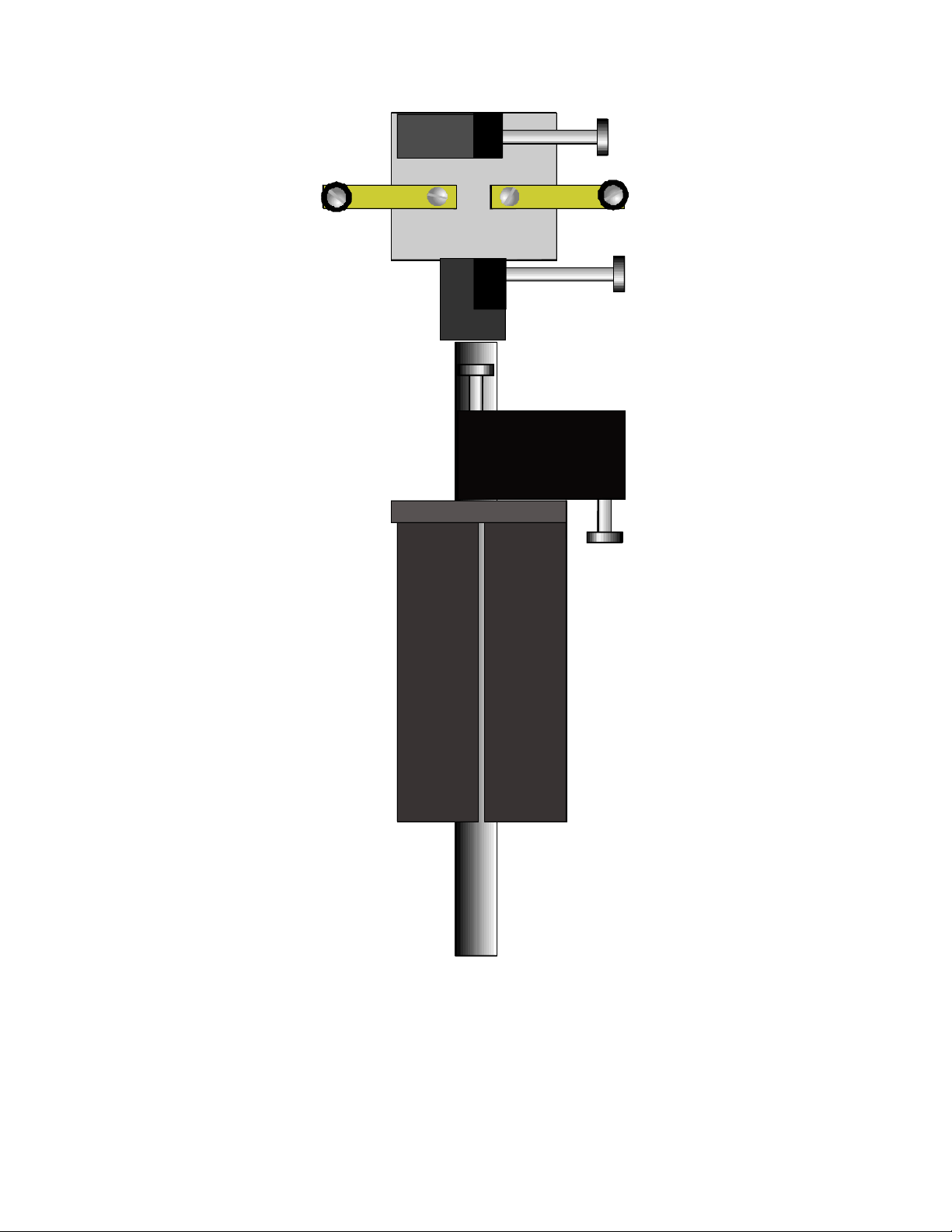
Figure 2-1. P-30 Mechanical Assembly.
P-30 MICROPIPETTE PULLER OPERATION MANUAL – REV. 3.10 (20100120)
Page 13

7
3.
3. IN STAL LATI O N
INS T ALLA TION
3.3.
INS T ALLA TIONINSTA L LAT I ON
3.1
3.1 Line Power (Mains)
Line Power (Mains)
3.13.1
Line Power (Mains)Line Power (Mains)
The power cord provided with the P-30 connects to the power entry module located on the
back of the unit (see diagram below). This module also includes the line fuse.
Figure 3-1. P-30 Cabinet (rear view).
Confirm that the Voltage Selector Switch on the Power Entry Module is set to the proper
value (110V a.c. or 220V a.c.). If it is not, turn the selector switch until the appropriate value
is lined up with the indicator. Note that the Line fuse differs for the two different line
is lined up with the indicator. Note that the Line fuse differs for the two different line
is lined up with the indicator. Note that the Line fuse differs for the two different line is lined up with the indicator. Note that the Line fuse differs for the two different line
vvvvoltages (see the Technical Specifications). If you have to change the voltage selector you
oltages (see the Technical Specifications). If you have to change the voltage selector you
oltages (see the Technical Specifications). If you have to change the voltage selector you oltages (see the Technical Specifications). If you have to change the voltage selector you
may also have to replace the fuse, otherwise your protection from fire and electric shock may
may also have to replace the fuse, otherwise your protection from fire and electric shock may
may also have to replace the fuse, otherwise your protection from fire and electric shock may may also have to replace the fuse, otherwise your protection from fire and electric shock may
be compromised.
be compromised.
be compromised.be compromised.
If it is not, turn the selector switch until the appropriate value
If it is not, turn the selector switch until the appropriate value If it is not, turn the selector switch until the appropriate value
Make certain that the Power Switch located on the front panel of the P-30 cabinet is turned
OFF. Plug the power cord provided with the P-30 into the Line Input socket on the Power
Entry Module and then to a power source of the appropriate voltage and frequency.
P-30 MICROPIPETTE PULLER OPERATION MANUAL – REV. 3.10 (20100120)
Page 14

8
(This page intentionally left blank.)
P-30 MICROPIPETTE PULLER OPERATION MANUAL – REV. 3.10 (20100120)
Page 15

9
4.
4. O P ERAT I NG I NSTR UCTI O
OPER A TIN G IN S TRU C TIO NS
4.4.
OPER A TIN G IN S TRU C TIOOPE R ATIN G IN STRU CTIO
4.1
4.1 First Time Use
First Time Use
4.14.1
First Time UseFirst Time Use
1. Load a piece of the supplied sample glass into puller as follows:
• Loosen the upper and lower clamping knobs.
• Place glass in V-groove in upper clamp; slide it downward until about 1 cm of glass
extends above the top clamp. Tighten upper clamp
• Pull lower clamp up until it no longer moves and tighten clamping knob.
2. Press the PULL button. The heating filament should turn on and the glass should
separate within 15 seconds.
4.2
4.2 General Operation
General Operation
4.24.2
General OperationGeneral Operation
The P-30 is quite simple to operate. However, common sense indicates that an instrument
that can melt glass must be used with some caution and a complete understanding of its
controls. Do not leave the puller powered on and unattended; particularly while a pullsequence is in progress. Pay extra attention when pulling pipettes after any control values
have been changed.
NS
NSN S
The following steps outline a basic pulling sequence. The pipette being pulled is hypothetical
(with respect to the settings mentioned) and is intended only as an example of the normal
pulling procedure. The pipette shapes and tip diameter obtained from a puller of this type
are dependent on the rate at which heat is added to the glass (rate of change of viscosity),
weight of the moving portion of the slide assembly, distance traveled during gravity pull
phase, and force of solenoid pull. When you have found settings that produce the desired
pipette, make note of the time it takes for the pull to take place and the distance being
traveled before the hard pull. The time for a pull is most important, particularly when
having to install a new filament. No two filaments are exactly alike with respect to their
resistance; thus, the heat setting may not be the same for two different filaments to supply
the same amount of heat. All other factors being unchanged (pull strength, glass size,
acceleration due to gravity, etc.), if the heat output of the new filament is adjusted to produce
a pull in the same amount of time as the previous filament the pipettes should be equivalent.
4.3
4.3 Pulling a Micropipette
Pulling a Micropipette
4.34.3
Pulling a MicropipettePulling a Micropipette
Turn instrument on, and make sure that the desired heat value has been selected. If one is
setting a heat value for the first time, then press PULL (no glass in puller) and increase the
HEAT control while watching the filament. If using a platinum filament, be sure the heat
value is initially set at a low value (e.g. 300 for a 1.5mm filament, 650 for a 3.0mm filament).
High heat values can destroy the platinum filaments. Because of the time constant of the
nichrome filament, allow a few moments to pass after making any changes to let the filament
stabilize at the new heat setting. When the filament glows at desired heat level, note the
selected value. Press RESET to turn off filament.
P-30 MICROPIPETTE PULLER OPERATION MANUAL – REV. 3.10 (20100120)
Page 16

10
Open upper glass clamp and insert glass capillary into jaws. Close down clamp on capillary
until glass is gripped lightly so glass can still slide. Slide capillary down through filament to
the point where the lower glass clamp can be raised up to grip lower end of capillary..
Tighten upper clamp and raise lower clamp over capillary. As glass capillaries may have a
slight curve to them, take care when inserting the capillary into the lower jaws. Tighten
lower glass clamp. The setting of the trip point is an important determinant of the size and
shape that will be obtained and will be covered below. Close front door and press PULL.
The following sequence takes place: 1) Filament turns on and glass is heated to softening
point. 2) As glass softens, lower glass clamp and slide bar descent under the influence of
gravity until the trip flag interrupts the optical switch. 3) The optical switch deactivates the
heat and activates the pull solenoid for approximately one second to complete pull.
Remove lower and upper pipettes.
4.4
4.4 Multicycle Pulling: Pulling a Patch
Multicycle Pulling: Pulling a Patch----Type Micropipette
4.44.4
Multicycle Pulling: Pulling a PatchMulticycle Pulling: Pulling a Patch
Type Micropipette
Type MicropipetteType Micropipette
Patch type pipettes are characteristically stubby with a large taper angle and relatively large
tips (> 1 micron). To construct this type of pipette, it is desirable to process the glass in
multiple heating cycles. The P-30 can be used for two-step pipette fabrication with the use of
the dual heat settings and the supplied Patch Block. The first of the two steps draws the
glass out without separating. The glass tube must then be manually repositioned so that the
drawn-out portion is again centered within the heating element. The second step then draws
the glass out until it separates to form a pipette.
4.4.1
4.4.1 Heat Settings
Heat Settings
4.4.14.4.1
Heat SettingsHeat Settings
HEAT 1 is used for the first step, and is generally set at a fairly high level (e.g. 750 for 3mm
platinum filament or 970 for nichrome filament). HEAT 2 is used for the second step, after
the glass has already been pulled once. HEAT 2 will normally be less than HEAT 1, and is
more critical than HEAT 1. The exact value for your particular application will have to be
determined on a trail and error basis.
4.4.2
4.4.2 Pull Settin
Pull Settingggg
4.4.24.4.2
Pull SettinPull Settin
Pull is normally set to zero for patch pipettes because the weight of the sliding components
provides the force that draws out the glass. If you desire, the solenoid plunger may be
disconnected from the slide assembly by loosening the set screw that attaches the cable to the
slide flag holder. This will decrease the weight by about 20%.
4.4.3
4.4.3 Trip Point
Trip Point Micrometer
4.4.34.4.3
Trip Point Trip Point
icrometer
icrometericrometer
The micrometer should be advanced so that the flag does not interrupt the optical switch
until the second step is complete. Because the solenoid is generally not used in forming
patch pipettes, the trip point system serves primarily as a means of turning off the heat.
While it is easy to reposition the trip point for each step, it is generally more convenient to
use the RESET button to turn the heat off after the first step. Thus, the optical switch will
normally be placed so that the flag passes through the switch in the second step. This will
cause the heat to turn off automatically at the end of the second step.
P-30 MICROPIPETTE PULLER OPERATION MANUAL – REV. 3.10 (20100120)
Page 17

11
4.4.4
4.4.4 Patch Block (spacer)
Patch Block (spacer)
4.4.44.4.4
Patch Block (spacer)Patch Block (spacer)
The two screws on the Patch Block are provided so that the block can act as two adjustable
spacers. The 10/32 cap head screws supplied accept a 5/32 hex key wrench; the thumbnuts
are used to lock the screws in position. The thumbnuts are different colors so you can
differentiate Spacer 1 versus Spacer 2. One spacer is needed to limit the draw of the first pull
cycle. The second spacer is needed to reposition the glass within the heating filament prior
to pulling the glass apart in the second step. The position of the two screws in the Patch
Block will need to be determined empirically.
4.5
4.5 Patch Pipette Pull Sequence
Patch Pipette Pull Sequence
4.54.5
Patch Pipette Pull SequencePatch Pipette Pull Sequence
4.5.1
4.5.1 First cycle
First cycle
4.5.14.5.1
First cycleFirst cycle
Set the HEAT switch to HEAT 1 and load capillary. Place the Patch Block so that is sits on
the top of the bearing block behind the slide bar as show in Figure 4-1. The head of the
screw will act to stop the slide mechanism by hitting the underside of the lower slide. The
length of the first pull will be determined by the space between the top of the Patch Block
screw and the bottom of the lower glass clamp assembly. Press PULL, wait until the slide
drops onto the screw and then press RESET. Remove Patch Block.
4.5.2
4.5.2 Second cycle
Second cycle
4.5.24.5.2
Second cycleSecond cycle
Since the heating filament is fixed in position and the glass is drawn in one direction, it
follows that the portion of the glass that has been reduced in size will not be centered in the
filament at the end of the first step. Reposition the glass by first loosening the upper glass
clamp, lifting the lower slide assembly until the glass is re-centered within the filament, and
then re-tightening the upper clamp. To consistently re-center the glass, insert the Patch
Block (second screw) between the top of the bearing block and the bottom of the lower glass
clamp. Tighten the upper glass clamp while the lower glass clamp rests on the head of the
screw. Remove the Patch Block. Set the HEAT switch to HEAT 2, and press PULL. The
pipette should separate during this cycle, and the heat will automatically turn off.
P-30 MICROPIPETTE PULLER OPERATION MANUAL – REV. 3.10 (20100120)
Page 18
12
Figure 4-1. Patch Block Placement.
4.6
4.6 Controls Adjustment
Controls Adjustment
4.64.6
Controls AdjustmentControls Adjustment
In order to make the pipettes you desire, you first must understand the effects of the controls
and the various parameters on the glass. The general rule-of-thumb is that both an increase
in the heat and an increase in the pull strength will produce smaller tips and longer tapers.
P-30 MICROPIPETTE PULLER OPERATION MANUAL – REV. 3.10 (20100120)
Page 19

13
Thus, to obtain the smallest possible tips, you would use a high heat setting (e.g. 980 for
nichrome filament and 750 for 3mm platinum filament) and a pull setting above 950.
The setting of the optical switch is more complicated. Your P-30 optical switch was set at 2.5
to produce fine micropipettes with 1mm O.D. x .5mm I.D. borosilicate glass when it was
shipped to you. As the optical switch is moved lower, the distance traveled in the weak pull
will increase. The longer the weak pull, the more the glass is attenuated in diameter. This
will influence the rate at which the glass can be drawn-out during the subsequent hard pull
as well as the rate of cooling during that pull. In addition, the length of the weak pull will
determine the position of the solenoid plunger in the solenoid coil, which in turn will alter
the force developed by the solenoid. It follows that some trial and error adjustment of the
optical switch may be required to obtain a particular result. If the weak pull is too short you
may find that the tips are quite large. If the weak pull is too long the pipettes may form long
wispy threads rather than tips.
P-30 MICROPIPETTE PULLER OPERATION MANUAL – REV. 3.10 (20100120)
Page 20

14
(This page intentionally left blank.)
P-30 MICROPIPETTE PULLER OPERATION MANUAL – REV. 3.10 (20100120)
Page 21

15
.5-1mm
5.
5. MA INT E NANC E
MAIN TENA NCE
5.5.
MAIN TENA NCEMAIN TENAN CE
5.1
5.1 Filament Replacement
Filament Replacement
5.15.1
Filament ReplacementFilament Replacement
Platinum filament life will vary with several factors; operation temperature, frequency of
use, and the amount of care taken to avoid damage. Filament deterioration becomes more
rapid at higher operating temperatures, so it is good practice to keep the heating current as
low as possible, consistent with forming tips of the desired size and configuration.
Significant deterioration of the filament is indicated by the appearance of small holes. These
holes raise the resistance of the filament and necessitate higher HEAT setting to produce the
same heat output.
Platinum trough filaments for the P-30 are available in three widths: 1.5mm, 2.0m and
3.0mm. Heat delivery to the glass is partially a function of filament width. Thus, both the
length of an electrode and the tip diameter will be affected by the filament width. A 3.0mm
wide filament will tend to produce longer pipettes and be capable of producing smaller tip
diameters. The 1.5mm wide filament will produce shorter pipette, but cannot be used to pull
as fine a tip as the wider filament.
To replace the filament, first loosen the thumbscrews that clamp the filament in place.
Remove the old filament. The sides of the new filament should be relatively parallel or
slightly less than parallel as illustrated in Figure 5-1. Grasp the new filament with a pair of
forceps and place the filament wings between the clamping jaws. Center the filament
relative to a piece of glass loaded in the upper glass clamp. Tighten the thumbnuts.
The entire heater block assembly is spring loaded to allow you to adjust the
forward/backward position of the platinum filament relative to a piece of glass. The back of
the filament should be approximately 0.5 mm to 1 mm away from the glass tubing (Figure
5-1). To move the back of the filament towards you, loosen the two Allen head screws located
on the black nylon block just above and below the brass clamp assembly. The heater
assembly will slide forward on the guide pins until movement is restricted by the screws. To
move the filament away from you, simply turn the Allen head screws clockwise an equal
amount until you have attained the desired filament position.
Figure 5-1. Top view of platinum filament glass.
5.2
5.2 Lubrication
Lubrication
5.25.2
Lubrication Lubrication
The slide bar should occasionally be wiped down with a light oil to protect it from corrosion.
Note that materials such as 3-in-1 oil are not sutiable as they leave a residue which can
“gum-up” the slide bar and bushings.
No other P-30 components require lubrication.
P-30 MICROPIPETTE PULLER OPERATION MANUAL – REV. 3.10 (20100120)
Page 22

16
5.3
5.3 Rubber Pads on Clamps
Rubber Pads on Clamps
5.35.3
Rubber Pads on ClampsRubber Pads on Clamps
The rubber pads attached to the upper and lower glass clamps can wear down to the extent
that it becomes difficult to adequately clamp the glass in place. If this should occur, please
contact the technical support staff at Sutter and request some replacement pads. The pads
can be bonded to the clamps with cyanoacrylate (“super glue”) or a similar bonding material.
5.4
5.4 Troubleshooting
Troubleshooting
5.45.4
TroubleshootingTroubleshooting
We have provided this section as an aid for troubleshooting some of the common electronic
problems of the P-30. Discussions of circuit board level troubleshooting and circuit board
schematics have intentionally been left out. Any work done with the cabinet cover removed
requires very careful attention to the hazardous voltages that exist inside cabinet, and should
therefore be performed by qualified service personnel only. We ask that you please contact
Sutter for further information and advice prior to removing the cabinet. Instructions and
circuit schematics can be supplied upon request.
1. Pilot light not on, no pull or heat:
Pilot light not on, no pull or heat:
Pilot light not on, no pull or heat:Pilot light not on, no pull or heat:
Check and make sure that the power cord is connected to a working circuit and that the
power has been switched on. If the power is good, disconnect the power cord and check to
see if the fuse on the rear of the cabinet has blown. If the fuse is good, put it back in
place and reconnect the power. If the unit seemed to turn off during a prolonged pull, the
internal protective thermostat may have opened. The thermostat will automatically reset
if the instrument is turned off for about ½ hour. If the fuse has blown, suspect failed
power MOSFET transistor(s) in the constant current power supplies (see below). Contact
Sutter for MOSFET replacement instructions.
3. Pilot light on, no heat:
Pilot light on, no heat:
Pilot light on, no heat:Pilot light on, no heat:
If the pilot light is on, there is no need to check the fuse or power connections, although
you may wish to check for low line voltage. If the heat fails to turn on when the PULL
button is pressed, make sure that there is a reasonable heat value entered and that the
HEAT 1/HEAT2 switch is set to select the desired value. Check that the optical switch is
not interrupted by the flag. With no glass loaded, press PULL and carefully lift the slide
unit until the flag interrupts the optical switch. This should activate the pull, which will
forcefully draw the slide bar down. If the pull is not activated, refer to (3).
If pull is working, the basic logic circuits and the power supplies are functional. Check to
make sure the thumbnuts that hold the filament in place are tight. Inspect the filament
for a possible break. If you have a nichrome assembly, check the screws that hold the
binding posts to the copper straps and the screws that secure those straps to insure that
good contact is made throughout. Further checks require removal of the cover portion of
the cabinet. Please contact the technical support staff at Sutter if further
troubleshooting is required.
4. Pilot light on, no heat or pull:
Pilot light on, no heat or pull:
Pilot light on, no heat or pull:Pilot light on, no heat or pull:
These symptoms suggest one of three faults: 1) the 40-volt power supply has failed; 2) the
2.5-volt reference has failed; and, 3) the logic circuits fail to correctly enable the heat and
pull. To check any of these faults requires that the cabinet be removed from the puller.
Please contact Sutter prior to troubleshooting these faults. A circuit diagram and
instructions can be supplied if necessary.
P-30 MICROPIPETTE PULLER OPERATION MANUAL – REV. 3.10 (20100120)
Page 23

17
5. Pilot light on, heat works, no pull:
Pilot light on, heat works, no pull:
Pilot light on, heat works, no pull:Pilot light on, heat works, no pull:
If the heat does not turn off when the optical switch is interrupted, suspect the optical
switch. If the heat does turn off, but the pull never turns on, the logic and constant
current circuits need to be checked. Please contact Sutter if this is required.
P-30 MICROPIPETTE PULLER OPERATION MANUAL – REV. 3.10 (20100120)
Page 24

18
(This page intentionally left blank.)
P-30 MICROPIPETTE PULLER OPERATION MANUAL – REV. 3.10 (20100120)
Page 25

19
APP E NDIX A.
APP E NDIX A. L IMIT E D WA RRAN TY
APP E NDIX A.A PPEN D IX A .
LIM I TED W ARRA NTY
LIM I TED W ARRA NTYLIM I TED W ARRA NTY
Sutter Instrument Company, a division of Sutter Instrument Corporation, limits the
warranty on this instrument to repair or replacement of defective components for one year
after the date of shipment, provided the instrument has been operated in accordance with
the instructions outlined in the instruction manual.
Abuse, misuse or unauthorized repairs will void this warranty.
Limited warranty work is performed only at the factory, and the cost of shipment both ways
is borne by the user.
This instrument is designed to pull glass pipettes for use on animal tissues. It is not
intended for use, and should not be used, in human experimentation or applied to humans in
any way.
The limited warranty is as stated above and no implied or inferred liability for direct or
consequential damages is intended.
P-30 MICROPIPETTE PULLER OPERATION MANUAL – REV. 3.10 (20100120)
Page 26

20
(This page intentionally blank.)
P-30 MICROPIPETTE PULLER OPERATION MANUAL – REV. 3.10 (20100120)
Page 27

21
APP E NDIX B.
APP E NDIX B. A C CES S ORIE S
APP E NDIX B.A PPE N DIX B.
The following accessories are available for the P-30 Micropipette Puller. See
http://www.sutter.com for more detail and availability P-30 accessories, and for part numbers
not expressed in the following list.
Nichrome filament block assembly (P
Nichrome filament block assembly (P----30
Nichrome filament block assembly (PNichrome filament block assembly (P
Platinum/iridium filament block assembly (P
Platinum/iridium filament block assembly (P----30
Platinum/iridium filament block assembly (PPlatinum/iridium filament block assembly (P
Pipette storage box 4 3/4 x 3 5/8 x 3/4 inches (BX10)
Pipette storage box 4 3/4 x 3 5/8 x 3/4 inches (BX10)
Pipette storage box 4 3/4 x 3 5/8 x 3/4 inches (BX10)Pipette storage box 4 3/4 x 3 5/8 x 3/4 inches (BX10)
Pipette storage box
Pipette storage box ---- long 7 x 3 5/8 x 3/4 inches (BX20)
Pipette storage box Pipette storage box
ACC E SSO R IES
ACC E SSO R IESAC C ESSO RIES
30----NFL/M)
NFL/M)
3030
NFL/M)NFL/M)
30----PFL/M)
3030
long 7 x 3 5/8 x 3/4 inches (BX20)
long 7 x 3 5/8 x 3/4 inches (BX20) long 7 x 3 5/8 x 3/4 inches (BX20)
PFL/M)
PFL/M)PFL/M)
BV
BV----10 Microelectrode Beveler (
10 Microelectrode Beveler (BV
BVBV
10 Microelectrode Beveler (10 Microelectrode Beveler (
Glass Capillary Tubing
Glass Capillary Tubing
Glass Capillary TubingGlass Capillary Tubing
Puller Filaments
Puller Filaments
Puller FilamentsPuller Filaments
BV----10)
10)
BVBV
10)10)
P-30 MICROPIPETTE PULLER OPERATION MANUAL – REV. 3.10 (20100120)
Page 28

22
(This page intentionally blank.)
P-30 MICROPIPETTE PULLER OPERATION MANUAL – REV. 3.10 (20100120)
Page 29
23
APP E NDIX C.
APP E NDIX C. FU SE R EPLA C EME N T
APP E NDIX C.APPEND I X C .
FUS E REP L ACE MENT
FUS E REP L ACE MENTFUS E REP L ACE MENT
In the event that the puller fails to power up when the power switch is turned on, check the
line power fuse to see if it has blown. The fuse is located in the fuse holder on the power
entry module on the back of the P-30. To remove the fuse holder first unplug the power cord
from the power entry module. This will reveal a slot just under the edge of the fuse holder.
Use a screwdriver to pry the holder straight out of the power entry module.
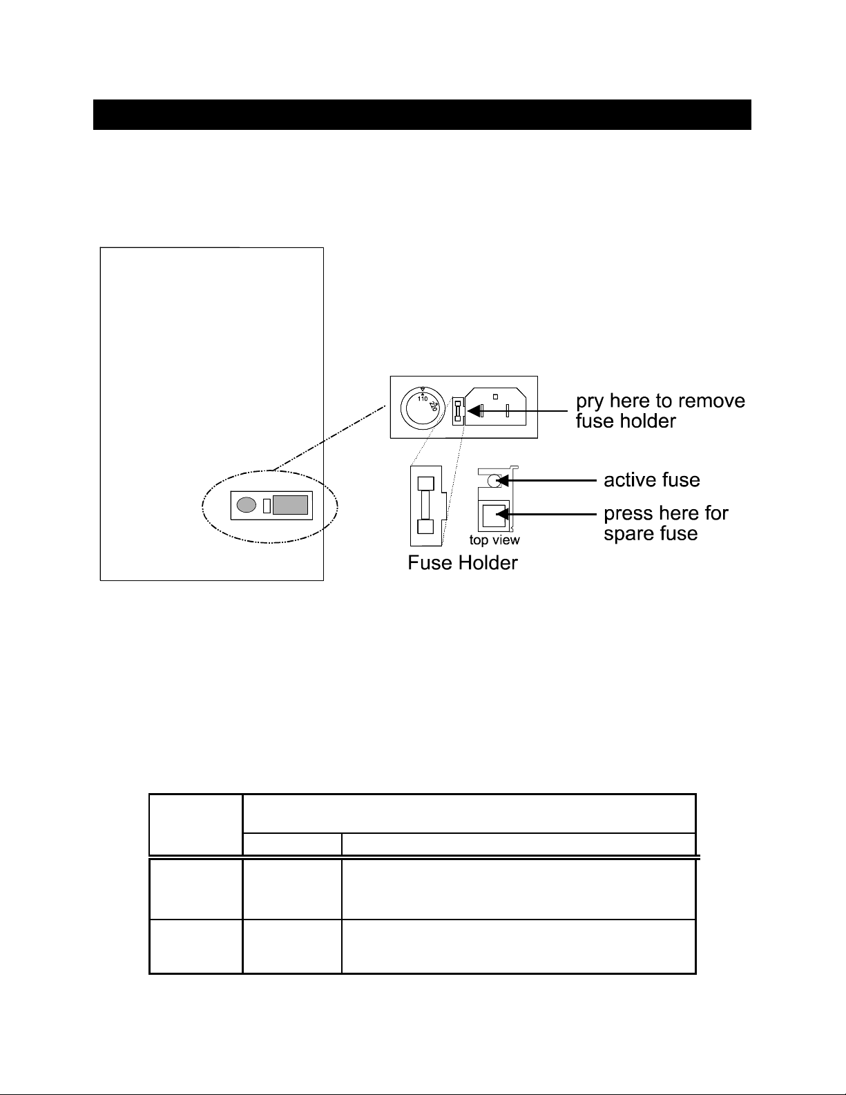
Figure C-1. Fuse holder.
The fuse that is readily visible in the fuse holder when you take it out is the one that is
“active” when the holder is installed. A spare fuse is also stored within the fuse holder. It is
concealed in a compartment as shown in Figure C-1. To remove the spare fuse, press down
on the end of the compartment and push it out of the other end. The old fuse can serve as a
convenient tool for pushing the spare fuse compartment out. Replace the active fuse with the
spare and re-install the fuse holder and power cord. If the P-30 fails to power up with the
new fuse installed, call Sutter Instrument technical support personnel for assistance.
Table C-1. Mains fuse type and ratings.
Fuse
Mains Voltage
Mains Voltage
Mains VoltageMains Voltage
Setting
Setting
SettingSetting
“110”
(100 – 120
VAC)
“220”
(200 – 240
VAC)
(Type: Time Delay, 5mm x 20mm, glass tube)
(Type: Time Delay, 5mm x 20mm, glass tube)
(Type: Time Delay, 5mm x 20mm, glass tube)(Type: Time Delay, 5mm x 20mm, glass tube)
Rating
Rating Manufacturer Examples
RatingRating
2A, 250V
(Time Delay)
T1.25A,
250V
Bussmann: GMC-2A, GMC-2-R (RoHS), GDC-2A, or
S506-2A (RoHS)
Littelfuse: 239 002 or 239.002.P (RoHS)
Bussmann: GDC-1.25A or S506-1.25R (RoHS)
Littelfuse: 218 1.25 or 218 1.25P (RoHS)
Fuse
FuseFuse
Manufacturer Examples
Manufacturer ExamplesManufacturer Examples
P-30 MICROPIPETTE PULLER OPERATION MANUAL – REV. 3.10 (20100120)
Page 30

24
(This page intentionally blank.)
P-30 MICROPIPETTE PULLER OPERATION MANUAL – REV. 3.10 (20100120)
Page 31

25
APP E NDIX D.
Mains Voltage
Mains Voltage Mains Voltage
Mains Voltage
APP E NDIX D. T E CHN I CAL SPEC I FICA T
APP E NDIX D.APPEN DIX D.
TEC H NICA L SP E CIF I CAT IONS
TEC H NICA L SP E CIF I CATTE CHNI CAL SPEC I FICA T
ION S
ION SION S
Dimensions (H x W x D):
Dimensions (H x W x D): 18 x 10 x 9 in (46 x
Dimensions (H x W x D):Dimensions (H x W x D):
Weight:
Weight: 35 lb.
Weight:Weight:
Electrical:
Electrical:
Electrical:Electrical:
Mains voltage
Mains voltage 110
Mains voltageMains voltage
Maximum power consumption
Maximum power consumption 180 VA
Maximum power consumptionMaximum power consumption
Mains fuse (rear of cabinet)
Mains fuse (rear of cabinet)
Mains fuse (rear of cabinet) Mains fuse (rear of cabinet)
Table D-1. Mains fuse type and ratings.
(Type: Time Delay, 5mm x 20mm, glass tube)
Setting
Setting
SettingSetting
“110”
(100 – 120
VAC)
“220”
(200 – 240
VAC)
Rating
Rating Manufacture
RatingRating
2A, 250V
(Time Delay)
T1.25A,
250V
(Type: Time Delay, 5mm x 20mm, glass tube)
(Type: Time Delay, 5mm x 20mm, glass tube)(Type: Time Delay, 5mm x 20mm, glass tube)
Bussmann: GMC-2A, GMC-2-R (RoHS), GDC-2A, or
S506-2A (RoHS)
Littelfuse: 239 002 or 239.002.P (RoHS)
Bussmann: GDC-1.25A or S506-1.25R (RoHS)
Littelfuse: 218 1.25 or 218 1.25P (RoHS)
18 x 10 x 9 in (46 x 25 x 23 cm)
18 x 10 x 9 in (46 x18 x 10 x 9 in (46 x
35 lb. (16
35 lb. 35 lb.
110----120 V, 60 Hz
110110
220
220----240 V, 50 Hz
220220
180 VA
180 VA180 VA
(16 kg)
kg)
(16(16
kg) kg)
120 V, 60 Hz
120 V, 60 Hz120 V, 60 Hz
240 V, 50 Hz
240 V, 50 Hz240 V, 50 Hz
Fuse
Fuse
FuseFuse
Manufacturer Examples
ManufactureManufacture
Power cord
Power cord 10A, 250V, with safety ground plug
Power cordPower cord
10A, 250V, with safety ground plug
10A, 250V, with safety ground plug10A, 250V, with safety ground plug
25 x 23 cm)
25 x 23 cm) 25 x 23 cm)
r Examples
r Examplesr Examples
P-30 MICROPIPETTE PULLER OPERATION MANUAL – REV. 3.10 (20100120)
Page 32

26
(This page intentionally left blank.)
P-30 MICROPIPETTE PULLER OPERATION MANUAL – REV. 3.10 (20100120)
Page 33

27
IND E X
IND E X
IND E XIN DE X
AAAA
MMMM
accessories ..............................................................23
CCCC
controls
front panel, lower.................................................5
front panel, upper................................................5
controls adjustment...............................................14
DDDD
dimensions..............................................................29
of glass ..................................................................1
disclaimer ............................................................... iii
FFFF
first-time use..........................................................11
front panel................................................................5
fuse
holder..................................................................25
location ...............................................................25
spare....................................................................25
fuse replacement....................................................25
fuses, replacement
mains................................................................... iii
mains...................................................................29
GGGG
glass
dimensions............................................................1
glassware
loading ................................................................11
precautions..........................................................iv
specifications........................................................1
HHHH
heat
definition ..............................................................5
IIII
ID...............................................................................1
KKKK
keys
PULL....................................................................5
reset.......................................................................5
LLLL
line power (mains)...................................................9
mains.........................................................................9
fuses .................................................................... iii
fuses ....................................................................29
power consumption ...........................................29
power cord..........................................................29
voltage.................................................................29
maintenance...........................................................17
filament replacement ........................................17
lubrication ..........................................................17
rubber pads on clamps ......................................18
mechanical description
patch block ...........................................................7
pull solenoid .........................................................7
slide assembly
bushing blocks and guide bushings ...............7
filament assembly............................................6
guide flag holder ..............................................7
lower (moving) glass clamp assembly............6
side bar..............................................................6
trip flag holder .................................................7
upper (stationary) glass clamp assembly.......6
slide assembly.......................................................6
mechanical description (puller anatomy)..............6
NNNN
notes
user......................................................................33
OOOO
OD.............................................................................1
operation.................................................................11
heat settings.......................................................12
multicycle pulling (pulling a patch-type
micropipette)..................................................12
patch block (spacer)...........................................13
patch pipette pull sequence ..............................13
first cycle.........................................................13
second cycle....................................................13
precautions..........................................................iv
pull settings........................................................12
pulling a micropipette .......................................11
trip point micrometer........................................12
PPPP
power
consumption.......................................................29
power cord
mains...................................................................29
P-30 MICROPIPETTE PULLER OPERATION MANUAL – REV. 3.10 (20100120)
Page 34

28
power entry module...............................................25
power switch ............................................................9
pull
definition ..............................................................6
puller anatomy.........................................................6
SSSS
safety warnings...................................................... iii
avoiding fire/shock hazard................................ iii
slide assembly ..........................................................6
TTTT
technical specifications..........................................29
technical support .....................................................1
troubleshooting......................................................18
UUUU
unpacking.................................................................5
VVVV
voltage
mains...................................................................29
voltage selector switch.............................................9
WWWW
warranty.................................................................21
weight .....................................................................29
P-30 MICROPIPETTE PULLER OPERATION MANUAL – REV. 3.10 (20100120)
Page 35

29
NOTES
NOTES
NOTESNOTES
P-30 MICROPIPETTE PULLER OPERATION MANUAL – REV. 3.10 (20100120)
Page 36

30
NOTES
NOTES
NOTESNOTES
P-30 MICROPIPETTE PULLER OPERATION MANUAL – REV. 3.10 (20100120)
 Loading...