

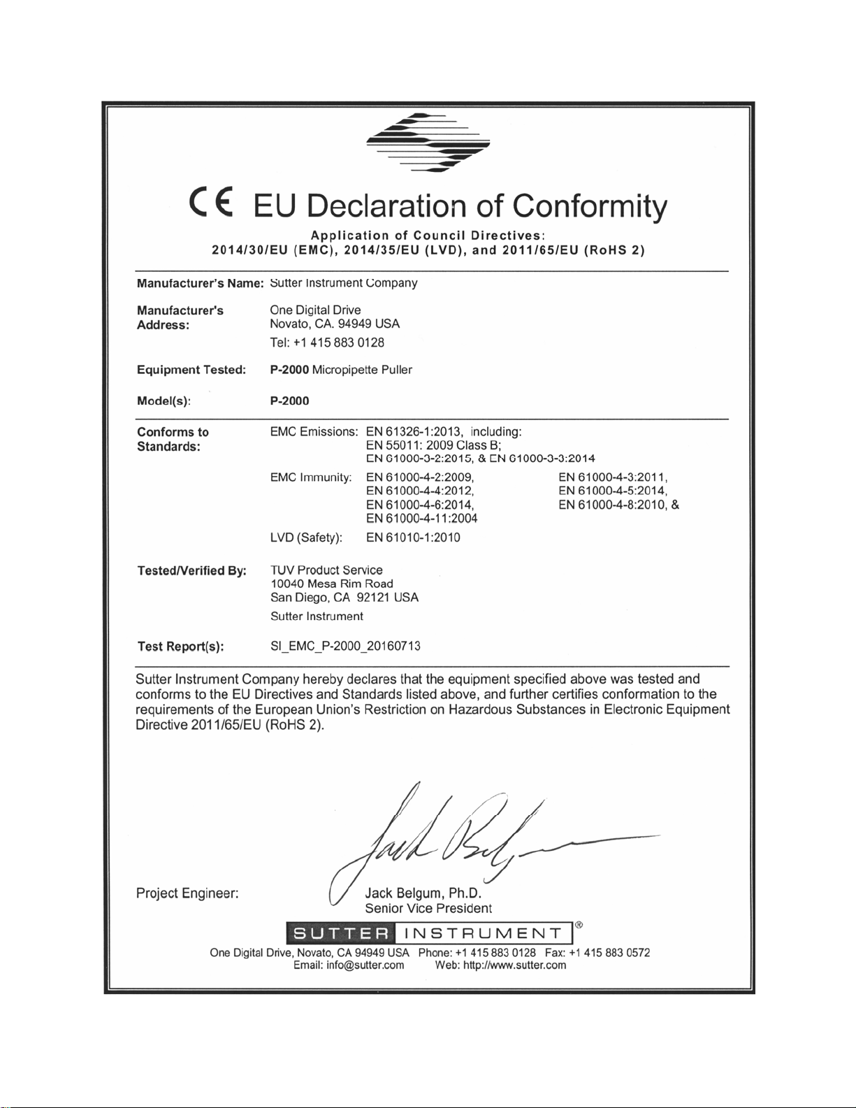
Page 1

P-2000
Laser-Based Micropipette
Puller System
Operation Manual
Rev. 2.4c ( 20160412)
One Digital Drive
Novato, CA 94949
Voice: 415-883-0128 Web: www.sutter.com
Fax: 415-883-0572 Email: info@sutter.com
Page 2

ii
Copyright © 2016 Sutter Instrument Company. All Rights Reserved.
P-2000 MICROPIPETTE PULLER OPERATION MANUAL -– REV. 2.4C (20160412)
Page 3
Page 4

Page 5
DISCLAIMER
The pipette puller Model P-2000 is designed for the specific use of creating micropipettes,
electrospray/nanospray emitters and optic fibers. No other use is recommended.
This instrument is designed for use in a laboratory environment. It is not intended, nor
should it be used in human experimentation or applied to humans in any way. This is
not a medical device.
Do not open or attempt to repair the instrument. Extreme heat and high voltages are
present and could cause injury.
Do not allow unauthorized and/or untrained operative to use this device.
Any misuse will be the sole responsibility of the user/owner, and Sutter Instrument
Company assumes no implied or inferred liability for direct or consequential damages
from this instrument if it is operated or used in any way other than for which it is
designed.
LASER SAFETY WARNING
iii
The P-2000 Micropipette Puller is a CO
laser based micropipette puller and as such its
2
design and construction are regulated; in the US by the FDA’s Bureau of Radiological
Health (CDRH), in the European Community by the harmonized standard EN608251:1997, and in most other countries by the relevant laser safety documents usually based
on IEC60825-1:1997.
The P-2000 Puller as manufactured is classified as a Class I laser product under each of
the above mentioned laser safety standards. This means that it can be operated safely as
shipped without the need for additional safety measures.
The P-2000 Puller contains a 20W Class IV CO
laser with a
2
3.5mm diameter beam (4mR divergence). A number of safety shields, enclosures and
redundant interlocks have been built into the P-2000 to protect the user from any
radiation exposure. UNDER NO CIRCUMSTANCES SHOULD THE SAFETY
ENCLOSURES BE REMOVED OR THE INTERLOCKS DEFEATED. DOING SO
COULD INJURE THE OPERATOR OR PASSERS BY IN A SERIOUS MANNER. This
laser emits invisible radiation that can inflict severe burns to those exposed to the beam,
even momentarily.
Regulations require any injury by or exposure to the contained radiation of this
device be reported to Sutter Instrument Company immediately.
P-2000 MICROPIPETTE PULLER OPERATION MANUAL -– REV. 2.4C (20160412)
Page 6

v
i
(Figure: Location of Laser Beam and "LASER ON" Warning Light.)
SAFETY WARNING LABELS
The following Safety labels are attached to the P-2000 when shipped to you:
(Figure. Safety Labels on top of base plate.)
(Figure: Safety Label on the bottom of the Base Plate.)
P-2000 MICROPIPETTE PULLER OPERATION MANUAL -– REV. 2.4C (20160412)
Page 7

v
GENERAL SAFETY WARNINGS AND PRECAUTIONS
WARNING: Use of controls or adjustments or performance of procedures other
than those specified herein may result in hazardous radiation exposure.
Electrical
Operate the P-2000 using 110-120 V AC, 60 Hz, or 220-240 V AC., 50 Hz line voltage.
This instrument is designed for connection to a standard laboratory power outlet
(Overvoltage Category II), and because it is a microprocessor--controlled device, it should
be accorded the same system wiring precautions as any 'computer type' system. A surge
protector and power regulator are recommended.
Fuse Replacement: Replace fuse only with the same type and rating as indicated in
the following table.
(Table. Fuse specifications and ratings according to mains power.)
Mains
Voltage
Setting
“110”
(100 – 120
VAC)
“220”
(200 – 240
VAC)
Rating Manufacturer Examples
5A, 125 or 250V
(Time Delay)
T3.15A, 250V Bussmann: GDC-3.15A or S506-3.15-R (RoHS)
(Type: Time Delay, 5mm x 20mm, glass tube)
Bussmann: GMC-5A, GDC-5A or S506-5-R (RoHS)
Littelfuse: 239 005 (RoHS)
Littelfuse: 218 3.15 (RoHS)
Fuse
A spare fuse is provided, which is located in the power input module. Please refer to the
Fuse Replacement appendix located in the end portion of this manual.
Avoiding Electrical Shock and Fire-related Injury
WARNING: Always use the grounded power supply cord set provided to connect the
unit to a grounded outlet (3-prong). This is required to protect you from injury in the
event that an electrical hazard occurs.
CAUTION: Before operating the instrument, check that the instrument’s voltage
rating corresponds to the supply voltage. The voltage rating can be found on the power
entry module on the rear of the instrument.
CAUTION: Before making electrical connections, ensure that the instrument is
switched off.
CAUTION: Do not disassemble the unit. All servicing of this unit must be
performed at Sutter Instrument Company since appropriate laser safety training is
required for all service personnel. Please contact Sutter Instrument Technical Support
in the event servicing is required.
P-2000 MICROPIPETTE PULLER OPERATION MANUAL -– REV. 2.4C (20160412)
Page 8

vi
CAUTION: To prevent fire or shock hazard do not expose the unit to rain or
moisture.
WARNING: To avoid burns do not touch the heated ends of glass pipettes that have
been pulled.
Back Injury Prevention
WARNING: To avoid injuring your back or limbs it is recommended that you do not
attempt to lift this instrument by yourself. The P-2000 Micropipette Puller weighs in excess
of 36.4 kg (over 80 lb) and should be moved by TWO (2) people and placed on a cart or trolley
of sufficient robustness to support the weight.
Operational
Failure to comply with any of the following precautions may damage this device.
This instrument is designed for operation in a laboratory environment (Pollution Degree
I).
This unit was not designed for operation at altitudes above 2000 meters nor was it tested
for safety above 2000 meters.
Operate only in a location where there is a free flow of fresh air on all sides. The
fan draws air in and exhausts it through vents on the back of the instrument. NEVER
ALLOW THE FREE FLOW OF AIR TO BE RESTRICTED.
Since the P-2000 Puller is a microprocessor-controlled device, it should be accorded the
same system wiring precautions as any “computer type” system. If microprocessor based
systems in the lab require line surge protection for proper operation, then the same
protection should be provided for the P-2000.
Handling Micropipettes
Failure to comply with any of the following precautions may result in injury to the users of
this device as well as those working in the general area near the device.
The micropipettes created using this instrument are very sharp and relatively fragile.
Contact with the pulled micropipette tips, therefore, should be avoided to prevent
accidentally impaling yourself.
Always dispose of micropipettes by placing them into a well-marked, spill-proof “sharps”
container.
Use only with glassware recommended by Sutter Instrument Company in the following
sections of this manual.
P-2000 MICROPIPETTE PULLER OPERATION MANUAL -– REV. 2.4C (20160412)
Page 9

vii
TABLE OF CONTENTS
DISCLAIMER .........................................................................................................................................iii
LASER SAFETY WARNING ................................................................................................................iii
SAFETY WARNING LABELS..............................................................................................................iv
GENERAL SAFETY WARNINGS AND PRECAUTIONS .................................................................v
Electrical ..................................................................................................................................................v
Avoiding Electrical Shock and Fire-related Injury.............................................................................. v
Back Injury Prevention .........................................................................................................................vi
Operational .............................................................................................................................................vi
Handling Micropipettes.........................................................................................................................vi
1. GENERAL INFORMATION..............................................................................................................1
1.1 Introduction....................................................................................................................................... 1
1.2 Technical Support.............................................................................................................................1
1.3 Information Labels ...........................................................................................................................2
1.4 Glassware Specifications.................................................................................................................. 2
1.5 Mechanical Description (Puller Anatomy)..................................................................................... 2
1.5.1 Some Basic Information ............................................................................................................2
1.5.2 Upper Cable Pulley Assembly................................................................................................... 3
1.5.3 Retro-Mirror Assembly..............................................................................................................4
1.5.4 Optical Pathway .........................................................................................................................5
1.5.5 Cabinet ........................................................................................................................................8
2. INSTALLATION.................................................................................................................................9
2.1 Unpacking.......................................................................................................................................... 9
2.2 Setting Up..........................................................................................................................................9
2.2.1 Removing the Shipping Screw.................................................................................................. 9
2.2.2 Line Power (Mains)..................................................................................................................10
3. OPERATIONS...................................................................................................................................13
3.1 First Time Use ................................................................................................................................13
3.2 Front Panel......................................................................................................................................15
3.2.1 Controls .....................................................................................................................................15
3.2.2 Display....................................................................................................................................... 16
3.3 Programs..........................................................................................................................................18
3.3.1 Program Structure...................................................................................................................18
3.3.2 Cycle Parameters .....................................................................................................................18
3.4 Pull Cycle .........................................................................................................................................20
3.4.1 Default Configuration.............................................................................................................. 21
3.4.2 Selecting a Program [0 to 99]..................................................................................................22
3.4.3 Viewing a Program [NEXT] / [LAST]....................................................................................23
3.4.4 Clearing a Program from Memory [CLR] .............................................................................23
3.4.5 Editing a Program....................................................................................................................24
3.4.5.1 Entering a new program................................................................................................... 24
3.4.5.2 Editing an Existing Program ...........................................................................................24
3.5 Software Control Functions...........................................................................................................25
P-2000 MICROPIPETTE PULLER OPERATION MANUAL -– REV. 2.4C (20160412)
Page 10

viii
3.5.1 RAMP TEST <1> ...................................................................................................................25
3.5.2 WRITE-PROTECT THIS PROG[RAM] <2>...................................................................... 26
3.5.3 RESET TIME AND DATE <3>............................................................................................27
3.5.4 MEMORY TEST <4>.............................................................................................................27
3.5.5 COPY A PROGRAM <5> ......................................................................................................28
3.6 Pulling Pipettes...............................................................................................................................29
3.6.1 Procedures ................................................................................................................................29
3.6.1.1 Looping ...............................................................................................................................29
3.6.1.2 Pull Results ........................................................................................................................30
3.6.2 Notes on Program Operation..................................................................................................31
3.6.2.1 HEAT ON...........................................................................................................................31
3.6.2.2 Program Memory ..............................................................................................................32
3.7 Parameter Adjustment...................................................................................................................32
3.7.1 General Information ................................................................................................................32
3.7.2 Micropipette/Microinjection Needle Fabrication..................................................................32
3.7.2.1 Programs ............................................................................................................................32
3.7.2.2 Selecting Program Parameters........................................................................................32
3.7.2.3 Glass Selection ...................................................................................................................34
3.7.2.4 Glass-specific Parameter Adjustment .............................................................................34
3.7.2.5 Sample Programs (for Quartz glass) ...............................................................................35
3.7.3 Patch Pipette Fabrication .......................................................................................................36
3.7.3.1 Programs ............................................................................................................................36
3.7.3.2 Selecting Program Values ................................................................................................36
3.7.3.3 Glass Selection ...................................................................................................................37
3.7.3.4 Glass-Specific Parameter Adjustment ............................................................................38
3.7.3.5 Optical System Adjustments ............................................................................................ 38
3.7.3.6 Suggested Practices...........................................................................................................39
3.7.4 Optic Fiber Fabrication ...........................................................................................................39
3.7.4.1 Fiber Preparation ..............................................................................................................39
3.7.4.2 Programs ............................................................................................................................39
3.7.4.3 Selecting Program Parameters........................................................................................39
3.7.5 Electrospray/Nanospray Tip Fabrication ..............................................................................40
3.7.5.1 Glass Preparation.............................................................................................................. 40
3.7.5.2 Programs ............................................................................................................................40
3.7.5.3 Selecting Program Parameters........................................................................................41
3.7.6 Technical Tips ..........................................................................................................................41
3.7.6.1 Maintaining Pipette Wall Thickness of Quartz Glass...................................................41
4. APPLICATIONS AND TECHNIQUES ..........................................................................................43
4.1 Pulling Very Short Micropipettes .................................................................................................43
4.2 Pulling Large-Diameter Glass....................................................................................................... 44
4.2.1 Background...............................................................................................................................44
4.2.2 Principles and Strategies.........................................................................................................44
4.2.3 Suggested Practices..................................................................................................................45
4.3 Determining Tip Concentricity .....................................................................................................45
5. MAINTENANCE...............................................................................................................................49
5.1 Cleaning ...........................................................................................................................................49
5.1.1 Exterior .....................................................................................................................................49
P-2000 MICROPIPETTE PULLER OPERATION MANUAL -– REV. 2.4C (20160412)
Page 11

x
i
5.1.2 Pull Bars and Pulleys...............................................................................................................49
5.1.3 Retro-Reflective Mirror ...........................................................................................................49
5.2 Optical Alignment...........................................................................................................................50
5.2.1 Scanning Mirror Tilt Adjustment ..........................................................................................50
5.2.2 Reading the Micrometer..........................................................................................................51
5.2.3 Retro-Reflective (“Retro”) Mirror Adjustment.....................................................................52
5.3 Pulley Adjustment ..........................................................................................................................54
6. TROUBLESHOOTING ....................................................................................................................57
6.1 Controlling Pipette Tip Shapes .....................................................................................................57
6.1.1 Problem: WHAT GLASS SHOULD I USE: THICK OR THIN?....................................... 57
6.1.2 Problem: THE RESISTANCE OF MY PIPETTES IS TO LOW. HOW DO I PULL A
HIGHER RESISTANCE PIPETTE?.............................................................................................. 57
6.1.3 Problem: OK, BUT I STILL WANT A SMALLER TIP THAN I AM GETTING............57
6.1.4 Problem: HOW DO I INCREASE THE SIZE OF MY PATCH-PIPETTE? .....................57
6.1.5 Problem: THE TIPS OF MY PATCH-PIPETTES VARY IN SIZE FROM PULL TO
PULL. .................................................................................................................................................57
6.1.6 Problem: ONE ELECTRODE IS MUCH LONGER THAN THE OTHER
ELECTRODE. ...................................................................................................................................58
6.1.7 Problem: THE SHAPE AND RESISTANCE OF THE PIPETTE CHANGES FROM
PULL TO PULL................................................................................................................................58
6.2 Controller Problems .......................................................................................................................58
6.2.1 Problem: DISPLAY BLANK, FAN NOT ON. .....................................................................58
6.2.2 Problem: DISPLAY SHOWS A ROW OF BLOCKS. ..........................................................58
6.2.3 Problem: DISPLAYED PROGRAM VALUES ARE NOT CORRECT .............................59
6.3 Technical Support...........................................................................................................................59
APPENDIX A. LIMITED WARRANTY..............................................................................................61
APPENDIX B. ACCESSORIES............................................................................................................63
Spacers ...................................................................................................................................................63
Glass Stops.............................................................................................................................................63
Glass Loading Aids................................................................................................................................63
Pipette Storage Boxes...........................................................................................................................63
APPENDIX C. FUSE REPLACEMENT.............................................................................................65
APPENDIX D. TECHNICAL SPECIFICATIONS.............................................................................67
TABLE OF FIGURES
Figure 1-1. Information labels on the back of the P-2000 cabinet. .......................................................2
Figure 1-2. Upper Cable Pulley Assembly ..............................................................................................3
Figure 1-3. Puller Bar styles..................................................................................................................... 4
Figure 1-4. Retro Mirror Assembly.......................................................................................................... 5
Figure 1-5. Optical Pathway (top view without laser housing). ............................................................6
Figure 1-6. Optical Pathway (viewed from right end of cabinet; shroud, laser and laser housing
not shown).................................................................................................................................7
P-2000 MICROPIPETTE PULLER OPERATION MANUAL -– REV. 2.4C (20160412)
Page 12

x
Figure 1-7. Cabinet components .............................................................................................................. 8
Figure 2-1. Location of Shipping Screw ................................................................................................10
Figure 2-2. P-2000 Cabinet (rear view) .................................................................................................10
Figure 2-3. P-2000 Cabinet (end view, left) .......................................................................................... 11
Figure 2-4. Power connection................................................................................................................. 11
Figure 3-1. Left Puller Bar .....................................................................................................................13
Figure 3-2. P-2000 Front Panel .............................................................................................................15
Figure 3-3. LCD Display (program information) .................................................................................16
Figure 3-4. LCD Display (program parameters) .................................................................................. 17
Figure 3-5. Pull cycle when DELAY is greater than 128 ....................................................................20
Figure 3-6. Pull Cycle when DELAY is less than 128.......................................................................... 21
Figure 3-7. Power-on Display ................................................................................................................. 22
Figure 3-8. P-2000 Program (Initial) Display.......................................................................................23
Figure 3-9. Clear Program Display........................................................................................................ 23
Figure 3-10. Access to Control Functions .............................................................................................25
Figure 3-11. Control Function Menu ....................................................................................................25
Figure 3-12. Insert-glass, clamp, and pull prompt. ...............................................................................26
Figure 3-13. Filament-selection prompt................................................................................................. 26
Figure 3-14. Prompt to edit or write-protect the program................................................................... 27
Figure 3-15. Time/Date Minutes prompt. .............................................................................................. 27
Figure 3-16. Initiate-Memory-Test prompt. .......................................................................................... 28
Figure 3-17. Program-to-Copy and To-Which-Number prompts........................................................ 28
Figure 3-18. Message indicating program is write-protected and therefore it cannot be changed. 28
Figure 3-19. Pull cycle report ................................................................................................................. 29
Figure 3-20. Sample program................................................................................................................. 29
Figure 3-21. Pull cycle report (multiple-loops). ....................................................................................31
Figure 4-1. Mounting the pipette for evaluation of its geometry .......................................................46
Figure 4-2. Field of view when aligning the pipette shaft................................................................... 47
Figure 4-3. Field of view when checking the concentricity ................................................................. 47
Figure 5-1. V-groove bearings and pull bars.........................................................................................49
Figure 5-2. Scanning mirror tilt adjustment (from right end of cabinet; shroud, laser and laser
housing not shown) ................................................................................................................50
Figure 5-3. Micrometer scale.................................................................................................................. 51
Figure 5-4. Scanning mirror adjustment using thermal paper. ......................................................... 52
Figure 5-5. Retro Mirror Adjustment....................................................................................................53
Figure 5-6. Pulley adjustment................................................................................................................. 55
Figure 6-1. Power entry module ............................................................................................................65
Figure 6-2. Fuse holder ...........................................................................................................................65
P-2000 MICROPIPETTE PULLER OPERATION MANUAL -– REV. 2.4C (20160412)
Page 13

xi
TABLE OF TABLES
Table 3-1. FILAMENT scan pattern values. .........................................................................................19
Table 3-2. Standard factory configuration............................................................................................. 21
Table 3-3. Default Programs. .................................................................................................................. 22
Table 3-4. Control Functions................................................................................................................... 25
Table 5-1. Pipette asymmetries and solutions....................................................................................... 54
Table 6-1. Fuse type and rating. .............................................................................................................66
Table 6-2. Fuse type and rating. .............................................................................................................67
P-2000 MICROPIPETTE PULLER OPERATION MANUAL -– REV. 2.4C (20160412)
Page 14

xii
(This page intentionally left blank.)
P-2000 MICROPIPETTE PULLER OPERATION MANUAL -– REV. 2.4C (20160412)
Page 15

1. GENERAL INFORMATION
1.1 Introduction
The P-2000 is a microprocessor controlled, CO2 laser-based micropipette puller. The default
configuration of the P-2000 allows fabrication of micropipettes for intracellular recording,
patch clamping, microinjection and microperfusion. The primary advantage of using the CO
laser as a heat source is the ability to work with quartz (fused silica) glass, a much stronger
and more pure glass formulation than standard glass capillary tubing. Two models of the P2000 are available, each outfitted at the factory, and one of which is specified when the
system is ordered:
P-2000/G Laser-based puller outfitted for use with glass with an outer diameter
EQUAL to or GREATER than 0.6mm.
P-2000/F Laser-based puller outfitted for use with glass with an outer diameter
LESS than 0.6mm.
The precision with which the laser heat source can be modulated and directed allows the use
of a wide range of glass diameters from 0.125 to 1.2 mm. Larger diameter glasses can be
used with the P-2000/G (up to 1.5 mm quartz and 1.8 mm conventional glasses) but the
performance is best with glass that is 1.2 mm diameter or less. Model P-2000/F can also be
used to pull tubing and optical fibers to exceedingly small diameters for research applications
such as HPLC and near-field scanning microscopy, respectively. The two models differ in
their puller bars and the shroud that covers the retro mirror. Conversion between the
models is possible, must be performed at Sutter Instrument and will incur a nominal charge.
1
2
The P-2000 can store up to 100 separate programs, each consisting of up to 8 command lines.
The five parameters set in each command line allow exquisite control of the micropipette
taper geometry.
Realizing the full potential of this instrument is dependent on a complete understanding of
the way it implements the pulling process. To this end, we urge that this manual be read in
its entirety. To aid in understanding the function of the instrument, sample programs are
already loaded in memory (as discussed in subsequent material).
1.2 Technical Support
Unlimited technical support is provided by Sutter Instrument Company at no charge to our
customers. Our technical support staff is available between the hours of 8:00 AM and 5:00
PM (Pacific Time) at +1 (415) 883-0128. You may also E-mail your queries to
info@sutter.com
.
P-2000 MICROPIPETTE PULLER OPERATION MANUAL -– REV. 2.4C (20160412)
 Loading...