

Page 1
Power
+
INNOVATION • SOLUTIONS • SUPPORT • RELIABILITY
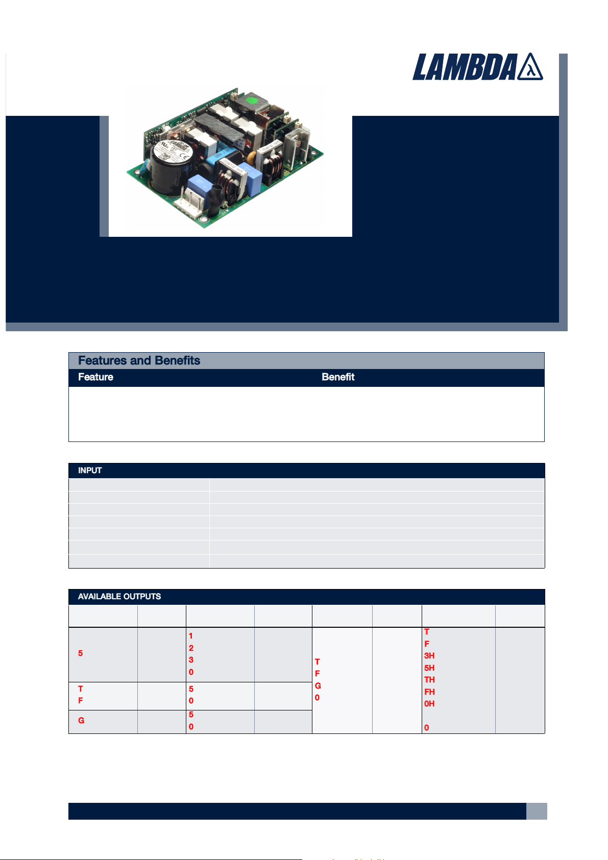
NV-POWER SERIES (NV-175)
NV-175 Datasheet - Document Number 69530 - Revision 10.1 April 06
1
Features and Benefits
Feature Benefit
u High Efficiency u Minimises heat in system
u Low Profile u Fits 1U applications
u High Power Density u Less Space
• High Efficiency
• High Power Density (9.3W/in3)
• Up to 5 outputs
• No minimum load
• Fits 1U applications
• Medical Approval
• 3 Year Warranty
Key Market Segments & Applications
Instrumentation Broadcast
Medical ATE
Automation Industrial Computing
Security Lifesciences/Laboratory
Network Servers and Routers
NV-Power
175/180/200 Watts, flexible power solution
AVAILABLE OUTPUTS
Channel 1
Adjustment
Range
Channel 2
1
Adjustment
Range
Channel 3
Adjustment
Range
Channel 4
3
Adjustment
Range
5
5V / 25A
2
5 - 5.5V
1
1.8V / 15A
2
2.7V / 15A
3
3.3V / 15A
0
Omit
0.9 - 3.3V
2.5 - 3.3V
2.5 - 3.3V
T
12V / 5A
F
15V / 5A
G
24V / 2.5A
0
Omit
12 - 15V
12 - 15V
18 - 24V
T
-12V / 1A
F
-15V / 1A
3H
-3.3V / 2A
5H
-5V / 2A
TH
-12.1V / 2A
FH
-15V / 2A
0H
Fan supply
only
0
Omit
Fixed
Fixed
Fixed
Fixed
Fixed
Fixed
T
12V / 15A
F
15V / 12A
12 - 15V
4
12 - 15V
5
5
5V / 10A
0
Omit
3.3 - 5.5V
G
24V / 7.5A
24 - 28V
6
5
5V / 8A
0
Omit
3.3 - 5.5V
5. 14.5 - 15V if 24V channel 3 fitted.
6. 24 - 24.5V if 5V channel 2 fitted
24 - 26V if 24V channel 3 fitted.
2. Maximum combined output current from Ch1 & Ch2 = 25A
Models with 5V channel 1 are limited to 175W output power
3. Follow letters in red by ‘P’ for positive output channel 4.
4. 12 - 12.5V if 24V channel 3 fitted.
Notes:
1. 1.8V, 2.7V, 3.3V channel 2 only available with 5V Channel 1
5V/10A channel 2 only available with 12V or 15V Channel 1
5V/8A channel 2 only available with 24V Channel 1.
Other output options are available, please contact factory with your requirements.
INPUT
Input Voltage 90 - 264Vac
Input Frequency 47 - 63Hz (440Hz with reduced PFC - consult factory)
Input Harmonics EN61000-3-2 compliant
Inrush Current <40A at 25°C and 264Vac, (cold start)
Input Fuse Fast acting (not user accessible)
Power Factor 0.97 typical
Earth Leakage Current 300µA max at 264Vac & 63Hz (normal condition, 500µA Single Fault Condition)
Page 2
NV-POWER SERIES (NV-175)
NV-175 Datasheet - Document Number 69530 - Revision 10.1 April 06
2
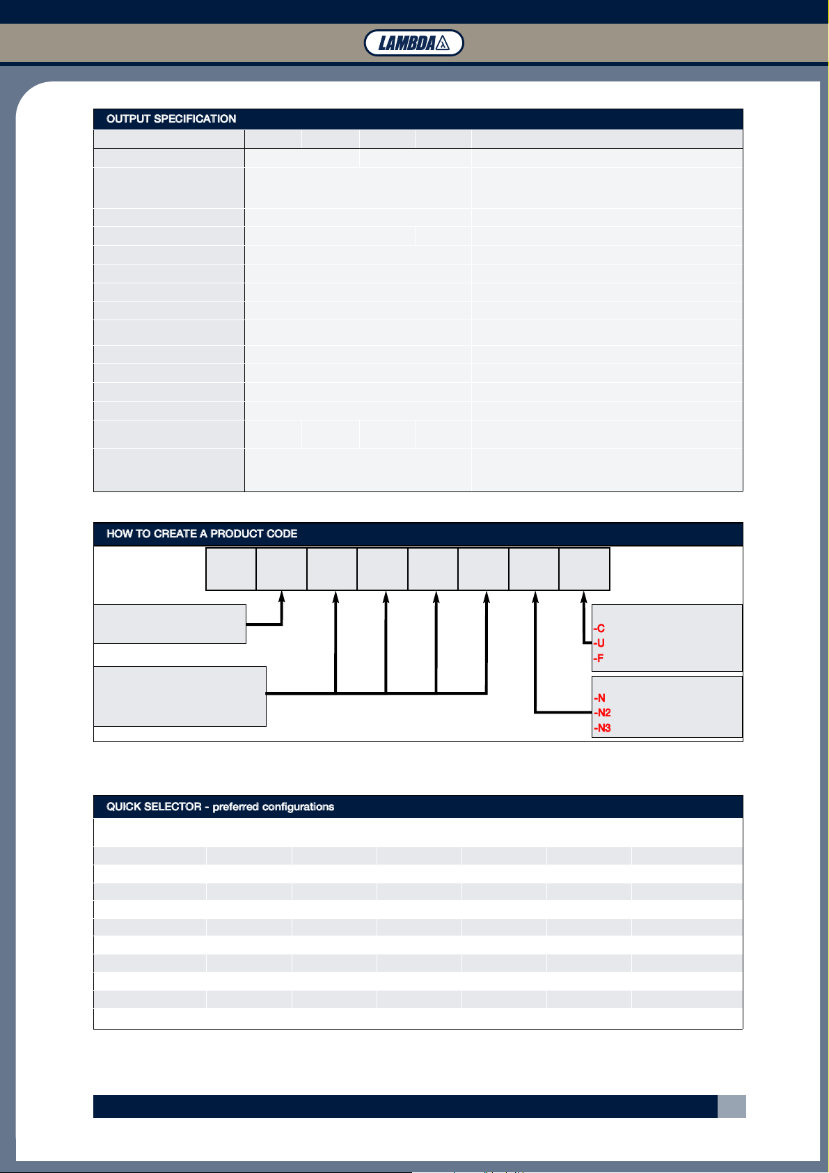
HOW TO CREATE A PRODUCT CODE
OUTPUT SPECIFICATION
Channel 1 Channel 2
Channel 3
Channel 4 Notes
Remote Sense
Yes No Max 0.5V total line drop
Total Regulation
1%
Including Line (for 90-264Vac input change), Load
(for 0-100% load change) and Cross (for 0-100%
load change on any other output) regulation
Ripple & Noise
maximum of 50mV or 1% pk-pk, using EIAJ test method & 20MHz bandwidth
Voltage Accuracy
±1% +4%/-3% ±4% for channel 4 with ‘T’ or ‘F’ type outputs
Turn on Time
1.5s max at 90 Vac & 100% rated output power
Efficiency
up to 90% configuration dependent
Hold up
16ms min at 90 Vac
Minimum Load
None on any output
Transient Response
<4%
of set voltage for 50% load change
(in 50µs within the range 25 - 100% load)
Recovery
<500µs for recovery to 1% of set voltage
Short circuit protection
Yes
OverTemperature protection
Yes
Over Voltage Protection
Yes See Application Notes for details
Ch1 Good Signal
Yes
Provides a Logic ‘Low’ signal after output is within
90% (±5%) of nominal.
Peak Output Power
200W
Units with 12V, 15V or 24V (T, F or G) channel 1.
Average output power must not exceed 180W over
any 5 minute period.
NV1- #o/p Ch1 Ch2 Ch3 Ch4
Global
Option
Case
Option
Number of outputs
(excluding standby supply)
Ch1 - Ch4 Letter/number from
above table to represent output voltage.
Confirm availability of created product code with the factory
(Blank = no case)
-C
= U Chassis + Cover
-U
= U Chassis
-F
= End fan + case
1
(Blank = no option)
-N
= 5V/2A
-N2
= 13.5/1A
-N3
= 5V/2A ATX compatible
1. see page 3 for details of global option
Above Units available on rapid delivery.
See over for additional variants available ‘Build to Order’
QUICK SELECTOR - preferred configurations
Model CH1 CH2 CH3 CH4 CH5
Global Option
1
NV1-1T000 12V / 15A - - - - No
NV1-1G000 24V / 7.5A - - - - No
NV1-453TT 5V / 25A 3.3V / 15A 12V / 5A -12V / 1A - No
NV1-453TT-N3 5V / 25A 3.3V / 15A 12V / 5A -12V / 1A 5V / 2A ATX (-N3)
NV1-453FF 5V / 25A 3.3V / 15A 15V / 5A -15V / 1A - No
NV1-453FF-N3 5V / 25A 3.3V / 15A 15V / 5A -15V / 1A 5V / 2A ATX (-N3)
NV1-4G5TT 24V / 7.5A 5V / 8A 12V / 5A -12V / 1A - No
NV1-4G5TT-N3 24V / 7.5A 5V / 8A 12V / 5A -12V / 1A 5V / 2A ATX (-N3)
NV1-4G5FF 24V / 7.5A 5V / 8A 15V / 5A -15V / 1A - No
NV1-4G5FF-N3 24V / 7.5A 5V / 8A 15V / 5A -15V / 1A 5V / 2A ATX (-N3)
1. Needs 0H, 3H, 5H, TH or FH type channel 4
Page 3

NV-POWER SERIES (NV-175)
NV-175 Datasheet - Document Number 69530 - Revision 10.1 April 06
3
ISOLATION
Input to Output Reinforced 4.3kV (dc)
Input to Earth Basic 2.3 kV (dc)
Output to Earth 200 V (dc)
GLOBAL INTERFACE SIGNALS -N3 Option Models (see application note for details)
ATX Remote on/off TTL logic level high or open circuit will inhibit all outputs (except Standby)
ATX Power Good Logic high indicates ac supply is good and output 1 is within regulation.
Standby Supply 5V / 2A (2.5A peak). Common 0V with power supply. Not affected by ATX remote on/off
ENVIRONMENT
Temperature
0 to 50°C operational, -40°C to 85°C storage (max 12 months)
Full load with 2m/s air blown from input to output
Convection Rating See Application note for details
Derating 50 to 70°C derate each output by 2.5% per °C
Low Temperature Start -20°C
Humidity 5 - 95% RH non condensing
Shock
±3 x 30gshocks in each plane, total 18 shocks
30gshock = 11ms (+/-0.5msec), half sine
Conforms to EN60068-2-27, EN60068-2-47, IEC68-2-27, IEC68-2-47, JIS C0041-1987.
Conforms to MIL-STD-810E/F, Method 514.4, Pro I, Cat 1,9
Vibration
Single axis 10 - 500 Hz at 2g(sweep and endurance at resonance) in all 3 planes
Conforms to EN60068-2-6, IEC68-2-6
Conforms to MIL-STD-810E, Method 516.5, Pro I, IV, VI
Altitude 3,000 metres operational
Pollution Degree 2, Material group 3
IMMUNITY EN61000-6-2:2001 Criteria
Electrostatic Discharge
EN61000-4-2 Level 3
Air discharge 8kV
Contact discharge 4kV
A
Electromagnetic Field
EN61000-4-3 Level 3 (12V/m) A
Fast / Burst Transient
EN61000-4-4 Level 4 (tested to 4.4kV) A
Surge Immunity
EN61000-4-5 Level 3
Common mode to 2.2kV
Differential mode to 1.1kV
A
Conducted RF Immunity
EN61000-4-6 Level 3 (12V) A
Power Frequency Magnetic Field
EN61000-4-8 Level 4 (30A/m) A
Voltage Dips, Variations, Interruptions
EN61000-4-11 Pass
EMISSIONS EN61000-6-3:2001
Radiated Electric Field EN55022
(as per CISPR.22) Class A,
Class B see application note for details
Conducted Emissions EN55022 Class B (as per CISPR.22)
Conducted Harmonics EN61000-3-2 Compliant
Flicker EN61000-3-3 Compliant
GLOBAL INTERFACE SIGNALS -N and -N2 Option Models (see application note for details)
Remote on/off TTL logic level high will inhibit all outputs (except Standby)
Power Good Open collector output (referenced to PSU 0V)
Standby Supply
Isolated supply, not affected by remote on/off
-N option = 5V / 2A (2.5A peak). -N2 Option = 13.5V / 1A
Page 4

NV-POWER SERIES (NV-175)
NV-175 Datasheet - Document Number 69530 - Revision 10.1 April 06
4
Top View
NV175-C Models
Top View
NV175-N-C & NV175-N3-C
Models
Side View
NV175-C & NV175-U
Models
Bottom View
NV175-N-C, NV175-N3-C
NV175-N-U & NV175-N3-U
Models
Notes
1. All customer fixings M3
2. Maximum Penetration 4.5mm
3. Maximum torque 0.9Nm
4. All tolerances +/-0.5mm
Side View
NV175-N-C, NV175-N3-C
NV175-N-U & NV175-N3-U
Models
Bottom View
NV175-C & NV175-U
Models
OUTLINE & CONNECTION DRAWINGS
SAFETY APPROVALS
Date Amendments
Date
Amendments
EN 60950-1
2001 EN 61010-1 2001
UL 60950-1
2003 IEC 61010-1* 2001
CSA 22.2 No 60950-1
2003 IEC 60601-1 1988
IEC 60950-1*
2001 EN 60601-1 1990 A1:1991, A2:1995
CE Mark
LV Directive 72/23/EEC(EN60950-1:2001) UL 60601-1 2001 A1:1993, A2:1995, A13:1996
* CB certificate and Report available on request Check with factory for status of approvals
All drawings relate to both 175W and 180W versions
Page 5

NV-POWER SERIES (NV-175)
NV-175 Datasheet - Document Number 69530 - Revision 10.1 April 06
5
Side View
NV175 All versions
Top View
NV175 Models
End View
Top View
NV175-N, NV175-N2 & NV-175-N3
Models
OUTLINE & CONNECTION DRAWINGS
CONTINUED
All drawings relate to both 175W and 180W versions
Page 6

NV-POWER SERIES (NV-175)
NV-175 Datasheet - Document Number 69530 - Revision 10.1 April 06
6
LAMBDA EMEA
FRANCE
LAMBDA SAS Telephone: +33 (0) 1 60 12 71 65
ZAC des Delaches, BP1077 - Gometz le Chatel Facsimile: +33 (0) 1 60 12 71 66
91940 Les Ulis Web: www.lambda-f.com
GERMANY
LAMBDA GmbH Telephone: +49 (0) 78 41 666 0
Karl-Bold-Straße 40 Facsimile: +49 (0) 78 41 5000
D-77855 Achern Web: www.lambda-germany.com
ISRAEL
NEMIC LAMBDA LTD Telephone: +972 (0) 3 902 4333
Kibbutz Givat Facsimile: +972 (0) 3 902 4777
Hashlosha 48800 Web: www.nemic.co.il
ITALY
LAMBDA s.r.l. Telephone: +39 (0) 02 61 29 38 63
Via dei Lavoratori 128/130, Facsimile: +39 (0) 02 61 29 09 00
20092, Cinisello Balsamo (Mi) Web: www.lambda-italy.com
SWEDEN
LAMBDA SCANDINAVIA Telephone: +46 (0) 8 598 94 090
PO Box 546, Rallervägen 41 Facsimile: +46 (0) 8 540 66 096
SE-184 25. Åkersberga Web: www.lambda-scandinavia.com
UK
LAMBDA UK Telephone: +44 (0) 1271 856666
Kingsley Avenue Facsimile: +44 (0) 1271 864894
Ilfracombe Devon EX34 8ES Web: www.lambda-gb.com
AUSTRIA
LAMBDA ELECTRONICS GmbH Telephone: +43 (0) 2256 655 84
Aredstraße 22 Facsimile: +43 (0) 2256 645 12
A-2544 Leobersdorf Web: www.lambda-austria.com
LAMBDA NORTH AMERICA
LAMBDA ASIA
LOCAL DISTRIBUTION
visit www.lambdapower.com for a list of Lambda offices and distributors
visit www.densei-lambda.com for a list of Lambda offices and distributors
 Loading...