

Page 1

OPERATION MANUAL
Rev. 1.01 ( 20071128)
MPC
MPC----365
MPCMPC
Narrow
Narrow----Format
NarrowNarrow
Micromanipulator
Micromanipulator
MicromanipulatorMicromanipulator
System
System
SystemSystem
365
365365
Format
FormatFormat
Page 2

Page 3

MP
MP----365
MPMP
365
365365
Narrow-Format
Micromanipulator System
Operation Manual
(Rev. 1.01 (20071128))
Sutter Instrument Company
One Digital Drive
Novato, CA 94949
voice: 415-883-0128 web: www.sutter.com
fax: 415-883-0572 email: info@sutter.com
Page 4

II
Copyright © 2007 Sutter Instrument Company. All Rights Reserved.
MPC365 NARROW-FORMAT MICROMANIPULATOR SYSTEM OPERATION MANUAL – REV. 1.01 (20071128)
Page 5

III
TABLE OF CONTENTS
TABLE OF CONTENTS
TABLE OF CONTENTSTABLE OF CONTENTS
1. INTRODUCTION .................................................................................................................................................................... 1
1.1 S
TRUCTURE OF THE
1.2 C
OMPONENTS OF THE
2. MPC-200 MULTI-MANIPULATOR CONTROLLER AND ROE-200 INPUT DEVICE OPERATIONS ............ 3
2.1 E
LECTRICAL CONNECTIONS AND INITIAL OPERATING INSTRUCTIONS
2.2 I
NITIAL OPERATING INSTRUCTIONS
2.3 M
AIN CONTROLS ON THE
2.3.1 White Buttons: ...............................................................................................................................................................4
2.3.2 Black Selector Switches: ...............................................................................................................................................6
2.3.3 Other Controls on the ROE-200...................................................................................................................................7
2.4 C
ONTROLS ON THE
3. MP-265/M MANIPULATOR MECHANICAL MOUNTING INSTRUCTIONS......................................................13
3.1 M
OUNTING
3.2 S
ETTING HEADSTAGE/PIPETTE ANGLE AND PIPETTE EXCHANGE
3.3 H
EADSTAGE MOUNTING
3.4 O
THER ACCESSORIES
3.5 M
INIMIZING ELECTRICAL NOISE
3.6 I
NSTRUCTIONS USED IN SPECIAL INSTALLATIONS ONLY
3.6.1 Installing and Using the Right-Angle Adapter (285300)...........................................................................................17
3.6.2 Instructions for Changing Handedness......................................................................................................................18
APPENDIX A. FUSE REPLACEMENT ...............................................................................................................................19
APPENDIX B. TECHNICAL SPECIFICATIONS..............................................................................................................21
MP-265/M
MPC-365 D
MPC-365...........................................................................................................................................1
MPC-200...............................................................................................................................................9
TO THE
..........................................................................................................................................................17
OCUMENTATION PACKAGE
......................................................................................................................................3
ROE-200.....................................................................................................................................4
MT-72 LS........................................................................................................................13
.....................................................................................................................................................16
........................................................................................................................................17
..............................................................................................1
...............................................................................3
.....................................................................................16
..................................................................................................17
MP-265 M
MPC-200 C
ROE-200 I
INDEX ..........................................................................................................................................................................................23
ICROMANIPULATOR MECHANICAL
ONTROLLER
NPUT DEVICE
...........................................................................................................................................................21
...........................................................................................................................................................21
.........................................................................................................................21
MPC365 NARROW-FORMAT MICROMANIPULATOR SYSTEM OPERATION MANUAL – REV. 1.01 (20071128)
Page 6

Page 7

1
1.
1. IN TRO DUC TI ON
INT RODU CTI ON
1.1.
INT RODU CTI ONINT RODU CTI ON
1.1
1.1 Structure of the MPC
Structure of the MPC----365 Documentation Package
1.11.1
Structure of the MPCStructure of the MPC
The MPC-365 is a manipulator system comprised of the MPC-200 controller, the ROE-200
input device and the MP-265/M narrow format stepper motor manipulator. The manual
consists of two parts, "Operations" that describes the functions of the MPC-200 controller
and ROE input device and "Setup" that describes how to install the MP-265/M mechanical
micromanipulator.
1.2
1.2 Components of the MPC
Components of the MPC----365
1.21.2
Components of the MPCComponents of the MPC
Carefully remove all components from the shipping container. In addition to this manual, the
following should be included:
• MPC-200 controller
• ROE-200 Rotary Optical Encoder input device
• MP-265/M narrow format manipulator mechanical
• Compact DB 26 to DB-25 cable (connects MP-265/M to the controller).
• RJ-45 cable (8 conductor) connects the ROE to the controller
• USB cable for computer control of the MPC-365 system
• Power cable (for the MPC-200 controller) appropriate for your location
• 2.5mm hex wrench for removing the shipping screws
• 1.5mm hex wrench for adjusting pipette angle
• MT-72 LS long slide on tower gantry for mounting the MP-265/M. Included is an MT-
7004 levered clamp for locking the MP-265/M’s mounting mechanism at any point along
the horizontal slide that is mounted atop the vertical tower gantry.
365 Documentation Package
365 Documentation Package 365 Documentation Package
365
365365
IMPORTANT
IMPORTANT
IMPORTANT IMPORTANT
Once you have unpacked your MPC
Once you have unpacked your MPC----365, remove the two shipping screws, indicated by
Once you have unpacked your MPCOnce you have unpacked your MPC
red warning tags, from the MP
red warning tags, from the MP----265/M. You must remove these screws before operating the
red warning tags, from the MPred warning tags, from the MP
manipulator. Save the screws, warning tags, and hex wrench in the event you need to
manipulator. Save the screws, warning tags, and hex wrench in the event you need to
manipulator. Save the screws, warning tags, and hex wrench in the event you need to manipulator. Save the screws, warning tags, and hex wrench in the event you need to
transport your manipulator in the future. Once these screws have been removed, ha
transport your manipulator in the future. Once these screws have been removed, handle the
transport your manipulator in the future. Once these screws have been removed, hatransport your manipulator in the future. Once these screws have been removed, ha
micromanipulator with care. The mechanism can be damaged if the axes are moved with the
micromanipulator with care. The mechanism can be damaged if the axes are moved with the
micromanipulator with care. The mechanism can be damaged if the axes are moved with the micromanipulator with care. The mechanism can be damaged if the axes are moved with the
screws in place.
screws in place.
screws in place.screws in place.
MPC365 NARROW-FORMAT MICROMANIPULATOR SYSTEM OPERATION MANUAL – REV. 1.01 (20071128)
365, remove the two shipping screws, indicated by the
365, remove the two shipping screws, indicated by 365, remove the two shipping screws, indicated by
265/M. You must remove these screws before operating the
265/M. You must remove these screws before operating the 265/M. You must remove these screws before operating the
the
the the
ndle the
ndle the ndle the
Page 8

Page 9
3
MANIPULATORS
CONTROLLER
FUSE HOLDER
2.
2. M PC
MPC ----2 00 M ULTI
2.2.
MPCMPC
INP UT D EVI CE O PERA TI
INP UT D EVI CE O PERA TIO NS
INP UT D EVI CE O PERA TIINP UT D EVI CE O PERA TI
2.1
2.1 Electrical Connections and Initial Operating Instructions
Electrical Connections and Initial Operating Instructions
2.12.1
Electrical Connections and Initial Operating InstructionsElectrical Connections and Initial Operating Instructions
Initially, you may want to simply connect your two manipulators, the controller, and the
ROE together and try some gross movements in order to get a feel for the controls and how
to make simple movements. It is perfectly acceptable to set the manipulators in the middle
of a bench top, make all electrical connections and then observe each unit’s movement by
eye. Even if you wish to directly install the manipulators in your rig, it is useful to follow the
initial setup procedure to learn how to move the units to allow easy access to the mounting
screws.
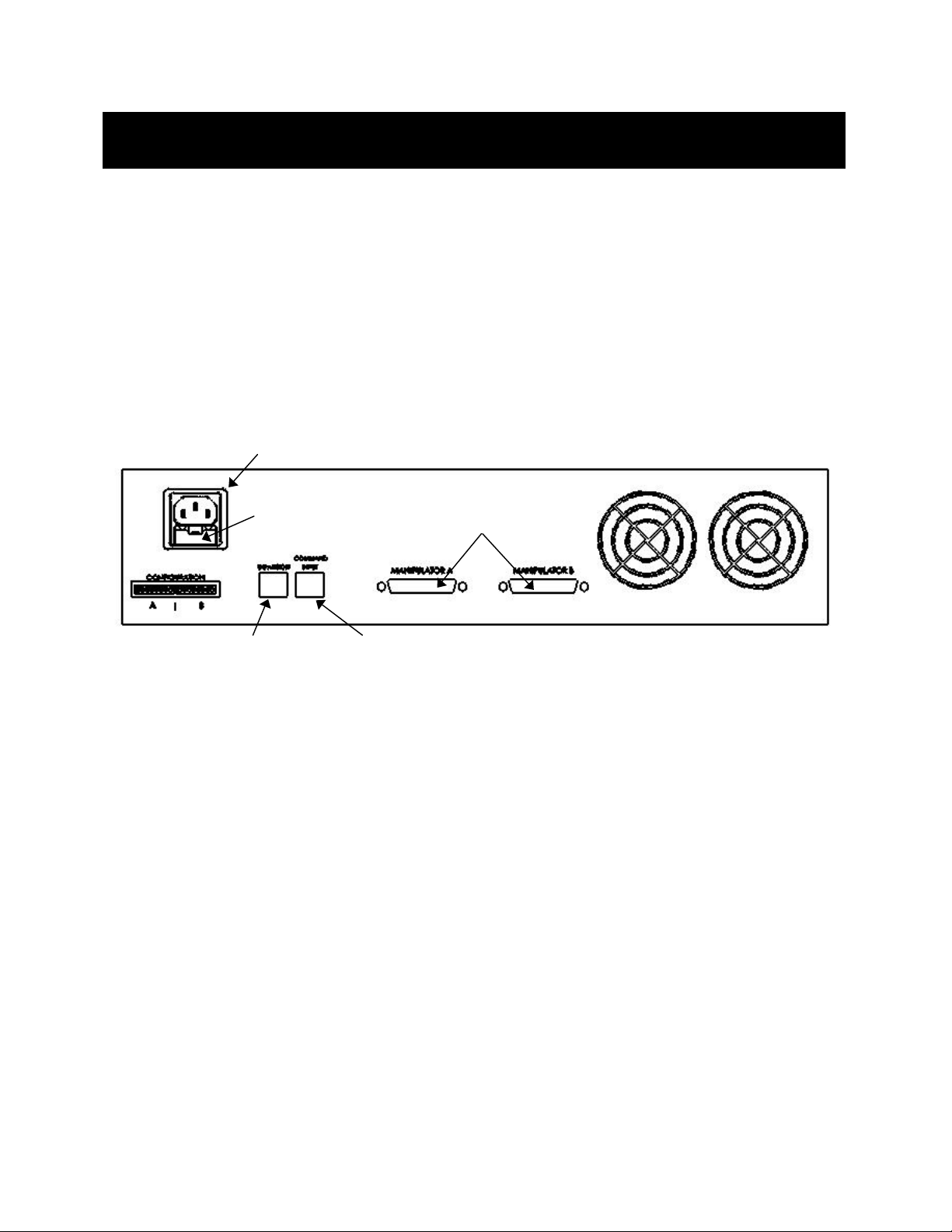
1. Connect the power cord to the power entry module on the back of the MPC-200
controller.
200 MUL TI----M ANIP U
200 MUL TI200 MUL TI
POWER CORD
MAN IPU LAT OR C ONTR OLLE R A ND
MAN IPUMAN IPU
LAT OR C ONT RO LLE R AN D R OE
LAT OR C ONT RO LLE R AN DLAT OR C ONT RO LLE R AN D
ONS
ONSONS
RO E----2 00
RO E RO E
200
200 200
CONNECT
DAISY CHAIN SECOND
2. With the power OFF (front panel switch in the “0” position), connect the ROE-200 input
box to the MPC-200 controller using the RJ-45 8-conductor cable. **** Use the
CONTROLLER output on the back of the ROE and the COMMAND INPUT on the back
of the controller.
3. With the power OFF, run a DB-25-to-DB26 HD cable from each of the two MP-265/M
mechanicals to the DB-25 connectors marked “MANIPULATOR A” and
“MANIPULATOR B” on the back of the controller. ****
*NOTE: Never connect or dis
*NOTE: Never connect or disconnect the ROE or the MP
*NOTE: Never connect or dis*NOTE: Never connect or dis
controller while the power is on!
controller while the power is on!
controller while the power is on!controller while the power is on!
2.2
2.2 Initial Operating Instructions
Initial Operating Instructions
2.22.2
Initial Operating InstructionsInitial Operating Instructions
CONNECT ROE-200
Figure 2-1. Rear of MPC-200 controller cabinet..
connect the ROE or the MP----265/M to and from the MPC
connect the ROE or the MPconnect the ROE or the MP
265/M to and from the MPC----200
265/M to and from the MPC265/M to and from the MPC
200
200 200
After all electrical connections have been made, you can power up the MPC-365 using the 0/I
switch on the front of the controller. As it initializes, you will see a start up screen on the
ROE-200 that briefly displays the name of the device and the version of the installed
firmware. As the power switch is the only control you will need to access on the MPC-200,
the controller can ultimately be placed in an out of the way location (e.g., under your bench).
Once the start-up sequence has finished, you will see a display that gives the coordinates of
the connected manipulator. The LED marked 1 will light if you connected the MP-265/M to
MPC365 NARROW-FORMAT MICROMANIPULATOR SYSTEM OPERATION MANUAL – REV. 1.01 (20071128)
Page 10

4
the connector marked MANIPULATOR A. Confirm that you get a coordinate display and
have removed the shipping screws. If you do not get a coordinate display, go to the trouble
shooting section at the back of the manual. If you have not yet removed the six shipping
screws, turn the power back off and remove the six screws.
All functions necessary during normal operation are provided by four push buttons and two
rocker switches on the top of the ROE-200. Other setup functions are done via buttons and
DIP switches located on the back of the ROE-200 and DIP switches on the back of the MPC200 controller.
The three ROE knobs control the three axes of the manipulator (right knob X, left knob Y,
and top knob Z, see Page 5). Turn any one of the three knobs and notice that the
corresponding axis moves and the coordinate for that axis changes.
The MPC-200 controller and ROE-200 have a built in Centering function. This is activated
by pressing the white “CENTER” button on the back of the ROE. If the MP-265/M
manipulator is sitting in a wide-open area, and the shipping screws are removed, press the
CENTER button. The ROE-200 display will display the message “PLEASE WAIT MOVE IN
PROGRESS”. After the CENTER operation is complete, the manipulator axes will each be
at the center of travel and the display will read 12500 for X and Z, and 6250 for Y.
From this location, you can move 12500 microns in each direction on the X- and Z-axis, and
6250 on the Y-axis. The unit will stop automatically at each end of travel (00000 or 25000
microns for X and Z, and 00000 or 12500 for Y). These ends are determined by firmware.
Each axis also have magnetic end of travel switches that are not activated in normal
operation. If the magnetic switches are activated, you will see the message EOT (for End Of
Travel) on one of the displayed axes.
When the MPC-200 controller is first turned on, the speed of movement is at its fastest,
coarsest Mode. Movement mode can be finer and slower by changing the black “Mode”
toggle switch. As MODE increases from 0, smaller movements are commanded by the same
turn of the ROE knob. MODE 5 or 6 is probably what you will use for the final approach to a
cell. MODE 0 or “Accelerated Mode” is used for fast movements to move the pipette large
distances. In MODE 0, when the ROE knob is turned slowly, a relatively slow movement is
achieved that is useful for final moves to place a pipette near a cell. Conversely, when you
make prolonged, rapid turns of the ROE knob, the controller/ROE automatically accelerates
to maximum speed to allow for prolonged, long distance movements. This would be most
useful for manual pipette exchange.
The remaining functions of the ROE are explained in the next section.
2.3
2.3 Main Controls on the ROE
Main Controls on the ROE----200
2.32.3
Main Controls on the ROEMain Controls on the ROE
2.3.1
2.3.1 White Buttons:
White Buttons:
2.3.12.3.1
White Buttons:White Buttons:
DIAG/NORM:
DIAG/NORM: Pressing the DIAG/NORM button will cause the green LED near the button to
DIAG/NORM: DIAG/NORM:
200
200200
light, indicating the MPC-200/ROE-200 is in Diagonal mode. In this mode, rotation of the Zaxis knob produces diagonal movement. A second press will put the manipulator back into
Normal mode. When in diagonal mode, the X and Y knobs remain active, allowing you to
readjust the X and Y positioning of the pipette as you approach a cell in diagonal mode. Angle
of diagonal mode movement is set via DIP switches on the back of the MPC-200 controller.
(See Controller DIP switch setting instructions on Pages 9 through10). When using MODE 9
MPC365 NARROW-FORMAT MICROMANIPULATOR SYSTEM OPERATION MANUAL – REV. 1.01 (20071128)
Page 11

5
(MODE toggle set to 9), Diagonal mode produces short, quick, impulse-like movement that
may be useful in sharp pipette impalements.
When you switch to Diagonal mode, the ROE-200 display is changed from absolute to relative
coordinates and the current location is set to 0,0,0. This allows users to invoke relative
measurements using the display as a measuring device. A fourth coordinate that gives
movement along the diagonal is also added for users who wish to measure the movement of
along the axis coaxial with a pipette. When you return to Normal mode, the absolute
coordinate system is recovered. The relative coordinate feature can be disabled via DIP
switch 2 on back of the ROE-200.
Figure 2-2. Top view of ROE-200..
HOME:
HOME: When pressed, the manipulator will make a move along a stereotypic path to the
HOME: HOME:
location 0,0,0 or "home”. Home is the location where you would most likely exchange your
pipette and is maximal up on the Z-axis, maximal right on the Y-axis (maximal left on a lefthanded manipulator) and maximal front on the X-axis. The stereotypic path of the movement
is first along the currently set diagonal until either the X-or Z-axis reaches its origin (0).
Which one of these occurs first is a function of the diagonal angle and the location at the time
HOME is pressed. Once the first limit is reached, the unit will move the two remaining axes
simultaneously to their origins (0). The only allowed change in this stereotyped move is that
the Y-axis move can be eliminated. This is done via DIP switch 8 on the back of the MPC-200
controller (see Controller DIP switch setting instructions on Page 11).
WORK POS.
WORK POS.: This button has three functions:
WORK POS.WORK POS.
1. With the STOP/SET button is held down, a momentary press of WORK POS. makes the
current location the "Work Position". A beeper will sound to indicate that the operation is
complete and the location has been saved. Typically, this is a location where the pipette
tip is under the microscope objective and near the cells or tissue of interest.
MPC365 NARROW-FORMAT MICROMANIPULATOR SYSTEM OPERATION MANUAL – REV. 1.01 (20071128)
Page 12

6
2. Once you have defined a Work Position, a momentary press of WORK POS. will cause the
manipulator to move to the defined Work Position, providing the manipulator’s last move
was to Home. The move will occur along the predefined path that the manipulator moved
to get to Home (described above) but in the opposite direction. This is the reason why
Work Position moves must
must follow Home moves; the move to Home defines the return
mustmust
trip. In either case, the movement along the diagonal as you come in and out of the
preparation/dish/bath should assure that the pipette tip would not hit anything on the
way in or out.
3. When WORK POS. is held down for longer than 2 seconds, the current manipulator is
locked so that none of the buttons or the ROE knobs will cause it to move. The lock is
released by holding WORK POS. down again. A beep will indicate that the lock is enabled
or disabled and the display will indicate the locked state.
Note that like HOME, the Y axis movement can be disabled when WORK POS is pressed, as
set via DIP switch 8 on the back of the MPC-200 controller (see Controller DIP switch
setting instructions on Page 11).
STOP/SET:
STOP/SET: This button has two functions:
STOP/SET: STOP/SET:
1. When held down, STOP/SET" performs a "Set" function in combination with the "WORK
POS." key. Think of it as a shift key when held down.
2. A momentary press of STOP/SET during a robotic move (see HOME, WORK POS. and
CENTER) will immediately "Stop" the movement. Think of this as your panic button
when you see your pipette headed somewhere that you don't want it to go!
when you see your pipette headed somewhere that you don't want it to go!
when you see your pipette headed somewhere that you don't want it to go!when you see your pipette headed somewhere that you don't want it to go!
Think of this as your panic button
Think of this as your panic button Think of this as your panic button
2.3.2
2.3.2 Black Selector Switches:
Black Selector Switches:
2.3.22.3.2
Black Selector Switches: Black Selector Switches:
MODE:
MODE: The MODE Selector controls the speed and the relative fineness of movement of the
MODE: MODE:
manipulator produced by rotating the ROE knobs. As MODE increases from 0 to 9,
movement gets finer and slower. As explained in "INITIAL OPERATING INSTRUCTIONS",
MODE 0 is Accelerated Mode. In MODE 0, slow turns of the ROE knob produce medium
course moves for moving a pipette under a microscope near a cell. Prolonged, fast turns of
the ROE knobs cause the controller to accelerate to top speed for long, imprecise movements
for rapid manual positioning of the pipette. The remaining MODES (1-9) produce moves of
increasing sensitivity and decreasing speed. In practice, most users will find that MODE 5 or
6 will provide the necessary dexterity of movement for the final approach to a cell. The
current MODE setting is displayed in the upper right of the ROE-200 display.
MANIPULATOR:
MANIPULATOR: The MANIPULATOR Selector toggles the active manipulator. In the
MANIPULATOR:MANIPULATOR:
MPC-365, there is only one active manipulator; therefore, the MANIPULATOR Selector has
no function. You can toggle the switch, but no change will occur. With only one manipulator
attached, the words "ROE-200" are displayed. If the manipulator is connected to the
"MANIPULATOR A" output on the back of the MPC-200 controller LED 1 will be lit. If
connected to "MANIPULATOR B", LED 2 will be lit. If you connect an additional MP-265/M
manipulator in the future, the controller will automatically detect the second manipulator,
the MANIPULATOR toggle will become active and the display will indicate which
manipulator is active with the words "Drive A" or "Drive B"
MPC365 NARROW-FORMAT MICROMANIPULATOR SYSTEM OPERATION MANUAL – REV. 1.01 (20071128)
Page 13
7
Figure 2-3. Side view of ROE-200..
2.3.3
2.3.3 Other Controls on the RO
Other Controls on the ROEEEE----200
2.3.32.3.3
Other Controls on the ROOther Controls on the RO
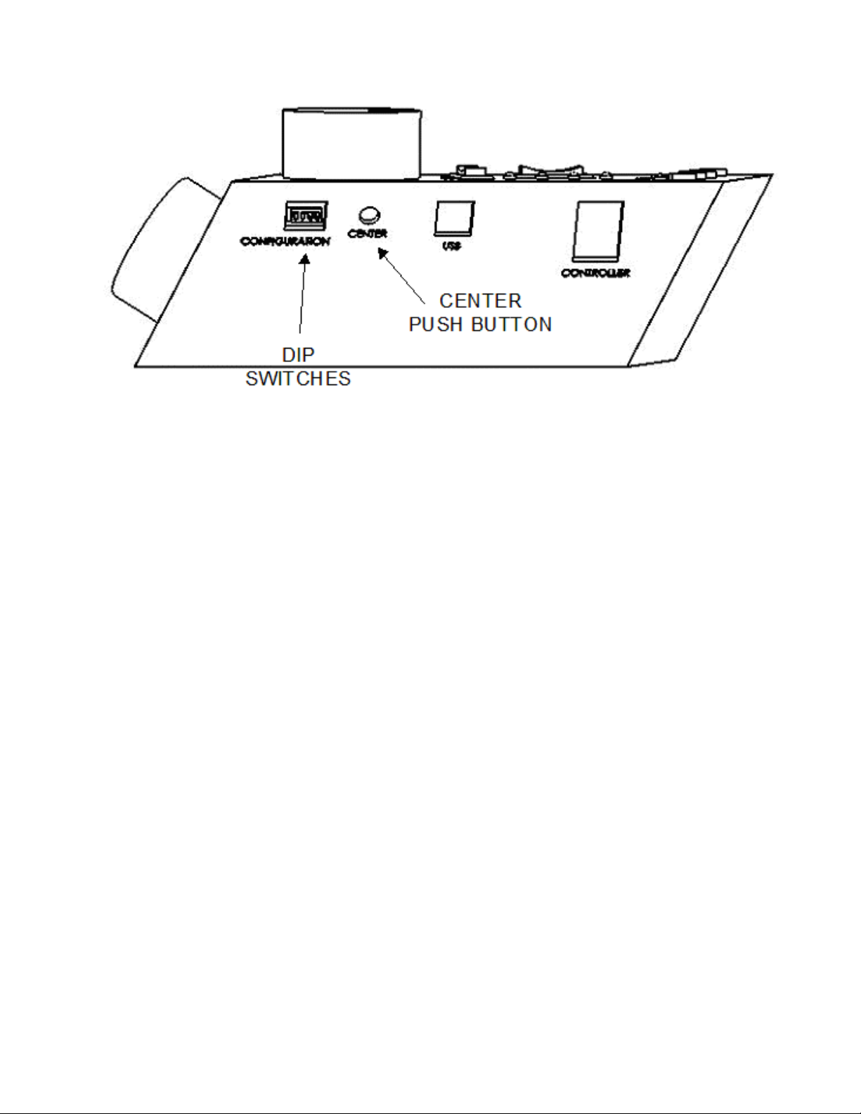
CENTER (round push button on the back of ROE
CENTER (round push button on the back of ROE----200)
CENTER (round push button on the back of ROECENTER (round push button on the back of ROE
200
200 200
200): CENTER is an initialization
200)200)
function that is used when the unit is first set up and occasionally during normal operation.
CENTER should only be done in the absence of a pipette as the manipulator makes large
CENTER should only be done in the absence of a pipette as the manipulator makes large
CENTER should only be done in the absence of a pipette as the manipulator makes large CENTER should only be done in the absence of a pipette as the manipulator makes large
robotic movements to its extreme ranges of motion.
robotic movements to its extreme ranges of motion. To CENTER, press and release the white
robotic movements to its extreme ranges of motion. robotic movements to its extreme ranges of motion.
button on the back of the ROE-200. This will cause a prolonged movement in each axis to the
end of travel (EOT) sensors beyond the origin (0,0,0). Once the sensors are found, a short
move in the opposite direction is made and this location is defined as (0,0,0). Finally, the unit
moves to the location (12500 (X), 6250 (Y), 12500 (Z)), the center of travel of each axis. If the
unit is turned off, or STOP/SET is pressed during the running of CENTER, the unit will not
be correctly initialized. In this case, it is necessary to cycle the power off and on and run
CENTER again to its completion.
DIP Switches (on back of ROE
DIP Switches (on back of ROE----200):
DIP Switches (on back of ROEDIP Switches (on back of ROE
200): There are four DIP switches on the back of the ROE-
200): 200):
200 which govern global and/or ROE settings.
Switch 1:
Switch 1: When ON, all modes on the MODE selector, except Mode 0 and 5, are disabled.
Switch 1:Switch 1:
Some users may find that they only need Accelerated Mode and a single fine mode. This will
allow them to more easily switch between the two. Factory default is OFF, enabling all
modes.
Switch 2:
Switch 2: When OFF, relative coordinates during Diagonal Mode are disabled. The factory
Switch 2: Switch 2:
default is ON (display of relative coordinates enabled during Diagonal Mode).
Switch 3:
Switch 3: When OFF, the MANIPULATOR Selector functions in a cyclical fashion. After
Switch 3: Switch 3:
reaching the highest-numerated manipulator, a further push of MANIPULATOR cycles the
user back to the lowest-numerated manipulator. When DIP switch 3 is set to ON, the selector
does not cycle back to the first manipulator. Factory default is OFF, allowing cycling back.
Switch 4:
Switch 4: Reserved for future use. NOTE: Must be kept ON for proper functioning!
Switch 4:Switch 4:
MPC365 NARROW-FORMAT MICROMANIPULATOR SYSTEM OPERATION MANUAL – REV. 1.01 (20071128)
NOTE: Must be kept ON for proper functioning!
NOTE: Must be kept ON for proper functioning!NOTE: Must be kept ON for proper functioning!
Page 14

8
NOTES
NOTES
NOTESNOTES
MPC365 NARROW-FORMAT MICROMANIPULATOR SYSTEM OPERATION MANUAL – REV. 1.01 (20071128)
Page 15

9
2.4
2.4 Controls on the MPC
Controls on the MPC----200
2.42.4
Controls on the MPCControls on the MPC
Power Switch:
Power Switch: The power switch for the MPC-200 is located on the front panel of the
Power Switch: Power Switch:
200
200 200
controller. At power up, the microprocessor in the ROE-200 scans the attached equipment
and configures the system accordingly. Among the checks/configurations that are made:
1. Determines the number and type of manipulators that are attached. The MPC-200/ROE-
200 system is able determine how many and what type of manipulators (MP-285/M, MP225/M, or MP-265/M) are connected and to what outputs they are connected. It then sets
the current for each output to the correct value for the mechanicals found. If no
manipulators are found, the controller will return the message "NO MANIPULATOR
DETECTED, PLEASE TURN OFF CONTROLLER AND ATTACH MANIPULATOR"
2. The ROE-200 is capable of connecting to more than one MPC-200 controller. On power
up the ROE makes a determination of how many controllers are attached and configures
properly. If the power is off on the second controller, the ROE-200 displays a message
"PLEASE TURN ON ALL CONTROLLERS, THEN PRESS SET TO START".
DIP Switches:
DIP Switches: Two banks of eight DIP switches are located on the back of the MPC-200
DIP Switches:DIP Switches:
controller. Each bank is assigned to (and configures) one of the two manipulator outputs on
the back of the controller (MANIPULATOR A or B). Users familiar with the Sutter
Instrument MP-225 controller will find that they have the same function as the
configuration DIP switches on the MP-225 ROE. The switches are numbered 1 through 8. In
all cases, the 0 or OFF position is opposite the direction of the switch number and the 1 or
ON position is in the direction of the switch number and is also indicated by an arrow and
the word "ON" next to Switch 1. In order for any new switch settings to take effect, the
controller must be powered off and on.
The figure below shows the two banks of switches on the back of the MPC-200 controller.
Figure 2-4. Configuration switches on rear of MPC-200 controller cabinet.
Switches 1,2,3 and 4
Switches 1,2,3 and 4 set the angle of the Diagonal mode movement.
Switches 1,2,3 and 4Switches 1,2,3 and 4
The table on the next page gives the angles that can be used and the DIP switch settings of
switches 1, 2, 3 and 4. As indicated in the inset to the left of the table, the angles fall into two
different quadrants according to whether the angles are more or less steep than 45 degrees.
MPC365 NARROW-FORMAT MICROMANIPULATOR SYSTEM OPERATION MANUAL – REV. 1.01 (20071128)
Page 16

10
Table 2-1. Configuration switch settings for different angles of steepness.
Angle
DIP switch number
1 2 3 4
7 1 1 1 1
11 0 1 1 1
14 1 0 1 1
21 0 0 1 1
27 1 1 0 1
29 * 0 1 0 1
35 1 0 0 1
39 0 0 0 1
45 1 1 1 0
DIP switch number
Angle
1 2 3 4
39 0 1 1 0
35 1 0 1 0
29 0 0 1 0
27 1 1 0 0
21 0 1 0 0
14 1 0 0 0
11 0 0 0 0
*Factory default near 30
degrees
Switches 5, 6 and 7
Switches 5, 6 and 7 set the direction of the movement produced by a clockwise turn
Switches 5, 6 and 7Switches 5, 6 and 7
(advancing right hand screw) of the ROE knob for each axis.
With the switch set to 0, a clockwise turn of the knob produces a decrement in the display;
when the switch is set to 1, a clockwise turn of the knob produces an increment in the
display. An increment in the display coincides with movement downward in the Z axis,
movement toward the rear of your setup in the Y axis and movement producing pipette
advancement in the X axis.
MPC365 NARROW-FORMAT MICROMANIPULATOR SYSTEM OPERATION MANUAL – REV. 1.01 (20071128)
Page 17

11
The factory default is 1,1,1 for switches 5,6 and 7.
Switch number 5 6 7
Corresponding axis X Y Z
NOTE: Any channel that uses a left
NOTE: Any channel that uses a left----side MP
NOTE: Any channel that uses a leftNOTE: Any channel that uses a left
This is because a left
This is because a left----handed MP
This is because a leftThis is because a left
counterpart, and thus it is usually desirable to have the manipulator move back on its Y axis
counterpart, and thus it is usually desirable to have the manipulator move back on its Y axis
counterpart, and thus it is usually desirable to have the manipulator move back on its Y axis counterpart, and thus it is usually desirable to have the manipulator move back on its Y axis
with a counterclockwise turn of the ROE’s Y axis knob.
with a counterclockwise turn of the ROE’s Y axis knob.
with a counterclockwise turn of the ROE’s Y axis knob.with a counterclockwise turn of the ROE’s Y axis knob.
Switch 8
Switch 8 determines whether or not the Y-axis is included in HOME and WORK POS. robotic
Switch 8Switch 8
handed MP----265/M has
handed MPhanded MP
side MP----265/M, Switch 6 must be changed from 1 to 0.
side MPside MP
265/M has its Y
265/M has265/M has
265/M, Switch 6 must be changed from 1 to 0.
265/M, Switch 6 must be changed from 1 to 0. 265/M, Switch 6 must be changed from 1 to 0.
its Y----axis rotated 180° from its right
axis rotated 180° from its right----handed
its Y its Y
axis rotated 180° from its rightaxis rotated 180° from its right
handed
handed handed
moves. If switch 8 is set to 0, the Y axis is moved to a location where the pipette is towards
the user in a Home move and is moved back to whatever Y coordinate was recorded during
Set-Work Pos. in the Work Pos. move. If switch 8 is set to 1, the Y axis is not moved (Y
position ignored) during the HOME or WORK POS. moves. In the MPC
factory default for switch 8 is 1 (the Y axis is not moved (Y position ignored) during the
factory default for switch 8 is 1 (the Y axis is not moved (Y position ignored) during the
factory default for switch 8 is 1 (the Y axis is not moved (Y position ignored) during the factory default for switch 8 is 1 (the Y axis is not moved (Y position ignored) during the
HOME or WORK POS. moves).
HOME or WORK POS. moves).
HOME or WORK POS. moves).HOME or WORK POS. moves).
In the MPC----365 system, the
In the MPCIn the MPC
365 system, the
365 system, the 365 system, the
Figure 2-5. Configuration switches (rear of MPC-200 controller).
MPC365 NARROW-FORMAT MICROMANIPULATOR SYSTEM OPERATION MANUAL – REV. 1.01 (20071128)
Page 18

Page 19

13
3.
3. M P
MP ----2 65/M MAN IPU LATO R
3.3.
This chapter describes how to mount the MP-265/M to a stand (normally, the top plate of an
MT-72 LS), how to change pipettes and adjust pipette angle, and finally, the modular nature
of the mechanical.
3.1
3.1
3.13.1
The MP-265/M mounts to the top mounting plate of the MT-72 LS. Gently place the MP265/M onto the four mounting posts that are part of the mounting plate. Once placed evenly
on the mounting plate, tighten the miniature hex screws (two on each side) of the MP265/M’s X-axis slide using the supplied hex wrench.
265 /M M ANI PULA TOR MEC HANICAL MOU NTIN G
MPMP
265 /M M ANI PULA TOR265 /M M ANI PULA TOR
INS TRU CTIO NS
INS TRU CTIO NS
INS TRU CTIO NSINS TRU CTIO NS
Mounting MP
Mounting MP----265/M to the MT
Mounting MPMounting MP
265/M to the MT----72 LS
265/M to the MT265/M to the MT
ME CHAN ICAL MOU NTI NG
ME CHAN ICAL MOU NTI NG ME CHAN ICAL MOU NTI NG
72 LS
72 LS72 LS
Figure 3-1. Angled side view of MP-265/M mounted on an MT-72 LS.
MPC365 NARROW-FORMAT MICROMANIPULATOR SYSTEM OPERATION MANUAL – REV. 1.01 (20071128)
Page 20

14
Figure 3-2. Angled view of MP-265/M showing pipette holder and angle control and directions of all three axis.
MPC365 NARROW-FORMAT MICROMANIPULATOR SYSTEM OPERATION MANUAL – REV. 1.01 (20071128)
Page 21

15
Figure 3-3. MT-72 LS controls and adjustments.
Only the front pair of screws is visible in this figure. The adapter plate is normally shipped
in a small plastic bag also containing the necessary hardware.
in a small plastic bag also containing the necessary hardware.
in a small plastic bag also containing the necessary hardware.in a small plastic bag also containing the necessary hardware.
The adapter plate is normally shipped
The adapter plate is normally shipped The adapter plate is normally shipped
The figure above shows the plate removed from the X-axis. Before attaching the adapter
plate to the MP-265/M, you need to decide where to position the manipulator on your stand.
The stand can be any flat surface carrying ¼-20 or 10-32 holes on one-inch centers (such as a
Sutter MT-stands or MD series platforms). A good technique is to set the manipulator on
top of the adapter plate and slide it around on your stand until it is in a good location. Then
take the manipulator off and fix the adapter plate securely to the stand with the ¼-20 or 1032 hardware. Finally, align the holes on the bottom corners of the manipulator with the four
threaded holes on the corners of the adapter plate and attach the manipulator using the 4
supplied M3X0.5 metric cap screws.
MPC365 NARROW-FORMAT MICROMANIPULATOR SYSTEM OPERATION MANUAL – REV. 1.01 (20071128)
Page 22

16
3.2
3.2
Setting Headstage/Pipette Angle and Pip
Setting Headstage/Pipette Angle and Pipette Exchange
3.23.2
Setting Headstage/Pipette Angle and PipSetting Headstage/Pipette Angle and Pip
Mounted on the front of the Z-axis of the manipulator is the rotary dovetail. The rotary
dovetail is used to hold various electrophysiological headstages and/or micro tools at defined
angles.
The angle of the rotary dovetail is adjusted by loosening the hex set screw located on the
hinge side of the rotary dovetail (see figure below). You can set a particular angle using the
knife-edge on the dovetail and the scale on the faceplate. After choosing an angle, retighten
the screw to fix the angle.
Figure 3-4. Location of screw to loosen for changing pipette angle.
ette Exchange
ette Exchangeette Exchange
To change pipettes, squeeze the linear slide cantilever and pull the MP-265M back along the
slide mounted on the MT-75/LS gantry to a position that works best for removing and
replacing pipettes and/or rods.
3.3
3.3 Headstage Mounting
Headstage Mounting
3.33.3
Headstage MountingHeadstage Mounting
Axon headstages 203B or CV-7 and the Heka EPC-10 headstage have an integral dovetail
that slides directly into the rotary dovetail on the MP-265/M. The figure below shows an
example of this type of headstage mounted in a left-handed manipulator and in profile (on
the right), the location of the Phillips-head screw that secures the headstage dovetail in its
mate on the manipulator.
Figure 3-5. Headstage mounting.
Older Axon and Heka headstages mount using the 4-inch dovetail (X285204) and a plastic
plate. A typical headstage of this type is shown mounted in a right-handed MP-265/M (right
panel). The plastic plate used with the 4-inch dovetail is shown in the left panel of the figure
and the holes are indicated to mount common headstages. Additional holes could be easily
added to accommodate less common headstage footprints.
MPC365 NARROW-FORMAT MICROMANIPULATOR SYSTEM OPERATION MANUAL – REV. 1.01 (20071128)
Page 23

17
Connection to 4 inch dovetail:
EPC7,8 & 9: 1-1/16" x 2-7/32"
C
A
D
D D
C
C
B
(2 holes, A & B)
CV-4: 1-1/8" x 1-15/16"
(4 holes, B & C)
( 3 holes, D)
Figure 3-6. Using a dovetail for headstage mounting.
Rod mounted headstages and micro tools are accommodated by use of a rod clamp that fits
into the dovetail (not shown). All the headstage adapters and mounting hardware are
included with the manipulator and are shipped in a zip lock plastic bag.
3.4
3.4 Other Accessories
Other Accessories
3.43.4
Other Accessories Other Accessories
You may have received one or more accessories for mounting your MP-265/M and/or
modifying the headstage mount to the manipulator (i.e. rotating base, microscope stage
mount, gantry stand, dovetail extension). Setup of these accessories is normally covered in
documentation accompanying the accessory.
If you intend to use the right angle adapter (285300) with your MP-265/M in order to rotate
the manipulator 90 degrees, please see “Instructions used in Special Installations Only”
below.
3.5
3.5 Minimizing Electrical Noise
Minimizing Electrical Noise
3.53.5
Minimizing Electrical NoiseMinimizing Electrical Noise
We are aware of one potential noise source that users coupling their MP-365 with high-gain,
high-input impedance, electrophysiological recording amplifiers may experience. Under
certain circumstances, the manipulator and/or the drive cable coming from the controller
may act as an antenna picking up electric field noise from nearby electrical equipment and
bringing it into your setup. Grounding the manipulator will largely eliminate this noise
source. Try to attach to one of the silver Phillips-head screws on the side of one or more of
the axes. It should be noted that the manipulator produces negligible electrical noise when it
is not moving because it is powered by a linear power supply with no AC current present.
3.6
3.6 Instructions
Instructions Used in Special Installations Only
3.63.6
Instructions Instructions
Used in Special Installations Only
Used in Special Installations OnlyUsed in Special Installations Only
3.6.1
3.6.1 Installing and Using the Right
Installing and Using the Right----Angle Adapter (285300)
3.6.13.6.1
Installing and Using the RightInstalling and Using the Right
Open the swing-out gate and remove it from the front of the MP-265/M by removing the four
Phillips-head screws. Next, install the right angle adapter on the front of the MP-265/M
MPC365 NARROW-FORMAT MICROMANIPULATOR SYSTEM OPERATION MANUAL – REV. 1.01 (20071128)
Angle Adapter (285300)
Angle Adapter (285300)Angle Adapter (285300)
Page 24

18
using the supplied M3-0.5 hex head screws. Finally, install the swing out gate on the right
angle adapter using the four Phillips-head screws. With the right angle in place, the
manipulator (right handed) can be turned 90 degrees clockwise so that its bulk faces to the
right instead of the back of your microscope.
Having made the 90-degree rotation all the manual aspects of the manipulator will work
normally. If you wish to use the automated features and diagonal movement mode of the
MP-265/M you will need to change the configuration of the controller. To learn how to do
this, please call Sutter at 415-883-0128 or email info@sutter.com.
3.6.2
3.6.2 Instructions for Changing Handedness
Instructions for Changing Handedness
3.6.23.6.2
Instructions for Changing HandednessInstructions for Changing Handedness
It is possible to change handedness of the MP-265 mechanical. If you wish to do this, please
contact Sutter Instrument for details. If you wish, Sutter can change the handedness for
you. We will charge for shipping only.
MPC365 NARROW-FORMAT MICROMANIPULATOR SYSTEM OPERATION MANUAL – REV. 1.01 (20071128)
Page 25

19
AP PE NDI X A.
AP PE NDI X A. F USE REPLA CEM ENT
AP PE NDI X A.AP PE NDI X A.
FUS E RE PLA CEME NT
FUS E RE PLA CEME NTFUSE RE PL ACE MENT
In the event that the controller fails to power up when the power switch is turned on, check
the line power fuses to see if either or both have blown. The fuses are located in the fuse
holder on the power entry module on the back of the controller. To remove the fuse holder
first unplug the power cord from the power entry module. Press down on the lever that is
located just above the fuse holder and below the power receptacle, and pry the holder straight
out of the power entry module.
The fuse holder holds two fuses. Both fuses are of the same type and rating. If either fuse is
blown, it is recommended that both fuses be replaced.
The type and rating of both fuses are as follows:
5 x 20 mm glass tube
5 x 20 mm glass tube
5 x 20 mm glass tube5 x 20 mm glass tube
Time Delay, IEC 60127
Time Delay, IEC 60127----2, Sheet III
Time Delay, IEC 60127Time Delay, IEC 60127
T2.00A, 250V
T2.00A, 250V
T2.00A, 250V T2.00A, 250V
(Examples: Bussmann GDC
(Examples: Bussmann GDC----2A or Littelfuse 218 002)
(Examples: Bussmann GDC(Examples: Bussmann GDC
2, Sheet III
2, Sheet III2, Sheet III
2A or Littelfuse 218 002)
2A or Littelfuse 218 002)2A or Littelfuse 218 002)
Figure 3-7. Rear view of the MPC-200 controller showing the power entry module and fuse location.
MPC365 NARROW-FORMAT MICROMANIPULATOR SYSTEM OPERATION MANUAL – REV. 1.01 (20071128)
Page 26

Page 27

21
AP PE NDI X B.
AP PE NDI X B. T ECHN ICAL SPEC IFI CA T
AP PE NDI X B.AP PEND IX B .
TEC HNI CA L S PECI FICA TIO NS
TEC HNI CA L S PECI FICA TTEC HNI CA L S PECI FICA T
ION S
ION SION S
MP
MP----265
265 MMMMicromanipulator
MPMP
265 265
MPC
MPC----200 Controller
MPCMPC
icromanipulator MMMMechanical
icromanipulator icromanipulator
Resolution: Minimal microstep size is 62.5
Maximum Speed: 3mm/sec.
Drift: < 1 micron/hr drive mechanism
200 Controller
200 Controller200 Controller
Dimensions (H x W x D): 4” H x 15.94” W x 11” D
Weight: 25 lb
Electrical:
Input voltage (Mains ) 115 V, 60 Hz
Mains fuses (rear of cabinet) 5 x 20 mm glass tube,
echanical
echanicalechanical
nanometers per microstep. Display has
single micron resolution.
10.16 cm H x 40.49 cm W x 27.94 cm D
11 kg.
230 V, 50 Hz
T2.00A, 250V, IEC 60127-2, Sheet III
(such as a Bussmann GDC-2A or
Littelfuse 218 002)
Fuse holder contains two fuses. If a
Power cord 10A, 250V, with safety ground plug
ROE
ROE----200 Input Device
200 Input Device
ROEROE
200 Input Device200 Input Device
Dimensions (H x W x D): 4” H x 10” W x 6” D
Weight: 3.5 lb
MPC365 NARROW-FORMAT MICROMANIPULATOR SYSTEM OPERATION MANUAL – REV. 1.01 (20071128)
fuse is blown, both fuses should be
replaced.
10.16 cm H x 25 cm W x 15 cm D
1.6 kg.
Page 28

22
DB26 (HD)
MPC
MPC----200 to MP
200 to MP----265/M
MPCMPC
200 to MP200 to MP
ROE
ROE----200 to MPC
200 to MPC----200
ROEROE
200 to MPC200 to MPC
265/M
265/M265/M
200
200200
Table B-1. Controller Cables.
Connector
Connector
ConnectorConnector
Type
Type
TypeType
DB25 to
Minimum of 26 awg
stranded wire with 500
Volt.
RJ45 to
RJ45
Cable Type
Cable Type Cable
Cable TypeCable Type
Cable
CableCable
Max. Length
Max. Length
Max. LengthMax. Length
10 feet
(approx. 3
meters)
USB (computer to ROE
USB (computer to ROE----200)
USB (computer to ROEUSB (computer to ROE
200) A to B
200)200)
Dielectric separation of
circuits. Foil shielding.
MPC365 NARROW-FORMAT MICROMANIPULATOR SYSTEM OPERATION MANUAL – REV. 1.01 (20071128)
Page 29

23
IND EX
IND EX
IND EXIN DEX
C
Components.......................................................................1
controller
cable specs.................................................................. 22
controller dimensions..................................................... 21
controller weight............................................................. 21
Controls....................................................................... 4, 10
MPC-200.................................................................... 10
DIP Switches ......................................................... 10
Power switch.......................................................... 10
ROE-200........................................................................4
black selector switches .............................................6
other
DIP switches.........................................................7
other...........................................................................7
CENTER ..............................................................7
white buttons.............................................................4
DIAG/NORM ......................................................4
HOME..................................................................5
STOP/SET............................................................6
WORK POS.........................................................6
D
DIP switches on ROE-200................................................7
E
Electrical Connections.......................................................3
F
fuse
holder.......................................................................... 19
location ....................................................................... 19
replacement ................................................................ 19
spare............................................................................ 19
fuses, replacement
mains........................................................................... 21
I
Initial Operating Instructions ............................................3
M
mains
fuses.............................................................................21
power cord ..................................................................21
voltage.........................................................................21
Minimizing Electrical Noise ..........................................17
Mounting
headstage.....................................................................16
MP-265/M Manipulator Mechanical.........................13
MP-265/M to a Stand or Platform.............................13
P
Pipette Exchange.............................................................16
power cord
mains...........................................................................21
power entry module........................................................19
R
ROE dimensions.............................................................22
ROE weight.....................................................................22
S
Setting Headstage/Pipette Angle....................................16
Special installations
Installing and using right angle adapter.....................18
Instructions for changing handedness........................18
T
technical specifications...............................................21
controller dimensions.................................................21
controller weight.........................................................21
electrical......................................................................21
ROE dimensions.........................................................22
ROE weight ................................................................22
V
voltage
mains...........................................................................21
MPC365 NARROW-FORMAT MICROMANIPULATOR SYSTEM OPERATION MANUAL – REV. 1.01 (20071128)
Page 30

Page 31

Addendum
Addendum
AddendumAddendum
To
To
ToTo
All Operation Manuals of
All Operation Manuals of
All Operation Manuals ofAll Operation Manuals of
MPC
MPC----200/ROE
MPCMPC
200/ROE----200
200/ROE200/ROE
MPC
MPC----Series Systems
MPCMPC
Series Systems
Series SystemsSeries Systems
200----Equipped
200200
Equipped
EquippedEquipped
Rev. 1.00 – November 28, 2007
As of Version 3.11 (November 12, 2007) of the firmware for the MPC
As of Version 3.11 (November 12, 2007) of the firmware for the MPC----200 micromanipulator
As of Version 3.11 (November 12, 2007) of the firmware for the MPCAs of Version 3.11 (November 12, 2007) of the firmware for the MPC
controller and ROE
controller and ROE----200 input device, the CENTER routine associated with the white button on the
controller and ROEcontroller and ROE
rear of the ROE
rear of the ROE----200 has been replaced with a C
rear of the ROErear of the ROE
pipette. Thus, it can be used in the middle of an experiment when you see the message EOT (end of
pipette. Thus, it can be used in the middle of an experiment when you see the message EOT (end of
pipette. Thus, it can be used in the middle of an experiment when you see the message EOT (end of pipette. Thus, it can be used in the middle of an experiment when you see the message EOT (end of
travel) displayed on the ROE
travel) displayed on the ROE----200. Please note that all references to CENTER in the current
travel) displayed on the ROEtravel) displayed on the ROE
manual should be
manual should be replaced with CALIBRATE. Furthermore, the detailed instructions regarding the
manual should bemanual should be
centering routine in section 2.3.3 should be replaced with the CALIBRATE instructions below.
centering routine in section 2.3.3 should be replaced with the CALIBRATE instructions below.
centering routine in section 2.3.3 should be replaced with the CALIBRATE instructions below.centering routine in section 2.3.3 should be replaced with the CALIBRATE instructions below.
200 input device, the CENTER routine associated with the white button on the
200 input device, the CENTER routine associated with the white button on the 200 input device, the CENTER routine associated with the white button on the
200 has been replaced with a CALIBRATE routine that is less likely to break a
200 has been replaced with a C200 has been replaced with a C
200. Please note that all references to CENTER in the current
200. Please note that all references to CENTER in the current 200. Please note that all references to CENTER in the current
replaced with CALIBRATE. Furthermore, the detailed instructions regarding the
replaced with CALIBRATE. Furthermore, the detailed instructions regarding the replaced with CALIBRATE. Furthermore, the detailed instructions regarding the
ALIBRATE routine that is less likely to break a
ALIBRATE routine that is less likely to break a ALIBRATE routine that is less likely to break a
200 micromanipulator
200 micromanipulator 200 micromanipulator
Figure 1. Location of the CALIBRATE button on the ROE-200.
CALIBRATE is used in t
CALIBRATE is used in two ways. When the unit is first set up, CALIBRATE is used to establish
CALIBRATE is used in tCALIBRATE is used in t
the zero location. Then, occasionally, during normal operation, CALIBRATE is used to reestablish
the zero location. Then, occasionally, during normal operation, CALIBRATE is used to reestablish
the zero location. Then, occasionally, during normal operation, CALIBRATE is used to reestablish the zero location. Then, occasionally, during normal operation, CALIBRATE is used to reestablish
the zero location. CALIBRATE follows a more conservative path than CENTER, and can gen
the zero location. CALIBRATE follows a more conservative path than CENTER, and can generally
the zero location. CALIBRATE follows a more conservative path than CENTER, and can genthe zero location. CALIBRATE follows a more conservative path than CENTER, and can gen
be used in the presence of a pipette.
be used in the presence of a pipette.
be used in the presence of a pipette.be used in the presence of a pipette.
To CALIBRATE, press and release the white button on the back of the ROE
To CALIBRATE, press and release the white button on the back of the ROE----200. The manipulator
To CALIBRATE, press and release the white button on the back of the ROETo CALIBRATE, press and release the white button on the back of the ROE
will back away from the current location along the established diagonal (like a HOME move), and
will back away from the current location along the established diagonal (like a HOME move), and
will back away from the current location along the established diagonal (like a HOME move), and will back away from the current location along the established diagonal (like a HOME move), and
ultimately move to th
ultimately move to the end of travel (EOT) sensors, beyond the origin (0,0,0). Once the sensors are
ultimately move to thultimately move to th
found, a short move in the opposite direction is made and this location is defined as (0,0,0). The
found, a short move in the opposite direction is made and this location is defined as (0,0,0). The
found, a short move in the opposite direction is made and this location is defined as (0,0,0). The found, a short move in the opposite direction is made and this location is defined as (0,0,0). The
purpose of CALIBRATE is to allow 0,0,0 or HOME to be safely reestablished du
purpose of CALIBRATE is to allow 0,0,0 or HOME to be safely reestablished during the course of an
purpose of CALIBRATE is to allow 0,0,0 or HOME to be safely reestablished dupurpose of CALIBRATE is to allow 0,0,0 or HOME to be safely reestablished du
experiment without risking damage to the pipette.
experiment without risking damage to the pipette.
experiment without risking damage to the pipette.experiment without risking damage to the pipette.
If the unit is turned off, or STOP/SET is pressed during the running of CALIBRATE, the unit will
If the unit is turned off, or STOP/SET is pressed during the running of CALIBRATE, the unit will
If the unit is turned off, or STOP/SET is pressed during the running of CALIBRATE, the unit will If the unit is turned off, or STOP/SET is pressed during the running of CALIBRATE, the unit will
not be correctly initialized. In this case, it is necessary to cycle the power off and
not be correctly initialized. In this case, it is necessary to cycle the power off and on, and then run
not be correctly initialized. In this case, it is necessary to cycle the power off andnot be correctly initialized. In this case, it is necessary to cycle the power off and
CALIBRATE again to its completion.
CALIBRATE again to its completion.
CALIBRATE again to its completion.CALIBRATE again to its completion.
ADDENDUM TO ALL OPERATION MANUALS OF MPC-200/ROE-200-EQUIPPED MPC-SERIES SYSTEMS – REV. 1.00
wo ways. When the unit is first set up, CALIBRATE is used to establish
wo ways. When the unit is first set up, CALIBRATE is used to establish wo ways. When the unit is first set up, CALIBRATE is used to establish
erally
erally erally
200. The manipulator
200. The manipulator 200. The manipulator
e end of travel (EOT) sensors, beyond the origin (0,0,0). Once the sensors are
e end of travel (EOT) sensors, beyond the origin (0,0,0). Once the sensors are e end of travel (EOT) sensors, beyond the origin (0,0,0). Once the sensors are
ring the course of an
ring the course of an ring the course of an
on, and then run
on, and then run on, and then run
 Loading...