

Page 1
Lambda 10
Lambda 10----3
Lambda 10Lambda 10
Optical Filter Changer and
Optical Filter Changer and
Optical Filter Changer and Optical Filter Changer and
SmartShutter
SmartShutter™ Control System
SmartShutterSmartShutter
Operation Manual
Operation Manual
Operation ManualOperation Manual
Rev. 3.03 ( 20110829)
™ Control System
™ Control System™ Control System
3
33
One Digital Drive
Novato, CA 94949
Voice: 415-883-0128 Web: www.sutter.com
Fax: 415-883-0572 Email: info@sutter.com
Page 2

ii
Copyright © 2011 Sutter Instrument Company. All Rights Reserved.
LAMBDA 10 ® is a registered trademark, and SmartShutter™ is a trademark, both of
Sutter Instrument Company.
LAMBDA 10-3 OPERATION MANUAL – REV. 3.03 (20110829)
Page 3

iii
DIS C LAIM ER
DIS C LAIM ER
DIS C LAIM ERDIS C LAIM ER
The Lambda 10
Lambda 10----3333 is an optical filter switcher and shutter controller designed for the specific
Lambda 10Lambda 10
use of changing filters into and out of an optical pathway and no other use is recommended.
This instrument is designed for use in a laboratory environment. It is not intended, nor
should it be used in human experimentation or applied to humans in any way. This is not a
medical device.
Do not open or attempt to repair the instrument. Extreme heat and high voltages are present
and could cause injury.
Do not allow unauthorized and/or untrained operative to use this device.
Any misuse will be the sole responsibility of the user/owner and Sutter Instrument Company
assumes no implied or inferred liability for direct or consequential damages from this
instrument if it is operated or used in any way other than for which it is designed.
SAFE TY W ARNI N GS A ND
SAFE TY W ARNI N GS A ND PREC AUTI ONS
SAFE TY W ARNI N GS A ND SAFE TY W ARNI N GS A ND
Electrical
Electrical
ElectricalElectrical
PRECA UTIO NS
PRECA UTIO NSPRECA UTIO NS
Operate the Lambda 10
Operate the Lambda 10----3 using 110
Operate the Lambda 10Operate the Lambda 10
voltage.
voltage. This instrument is designed for connection to a standard laboratory power outle
voltage. voltage.
(Overvoltage Category II), and because it is a microprocessor
(Overvoltage Category II), and because it is a microprocessor--
(Overvoltage Category II), and because it is a microprocessor(Overvoltage Category II), and because it is a microprocessor
be accorded the same system wiring precautions as any 'computer type' system. A surge
be accorded the same system wiring precautions as any 'computer type' system. A surge
be accorded the same system wiring precautions as any 'computer type' system. A surge be accorded the same system wiring precautions as any 'computer type' system. A surge
protector and power regulator are recommended.
protector and power regulator are recommended.
protector and power regulator are recommended.protector and power regulator are recommended.
Fuse Replacement:
A spare fuse is located in the power input module. Please refer to the fuse
A spare fuse is located in the power input module. Please refer to the fuse----replacement
A spare fuse is located in the power input module. Please refer to the fuseA spare fuse is located in the power input module. Please refer to the fuse
appendix for more details on fuse ratings and for instructions on how to change the fuse.
appendix for more details on fuse ratings and for instructions on how to change the fuse.
appendix for more details on fuse ratings and for instructions on how to change the fuse. appendix for more details on fuse ratings and for instructions on how to change the fuse.
Avoiding Electrical Shock and Fire
Avoiding Electrical Shock and Fire----related Injury
Avoiding Electrical Shock and FireAvoiding Electrical Shock and Fire
grounded outlet (3
grounded outlet (3----prong). This is required to protect you from injury in the event th
grounded outlet (3grounded outlet (3
an electrical hazard occurs.
an electrical hazard occurs.
an electrical hazard occurs.an electrical hazard occurs.
Do not disassemble the system. Refer servicing to qualified personnel.
Do not disassemble the system. Refer servicing to qualified personnel.
Do not disassemble the system. Refer servicing to qualified personnel.Do not disassemble the system. Refer servicing to qualified personnel.
This instrument is designed for connection to a standard laboratory power outlet
This instrument is designed for connection to a standard laboratory power outleThis instrument is designed for connection to a standard laboratory power outle
Fuse Replacement: Replace
Fuse Replacement: Fuse Replacement:
T3.15A, 250V,
T3.15A, 250V, 5 x 20mm, Time Delay fuse
T3.15A, 250V, T3.15A, 250V,
(Examples: Bussmann GDC
(Examples: Bussmann GDC----3.15A or S506
(Examples: Bussmann GDC(Examples: Bussmann GDC
Always use the grounded power supply cord set provided to connect the system to a
Always use the grounded power supply cord set provided to connect the system to a
Always use the grounded power supply cord set provided to connect the system to a Always use the grounded power supply cord set provided to connect the system to a
To prevent fire or shock hazard do not expose the unit to rain or moisture.
To prevent fire or shock hazard do not expose the unit to rain or moisture.
To prevent fire or shock hazard do not expose the unit to rain or moisture. To prevent fire or shock hazard do not expose the unit to rain or moisture.
3 using 110----120 V AC, 60 Hz, or 220
3 using 1103 using 110
Replace only with the same type and rating:
Replace Replace
5 x 20mm, Time Delay fuse (IEC 60127
5 x 20mm, Time Delay fuse 5 x 20mm, Time Delay fuse
Littelfuse 218 3.15 or 218 3.15P (RoHS))
Littelfuse 218 3.15 or 218 3.15P (RoHS))
Littelfuse 218 3.15 or 218 3.15P (RoHS)) Littelfuse 218 3.15 or 218 3.15P (RoHS))
prong). This is required to protect you from injury in the event that
prong). This is required to protect you from injury in the event thprong). This is required to protect you from injury in the event th
120 V AC, 60 Hz, or 220----240 V AC., 50 Hz line
120 V AC, 60 Hz, or 220120 V AC, 60 Hz, or 220
only with the same type and rating:
only with the same type and rating: only with the same type and rating:
(IEC 60127----2, Sheet III)
(IEC 60127(IEC 60127
3.15A or S506----3333.15R (RoHS); or
3.15A or S5063.15A or S506
related Injury
related Injuryrelated Injury
240 V AC., 50 Hz line
240 V AC., 50 Hz line 240 V AC., 50 Hz line
--controlled device, it should
controlled device, it should
----
controlled device, it should controlled device, it should
2, Sheet III)
2, Sheet III)2, Sheet III)
.15R (RoHS); or
.15R (RoHS); or.15R (RoHS); or
replacement
replacement replacement
at
at at
t
t t
Optical Radiation
Optical Radiation
Optical RadiationOptical Radiation
This system is designed for use in conjunction with high
This system is designed for use in conjunction with high----intensity light sources. Failure to
This system is designed for use in conjunction with highThis system is designed for use in conjunction with high
comply with any of the following precautions may result in injury to the users of this device
comply with any of the following precautions may result in injury to the users of this device
comply with any of the following precautions may result in injury to the users of this device comply with any of the following precautions may result in injury to the users of this device
as well as those working in the general area
as well as those working in the general area near the device.
as well as those working in the general area as well as those working in the general area
LAMBDA 10-3 OPERATION MANUAL – REV. 3.03 (20110829)
near the device.
near the device.near the device.
intensity light sources. Failure to
intensity light sources. Failure to intensity light sources. Failure to
Page 4

iv
Electromagnetic Interference
Electromagnetic Interference
Electromagnetic InterferenceElectromagnetic Interference
To comply with FDA and CE electromagnetic immunity and interference standards; and to
To comply with FDA and CE electromagnetic immunity and interference standards; and to
To comply with FDA and CE electromagnetic immunity and interference standards; and to To comply with FDA and CE electromagnetic immunity and interference standards; and to
reduce the electromagnetic couplin
reduce the electromagnetic coupling between this and other equipment in your lab always
reduce the electromagnetic couplinreduce the electromagnetic couplin
use the type and length of interconnect cables provided with the unit for the interconnection
use the type and length of interconnect cables provided with the unit for the interconnection
use the type and length of interconnect cables provided with the unit for the interconnection use the type and length of interconnect cables provided with the unit for the interconnection
of one or more filter wheels and/or shutters, h
of one or more filter wheels and/or shutters, host computer via serial RS
of one or more filter wheels and/or shutters, hof one or more filter wheels and/or shutters, h
interface, or othe
interface, or other equipment via TTL connections
interface, or otheinterface, or othe
appendix for more details).
appendix for more details).
appendix for more details).appendix for more details).
Never look into the optical pathway of the high intensity light sources typically used
Never look into the optical pathway of the high intensity light sources typically used
Never look into the optical pathway of the high intensity light sources typically used Never look into the optical pathway of the high intensity light sources typically used
with this instrument. Doing so can cause permanent eye damage.
with this instrument. Doing so can cause permanent eye damage.
with this instrument. Doing so can cause permanent eye damage.with this instrument. Doing so can cause permanent eye damage.
The high
The high----intensity light sources typically used with this instrument also produce a
The highThe high
ssssignificant amount of heat. Direct contact with the housing of those instruments can
ignificant amount of heat. Direct contact with the housing of those instruments can
ignificant amount of heat. Direct contact with the housing of those instruments can ignificant amount of heat. Direct contact with the housing of those instruments can
cause serious burns.
cause serious burns.
cause serious burns.cause serious burns.
The SmartShutter is Not a Safety Shutter:
The SmartShutter is Not a Safety Shutter: Sutter Instrument Co.’s SmartShutter is
The SmartShutter is Not a Safety Shutter: The SmartShutter is Not a Safety Shutter:
not i
not intended to be a ‘safety shutter.’ A safety shutter usually closes automatically in the
ntended to be a ‘safety shutter.’ A safety shutter usually closes automatically in the
not inot i
ntended to be a ‘safety shutter.’ A safety shutter usually closes automatically in the ntended to be a ‘safety shutter.’ A safety shutter usually closes automatically in the
event of a power failure and is designed with the primary goal of ensuring that it will not
event of a power failure and is designed with the primary goal of ensuring that it will not
event of a power failure and is designed with the primary goal of ensuring that it will not event of a power failure and is designed with the primary goal of ensuring that it will not
allow any unintended exposure. For laser safety applications, a shutter is no
allow any unintended exposure. For laser safety applications, a shutter is normally
allow any unintended exposure. For laser safety applications, a shutter is noallow any unintended exposure. For laser safety applications, a shutter is no
designed so that no single component failure allows an unintended exposure to the laser
designed so that no single component failure allows an unintended exposure to the laser
designed so that no single component failure allows an unintended exposure to the laser designed so that no single component failure allows an unintended exposure to the laser
beam. The SmartShutter is intended for use in the controlling of light in scientific and
beam. The SmartShutter is intended for use in the controlling of light in scientific and
beam. The SmartShutter is intended for use in the controlling of light in scientific and beam. The SmartShutter is intended for use in the controlling of light in scientific and
industrial applications. The SmartShutter was designed for high performa
industrial applications. The SmartShutter was designed for high performance and
industrial applications. The SmartShutter was designed for high performaindustrial applications. The SmartShutter was designed for high performa
durability, but without certain features that would be desirable in a safety shutter
durability, but without certain features that would be desirable in a safety shutter
durability, but without certain features that would be desirable in a safety shutter durability, but without certain features that would be desirable in a safety shutter
application.
application.
application. application.
intensity light sources typically used with this instrument also produce a
intensity light sources typically used with this instrument also produce a intensity light sources typically used with this instrument also produce a
Sutter Instrument Co.’s SmartShutter is
Sutter Instrument Co.’s SmartShutter is Sutter Instrument Co.’s SmartShutter is
rmally
rmally rmally
nce and
nce and nce and
g between this and other equipment in your lab always
g between this and other equipment in your lab always g between this and other equipment in your lab always
ost computer via serial RS----232 or parallel
ost computer via serial RSost computer via serial RS
r equipment via TTL connections (see the TECHNICAL SPECIFICATIONS
r equipment via TTL connectionsr equipment via TTL connections
(see the TECHNICAL SPECIFICATIONS
(see the TECHNICAL SPECIFICATIONS (see the TECHNICAL SPECIFICATIONS
232 or parallel
232 or parallel 232 or parallel
Operational
Operational
OperationalOperational
Failure to comply with any of the following precautions may
Failure to comply with any of the following precautions may damage this device.
Failure to comply with any of the following precautions may Failure to comply with any of the following precautions may
This instrument is designed for operation in a laboratory environment (Pollution Degree
This instrument is designed for operation in a laboratory environment (Pollution Degree
This instrument is designed for operation in a laboratory environment (Pollution Degree This instrument is designed for operation in a laboratory environment (Pollution Degree
I).
I).
I).I).
This unit is not designed for operation at altitudes above 2000 meters nor was it tested
This unit is not designed for operation at altitudes above 2000 meters nor was it tested
This unit is not designed for operation at altitudes above 2000 meters nor was it tested This unit is not designed for operation at altitudes above 2000 meters nor was it tested
for safety above 2000 meters.
for safety above 2000 meters.
for safety above 2000 meters.for safety above 2000 meters.
DO NOT CONNECT OR DISC
DO NOT CONNECT OR DISCONNECT THE CABLES BETWEEN THE
DO NOT CONNECT OR DISCDO NOT CONNECT OR DISC
CONTROLLER AND THE MECHANICAL UNITS WHILE POWER IS ON.
CONTROLLER AND THE MECHANICAL UNITS WHILE POWER IS ON.
CONTROLLER AND THE MECHANICAL UNITS WHILE POWER IS ON. CONTROLLER AND THE MECHANICAL UNITS WHILE POWER IS ON.
ONNECT THE CABLES BETWEEN THE
ONNECT THE CABLES BETWEEN THE ONNECT THE CABLES BETWEEN THE
damage this device.
damage this device. damage this device.
Please allow at least 20 seconds after turning the unit off before disconnecting the
Please allow at least 20 seconds after turning the unit off before disconnecting the
Please allow at least 20 seconds after turning the unit off before disconnecting the Please allow at least 20 seconds after turning the unit off before disconnecting the
mechanical units. Failure to do this may result in damage to the electronics.
mechanical units. Failure to do this may result in damage to the electronics.
mechanical units. Failure to do this may result in damage to the electronics.mechanical units. Failure to do this may result in damage to the electronics.
Oper
Operate only in a location where there is a free flow of fresh air on all sides.
ate only in a location where there is a free flow of fresh air on all sides.
OperOper
ate only in a location where there is a free flow of fresh air on all sides. ate only in a location where there is a free flow of fresh air on all sides.
NEVER ALLOW THE FREE FLOW OF AIR TO BE RESTRICTED.
NEVER ALLOW THE FREE FLOW OF AIR TO BE RESTRICTED.
NEVER ALLOW THE FREE FLOW OF AIR TO BE RESTRICTED.NEVER ALLOW THE FREE FLOW OF AIR TO BE RESTRICTED.
LAMBDA 10-3 OPERATION MANUAL – REV. 3.03 (20110829)
Page 5

v
TABLE OF CONTENTS
DISCLAIMER
DISCLAIMER ................................
DISCLAIMERDISCLAIMER
SAFETY WARNINGS AND PRECAUTIO
SAFETY WARNINGS AND PRECAUTIONS
SAFETY WARNINGS AND PRECAUTIOSAFETY WARNINGS AND PRECAUTIO
Electrical .................................................................................................................................................iii
Avoiding Electrical Shock and Fire-related Injury.............................................................................iii
Optical Radiation ...................................................................................................................................iii
Electromagnetic Interference...............................................................................................................iv
Operational .............................................................................................................................................iv
1. GENERAL INFORMATION
1. GENERAL INFORMATION ................................
1. GENERAL INFORMATION1. GENERAL INFORMATION
1.1 Introduction.......................................................................................................................................1
1.1.1 How to use this Manual.............................................................................................................1
1.1.2 Technical Support......................................................................................................................1
1.2 General Description..........................................................................................................................1
1.3 Filter Wheel.......................................................................................................................................2
1.3.1 Mechanical Description .............................................................................................................2
1.3.2 Filter Wheels...............................................................................................................................3
1.3.2.1 Mechanical Description.......................................................................................................4
1.3.3 Filters...........................................................................................................................................4
1.3.4 Slide-in or Drop-in Filter Holders............................................................................................5
1.3.5 Shutters.......................................................................................................................................5
1.3.6 SmartShutter Mounts ...............................................................................................................6
1.3.7 Cables ..........................................................................................................................................6
1.3.8 Devices for TTL-Control of Shutters .......................................................................................6
Adapters................................................................................................................................................6
1.4 SmartShutter ....................................................................................................................................7
1.4.1 Step Motor Based Shutter Advantages....................................................................................7
1.4.2 Modes...........................................................................................................................................9
1.4.3 Special Considerations.............................................................................................................10
1.4.3.1 Mounting............................................................................................................................10
1.4.3.2 Opening and Closing Times .............................................................................................10
1.4.3.3 Repetition Rates and Duty Cycle.....................................................................................11
1.5 Controller.........................................................................................................................................12
1.5.1 Principles of Operation............................................................................................................12
1.5.2 Rear Panel Connectors ............................................................................................................12
1.5.3 Front Panel Controls...............................................................................................................15
1.5.3.1 Power Switch.....................................................................................................................15
1.5.3.2 Keypad................................................................................................................................15
1.5.3.3 Display ................................................................................................................................16
1.6 Options and Accessories.................................................................................................................16
1.6.1 Supported Filter Wheel and Shutter Configurations...........................................................16
1.7 Functional Description...................................................................................................................17
1.7.1 Stepping Motor Operation ......................................................................................................17
................................................................
................................................................
................................................................
................................................................
NS................................
................................................................
NSNS
................................................................
................................................................
................................................................
................................................................
................................................................
................................................................
................................................................
...................................................
................................................................
......................................
................................................................
...................iii
......................................
...........................................
................................................................
...........1111
......................
......iii
iii
............
iiiiii
iii
iiiiii
2.
2. INSTALLATION
INSTALLATION ................................
2.2.
INSTALLATION INSTALLATION
2.1 Unpacking........................................................................................................................................19
................................................................
................................................................
LAMBDA 10-3 OPERATION MANUAL – REV. 3.03 (20110829)
................................................................
................................................................
............................................................
................................................................
............................19
........................................................
19
1919
Page 6

vi
2.2 Pre-Installation Considerations ....................................................................................................20
2.2.1 Vibrations..................................................................................................................................20
2.3 Installing the Filter Wheel.............................................................................................................21
2.4 Filter Wheel Assembly....................................................................................................................22
2.5 Loading Filters................................................................................................................................23
2.5.1 Filter Orientation.....................................................................................................................23
2.5.2 Filter Cups and Filter Holders................................................................................................23
2.5.3 Installation of Filters into Filter Holders..............................................................................25
2.5.4 Installation of Filters into Filter Cups...................................................................................27
2.6 Filter Loading Tips.........................................................................................................................29
2.6.1 Selection of a Filter Position...................................................................................................29
2.6.2 Use of Blanking Discs ..............................................................................................................29
2.6.3 Neutral Density Filters............................................................................................................29
2.7 Shutter Options...............................................................................................................................29
2.8 Mounting a SmartShutter in a Lambda LS.................................................................................30
3.
3. OPERATIONS
OPERATIONS ................................
3.3.
OPERATIONS OPERATIONS
3.1 First Time Use ................................................................................................................................31
3.1.1 Line Power (Mains)..................................................................................................................31
3.2 Basic Operation...............................................................................................................................32
3.2.1 Initialization .............................................................................................................................32
3.3 Make It Go.......................................................................................................................................32
4.
4. OPERATIONS: MANUAL CONTROL
OPERATIONS: MANUAL CONTROL................................
4.4.
OPERATIONS: MANUAL CONTROL OPERATIONS: MANUAL CONTROL
4.1 Power -Up Sequence.......................................................................................................................35
4.2 Setting the Position of the Active Filter Wheel...........................................................................36
4.3 Toggling Shutter States (S1 and S2) ............................................................................................36
4.4 Displaying the Main Menu.............................................................................................................36
4.5 Selecting Various Modes and Configurations with the MODE Key .........................................36
4.6 Selecting the Active Filter Wheel for Manual Control (MODE 1) ............................................37
4.7 Selecting the Speed for the Active Filter Wheel (MODE 2).......................................................37
4.8 Selecting Shutter TTL Control (MODE 3) ..................................................................................38
4.8.1 Enabling Shutter TTL Control (MODE 3 1 or MODE 3 3)................................................38
4.8.2 Determining the Shutter TTL Control Mode (MODE 3 1 1|2|3 or MODE 3 3 1|2|3)...38
4.9 Selecting a Test Mode (MODE 4)..................................................................................................39
4.10 Selecting SmartShutter Modes (MODE 5) ................................................................................39
4.10.1 Setting a SmartShutter to Neutral Density Mode.............................................................39
4.11 Saving and Restoring SmartShutter Mode Configurations (MODE 6)..................................40
4.12 New Menus as of Lambda 10-3 Firmware Rev. 1.21 ................................................................40
4.12.1 Setting Power-up Defaults (MODE 7).................................................................................40
4.12.1.1 Setting the Speed Defaults for Wheels A, B, & C (MODE 7 1 1|2|3 [0 – 7])............40
4.12.1.2 Setting the Position (Filter) Defaults for Wheels A, B, & C (MODE 7 1 5|6|7 [0 –
7]).....................................................................................................................................................41
4.12.1.3 Setting the Default Communications Port (MODE 7 1 4).........................................41
4.12.1.4 Setting the Current SmartShutter Mode as the Default (MODE 7 1 8 1|2)............41
4.12.1.5 Resetting All to Factory Defaults (MODE 7 2)............................................................41
................................................................
................................................................
................................................................
................................................................
................................................................
................................................................
................................................................
................................................................
.........................................................
................................................................
................................31
................................................................
.........................35
..................................................
31
3131
35
3535
5.
5. EXTERNAL COMMAND CONTROL
EXTERNAL COMMAND CONTROL OPERATIONS OVERVIEW
5.5.
EXTERNAL COMMAND CONTROL EXTERNAL COMMAND CONTROL
5.1 Input Command Structure............................................................................................................43
5.1.1 Command Descriptions ...........................................................................................................43
LAMBDA 10-3 OPERATION MANUAL – REV. 3.03 (20110829)
OPERATIONS OVERVIEW ................................
OPERATIONS OVERVIEWOPERATIONS OVERVIEW
..........................................
................................................................
..........43
....................
43
4343
Page 7

vii
5.2 Filter Wheel Commands ................................................................................................................47
5.2.1 Filter Wheel Command Byte Encoding.................................................................................49
5.3 Shutter Commands.........................................................................................................................49
5.3.1 Open Shutter A ........................................................................................................................51
5.3.2 Open Shutter A Conditionally ................................................................................................51
5.3.3 Close Shutter A.........................................................................................................................51
5.3.4 Open Shutter B ........................................................................................................................51
5.3.5 Open Shutter B Conditionally ................................................................................................51
5.3.6 Close Shutter B.........................................................................................................................51
5.3.7 Open Shutter C.........................................................................................................................51
5.3.8 Open Shutter C Conditionally ................................................................................................51
5.3.9 Close Shutter C.........................................................................................................................51
5.3.10 Fast-Mode Shutter.................................................................................................................51
5.3.11 Soft-Mode Shutter..................................................................................................................51
5.3.12 Neutral Density Mode Shutter.............................................................................................51
5.4 Special Commands..........................................................................................................................52
5.4.1 Batch Start and Batch End.....................................................................................................53
5.4.2 Status.........................................................................................................................................53
5.4.3 All Motors Power On ...............................................................................................................55
5.4.4 All Motors Power Off...............................................................................................................56
5.4.5 Batch Transfer..........................................................................................................................56
5.4.6 Transfer to On Line.................................................................................................................56
5.4.7 Transfer to Local......................................................................................................................56
5.4.8 Reset ..........................................................................................................................................56
5.4.9 Get Controller Type and Configuration ................................................................................56
5.5 Shutter Control without Remote Commands via Dedicated TTL Line ...................................57
5.6 Remote Control Command Programming...................................................................................58
5.6.1 Preparing the Command Byte................................................................................................58
5.6.1.1 Encoding Filter Commands Into a Single Byte..............................................................58
5.6.1.2 Shutter or Special Commands .........................................................................................59
5.6.2 Command Transmission Protocol..........................................................................................59
5.6.2.1 Confirmation Command Echo.........................................................................................59
5.6.2.2 Command Completion Indicator .....................................................................................59
6.
6. EXTERNAL SERIAL RS
EXTERNAL SERIAL RS----232 INTERFACE CONTROL
6.6.
EXTERNAL SERIAL RS EXTERNAL SERIAL RS
6.1 Connecting to the Serial Port........................................................................................................61
6.2 Input Command Set and Protocol ................................................................................................62
7.
7. EXTERNAL USB INTERFACE CONTROL
EXTERNAL USB INTERFACE CONTROL ................................
7.7.
EXTERNAL USB INTERFACE CONTROL EXTERNAL USB INTERFACE CONTROL
7.1 Installing the Lambda 10-3 as a USB Device on a Windows System using the Standard
Device Driver.........................................................................................................................................63
7.1.1 Installation Steps .....................................................................................................................64
7.1.2 Interactive USB Device Driver Installation..........................................................................65
7.2 Installing the Lambda 10-3 as a USB Device on a Windows System using CDM (Combined
Driver Model) Device Driver................................................................................................................67
7.3 Installing the USB interface for non-Windows systems.............................................................68
7.4 Verifying USB Communication between Remote Computer and Lambda 10-3 .....................68
7.5 Uninstalling the USB Driver for the Lambda 10-3.....................................................................70
7.6 Remote Commands and the USB Interface.................................................................................71
232 INTERFACE CONTROL................................
232 INTERFACE CONTROL232 INTERFACE CONTROL
................................................................
................................................................
LAMBDA 10-3 OPERATION MANUAL – REV. 3.03 (20110829)
.............................................................
................................................................
................................................
................................................................
.............................61
..........................................................
................63
................................
61
6161
63
6363
Page 8

viii
8.
8. EXTERNAL PARALLEL I
EXTERNAL PARALLEL INTERFACE CONTROL
8.8.
EXTERNAL PARALLEL I EXTERNAL PARALLEL I
8.1 Connecting to the Parallel Port Interface....................................................................................73
8.2 Input Command Structure............................................................................................................74
8.2.1 Filter Commands......................................................................................................................75
8.2.2 Special Commands: ON LINE, BATCH, and SHUTTER Commands .............................76
8.3 Output Command Structure: BUSY and ERROR lines............................................................76
8.4 Strategies for Controlling the Lambda 10-3 via the Parallel Port ............................................77
8.4.1 Using Input Lines Only...........................................................................................................77
8.4.2 Using Fewer than Eight Input Lines.....................................................................................77
8.4.3 Using the BUSY Line ..............................................................................................................78
8.4.4 Using the ERROR Line...........................................................................................................78
8.5 Using a Computer’s Parallel (Printer) Port.................................................................................78
8.5.1 Connecting to the PC Parallel (Printer) Port.......................................................................79
8.5.2 Input Command Structure .....................................................................................................80
8.5.3 Output Command Structure: BUSY and ERROR Lines....................................................81
8.6 Dedicated TTL Line........................................................................................................................82
9.
9. OPERATING INSTRUCTIONS: EXTERNAL LOGIC LEVEL (TTL) SHUTTER CONTROL
OPERATING INSTRUCTIONS: EXTERNAL LOGIC LEVEL (TTL) SHUTTER CONTROL
9.9.
OPERATING INSTRUCTIONS: EXTERNAL LOGIC LEVEL (TTL) SHUTTER CONTROL OPERATING INSTRUCTIONS: EXTERNAL LOGIC LEVEL (TTL) SHUTTER CONTROL
................................
................................................................
................................................................
9.1 Using the Computer’s Parallel Port for Control.........................................................................85
9.2 Enabling/Disabling and Setting the Type of TTL IN Control...................................................87
................................................................
................................................................
NTERFACE CONTROL................................
NTERFACE CONTROLNTERFACE CONTROL
................................................................
................................................................
................................................................
................................................................
..............................................................
................................................................
....................................
................................................................
..............................85
............................................................
....73
........
73
7373
85
8585
10. MAINTENANCE
10. MAINTENANCE................................
10. MAINTENANCE10. MAINTENANCE
11. TROUBLESHOOTING
11. TROUBLESHOOTING................................
11. TROUBLESHOOTING11. TROUBLESHOOTING
11.1 Filter Wheel Error Detection and Recovery ..............................................................................91
11.2 Filter Wheel Movement Errors: Causes and Solutions...........................................................91
11.2.1 Filter Weight vs. Speed..........................................................................................................91
11.2.2 Oscillation when Stopping ....................................................................................................91
11.2.3 Oscillations when Moving .....................................................................................................91
11.2.4 Movement Errors after Successive Moves ..........................................................................92
11.3 Helpful Tips about Filter Wheel Movement Errors..................................................................92
11.4 SmartShutter Movement Errors: Causes and Solutions ........................................................92
11.4.1 SmartShutter Movement Errors after Successive Moves .................................................92
APPENDIX A. LIMITED WARRANTY
APPENDIX A. LIMITED WARRANTY................................
APPENDIX A. LIMITED WARRANTYAPPENDIX A. LIMITED WARRANTY
APPENDIX B.
APPENDIX B. ACCESSORIES
APPENDIX B.APPENDIX B.
B.1. Filter Wheels..................................................................................................................................97
B.2. SmartShutter.................................................................................................................................98
APPENDIX C. FUSE REPLACEMENT
APPENDIX C. FUSE REPLACEMENT................................
APPENDIX C. FUSE REPLACEMENTAPPENDIX C. FUSE REPLACEMENT
APPENDIX D. TECHNICAL SPECIF
APPENDIX D. TECHNICAL SPECIFICATIONS
APPENDIX D. TECHNICAL SPECIFAPPENDIX D. TECHNICAL SPECIF
D.1. Controller.....................................................................................................................................101
D.2. Filter Wheel, 25 mm (1”): ..........................................................................................................105
D.3. Filter Wheel, 32 mm (1.27”):.....................................................................................................105
D.4. SmartShutter, 25 mm (1 in) (standalone):...............................................................................105
D.5. SmartShutter, 35 mm (1.38 in) (standalone):..........................................................................106
ACCESSORIES ................................
ACCESSORIES ACCESSORIES
................................................................
................................................................
................................................................
................................................................
................................................................
................................................................
................................................................
................................................................
................................................................
................................................................
................................................................
................................................................
................................................................
................................................................
................................................................
................................................................
ICATIONS................................
ICATIONSICATIONS
................................................................
................................................................
..........................................................
................................................................
................................................
................................................................
............................................................
................................................................
.........................................
................................................................
...........................................................
................................................................
.........................................
................................................................
..........................89
....................................................
................91
................................
............................95
........................................................
.........97
..................
...........................99
......................................................
.........101
..................
89
8989
91
9191
95
9595
97
9797
99
9999
101
101101
APPENDIX F. EXTERNAL CONTROL COMMAND REFERENCE
APPENDIX F. EXTERNAL CONTROL COMMAND REFERENCE ................................
APPENDIX F. EXTERNAL CONTROL COMMAND REFERENCEAPPENDIX F. EXTERNAL CONTROL COMMAND REFERENCE
INDEX
INDEX................................
INDEXINDEX
................................................................
................................................................
................................................................
................................................................
LAMBDA 10-3 OPERATION MANUAL – REV. 3.03 (20110829)
................................................................
................................................................
..........................................
................................................................
...............................................
................................................................
...............117
..............................
..........107
107
....................
107107
117
117117
Page 9

ix
TABLE OF FIGURES
Figure 1-1. Lambda 10-3 filter wheel (without shutter). .......................................................................3
Figure 1-2. Lambda 10-3 filter wheel housing (with shutter). ..............................................................3
Figure 1-3. Lambda 10-3 filter wheel housing with SmartShutter.......................................................3
Figure 1-4. 25mm SmartShutter (standalone)........................................................................................8
Figure 1-5. 35mm SmartShutter (standalone)........................................................................................8
Figure 1-6. 25mm SmartShutter mounted on the housing of a 25mm Filter Wheel. ........................9
Figure 1-7. 35mm SmartShutter mounted on 32mm Filter Wheel Assembly. ...................................9
Figure 1-8. SmartShutter timing............................................................................................................11
Figure 1-9. Generation 1 rear panel electrical connections. ................................................................12
Figure 1-10. Generation 2 rear panel electrical connections...............................................................13
Figure 1-11. Generation 3 rear panel electrical connections)..............................................................13
Figure 1-12. Generation 4 rear panel electrical connections...............................................................13
Figure 1-13. Lambda 10-3 front panel controls.....................................................................................15
Figure 2-1. Schematic diagram of two possible experimental configurations. ..................................21
Figure 2-2. Filter wheel-mounting stand...............................................................................................22
Figure 2-3. Filter wheel connection.......................................................................................................23
Figure 2-4. Filter holder components.....................................................................................................24
Figure 2-5. Changing filters in the Slide-In Filter Holder. ..................................................................25
Figure 2-6. Removing the retaining ring................................................................................................26
Figure 2-7. Assembly order of filter holder parts.................................................................................26
Figure 2-8. Filter ports (plug is removed from the loading port). .......................................................28
Figure 3-1. Lambda 10-3 cabinet (rear view) showing power connection and fuse. .........................31
Figure 3-2. Power switch (front panel). .................................................................................................31
Figure 3-3. Power connection..................................................................................................................32
Figure 6-1. Serial port pin assignments.................................................................................................61
Figure 7-1. The USB cable device connector.........................................................................................64
Figure 7-2. The Lambda 10-3 USB receptacle. .....................................................................................64
Figure 7-3. Host connector end of USB cable........................................................................................65
Figure 7-4 -- USB host receptacle on remote computer.......................................................................65
Figure 7-5 New USB device detected message box...............................................................................65
Figure 7-6 -- Digital Signature dialog box..............................................................................................66
LAMBDA 10-3 OPERATION MANUAL – REV. 3.03 (20110829)
Page 10

x
Figure 7-7 -- Specifying location of driver files......................................................................................66
Figure 7-8 Browsing for the driver file needed......................................................................................67
Figure 7-9 USBTest main screen..........................................................................................................69
Figure 8-1. Location of parallel port on rear of Lambda 10-3 controller cabinet..............................73
Figure 8-2. Parallel interface DB-25 connector on the Lambda 10-3.................................................73
Figure 8-3. PC parallel (printer) port.....................................................................................................79
Figure 9-1. Location of TTL IN jumpers on the Lambda 10-3 controller board. ..............................86
Figure 9-2. TTL IN jumpers detail.........................................................................................................87
Figure 11-1. Rear view of the Lambda 10-3 showing the power entry module and fuse location...99
TABLE OF TABLES
Table 2-1. Maximum allowable filter thickness. ...................................................................................25
Table 4-1. Filter switching times (in milliseconds)...............................................................................38
Table 4-2. Factory defaults for filter wheels, SmartShutters, and communications ports..............42
Table 5-1. Remote control command categories. ..................................................................................43
Table 5-2. Remote Control Commands..................................................................................................44
Table 5-3. Command Code Ranges.........................................................................................................47
Table 5-4. Filter Command Structure....................................................................................................48
Table 5-5. Shutter commands. ................................................................................................................49
Table 5-6. Special command codes..........................................................................................................52
Table 5-7. Status command return codes and data. .............................................................................53
Table 5-8. “Get Controller Type and Configuration” command return codes and data. .................57
Table 8-1. Lambda 10-3 Parallel Interface Pin Assignments..............................................................74
Table 8-2. Filter command structure. ....................................................................................................75
Table 8-3. PC and Lambda 10-3 parallel port pin assignments ..........................................................80
Table 8-4. PC printer adapter addresses................................................................................................81
Table 8-5. Computer parallel port commands for TTL control of shutters. ......................................83
Table 9-1. Commands for PC parallel port control of dedicated TTL line.........................................85
Table D-1. Lambda 10-3 pre-2010 version controller cables..............................................................101
Table D-2. Lambda 10-3 2010 version controller cables. ...................................................................103
Table F-3. Complete Command Reference. .........................................................................................107
Table F-4. Filter command structure...................................................................................................112
Table F-5. Status command return codes and data............................................................................113
LAMBDA 10-3 OPERATION MANUAL – REV. 3.03 (20110829)
Page 11

xi
Table F-6. Get Controller Type and Configuration command return data. ....................................115
TABLE OF LISTINGS
Listing 8-1. Batch transfer via PC parallel port program....................................................................76
Listing 8-2. Program to obtain the Lambda 10-3 status on the PC parallel port..............................81
LAMBDA 10-3 OPERATION MANUAL – REV. 3.03 (20110829)
Page 12

xii
(This page intentionally blank.)
LAMBDA 10-3 OPERATION MANUAL – REV. 3.03 (20110829)
Page 13

1
1.
1. G ENER AL I NFOR M ATIO N
GEN E RAL INFO RMATI ON
1.1.
GEN E RAL INFO RMATI ONG ENERA L IN FORM ATION
1.1
1.1 Introduction
Introduction
1.11.1
IntroductionIntroduction
The Lambda 10-3 is a filter wheel and shutter control system designed for the rapid change
and aperture control of wavelength, and is comprised of two subsystems: 1) a controller, and
2) a combination of filter wheels and shutters that are placed in the optical pathway(s) of
your existing experimental setup. The controller is microprocessor-controlled with capability
of delivering power and control signals to one to two filter wheels, and optionally to one to
two integrated shutters. Each integrated shutter may be a SmartShutter or a conventional
shutter. Each of the two filter wheel/shutter combinations may also consist of a standalone
filter wheel and a standalone SmartShutter. A third standalone filter wheel (without
integrated shutter) is also supported. In the latest revision of the Lambda 10-3, the third
standalone filter wheel may be replaced with a standalone SmartShutter.
1.1.1
1.1.1 How to use this Manual
How to use this Manual
1.1.11.1.1
How to use this ManualHow to use this Manual
Installation of the filter wheel and filters is discussed in the FILTER WHEEL section,
SmartShutter installation is discussed in the SMARTSHUTTER section, and installation and
manual operation of the controller are discussed in the CONTROLLER section. This unit
supports a SmartShutter
three filter wheels are also supported, two of which may be equipped with shutters. Finally,
the remote operation of the Lambda 10-3 through its serial and USB ports is discussed in the
REMOTE CONTROL sections.
SmartShutter or a traditional shutter. Up to two shutters are supported. Up to
SmartShutterSmartShutter
1.1.2
1.1.2 Technical Support
Technical Support
1.1.21.1.2
Technical SupportTechnical Support
Unlimited technical support is provided by Sutter Instrument Company at no charge to our
customers. Our technical support staff is available between the hours of 8:00 AM and 5:00
PM (Pacific Time) at (415) 883
1.2
1.2 General Description
General Description
1.21.2
General DescriptionGeneral Description
The Lambda 10-3 is a microprocessor controlled, high-speed filter wheel system designed for
microscopy and other applications that require rapid and accurate wavelength switching. The
Lambda 10-3 controller can control two filter wheels each with a high-speed shutter and a
third filter wheel without a shutter, and features both USB and serial RS-232 input for
remote control.
The controller is designed around an embedded microcontroller, which automatically
determines the equipment installed. The electronics for controlling a shutter are already
installed, even if you did not order that option. If you add a shutter later, there are no
additional electronics to buy, although you may need to configure the circuit board for the
size of shutter if you wish to install a UNIBLITZ shutter.
The controller can run up to three filter wheels, up to two of which can be equipped with a
shutter, or different combinations of filter wheels and standalone smart shutters, all under
remote control through a USB or serial input using the same simple protocol as the previous
Lambda 10- 2 controller with only minor differences. The USB and the serial RS-232
interfaces use the exact same remote control command set. Some important considerations
(415) 883----0128
(415) 883(415) 883
0128. You may also E-mail your queries to info@sutter.com
01280128
info@sutter.com.
info@sutter.cominfo@sutter.com
LAMBDA 10-3 OPERATION MANUAL – REV. 3.03 (20110829)
Page 14

2
about using a combination of input sources (e.g., the keypad and the Serial port) are
discussed in the Remote Control section of this manual.
The following instructions are meant to help you set up the Lambda 10-3 and become
familiar with the manual mode of filter selection. Other sections of this manual contain
detailed discussions on the functionality of the controller, how filters are installed, and
setting up remote control communications.
The LAMBDA SmartShutter
LAMBDA SmartShutter is a microprocessor controlled, high-speed shutter designed for
LAMBDA SmartShutter LAMBDA SmartShutter
microscopy and other applications that require a shutter function. The Lambda 10-3
controller can control two SmartShutters. Shutters are commonly used to turn off a light
source in order to prevent photo bleaching or other photo damage. In addition, they may be
used to select between multiple light sources or light paths, such as transmitted light versus
fluorescence excitation. SmartShutters, in particular, have the ability to be placed into one of
several modes. These modes determine the way the actual shutter action works: Fast Mode,
Soft Mode, and Neutral Density Mode. Fast Mode provides for the fastest open/close action of
the shutter. Soft Mode, is slightly slower than Fast Mode, and provides for a somewhat
gradual open/close action, as well as being quieter. Neutral Density Mode allows for the
control of the aperture of the open state of the shutter – between 1 and 144 microsteps may
be selected for the Neutral Density Mode. Neutral Density Mode also provides for the control
of light intensity without affecting the wavelength.
The primary use of the shutter is as an accessory to the Lambda 10 series of filter wheels, but
it is also used as a stand-alone piece for the transmitted light arm of inverted microscopes.
The electro-mechanical shutters actuated by solenoids have been used by most optical
manufacturers for decades, and have some outstanding features. They act quickly, they can
be driven by simple electronics, and the package is quite thin. However, these units are prone
to frequent failures and usually cannot be repaired. There is effectively no warranty from the
manufacturer for the end user. Although they can produce short bursts of operation at 30
Hertz, they will overheat and fail quickly if this rate of opening is maintained. These shutters
also produce a good deal of vibration and audible noise.
1.3
1.3 Filter Wheel
Filter Wheel
1.31.3
Filter WheelFilter Wheel
1.3.1
1.3.1 Mechanical Description
Mechanical Description
1.3.11.3.1
Mechanical DescriptionMechanical Description
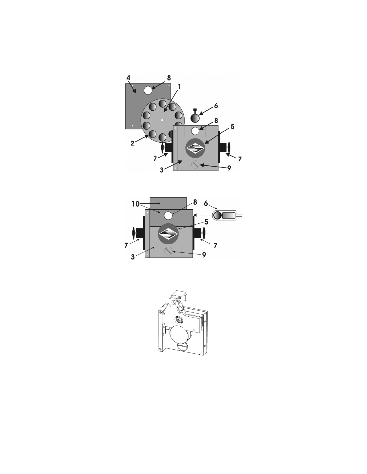
The basic components of the filter wheel mechanical assembly are shown in following figures.
The only components that are to be removed by the user are the drop-in or slide-in filter
holders and the plug in the loading port. At no time should the user remove the cover plate
from the wheel housing.
1. 10-position wheel (removed from motor hub)
2. Installed filter cup
3. Wheel housing
4. Cover plate (removed from wheel housing
5. Stepper motor
6. Drop-in filter holder (Figure 1-1) or slide-in filter holder (Figure 1-2)
7. Mounting ears
8. Optical port
LAMBDA 10-3 OPERATION MANUAL – REV. 3.03 (20110829)
Page 15
3
9. Loading port (plug installed)
10. Shutter housing
Figure 1-1. Lambda 10-3 filter wheel (without shutter).
Figure 1-2. Lambda 10-3 filter wheel housing (with shutter).
Figure 1-3. Lambda 10-3 filter wheel housing with SmartShutter.
1.3.2
1.3.2 Filter Wheels
Filter Wheels
1.3.21.3.2
Filter WheelsFilter Wheels
When a Lambda 10-3 Filter Wheel system is purchased, its configuration may include one
filter wheel, with or without a shutter. If the Lambda 10-3 system is purchased with a 10position 25mm (1-inch) filter wheel, you may wish to exchange the filter wheel with a 10position 32mm or a 5-position 50mm filter wheel. If the filter wheel being replaced is a 10position 32mm filter wheel equipped with a 35mm shutter (UNIBLITZ® or SmartShutter),
LAMBDA 10-3 OPERATION MANUAL – REV. 3.03 (20110829)
Page 16

4
then Lambda 10-3 controller must be modified by Sutter Instrument Co. before said filter
wheel with shutter is connected. If the 32mm filter wheel is not equipped with a shutter, or if
installing a 50mm filter wheel, then no modification to the Lambda 10-3 controller is needed.
Note that
Note that you must
Note that Note that
you must only
you mustyou must
only use filter wheels manufactured by Sutter Instrument Company.
onlyonly
use filter wheels manufactured by Sutter Instrument Company. All
use filter wheels manufactured by Sutter Instrument Company. use filter wheels manufactured by Sutter Instrument Company.
filter wheel options are listed in Sutter Instrument’s catalogue and web site
(http://www.sutter.com), and in the following list.
LB10
10
10----position, 25mm fil
position, 25mm filter wheels
1010
position, 25mm filposition, 25mm fil
4444----position, 25mm filter wheels:
position, 25mm filter wheels:
position, 25mm filter wheels:position, 25mm filter wheels:
10
10----position 32mm filter wheels:
position 32mm filter wheels:
1010
position 32mm filter wheels:position 32mm filter wheels:
5555----position 50mm filter wheel
position 50mm filter wheel::::
position 50mm filter wheelposition 50mm filter wheel
ter wheels::::
ter wheelster wheels
LB10----NW (without shutter)
LB10LB10
LB10
LB10----NWIQ (with 25mm SmartShutter (IQ25
LB10LB10
LB10
LB10----NWS (with UNIBLITZ® shutter)
LB10LB10
LB10
LB10----NWE (without shutter and set up for emission)
LB10LB10
LB10
LB10----WHS4 (without shutter)
LB10LB10
LB10
LB10----WHS4IQ (with SmartShut
LB10LB10
LB10
LB10----WHS4E (without shutter and set up for
LB10LB10
emission)
emission)
emission)emission)
LB10
LB10----W32 (without shutter)
LB10LB10
LB10
LB10----NW32IQ (with 35mm SmartShutter (IQ35
LB10LB10
LB10
LB10----W32S (with 35mm UNIBLITZ® shutter)
LB10LB10
LB10
LB10----W50 (without shu
LB10LB10
NW (without shutter)
NW (without shutter)NW (without shutter)
NWIQ (with 25mm SmartShutter (IQ25----W2))
NWIQ (with 25mm SmartShutter (IQ25NWIQ (with 25mm SmartShutter (IQ25
NWS (with UNIBLITZ® shutter)
NWS (with UNIBLITZ® shutter)NWS (with UNIBLITZ® shutter)
NWE (without shutter and set up for emission)
NWE (without shutter and set up for emission)NWE (without shutter and set up for emission)
WHS4 (without shutter)
WHS4 (without shutter)WHS4 (without shutter)
WHS4IQ (with SmartShutter)
WHS4IQ (with SmartShutWHS4IQ (with SmartShut
WHS4E (without shutter and set up for
WHS4E (without shutter and set up for WHS4E (without shutter and set up for
W32 (without shutter)
W32 (without shutter)W32 (without shutter)
NW32IQ (with 35mm SmartShutter (IQ35----W))
NW32IQ (with 35mm SmartShutter (IQ35NW32IQ (with 35mm SmartShutter (IQ35
W32S (with 35mm UNIBLITZ® shutter)
W32S (with 35mm UNIBLITZ® shutter)W32S (with 35mm UNIBLITZ® shutter)
W50 (without shutter).
W50 (without shuW50 (without shu
tter).
tter).tter).
ter)
ter)ter)
W2))
W2))W2))
W))
W))W))
1.3.2.1 Mechanical Description
The basic components of the filter wheel mechanical assembly are shown in following figures.
The only components that are to be removed by the user are the drop-in or slide-in filter
holders and the plug in the loading port. At no time should the user remove the cover plate
from the wheel housing.
1. 10-position wheel (removed from motor hub)
2. Installed filter cup
3. Wheel housing
4. Cover plate (removed from wheel housing
5. Stepper motor
6. Drop-in filter holder (Figure 1-1) or slide-in filter holder (Figure 1-2)
7. Mounting ears
8. Optical port
9. Loading port (plug installed)
10. Shutter housing
1.3.3
1.3.3 Filters
Filters
1.3.31.3.3
FiltersFilters
The Lambda 10-3 Controller can be used with a range of filter wheels. Most of these wheels
accept both 25 mm and 1-inch diameter filters. When larger filters are required, wheels are
available that accept 32 mm and 50 mm diameter filters.
LAMBDA 10-3 OPERATION MANUAL – REV. 3.03 (20110829)
Page 17

5
Filter wheels designed for use with 1 inch or 25 mm filters will accept filters with a thickness
that does not exceed the following dimensions:
4.5 mm (0.18 in.) for Slide
4.5 mm (0.18 in.) for Slide----in filter holders
4.5 mm (0.18 in.) for Slide4.5 mm (0.18 in.) for Slide
5.38 mm (0.21 in.) for Drop
5.38 mm (0.21 in.) for Drop----in filter holders
5.38 mm (0.21 in.) for Drop5.38 mm (0.21 in.) for Drop
9 mm (0.35 in.) for Filter cups
9 mm (0.35 in.) for Filter cups
9 mm (0.35 in.) for Filter cups9 mm (0.35 in.) for Filter cups
in filter holders
in filter holdersin filter holders
in filter holders
in filter holdersin filter holders
Filter wheels designed for use with 32 mm filters will accept filters with a thickness that does
not exceed the following dimensions:
9 mm (0.35 in.) for Filter cups
9 mm (0.35 in.) for Filter cups
9 mm (0.35 in.) for Filter cups9 mm (0.35 in.) for Filter cups
Instructions for installing filters into the filter wheel can be found in the FILTER WHEEL
chapter of this manual. Filters are not supplied by Sutter Instrument Company but filters
conforming to the above
conforming to the above specifications can be purchased from any filter manufacturer.
conforming to the above conforming to the above
1.3.4
1.3.4 Slide
Slide----in or Drop
1.3.41.3.4
in or Drop----in Filter Holders
SlideSlide
in or Dropin or Drop
Filters are not supplied by Sutter Instrument Company but filters
Filters are not supplied by Sutter Instrument Company but filters Filters are not supplied by Sutter Instrument Company but filters
specifications can be purchased from any filter manufacturer.
specifications can be purchased from any filter manufacturer.specifications can be purchased from any filter manufacturer.
in Filter Holders
in Filter Holdersin Filter Holders
Many users prefer having extra Slide-in or Drop-in filter holders for more convenient
replacement of these “fixed” filters. Only use filter holders made by Sutter Instrument
Company in the Lambda 10
Company in the Lambda 10----3 Filter Wheel.
Company in the Lambda 10Company in the Lambda 10
3 Filter Wheel. Extra filter holders for one-inch wheels are
3 Filter Wheel. 3 Filter Wheel.
Only use filter holders made by Sutter Instrument
Only use filter holders made by Sutter Instrument Only use filter holders made by Sutter Instrument
readily available from Sutter Instrument Company or their distributors and are listed as
“SLIDE-IN” and “DROP-IN” in the Sutter catalogue. At this point, there are no slide-in
filter holders for 32 mm systems, although a 32-mm Drop-in filter holder is available. In
addition, there is a fixed filter position for a heat-blocking filter in most 32-mm microscope
adapters offered by Sutter Instrument Company. Slide-in and drop-in filter holders are not
available for the 50 mm filter wheels.
1.3.5
1.3.5 Shutters
Shutters
1.3.51.3.5
ShuttersShutters
If you purchase a Lambda 10-3 Filter Wheel system without a shutter and later decide to add
one to the system, the Filter Wheel must be returned to the factory for the upgrade. The
current version of the Lambda 10-3 Filter Wheel controller can support a retrofit with a
SmartShutter or traditional shutter, without modification. The installation of a traditional
shutter may require the setting of a jumper to configure the driver circuit for the size of
shutter installed. You must
contact Sutter Instrument Company or your distributor for details
contact Sutter Instrument Company or your distributor for details.
contact Sutter Instrument Company or your distributor for detailscontact Sutter Instrument Company or your distributor for details
You must only use shutters installed by Sutter Instrument Company
You must You must
only use shutters installed by Sutter Instrument Company --
only use shutters installed by Sutter Instrument Company only use shutters installed by Sutter Instrument Company
--
----
In addition to the shutters that are integrated with filter wheels listed previously under
“Filter Wheels”, the following SmartShutters are supported by the Lambda 10-3:
IQ12
IQ12----SA
SA 12.5mm SmartShutter™ with stand-alone housing
IQ12IQ12
SASA
IQ25
IQ25----SA1
SA1 25mm SmartShutter™ with stand-alone housing
IQ25IQ25
SA1SA1
IQ25
IQ25----LS
LS 25mm SmartShutter™ with housing to fit Lambda LS
IQ25IQ25
LSLS
IQ25
IQ25----DG
DG 25mm SmartShutter™ with housing to fit Lambda DG-4/DG-5
IQ25IQ25
DGDG
IQ35
IQ35----SA
SA 35mm SmartShutter™ with stand-alone housing
IQ35IQ35
SASA
IQ50
IQ50----SA
SA 50mm SmartShutter™ with stand-alone housing
IQ50IQ50
SASA
NOTE: Where vignetting may be an issue in a 25mm optical pathway environment, a 35mm
NOTE: Where vignetting may be an issue in a 25mm optical pathway environment, a 35mm
NOTE: Where vignetting may be an issue in a 25mm optical pathway environment, a 35mm NOTE: Where vignetting may be an issue in a 25mm optical pathway environment, a 35mm
SmartShutter is recommended.
SmartShutter is recommended.
SmartShutter is recommended.SmartShutter is recommended.
LAMBDA 10-3 OPERATION MANUAL – REV. 3.03 (20110829)
Page 18

6
1.3.6
1.3.6 SmartShutter Mounts
SmartShutter Mounts
1.3.61.3.6
SmartShutter MountsSmartShutter Mounts
An 8-32 screw-mount hole exists on the edge of the SmartShutter opposite the motor, into
which may be attached a mounting post of any desired length. When the SmartShutter is
mounted on a post using this screw-mount hole, the exact center of the shutter aperture is
precisely aligned with the vertical center of the post. Posts of various lengths are available
from Sutter Instrument Co. This post, along with posts of other dimensions, as well as post
holders and bases, are available from most laboratory equipment suppliers.
A SmartShutter can also be mounted on a Sutter Instrument Co. Filter Wheel with a special
enclosure, as well as with other Sutter Instrument Co. products, such as the Lambda LS,
Lambda DG-4, Lambda DG-5, and various Lambda 10 series Filter Wheel controllers. Please
consult with Sutter Instrument Co.’s Technical Support for the different configuration
possibilities.
1.3.7
1.3.7 Cables
Cables
1.3.71.3.7
CablesCables
A special cable is required for connecting a standalone SmartShutter to Ports A and B of the
Lambda 10-3. The CIQ-2 cable is a split cable consisting of one DB-25 connector at the main
end (for connecting to the “SmartShutter” connector A or B on the rear of the Lambda 10-3
cabinet) and a DB-9 connector at each of the split ends. One split end is shorter than the
other. When connecting a single standalone SmartShutter to the Lambda 10-3 Port A or B,
the SmartShutter connects to the DB-9 connector of the longer split, and a terminator is
required to be attached to the DB-9 connector of the shorter split.
NOTE: Dual SmartShutters connected with the CIQ
NOTE: Dual SmartShutters connected with the CIQ----2
NOTE: Dual SmartShutters connected with the CIQNOTE: Dual SmartShutters connected with the CIQ
not supported. However, the CIQ
not supported. However, the CIQ----2 cable can be used to connect a single standalone
not supported. However, the CIQnot supported. However, the CIQ
SmartShutter to the 25
SmartShutter to the 25----pin “SmartShutter” connector f
SmartShutter to the 25SmartShutter to the 25
pin “SmartShutter” connector for port bay A or B.
pin “SmartShutter” connector fpin “SmartShutter” connector f
2 cable can be used to connect a single standalone
2 cable can be used to connect a single standalone 2 cable can be used to connect a single standalone
2 cable connected to the Lambda 10
cable connected to the Lambda 10----3 is
2 2
cable connected to the Lambda 10cable connected to the Lambda 10
or port bay A or B.
or port bay A or B.or port bay A or B.
3 is
3 is 3 is
When connecting a standalone SmartShutter to a correctly-configured Port C of the Lambda
10-3, only a standard DB-9-to-DB-9 cable is required. Note that older generations of the
Lambda 10-3 do not support a shutter on Port C.
1.3.8
1.3.8 Devices fo
Devices for TTL
1.3.81.3.8
Devices foDevices fo
r TTL----Control of Shutters
r TTLr TTL
Control of Shutters
Control of ShuttersControl of Shutters
Two devices are available from Sutter Instrument for the TTL control of shutters that are
attached to the Lambda 10-3.
FSWITCH:
FSWITCH: A foot switch with BNC connector. It changes the ON/OFF state of the
FSWITCH:FSWITCH:
shutter with each foot press. The state is maintained as long as the switch
remains depressed.
FSTOGGLE:
FSTOGGLE:
FSTOGGLE:FSTOGGLE:
Adapters
Adapters
AdaptersAdapters
Like the FSWITCH, but alternates the ON/OFF state with each foot press.
Most microscopes, cameras, light sources and other optical instruments to which the Lambda
10-3 Filter Wheel may be interfaced will require some sort of adapter to link the devices.
Adapters for interfacing the Filter Wheel to most instruments are available from Sutter
Instrument Company or can be custom built by Sutter Instrument. Suitable adapters are
available from other sources, as well, but Sutter Instrument Company assumes no
available from other sources, as well, but Sutter Instrument Company assumes no
available from other sources, as well, but Sutter Instrument Company assumes no available from other sources, as well, but Sutter Instrument Company assumes no
responsibility for the performance, suitability, and safety of adapters built by the user or
responsibility for the performance, suitability, and safety of adapters built by the user or
responsibility for the performance, suitability, and safety of adapters built by the user or responsibility for the performance, suitability, and safety of adapters built by the user or
other manufacturers.
other manufacturers.
other manufacturers.other manufacturers.
Suitable adapters are
Suitable adapters are Suitable adapters are
LAMBDA 10-3 OPERATION MANUAL – REV. 3.03 (20110829)
Page 19

7
1.4
1.4 SmartShutter
SmartShutter
1.41.4
SmartShutterSmartShutter
The SmartShutter is a lightweight motor-driven aluminum vane under microprocessor
control. Because of the microprocessor control, the motion of the vane can be tailored for
different roles. The vane starts and stops under motor control, eliminating the sharp jolt
typical of other fast shutters.
1.4.1
1.4.1 Step Motor Based Shutter Advantages
Step Motor Based Shutter Advantages
1.4.11.4.1
Step Motor Based Shutter AdvantagesStep Motor Based Shutter Advantages
The new step motor-based shutter is made from a handful of parts, any of which can be
replaced if it fails. The speed of opening and closing of the shutter is practically the same as
the traditional shutters, and the mechanism is more robust. The shutter blade is stopped by
action of the motor rather than by mechanical stops that might fail. Because the motion
profile of the shutter is controlled by a microprocessor, the motion can be optimized for speed
or for smoothness. The microprocessor-based controller also offers the potential for a very
adaptable controller, which could include additional functions and modes of operation. If the
electronics fail, the motor can be disconnected and the blade set open or closed by hand.
Operation does not require over-driving the windings, so it can maintain operation at up to
40 Hz continuously. The unit can operate on modest voltages, which are typically available in
the Lambda 10 series controllers. The package size is comparable to the traditional shutters
and can be customized when needed.
Another advantage of step motor-based shutter is the ability to control the aperture of
shutter blade in its opened state. This mode is called Neutral Density and is used to control
the intensity of the light coming through the opened shutter without affecting the light’s
wavelength. The neutral density aperture size of the shutter is determined by the number of
microsteps (1 through 144) specified for the motor to open the shutter.
The following instructions describe how to set up the Lambda SmartShutter and selecting
filters in manual mode. More detailed discussions on the controller functions, installing
filters, and remote communications are found in other sections of this manual.
LAMBDA 10-3 OPERATION MANUAL – REV. 3.03 (20110829)
Page 20
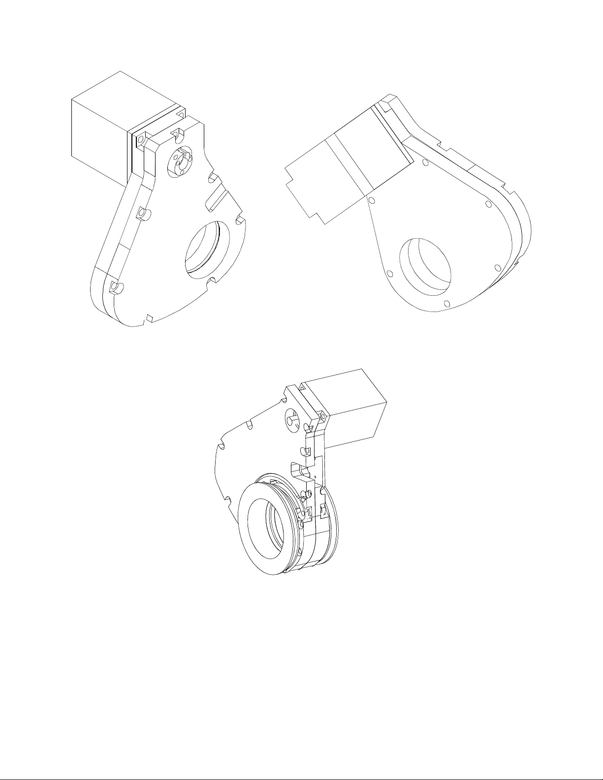
8
Figure 1-4. 25mm SmartShutter (standalone).
Figure 1-5. 35mm SmartShutter (standalone).
LAMBDA 10-3 OPERATION MANUAL – REV. 3.03 (20110829)
Page 21
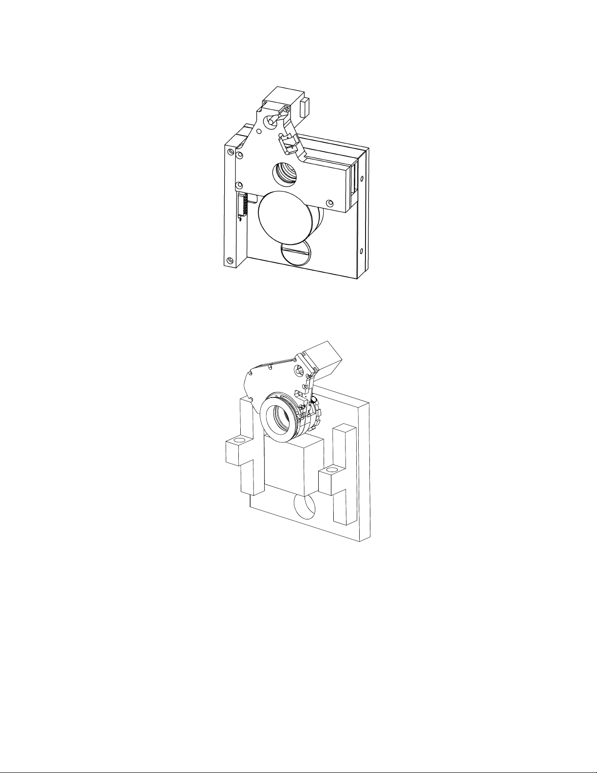
9
Figure 1-6. 25mm SmartShutter mounted on the housing of a 25mm Filter Wheel.
The following figure shows a 35mm SmartShutter mounted on a 32mm Filter Wheel housing.
Figure 1-7. 35mm SmartShutter mounted on 32mm Filter Wheel Assembly.
1.4.2
1.4.2 Modes
Modes
1.4.21.4.2
ModesModes
The Lambda 10-3 supports three modes of operation for the SmartShutter.
Fast Mode:
In the fast mode the motion is optimized for the fastest open and close times,
both of which will be about 8 msec.
Soft Mode:
The soft mode offers even less vibration at the expense of slower open and
close times.
LAMBDA 10-3 OPERATION MANUAL – REV. 3.03 (20110829)
Page 22

10
Neutral Density Mode:
In this mode the user selects the extent to which the shutter
opens. When used with the Sutter Instrument light guide system (LLG), this allows the
light output from the light guide to be attenuated without changing its wavelength or
spatial distribution. The value for opening can be selected in steps from 1 (no opening) to
144 (complete opening).
1.4.3
1.4.3 Special Considerations
Special Considerations
1.4.31.4.3
Special ConsiderationsSpecial Considerations
The new step motor-based SmartShutter is made from a handful of parts, any of which can
be replaced for service. The SmartShutter can open or close in about 8 msec...., and the
mechanism is robust. The shutter blade is stopped by action of the motor rather than by
mechanical stops that might fail. Because the motion profile of the shutter is controlled by a
microprocessor, the motion can be optimized for speed or for smoothness. The
microprocessor-based controller also offers additional functions and modes of operation. If
the electronics fail, the motor can be disconnected and the blade set open or closed by hand.
1.4.3.1 Mounting
When a 25 mm SmartShutter is to be mounted to a Lambda 10 filter wheel, a special version
of the SmartShutter is supplied which will attach directly to the slide-in filter housing. The
C-mount threads in the SmartShutter housing will accept the standard Sutter microscope
adapters.
When a 35 mm SmartShutter is mounted to a 32 mm Lambda 10 series filter wheel, a special
adapter threads into the filter wheel T-mount, on to which the SmartShutter is mounted.
The 35 mm SmartShutter has a receptacle for the flange on the end of this T-mount tube and
this allows the SmartShutter to mount to the flange on the end of the tube in many different
orientations. On the other side of the SmartShutter a similar rotating mount accepts an
adapter that is used to couple to our standard microscope adapters. It is possible to install a
T-mount instead, if desired.
1.4.3.2 Opening and Closing Times
The SmartShutter has a typical time to open of 8 milliseconds, from the point a complete
command or TTL signal is received. The time to close is also eight milliseconds. This is true
for both the 25 mm and the 35 mm versions operating in the fast mode. Note that the
controller will not accept new commands or TTL pulses in the FAST mode for about 12 msec
after a command has been received. The additional time is required for display changes and
other overhead.
LAMBDA 10-3 OPERATION MANUAL – REV. 3.03 (20110829)
Page 23
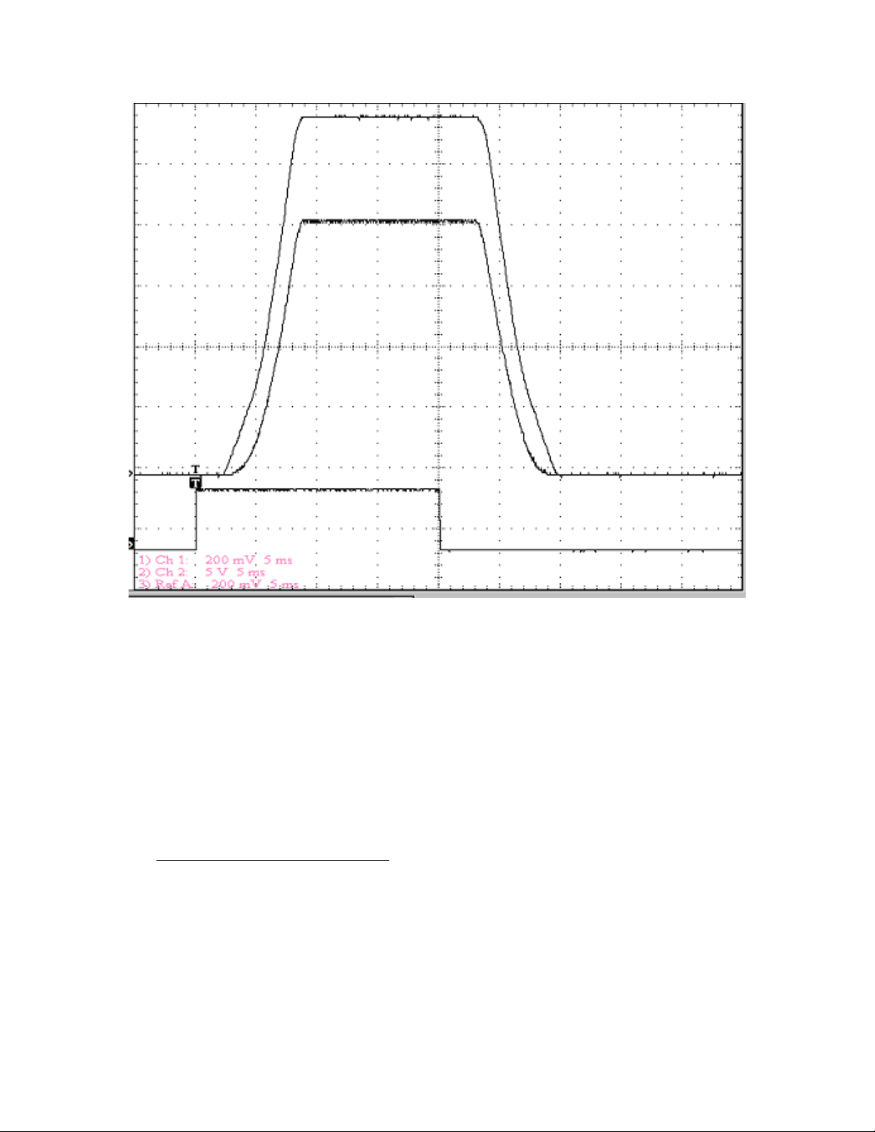
11
Figure 1-8. SmartShutter timing.
The timing of a
SmartShutter is shown in the figure above. The bottom trace is a TTL signal,
the middle trace is a 25 mm SmartShutter, and the upper trace is a 35 mm SmartShutter.
Operation is slower in the ND (Neutral Density) and SOFT modes. In the SOFT mode, the
SmartShutter has a typical time to open of 60 msec. from the point a complete command or
TTL signal is received. The time to close is also 60 msec. This is true for both the 25 mm and
the 35 mm versions. In the ND mode, the time to open and the time to close will depend on
the number of steps selected. For a complete opening of 144 steps, the time to open and the
time to close will each be about 38 msec. The time required will be approximately
proportional to the number of steps, or about 2.6 msec per 10 steps.
1.4.3.3 Repetition Rates and Duty Cycle
Operation does not require over-driving the motor windings, so the motor windings are not
damaged by frequent opening and closing over long time periods. 25 mm (one inch) versions
can usually operate well at up to 20 Hz. 35 mm versions can usually operate well at up to 15
Hz. These shutters may be operated at higher rates up to 40 Hz, but there will normally be
specific frequencies in the higher ranges that will produce errors in motion of the shutter
blade. This is the result of resonances in the mechanical and electrical systems.
If the duty cycle is substantially different from 50%, errors in movement may occur at lower
frequencies. At 40 Hz, the cycle time is 25 msec., with 12.5 msec. between open and close
LAMBDA 10-3 OPERATION MANUAL – REV. 3.03 (20110829)
Page 24
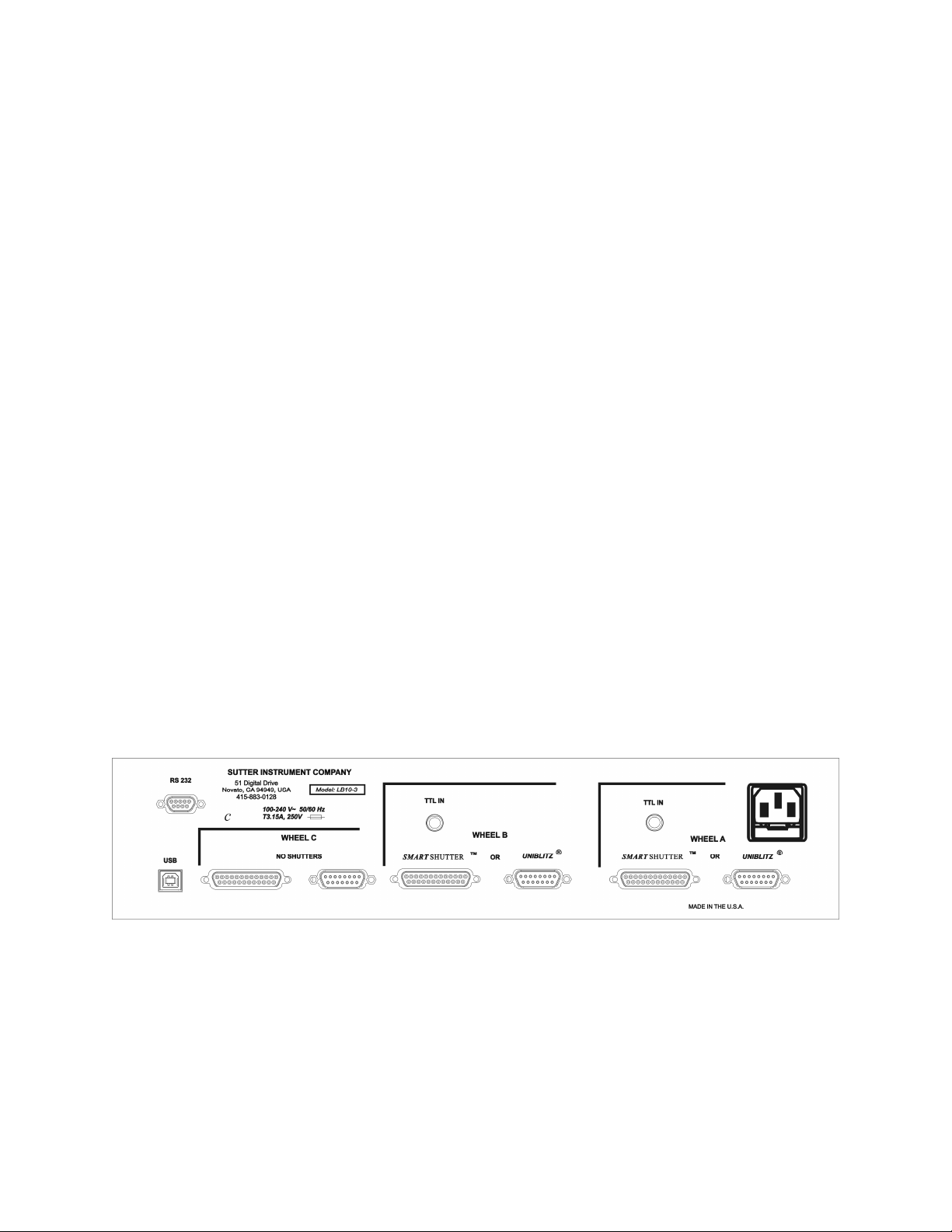
12
commands. This is close to the absolute minimum time in either the open or closed state. If
you attempt to reduce the time in either state below 12 msec, the controller will not start to
change the shutter state until the 12-msec minimum period is over.
1.5
1.5 Controller
Controller
1.51.5
ControllerController
1.5.1
1.5.1 Principles of Operation
Principles of Operation
1.5.11.5.1
Principles of OperationPrinciples of Operation
The Lambda 10-3 controller can be operated locally (manually) from the controller keypad or
remotely from a computer either through the serial, USB, or parallel port. These four
operational modes (manual, USB and serial) are functionally identical. Each allows the user
to select:
Filter Wheel
Filter position
Filter switching speed
Shutter position
Shutter mode
The remainder of this chapter provides a detailed description of the controller’s rear panel
connectors and front panel controls. Information needed to connect the power cord and filter
wheel(s) is found in the FIRST TIME USE chapter. Instructions on operation of the
controller and manual keypad control of the filter wheel(s) are presented in the MANUAL
CONTROL chapter. The REMOTE CONTROL chapter explains control of the unit from a
remote device, as well as supplying some technical details relevant to local operation.
Technical details, which are not required for operation but which may help you understand
the behavior of the unit, are found in APPENDIX A: Stepping Motor Operation.
1.5.2
1.5.2 Rear Panel Connectors
Rear Panel Connectors
1.5.21.5.2
Rear Panel ConnectorsRear Panel Connectors
All electrical connections are all made on the rear panel of the Lambda 10-3. See the FIRST
TIME USE chapter for details on connecting the power cord and filter wheel cable(s).
Figure 1-9. Generation 1 rear panel electrical connections.
LAMBDA 10-3 OPERATION MANUAL – REV. 3.03 (20110829)
Page 25
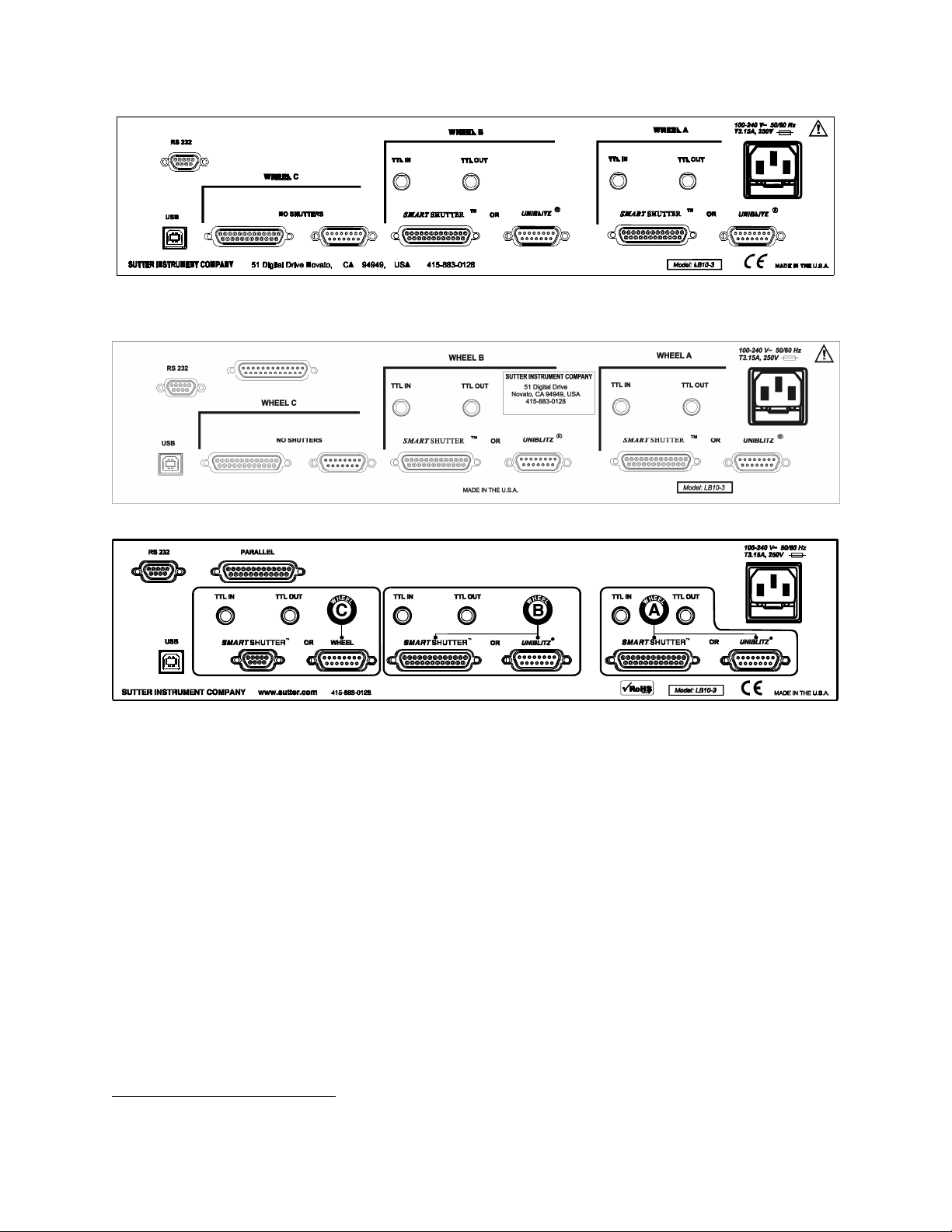
13
Figure 1-10. Generation 2 rear panel electrical connections
.
Figure 1-11. Generation 3 rear panel electrical connections).
Figure 1-12. Generation 4 rear panel electrical connections.
WHEEL A
WHEEL A (Gen 1
WHEEL AWHEEL A
(Gen 1 –––– 3) or A (Gen 4)
(Gen 1 (Gen 1
SMART
SMART
SMARTSMART
3) or A (Gen 4)
3) or A (Gen 4) 3) or A (Gen 4)
SHUTTER:
SHUTTER: This 25-pin DSUB connector is used to interface with a filter
SHUTTER:SHUTTER:
wheel that has an integrated SmartShutter or a standalone SmartShutter.
UNIBLITZ
UNIBLITZ
UNIBLITZUNIBLITZ
®®®®
:
: This 15-pin DSUB connector is used to interface with a filter wheel that
: :
is either standalone (has no integrated shutter) or one that has an integrated
Uniblitz®1 shutter.
TTL IN:
TTL IN: This BNC connector is used optionally for interfacing with a TTL-triggering
TTL IN:TTL IN:
device that controls the opening and closing control of Shutter A (Uniblitz or
SmartShutter).
TTL OUT:
TTL OUT: This BNC connector is used optionally to relay out to another device the
TTL OUT:TTL OUT:
TTL signaling coming in on TTL IN.
NOTE:
NOTE: A standalone filter wheel (one
NOTE: NOTE:
shutter) can be attached to the 15
shutter) can be attached to the 15----pin connector at the same time as a standalone
shutter) can be attached to the 15shutter) can be attached to the 15
1
Uniblitz is a registered trademark of Vincent Associates.
A standalone filter wheel (one that
A standalone filter wheel (one A standalone filter wheel (one
that is not equipped with an integrated
is not equipped with an integrated
thatthat
is not equipped with an integrated is not equipped with an integrated
pin connector at the same time as a standalone
pin connector at the same time as a standalone pin connector at the same time as a standalone
LAMBDA 10-3 OPERATION MANUAL – REV. 3.03 (20110829)
Page 26

14
SmartShutter is attached to the 25
SmartShutter is attached to the 25----pin connector. Do not attempt to attach two filter
SmartShutter is attached to the 25SmartShutter is attached to the 25
wheels to the Wheel A set of connectors.
wheels to the Wheel A set of connectors.
wheels to the Wheel A set of connectors.wheels to the Wheel A set of connectors.
WHEEL B
WHEEL B (Gen 1
WHEEL BWHEEL B
(Gen 1 –––– 3) or B (Gen 4)
(Gen 1 (Gen 1
The connectors for WHEEL B are provided for interfacing with a second filter wheel
and/or shutter, and have the same functionality as those for WHEEL A..
WHEEL C (
WHEEL C (Gen 1
WHEEL C (WHEEL C (
Gen 1 –––– 3)
Gen 1 Gen 1
Only a filter wheel can be connected as Wheel C. The connectors for Wheel C cannot
be used for shutters (as part of the filter wheel or standalone). If a filter wheel that is
equipped with an integrated shutter is attached as Wheel C, the integrated shutter
will be non-functional.
NOTE
NOTE 1
NOTENOTE
NOTE 2: If the filter wheel is connected to the 15
NOTE 2: If the filter wheel is connected to the 15----pin connector and has an integrated
NOTE 2: If the filter wheel is connected to the 15NOTE 2: If the filter wheel is connected to the 15
UNIBLITZ shutte
UNIBLITZ shutter, the shutter will be nonfunctional.
UNIBLITZ shutteUNIBLITZ shutte
1:
: Do not attempt to attach two filter wheels to the Wheel C set of connectors.
Do not attempt to attach two filter wheels to the Wheel C set of connectors.
1 1
: :
Do not attempt to attach two filter wheels to the Wheel C set of connectors.Do not attempt to attach two filter wheels to the Wheel C set of connectors.
pin connector. Do not attempt to attach two filter
pin connector. Do not attempt to attach two filter pin connector. Do not attempt to attach two filter
3) or B (Gen 4)
3) or B (Gen 4) 3) or B (Gen 4)
3)
3) 3)
r, the shutter will be nonfunctional.
r, the shutter will be nonfunctional.r, the shutter will be nonfunctional.
pin connector and has an integrated
pin connector and has an integrated pin connector and has an integrated
NOTE 3: If the filter wheel is connected to the 25
C (
C (Gen
Gen 4444))))
C (C (
GenGen
NOTE 3: If the filter wheel is connected to the 25----pin connector and has an integrated
NOTE 3: If the filter wheel is connected to the 25NOTE 3: If the filter wheel is connected to the 25
SmartShutter, the SmartShutter will be nonfunctional.
SmartShutter, the SmartShutter will be nonfunctional.
SmartShutter, the SmartShutter will be nonfunctional.SmartShutter, the SmartShutter will be nonfunctional.
pin connector and has an integrated
pin connector and has an integrated pin connector and has an integrated
This port array is configurable to support either a standalone filter wheel or a
standalone SmartShutter.
NOTE
NOTE 1
NOTENOTE
same time, only one or the other will be functional according to how the Lambda 10
same time, only one or the other will be functional according to how the Lambda 10----3
same time, only one or the other will be functional according to how the Lambda 10same time, only one or the other will be functional according to how the Lambda 10
is configured.
is configured.
is configured.is configured.
NOTE 2: If the connected filter whe
NOTE 2: If the connected filter wheel is equipped with a UNIBLITZ shutter, the
NOTE 2: If the connected filter wheNOTE 2: If the connected filter whe
shutter will be nonfunctional.
shutter will be nonfunctional.
shutter will be nonfunctional.shutter will be nonfunctional.
NOTE 3: A standalone SmartShutter is connected to the SMARTSHUTTER
NOTE 3: A standalone SmartShutter is connected to the SMARTSHUTTER
NOTE 3: A standalone SmartShutter is connected to the SMARTSHUTTER NOTE 3: A standalone SmartShutter is connected to the SMARTSHUTTER
connector via
connector via a cable with 9
connector via connector via
1:
: If both a standalone filter wheel and a SmartShutter are connected at the
If both a standalone filter wheel and a SmartShutter are connected at the
1 1
: :
If both a standalone filter wheel and a SmartShutter are connected at the If both a standalone filter wheel and a SmartShutter are connected at the
el is equipped with a UNIBLITZ shutter, the
el is equipped with a UNIBLITZ shutter, the el is equipped with a UNIBLITZ shutter, the
a cable with 9----pin D
a cable with 9a cable with 9
pin D----SHELL connectors at each end.
pin Dpin D
SHELL connectors at each end.
SHELL connectors at each end.SHELL connectors at each end.
USB PORT:
USB PORT: This is a B type USB connector, which allows connection to a host computer
USB PORT: USB PORT:
USB port.
SERIAL PORT
SERIAL PORT: This 9 pin, DSUB connector is used for establishing a serial interface
SERIAL PORTSERIAL PORT
between the Lambda 10-3 and a remote device (computer) using the cable provided.
3
3 3
PARALLEL POR
PARALLEL PORTTTT: This 25 pin, DSUB connector is used for establishing a parallel interface
PARALLEL PORPARALLEL POR
between the Lambda 10-3 and a remote device (computer) using the cable provided.
LINE POWER
LINE POWER: This socket is used to connect the power cord to the Lambda 10-3.
LINE POWERLINE POWER
FUSE LABEL
FUSE LABEL: Information found here includes the model number of this instrument,
FUSE LABELFUSE LABEL
appropriate supply voltage, and the type of fuse required for the supply voltage.
LAMBDA 10-3 OPERATION MANUAL – REV. 3.03 (20110829)
Page 27
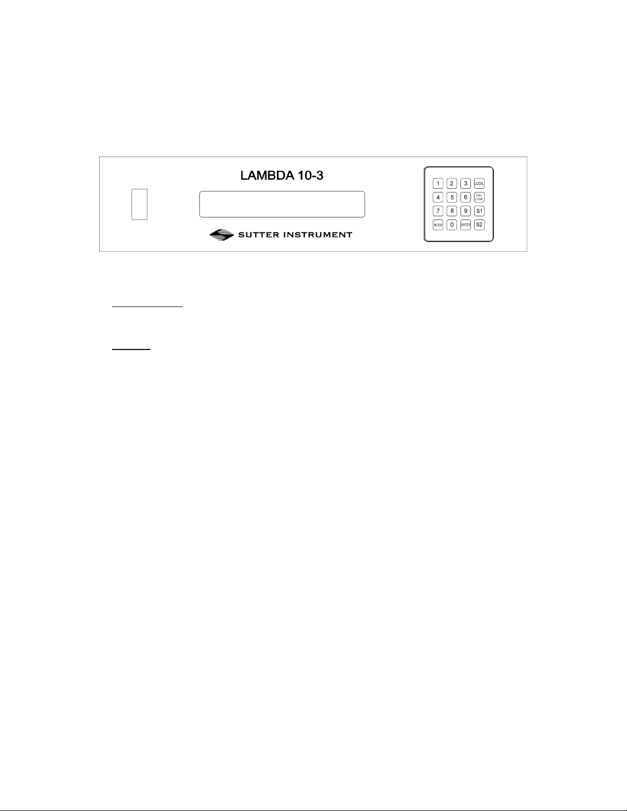
15
FUSE
FUSE: Fuse compartment containing the supply voltage fuse and an extra fuse. Replace
FUSEFUSE
blown fuses with a fuse of the appropriate value as given on the fuse label (back panel of the
controller) or on the TECHNICAL SPECIFICATIONS page in this manual.
1.5.3
1.5.3 Front Panel Controls
Front Panel Controls
1.5.31.5.3
Front Panel ControlsFront Panel Controls
Figure 1-13. Lambda 10-3 front panel controls.
1.5.3.1 Power Switch
This turns on the system power.
1.5.3.2 Keypad
There are 16 keys on the Lambda 10-3 keypad.
Numerical keys 0 to 9:
Numerical keys 0 to 9: These keys manually select filter positions and, via the MODE key,
Numerical keys 0 to 9:Numerical keys 0 to 9:
choose between the eight pre-set filter wheel speeds. During menu navigation, the 0 key
causes a return to the main display.
LOCAL:
LOCAL: Takes the controller off-line (for manual operation via the controller’s front-panel
LOCAL:LOCAL:
keypad and display).
ON LINE:
ON LINE: Puts the controller on-line (for remote control from a host computer connected
ON LINE:ON LINE:
via RS-232 serial or USB).
S1:
S1: Open/close Shutter A.
S1:S1:
S2:
S2: Open/close Shutter B.
S2:S2:
MODE:
MODE: Invokes a menu structure, allowing for the setting of the following:
MODE:MODE:
• Set active filter wheel.
Set active filter wheel.
Set active filter wheel.Set active filter wheel.
• Select filter wheel speed.
Select filter wheel speed.
Select filter wheel speed.Select filter wheel speed.
• Select shutter TTL control.
Select shutter TTL control.
Select shutter TTL control.Select shutter TTL control.
• Select among various test modes.
Select among various test modes.
Select among various test modes.Select among various test modes.
• Select operation modes of the SmartShutters.
Select operation modes of the SmartShutters.
Select operation modes of the SmartShutters.Select operation modes of the SmartShutters.
• Save and restore SmartShutter mode configurations.
Save and restore SmartShutter mode configurations.
Save and restore SmartShutter mode configurations.Save and restore SmartShutter mode configurations.
ENTER:
ENTER: Used to navigate menus and for the entering of values from the keypad.
ENTER:ENTER:
While a key is depressed, the controller detects its functionality. However, the controller will
not act upon the functionality indicated by a depressed key until released. A key that is
pressed while a move is in progress but released after the move is over will cause the action
LAMBDA 10-3 OPERATION MANUAL – REV. 3.03 (20110829)
Page 28

16
associated with that key to occur normally. Keys pressed and released while a move is in
progress are ignored.
1.5.3.3 Display
When the controller is switched (powered) on, the controller homes all the attached filter
wheels and activate all the attached shutters. During this initialization process, the following
is displayed on the controller’s display.
FILTER WHEEL CONTROLLER PROGRAM V1.21
COPYRIGHT SUTTER INSTRUMENT CORP 2004
After the controller has finished initializing, the status screen is displayed.
WHEEL: A-25MM 0 1 B-NC C-NC U
SHUTR: A- OFF B-FAST OFF
The first line of the status screen indicates which of the three possible filter wheels are
connected, what their respective sizes are, and the position and speed setting of each. “NC” is
shown for a channel to which no filter wheel is attached. At the end of the first line is a
character which indicates online/offline status of the controller (online is indicated by “U” if
the USB interface is in control or “S” for the serial interface. “L” indicates local (offline)
mode, allowing for keypad control).
The second line of the status screen shows the opened/closed state of the two possible
shutters that can be attached to the controller. When an attached shutter is a SmartShutter,
its mode is also shown.
See the next chapter for a detailed description of how to control the controller locally via the
keypad and how to navigate through the various menus shown on the controller’s front-panel
display.
1.6
1.6 Options and Accessories
Options and Accessories
1.61.6
Options and AccessoriesOptions and Accessories
1.6.1
1.6.1 Supported Filter Wheel and Shutter Configurations
Supported Filter Wheel and Shutter Configurations
1.6.11.6.1
Supported Filter Wheel and Shutter ConfigurationsSupported Filter Wheel and Shutter Configurations
The Lambda 10-3 controller provides three port bays (A, B, and C) each to which can be
connected a filter wheel and/or shutter.
1. Port Bays AAAA and BBBB each supports the following:
A filter wheel with integrated shutter (SmartShutter or UNIBLITZ®2)
A standalone filter wheel (no integrated shutter)
A standalone SmartShutter (no filter wheel)
A standalone filter wheel and a standalone SmartShutter
2
UNIBLITZ is a registered trademark of Vincent Associates.
LAMBDA 10-3 OPERATION MANUAL – REV. 3.03 (20110829)
Page 29

17
2. Port Bay CCCC supports one standalone filter wheel. No shutter support is provided. A filter
wheel with integrated shutter can be connected to Port Bay C, but the shutter will be
inoperative.
1.7
1.7 Functional Description
Functional Description
1.71.7
Functional DescriptionFunctional Description
1.7.1
1.7.1 Stepping Motor Operation
Stepping Motor Operation
1.7.11.7.1
Stepping Motor OperationStepping Motor Operation
Stepping motors are not as familiar to most people as the common DC motor, but there are
some similarities. The DC motor consists of an armature, an electromagnet mounted on a
rotating shaft, which is located inside a permanent magnet. Current is supplied to the
electromagnet through brushes that rub on contacts on the armature. When the
electromagnet is energized, the armature rotates to align the poles of the electromagnet with
the opposite poles of the permanent magnet. Of course, before this can occur, the rotation of
the armature changes the contact plates rubbing on the brushes so that the current is
reversed. This causes the poles of the electromagnet to reverse, establishing a force for
continued rotation. This switching action is called commutation.
In stepping motors, the rotating element, called a rotor, is generally a permanent magnet
while the fixed element, the stator, is the electromagnet. The key difference between
stepping motors and DC motors, however, is the method of commutation. The DC motor
commutates automatically as it rotates. Thus, the timing of the commutation is determined
by the speed of rotation, which may vary with the load or applied power. The commutation of
the stepping motor is set by external electronics, forcing the motor to rotate at a
predetermined rate. If the load is such that the motor does not have the force to produce the
correct rate of rotation, the rotation will become erratic and may even reverse.
The force exerted between two magnet poles is proportional to the square of the distance
between the poles. A motor with a single electromagnet and only two poles would exhibit
considerable loss of power when the distance between the poles of the permanent magnet and
the electromagnet was greatest. It is understandable that, in most practical DC motors, the
armature has more than 2 poles. This allows the commutation to occur over a smaller angle
of rotation, so that the active poles can always be relatively close to the poles of the
permanent magnet.
Stepping motors are also made with multiple poles on both the rotor and stator; the exact
arrangement determines the number of steps per revolution. The motor used in the Lambda
10-3 has 200 steps per revolution (1.8 degrees per step). There are usually two windings in
the stator, and reversing the current on one of the windings produces a single step of
rotation. Reversing the current on the second winding will then produce another step. If the
first winding is then reversed again, returning to its original value, a third step will result.
Finally, reversing the second winding, so that both windings are back to their original state,
will produce a fourth step. This pattern may then be repeated to continue rotation in the
same direction. Reversing the sequence produces steps of rotation in the opposite direction.
The rate and distance of rotation is determined by the rate and number of commutation
steps. As long as the current is held constant in both windings, the rotor will not rotate. This
makes the stepping motor ideal for producing fast start and stop movements. Some
limitations should be considered. Given that there are only 4 states of the control electronics
(2 polarities for each of the 2 windings) but 200 steps per revolution, it follows that, for each
of these 4 states, there are 50 possible rotary positions. In order to establish the absolute
LAMBDA 10-3 OPERATION MANUAL – REV. 3.03 (20110829)
Page 30

18
position an external sensor must be added. Absolute position only needs to be determined
once so long as the subsequent moves occur without errors.
Correct operation of stepping motors, which is outlined above, is not always obtained. If the
motor lacks the torque to accelerate and decelerate the load at the rate indicated by the
control electronics, the resulting move may differ from that commanded by the control
electronics. For instance, if enough external force is applied, the motor shaft may be rotated
even though the command signal has not changed. For small rotations (less than 3.6
degrees), the motor shaft will return to the correct position if the force is removed. For larger
rotations, the shaft will stop at the nearest of the 50 correct positions for that command
signal when the external force is removed.
LAMBDA 10-3 OPERATION MANUAL – REV. 3.03 (20110829)
Page 31

19
2.
2. I NSTA LLAT IO
INST ALLA TIO NNNN
2.2.
INST ALLA TIOI N STA L LAT I O
2.1
2.1 Unpacking
Unpacking
2.12.1
UnpackingUnpacking
The Lambda 10-3 and associated hardware comes packed in a single carton. The following is
a list of the components found there. If you believe that any of these components are missing
or show obvious signs of damage from shipping, please contact the factory.
One, two, or three filter wheels, each with or without a shutter (UNIBLITZ or
SmartShutter).
Optionally, one or two SmartShutters, each either standalone or mounted on a filter
wheel.
LAMBDA 10-3 controller.
Support base (one for each filter wheel).
Two support rods (one set for each filter wheel).
Two base clamps (one set for each filter wheel).
For each standalone 25mm SmartShutter, a mounting rod and base holder are included if
ordered.
Filter wheel to controller connecting cable (one for each filter wheel).
• A 15-pin cable is used for filter wheels without a shutter mounted or with a
UNIBLITZ1 shutter mounted.
• A 25-pin cable is used for filter wheels with a SmartShutter mounted.
• If a standalone filter wheel and a standalone Smart Shutter are to be connected to the
same port, there are two ways in which cabling can be accomplished:
A split cable can be used that has a 25-pin connector at one end (for the controller
port), the other end of which splits to a 15-pin cable/connector for the filter wheel
and 9-pin cable/connector for the SmartShutter.
A 15-pin cable can be used for the filter wheel and a 25-pin to 9-pin cable can be used
for the SmartShutter.
For each standalone SmartShutter included in your shipment, either a 25-pin to 9-pin
cable, or one of the cables listed previously, is included.
USB interface cable (optionally for connecting to a host computer for external control).
9-Pin serial interface cable (optionally for connecting to a host computer for external
control).
Power cord.
Two individual filter holders per filter wheel ordered.
Filter retaining ring and cup spanner wrench (for 25, 32, or 50 mm filters).
Manual.
1
UNIBLITZ® is a registered trademark of Vincent Associates.
LAMBDA 10-3 OPERATION MANUAL – REV. 3.03 (20110829)
Page 32

20
A disc (CD-ROM) containing the USB device drivers, and demo programs for use when
either the USB port or the RS-232 serial port is used.
Microscope adapters (if ordered).
Each 10-position filter wheel is shipped with nine positions of the wheel containing retaining
rings, spacer rings and blanking discs. One of the individual filter holders contains the same
three components. The second individual filter holder and one position of the wheel (position
#1) contain only retainers and spacers.
The Lambda 10-3 is shipped to you in a prefabricated foam mold. Please take note of this
method of packaging. Should it ever be necessary to ship the Lambda 10-3 to another
location, the same method of packaging should be employed. Additional packing material
may be purchased from Sutter Instruments Company.
IMPORTANT: Improper packaging is a for
IMPORTANT: Improper packaging is a form of abuse and, as such, can be responsible for
IMPORTANT: Improper packaging is a forIMPORTANT: Improper packaging is a for
voiding the warranty where shipping damage is sustained because of such packing.
voiding the warranty where shipping damage is sustained because of such packing.
voiding the warranty where shipping damage is sustained because of such packing.voiding the warranty where shipping damage is sustained because of such packing.
2.2
2.2 Pre
Pre----Installation Considerations
2.22.2
Installation Considerations
PrePre
Installation ConsiderationsInstallation Considerations
m of abuse and, as such, can be responsible for
m of abuse and, as such, can be responsible for m of abuse and, as such, can be responsible for
2.2.1
2.2.1 Vibrations
Vibrations
2.2.12.2.1
VibrationsVibrations
The Lambda 10-3 filter wheel system was designed to produce fast filter changes with a
minimum of vibration. The microprocessor controls the trajectory of each move using
microsteps with programmed acceleration and deceleration profiles. The result is a system so
smooth that customers using the Lambda 10-3 for the first time have called to report that
their wheel isn’t turning simply because they could not hear or feel anything.
Although the Lambda 10-3 is smooth and quiet, even the slightest vibration can produce
problems for the electrophysiologist. Vibration can come from several sources. The most
pronounced effects normally come from the high-speed shutter, if that option has been
included. The shutter produces a very sharp impulse which is best avoided by finding another
way of turning the light on and off such as turning to a blanked filter position. When the
motor accelerates and decelerates the filter wheel rapidly, the torque applied tends to turn
the motor and the Lambda housing in the opposite direction. If the housing is not firmly
attached, this may appear as vibration that increases with the selected speed and the weight
of filters loaded. This is not usually a problem if the wheel is firmly mounted to a good solid
surface.
Stepping motor-based systems can produce considerable vibration and noise if the rate at
which steps are taken excites a system resonance. This problem is greatly reduced by
decreasing the step size with microstepping. Even when microstepping is used, it is possible
to produce vibration by selecting a speed that is not optimal or by starting a new move within
a few milliseconds of the end of the previous move. For example, with only 2 typical filters
loaded speed 1 should give a very smooth move that stops with little vibration. Speed 2, 3,
and 7 may all produce more vibration at the end of a move with this load even though they
are slower speeds.
At a minimum, we recommend that the Lambda 10-3 should be firmly mounted to a solid
surface by the support stand, which is included with each unit. Do not depend on the optical
coupling between the microscope and the Lambda 10-3 to support and stabilize the Lambda
10-3. This configuration will be adequate in many cases. If there is still too much vibration,
LAMBDA 10-3 OPERATION MANUAL – REV. 3.03 (20110829)
Page 33

21
the wheel may be mounted using the support stand, but with an air gap between the Lambda
10-3 and the microscope.
The best cure for vibration is isolation. One simple approach is to mount the filter wheel to a
wall or a separate table. If the microscope is on an air table, be aware that the microscope
might drift relative to a filter wheel mounted on a separate, stable surface. In such cases, it
may be better to couple the Lambda 10-3 to the microscope with a flexible light guide.
Contact Sutter Instrument for detail of our light-guide adapter system.
2.3
2.3 Installing the Filter Wheel
Installing the Filter Wheel
2.32.3
Installing the Filter WheelInstalling the Filter Wheel
If you have not yet mounted the filter wheel on the support hardware, please refer to the
FIRST TIME USE chapter of this manual for instructions. Now move the mounted filter
wheel to the approximate final location and adjust the filter wheel to the desired height. The
filter wheel can be mounted on the posts in either orientation (optical port up or down), as
required. The filter wheel can now be interfaced with other instruments (e.g., a microscope
and a light source) using an appropriate adapter (Figure 2-1). If you need to purchase an
adapter or require a custom adapter for your experimental setup, please contact the
Technical Support staff at Sutter Instrument Company by phone (415 883-0128) or by E-mail
(info@sutter.com).
Figure 2-1. Schematic diagram of two possible experimental configurations.
The optical ports in the filter wheel housing and cover plate are threaded 1-32 (standard Cmount) allowing direct connection of like threaded devices (camera adapters, microscope
adapters, etc.).
CAUTION: Take care that any devices threaded into the ports
CAUTION: Take care that any devices threaded into the ports NOT
CAUTION: Take care that any devices threaded into the ports CAUTION: Take care that any devices threaded into the ports
than
than 0.180 inches
0.180 inches (4.572 mm)
thanthan
0.180 inches 0.180 inches
further could result in damage to the filter wheel or filter cups.
further could result in damage to the filter wheel or filter cups.
further could result in damage to the filter wheel or filter cups.further could result in damage to the filter wheel or filter cups.
Once the filter wheel is attached to the other instrument(s), tighten the wing screws to lock
the filter wheel at its final height. The filter wheel housing is designed to be supported on the
two posts included with your system. These posts can be screwed into the base provided or
into any surface with ¼”-20 holes drilled on 6” centers at an appropriate position on the
(4.572 mm) into the port. Allowing threaded devices to penetrate
(4.572 mm) (4.572 mm)
LAMBDA 10-3 OPERATION MANUAL – REV. 3.03 (20110829)
into the port. Allowing threaded devices to penetrate
into the port. Allowing threaded devices to penetrate into the port. Allowing threaded devices to penetrate
NOT project more
project more
NOTNOT
project more project more
Page 34

22
table top or optical bench. When using the support rod base always secure it to the table top
using the toe clamps provided with the system.
If a heavy light source is to be used (such as a vapor lamp with integral igniter) it should
have its own separate support system.
If your filter wheel has a shutter, the side of the filter wheel on which the shutter is installed
(the “motor side” as shown in Figure 1-2 and Figure 1-3) would typically be mounted toward
the light source. Placing the shutter between the lamp and filters limits the amount of heat
and light to which the filters are exposed and increases the filters’ useful lifetime.
2.4
2.4 Filter Wheel Assembly
Filter Wheel Assembly
2.42.4
Filter Wheel AssemblyFilter Wheel Assembly
1. Assemble the two Support Rods to the Support Base. Flats have been machined near the
threaded end of these rods to facilitate tightening with a wrench. The two support-base
clamps should be used to anchor the base to some convenient location for testing. These
clamps are designed to allow anchoring to any of the popular hole patterns found in
optical benches.
2. Slide the filter wheel down onto the support rods and lock it at a convenient height using
the wing screws on the mounting ears of the filter wheel.
Figure 2-2. Filter wheel-mounting stand.
3. IMPORTANT: Make sure that the Lambda 10
IMPORTANT: Make sure that the Lambda 10----3 controller has its power turned OFF
IMPORTANT: Make sure that the Lambda 10IMPORTANT: Make sure that the Lambda 10
before connecting any of the filter wheels or any of standalone SmartSh
before connecting any of the filter wheels or any of standalone SmartShutters to the
before connecting any of the filter wheels or any of standalone SmartShbefore connecting any of the filter wheels or any of standalone SmartSh
controller!
controller! Once the controller has been tuned off, connect the controller and filter wheel
controller!controller!
3 controller has its power turned OFF
3 controller has its power turned OFF 3 controller has its power turned OFF
utters to the
utters to the utters to the
with the appropriate cable provided. It is important that the screws anchoring the cable
LAMBDA 10-3 OPERATION MANUAL – REV. 3.03 (20110829)
Page 35

23
ends be tight to insure a good connection for the motor power leads and positioning
signals.
Figure 2-3. Filter wheel connection.
CAUTION:
CAUTION: DO NOT CONNECT OR DISCONNECT THE CABLES BETWEEN
CAUTION: CAUTION:
THE CONTROLLER AND THE MECHANICAL UNITS (FI
THE CONTROLLER AND THE MECHANICAL UNITS (FILTER WHEELS AND/OR
THE CONTROLLER AND THE MECHANICAL UNITS (FITHE CONTROLLER AND THE MECHANICAL UNITS (FI
SHUTTERS) WHILE POWER IS ON.
SHUTTERS) WHILE POWER IS ON.
SHUTTERS) WHILE POWER IS ON. SHUTTERS) WHILE POWER IS ON.
DO NOT CONNECT OR DISCONNECT THE CABLES BETWEEN
DO NOT CONNECT OR DISCONNECT THE CABLES BETWEEN DO NOT CONNECT OR DISCONNECT THE CABLES BETWEEN
LTER WHEELS AND/OR
LTER WHEELS AND/OR LTER WHEELS AND/OR
Please allow at least 20 seconds after turning the unit off before disconnecting the
Please allow at least 20 seconds after turning the unit off before disconnecting the
Please allow at least 20 seconds after turning the unit off before disconnecting the Please allow at least 20 seconds after turning the unit off before disconnecting the
mechanical units. Failure to do this may result in damage to the electronics.
mechanical units. Failure to do this may result in damage to the electronics.
mechanical units. Failure to do this may result in damage to the electronics.mechanical units. Failure to do this may result in damage to the electronics.
2.5
2.5 Loading Filters
Loading Filters
2.52.5
Loading FiltersLoading Filters
2.5.1
2.5.1 Filter Orientation
Filter Orientation
2.5.12.5.1
Filter OrientationFilter Orientation
The two sides of a filter are usually not identical due to differences in their surface coatings.
Some form of labeling will be present to differentiate the two sides if this is the case. It is
important to refer to the filter manufacturer’s documentation to interpret the labeling and
determine the proper orientation relative to the light source.
2.5.2
2.5.2 Filter Cups and Filter Holders
Filter Cups and Filter Holders
2.5.22.5.2
Filter Cups and Filter HoldersFilter Cups and Filter Holders
At each filter position on the filter wheel is a filter cup assembly to hold one filter. The
Lambda 10-3 25-mm filter wheel also comes with two removable filter holders that can be
placed into the optical pathway to accommodate “fixed” filters, such as neutral density
filters. The style of the filter holder will either be “drop in” if no shutter is installed (Item 6
in Figure 1-1), or “slide in” if a shutter is installed (Item 6 in Figure 1-2).
There are at least two components installed into each filter cup or holder before the Lambda
10-3 is shipped: a threaded retaining ring to secure the filter into the cup (or holder), and a
spacer ring. In all but one of the filter cups, and in one of the filter holders, there will also be
a blanking disc. Figure 2-4 depicts these items using the drop-in filter holder as an example.
LAMBDA 10-3 OPERATION MANUAL – REV. 3.03 (20110829)
Page 36
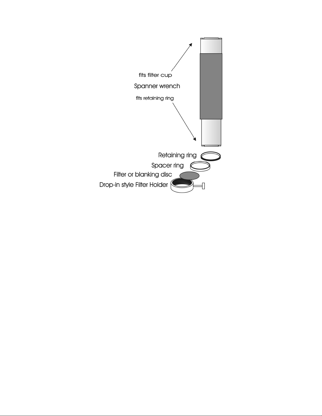
24
Figure 2-4. Filter holder components.
Retaining Ring.
Retaining Ring. This ring is threaded on its outside surface and has two slots on its top
Retaining Ring. Retaining Ring.
edge. The purpose of the two slots is for the removal and installation of the retaining ring
when using the retaining ring driver or spanner wrench that is provided with the Lambda
10-3 (shown in Figure 2-4). Note how the design of the spanner wrench differs between
25, 32, and 50 mm filter sizes.
Spacer Ring.
Spacer Ring. This ring is unthreaded and serves to evenly carry the force of the retaining
Spacer Ring.Spacer Ring.
ring to the bottom of the filter cup or holder. It is recommended that the spacer be used
anytime a blanking disc, or the filter cup or holder is installed. The spacer ring should
also be used whenever the thickness of an installed filter allows its use. Maximum filter
thicknesses for the filter cup and holders are specified in Table 2-1.
Blanking Disc.
Blanking Disc. In all but one of the filter cups (and one of the filter holders) there will
Blanking Disc. Blanking Disc.
also be a blanking disc. These are meant to prevent transmission of the high intensity
light to the microscope through unused filter positions. This is primarily a safety feature
that reduces the probability that the operator will look into the optical pathway when
dangerous, high intensity, unfiltered light is present and magnified. A blanking disc in a
filter cup can also function as a shutter in an experimental protocol.
LAMBDA 10-3 OPERATION MANUAL – REV. 3.03 (20110829)
Page 37

25
Table 2-1. Maximum allowable filter thickness.
With Spacer
(Millimeters) (Inches) (Millimeters) (Inches)
Slide
Slide----In Holder
In Holder
SlideSlide
In HolderIn Holder
Drop
Drop----In Holder
In Holder 2.2 0.086 5.38 0.212
DropDrop
In HolderIn Holder
Filter Cup
Filter Cup 5.89 0.2315 9.07 0.3575
Filter CupFilter Cup
With Spacer Without Spacer
With SpacerWith Spacer
1.38
0.054 4.56 0.18
Without Spacer
Without SpacerWithout Spacer
2.5.3
2.5.3 Installation of Filters into Filter Holders
Installation of Filters into Filter Holders
2.5.32.5.3
Installation of Filters into Filter HoldersInstallation of Filters into Filter Holders
Installation of filters into the filter holders requires care and patience to avoid damaging the
threads as well as the filters. The following procedures describe this process and should be
practiced with a drop-in (or slide-in) filter holder before attempting to load filters into the
filter cups.
Figure 2-5. Changing filters in the Slide-In Filter Holder.
LAMBDA 10-3 OPERATION MANUAL – REV. 3.03 (20110829)
Page 38

26
Figure 2-6. Removing the retaining ring.
The threaded retaining ring has two notches cut into it, 180 degrees apart. Place the notched
end of the brass spanner wrench (Figure 2-6, right) into the notches on the retaining ring
and carefully turn it counter-clockwise to unscrew it.
Once the retaining ring is removed, the spacer (and blank, if present) should be easily
removed. You should become familiar with the assembly of this retaining system. In
particular, you should develop a feel for turning the retaining ring without pushing down on
the driver or wrench. This is important because if you forcefully push on the filter holder
while you are trying to load a filter, you run the risk of scratching the filter if the tool slips
out of place!
Figure 2-7. Assembly order of filter holder parts.
Place the desired filter into the filter holder, first. With some 1” filters extra care must be
taken to avoid getting the filters jammed at an angle.
Next, install the spacer ring into the filter holder. Unless the filter thickness precludes the
use of the spacer ring (see Figure 2-6 and Figure 2-7), always install the spacer. This helps to
LAMBDA 10-3 OPERATION MANUAL – REV. 3.03 (20110829)
Page 39

27
provide maximum separation between the filter surface and end of the tool that is used to
turn the retaining ring.
Finally, install the threaded retaining ring. DO NOT OVER TIGHTEN THE RETAINING
RING! It need only be tightened until it is firmly seated.
2.5.4
2.5.4 Installation of Filters into Filter Cups
Installation of Filters into Filter Cups
2.5.42.5.4
Installation of Filters into Filter CupsInstallation of Filters into Filter Cups
Loading filters into the filter cups on the filter wheel follows the same procedure as described
above for loading filters into filter holders. There is, however, the additional complication of
working through the filter wheel housing. To gain access to the filter cups on the wheel,
unscrew the access plug from the loading port on the motor housing (i.e., the motor side of
the filter wheel). A large coin or other suitable implement can be used to remove the plug.
Once removed, the retaining ring in the underlying filter cup is accessible through that port.
To align the filter position you wish to load with the loading port, it is easiest to use the
controller to identify and position the filter cups. To begin, connect the Filter Wheel to the
controller (see the FIRST TIME USE chapter for a brief description of the principles of
operation). When you first turn on the controller, the Filter Wheel will “HOME” itself,
aligning the “0” filter position with the Optical Port and filter position #5 with the Loading
Port. The filter currently in the Loading Port is five positions removed from the one
indicated by the controller display (i.e., the one at the OPTICAL PORT). This relationship
between the filter position indicated by the controller and the filter position at the
LOADING PORT is illustrated in Figure 2-8.
LAMBDA 10-3 OPERATION MANUAL – REV. 3.03 (20110829)
Page 40

28
Filter position at optical port 0 1 2 3 4 5 6 7 8 9
Filter position at loading port 5 6 7 8 9 0 1 2 3 4
Figure 2-8. Filter ports (plug is removed from the loading port).
After identifying and positioning the filter cup to be loaded, it is advisable to turn off the
controller before removing the retaining ring from the filter cup. Follow the procedures
described above for installation of filters into filter holders.
CAUTION: An extra word of caution about excessive force is warranted at this point. DO
CAUTION: An extra word of caution about excessive force is warranted at this point. DO
CAUTION: An extra word of caution about excessive force is warranted at this point. DO CAUTION: An extra word of caution about excessive force is warranted at this point. DO
NOT APPLY EXCESSIVE FORCE! Not only do you run the ris
NOT APPLY EXCESSIVE FORCE! Not only do you run the risk of damaging the filter
NOT APPLY EXCESSIVE FORCE! Not only do you run the risNOT APPLY EXCESSIVE FORCE! Not only do you run the ris
but also the filter wheel itself can be permanently distorted by pushing too hard against
but also the filter wheel itself can be permanently distorted by pushing too hard against
but also the filter wheel itself can be permanently distorted by pushing too hard against but also the filter wheel itself can be permanently distorted by pushing too hard against
the retaining ring with the driver or wrench. If you experience problems securing the
the retaining ring with the driver or wrench. If you experience problems securing the
the retaining ring with the driver or wrench. If you experience problems securing the the retaining ring with the driver or wrench. If you experience problems securing the
retaining ring, back the ring off the filter cup and tr
retaining ring, back the ring off the filter cup and try again.
retaining ring, back the ring off the filter cup and trretaining ring, back the ring off the filter cup and tr
y again.
y again.y again.
k of damaging the filter
k of damaging the filter k of damaging the filter
After loading the filter(s), check each newly loaded filter position to make sure that the
retaining ring is not projecting above the top edge of the filter cup then replace the loading
port plug.
Another potential complication of loading filters into the filter cups can occur if the retaining
ring has been previously over-tightened. In this case, it is possible that the filter cup itself
will begin to unscrew from the wheel as the retaining ring is turned. If this occurs, STOP!
LAMBDA 10-3 OPERATION MANUAL – REV. 3.03 (20110829)
Page 41

29
Turn the spanner wrench so that the widest end is toward the filter cup and slip the wrench
into the two notches in the edge of the cup. Then turn the wrench clockwise to screw the cup
back into the slider. DO NOT push on the cup. Just screw it in until it seats firmly. It should
then be possible to remove the retaining ring as described above without the cup turning.
It may appear that removal of the cover plate from the housing would facilitate loading
filters. This is not the case! Removal of the cover plate will not give you access to the filter
cup side of the wheel and may lead to misalignment of and damage to the Filter Wheel.
Under no conditions should you ever remove the cover plate or the filter wheel from t
Under no conditions should you ever remove the cover plate or the filter wheel from the
Under no conditions should you ever remove the cover plate or the filter wheel from tUnder no conditions should you ever remove the cover plate or the filter wheel from t
motor shaft
motor shaft. Removal of the cover plate or the wheel from the shaft will void your warranty.
motor shaftmotor shaft
2.6
2.6 Filter Loading Tips
Filter Loading Tips
2.62.6
Filter Loading TipsFilter Loading Tips
2.6.1
2.6.1 Selection of a Filter Position
Selection of a Filter Position
2.6.12.6.1
Selection of a Filter PositionSelection of a Filter Position
In most cases any given filter could be installed at any of the ten FILTER POSITIONS.
However, some minor considerations may improve performance of the system. Adjacent
FILTER POSITIONS will require less switching time. Therefore, if an experiment will
require rapid switching between two filters they should be located next to one another. If
separation by one or more occupied filter positions is necessary, keep in mind that there will
be brief transitions through, possibly, undesirable wavelengths as light transmits through
those intervening filter(s) unless a shutter is installed and programmed for use.
he
he he
2.6.2
2.6.2 Use of Blanking Discs
Use of Blanking Discs
2.6.22.6.2
Use of Blanking DiscsUse of Blanking Discs
The blanking discs should only be removed from those positions that will contain a filter. The
discs are intended as a safety device to reduce the risk of the user sustaining serious and
permanent eye damage from looking in the microscope when dangerous high intensity light
is present. We strongly urge that the discs be used. Please be careful and avoid the possibility
of direct visualization of high intensity light.
2.6.3
2.6.3 Neutral Density Filt
Neutral Density Filters
2.6.32.6.3
Neutral Density FiltNeutral Density Filt
The individual filter holders are typically used for neutral density filters and are installed as
described above.
2.7
2.7 Shutter Options
Shutter Options
2.72.7
Shutter OptionsShutter Options
The Lambda 10-3 can drive two wheel-mounted shutters. That shutter can be either a Sutter
Instrument SmartShutter or a Uniblitz shutter. In either case, the wheel can be either a oneinch or a 32 mm wheel. A wheel with a smart shutter installed will attach to the DB-25
connector on the back of the controller. A wheel with a Uniblitz shutter attached will connect
via the DB-15 connector on the rear of the controller.
CAUTION: Do not attempt to connect more than one shutter or one wheel. Do not try to
CAUTION: Do not attempt to connect more than one shutter or one wheel. Do not try to
CAUTION: Do not attempt to connect more than one shutter or one wheel. Do not try to CAUTION: Do not attempt to connect more than one shutter or one wheel. Do not try to
use both the DB
use both the DB----25 and the DB
use both the DBuse both the DB
standalone
standalone filter wheel (no integrated shutter) and a standalone
standalonestandalone
which is not integrated with a filter wheel). If you do not have a shutter, use the
which is not integrated with a filter wheel). If you do not have a shutter, use the
which is not integrated with a filter wheel). If you do not have a shutter, use the which is not integrated with a filter wheel). If you do not have a shutter, use the
connector that matches the type on the wheel.
connector that matches the type on the wheel.
connector that matches the type on the wheel. connector that matches the type on the wheel.
filter wheel (no integrated shutter) and a standalone
filter wheel (no integrated shutter) and a standalone filter wheel (no integrated shutter) and a standalone
ers
ersers
25 and the DB----15 connector at the same time, except when connecting a
25 and the DB25 and the DB
15 connector at the same time, except when connecting a
15 connector at the same time, except when connecting a 15 connector at the same time, except when connecting a
SmartShutter
SmartShutter
SmartShutterSmartShutter
(one
(one
(one (one
LAMBDA 10-3 OPERATION MANUAL – REV. 3.03 (20110829)
Page 42

30
The controller will detect the SmartShutter, if installed. The controller will assume that
there is a Uniblitz shutter if no SmartShutter is detected. If you have a Uniblitz shutter, an
internal jumper, J21, on the Lambda 10-3 circuit board must be set to the correct position in
order to ensure the best performance. This jumper is used to select operation of a Uniblitz 25
mm shutter or a Uniblitz 35 mm shutter. If you have no Uniblitz shutter than the jumper
position is not significant. Position A is for 25 mm shutters and position B is for 32 mm
shutters. You can check to see which position was selected by looking through the grill on the
left side of the cabinet. If the jumper has been completely removed, 25 mm operation will also
be obtained.
2.8
2.8 Mounting a
Mounting a SmartShutter
2.82.8
Mounting a Mounting a
SmartShutter in a Lambda LS
SmartShutterSmartShutter
in a Lambda LS
in a Lambda LS in a Lambda LS
The one-inch stand-alone version of the SmartShutter can be mounted inside current
versions of the Lambda LS. A male-to-male c-mount adapter is used to couple the
SmartShutter to the c-mount block inside the Lambda LS. Stacking c-mount extension tubes
are threaded into the other side of the SmartShutter to provide an enclosed light path from
the SmartShutter to light port on the Lambda LS.
The stacking c-mount extensions that have been used in the past add 1 inch of length beyond
the male threads. These pieces are stepped down in outside diameter so that they can slip
inside a dovetail tube just as the lens tube does. The overall length of these tubes will be
reduced by 0.070 inches so that two tubes stacked will fit between the SmartShutter and the
external wall of the Lambda LS. These pieces will still be usable in conjunction with the
dovetail tube to enclose the light path when no shutter or a Vincent shutter is installed.
Until new parts are available, a single tube cut down by 0.14 inches can be stacked with a 1inch tube.
Since the Lambda LS does not have any inherent capability of controlling the SmartShutter,
an externally positioned Lambda 10-3 (or another Lambda model capable of controlling a
SmartShutter) can be used to control the SmartShutter. Additionally, the Lambda 10-3 can
be used to control one or two filter wheels, one of which may be installed inside the Lambda
LS, and another, which may be installed on the external part of the Lambda LS cabinet.
LAMBDA 10-3 OPERATION MANUAL – REV. 3.03 (20110829)
Page 43

31
3.
3. O PERA TION S
OPERA TIO NS
3.3.
OPERA TIO NSOPERA TIO NS
3.1
3.1 First Time Use
First Time Use
3.13.1
First Time UseFirst Time Use
3.1.1
3.1.1 Line Power (Mains)
Line Power (Mains)
3.1.13.1.1
Line Power (Mains)Line Power (Mains)
The power cord provided with the Lambda 10-3 connects to the Power Entry Module located
on the back of the unit (see diagram below). This module also includes the line fuse .
Figure 3-1. Lambda 10-3 cabinet (rear view) showing power connection and fuse.
The power switch is located on the front panel as shown in Figure 3-2.
Figure 3-2. Power switch (front panel).
The Lambda 10-3 has a “universal” power supply that runs on 110 volts or 220 volts AC, 50
or 60 Hz. You do not need to change settings or fuses to suit local conditions. Make certain
that the ON/OFF Switch located on the front panel of the Lambda 10-3 cabinet is turned
OFF. Plug the power cord provided with the Lambda 10-3 into the Line Input socket on the
Power Entry Module and then to a power source of the appropriate voltage and frequency.
You must replace the fuse with the appropriate value (see the Technical Specifications),
otherwise your protection from fire and electric shock will be compromised.
LAMBDA 10-3 OPERATION MANUAL – REV. 3.03 (20110829)
Page 44

32
Figure 3-3. Power connection.
3.2
3.2 Basic Operation
Basic Operation
3.23.2
Basic Operation Basic Operation
3.2.1
3.2.1 Initialization
Initialization
3.2.13.2.1
InitializationInitialization
At power on the Lambda 10-3 will rotate the filter wheel to filter position 0. If the wheel does
not rotate to this position as detected by a Hall-effect sensor, the display will indicate that
there is an error. Once the wheel is properly initialized to Filter 0, it will move to Filter 9 and
then back to Filter 0 to complete the power-on sequence. While in filter position 9 the
microprocessor checks the optical sensor to determine if a full 10-position wheel is installed.
If the optical switch indicates that it is not a 10-position wheel (such as a 50mm 5-position
wheel), the controller will only execute moves to the optical port for filters 0 through 4.
At power on the first display is the copyright message:
FILTER WHEEL CONTROLLER PROGRAM V1.19
COPYRIGHT SUTTER INSTRUMENT CORP 2004
After the copyright screen, the unit display should be similar to:
WHEEL: A-25MM 0 1 B-NC C-NC U
Where A, B, and C in the top line refer to the three filter wheel connectors (NC means “not
connected”), and U on the far right indicates Local/Remote Control state of the controller.
On the second line, A and B refer to the two possible shutters that can be connected. OFF
indicates shutter is either not connected or is in off mode. FAST indicates SmartShutter, and
blank indicates either a Vincent shutter or a shutter is not connected.
Once the unit has initialized, it is ready for USB or serial input. To use the keypad, press the
LOCAL key. You can then select filters using the numeric keys. The action associated with a
key generally occurs when the key is released. Menu choices will be covered in later sections.
SHUTR: A- OFF B-FAST OFF
3.3
3.3 Make It Go
Make It Go
3.33.3
Make It GoMake It Go
1. Turn on the power using the ON/OFF switch on the front panel of the Lambda 10-3
controller cabinet. The filter wheel will automatically go to the “Home” (0) filter position.
The current filter position will appear on the controller front panel display.
LAMBDA 10-3 OPERATION MANUAL – REV. 3.03 (20110829)
Page 45

33
2. The Lambda 10-3 will default to on-line at power-on or after a reset. If the unit is
connected to a USB port with properly installed software, the USB port will be selected as
the default remote control interface.
3. The Lambda 10-3 will be in the on-line mode at power on, ready for serial port or USB
port commands. However, it will need a valid remote-control command to pass control to
the correct input.
4. To operate in local mode, press the LOCAL key. You can then press any numeric key on
the keypad to manually select the corresponding filter position.
5. Press the shutter key to toggle the shutter open and closed (if installed).
Now that you have completed this FIRST TIME USE section of this manual, you should be
familiar with the basic components and the MANUAL operation of the Lambda 10-3. To get
set up for an experimental application you will need to:
Install
Install the desired filters into the FILTER WHEEL.
Install Install
Install the filter wheel into the optical pathway using the appropriate adapter.
Install the filter wheel into the optical pathway using the appropriate adapter.
Install the filter wheel into the optical pathway using the appropriate adapter.Install the filter wheel into the optical pathway using the appropriate adapter.
Establish the desired INTERFACE between the Lambda 10
Establish the desired INTERFACE between the Lambda 10----3 and your computer.
Establish the desired INTERFACE between the Lambda 10Establish the desired INTERFACE between the Lambda 10
the desired filters into the FILTER WHEEL.
the desired filters into the FILTER WHEEL.the desired filters into the FILTER WHEEL.
3 and your computer.
3 and your computer.3 and your computer.
Each of these steps is discussed in the following sections of the manual.
LAMBDA 10-3 OPERATION MANUAL – REV. 3.03 (20110829)
Page 46

34
(This page intentionally blank.)
LAMBDA 10-3 OPERATION MANUAL – REV. 3.03 (20110829)
Page 47

35
4.
4. O PERA TION S: M A NUA L CON TROL
OPERA TIO NS: MANUA L CON TRO L
4.4.
OPERA TIO NS: MANUA L CON TRO LOPERA TIO NS: MANUA L CON TRO L
4.1
4.1 Power
Power ----Up Sequence
4.14.1
Power Power
The control electronics for the filter changer are activated by the POWER switch (MAINS)
on the back panel of the unit. Remember, when using an arc lamp with this system it is best
to turn the lamp power supply on BEFORE turning on the Lambda 10-3. Arc lamp power
supplies produce a high voltage lamp starting pulse that may interrupt normal operation of
microprocessor-controlled devices or damage electronics.
Up Sequence
Up SequenceUp Sequence
When power is applied, the LAMBDA 10
determine the mechanical equipment attached to the controller. As part of this process, the
filter wheel will rotate at a slow rate until sensors in the mechanical units signal that the “0”
filter position is lined up with the optical port. The wheel will then make an additional move
away from filter 0 and then back to filter 0. The controller currently automatically recognizes
3 different classes of filter wheels: standard 10-position, high-speed 4-position, and highcurrent 10 -position (32 mm). At power on, the Lambda 10-3 will rotate the filter wheel to
filter position 0. If the wheel does not rotate to this position as detected by a Hall effect
sensor, the display will indicate that there is an error. If the microprocessor detects that it is
not a 10-position wheel, the controller will only execute moves to filter positions 0 through 3.
While the unit is going through these steps, the following screen is displayed:
LAMBDA 10----3333 performs several initial tests in order to
LAMBDA 10LAMBDA 10
FILTER WHEEL CONTROLLER PROGRAM V1.21
After the copyright screen, the status screen is displayed:
COPYRIGHT SUTTER INSTRUMENT CORP 2004
WHEEL: A-25MM 0 1 B-NC C-NC U
SHUTR: A- OFF B-FAST OFF
Once the unit has initialized, it is ready for USB input, as indicated by the U at the right side
of the first display line. Serial input can be activated as noted in the section on the serial port
(in which case, the U is replaced with an S.). To use the keypad, press the LOCAL key. When
LOCAL is pressed, the last character on the first line will change to an L
NOTE: In Lambda 10
NOTE: In Lambda 10----3’s programmed with Firmware Rev. 1.21, the parallel port has been
NOTE: In Lambda 10NOTE: In Lambda 10
added as a third choice for remote control. Additionally, the capability of selecting which
added as a third choice for remote control. Additionally, the capability of selecting which
added as a third choice for remote control. Additionally, the capability of selecting which added as a third choice for remote control. Additionally, the capability of selecting which
remote control interface is the power
remote control interface is the power----on default (“
remote control interface is the powerremote control interface is the power
for Parallel) has been added.
for Parallel) has been added.
for Parallel) has been added.for Parallel) has been added.
WHEEL: A-25MM 0 1 B-NC C-NC L
SHUTR: A- OFF B-FAST OFF
3’s programmed with Firmware Rev. 1.21, the parallel port has been
3’s programmed with Firmware Rev. 1.21, the parallel port has been 3’s programmed with Firmware Rev. 1.21, the parallel port has been
on default (“U” for USB, “S” for serial RS
on default (“on default (“
LAMBDA 10-3 OPERATION MANUAL – REV. 3.03 (20110829)
U” for USB, “S” for serial RS----232, or “P”
U” for USB, “S” for serial RSU” for USB, “S” for serial RS
232, or “P”
232, or “P” 232, or “P”
Page 48

36
(Mode menu prior to Lambda 10
-
3 Firmware Rev. 1.21.)
(Mode menu in Lambda 10
-
3 Firmware Rev. 1.21 and higher.)
4.2
4.2 Setting the Position of the Active Filter Wheel
Setting the Position of the Active Filter Wheel
4.24.2
Setting the Position of the Active Filter WheelSetting the Position of the Active Filter Wheel
Pressing the corresponding numeric key when the controller is in the local mode chooses a
filter position on the wheel. Keys are read while depressed but the appropriate action will
occur only when the key is released. If a key is pressed while a move is in progress but
released after the move is over, the key will read normally. Keys pressed and released while a
move is in progress are ignored. The filter position currently located in the optical port will
be indicated on the display (see example above).
4.3
4.3 Toggling Shutter States (S1 and S2)
Toggling Shutter States (S1 and S2)
4.34.3
Toggling Shutter States (S1 and S2)Toggling Shutter States (S1 and S2)
Press the S1
Shutter A. S2
4.4
4.4 Disp
4.44.4
In order to access the main menu in the local mode, press MODE. There will be a brief
display of the message:
The menu screen, shown below, then quickly replaces the momentary screen shown
previously:
4.5
4.5 Selecting Various Modes and Configurations with the MODE Key
4.54.5
Pressing the MODE key while the Status screen is displayed, causes the following screen to
be displayed.
S1 key on the 10-3 controller keypad to manually toggle the open/closed state of
S1 S1
S2 performs the same operation on Shutter B.
S2S2
Displaying the Main Menu
laying the Main Menu
DispDisp
laying the Main Menulaying the Main Menu
PRESS KEY 0 TO EXIT THE MENU ANYTIME!!!
Selecting Various Modes and Configurations with the MODE Key
Selecting Various Modes and Configurations with the MODE KeySelecting Various Modes and Configurations with the MODE Key
1-WHEEL 2-SPEED 3-SHUTTER TTL 4-TEST
SMART SHUTTER ONLY: 5-MODE 6-CONFIG
The menu shown provides for making the following settings:
1. Set active filter wheel for manual filter position control
2. Set the speed for the active filter wheel
3. Establish shutter TTL control
4. Enter test/demo mode
5. Select shutter mode (SmartShutter only)
1-ACTIVE WHEEL 2-SPEED 3-TTL 4-TEST
5-SHUTTER MODE 6-CONFIG 7-DEFAULT
LAMBDA 10-3 OPERATION MANUAL – REV. 3.03 (20110829)
Page 49

37
6. Save and load configurations
7. Set power-up default settings (in Lambda 10-3 Firmware Rev. 1.21 and later)
4.6
4.6 Selecting the Active Filter Wheel for Manual Control (MODE 1)
Selecting the Active Filter Wheel for Manual Control (MODE 1)
4.64.6
Selecting the Active Filter Wheel for Manual Control (MODE 1)Selecting the Active Filter Wheel for Manual Control (MODE 1)
When pressing keys 1 through 0 on the keypad while in Local mode, the currently active
filter wheel moves to the corresponding filter position. By default, when the Lambda 10-3 is
first powered on, Wheel A is the active filter wheel. The active filter wheel can be changed by
pressing MODE, then 1, followed by 1 for Wheel A, 2 for Wheel B, or 3 for Wheel C.
4.7
4.7 Selecting the Speed for the Active Filter Wheel (MODE 2)
Selecting the Speed for the Active Filter Wheel (MODE 2)
4.74.7
Selecting the Speed for the Active Filter Wheel (MODE 2)Selecting the Speed for the Active Filter Wheel (MODE 2)
The speed of the currently active filter wheel is set by, while at the Status screen, pressing
MODE, pressing 2, followed by one of eight speeds (keys 0 through 7). The following screen is
displayed after pressing MODE 2 from the Status screen or pressing 2 from MODE screen.
Speed 0 is the fastest speed and 7 is the slowest. Entering the selected speed under computer
control is covered in a separate section.
The switching times (in milliseconds) for each of the 8 speeds is given in Table 4-1. Note that
a 5-filter position move is the longest move on the 10-position filter wheel, since the
controller will always rotate the correct direction to make the fastest change of position. For
a given speed, the time for a move to a non-adjacent filter will take about 1.8, 2.5, 3.3 or 4
times as long as a move to an adjacent filter, depending on the number of filters to be
skipped. The highest speed that can be used will depend on the weight of the filters mounted
in the wheel. In a 25mm, 10-position filter wheel equipped with two typical filters and eight
blocking disks, adjacent filters can be changed in less than 40 milliseconds with a speed
setting of 1. A correspondingly-equipped 32mm wheel may require a lower speed.
SELECT ACTIVE WHEEL(MUST BE CONNECTED):
1-WHEEL A 2-WHEEL B 3-WHEEL C
PLEASE ENTER THE NEW SPEED VALUE BETWEEN
0-7 .....
LAMBDA 10-3 OPERATION MANUAL – REV. 3.03 (20110829)
Page 50

38
Table 4-1. Filter switching times (in milliseconds).
Number of Filter Positions Moved
Speed Setting
Speed Setting 1111 2222 3333 4444 5555
Speed SettingSpeed Setting
0*
0* 31 51 74 95 115
0*0*
1111 40 65 95 120 148
2222 44 75 105 136 168
3333 50 88 127 165 205
4444 60 108 156 205 250
5555 68 123 178 235 290
6666 124 235 350 460 580
7777 230 440 650 860 1100
* NOTE:
NOTE: Speed 0 should be used only with 4-position filter wheels
NOTE:NOTE:
Number of Filter Positions Moved
Number of Filter Positions MovedNumber of Filter Positions Moved
(LB10-WHS4, LB10-WHS4IQ, or LB10-WHS4E).
4.8
4.8 Selecting Shutter TTL Control (MODE 3)
Selecting Shutter TTL Control (MODE 3)
4.84.8
Selecting Shutter TTL Control (MODE 3)Selecting Shutter TTL Control (MODE 3)
The way in which shutters can be controlled via the TTL input port is determined by
pressing MODE and then 3, whereupon the following menu is displayed.
4.8.1
4.8.1 Enabling Shutter TTL Control (MODE 3 1 or MODE 3 3)
Enabling Shutter TTL Control (MODE 3 1 or MODE 3 3)
4.8.14.8.1
Enabling Shutter TTL Control (MODE 3 1 or MODE 3 3)Enabling Shutter TTL Control (MODE 3 1 or MODE 3 3)
The TTL input port for Shutter A is enabled by pressing 1 and is disabled by pressing 2. The
TTL input port for Shutter B is enabled by pressing 3 and is disabled by pressing 4.
SHUTTER A: 1-ENABLE TTL 2-DISABLE TTL
SHUTTER B: 3-ENABLE TTL 4-DISABLE TTL
4.8.2
4.8.2 Determining the Shutter TTL Control Mode (MODE 3 1 1|2|3 or MODE 3 3 1|2|3)
Determining the Shutter TTL Control Mode (MODE 3 1 1|2|3 or MODE 3 3 1|2|3)
4.8.24.8.2
Determining the Shutter TTL Control Mode (MODE 3 1 1|2|3 or MODE 3 3 1|2|3)Determining the Shutter TTL Control Mode (MODE 3 1 1|2|3 or MODE 3 3 1|2|3)
Once TTL control for a shutter is enabled, the following menu is displayed which lists the
choices for the mode in which the TTL input for the shutter is to operate.
SHUTTER OPEN ON: 1-HIGH 2-LOW
SHUTTER TOGGLE ON: 3-RISING EDGE
Press 1 to configure TTL control of the shutter to open the shutter when a high signal is
applied to the shutter’s TTL input port. To have the shutter open when the TTL input goes
low, press 2
For toggle control of the shutter during the rising edge of a high signal on the TTL port,
press 3. Toggle means the shutter opens if it is closed, and closes if it is open.
LAMBDA 10-3 OPERATION MANUAL – REV. 3.03 (20110829)
Page 51

39
4.9
4.9 Selecting a Test Mode (MODE 4)
Selecting a Test Mode (MODE 4)
4.94.9
Selecting a Test Mode (MODE 4)Selecting a Test Mode (MODE 4)
Up to four test/demo modes can be selected from the menu that is displayed when MODE
and 4 are pressed.
1111----LOOP
LOOP is a test of serial communications
LOOPLOOP
2222----SPEED
SPEED is a utility that helps select the correct operational speed to select.
SPEEDSPEED
3333----DEMO
DEMO is a demo of the wheel and shutter
DEMODEMO
4444----SMART SHUTTER
SMART SHUTTER is a demo of the shutter operation
SMART SHUTTERSMART SHUTTER
4.10
4.10 Selecting SmartShutter Modes (MODE 5)
Selecting SmartShutter Modes (MODE 5)
4.104.10
Selecting SmartShutter Modes (MODE 5)Selecting SmartShutter Modes (MODE 5)
Opening and closing the SmartShutter involves separate commands. The mode selection in
this menu controls the way in which the SmartShutter opens and closes.
FAST
FAST ---- In this mode the SmartShutter opens and closes as quickly as possible, which is about
FAST FAST
8 msec.
PLEASE CHOOSE THE TEST MODE:
1-LOOP 2-SPEED 3-DEMO 4-SMART SHUTTER
SHUTTER A MODE: 1-FAST 2-SOFT 3-ND
SHUTTER B MODE: 4-FAST 5-SOFT 6-ND
SOFT
SOFT ---- In this mode the shutter motion is slowed considerably in order to reduce the chance
SOFT SOFT
of producing vibration
ND
ND ---- In this mode, the extent of opening is determined by additional numeric key presses
ND ND
with a value of 1
store the result. 1 produces so little movement that the shutter blade should still block the
aperture, whereas 144 produces full opening. Owing to the geometry of the blade and the
aperture, the amount of attenuation will not be a linear function of the value entered. In
addition, partial opening may cause shading if the SmartShutter is not used in an
appropriate optical system.
4.10.1
4.10.1 Setting a SmartShutter to Neutral Density Mode
4.10.14.10.1
When pressing 3 or 6 for “ND” (Neutral Density), the following screen displays which
requests the entry of the number of microsteps the SmartShutter’s motor should travel in
order to achieve the desired partial opening.
Enter a value from 1 to 144 for the neutral density setting. Once entered, the main status
menu will now show the selected neutral density setting for the selected SmartShutter.
Setting a SmartShutter to Neutral Density Mode
Setting a SmartShutter to Neutral Density ModeSetting a SmartShutter to Neutral Density Mode
1 to 144
1 1
....
144. When you have keyed in the desired value, press the ENTER
144 144
ENTER key to
ENTERENTER
ENTER THE STEPS BETWEEN 1 - 144
ND SHUTTER STEPS:
LAMBDA 10-3 OPERATION MANUAL – REV. 3.03 (20110829)
Page 52

40
4.11
4.11 Saving and
Saving and Restoring SmartShutter Mode Configurations (MODE 6)
4.114.11
Saving andSaving and
Restoring SmartShutter Mode Configurations (MODE 6)
Restoring SmartShutter Mode Configurations (MODE 6) Restoring SmartShutter Mode Configurations (MODE 6)
4.12
4.12 New Menus as of Lambda 10
New Menus as of Lambda 10----3 Firmware Rev. 1.21
4.124.12
New Menus as of Lambda 10New Menus as of Lambda 10
4.12.1
4.12.1 Setting Power
4.12.14.12.1
In Lambda 10-3’s programmed with firmware Rev. 1.21 or later, a new command was added
to the main menu called “7 – Defaults”. By pressing MODE and then 7, the following menu is
displayed.
1-Set the new default
Setting Power----up Defaults (MODE 7)
Setting PowerSetting Power
WHEEL: A-25MM 0 1 B-NC C-NC U
SHUTR: A-N(5/144) OFF B- OFF
SAVE INFO AS: 1-CFG1 2-CFG2 3-CFG3
GET INFO FROM: 4-CFG1 5-CFG2 6-CFG3
3 Firmware Rev. 1.21
3 Firmware Rev. 1.213 Firmware Rev. 1.21
1-ACTIVE WHEEL 2-SPEED 3-TTL 4-TEST
5-SHUTTER MODE 6-CONFIG 7-DEFAULT
up Defaults (MODE 7)
up Defaults (MODE 7)up Defaults (MODE 7)
2-Reset all to factory default
1-SET THE NEW DEFAULT
2-RESET ALL TO FACTORY DEFAULT
SPEED: 1-WA 2-WB 3-WC 4-COMM_PORT
Speed: 1-WA 2-WB 3-WC 4-Comm_Port
Filter: 5-WA 6-WB 7-WC 8-Shutter_Mode
Setting More Power up Defaults
FILTER: 5-WA 6-WB 7-WC 8-SHUTTER_MODE
DO YOU WANT TO SET OTHER DEFAULT VALUES?
4.12.1.1 Setting the Speed Defaults for Wheels A, B, & C (MODE 7 1 1|2|3 [0 – 7])
Please enter the new default speed value between 0-7 …..
1-YES 0-NO
PLEASE ENTER THE NEW DEFAULT SPEED VALUE
BETWEEN 0-7 ......
LAMBDA 10-3 OPERATION MANUAL – REV. 3.03 (20110829)
Page 53

41
4.12.1.2 Setting the Position (Filter) Defaults for Wheels A, B, & C (MODE 7 1 5|6|7 [0 – 7])
Please enter the default filter value between 0-9……
PLEASE ENTER THE NEW DEFAULT FILTER
4.12.1.3 Setting the Default Communications Port (MODE 7 1 4)
MODE 7 1 4 (comm. port)
Please select the default comm. port: 1-USB 2-Serial 3-Parallel
(USB = MODE 7 1 4 1)
(Serial = MODE 7 1 4 2)
(Parallel = MODE 7 1 4 3)
VALUE BETWEEN 0-9......
PLEASE SELECT THE DEFAULT COMMUNICATION
4.12.1.4 Setting the Current SmartShutter Mode as the Default (MODE 7 1 8 1|2)
MODE 7 1 8 (shutter mode)
PORT: 1-USB 2-SERIAL 3-PARALLEL
ARE YOU SURE TO RESET ALL THE SETTINGS
TO THE FACTORY DEFAULT? 1-YES 0-NO
4.12.1.5 Resetting All to Factory Defaults (MODE 7 2)
When selecting “reset all to factory defaults” , the following menu is displayed, providing you
a choice of going ahead with the reset or canceling.
ARE YOU SURE TO RESET ALL THE SETTINGS
If pressing 0 (for “No”) to cancel resetting all to the factory defaults, the command is
cancelled and the display returns immediately to the main status menu.
If 1 (for “Yes”) is pressed, the controller immediately sets all settings to their factory defaults
(listed below), and the display returns immediately to the main status menu.
The factory defaults are:
TO THE FACTORY DEFAULT? 1-YES 0-NO
LAMBDA 10-3 OPERATION MANUAL – REV. 3.03 (20110829)
Page 54

42
Table 4-2. Factory defaults for filter wheels, SmartShutters, and communications ports.
Device
Device Setting
DeviceDevice
Setting
SettingSetting
A
Position (Filter) 0
Speed 1
Filter Wheels
B
Position (Filter) 0
Speed 1
C
Position (Filter) 0
Speed 1
A Mode Fast
SmartShutters
B Mode Fast
C Mode Fast
Remote Control Communications Port “U” (USB)
Wheel Position: A, B, C: Position (Filter) 0
Wheel Speed: A, B, C: Speed 1.
Comm. Port: USB, Serial, Parallel: USB.
Shutter (A, B, &C) Mode: Fast, Soft, Neutral Density (1 – 144): Fast.
LAMBDA 10-3 OPERATION MANUAL – REV. 3.03 (20110829)
Page 55

43
5.
5. E XTE RNAL
EXTE RNAL CO MMAN D
5.5.
EXTE RNAL E XTE RNAL
COMMA ND CONT ROL O PERA TION S
COMMA ND C OMMA ND
CONT ROL O PERA TION S OV ERVI EW
CONT ROL O PERA TION SCONT ROL O PERA TION S
OVER VIEW
OVER VIEW OV ERVI EW
The remote control of the Lambda 10-3 can be achieved by issuing commands on a remote
computer and transmitting them to the Lambda 10-3 over a serial
serial (RS-232) or USB
serialserial
USB
USBUSB
(Universal Serial Bus) connection. In versions of the Lambda 10-3 programmed with version
1.21 or later of the firmware, remote control can also be achieved via a parallel connection.
This chapter provides a description of these commands and how they are used. Limited
remote control can also be achieved with a TTL connection, a description for which is
provided later in this manual.
The following table shows how remote commands are categorized.
Table 5-1. Remote control command categories.
Category
Category Description
CategoryCategory
Description
DescriptionDescription
Filter commands
Shutter commands
Special commands
These are commands used exclusively for controlling
filter wheels.
These are commands used exclusively for controlling
shutters (SmartShutters and/or Vincent shutters).
These are commands for the general control of the
Lambda 10-3 controller, and are not specifically related to
either filter wheels or shutters.
Most of the commands described in this chapter are ones that are sent from the computer to
the Lambda 10-3. Some of these commands will cause the Lambda 10-3 to return certain
special codes or one or more bytes of data. Some commands must be followed by one or more
bytes containing parameters. For each byte sent to the Lambda 10-3, that same byte is
echoed (transmitted) back to the remote computer as confirmation that the byte was
received. The echoing back of command bytes in no way indicates validation of a command or
parameter, but is rather an acknowledgement from the controller that the byte was received.
When the Lambda 10-3 controller finishes performing the task associated with a command
(or command followed by one or more parameter bytes), an ASCII carriage return (CR, 13
decimal, or 0D hexadecimal) is transmitted back to the host computer as an indication that
function associated with the command has completed and that the controller is now ready for
another command. This echoing back of bytes sent by the remote computer to the controller,
and the return of an ASCII carriage return after a command’s task is complete is the same
for the serial, USB, and parallel interfaces.
5.1
5.1 Input Command Structure
Input Command Structure
5.15.1
Input Command StructureInput Command Structure
5.1.1
5.1.1 Command De
Command Descriptions
5.1.15.1.1
Command DeCommand De
scriptions
scriptionsscriptions
The following table provides a complete list of all the remote commands for the Lambda 10-3.
LAMBDA 10-3 OPERATION MANUAL – REV. 3.03 (20110829)
Page 56

44
Table 5-2. Remote Control Commands.
Command
Command Value
CommandCommand
Set filte
Set filter wheel,
Set filteSet filte
speed and position
speed and position
speed and positionspeed and position
r wheel,
r wheel, r wheel,
(See Table 5-3 for
possible value ranges
Value
ValueValue
(Decimal,
(Decimal,
(Decimal, (Decimal,
hexadecimal, &
hexadecimal, &
hexadecimal, & hexadecimal, &
binary)
binary)
binary)binary)
and Table 5-4. for the
filter command
structure.)
Open Shutter A
Open Shutter A 170
Open Shutter AOpen Shutter A
AA
10101010
Open Shutter A
Open Shutter A
Open Shutter A Open Shutter A
Conditional
Conditional
ConditionalConditional
171
AB
10101011
Close Shutter A
Close Shutter A 172
Close Shutter AClose Shutter A
AC
10101100
Open Shutter B
Open Shutter B 186
Open Shutter BOpen Shutter B
BA
10111010
Open Shutter B
Open Shutter B
Open Shutter B Open Shutter B
Conditional
Conditional
ConditionalConditional
187
BB
10111011
Close Shutter B
Close Shutter B 188
Close Shutter BClose Shutter B
BC
10111100
Batch Start
Batch Start 189
Batch StartBatch Start
BD
10111101
Batch End
Batch End 190
Batch EndBatch End
BE
10111110
Description
Description
DescriptionDescription
Sets the filter wheel (A, B, or C), the filter wheel
speed (0 – 7), and the filter position (0 – 9). Bit 7 is
set to 0 for Wheel A or C, and 1 for Wheel B. For
Wheel C, a byte containing a value of 252 decimal (FC
hexadecimal) must precede the command byte. The
filter wheel speed is encoded in octal (base 8) using
Bits 6, 5, & 4. The filter position is encoded in BCD
(Binary Coded Decimal) using the least significant
nibble (Bits 3, 2, 1, & 0).
Sets the state of Shutter A to open.
Configures Shutter A to open while the filter wheel is
stopped. The shutter will close each time the filter
wheel moves and then will open again at the end of
the move.
Sets the state of Shutter A closed.
Sets the state of Shutter B to open.
Configures Shutter B to open while the filter wheel is
stopped. The shutter will close each time the filter
wheel moves and then will open again at the end of
the move.
Sets the state of Shutter B closed.
Instructs the controller to collect the next 1 to 6 bytes
representing filter wheel and shutter
movement/action commands, until the Batch End
command is received, whereupon the collected filter
wheel and shutter commands are executed in quick
succession.
NOTE: This command supports filter wheels A, B,
and C, and shutters A and B – it should not be
confused with the Batch Transfer command, which
does not support Wheel C.
Instructs the controller that the Batch Start
command and the one to six wheel/shutter
movement/action command sequence has ended -- the
collected filter wheel and shutter commands are
LAMBDA 10-3 OPERATION MANUAL – REV. 3.03 (20110829)
Page 57

45
Command
Command Value
CommandCommand
hexadecimal, &
hexadecimal, &
hexadecimal, & hexadecimal, &
Status
Status
StatusStatus
All Motors Power
All Motors Power
All Motors Power All Motors Power
On
On
OnOn
All Motors Power
All Motors Power
All Motors Power All Motors Power
Off
Off
OffOff
Fast
Fast----mode Shutter
mode Shutter
FastFast
mode Shuttermode Shutter
Soft
Soft----mode Shutter
mode Shutter
SoftSoft
mode Shuttermode Shutter
Neutral Density
Neutral Density----
Neutral DensityNeutral Density
mode Shutter
mode Shutter
mode Shuttermode Shutter
DE + 01 or 02 +
Batch Transfer
Batch Transfer
Batch TransferBatch Transfer
Value
ValueValue
(Decimal,
(Decimal,
(Decimal, (Decimal,
binary)
binary)
binary)binary)
204
CC
11001100
206
CE
11001110
207
CF
11001111
220 + 1 or 2
DC + 01 or 02
11011100 +
00000001 or
00000010
221 + 1 or 2
DD + 01 or 02
10111011 +
00000001 or
00000010
222 + 1 or 2 +
1 – 144
01 – 90
10111100 +
00000001 or
00000010+
00000001 -
10010000
223
DF
11011111
Description
Description
DescriptionDescription
executed in quick succession.
Returns status of unit in two bytes
Instruct the controller to power on all motors.
Instruct the controller to power off all motors.
Sets the shutter to fast mode (SmartShutter only).
Second byte indicates Shutter A (1) or B (2).
Sets the shutter to soft mode (SmartShutter only).
Second byte indicates Shutter A (1) or B (2).
Sets the shutter to neutral-density mode
(SmartShutter only). Second byte indicates Shutter A
(1) or B (2). The third byte contains a value of 1
through 144 indicating the number of microsteps.
Instructs the controller to collect the next four
wheel/shutter commands. Once received, the four
commands are executed in quick succession. This
command was introduced in the Lambda 10-2; it is
retained in the Lambda 10-3 for compatibility with
applications that already have this functionality
programmed.
NOTE: This batch command does not support Wheel
C – use the Batch Start and Batch End command
sequence instead if support for Wheel C is required.
LAMBDA 10-3 OPERATION MANUAL – REV. 3.03 (20110829)
Page 58

46
Command
Command Value
CommandCommand
(Decimal,
(Decimal,
(Decimal, (Decimal,
hexadecimal, &
hexadecimal, &
hexadecimal, & hexadecimal, &
binary)
binary)
binary)binary)
Value
ValueValue
Description
Description
DescriptionDescription
Transfer to On
Transfer to On
Transfer to On Transfer to On
Line
Line
LineLine
Transfer to Local
Transfer to Local
Transfer to LocalTransfer to Local
Reset
Reset
ResetReset
Get Controller
Get Controller
Get Controller Get Controller
Type and
Type and
Type and Type and
Configuration
Configuration
ConfigurationConfiguration
238
EE
11101110
239
EF
11101111
251
FB
11111011
253
FD
11111011
Puts controller on-line
Puts controller in local mode
Resets the controller
Queries the controller as to its type and
configuration.
Commands sent to the controller via the serial, USB, or parallel interface are structured in a
one-byte (8-bit) signal. Some commands are followed by one or more bytes containing
additional parameter information for the command. The 8 bits can be used to convey three
types of commands.
Filter Commands.
Filter Commands. These commands select the desired filter position and switching speed.
Filter Commands.Filter Commands.
The filter position and switching speed are each specified by the encoding of specific bits
within the command byte.
1. The filter position is specified in the least significant 4 bits (nibble) of the byte (Bits 3,
2, 1, and 0), providing value range of 0 through 9. Because only 10 possible filter
positions are encoded in these bits, they are effectively encoded in Binary Coded
Decimal (BCD) format, leaving the values of 10 through 15 (decimal) available for use
by Shutter and Special commands.
2. The filter switching speed is specified in the least significant 3 bits within the most
significant nibble of the byte (Bits 6, 5, & 4), providing a value range of 0 through 7.
These bits are interpreted as the filter switching speed only if the bits in the lower
nibble of the byte contain a value of 0 through 9, specifying the filter position as
described previously
3. The filter wheel selection is specified in the most significant bit of the byte (Bit 7).
This bit is set to 0 to indicate the first (Wheel A) or the third (Wheel C), and is set to 1
to indicate the second wheel (Wheel B). When the third wheel (Wheel C) is indicated,
a prefix byte is required before the filter wheel command byte, in order to indicate
that the filter wheel command byte refers to Wheel C and not Wheel A.
Shutter Commands.
Shutter Commands. These commands control the open and closed states of shutters as
Shutter Commands.Shutter Commands.
well various modes in which SmartShutters can operate.
Special Commands.
Special Commands. These commands are used to control various aspects of the controller
Special Commands.Special Commands.
that are not specifically related to either filters or shutters. Some of these commands are
also used to obtain status and configuration information of the controller.
LAMBDA 10-3 OPERATION MANUAL – REV. 3.03 (20110829)
Page 59

47
The microprocessor in the controller is programmed to distinguish between these two types
of input commands based on the bit pattern of the command and will respond accordingly.
These two types of commands are discussed in more detail in the following sections.
The following table shows the command byte value ranges for filter commands and those for
shutter/special commands.
Table 5-3. Command Code Ranges.
Filter Command Ranges
Filter Command Ranges Shutter and Special Command Ranges
Filter Command RangesFilter Command Ranges
Hexadecimal
Hexadecimal Binary
HexadecimalHexadecimal
Binary Decimal
BinaryBinary
Decimal Hexadecimal
DecimalDecimal
Shutter and Special Command Ranges
Shutter and Special Command RangesShutter and Special Command Ranges
Hexadecimal Binary
HexadecimalHexadecimal
Binary Decimal
BinaryBinary
Decimal
DecimalDecimal
00 - 09
10 – 19
20 – 29
30 – 39
40 – 49
50 – 59
60 – 69
70 – 79
80 – 89
90 – 99
A0 – A9
B0 – B9
C0 – C9
D0 – D9
E0 – E9
F0 – F9
00000000
00001001
00010000
00011001
00100000
00101001
00110000
00111001
01000000
01001001
01010000
01011001
01100000
01101001
01110000
01111001
10000000
10001001
10010000
10011001
10100000
10101001
10110000
10111001
11000000
11001001
11010000
11011001
11100000
11101001
11110000
11111001
0 - 9 0A – 0F
16 - 25 1A – 1F
32 - 41 2A – 2F
48 - 57 3A – 3F
64 - 73 4A – 4F
80 - 89 5A – 5F
96 - 105 6A – 6F
112 - 121 7A – 7F
128 - 137 8A – 8F
144 - 153 9A – 9F
160 - 169 AA – AF
176 - 185 BA – BF
192 - 201 CA – CF
208 - 217 DA – DF
224 - 233 EA – EF
240 - 249 FA – FF
00001010
00001111
00011010
00011111
00101010
00101111
00111010
00111111
01001010
01001111
01011010
01011111
01101010
01101111
01111010
01111111
10001010
10001111
10011010
10011111
10101010
10101111
10111010
10111111
11001010
11001111
11011010
11011111
11101010
11101111
11111010
11111111
10 - 15
26 - 31
41 - 47
58 - 63
74 - 79
90 - 95
106 - 111
122 - 127
138 - 143
154 - 159
170 - 175
186 - 191
202 - 207
218 - 223
234 - 239
250 - 255
5.2
5.2 Filter Wheel Commands
Filter Wheel Commands
5.25.2
Filter Wheel CommandsFilter Wheel Commands
A byte command sent to the controller that contains a value from 0 through 121 decimal (00
through 79 hexadecimal) is interpreted as a Filter Wheel Command. Within a Filter Wheel
LAMBDA 10-3 OPERATION MANUAL – REV. 3.03 (20110829)
Page 60

48
Command byte, three parameters are encoded: Filter Wheel, Speed, and Position. The
accommodation of these three parameters within a single byte is accomplished by breaking
up the byte into three parts: two bit groups, and one single bit, as follows.
WHEEL BIT:
WHEEL BIT: Bit 7 is used to select the filter wheel to which the encoded command byte
WHEEL BIT: WHEEL BIT:
applies. If Bit 7 is set to 0, either Wheel A or Wheel C is selected, and if set to 1, then
Wheel B is selected. In order have Bit 7 apply to Wheel C (when the bit is set to 0), the
entire encoded filter wheel command byte must be preceded by a byte containing the
value of 252 decimal (FC hexadecimal, or 11111100 binary).
SPEED
SPEED BIT
SPEED SPEED
BIT GROUP:
GROUP: These 3 bits select the speed of movement used in advancing to the
BIT BIT
GROUP:GROUP:
next filter. The speed group is treated as a three-place binary number whose equivalent
decimal value, 0 through 7, correspond to the selected speed.
FILTER POSITION
FILTER POSITION BIT
FILTER POSITION FILTER POSITION
BIT GROUP:
GROUP: This group consists of all four bits within the lower
BIT BIT
GROUP:GROUP:
nibble of the byte (the least significant 4 bits of the byte). These four bits select the
desired filter (i.e., the filter wheel position). This group is treated as a four-place binary
number, with the equivalent decimal values 0 through 9 corresponding to the selected
filter position. These four bits can also be thought of as containing a BCD (Binary Coded
Decimal) value, since BCD always use four bits to encode only decimal values 0 through 9.
Values 10 through 15 decimal (A through F hexadecimal) in these four bits are currently
undefined and should never occur. Binary codes with decimal values greater than 9 are
ignored, unless the binary value (in conjunction with the SPEED GROUP bits)
corresponds with the decimal equivalent of one of the Special Command Codes listed later
in this chapter.
To send a filter command
determined for the desired filter position
respectively). As mentioned above, the filter wheel
filter command via the remote-control port, the binary value must first be
filter commandfilter command
filter position (4 bits) and switching speed
filter positionfilter position
filter wheel (A, B, or C) is selected by setting Bit 7 to 0
filter wheelfilter wheel
switching speed (4 bits and 3 bits,
switching speedswitching speed
for Wheel A or C, and to 1 for Wheel B. All three sets of bits are combined into a single byte
(8 bits) in order to construct the “filter command”. All eight bits of the filter command are
then sent at once to the Lambda 10-3 controller over the chosen communication interface
(serial, USB, or parallel). The following table shows a filter command is made up of the three
sets of bits (Wheel, Speed, and Position).
Table 5-4. Filter Command Structure.
Byte Bit Positiona
Byte Bit Positional #
Byte Bit PositionaByte Bit Positiona
Functional Bit
Functional Bit
Functional Bit Functional Bit
Groups
Groups
GroupsGroups
Group Bit #
Group Bit # 0000 2222 1111 0000 3333 2222 1111 0000
Group Bit #Group Bit #
Decimal Group Values
Decimal Group Values 0-1 0-7 0-9
Decimal Group ValuesDecimal Group Values
Binary Group Values
Binary Group Values 0-1 000-111 0000-1001
Binary Group ValuesBinary Group Values
Parallel Port Pin #
Parallel Port Pin # 9 8 7 6 5 4 3 2
Parallel Port Pin #Parallel Port Pin #
l # 7777 6666 5555 4444 3333 2222 1111 0000
l #l #
Wheel
Wheel
WheelWheel
Speed
Speed Filter Position
SpeedSpeed
Filter Position
Filter PositionFilter Position
NOTE: To select Wheel C, Bit 7 is set to
NOTE: To select Wheel C, Bit 7 is set to 0 and the entire filter wheel command byte
NOTE: To select Wheel C, Bit 7 is set toNOTE: To select Wheel C, Bit 7 is set to
must be preceded by a byte containing the value of 252 decimal (FC hexadecimal).
must be preceded by a byte containing the value of 252 decimal (FC hexadecimal).
must be preceded by a byte containing the value of 252 decimal (FC hexadecimal).must be preceded by a byte containing the value of 252 decimal (FC hexadecimal).
LAMBDA 10-3 OPERATION MANUAL – REV. 3.03 (20110829)
0 and the entire filter wheel command byte
0 and the entire filter wheel command byte 0 and the entire filter wheel command byte
Page 61

49
In the previous table, “Decimal Group Values” are equivalent to the values of the desired
Filter Wheel (always 0), Switching Speed (0 through 7) and Filter Position (0 through 9).
Their hexadecimal and binary equivalents are shown as the “Hexadecimal Group Values”
and “Binary Group Values”, respectively. These 8 bits are the raw data, then, that serve as a
Filter Command to select the Filter Position and Switching Speed via the Lambda 10-3
controller’s serial and USB ports. The Wheel bit (Bit 7) is used to select the filter wheel: 0 for
Wheel A or C, and 1 for Wheel B. When selecting Wheel C, the encoded filter wheel command
byte must be preceded by a byte containing the value of 252 decimal (FC hexadecimal), and
Bit 7 in the encoded wheel command byte must be set to 0. In summary, the controller will
treat any byte it receives from the remote computer as a “filter command” if the byte’s least
significant nibble contains a value of 0 through 9. If the received byte’s least significant
nibble contains a decimal value of 10 through 15, then the controller treats the entire byte as
a “special command” or “shutter command”.
5.2.1
5.2.1 Filter Wheel Comm
Filter Wheel Command Byte Encoding
5.2.15.2.1
Filter Wheel CommFilter Wheel Comm
and Byte Encoding
and Byte Encodingand Byte Encoding
The following formula may be used to encode all three filter wheel commands into a single
byte. All values are in decimal):
Command byte = (
Where
wheel
speed
position
wheel
* 128) + (
speed
* 16) +
position
= 0 (Wheel A or C) or 1 (Wheel B),
= 0 through 7, and
= 0 through 9.
NOTE: Wheel C is differentiated from Wheel A by having its command byte preceded
by the “Wheel C First Byte” command (252 decimal (FC hexadecimal)).
5.3
5.3 Shutter Commands
Shutter Commands
5.35.3
Shutter CommandsShutter Commands
When the 8-bit command is identified by the controller as one which is not a filter wheel
command, the entire byte is then treated as either a “special” or “shutter” command.
Shutter Commands are described in the following table, along with the decimal, hexadecimal
and binary values that encode them. The paragraphs that follow the table describe these
commands in more detail.
Table 5-5. Shutter commands.
Command
Command Value
CommandCommand
Value
ValueValue
Description
Description
DescriptionDescription
(Decimal,
hexadecimal, &
binary)
Open Shutter A
Open Shutter A 170
Open Shutter AOpen Shutter A
AA
10101010
Open Shutter A
Open Shutter A
Open Shutter A Open Shutter A
Conditionally
Conditionally
Conditionally Conditionally
171
AB
10101011
Sets the state of Shutter A to open.
Configures Shutter A to open while the filter wheel is
stopped. The shutter will close each time the filter wheel
moves and then will open again at the end of the move.
LAMBDA 10-3 OPERATION MANUAL – REV. 3.03 (20110829)
Page 62

50
Command
Command Value
CommandCommand
Value
ValueValue
(Decimal,
hexadecimal, &
binary)
Close Shutter A
Close Shutter A 172
Close Shutter A Close Shutter A
AC
10101100
Open Shutter B
Open Shutter B 186
Open Shutter B Open Shutter B
BA
10111010
Open Shutter B
Open Shutter B
Open Shutter B Open Shutter B
Conditionally
Conditionally
Conditionally Conditionally
Close Shutter B
Close Shutter B 188
Close Shutter B Close Shutter B
Open Shutter C
Open Shutter C 234
Open Shutter C Open Shutter C
Open Shutter C
Open Shutter C
Open Shutter C Open Shutter C
Conditionally
Conditionally
Conditionally Conditionally
Close Shutter C
Close Shutter C 236
Close Shutter C Close Shutter C
Fast
Fast----mode Shutter
mode Shutter 220 + 1-3
FastFast
mode Shuttermode Shutter
Soft
Soft----mode Shutter
mode Shutter 221 + 1-3
SoftSoft
mode Shuttermode Shutter
Neutral Density
Neutral Density----
Neutral DensityNeutral Density
mode Shutter
mode Shutter
mode Shuttermode Shutter
187
BB
10111011
BC
10111100
EA
11101010
235
EB
11101011
EC
11101100
DC + 01-03
11011100 +
00000001-
00000011
DD + 01-03
10111011 +
00000001-
00000011
222 + 1-3 +
1 – 144
DE + 01-03 +
01 – 90
10111100 +
00000001-
00000011+
00000001 -
10010000
Description
Description
DescriptionDescription
Sets the state of Shutter A closed.
Sets the state of Shutter B to open.
Configures Shutter B to open while the filter wheel is
stopped. The shutter will close each time the filter wheel
moves and then will open again at the end of the move.
Sets the state of Shutter B closed.
Sets the state of Shutter C to open.
Configures Shutter C to open while the filter wheel is
stopped. The shutter will close each time the filter wheel
moves and then will open again at the end of the move.
Sets the state of Shutter C closed.
Sets the shutter to fast mode (SmartShutter only).
Second byte indicates Shutter A (1), B (2), or C (3).
Sets the shutter to soft mode (SmartShutter only).
Second byte indicates Shutter A (1), B (2), or C (3).
Sets the shutter to neutral-density mode (SmartShutter
only). Second byte indicates Shutter A (1), B (2), or C (3).
The third byte contains a value of 1 through 144
indicating the number of microsteps.
LAMBDA 10-3 OPERATION MANUAL – REV. 3.03 (20110829)
Page 63

51
NOTE: The commands for Shutter C are available only in the Lambd
NOTE: The commands for Shutter C are available only in the Lambda 10
NOTE: The commands for Shutter C are available only in the LambdNOTE: The commands for Shutter C are available only in the Lambd
NOTE 2: The “Open Shutter C Conditionally” command, although defined, is essentially
NOTE 2: The “Open Shutter C Conditionally” command, although defined, is essentially
NOTE 2: The “Open Shutter C Conditionally” command, although defined, is essentially NOTE 2: The “Open Shutter C Conditionally” command, although defined, is essentially
nonfunctional because it is not possible to have a Wheel C and Shutter C be operational at
nonfunctional because it is not possible to have a Wheel C and Shutter C be operational at
nonfunctional because it is not possible to have a Wheel C and Shutter C be operational at nonfunctional because it is not possible to have a Wheel C and Shutter C be operational at
the same time.
the same time.
the same time.the same time.
a 10----3 Generation 4.
3 Generation 4.
a 10a 10
3 Generation 4.3 Generation 4.
The following paragraphs describe the shutter commands in more detail.
5.3.1
5.3.1 Open Shutter A
Open Shutter A
5.3.15.3.1
Open Shutter AOpen Shutter A
Sets Shutter A to the open state.
5.3.2
5.3.2 Open Shutter A Conditionally
Open Shutter A Conditionally
5.3.25.3.2
Open Shutter A ConditionallyOpen Shutter A Conditionally
Configures Shutter A to open while the filter wheel is stopped. The shutter will close each
time the filter wheel moves and then will open again at the end of the move.
5.3.3
5.3.3 Close Shutter A
Close Shutter A
5.3.35.3.3
Close Shutter AClose Shutter A
Sets Shutter B to the closed state.
5.3.4
5.3.4 Open Shutter B
Open Shutter B
5.3.45.3.4
Open Shutter BOpen Shutter B
Sets Shutter B to the open state.
5.3.5
5.3.5 Open Shutter B Conditionally
Open Shutter B Conditionally
5.3.55.3.5
Open Shutter B ConditionallyOpen Shutter B Conditionally
Same as the “Open Shutter A Conditionally” command, but applicable to Shutter B.
5.3.6
5.3.6 Close Shutter B
Close Shutter B
5.3.65.3.6
Close Shutter BClose Shutter B
Sets Shutter B to the closed state.
5.3.7
5.3.7 Open Shutter C
Open Shutter C
5.3.75.3.7
Open Shutter COpen Shutter C
Sets Shutter C to the open state.
5.3.8
5.3.8 Open Shutter C Conditionally
Open Shutter C Conditionally
5.3.85.3.8
Open Shutter C ConditionallyOpen Shutter C Conditionally
Same as the “Open Shutter B Conditionally” command, but applicable to Shutter C.
5.3.9
5.3.9 Close Shutter
Close Shutter CCCC
5.3.95.3.9
Close Shutter Close Shutter
Sets Shutter C to the closed state.
5.3.10
5.3.10 Fast
5.3.105.3.10
Fast----Mode Shutter
Mode Shutter
FastFast
Mode ShutterMode Shutter
Sets the mode of the specified shutter to FAST (SmartShutter only). A second byte following
the command byte indicates Shutter A (1), B (2), or C (3).
5.3.11
5.3.11 Soft
5.3.115.3.11
Soft----Mode Shutter
Mode Shutter
SoftSoft
Mode ShutterMode Shutter
Sets the mode of the specified shutter to SOFT (SmartShutter only). A second byte following
the command byte indicates Shutter A (1), B (2), or C (3).
5.3.12
5.3.12 Neutral Density Mode Shutter
5.3.125.3.12
Neutral Density Mode Shutter
Neutral Density Mode ShutterNeutral Density Mode Shutter
Sets the mode of the specified shutter to NEUTRAL DENSITY (SmartShutter only). A
second byte following the command byte indicates Shutter A (1), B (2), or C (3). The
LAMBDA 10-3 OPERATION MANUAL – REV. 3.03 (20110829)
Page 64

52
command ends with a third byte, which contains a value of 1 through 144 indicating the
number of microsteps.
5.4
5.4 Special Commands
Special Commands
5.45.4
Special CommandsSpecial Commands
Special commands are those that are not specifically related to the control of filter wheels or
shutters. They are used primarily for the control, and the obtaining of status, of the Lambda
10-3 controller. These commands make use of all eight bits of the command byte, and begin
with the value of 204 (decimal) or CC (hexadecimal). The following table lists all of the
Lambda 10-3’s special commands.
Table 5-6. Special command codes.
Command
Command Value
CommandCommand
Value
ValueValue
Description
Description
DescriptionDescription
(Decimal,
hexadecima
l, & binary))))
Ba
Batch Start
tch Start 189
BaBa
tch Starttch Start
BD
10111101
Batch End
Batch End 190
Batch EndBatch End
BE
10111110
Status
Status 204
StatusStatus
CC
11001100
All Motors
All Motors
All Motors All Motors
Power On
Power On
Power OnPower On
All Motors
All Motors
All Motors All Motors
Power Off
Power Off
Power Off Power Off
Batch
Batch
Batch Batch
Transfer
Transfer
TransferTransfer
Transfer to
Transfer to
Transfer to Transfer to
On Line
On Line
On LineOn Line
206
CE
11001110
207
CF
11001111
223
DF
11011111
238
EE
11101110
Instructs the controller to collect the next 1 to 6 bytes representing
filter wheel and shutter movement/action commands, until the
Batch End command is received, whereupon the collected filter
wheel and shutter commands are executed in quick succession.
NOTE: This command supports filter wheels A, B, and C, and
shutters A, B, and C – it should not be confused with the Batch
Transfer command, which does not support Wheel C or Shutter C.
Instructs the controller that the Batch Start command and the one
to six wheel/shutter movement/action command sequence has
ended -- the collected filter wheel and shutter commands are
executed in quick succession.
Returns status of unit in two bytes
Instruct the controller to power on all motors.
Instruct the controller to power off all motors.
Instructs the controller to collect the next four wheel/shutter
commands. Once received, the four commands are executed in
quick succession. This command was introduced in the Lambda 102; it is retained in the Lambda 10-3 for compatibility with
applications that already have this functionality programmed.
NOTE: This batch command does not support Wheel C or Shutter
C – use the Batch Start and Batch End command sequence instead
if support for Wheel C or Shutter C is required.
Puts controller on-line
LAMBDA 10-3 OPERATION MANUAL – REV. 3.03 (20110829)
Page 65

53
Command
Command Value
CommandCommand
Value
ValueValue
Description
Description
DescriptionDescription
(Decimal,
hexadecima
l, & binary))))
Transfer to
Transfer to
Transfer to Transfer to
Local
Local
LocalLocal
Reset
Reset 251
ResetReset
Get Controller
Get Controller
Get Controller Get Controller
Type and
Type and
Type and Type and
Configuration
Configuration
ConfigurationConfiguration
239
EF
11101111
FB
11111011
253
FD
11111011
Puts controller in local mode
Resets the controller
Queries the controller as to its type and configuration.
The following paragraphs describe the special commands in more detail.
5.4.1
5.4.1 Batch Start and Batch End
Batch Start and Batch End
5.4.15.4.1
Batch Start and Batch EndBatch Start and Batch End
The Batch Start and Batch End commands are used to enclose a sequence of one to six bytes
representing one to five filter wheel movement commands and shutter action commands. The
commands in between the Batch Start and Batch End commands may consist of speed and
position commands for filter wheels A, B and C (3 command bytes, plus a 4th byte for the
Wheel C prefix), and action commands for shutters A and B (2 bytes). Each item requires one
byte, except for Wheel C, which requires two bytes. Commands for all five mechanical devices
may be specified, or any subset thereof. The Batch End command instructs the controller to
go ahead and execute the commands received after the Batch Start command.
5.4.2
5.4.2 Status
Status
5.4.25.4.2
StatusStatus
The Status command is used to return information about the filter wheel state (if installed)
and the state of one or two shutters (if, and as, installed). The following table describes the
type of data and information returned by the Status command.
Table 5-7. Status command return codes and data.
Num.
Order
Order
OrderOrder
Num.
Num. Num.
of
of
of of
bytes
bytes
bytesbytes
Category
Category
CategoryCategory
Sub
Sub
Sub Sub
Category
Category
CategoryCategory
Value
Value
ValueValue
(Decimal,
hexadecimal, &
Description
Description
DescriptionDescription
binary)
Command
1 1
2 1
Command
Command Command
echo
echo
echoecho
Filter
Filter
Filter Filter
Wheel A
Wheel A
Wheel A Wheel A
status
status
statusstatus
204
CC
11001100
Wheel,
Wheel,
Wheel, Wheel,
Speed and
Speed and
Speed and Speed and
Position
Position
PositionPosition
Encoded command
byte: 0 – 121
00 – 79
00000000 –
01111001 *
The Status command byte
code echoed back.
Filter Wheel (Bit 7): 0
Speed (Bits 6, 5, & 4): 0 – 7.
Position (Bits 3, 2, 1, & 0): 0
– 9
LAMBDA 10-3 OPERATION MANUAL – REV. 3.03 (20110829)
Page 66

54
Order
Order
OrderOrder
3 1
4 2
5 1
6 1
7 2 or 3
Num.
Num.
Num. Num.
of
of
of of
bytes
bytes
bytesbytes
Category
Category
CategoryCategory
Filter
Filter
Filter Filter
Wheel B
Wheel B
Wheel B Wheel B
status
status
statusstatus
Filter
Filter
Filter Filter
Wheel C
Wheel C
Wheel C Wheel C
status
status
statusstatus
Shutter A
Shutter A
Shutter A Shutter A
open/
open/----
open/open/
closed
closed
closed closed
state
state
statestate
Shutter B
Shutter B
Shutter B Shutter B
open/
open/----
open/open/
closed
closed
closed closed
state
state
statestate
Shutter A
Shutter A
Shutter A Shutter A
mode
mode
mode mode
((((
SMART
SMART
SMARTSMART
SHUTTE
SHUTTE
SHUTTESHUTTE
R only)
R only)
R only)R only)
Sub
Sub
Sub Sub
Category
Category
CategoryCategory
hexadecimal, &
Wheel,
Wheel,
Wheel, Wheel,
Speed and
Speed and
Speed and Speed and
Position
Position
PositionPosition
Wheel,
Wheel,
Wheel, Wheel,
Speed and
Speed and
Speed and Speed and
Position
Position
PositionPosition
Open
Open 170
OpenOpen
Open state
Open state
Open state Open state
is
is
is is
conditional
conditional
conditionalconditional
Closed
Closed 172
ClosedClosed
Open
Open 186
OpenOpen
Open state
Open state
Open state Open state
is
is
is is
conditional
conditional
conditionalconditional
Closed
Closed 188
ClosedClosed
SMART
SMART----
SMARTSMART
SHUTTER
SHUTTER
SHUTTER SHUTTER
--
--
not
not
----
not not
connected
connected
connectedconnected
Encoded command
1st byte = Wheel C
2nd byte = encoded
filter wheel status
Value
Value
ValueValue
(Decimal,
binary)
byte: 128 – 249
80 – F9
10000000 –
11111001 *
indicator byte:
252
FC
11111100
byte:
0 – 121
00 – 79
00000000 –
01111001 *
AA
10101010
171
AB
10101011
AC
10101100
BA
10111010
187
BB
10111011
BC
10111100
219 + 1
DB + 01
11011011 +
00000001
Description
Description
DescriptionDescription
Filter Wheel (Bit 7): 1
Speed (Bits 6, 5, & 4): 0 – 7.
Position (Bits 3, 2, 1, & 0):
0 – 9
Filter Wheel (Bit 7): 0
NOTE: Preceding byte
containing 252 decimal (FC
hexadecimal), indicates
Wheel C.
Speed (Bits 6, 5, & 4): 0 – 7.
Position (Bits 3, 2, 1, & 0):
0 – 9
Shutter A is in the open
state.
The open state of Shutter A
is conditional upon the
movement of the Filter
Wheel A.
Shutter A is in the closed
state.
Shutter B is in the open
state.
The open state of Shutter B
is conditional upon the
movement of the Filter
Wheel B.
Shutter B is in the closed
state.
Indicates that no
SmartShutter is connected
to Port A. Either no shutter
is connected or a Vincent
shutter is connected.
LAMBDA 10-3 OPERATION MANUAL – REV. 3.03 (20110829)
Page 67

55
Order
Order
OrderOrder
Num.
Num.
Num. Num.
of
of
of of
bytes
bytes
bytesbytes
Category
Category
CategoryCategory
Sub
Sub
Sub Sub
Category
Category
CategoryCategory
Value
Value
ValueValue
(Decimal,
hexadecimal, &
binary)
Description
Description
DescriptionDescription
Fast
Fast 220 + 1
FastFast
DC + 01
11011100 +
00000001
Soft
Soft 221 + 1
SoftSoft
DD + 01
10111011 +
00000001
Neutral
Neutral
Neutral Neutral
Density (1
Density (1
Density (1 Density (1
byte) plus
byte) plus
byte) plus byte) plus
number of
number of
number of number of
microsteps
microsteps
microsteps microsteps
(1 byte)
(1 byte)
(1 byte)(1 byte)
Smart
Shutter B
8 2 or 3
*
* NOTE:
NOTE: Ranges shown for the filter wheel command/status byte are not 100% inclusive.
* *
NOTE: NOTE:
Shutter B
Shutter B Shutter B
mode
mode
mode mode
(Smart
(Smart----
(Smart(Smart
Shutter
Shutter
Shutter Shutter
only)
only)
only)only)
Smart----
SmartSmart
Shutter not
Shutter not
Shutter not Shutter not
connected
connected
connectedconnected
Fast
Fast 220 + 2
FastFast
Soft
Soft 221 + 2
SoftSoft
Neutr
Neutral
al
NeutrNeutr
al al
Density (1
Density (1
Density (1 Density (1
byte) plus
byte) plus
byte) plus byte) plus
number of
number of
number of number of
microsteps
microsteps
microsteps microsteps
(1 byte)
(1 byte)
(1 byte)(1 byte)
222 + 1 + 1 – 144
DE + 01 + 01 – 90
10111100 +
00000001 +
00000001 -
10010000
219 + 2
DB + 02
11011011 +
00000010
DC + 02
11011100 +
00000010
DD + 02
10111011 +
00000010
222 + 2 + 1 – 144
DE + 02 + 01 –
90
10111100 +
00000010 +
00000001 -
10010000
Indicates that SmartShutter
A is in the fast mode.
Indicates that SmartShutter
A is in the soft mode.
Indicates that SmartShutter
A is in the neutral-density
mode. A third byte contains
the number of microsteps (1
– 144).
Indicates that no
SmartShutter is connected
to Port B. Either no shutter
is connected or a Vincent
shutter is connected.
Indicates that SmartShutter
B is in the fast mode.
Indicates that SmartShutter
B is in the soft mode.
Indicates that SmartShutter
B is in the neutral-density
mode. A third byte contains
the number of microsteps (1
– 144).
Please refer to Table 5-3 for a list of valid byte values, and to Table 5-4 for an explanation
of how the byte is encoded.
5.4.3
5.4.3 All M
All Motors Power On
5.4.35.4.3
otors Power On
All MAll M
otors Power Onotors Power On
This command is used to instruct the controller to switch ON electrical power to the motors
of all connected filter wheels and shutters.
LAMBDA 10-3 OPERATION MANUAL – REV. 3.03 (20110829)
Page 68

56
5.4.4
5.4.4 All Motors Power Off
All Motors Power Off
5.4.45.4.4
All Motors Power OffAll Motors Power Off
This command is used to instruct the controller to switch OFF electrical power to the motors
of all connected filter wheels and shutters.
5.4.5
5.4.5 Batch Transfer
Batch Transfer
5.4.55.4.5
Batch TransferBatch Transfer
The Batch Transfer command is used to instruct the controller to collect the next four filter
wheel movement and shutter action commands, and then once received, execute the four
commands in quick succession. The Batch Transfer command was introduced with the
Lambda 10-2, and is supported in the Lambda 10-3 as is for compatibility with applications
already programmed with this functionality. Although there is no strict order for the four
commands that follow the Batch Transfer command, the following order is the one for which
the controller is optimized, yielding the best performance.
1. Shutter A: 170 (open), 171 (open conditionally), or 172 (close)
2. Shutter B: 186 (open), 187 (open conditionally), or 188 (close)
3. Wheel A: 0 (wheel bit = 0) + 0 thru 7 * 16 (speed) + 0 thru 9 (position)
4. Wheel B: 128 (wheel bit = 1) + 0 thru 7 * 16 (speed) + 0 thru 9 (position)
NOTE: The Batch Transfer command does not support Wheel C, since Wheel C requires
two bytes for its command. If you wish to use Wheel C within the context of a batch
process, the Batch Begin and Batch End command sequence should be used instead (see
Page 53).
5.4.6
5.4.6 Transfer to On Line
Transfer to On Line
5.4.65.4.6
Transfer to On LineTransfer to On Line
This command is the equivalent to pressing the ON LINE key on the Lambda 10-3’s keypad.
If the controller is in local mode (i.e., it is off line), this command will cause the controller to
go on line (the opposite of local mode), enabling it to respond to other commands from the
remote computer.
NOTE: In Lambda 10-3s programmed with Rev. 1.21 (and later) of the firmware, the default
remote control port, which becomes active when the ON LINE key is pressed (serial, USB, or
parallel), can be established via a new menu that is accessible in LOCAL mode.
5.4.7
5.4.7 Transfer to Local
Transfer to Local
5.4.75.4.7
Transfer to LocalTransfer to Local
This command is the opposite of the Transfer to On Line command. It causes the controller
to go into local mode, and is the equivalent to pressing the LOCAL key on the controller’s
keypad. Once in local mode, the controller will not respond to any commands sent to it from
the remote computer except the Transfer to On Line command.
5.4.8
5.4.8 Reset
Reset
5.4.85.4.8
ResetReset
Causes the Lambda 10-3 controller to reset, changing all settings back to their defaults. After
the reset has completed, status information similar to that returned by the Status command
is returned to the remote computer.
5.4.9
5.4.9 Get Controller Type and Configuration
Get Controller Type and Configuration
5.4.95.4.9
Get Controller Type and ConfigurationGet Controller Type and Configuration
This command is used to obtain information about the controller as to its model and
configuration. The following table shows the type of information returned when issuing this
command.
LAMBDA 10-3 OPERATION MANUAL – REV. 3.03 (20110829)
Page 69

57
Table 5-8. “Get Controller Type and Configuration” command return codes and data.
Total
Total
Total Total
Num.
Num.
Num. Num.
Bytes
Bytes
BytesBytes
Category Num
Description
.
Byte
ASCII
String
Possible Values
Meaning
s
Controller Type 4 10-3 Lambda 10-3
WA-25 25mm
WA-32 32mm
Filter Wheel A Type 5
Filter Wheel B Type 5
29
Filter Wheel C Type 5
Shutter A Type 5
Shutter B Type 5
WA-HS High Speed
WA-BD Belt Driver
WA-NC Not Connected
WA-ER Error
WB-25 25mm
WB-32 32mm
WB-HS High Speed
WB-BD Belt Driver
WB-NC Not Connected
WB-ER Error
WB-25 25mm
WB-32 32mm
WB-HS High Speed
WB-BD Belt Driver
WB-NC Not Connected
WB-ER Error
SA-IQ SmartShutter
SA-VS Vincent Shutter
SB-IQ SmartShutter
SA-VS Vincent Shutter
5.5
5.5 Shutter Control without Remote Commands via Dedicated TTL Line
Shutter Control without Remote Commands via Dedicated TTL Line
5.55.5
Shutter Control without Remote Commands via Dedicated TTL LineShutter Control without Remote Commands via Dedicated TTL Line
The Special Commands shown above can be sent to the controller via the serial RS-232 port
or the USB (Universal Serial Bus) port. The protocol used to transmit these commands is as
described above in this chapter. The features of the SmartShutter can be used even without
proper software support of the various modes of operation. The fast, soft and neutral density
modes can be selected from the keypad. When so selected, open and close commands and the
TTL input will act in the selected fashion.
For a description of this alternative method of remote shutter control, please refer to the
REMOTE CONTROL: LOGIC LEVEL INPUT chapter later in this manual.
LAMBDA 10-3 OPERATION MANUAL – REV. 3.03 (20110829)
Page 70

58
5.6
5.6 Remote Control Command Programming
Remote Control Command Programming
5.65.6
Remote Control Command ProgrammingRemote Control Command Programming
This section describes some suggested tips and techniques when writing programs on the
remote control computer for communicating with the Lambda 10-3 via either the serial RS232 port or the USB (Universal Serial Bus) port. The following paragraphs and the code
examples deal with remote control command programming in a general manner, abstracted
from telecommunications medium. The discussions and examples are applicable to either the
serial RS-232 port or the USB port. The programming specifics for either the serial or USB
ports are covered in the respective chapters, following this chapter. The discussions and
examples are also relatively platform independent. The code samples written in the C
programming language, for example, are written in a relatively primitive form, and thus
should be easily portable to any platform for which C support exists (Windows, UNIX, Linux,
Macintosh OS, etc.). Should another programming language be desired to implement the
examples, the gist of examples should be fairly easy to glean if they are viewed as pseudo code
– the examples should be easy to port to C++, Java, Pascal, BASIC, and other high level
languages, or even various forms of scripting languages.
5.6.1
5.6.1 Preparing the Command Byte
Preparing the Command Byte
5.6.15.6.1
Preparing the Command BytePreparing the Command Byte
All remote control command codes for the Lambda 10-3 require no more than one byte (8
bits) of storage for each command. If using a programming language that make a distinction
between unsigned and signed bytes, always select unsigned only. “Unsigned” means that
only positive numbers can be stored, whereas “signed” means that either positive or negative
values can be stored. An unsigned byte can hold 256 different positive values (0 through 255).
A signed byte can store only 128 different positive values (0 through 127, and 127 different
negative values (-1 through –127). In the C programming language, an unsigned byte type is
expressed as “unsigned char” followed by the name of the variable, such as:
unsigned char command_byte;
…where “command_byte” is the name the programmer chooses to give the variable.
5.6.1.1 Encoding Filter Commands Into a Single Byte
Filter commands are encoded into specific bit groups of the command byte. As discussed
earlier in this chapter, and as shown in the table titled “Filter Command Structure” (Table
5-4), there are actually three commands stored at the same time in the command byte. The
filter wheel selector is stored in Bit 7 (the most significant bit (MSB)) of the command byte,
allowing 2 values (0 and 1)¹. The filter wheel speed is stored in the next lower three bits (Bits
6, 5, and 4), allowing 8 different values (0 through 7). In addition, the filter selector is stored
in the next lower four bits (least significant nibble, Bits 3, 2, 1, and 0). Of the 16 possible
values that can be stored in the least significant nibble, only the first 10 (0 through 9) are
used for the filter selector. Any value above 9 will invalidate the entire command byte as a
“filter command”, making the value stored in the byte as whole as either a shutter, special,
or undefined command.
¹
Note: Bit 7 supports the selection of one of three filter wheels: 0 for Wheel A or C and 1 for Wheel B. When selecting Filter Wheel C, the filter
wheel command byte must be preceded with a byte containing a value of 252 decimal (FC hexadecimal), and Bit 7 in the encoded filter wheel
command byte must be set to 0.
LAMBDA 10-3 OPERATION MANUAL – REV. 3.03 (20110829)
Page 71

59
5.6.1.2 Shutter or Special Commands
Shutter and Special Commands make use of the remaining command byte bit patterns not
being used by Filter Commands.
5.6.2
5.6.2 Command Transmission Protocol
Command Transmission Protocol
5.6.25.6.2
Command Transmission ProtocolCommand Transmission Protocol
The Lambda 10-3 does not use any of the standard protocols commonly used for serial line or
USB communications between computers or between a computer and a peripheral device.
The Lambda 10-3 controller, however, does generate a primitive form of protocol of which
control software running on the remote computer can, and should, make use. This protocol
consists of two main components: “confirmation command echo” and “command completion
indicator”. This command transmission protocol is used in the same manner for RS-232
serial port, USB, and parallel port connections.
5.6.2.1 Confirmation Command Echo
When the host computer sends a command to the Lambda 10-3, each byte received is
immediately echoed back to the host computer. This echoing back of each sent byte is a
confirmation that the byte has been received and will be acted upon shortly. A short period
after the last byte of a command has been echoed back, the Lambda 10-3 sends a
confirmation byte (described next) that indicates the operation associated with the command
completed.
5.6.2.2 Command Completion Indicator
When the Lambda 10-3 completes the operation associated with the command it has just
received, it transmits back to the host computer a byte value of 13 decimal (0D hexadecimal,
00001101 binary). This byte value corresponds to an ASCII carriage return (often
abbreviated as “CR”).
LAMBDA 10-3 OPERATION MANUAL – REV. 3.03 (20110829)
Page 72

60
(This page intentionally blank.)
LAMBDA 10-3 OPERATION MANUAL – REV. 3.03 (20110829)
Page 73

61
6.
6. EXTE RNAL SERI AL R S
EXTE RNAL SERI AL R S----23 2 IN TERFA CE C ONTRO L
6.6.
EXTE RNAL SERI AL R SEX TERN AL S E RIAL RS
232 INTE RFAC E CON TROL
232 INTE RFAC E CON TROL23 2 IN TERFA CE C ONTR OL
The Lambda 10-3 microprocessor sets the serial RS-232C port, by default, as the input source
upon startup and anytime the ON LINE key is pressed. An appropriate command from the
remote computer through the serial port will automatically set that port as the active input
source and the display on the controller will reflect that change on its bottom line. The serial
port will remain active until an appropriate command is sent from a remote computer
through the USB port or until the LOCAL key is pressed on the controller keypad.
There are, obviously, some basic differences in the physical connections and the modes by
which serial and USB data are transmitted to the controller. The command code and return
code structures are, however, for the most part, the same. The connection and command
structure required to control the Lambda 10-3 via the Serial port are discussed in this
chapter.
6.1
6.1 Connecting to the Serial Port
Connecting to the Serial Port
6.16.1
Connecting to the Serial PortConnecting to the Serial Port
The serial interface connector on the back of the Lambda 10-3 controller cabinet is a DB-9
female connector. The connections are arranged so that a standard DB-9 serial cable can be
used to connect the controller to a PC serial port. The port operates on a minimal RS-232
protocol where only the signal ground and the two data lines (transmit and receive) are
connected; the hardware control lines are not connected. This port is designed for connection
to a standard computer serial port. It should not be connected to any other type of interface
or device. The pin assignments for this connector are, as viewed from the back of the
controller:
Figure 6-1. Serial port pin assignments.
Communication for the serial port requires the following settings:
Baud rate
Baud rate 9600
Baud rateBaud rate
Data bits
Data bits 8888
Data bitsData bits
Parity
Parity none
ParityParity
Stop bits
Stop bits 1111
Stop bitsStop bits
Flow control:
Flow control: none (some
Flow control:Flow control:
9600
96009600
none
nonenone
none (some terminal programs may require this setting)
none (some none (some
terminal programs may require this setting)
terminal programs may require this setting)terminal programs may require this setting)
No hardware control lines are connected. You must set the communication mode so that
either these lines are ignored or so they provide connections that will satisfy the mode of
LAMBDA 10-3 OPERATION MANUAL – REV. 3.03 (20110829)
Page 74

62
communication that you use. In Microsoft QuickBasic the communication channel may be
opened with a statement such as:
OPEN "COM1:9600,N,8,1, CD0,CS0,DS0 " FOR RANDOM AS #1 LEN = 256
This sets COM1 to the correct mode for bi-directional communication through channel #1.
The option list “CD0,CS0,DS0” causes QuickBasic to ignore the DCD, CTS and DSR control
lines. Other variants of the BASIC programming language (implemented for the PC) will
have a similar syntax for the above statement.
6.2
6.2 Input Command Set and Protocol
Input Command Set and Protocol
6.26.2
Input Command Set and ProtocolInput Command Set and Protocol
Input Commands to the controller via the serial port are structured and adhere to the same
protocol as described in the REMOTE CONTROL chapter. The Filter, Shutter, and Special
commands, as described in the REMOTE CONTROL chapter, all apply to the serial port
interface. Each command consists of one byte (8-bits), and some commands are followed by
one or more bytes as parameters. The command protocol is the same as described in Chapter
5 (EXTERNAL COMMAND CONTROL): As a command is sent to the controller, it is
immediately echoed back to the computer, and when the controller has completed the task
associated with the command it has just received, it sends an ASCII CR (carriage return)
byte (13 decimal, 0D hexadecimal) to the computer.
Since the serial data stream format is a single byte, each command can be sent as an ASCII
character. If you have used a
communications the subsequent 8 bit command values may be sent using a
BASIC
language open statement to establish serial
BASIC
PRINT #
command such as:
PRINT #1, CHR$(DATANUM);
…where #1 is the file number used in the open statement, and DATANUM is the value of
the command to be sent. Note that the CHR$ function allows the actual number to be sent
rather than the ASCII numbers of the characters that represent the number. Sending “;”
disables the automatic addition of characters such as a linefeed or a space.
LAMBDA 10-3 OPERATION MANUAL – REV. 3.03 (20110829)
Page 75

63
7.
7. E XTE RNAL USB INTE R FACE CON TR
EXTE RNAL USB INT ERFA C E CON TR OL
7.7.
EXTE RNAL USB INT ERFA C E CON TREXTE RNAL USB INT ERFA C E CON TR
OL
OLOL
The Lambda 10-3 can communicate with the computer via the Universal Serial Bus (USB)
port instead of the SERIAL (RS-232) port whenever it is connected to the remote computer
with a USB cable and the appropriate USB device drivers are installed. The remote computer
must be equipped with the necessary USB hardware and its operating system must be
properly configured to recognize and work with the USB interface. Of all the USB ports
available on the remote computer, be they part of the computer itself or part of a USB hub,
one port must be available for use with the Lambda 10-3.
The Lambda 10-3 microprocessor sets the SERIAL port, by default, as the input source upon
startup and any time the ON LINE key is pressed. An appropriate command from the remote
computer through the SERIAL port will automatically set that port as the active input source
and the display on the controller will reflect that change on its bottom line. The SERIAL port
remains active until an appropriate command is sent from a remote computer through the
USB port or until the LOCAL key is pressed on the controller keypad.
Note that there are some basic differences in the physical connections and the modes by
which USB and serial data are transmitted to the controller. The command code structures,
however, are quite similar. The connection and command structure required to control the
Lambda 10-3 via the USB port are discussed in this chapter.
Two versions of the USB device driver for Windows offering different compatibility and
functionality
1. Ver. 1.06.02 is for use with Windows 98, 98 SE, ME, and 2000 and 32-bit edition only of
Windows Server 2003, Server 2008, XP, Vista, and 7. This version supports only the
direct D2XX mode of operation (VCP (Virtual COM Port) mode is not supported). The
next section describes the installation process for this version of the device driver.
2. Ver. 2.06.00 is for use with Windows 2000 and 32-bit and 64-bit editions of Windows
Server 2003, Server 2008, XP, Vista, and 7. This version is a Combined Driver Model
(CDM) that can be installed for either direct D2XX or VCP (Virtual COM Port) modes of
operation. Following the section on installing the standard device driver (next), is the
section that describes downloading and installing the CDM device driver.
7.1
7.1 Installing the Lambda 10
Installing the Lambda 10----3 as a USB Device on a Windows System
7.17.1
Installing the Lambda 10Installing the Lambda 10
Standard Device Driver
Standard Device Driver
Standard Device DriverStandard Device Driver
3 as a USB Device on a Windows System using the
3 as a USB Device on a Windows System3 as a USB Device on a Windows System
using the
using the using the
The Lambda 10-3 can be used as a USB device with a remote computer that is installed with
the necessary USB hardware and is running one of the following versions of Microsoft
Windows.
1. Windows 981 and Windows 98 SE (Second Edition)
2. Windows ME (Millennium Edition)
3. Windows 2000 (Professional, Server, and Advanced Server)
4. Windows XP (all editions, 32-bit only)2
1
Windows 95 and USB: With the exception of the last releases of Windows 95 prior to the release of Windows 98, Windows 95 does NOT
support USB hardware. Those releases of Windows 95 that do support USB will generally have “With USB Support” as part of the operating
system’s title. However, the Lambda 10 series of controllers with USB interfaces have not been tested on such systems.
LAMBDA 10-3 OPERATION MANUAL – REV. 3.03 (20110829)
Page 76

64
5. Windows Advanced Server 2003 or 2008 (32-bit only)
6. Windows Vista (all editions, 32-bit only)3
7. Windows 7 (all editions, 32-bit only)
The standard device driver for the Lambda 10-3 can be downloaded from the following
location:
http://www.sutter.com/software/Lambda_10-3_USB_device_driver_Win_v1_06_20.zip
Extract the contents of the downloaded device driver archive file into a folder and disk drive
of your choosing. The following describes the installation steps for installing the standard
single-model device driver.
7.1.1
7.1.1 Installation Steps
Installation Steps
7.1.17.1.1
Installation StepsInstallation Steps
To install the Lambda 10-3 as a USB device on a remote computer running one of the abovelisted versions of the Microsoft Windows operating system, follow these steps.
1. Make sure that the Lambda 10-3 is plugged into a power source and that its power switch
is set to OFF.
2. Connect the “device” connector of the USB cable to the USB receptacle in the back of the
Lambda 10-3. Of the two connectors on the supplied USB cable, the one that is square in
shape is the one that connects the USB device. The device connector is shown in Figure
7-1.
Figure 7-1. The USB cable device connector.
3. In addition, the receptacle in the rear of the Lambda 10-3 into which the “device”
connector of the USB cable connects is shown in the following figure.
Figure 7-2. The Lambda 10-3 USB receptacle.
4. Turn the power switch in the back of the Lambda 10-3 to ON.
5. Make sure the computer is powered up and the Windows operating system has fully
finished starting up. Plug in the other end of the USB cable (the “host” connector) to any
of the unused USB ports on your computer. You can also use an unused port of a USB
hub connected to your computer, provided that the driver/software for the hub has
already been installed and the hub is functioning properly. The “host” USB receptacle
and connector are rectangular, as shown in the following figures.
2
32-bit and 64-bit Versions of Windows: The standard USB device driver for the Lambda series is designed to work with 32-bit versions of
the Windows operating systems listed above. The combined driver model (CDM) version of the driver must be used with all 64-bit editions of
Windows (XP, Vista, and 7).
3
Windows Vista and 7: Because Windows Vista’s security architecture has been significantly enhanced over previous versions of Windows,
you will find that the installation process (described next) will frequently prompt you for permission to proceed to subsequent steps.
LAMBDA 10-3 OPERATION MANUAL – REV. 3.03 (20110829)
Page 77

65
Figure 7-3. Host connector end of USB cable.
Figure 7-4 -- USB host receptacle on remote computer.
The following paragraphs describe what Windows displays after the host connector of the
USB cable has been connected to the computer, and how you can interact with the computer
to reach the goal of getting the appropriate USB device drivers properly installed.
7.1.2
7.1.2 Interactive USB Device Driver Installation
Interactive USB Device Driver Installation
7.1.27.1.2
Interactive USB Device Driver InstallationInteractive USB Device Driver Installation
Once the USB “host” connector is inserted into the appropriate receptacle on the remote
computer, the Windows operating system should immediately start the “new USB device”
detection process. The following message box should appear on your screen:
Figure 7-5 New USB device detected message box.
The above message box will display for a period of time, possibly up to a couple of minutes,
while Windows goes through the process of determining if it already has device driver
information for this new device.
If the Lambda 10-3 USB device drivers have already been installed on this computer, then
Windows will usually find them and automatically reactivate them. If the drivers had been
previously installed and then removed (uninstalled), it is possible that Windows is still able to
locate the drivers and automatically reinstall them. Windows may also automatically install
the appropriate drivers if another Sutter Instrument Company instrument with a USB
interface (such as a Lambda 10-B, a Lambda SC, an MPC-200, or even another Lambda 10-3)
is already connected and configured with your computer. If this is the first time the Lambda
10-3 USB device drivers are being installed, it is then quite likely that Windows will display
the dialog box shown in Figure 7-6.
LAMBDA 10-3 OPERATION MANUAL – REV. 3.03 (20110829)
Page 78

66
Figure 7-6 -- Digital Signature dialog box.
Do not be concerned that Windows is unable to find a Microsoft digital signature for the
Lambda 10-3 as shown in Figure 7-6. Simply press the “Yes” button to continue to the next
step. Figure 7-7 shows the dialog box that Windows displays when it is ready ask you for the
location of the Lambda 10-3 USB device drivers.
Figure 7-7 -- Specifying location of driver files.
In Figure 7-7, the dialog box displayed contains a combo box that contains a path to a
location from which Windows remembered it had last copied a USB device driver. This may
or may not be the path that currently contains the necessary files for the Lambda 10-3 USB
interface installation. You have the following three choices for this dialog box:
1. Enter a path in the “Copy files from” combo box and then press OK.
LAMBDA 10-3 OPERATION MANUAL – REV. 3.03 (20110829)
Page 79

67
2. Select from the memory list in the “Copy files from” combo box, by pressing the inverted
triangle to the right of the combo box, and then selecting and clicking on one of the items
(if any) displayed in the pulldown list, and finally pressing OK.
3. Alternatively, clicking the Browse button displays another dialog that allows you to
navigate through your system’s drives and folders for the location containing the needed
Lambda 10-3 USB device driver files. Once found, and you’ve returned to the previous
dialog box, the path chosen will now be shown in the “Copy files from” combo box,
whereupon clicking OK will continue the process by using the path chosen. The following
figure shows the dialog that is displayed after the Browse button is clicked.
Figure 7-8 Browsing for the driver file needed.
Once the requested files are located, the Windows USB device installer will complete.
Note that you may need to cycle through the two dialogs shown in the last two figures
before the requested file is located and installed.
This completes the description for installing the Lambda 10-3 as a USB device connected to a
Windows system.
7.2
7.2 Installing the Lambda 10
Installing the Lambda 10----3 as a USB Device on a Win
7.27.2
Installing the Lambda 10Installing the Lambda 10
(Combined Driver Model) Device Driver
(Combined Driver Model) Device Driver
(Combined Driver Model) Device Driver(Combined Driver Model) Device Driver
3 as a USB Device on a Windows System using CDM
3 as a USB Device on a Win3 as a USB Device on a Win
dows System using CDM
dows System using CDM dows System using CDM
The CDM device driver is compatible with all versions and editions of Windows from
Windows 2000 through Windows 7.
NOTE: The CDM device driver is not compatible with any version of Windows prior
NOTE: The CDM device driver is not compatible with any version of Windows prior to
NOTE: The CDM device driver is not compatible with any version of Windows prior NOTE: The CDM device driver is not compatible with any version of Windows prior
Windows 2000 (i.e., it must not be used with Windows 98, 98 SE (Second Edition), nor ME
Windows 2000 (i.e., it must not be used with Windows 98, 98 SE (Second Edition), nor ME
Windows 2000 (i.e., it must not be used with Windows 98, 98 SE (Second Edition), nor ME Windows 2000 (i.e., it must not be used with Windows 98, 98 SE (Second Edition), nor ME
(Millennium Edition)).
(Millennium Edition)).
(Millennium Edition)).(Millennium Edition)).
to
to to
To install the CDM device driver for the Lambda 10-3, first download the device driver and
installation instructions from the following links:
LAMBDA 10-3 OPERATION MANUAL – REV. 3.03 (20110829)
Page 80

68
http://www.sutter.com/software/SI_CDM_Driver.zip
and the installation instructions at
http://www.sutter.com/software/CDM_driver_Install_Guide.pdf
Extract the contents of the device driver into a folder and disk drive of your choosing. To
install the device driver, please refer to the “CDM_driver_Install_Guide.pdf” downloaded
separately.
7.3
7.3 Installing the USB interface
Installing the USB interface for non
7.37.3
Installing the USB interface Installing the USB interface
The Lambda 10-3 can be connected with the USB interface to computers that are not
running Windows. However, limited support and information is provided for them. For the
Linux and Macintosh operating systems, please visit the following web sites for more
information.
1. Linux drivers and tools:
http://ftdi-usb-sio.sourceforge.net/
2. Apple Macintosh drivers, tools, and information:
http://www.ftdichip.com/FTMacDriver.htm
for non----Windows systems
for nonfor non
Windows systems
Windows systemsWindows systems
7.4
7.4 Verifying USB Communication between Remote Computer and Lambda 10
Verifying USB Communication between Remote Computer and Lambda 10----3333
7.47.4
Verifying USB Communication between Remote Computer and Lambda 10Verifying USB Communication between Remote Computer and Lambda 10
Once the Lambda 10-3 has been connected to the remote computer with the USB cable and
the remote computer has had the necessary device drivers installed, you will probably want
to test and verify that the remote computer is, in fact, communicating correctly with the
Lambda 10-3 over its USB connection. Probably the most expedient method for doing this
testing is to install and run on the remote computer the USB Test and Demo program for the
Lambda 10-series (a Windows program). This program is called “USBTest”, and once
installed, can be used to determine if the remote computer is able to communicate with the
Lambda 10-3 as a USB device. The USBTest program is provided on a 3.5-inch HD floppy
diskette or CD-ROM, shipped with the Lambda 10-3 or it can be downloaded from Sutter
Instrument Co.’s web site (www.sutter.com). The files that make up the distribution of the
USBTest program include the Setup program. Simply run this setup program to install
USBTest on your system (Windows-based systems only.
The USB Test & Demo program can be downloaded from Sutter Instrument’s web site using
the following link:
http://www.sutter.com/software/Lambda_10-3&10-B_DemoTest_USB_Win_v2_20.zip
NOTE: The USB version of the Lambda 10
NOTE: The USB version of the Lambda 10----3/10
NOTE: The USB version of the Lambda 10NOTE: The USB version of the Lambda 10
the Lambda 10
the Lambda 10----3 is connected to your computer over the USB interface and either the
the Lambda 10the Lambda 10
standard device driver is installed or the CDM device driver is installed with
standard device driver is installed or the CDM device driver is installed with VCP disabled.
standard device driver is installed or the CDM device driver is installed with standard device driver is installed or the CDM device driver is installed with
3 is connected to your computer over the USB interface and either the
3 is connected to your computer over the USB interface and either the 3 is connected to your computer over the USB interface and either the
3/10----B Demo/Test program is for use only when
B Demo/Test program is for use only when
3/103/10
B Demo/Test program is for use only when B Demo/Test program is for use only when
VCP disabled.
VCP disabled. VCP disabled.
If VCP is enabled, then
If VCP is enabled, then the COM Port version of the Lambda 10
If VCP is enabled, then If VCP is enabled, then
should be used instead. The COM version of the program can be downloaded from the
should be used instead. The COM version of the program can be downloaded from the
should be used instead. The COM version of the program can be downloaded from the should be used instead. The COM version of the program can be downloaded from the
following:
following:
following:following:
the COM Port version of the Lambda 10----3/10
the COM Port version of the Lambda 10the COM Port version of the Lambda 10
LAMBDA 10-3 OPERATION MANUAL – REV. 3.03 (20110829)
3/10----B Demo/Test program
3/103/10
B Demo/Test program
B Demo/Test program B Demo/Test program
Page 81

69
http://www.sutter.com/software/Lambda_10-3&10-B_DemoTest_Com_Win_v2_20.zip
The USBTest program has only one screen, and appears as shown in the following figure.
Figure 7-9 USBTest main screen.
Once you have the program up and running and the screen in the previous figure is
displayed, you can use the program to first identify whether or not one or more Lambda 10-3
units are installed as USB devices. This is accomplished by first clicking the Search button
which causes USBTest to scan the USB for the device requested. The search criterion is
dependent on which one of the three radio buttons following "Open by:" is selected:
Description, Serial Number, or Dev #. The results of the search are displayed on the "Data
Received:" text field: highlight the item displayed there ("Lambda 10-3", serial number, or
device number) and then click on it to select it. The selected item is then automatically
copied to the text field associated with the Search button. Finally, click the Open button to
open the Lambda 10-3 USB device for communication. The text field associated with the
Open button will be updated with a message indicating that the USB device has been
successfully opened. To verify communications with the Lambda 10-3, click on different filter
wheel radio buttons, at different speeds - you should be able to see and hear the filter wheel
move.
The source code for the USBTest program is also available upon request. The source code
consists of all source, resource, and library files, including all necessary project files for
building the program with Microsoft Visual C++ (or Studio) Version 6.0. The program is
LAMBDA 10-3 OPERATION MANUAL – REV. 3.03 (20110829)
Page 82

70
written in C and C++ and includes the use of the MFC (Microsoft Foundation Classes)
library included with Microsoft Visual C++ (or Studio) Version 6.0. The USBTest program
also makes use of a library called FTDIXXX .DLL that is freely available from FTDI, the
manufacturer of the USB chip set used in the Lambda 10-3 and which gets installed on your
system when the USB device driver for the Lambda 10-3 is installed. The FTDIXXX .DLL is
“bound” to the USBTest program via two files that are included with the USBTest program
source code: FTDIXXX.H, a C/C++ header file that gets included at compile time, and
FTDIXXX.LIB, the FTDIXXX.DLL interface library file, which gets linked to the project at
link time. All three files are freely downloadable from FTDI’s web site: (www.ftdichip.com).
Alternatively, a custom program can be written to verify the installation and for sending
commands to the Lambda 10-3. Although providing the source code for an entire ready-torun program is beyond the scope of this manual, the following paragraphs describe the key
elements such a custom program should have in order to identify, connect with, and transmit
to the Lambda 10-3 as a USB device. Accompanying these paragraphs are listings containing
snippets of code written in the C programming language that may prove of further use
should it be desired to create a custom program. Note that the code examples assume that
the FTDIXXX.LIB and FTDIXXX.H files described previously are being used. You may
download these files directly from FTDI’s web site: www.ftdichip.com.
7.5
7.5 Uninstalling the USB Driver for the Lambda 10
Uninstalling the USB Driver for the Lambda 10----3333
7.57.5
Uninstalling the USB Driver for the Lambda 10Uninstalling the USB Driver for the Lambda 10
Normally, the device drivers installed on your system that enable communications with the
Lambda 10-3 over the USB, once installed, do not need removing from your system. If you do
need to remove the USB drivers installed specifically for the Lambda 10-3 (e.g., the Lambda
10-3 will no longer be used with the system in question), the following steps can be followed
for Windows 98, ME, 2000, or XP.
1. Open the
Settings
2. Within the Control Panel window, double click
Control Panel
, and then
Control Panel
(click on
Start
to bring up the main Windows menu, then click on
in the submenu).
Add/Remove Programs
. A new window is
opened in which a list of software that is installed on your system is displayed.
3. Select the line that has "FTD2XX Uninstaller" as the description, and click the “Remove”
button towards the right of the description. The FTD2XX Uninstaller program starts and
displays a dialog asking you to disconnect the USB cable if it is still connected.
4. Unplug the USB cable connected to the Lambda 10-3, and then click the Continue
button. The uninstall process completes (one more dialog shows up indicating that
registry entries and files are getting deleted). The uninstall process is now complete -click the Finish button to finish. Alternatively, click Cancel to cancel the whole uninstall
process.
5. If the uninstall process completed, the FTD2XX entry in the Add/Remove list should now
be gone.
Note that although the above procedure will remove the Lambda 10-3 USB device driver
from active use, not all related files on your system are actually deleted. Should you decide to
reinstall the USB driver for the Lambda 10-3 after having gone through the uninstall
process, Windows will most likely be able to locate the necessary USB driver file on your
LAMBDA 10-3 OPERATION MANUAL – REV. 3.03 (20110829)
Page 83

71
system during the installation process, without requiring you to supply the disk containing
the driver.
If you wish to completely remove the USB driver and related files from the system, use either
of the following two methods.
1. Manually delete the file FTD2XX.sys from the “system32” directory in your Windows
directory.
2. Navigate via My Computer or Windows Explorer to the “system32” directory in your
Windows directory, locate the file FTD2XXUN.EXE, and double click on it to launch the
general-purpose FTDI uninstaller program. Running this uninstall program will remove
all pertinent FTDI entries in the Windows registry, a far safer approach to removing the
entries manually.
7.6
7.6 Remote Commands and the USB Interface
Remote Commands and the USB Interface
7.67.6
Remote Commands and the USB InterfaceRemote Commands and the USB Interface
The same set of commands described in the Remote Commands and Remote Commands:
Serial port chapters are available for use when the Lambda 10-3 is connected to a computer
as a USB device. The following paragraphs summarize the entire Lambda 10-3 command set
for use with the USB.
LAMBDA 10-3 OPERATION MANUAL – REV. 3.03 (20110829)
Page 84

72
(This page intentionally blank.)
LAMBDA 10-3 OPERATION MANUAL – REV. 3.03 (20110829)
Page 85

73
8.
8. EXTE RNAL PARA LLEL INT ERFA C E CON TRO L
EXTE RNAL PARA LLEL INT E RFAC E CON TRO L
8.8.
EXTE RNAL PARA LLEL INT E RFAC E CON TRO LEXT ERNAL PAR ALLE L IN TERFA CE CO NTRO L
In Lambda 10-3’s programmed with firmware version 1.21 or later, the parallel port is
enabled for use.
When configured to do so, the Lambda 10-3 microprocessor sets the PARALLEL port as the
input source upon startup and anytime the ON LINE key is pressed. An appropriate
command from the remote computer through the PARALLEL port will also set that port as
the active input source and the display on the controller will reflect that change on its bottom
line. The PARALLEL port will remain active until an appropriate command is sent from a
remote computer through the SERIAL port or until the LOCAL key is pressed on the
controller keypad. This chapter discusses these connections and the structure of the data
that is required from your computer for controlling the filter wheel(s) and shutter(s) through
the PARALLEL port. Many of the details about the command structure that apply to use of
the SERIAL and USB ports, also apply to the PARALLEL port.
8.1
8.1 Connecting to the Parallel Port Interface
Connecting to the Parallel Port Interface
8.18.1
Connecting to the Parallel Port InterfaceConnecting to the Parallel Port Interface
The parallel interface connector on the back of the cabinet is a DB-25 connector, as shown in
the following figure.
Parallel Port
Figure 8-1. Location of parallel port on rear of Lambda 10-3 controller cabinet.
This port is designed for connection to a standard parallel port on a computer and is not to be
connected to any other type of device.
The pin assignments for this connector are, as viewed from the back of the unit, shown
below.
Figure 8-2. Parallel interface DB-25 connector on the Lambda 10-3.
LAMBDA 10-3 OPERATION MANUAL – REV. 3.03 (20110829)
Page 86

74
Wheel Select Bit
Table 8-1. Lambda 10-3 Parallel Interface Pin Assignments
Pin #
Pin # Function
Pin #Pin #
1 Not Connected (NC)
2 Bit 0 for Filter Position
3 Bit 1 for Filter Position
4 Bit 2 for Filter Position
5 Bit 3 for Filter Position
6 Bit 0 for Speed
7 Bit 1 for Speed
8 Bit 2 for Speed
9
10 NC
11 Busy Line Output
12 Error Line Output
13 NC
14 Shutter A
15 NC
16 Shutter B
17 NC
18 NC
19 NC
20 NC
21 NC
22 NC
23 NC
24 Ground
25 Ground
Function
FunctionFunction
8.2
8.2 Input Command Structure
Input Command Structure
8.28.2
Input Command StructureInput Command Structure
Input Commands to the controller via the parallel port are structured in a one-byte (8-bit)
signal. These eight bits are transmitted to the Lambda 10-3 controller via the eight input
lines (Pin 2 through Pin 9) of the parallel port connector. The eight bits can be used to
convey two types of input commands.
Filter Commands:
Filter Commands: These input commands select the desired filter position (0 – 9),
Filter Commands:Filter Commands:
switching speed (0 – 7), and filter wheel (A or B).
Special Commands:
Special Commands: These input commands are used to set the controller to the ON LINE
Special Commands:Special Commands:
(Remote) mode of operation, control the shutter(s) (when installed), and make BATCH
TRANSFERS of input commands to the controller.
LAMBDA 10-3 OPERATION MANUAL – REV. 3.03 (20110829)
Page 87

75
The microprocessor is programmed to distinguish between these two types of input
commands based on the bit pattern of the command, and will respond accordingly. These two
types of commands are discussed in more detail in the following sections.
8.2.1
8.2.1 Filter Commands
Filter Commands
8.2.18.2.1
Filter CommandsFilter Commands
When the 8-bit command is identified by the controller as a Filter Command, the bit pattern
is actually interpreted as three separate commands (or command parameters). The filter
position is encoded in the four “least significant” bits, the speed is encoded in the “next three
most significant” bits, and the wheel select is encoded in the “most significant” bit. These
three functionally distinct filter command parameters are described in the following:
Filter Position
Filter Position Bit
Filter Position Filter Position
Bit Group (Pins 2
Group (Pins 2 ---- 5).
Bit Bit
Group (Pins 2 Group (Pins 2
5). These four bits select the desired filter position
5). 5).
and, in part, encode Special Commands. This group is treated as a four-place binary
number, with the equivalent decimal values 0 through 9 corresponding to the selected
filter position. Binary codes with decimal values greater than 9 are ignored, unless the
binary value (in conjunction with the Speed Group Bits) corresponds with the decimal
equivalent of one of the Special Command Codes listed later in this chapter (see).
Speed
Speed Bit
Speed Speed
Bit Group (Pins 6
Group (Pins 6 ---- 8).
Bit Bit
Group (Pins 6 Group (Pins 6
8). These three bits select the speed of movement used in
8). 8).
advancing to the next filter. The speed group is treated as a three-place binary number
whose equivalent decimal value, 0 through 7, correspond to the selected speed.
Wheel Bit (Pin 9).
Wheel Bit (Pin 9). This bit selects the filter wheel to which the filter position and speed
Wheel Bit (Pin 9).Wheel Bit (Pin 9).
commands will be directed. If this bit is low (0), Filter Wheel “A” will be selected. If this
bit is high (1), Filter Wheel “B” will be selected. The filter position and speed values will
be passed only to the wheel selected.
To send a filter command via the PARALLEL port the binary value must first be determined
for the desired filter position, switching speed (4 bits and 3 bits, respectively), as well as the
filter wheel (1 bit). Then these eight bits must be set, in the proper order, on the controller’s
PARALLEL port, as shown below.
Table 8-2. Filter command structure.
Byte Bit Positional #
Byte Bit Positional # 7777 6666 5555 4444 3333 2222 1111 0000
Byte Bit Positional #Byte Bit Positional #
Wheel
Functional Bit
Functional Bit
Functional Bit Functional Bit
Groups
Groups
GroupsGroups
Group Bit #
Group Bit # 0000 2222 1111 0000 3333 2222 1111 0000
Group Bit #Group Bit #
Decimal Group Values
Decimal Group Values 0-1 0-7 0-9
Decimal Group ValuesDecimal Group Values
Binary Grou
Binary Group Values
Binary GrouBinary Grou
Parallel Port Pin #
Parallel Port Pin # 9 8 7 6 5 4 3 2
Parallel Port Pin #Parallel Port Pin #
p Values 0-1 000-111 0000-1001
p Valuesp Values
Wheel
WheelWheel
Speed
Speed Filter Position
SpeedSpeed
Filter Position
Filter PositionFilter Position
In Table 8-2, “Decimal Group Values” are equivalent to the values of the desired filter wheel
(0 = Wheel A), switching speed (5) and filter position (7). Their binary equivalents are shown
as the “Binary Group Values”. These eight bits are the raw data, then, that serve as a filter
command to select the filter position, switching speed and filter wheel via the parallel port.
When the controller is in the ON LINE (Remote) mode, the eight input lines on the parallel
port are examined at 50-microsecond intervals. If the value on the 8-bit input lines (pins 2 -
LAMBDA 10-3 OPERATION MANUAL – REV. 3.03 (20110829)
Page 88

76
9) has changed from the previous query, and if the new filter group value (pins 2 - 5) are in
the range of 0 to 9, the controller will respond as commanded with a change in the filter
position of the appropriate filter wheel. In the above example (Table 8-2), Filter Wheel A will
move to Filter Position 7, using Speed 5.
8.2.2
8.2.2 Special Command
Special Commands: ON LINE, BATCH, and SHUTTER Commands
8.2.28.2.2
Special CommandSpecial Command
s: ON LINE, BATCH, and SHUTTER Commands
s: ON LINE, BATCH, and SHUTTER Commandss: ON LINE, BATCH, and SHUTTER Commands
When the 8-bit command is identified by the controller as a “Special Command”, the bit
pattern is interpreted as a single command encoded by all eight bits. The functions of the
special commands are described below along with the decimal, hexadecimal, and binary
values that encode them. All commands described in the chapter on Remote Control for the
Lambda 10-3 are valid for the parallel port.
Listed here (Listing 8-1) is a
Microsoft QuickBasic
program for batch transfer through a PC
parallel (printer) port.
Listing 8-1. Batch transfer via PC parallel port program.
FOR I% = 0 TO 4 'LOOP THROUGH 5 COMMAND VALUES
IF I% = 0 THEN X = 223 'SEND THE BATCH COMMAND NUMBER
IF I% = 1 THEN X = SHUTA 'SEND THE SHUTTER A COMMAND VALUE
IF I% = 2 THEN X = SHUTB 'SEND THE SHUTTER B COMMAND VALUE
IF I% = 3 THEN X = FILTERA + 16 * SPEEDA 'SEND FILTER, SPEED,
'SELECT BITS FOR WHEEL A
IF I% = 4 THEN X = FILTERB + 16 * SPEEDB + 128 ‘'SEND FILTER,
'SPEED, SELECT BITS FOR WHEEL B
OUT BASEPORT, X 'SEND TO PRINTER PORT
GOSUB BUSY 'WAIT UNTIL THE LAMBDA IS READY
NEXT I%
8.3
8.3 Output Command Structure: BUSY and ERROR lines
Output Command Structure: BUSY and ERROR lines
8.38.3
Output Command Structure: BUSY and ERROR linesOutput Command Structure: BUSY and ERROR lines
The LAMBDA 10
LAMBDA 10----3333 features two output lines; BUSY
LAMBDA 10LAMBDA 10
BUSY and ERROR
BUSYBUSY
ERROR (parallel port Pin #11 and
ERRORERROR
#12, respectively). These lines report the status of the filter wheel movement as described
below.
Busy Line (Pin #11).
Busy Line (Pin #11). — The BUSY
Busy Line (Pin #11). Busy Line (Pin #11).
receiving a new input command, the controller sets the BUSY
BUSY
BUSY line will remain high until the controller is ready to accept new data. Changes in
BUSYBUSY
speed value or shutter status require less than 1 msec for the BUSY
BUSY line indicates that a move is in progress. Upon
BUSYBUSY
BUSY output line high. The
BUSYBUSY
BUSY line to go low, again.
BUSYBUSY
Selection of a new filter position, however, requires the move to be completed before the
BUSY
BUSY line returns to low (even if in ERROR
BUSYBUSY
ERROR mode, see below). If both a speed and a filter
ERRORERROR
change have occurred, the speed change will be processed and the unit will then read the
input again. If the same speed value is still there, the new filter value will then be read
and acted upon. It is unlikely that the speed will ever be changed in a given series of
moves, so this protocol is not likely to result in filter move delays.
NOTE: The status of the eight (8) input lines is not checked while the BUSY line is high.
NOTE: The status of the eight (8) input lines is not checked while the BUSY line is high.
NOTE: The status of the eight (8) input lines is not checked while the BUSY line is high.NOTE: The status of the eight (8) input lines is not checked while the BUSY line is high.
Additionally, a short period (as much as 50 microseconds) exists between the time the
controller detects a new value and when the BUSY
BUSY line is set high. Recall that the
BUSYBUSY
microprocessor queries the port for changes in the status of the Input Lines at about 50
microsecond intervals. Checking the status of the BUSY line within about 100
microseconds of sending an input command, then, may yield an anomalous “low” signal
because of these two cumulative delays.
LAMBDA 10-3 OPERATION MANUAL – REV. 3.03 (20110829)
Page 89

77
Error Line (Pin #12).
Error Line (Pin #12). ———— The ERROR
Error Line (Pin #12). Error Line (Pin #12).
and error recovery is in progress. The controller uses optical and magnetic sensors to
verify that the correct filter is in position. If a command for a new filter is received and
the correct new filter is not in position at the end of the change sequence, the sensors will
indicate this to the controller. The controller will then set the ERROR
enter the error recovery mode. The BUSY
In the ERROR
that Filter 0 (zero) is in position. The wheel will then make a slow move to put the correct
filter in position. The BUSY
ERROR
ERROR signal will stay high only until Filter 0 (zero) is in position.
ERRORERROR
8.4
8.4 Strategies for Controlling the Lambda 10
8.48.4
8.4.1
8.4.1 Using Input Lines Only
8.4.18.4.1
The filter wheel may be controlled using only the eight input lines and ignoring the BUS
and ERROR
required to execute your experimental protocol and would be particularly easy when using a
protocol that requires switching only between adjacent filter positions, since the time for
each change would be the same. Successful use of this strategy requires the following:
ERROR recovery mode, the wheel is rotated continuously until the sensors indicate
ERRORERROR
BUSY line will stay high until the correct filter is in position, but the
BUSYBUSY
Strategies for Controlling the Lambda 10----3 via the Parallel Port
Strategies for Controlling the Lambda 10Strategies for Controlling the Lambda 10
Using Input Lines Only
Using Input Lines OnlyUsing Input Lines Only
ERROR output lines from the controller. This may be desired to simplify the code
ERROR ERROR
ERROR signal indicates that an error has been detected
ERRORERROR
ERROR signal high and
ERRORERROR
BUSY line will also be set high.
BUSYBUSY
3 via the Parallel Port
3 via the Parallel Port3 via the Parallel Port
BUSYYYY
BUSBUS
The fastest speed that allows execution of your protocol without errors must first be
determined. If the filter wheel weight is not changed, the movement times will remain
very consistent and the ERROR
The time required to complete the longest move must be estimated using the speed
determined above. This estimate can be made using Table 4-1. Unless the number of
filter positions moved is increased in the protocol, the BUSY
can then be ignored.
NOTE: On power
NOTE: On power----up, the remote computer should not send its initial command until the
NOTE: On powerNOTE: On power
filter wheel reaches its HOME position.
filter wheel reaches its HOME position.
filter wheel reaches its HOME position. filter wheel reaches its HOME position.
8.4.2
8.4.2 Us
Using Fewer than Eight Input Lines
8.4.28.4.2
In some applications, not all of the eight input lines would have to be connected to the host
computer. It is likely that the same speed will be used at all times with a given set of filters.
Thus, the three lines that control speed could be directly wired so that the correct speed is
always set. The direct wiring could even be made through a switch so that the speed could be
changed if desired. If fewer than 9 of the ten filter positions will be used, it may be possible to
direct wire some of the filter control lines, as well. With only one line, it is possible to select
between two positions; with two lines, four positions are allowed, and three lines allows eight
positions.
In the extreme case, then, where a protocol requiring the switching between only two filter
positions is used, only a single logic level input line from the host computer to the controller
(together with direct-wired connections to the other 7 lines) would be sufficient.
ing Fewer than Eight Input Lines
UsUs
ing Fewer than Eight Input Linesing Fewer than Eight Input Lines
up, the remote computer should not send its initial command until the
up, the remote computer should not send its initial command until the up, the remote computer should not send its initial command until the
ERROR line can be ignored.
ERRORERROR
BUSY line in a single wheel system
BUSYBUSY
LAMBDA 10-3 OPERATION MANUAL – REV. 3.03 (20110829)
Page 90

78
8.4.3
8.4.3 Using the BUSY Line
Using the BUSY Line
8.4.38.4.3
Using the BUSY LineUsing the BUSY Line
Reading the status of the BUSY
BUSY line would allow the host computer to determine if the unit
BUSYBUSY
is ready to receive a command, if a command has been received, and when the new filter has
been placed in position. Obviously, it is also possible for the host computer to control the
timing of events based on the expected behavior of the LAMBDA 10
using the BUSY
BUSY line only to verify that the controller is in the expected state.
BUSYBUSY
LAMBDA 10----3333 (as described above)
LAMBDA 10LAMBDA 10
The status of the BUSY
instance, the dropping of the BUSY
beginning data collection. Using the BUSY
for time required to recover time from errors. The BUSY
indication that an error has occurred. If the BUSY
BUSY line could also be used as a condition for timing other events. For
BUSYBUSY
BUSY line could be used as the trigger for opening a shutter or
BUSYBUSY
BUSY line to trigger other events automatically allows
BUSYBUSY
BUSY line can even be used as an
BUSYBUSY
BUSY line fails to go low at the expected time
BUSYBUSY
after a new command was issued, it may be assumed that the controller has detected an error
and the filter wheel is in the process of recovering.
8.4.4
8.4.4 Using the ERROR Line
Using the ERROR Line
8.4.48.4.4
Using the ERROR LineUsing the ERROR Line
The ERROR
ERROR line signals when an ERROR
ERRORERROR
ERROR
ERROR line normally would not be used to determine timing of program execution in the
ERRORERROR
ERROR in Filter Wheel movement has been detected. The
ERRORERROR
host computer, since it is active only after an error and, even then, it is not held high during
the entire ERROR recovery process. The use of the ERROR
What are the consequences of an error?
What are the consequences of an error? Continuing normal program execution in the
What are the consequences of an error?What are the consequences of an error?
ERROR line will depend on two factors
ERRORERROR
host computer during recovery from an error might cause problems such as wasted data
storage, exposure of sensitive photo detectors, experimental preparation to strong light;
or the recording of faulty data.
What is the burden placed on the hos
What is the burden placed on the host computer in checking the ERROR line.
What is the burden placed on the hosWhat is the burden placed on the hos
ERROR
ERROR line will go high only after a move that has been completed incorrectly, and will
ERRORERROR
t computer in checking the ERROR line. The
t computer in checking the ERROR line.t computer in checking the ERROR line.
remain high only during part of the recovery from that error. Thus, the host computer
would have to read the status of the ER
ERROR
ROR line just at the point in time at which data
ERER
RORROR
collection should begin.
8.5
8.5 Using a Computer’s Parallel (Printer) Port
Using a Computer’s Parallel (Printer) Port
8.58.5
Using a Computer’s Parallel (Printer) PortUsing a Computer’s Parallel (Printer) Port
The standard PC parallel port provided for printer control may be used to control the
LAMBDA 1
LAMBDA 10000----3333. This, however, does not mean that instructions can be sent to the LAMBDA
LAMBDA 1LAMBDA 1
10
10----3333 in the same manner that they are sent to a printer. A printer is designed to print at its
1010
LAMBDA
LAMBDA LAMBDA
maximum rate and, if the computer generates output at a higher rate, the printer will store
the output in a buffer until the mechanism is ready. If the buffer becomes full, the printer
will indicate to the computer that it is not ready to accept more data. It follows that there is
not a tight time relationship between the output of a command from the computer and the
execution of that command by the printer.
The time relationship between output of data from the computer and response by the
LAMBDA 10
LAMBDA 10----3333, in contrast, must be very tight. Thus, it is understandable that the mode
LAMBDA 10LAMBDA 10
with which the parallel port is used will differ somewhat for the LAMBDA 10
LAMBDA 10----3
LAMBDA 10LAMBDA 10
3 from that of a
3 3
printer.
The details of the input and output signals were described in previous sections. Now we will
discuss the way in which these signals may be used to control the LAMBDA
LAMBDA 10
LAMBDA LAMBDA
10----3333 from a PC
1010
computer's parallel printer port. This information is provided as a limited example and is
LAMBDA 10-3 OPERATION MANUAL – REV. 3.03 (20110829)
Page 91

79
only intended to show the elements useful in controlling the LAMBDA 10
LAMBDA 10----3333 through a
LAMBDA 10LAMBDA 10
generic printer port. The user's individual requirements, hardware and software will dictate
the actual program steps to be used. The approach in this example involves direct control
over the state of input and output ports. The example programs have been run successfully
on computers from several manufacturers without encountering any difficulties. However,
given the wide range of hardware and software in use, it is impossible to anticipate all
possible problems. Sutter Instrument Company thus cannot be responsible for any damages
that might result from use of the example
that might result from use of the example programs.
that might result from use of the examplethat might result from use of the example
Sutter Instrument Company thus cannot be responsible for any damages
Sutter Instrument Company thus cannot be responsible for any damages Sutter Instrument Company thus cannot be responsible for any damages
programs. The user should be particularly careful
programs. programs.
that the address used for each of the various I/O ports is correct for the user's system.
The parallel printer port is actually composed of three I/O ports at three consecutive
addresses. The first address corresponds to an 8-bit output port, the second to a 4-bit input
port, and the third to a 5-bit input/output port. The first two ports are used in our example.
The address of the first (output) port, which is the base address, should be one of three
possible values, depending on the individual system.
If the printer adapter is located on a display adapter, it will be called LPT 1 and will have a
base address of 956 (3BC H). If there is no active printer adapter on a display adapter card,
the primary printer adapter card will be called LPT1 and will have a base address of 888 (378
H). A second printer adapter card in the same system will be called LPT2 and will have a
base address of 632 (278 H). Check the documentation of your system and the jumpers on the
various adapter cards to be sure of the base address on the adapter you wish to use.
8.5.1
8.5.1 Connecting to the PC Parallel (Printer) Port
Connecting to the PC Parallel (Printer) Port
8.5.18.5.1
Connecting to the PC Parallel (Printer) PortConnecting to the PC Parallel (Printer) Port
The connections to the parallel port are made through a DB 25 connector on your computer.
The pin assignments for the parallel port socket are (as viewed from the plug side):
Figure 8-3. PC parallel (printer) port.
LAMBDA 10-3 OPERATION MANUAL – REV. 3.03 (20110829)
Page 92

80
Table 8-3. PC and Lambda 10-3 parallel port pin assignments
Pin #
Pin #
Pin #Pin #
1111 Strobe Not Connected (NC)
2222 Bit 0 Data Command Byte Bit 0 (Filter Wheel Command: Position Bit 0)
3333 Bit 1 Data Command Byte Bit 1 (Filter Wheel Command: Position Bit 1)
4444 Bit 2 Data Command Byte Bit 2 (Filter Wheel Command: Position Bit 2)
5555 Bit 3 Data Command Byte Bit 3 (Filter Wheel Command: Position Bit 3)
6666 Bit 4 Data Command Byte Bit 4 (Filter Wheel Command: Speed Bit 0)
7777 Bit 5 Data Command Byte Bit 5 (Filter Wheel Command: Speed Bit 1)
8888 Bit 6 Data Command Byte Bit 6 (Filter Wheel Command: Speed Bit 2)
9999 Bit 7 Data Command Byte Bit 7 (Filter Wheel Command: Wheel Select Bit)
10
10 ACK NC
1010
11
11 Busy Busy Line Output
1111
12
12 PE Error Line Output
1212
13
13 Select NC
1313
14
14 Autofeed Shutter A open/close (see Chapters 8 and 9 for more information)
1414
15
15 Error NC
1515
16
16 Init Shutter B open/close (see Chapters 8 and 9 for more information)
1616
17
17 Select In NC
1717
18
18 Ground NC
1818
19
19 Ground NC
1919
20
20 Ground NC
2020
21
21 Ground NC
2121
22
22 Ground NC
2222
23
23 Ground NC
2323
24
24 Ground Ground
2424
25
25 Ground Ground
2525
PC Parallel Port
PC Parallel Port
PC Parallel PortPC Parallel Port
Lambda 10
Lambda 10----3 Controller
Lambda 10Lambda 10
3 Controller
3 Controller3 Controller
8.5.2
8.5.2 Input Command Structure
Input Command Structure
8.5.28.5.2
Input Command StructureInput Command Structure
Input Commands may be sent through the printer adapter using an OUT
basic, or an equivalent command from another language. In
Microsoft QuickBasic
OUT command from
OUT OUT
the form of
the command is:
OUT
OUT port, data
OUT OUT
Where the decimal value of port would be 956, 888, or 632 depending on your system, and
data would be a number indicating the desired speed and filter number.
The number to use for data can be generated from the desired speed and filter as follows:
data = wheel[0 for A; 128 for B] + filter position + (speed * 16)
Thus, to command a move to Wheel A, Filter Position 1, at Speed 1 (0 + 1 + 16 = 17), using
a printer adapter having a base address of 888, you would use the following command:
OUT 888, 17
LAMBDA 10-3 OPERATION MANUAL – REV. 3.03 (20110829)
Page 93

81
8.5.3
8.5.3 Output Command Structure: BUSY and ERROR Lines
Output Command Structure: BUSY and ERROR Lines
8.5.38.5.3
Output Command Structure: BUSY and ERROR LinesOutput Command Structure: BUSY and ERROR Lines
The section Output Commands has a detailed explanation of the BUSY
BUSY and ERROR
BUSYBUSY
ERROR signals.
ERRORERROR
That section also describes some of the factors to consider in deciding whether to read the
BUSY
BUSY and ERROR
BUSYBUSY
ERROR signals. If you wish to read the status of the unit from your PC, this can
ERRORERROR
be done through the 4-bit input port on the printer adapter. The address of this port will be
the base address of the printer adapter, plus 1.
Table 8-4. PC printer adapter addresses
Address
Base
LPT1 on Graphics Adapter
LPT1 on Graphics Adapter 956 (3BC hex) 957 (3BD hex)
LPT1 on Graphics AdapterLPT1 on Graphics Adapter
LPT1 on Printer Adapter
LPT1 on Printer Adapter 888 (378 hex) 889 (379 hex)
LPT1 on Printer AdapterLPT1 on Printer Adapter
LPT2 on Printer Adapter
LPT2 on Printer Adapter 632 (278 hex) 633 (279 hex)
LPT2 on Printer AdapterLPT2 on Printer Adapter
Base Input
BaseBase
Address
AddressAddress
Input Port
Port
Input Input
PortPort
The 4-bit input port only uses the 4 most significant bits at that address: bits 4, 5, 6, and 7.
Bits 0, 1, 2, and 3 are not used by the printer adapter and will normally read as 1. Bit 7 in
this input port is normally used by the printer to signal that it is “busy”. That bit is set by
the data signal from the printer to Pin 11 of the DB-25 parallel port connector on the back of
the computer. The Lambda 10-3 uses this same bit in the computer’s printer adapter to
indicate that it is BUSY, although the polarity of this signal may differ from the
corresponding printer BUSY signal.
With the Lambda 10-3 BUSY line connected to Pin 11 of the computer’s parallel printer port,
the input port can be read to obtain the status of the Lambda 10-3. Using Microsoft
QuickBasic, this would be done as follows:
Listing 8-2. Program to obtain the Lambda 10-3 status on the PC parallel port.
BUSY: OUT BASEPORT+2, 16 ‘Required on some computers
‘before data can be read
FOR U = 0 TO 5 ‘Delay to allow Lambda 10-3
NEXT U ‘to set busy flag
LOOK: STATUS = INP(INPORT) ‘Read in from printer port
STATUS = STATUS AND 128 ‘Mask to read only bit 7
IF STATUS <> 128 THEN GOTO LOOK ‘Still Busy so loop
RETURN ‘Not Busy so return
The example given will loop until the BUSY signal is low. When developing a program, it is
advisable to insert an escape device in this loop, such as:
IF INKEY$<>”” THEN RETURN
If you are stuck in a tight, endless loop without an escape device, you will have to reset the
computer. This statement may be removed once the program is operating correctly.
An alternative command to use in Microsoft QuickBasic is WAIT. This statement has the
form:
WAIT
port
, AND
data
, XOR
data
Where the port is the address of the input port, and data is an integer in the range 0 to 255.
When the WAIT statement executes, program execution halts until the input port indicated
LAMBDA 10-3 OPERATION MANUAL – REV. 3.03 (20110829)
Page 94

82
by
port
reads as the indicated by data expressions. The AND
data
expression is evaluated as
an AND operation. Thus, we may test to see if the BUSY line is set as follows:
WAIT 889, 128
The program will suspend operation until the value read for the most significant bit is 1.
Since the printer adapter inverts this bit, this condition will be met only when the BUSY line
is low. An XOR operation can be used as well, as noted in the Microsoft QuickBASIC
Language Reference. The WAIT statement will XOR the read data before the AND operation
if a value for XORdata is provided. Consider the statement:
WAIT 889, 128, 128
The XOR of the read value of the port with 128 will invert the most significant bit. The
program execution would thus be suspended until the BUSY signal went high, indicating
that the unit was busy. Using the 2 statements in series would insure that the controller had
time to assert the BUSY line in response to a command before the program began to test to
see if the BUSY line had come back down:
WAIT 889, 128, 128
WAIT 889, 128,
AN IMPORTANT CONSIDERATION WHEN USING THE WAIT STATEMENT:
AN IMPORTANT CONSIDERATION WHEN USING THE WAIT STATEMENT: The
AN IMPORTANT CONSIDERATION WHEN USING THE WAIT STATEMENT:AN IMPORTANT CONSIDERATION WHEN USING THE WAIT STATEMENT:
WAIT statement seems to be ideal because it provides a fast and easy way of directly testing
input port bits. However, if the input port does not have the correct value, and you are
unable to force the port to the correct value, you will need to reboot the computer. This
should not be a significant problem in routine operation of a system, but it can provide
considerable frustration when developing and testing the control program. Test the WAIT
function with simple programs before you use it. Make sure that you will not lose important
data if you are forced to reboot.
8.6
8.6 Dedicated TTL Line
Dedicated TTL Line
8.68.6
Dedicated TTL LineDedicated TTL Line
Unlike the commands through the 8 bit port, the direct logic input lines will act even if the
BUSY
BUSY line is active. However, these lines only provide the conditional opening: the shutter
BUSY BUSY
will open while the wheel is stopped. It follows that the only advantage of the direct control
lines is that, in a two-shutter system, the shutter associated with a wheel that was not
moving could be opened or closed while the other wheel is moving. When the controller is in
the manual mode, the dedicated TTL lines are ignored. If a valid 8-bit shutter command has
been received by the controller, the dedicated TTL lines are ignored until the controller is
reset.
The dedicated input lines are at pins 14 and 16 of the 25-pin parallel connector. Shutter A is
opened by setting pin 14 high and closed by setting pin 14 low. Shutter B is opened by setting
pin 16 high and closed by setting pin 16 low. Remember that this is a conditional opening:
the shutter will be open only if the corresponding wheel is not moving.
If the 25-pin connector is brought to a PC parallel adapter, pins 14 and 16 correspond to the
AUTOFEED and INITIALIZE control lines for a printer. These lines are controlled by
setting bits in the command port of the printer adapter, which is at an address that is equal
to the base port address + 2.
Pin 14 corresponds to the bit that encodes the value 2 and pin 16 corresponds to the bit that
encodes the value 4. Sending a value of 2 to this port will set pin 14 low, which closes the
LAMBDA 10-3 OPERATION MANUAL – REV. 3.03 (20110829)
Page 95

83
shutter. Pin 14 can be set high to open the shutter by sending a value such as 0. The logic for
pin 16 is the reverse of pin 14. To open shutter B, send a value of 4 to the port. To close
shutter B, send 0 to the port. Since both shutters are controlled by the same port, you must
combine the values for the two shutters by addition if you have two shutters installed.
Table 8-5. Computer parallel port commands for TTL control of shutters.
SHUTTER A
OPEN CLOSED
SHUTTER B
SHUTTER B
SHUTTER BSHUTTER B
OPEN 4 6
CLOSED 0 2
SHUTTER A
SHUTTER ASHUTTER A
The next chapter describes in more detail how state or position of Shutter A and B can be
controlled by TTL input.
LAMBDA 10-3 OPERATION MANUAL – REV. 3.03 (20110829)
Page 96

84
(This page intentionally blank.)
LAMBDA 10-3 OPERATION MANUAL – REV. 3.03 (20110829)
Page 97

85
9.
9. OPER A T
OPERA TI N G I NSTRU CTIO NS: EXTER NAL LOGI C LEV EL ( TTL)
9.9.
OPERA TOPE R AT
SHUT TER CONT ROL
SHUT TER CONT ROL
SHUT TER CONT ROLSHUT TER C ONTR OL
ING INSTR UCTI ONS: EXTE RNAL LOG IC L EVEL (TTL )
ING INSTR UCTI ONS: EXTE RNAL LOG IC L EVEL (TTL ) ING INSTR UCTI ONS: EXTE RNAL LOG IC L EVEL (TTL )
In addition to the control of the shutter via the keypad, serial port, USB port and the parallel
port, the direct TTL logic input can also control the shutter. However, input must be selected
and configured for the mode desired. TTL level inputs could come from a wide variety of
devices, such as cameras, imagining boards, or a parallel port.
9.1
9.1 Using the
Using the Computer’s
9.19.1
Using the Using the
Computer’s Parallel Port for Control
Computer’sComputer’s
Parallel Port for Control
Parallel Port for Control Parallel Port for Control
The parallel port has been used extensively for control of shutters through logic level signals.
The outputs available at pins 14 and 16 of the 25-pin parallel port are usually employed. Pin
14 corresponds to the bit that encodes the value 2 and pin 16 corresponds to the bit that
encodes the value 4. Sending a value of 2 to this port will set Pin 14 low, which closes the
shutter. Pin 14 can be set high to open the shutter by sending a value such as zero. The logic
for Pin 16 is the reverse of Pin 14. To open Shutter B, send a value of 4 to the port. To close
Shutter B, send 0 to the port. Since both shutters are controlled by the same port, you must
combine the values for the two shutters by addition if you have two shutters installed.
Table 9-1. Commands for PC parallel port control of dedicated TTL line.
SHUTTER A
OPEN
OPEN
OPEN 4 6
SHUTTER B
SHUTTER B
SHUTTER BSHUTTER B
OPENOPEN
CLOSED
CLOSED
CLOSEDCLOSED
SHUTTER A
SHUTTER ASHUTTER A
OPEN CLOSED
OPENOPEN
0 2
CLOSED
CLOSEDCLOSED
The Lambda 10-3 has two types of TTL inputs for shutter control. The first type is provided
for by the two BNC connectors on the back of the Lambda 10-3 controller case, both labeled
TTL IN. The Lambda 10-3 is shipped with this type factory configured. The second type
consists of using the Lambda 10-3’s PARALLEL PORT Pin 14 for Shutter A TTL IN and Pin
16 for Shutter B TTL IN. Both types are mutually exclusive. That is, if the BNC TTL IN
connectors on the rear of the cabinet are enabled, then pins 14 and 16 of the parallel port are
disabled, and vice versa. The TTL IN type is selected by changing a jumper on the main
printed circuit board inside the Lambda 10-3 cabinet.
Note that if the use of the parallel port pins 14 & 16 as TTL IN are disabled (i.e., the TTL IN
BNC connectors on the rear of the cabinet are enabled), the rest of the pins in the parallel
port are not affected. Remote control of the Lambda 10-3 via parallel port using commands
sent over the 8 data lines may continue unchanged regardless of which type of TTL IN
shutter control is being used (Parallel port pins 14 & 16 or BNC connectors on the rear of the
cabinet).
The TTL IN lines are switched between the external BNC connectors on the rear of cabinet
and pins 14 and 16 of parallel port by changing two jumpers inside the controller cabinet.
The following figures show the location of these jumpers, their settings, and how the two
settings are designated. When a jumper is in the “Par.” Position, the TTL IN for that shutter
(A or B) is active on the parallel port (Pin 14 and/or 16). When a jumper is in the “TTL”
LAMBDA 10-3 OPERATION MANUAL – REV. 3.03 (20110829)
Page 98

86
position, the TTL IN for the selected shutter (A or B) is active on the corresponding BNC
connector mounted externally on the rear of the controller cabinet.
The jumpers are accessed by removing the top of the controller cabinet. Carefully remove the
eight screws from the top of the cabinet, and two screws from the upper part of each side.
TTL IN jumpers
Figure 9-1. Location of TTL IN jumpers on the Lambda 10-3 controller board.
LAMBDA 10-3 OPERATION MANUAL – REV. 3.03 (20110829)
Page 99

87
on BNC connectors.
jumper
jumper
TTL IN control active on
Parallel port pins 14 (Shutter
Shutter A
A) and 16 (Shutter B)
Shutter B
Figure 9-2. TTL IN jumpers detail.
9.2
9.2 Enabling/Disabling and Setting the Type of TTL IN Control
Enabling/Disabling and Setting the Type of TTL IN Control
9.29.2
Enabling/Disabling and Setting the Type of TTL IN ControlEnabling/Disabling and Setting the Type of TTL IN Control
The TTL IN control of Shutter A and Shutter B each can be independently enabled or
disabled. If enabled, the way in which TTL IN works can also be set to one of the following:
1. Open shutter when TTL IN is set to high.
2. Open shutter when TTL IN is set to low.
3. Toggle shutter’s state on the rising edge of a high signal on TTL IN.
All of aforementioned settings must be set in the Lambda 10-3’s LOCAL or OFF LINE mode.
The controller is placed in local mode by either pressing the LOCAL key on the controller’s
front panel keypad or by sending a “Go Off Line” command (239 decimal or EF hexadecimal)
from a host computer connected to whichever remote control interface (USB, serial, or
parallel) is currently in the “On Line” state. When the Lambda 10-3 is in the local (off line)
mode, an “L” is shown in the upper right-hand corner of the controller’s display.
TTL IN control active
LAMBDA 10-3 OPERATION MANUAL – REV. 3.03 (20110829)
Page 100

88
After the Lambda 10-3 has been placed in the local off-line mode, the TTL IN settings menu
is reached by first pressing the MODE key, which displays the Mode Menu as shown next.
In the Mode Menu, press 3 to go to the TTL Enable/Disable Menu.
If pressing 1 to enable TTL for Shutter A or 3 for Shutter B, the TTL mode for the shutter
selected will be displayed (the content of each shutter’s TTL Mode Menu will always appear
the same).
Press 1 to configure TTL control of the shutter to open the shutter when a high signal is
applied to the shutter’s TTL input port. To have the shutter open when the TTL input goes
low, press 2
WHEEL: A-25MM 0 1 B-NC C-NC L
SHUTR: A- OFF B-FAST OFF
1-ACTIVE WHEEL 2-SPEED 3-TTL 4-TEST
5-SHUTTER MODE 6-CONFIG 7-DEFAULT
SHUTTER A: 1-ENABLE TTL 2-DISABLE TTL
SHUTTER B: 3-ENABLE TTL 4-DISABLE TTL
For toggle control of the shutter during the rising edge of a high signal on the TTL port,
press 3. Toggle means the shutter opens if it is closed, and closes if it is open.
If more TTL In changes are desired, press 1 in response to the screen shown next, or press 0
if not.
Once done with making TTL IN changes (pressing 0 when previous screen is displayed), the
display returns to the main status screen. For each shutter that has been enabled for TTL
IN, a “*” (asterisk) is displayed next to it. For example, the following screen shows that
Shutter A has its TTL IN enabled, whereas Shutter B does not.
SHUTTER OPEN ON: 1-HIGH 2-LOW
SHUTTER TOGGLE ON: 3-RISING EDGE
DO YOU WANT TO SET OTHER TTL OPTIONS?
1-YES 0-NO
WHEEL: A-25MM 0 1 B-NC C-NC L
SHUTR: A- * OFF B-FAST OFF
LAMBDA 10-3 OPERATION MANUAL – REV. 3.03 (20110829)
 Loading...