

Sutter Instrument Lambda 10-2, Lambda 10-232S, Lambda 10-250, Lambda 10-232, Lambda 10-2S Operation Manuals
Page 1

Lambda 10
Lambda 10----2
Lambda 10Lambda 10
Optical Filter Changer
Optical Filter Changer
Optical Filter Changer Optical Filter Changer
Control
Control System
Control Control
Operation Manual
Operation Manual
Operation ManualOperation Manual
Rev. 2.04 ( 20120224)
System
SystemSystem
2
22
One Digital Drive
Novato, CA 94949
Voice: 415-883-0128 Web: www.sutter.com
Fax: 415-883-0572 Email: info@sutter.com
Page 2

ii
Copyright © 2011 Sutter Instrument Company. All Rights Reserved.
LAMBDA 10® is a registered trademark of Sutter Instrument Company.
LAMBDA 10-2 OPERATION MANUAL – REV. 2.04 (20120224)
Page 3
DIS CLA IMER
DIS CLA IMER
DIS CLA IMERDIS CLA IMER
The LAMBDA 10
LAMBDA 10----2222 Optical Filter Changer system is designed for the specific use of
LAMBDA 10 LAMBDA 10
iii
changing filters into and out of an optical pathway and no other use is recommended.
This instrument is designed for use in a laboratory environment. It is not intended for use,
nor should it be used, in human experimentation or applied to humans in any way. This is
not a medical device.
Do not open or attempt to repair the instrument. Extreme heat and high voltages are
present and could cause injury.
Do not allow unauthorized and/or untrained operative to use this device.
Any misuse will be the sole responsibility of the user/owner and Sutter Instrument Company
assumes no implied or inferred liability for direct or consequential damages from this
instrument if it is operated or used in any way other than for which it is designed.
SAF ETY WA R NIN GS AND
SAF ETY WA R NIN GS AND P RECA UTI ON S
SAF ETY WA R NIN GS AND SAF ETY WA R NIN GS AND
Electrical
Electrical
ElectricalElectrical
PREC AUT ION S
PREC AUT ION SPREC AUT ION S
Operate the Lambda 10
Operate the Lambda 10----2 using 110
Operate the Lambda 10Operate the Lambda 10
voltage. This instrument is designe
voltage. This instrument is designed for connection to a standard laboratory power
voltage. This instrument is designevoltage. This instrument is designe
outlet (Overvoltage Category II), and because it is a microprocessor
outlet (Overvoltage Category II), and because it is a microprocessor--
outlet (Overvoltage Category II), and because it is a microprocessoroutlet (Overvoltage Category II), and because it is a microprocessor
it should be accorded the same system wiring precautions as any 'computer type'
it should be accorded the same system wiring precautions as any 'computer type'
it should be accorded the same system wiring precautions as any 'computer type' it should be accorded the same system wiring precautions as any 'computer type'
system. A surge protector and power reg
system. A surge protector and power regulator are recommended.
system. A surge protector and power regsystem. A surge protector and power reg
Avoiding Electrical Shock and Fire
Avoiding Electrical Shock and Fire----related Injury
Avoiding Electrical Shock and FireAvoiding Electrical Shock and Fire
Fuse Replacement: Replace only with the same type and rating:
Fuse Replacement: Replace only with the same type and rating:
Fuse Replacement: Replace only with the same type and rating: Fuse Replacement: Replace only with the same type and rating:
Voltage
Voltage Voltage
Setting
Setting
SettingSetting
110V
110V 1.5A, 250V
110V110V
220V
220V T0.63A, 250V
220V220V
A spare fuse is located in the power input module. Please refer to the fuse
A spare fuse is located in the power input module. Please refer to the fuse----replacement
A spare fuse is located in the power input module. Please refer to the fuseA spare fuse is located in the power input module. Please refer to the fuse
appendix for more details on fuse ratings and for i
appendix for more details on fuse ratings and for instructions on how to change the
appendix for more details on fuse ratings and for iappendix for more details on fuse ratings and for i
fuse.
fuse.
fuse. fuse.
Always use the grounded power supply cord set provided to connect the system to
Always use the grounded power supply cord set provided to connect the system to
Always use the grounded power supply cord set provided to connect the system to Always use the grounded power supply cord set provided to connect the system to
a grounded outlet (3
a grounded outlet (3----prong).
a grounded outlet (3a grounded outlet (3
that an electrical hazard occurs.
that an electrical hazard occurs.
that an electrical hazard occurs.that an electrical hazard occurs.
Do not disassemble the system. Refer servicing to qualified personnel.
Do not disassemble the system. Refer servicing to qualified personnel.
Do not disassemble the system. Refer servicing to qualified personnel.Do not disassemble the system. Refer servicing to qualified personnel.
Type and Rating
Type and Rating
Type and RatingType and Rating
1.5A, 250V Bussmann GMC
1.5A, 250V1.5A, 250V
T0.63A, 250V Bussmann GDC
T0.63A, 250VT0.63A, 250V
2 using 110----120 V AC, 60 Hz, or 220
2 using 1102 using 110
Fuse
Fuse:
FuseFuse
Bussmann GMC----1.5A or GMC
Bussmann GMCBussmann GMC
Bussmann GDC----630mA or S506
Bussmann GDCBussmann GDC
Littelfuse: 218.630 or 218.063P (RoHS)
Littelfuse: 218.630 or 218.063P (RoHS)
Littelfuse: 218.630 or 218.063P (RoHS)Littelfuse: 218.630 or 218.063P (RoHS)
prong). This is required to protect you from injury in the event
prong). prong).
This is required to protect you from injury in the event
This is required to protect you from injury in the event This is required to protect you from injury in the event
120 V AC, 60 Hz, or 220----240 V AC., 50 Hz line
120 V AC, 60 Hz, or 220120 V AC, 60 Hz, or 220
d for connection to a standard laboratory power
d for connection to a standard laboratory power d for connection to a standard laboratory power
ulator are recommended.
ulator are recommended.ulator are recommended.
: (Time Delay, 5mm x 20mm, glass tube)
(Time Delay, 5mm x 20mm, glass tube) Voltage
: :
(Time Delay, 5mm x 20mm, glass tube)(Time Delay, 5mm x 20mm, glass tube)
Manufacturer Examples
Manufacturer Examples
Manufacturer ExamplesManufacturer Examples
1.5A or GMC----1.5
1.5A or GMC1.5A or GMC
630mA or S506----630
630mA or S506630mA or S506
related Injury
related Injuryrelated Injury
1.5----R (RoHS)
1.51.5
nstructions on how to change the
nstructions on how to change the nstructions on how to change the
240 V AC., 50 Hz line
240 V AC., 50 Hz line 240 V AC., 50 Hz line
--controlled device,
controlled device,
----
controlled device, controlled device,
R (RoHS)
R (RoHS)R (RoHS)
630----R (RoHS); or
R (RoHS); or
630630
R (RoHS); orR (RoHS); or
replacement
replacement replacement
Optical Radiatio
Optical Radiationnnn
Optical RadiatioOptical Radiatio
This system is designed for use in conjunction with high
This system is designed for use in conjunction with high----intensity light sources. Failure to
This system is designed for use in conjunction with highThis system is designed for use in conjunction with high
comply with any of the following precautions may result in injury to the users o
comply with any of the following precautions may result in injury to the users of this
comply with any of the following precautions may result in injury to the users ocomply with any of the following precautions may result in injury to the users o
device as well as those working in the general area near the device.
device as well as those working in the general area near the device.
device as well as those working in the general area near the device.device as well as those working in the general area near the device.
To prevent fire or shock hazard do not expose the unit to rain or moisture.
To prevent fire or shock hazard do not expose the unit to rain or moisture.
To prevent fire or shock hazard do not expose the unit to rain or moisture.To prevent fire or shock hazard do not expose the unit to rain or moisture.
intensity light sources. Failure to
intensity light sources. Failure to intensity light sources. Failure to
f this
f this f this
LAMBDA 10-2 OPERATION MANUAL – REV. 2.04 (20120224)
Page 4

iv
Electromagnetic Interference
Electromagnetic Interference
Electromagnetic InterferenceElectromagnetic Interference
To comply with FDA and CE electromagnetic immunity and interfer
To comply with FDA and CE electromagnetic immunity and interference standards; and to
To comply with FDA and CE electromagnetic immunity and interferTo comply with FDA and CE electromagnetic immunity and interfer
reduce the electromagnetic coupling between this and other equipment in your lab always
reduce the electromagnetic coupling between this and other equipment in your lab always
reduce the electromagnetic coupling between this and other equipment in your lab always reduce the electromagnetic coupling between this and other equipment in your lab always
use the type and length of interconnect cables provided with the unit for the
use the type and length of interconnect cables provided with the unit for the
use the type and length of interconnect cables provided with the unit for the use the type and length of interconnect cables provided with the unit for the
interconnection of
interconnection of one or more f
interconnection ofinterconnection of
232 or parallel interface
232 or parallel interface, or o
232 or parallel interface232 or parallel interface
SPECIFICATIONS appendix for more details)
SPECIFICATIONS appendix for more details)....
SPECIFICATIONS appendix for more details)SPECIFICATIONS appendix for more details)
Operational
Operational
OperationalOperational
Fai
Failure to comply with any of the following precautions may damage this device.
FaiFai
Never look into the optical pathway of the high intensity light sources typically
Never look into the optical pathway of the high intensity light sources typically
Never look into the optical pathway of the high intensity light sources typically Never look into the optical pathway of the high intensity light sources typically
used with this instrument. Doing so can cause permanent eye damage.
used with this instrument. Doing so can cause permanent eye damage.
used with this instrument. Doing so can cause permanent eye damage.used with this instrument. Doing so can cause permanent eye damage.
The high
The high----intensity light s
The high The high
significant amount of heat. Direct contact with the housing of those instruments can
significant amount of heat. Direct contact with the housing of those instruments can
significant amount of heat. Direct contact with the housing of those instruments can significant amount of heat. Direct contact with the housing of those instruments can
cause serious burns.
cause serious burns.
cause serious burns.cause serious burns.
lure to comply with any of the following precautions may damage this device.
lure to comply with any of the following precautions may damage this device. lure to comply with any of the following precautions may damage this device.
This instrument is designed for operation in a laboratory environment (Pollution
This instrument is designed for operation in a laboratory environment (Pollution
This instrument is designed for operation in a laboratory environment (Pollution This instrument is designed for operation in a laboratory environment (Pollution
Degree I).
Degree I).
Degree I).Degree I).
This unit is not designed for operation at altitudes above 2000 meters nor was it test
This unit is not designed for operation at altitudes above 2000 meters nor was it tested
This unit is not designed for operation at altitudes above 2000 meters nor was it testThis unit is not designed for operation at altitudes above 2000 meters nor was it test
for safety above 2000 meters.
for safety above 2000 meters.
for safety above 2000 meters.for safety above 2000 meters.
intensity light sources typically used with this instrument also produce a
intensity light sintensity light s
one or more filter wheels and/or shutters
one or more f one or more f
, or other equipment via TTL connections
, or o, or o
ources typically used with this instrument also produce a
ources typically used with this instrument also produce a ources typically used with this instrument also produce a
ence standards; and to
ence standards; and to ence standards; and to
ilter wheels and/or shutters, h
ilter wheels and/or shuttersilter wheels and/or shutters
ther equipment via TTL connections ((((ssssee the TECHNICAL
ther equipment via TTL connectionsther equipment via TTL connections
, host
ost computer via serial RS
, h, h
computer via serial RS----
ost ost
computer via serial RScomputer via serial RS
ee the TECHNICAL
ee the TECHNICAL ee the TECHNICAL
ed
ed ed
DO NOT CONNECT OR DISCONNECT THE CABLES BETWEEN THE
DO NOT CONNECT OR DISCONNECT THE CABLES BETWEEN THE
DO NOT CONNECT OR DISCONNECT THE CABLES BETWEEN THE DO NOT CONNECT OR DISCONNECT THE CABLES BETWEEN THE
CONTROLLER AND THE MECHANICAL UNITS
CONTROLLER AND THE MECHANICAL UNITS (FILTER WHEELS AND/OR
CONTROLLER AND THE MECHANICAL UNITS CONTROLLER AND THE MECHANICAL UNITS
SHUTTERS)
SHUTTERS) WHILE POWER IS ON.
SHUTTERS) SHUTTERS)
Please allow at least 20 seconds after turning the unit off before disconnecting
Please allow at least 20 seconds after turning the unit off before disconnecting the
Please allow at least 20 seconds after turning the unit off before disconnectingPlease allow at least 20 seconds after turning the unit off before disconnecting
mechanical units. Failure to do this may result in damage to the electronics.
mechanical units. Failure to do this may result in damage to the electronics.
mechanical units. Failure to do this may result in damage to the electronics.mechanical units. Failure to do this may result in damage to the electronics.
Operate only in a location where there is a free flow of fresh air on all sides.
Operate only in a location where there is a free flow of fresh air on all sides.
Operate only in a location where there is a free flow of fresh air on all sides. Operate only in a location where there is a free flow of fresh air on all sides.
NEVER ALLOW THE FREE FLOW OF AIR TO BE RESTRICTED.
NEVER ALLOW THE FREE FLOW OF AIR TO BE RESTRICTED.
NEVER ALLOW THE FREE FLOW OF AIR TO BE RESTRICTED.NEVER ALLOW THE FREE FLOW OF AIR TO BE RESTRICTED.
WHILE POWER IS ON.
WHILE POWER IS ON. WHILE POWER IS ON.
(FILTER WHEELS AND/OR
(FILTER WHEELS AND/OR (FILTER WHEELS AND/OR
the
the the
LAMBDA 10-2 OPERATION MANUAL – REV. 2.04 (20120224)
Page 5

v
TABLE OF CONTENTS
DDDDISCLAIMER
ISCLAIMER................................
ISCLAIMERISCLAIMER
SAFETY WARNINGS AND PRECAUTIONS
SAFETY WARNINGS AND PRECAUTIONS................................
SAFETY WARNINGS AND PRECAUTIONSSAFETY WARNINGS AND PRECAUTIONS
Electrical .................................................................................................................................................iii
Avoiding Electrical Shock and Fire-related Injury ............................................................................iii
Optical Radiation ...................................................................................................................................iv
Electromagnetic Interference...............................................................................................................iv
Operational.............................................................................................................................................iv
1. GENERAL
1. GENERAL ................................
1. GENERAL1. GENERAL
1.1 Introduction.......................................................................................................................................1
1.1.1 How to Use this Manual............................................................................................................1
1.1.2 Technical Support......................................................................................................................1
1.2 General Description..........................................................................................................................1
1.2.1 Systems........................................................................................................................................2
1.2.2 Filter Wheels and Shutters.......................................................................................................2
1.2.3 Filters ..........................................................................................................................................4
1.2.4 Slide-In and Drop-In Filter Holders ........................................................................................4
1.2.5 Shutters.......................................................................................................................................5
1.2.6 Adapters......................................................................................................................................5
1.2.7 Other and Optional Accessories...............................................................................................5
1.2.7.1 Liquid Light Guide (LLG)..................................................................................................5
1.3 Functional Description.....................................................................................................................5
1.3.1 Stepping Motor Operation........................................................................................................5
................................................................
................................................................
................................................................
................................................................
................................................................
................................................................
................................................................
................................................................
................................................................
................................................................
................................................................
................................................................
................................................
................................................................
................................................................
................................................................
.....................................
................................................................
................ iii
................................
........................................
................................................................
........1111
................
..... iii
iii
..........
iiiiii
iii
iiiiii
2. INSTALLATION
2. INSTALLATION ................................
2. INSTALLATION2. INSTALLATION
2.1 Unpacking..........................................................................................................................................7
2.2 Pre-installation Considerations ......................................................................................................7
2.2.1 Vibrations....................................................................................................................................7
2.3 Installing the Controller ..................................................................................................................8
2.3.1 Line Power (Mains) ...................................................................................................................8
2.4 Installing the Filter Wheel ............................................................................................................10
2.4.1 Filter Wheel Assembly Set Up................................................................................................11
2.5 First Time Use ................................................................................................................................12
2.5.1 Make It Go ................................................................................................................................12
2.6 Loading Filters................................................................................................................................13
2.6.1 Filter Orientation.....................................................................................................................13
2.6.2 Filter Cups and Filter Holders...............................................................................................13
2.6.3 Installation of Filters into Filter Holders .............................................................................15
2.6.4 Installation of Filters into Filter Cups ..................................................................................17
2.7 Filter Loading Tips.........................................................................................................................18
2.7.1 Selection of a Filter Position...................................................................................................18
2.7.2 Use of Blanking Discs..............................................................................................................18
2.7.3 Neutral Density Filters ...........................................................................................................19
3.
3. OPERATIONS
OPERATIONS ................................
3.3.
OPERATIONS OPERATIONS
3.1 First Time Use ................................................................................................................................21
................................................................
................................................................
................................................................
................................................................
................................................................
................................................................
................................................................
................................................................
.............................................................
................................................................
...............................................................
................................................................
.............................7777
..........................................................
...............................21
..............................................................
21
2121
LAMBDA 10-2 OPERATION MANUAL – REV. 2.04 (20120224)
Page 6

vi
3.2 Principles of Operation..................................................................................................................21
3.3 Rear Panel Connectors...................................................................................................................21
3.4 Front Panel Controls......................................................................................................................23
3.4.1 Keypad.......................................................................................................................................23
3.4.2 RESET Button.........................................................................................................................23
3.4.3 Display.......................................................................................................................................23
3.5 Power-Up Sequence........................................................................................................................24
3.5.1 Selecting the Wheel .................................................................................................................25
3.5.2 Selecting the Filter Position ...................................................................................................25
3.5.3 Selecting the Filter Switching Speed.....................................................................................25
3.5.4 Selecting the Shutter Position (Open/Close)........................................................................26
3.5.5 Error Detection and Recovery................................................................................................27
3.5.6 Movement Errors: Causes and Solutions.............................................................................27
3.5.6.1 Filter Weight vs. Speed.....................................................................................................27
3.5.6.2 Oscillation when Stopping ...............................................................................................28
3.5.6.3 Oscillations when Moving ................................................................................................28
3.5.6.4 Movement Errors after Successive Moves......................................................................28
3.5.7 Helpful Tips about Movement Errors...................................................................................28
4.
4. EXTERNAL CONTROL OPERATIONS
EXTERNAL CONTROL OPERATIONS ................................
4.4.
EXTERNAL CONTROL OPERATIONS EXTERNAL CONTROL OPERATIONS
4.1 General.............................................................................................................................................31
4.2 Parallel Interface ............................................................................................................................31
4.2.1 Connecting to the Parallel Port Interface.............................................................................31
4.2.2 Input Command Structure .....................................................................................................32
4.2.2.1 Filter Commands...............................................................................................................33
4.2.2.2 Special Commands: ON LINE, BATCH, and SHUTTER Commands......................34
4.2.2.3 Output Command Structure: BUSY and ERROR lines..............................................36
4.2.3 Strategies for Controlling the Lambda 10-2 via the Parallel Port.....................................37
4.2.3.1 Using Input Lines Only....................................................................................................37
4.2.3.2 Using Fewer than Eight Input Lines..............................................................................37
4.2.3.3 Using the BUSY Line........................................................................................................37
4.2.3.4 Using the ERROR Line ....................................................................................................38
4.2.4 Using a Computer’s Parallel (Printer) Port .........................................................................38
4.2.4.1 Connecting to the PC Parallel (Printer) Port................................................................39
4.2.4.2 Input Command Structure...............................................................................................40
4.2.4.3 Output Command Structure: BUSY and ERROR Lines.............................................41
4.3 Dedicated TTL Line .......................................................................................................................42
4.4 Serial RS-232 Interface ..................................................................................................................43
4.4.1 Connecting to the Serial Port.................................................................................................43
4.4.2 Input Command Structure .....................................................................................................44
4.4.2.1 Filter Commands...............................................................................................................44
4.4.3 Special Commands: ON LINE, SHUTTER and BATCH commands...............................45
4.4.4 Output Command Structure: Command Echo and <CR>...............................................46
................................................................
................................................................
....................................................
................................................................
....................31
........................................
31
3131
5.
5. MAINTENANCE
MAINTENANCE ................................
5.5.
MAINTENANCE MAINTENANCE
APPENDIX A.
APPENDIX A. LIMITED WARRANTY
APPENDIX A.APPENDIX A.
APPENDIX B.
APPENDIX B. ACCESSORIES
APPENDIX B.APPENDIX B.
B.1. Filter Wheels..................................................................................................................................51
................................................................
................................................................
LIMITED WARRANTY ................................
LIMITED WARRANTY LIMITED WARRANTY
ACCESSORIES................................
ACCESSORIES ACCESSORIES
................................................................
................................................................
LAMBDA 10-2 OPERATION MANUAL – REV. 2.04 (20120224)
................................................................
................................................................
................................................................
................................................................
................................................................
................................................................
...........................................................
................................................................
..........................................................
................................................................
........................................
................................................................
...........................47
......................................................
..........................49
....................................................
........51
................
47
4747
49
4949
51
5151
Page 7

vii
B.2. Shutter............................................................................................................................................51
B.3. Filter Holders and Liquid Light Guides.....................................................................................51
B.4. Cables .............................................................................................................................................52
APPENDIX C.
APPENDIX C. FUSE REPLACEMENT
APPENDIX C.APPENDIX C.
APPENDIX D.
APPENDIX D. TECHNICAL SPECIFICATIONS
APPENDIX D.APPENDIX D.
D.1. Controller (rack mount)...............................................................................................................55
D.2. Filter Wheel, 25 mm (1”) (with Shutter, without Stand)........................................................56
APPENDIX E.
APPENDIX E. EXTERNAL CONTROL COMMAND REFERENCE
APPENDIX E.APPENDIX E.
FUSE REPLACEMENT ................................
FUSE REPLACEMENT FUSE REPLACEMENT
TECHNICAL SPECIFICATIONS................................
TECHNICAL SPECIFICATIONS TECHNICAL SPECIFICATIONS
EXTERNAL CONTROL COMMAND REFERENCE ................................
EXTERNAL CONTROL COMMAND REFERENCE EXTERNAL CONTROL COMMAND REFERENCE
................................................................
................................................................
................................................................
................................................................
.........................................................
................................................................
.........................................
................................................................
.........................................
................................................................
.........................53
..................................................
53
5353
.........55
55
..................
5555
.........57
57
..................
5757
TABLE OF FIGURES
Figure 1-1. Lambda 10-2 Filter Wheel (without shutter)......................................................................3
Figure 1-2. Lambda 10-2 filter wheel housing (with shutter)...............................................................3
Figure 2-1. Lambda 10-2 Cabinet (rear view)......................................................................................... 9
Figure 2-2. Lambda 10-2 Cabinet (front view)........................................................................................9
Figure 2-3. Power connection..................................................................................................................10
Figure 2-4. Schematic diagram of two possible experimental configurations...................................10
Figure 2-5. Filter wheel mounting stand...............................................................................................11
Figure 2-6. Filter wheel connection........................................................................................................12
Figure 2-7. Initialization screen..............................................................................................................12
Figure 2-8. Initialization screen in local mode......................................................................................13
Figure 2-9. Filter holder components.....................................................................................................14
Figure 2-10. Removing the retaining ring.............................................................................................15
Figure 2-11. Installing a filter into a Slide-In Filter Holder................................................................16
Figure 2-12. Assembly order of filter holder parts ...............................................................................16
Figure 2-13. Filter ports (plug is removed from the loading port) .....................................................17
Figure 3-1. Electrical connections ..........................................................................................................22
Figure 3-2. Lambda 10-2 Controller Keypad.........................................................................................23
Figure 3-3. Status display screen............................................................................................................24
Figure 3-4. Status display defaults.........................................................................................................24
Figure 3-5. Display showing selected filter wheel.................................................................................25
Figure 3-6. Screen showing prompt for speed selection.......................................................................26
Figure 3-7. Entering the speed ...............................................................................................................26
Figure 3-8. Status display screen after pressing LOCAL. ...................................................................27
Figure 4-1. Parallel interface DB-25 connector on the Lambda 10-2.................................................31
LAMBDA 10-2 OPERATION MANUAL – REV. 2.04 (20120224)
Page 8

viii
Figure 4-2. PC parallel (printer) port.....................................................................................................39
Figure 4-3. Serial port pin assignments.................................................................................................44
Figure 5-1. Power entry module .............................................................................................................53
Figure 5-2. Fuse holder............................................................................................................................54
TABLE OF TABLES
Table 2-1. Maximum allowable filter thickness....................................................................................15
Table 3-1. Filter switching times (in milliseconds)...............................................................................26
Table 4-1. Lambda 10-2 Parallel Interface Pin Assignments..............................................................32
Table 4-2. Filter command structure.....................................................................................................33
Table 4-3. Special command codes..........................................................................................................34
Table 4-4. PC and Lambda 10-2 parallel port pin assignments..........................................................40
Table 4-5. PC printer adapter addresses ...............................................................................................41
Table 4-6. Commands for the dedicated TTL line................................................................................43
Table 4-7. Creating a serial port filter command..................................................................................45
Table C-1. Fuse type and rating. ............................................................................................................54
Table D-1. Mains fuse type and rating...................................................................................................55
Table D-2. Cable specifications. ..............................................................................................................56
Table E-1. Complete Remote-control command reference..................................................................57
Table E-2. Filter command structure. ...................................................................................................62
TABLE OF LISTINGS
Listing 4-1. Batch transfer via PC parallel port program....................................................................36
Listing 4-2. Program to obtain the Lambda 10-2 status on the PC parallel port.............................41
LAMBDA 10-2 OPERATION MANUAL – REV. 2.04 (20120224)
Page 9

1.
1. GEN ERA L
GEN ERA L
1.1.
GEN ERA LGE NER AL
1.1
1.1 Introduction
Introduction
1.11.1
IntroductionIntroduction
The Lambda 10-2 is an optical filter wheel system designed for rapid change of wavelength
and comprises two subsystems: A controller and one or two filter wheels, each with or
without a shutter, that are to be placed in the optical pathway of your existing experimental
setup. Next is a description on how this manual is organized and the manner in which its use
is intended, followed by a general and functional description of the system.
1.1.1
1.1.1 How to Use this Manual
How to Use this Manual
1.1.11.1.1
How to Use this ManualHow to Use this Manual
This manual is organized in a manner that is best suited for the typical manner in which the
reader would learn about the system, and then install, operate, and maintain it. Prior to the
table of contents of this manual is a disclaimer and a series of cautionary and warning notes
that should be read first. This first chapter provides an overall description of the system,
leaving more in-depth technical information towards the end of the chapter. The next
chapter describes how to install the system, followed by one or more chapters that provide
operation instructions, and ending with a chapter on maintenance. Following the final
chapter are several appendices that provide supplemental information. The installation
chapter covers everything related to installation, from unpacking the equipment as received,
through to ensuring that everything is correctly installed and is operating correctly. The
operation chapters cover the two basic types of user interaction with the system: Manual
(local) control and external computer control. Please take the time to read these instructions
to assure the safe and proper use of this instrument.
1
1.1.2
1.1.2 Technical Support
Technical Support
1.1.21.1.2
Technical SupportTechnical Support
Unlimited technical support is provided by Sutter Instrument Company at no charge to our
customers. Our technical support staff is available between the hours of 8:00 AM and 5:00
PM (Pacific Time) at (415) 883
1.2
1.2 General Description
General Description
1.21.2
General DescriptionGeneral Description
The LAMBDA
LAMBDA 10
LAMBDALAMBDA
for microscopy and other applications, which require rapid and accurate wavelength
switching. The LAMBDA
providing enhanced capability while retaining the same outstanding mechanical
performance. The Lambda 10-2 controller can control up to two filter wheels and two highspeed shutters, and provides for both manual (local) control as well as external computer
control (via either of the provided serial (RS-232) or parallel interfaces).
The controller system is designed around three embedded microcontrollers: one slave for
each wheel and a master for control and communication. The electronics for two wheels and
two shutters are already installed, even if you only ordered a single wheel system. If you add
a second wheel or shutter later, there will be no additional electronics to buy. The embedded
microcontrollers automatically determine the number of filter wheels that are installed, so
there are no jumpers or switches to set.
10----2222 is a microprocessor controlled, high-speed optical filter wheel designed
1010
LAMBDA 10
LAMBDALAMBDA
(415) 883----0128
(415) 883(415) 883
0128. You may also E-mail your queries to info@sutter.com.
01280128
10----2222 supersedes the previous Lambda 10 filter wheel controller
1010
LAMBDA 10-2 OPERATION MANUAL – REV. 2.04 (20120224)
Page 10

2
The controller can run a single wheel and shutter under remote control through a parallel
input using the same simple protocol as the original Lambda 10 controller. New commands
have been added so that the 8-bit parallel input can efficiently control two wheels and two
shutters without using any additional lines. The serial input uses the same command set as
the parallel port, and provides full control of two wheels and two shutters. Either use the
DB-25 cable provided to connect to the parallel port or the DB-9 cable provided to connect to
the serial port.
The following instructions are meant to help you set up the Lambda 10-2 and become
familiar with the manual mode of filter selection. Further details on controller functionality,
filter installation, and remote communications can be found in other sections of this manual.
1.2.1
1.2.1 Systems
Systems
1.2.11.2.1
SystemsSystems
LB10
LB10----2222: Includes one 25mm filter wheel without shutter, support base with mounting rods,
LB10LB10
rack mount1 controller unit with wheel drive cable, parallel and serial interface cables for
connection to PC, two drop-in filter holders, spanner wrench, 10 blanking discs, power cord,
and manual.
LB10
LB10----2S
LB10LB10
2S: Same as above—with a Uniblitz®2 shutter assembly and two slide-in filter holders.
2S2S
LB10
LB10----232
LB10LB10
232: Same as LB10-2 except with 32mm, T-mount threaded filter wheel (no drop-in
232232
filters) and modified 10-2 controller.
LB10
LB10----232S
LB10LB10
232S: Same as LB10-232 except with a Uniblitz® shutter (no drop-in or slide-in filters)
232S232S
and modified 10-2 controller.
LB10
LB10----250
LB10LB10
250: Same as LB10-2 except with 50mm, 5 position wheel.
250250
1.2.2
1.2.2 Filter Wheels
Filter Wheels and Shutters
1.2.21.2.2
Filter WheelsFilter Wheels
and Shutters
and Shutters and Shutters
When a Lambda 10-2 Filter Wheel system is purchased, its configuration may include one to
two filter wheels, each one with or without a shutter. If the Lambda 10-2 system is
purchased with only one 10-position 25mm (1-inch) filter wheel, you may wish to add a
second filter wheel of the same type later, in which case the second filter wheel can be added
without modification. A 10-position 32mm and a 5-position 50mm filter wheel are also
available for use with the Lambda 10-2 controller. Each port of the controller to which a
32mm or 50mm filter wheel is to be connected, however, must be modified by Sutter
Instrument Co. before said filter wheel can be connected. Note that
wheels manufactured by Sutter Instrument.
wheels manufactured by Sutter Instrument.
wheels manufactured by Sutter Instrument. wheels manufactured by Sutter Instrument.
Note that you must
Note that Note that
you must only use filter
you mustyou must
only use filter
only use filter only use filter
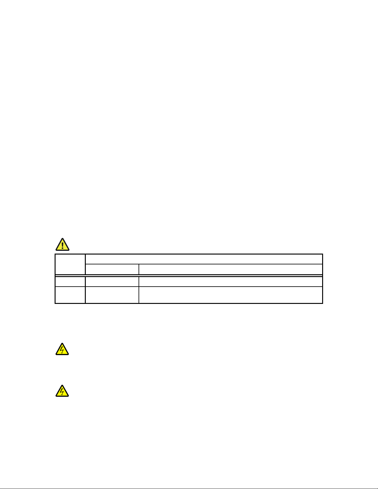
The basic components of the filter wheel mechanical assembly are shown below in Figure 1-1
and Figure 1-2. The only components that are to be removed by the user are the drop-in or
slide in filter holders and the plug in the loading port. At no time should the user remove the
cover plate from the wheel housing.
1
Tabletop controller box is available upon request.
2
Uniblitz® is a registered trademark of Vincent Associates.
LAMBDA 10-2 OPERATION MANUAL – REV. 2.04 (20120224)
Page 11
3
Figure 1-1. Lambda 10-2 Filter Wheel (without shutter)
Figure 1-2. Lambda 10-2 filter wheel housing (with shutter)
1. 10-position wheel (removed from motor hub
2. Installed filter cup
3. Wheel housing
4. Cover plate (removed from wheel housing
5. Stepper motor
6. Drop-in filter holder (Figure 1-1) or slide-in filter holder (Figure 1-2)
7. Mounting ears
8. Optical port
9. Loading port (plug installed)
10. Shutter housing
All filter wheel options are listed in the Sutter Instrument catalogue and in the following
list.
10
10----position, 25mm filter wheels:
position, 25mm filter wheels:
1010
position, 25mm filter wheels:position, 25mm filter wheels:
LB10
LB10----NW
LB10LB10
NW (without shutter)
NWNW
LB10
LB10----NWS
LB10LB10
NWS (with shutter)
NWSNWS
LAMBDA 10-2 OPERATION MANUAL – REV. 2.04 (20120224)
Page 12

4
LB10
LB10----NWE
LB10LB10
LB10
LB10----WD
LB10LB10
LB10
LB10----WDS
LB10LB10
NWE (without shutter and set up for emission)
NWENWE
WD (two wheels mounted back to back, without shutter)
WDWD
WDS (two wheels mounted back to back, with one shutter and one slide-in filter
WDSWDS
holder)
10
10----position 32mm filter wheels:
position 32mm filter wheels:
1010
position 32mm filter wheels:position 32mm filter wheels:
LB10
LB10----W32
LB10LB10
LB10
LB10----W32S
LB10LB10
5555----position 50mm filter wheel:
LB10
LB10----W50
LB10LB10
W32 (without shutter)
W32W32
W32S (with shutter)
W32SW32S
position 50mm filter wheel:
position 50mm filter wheel:position 50mm filter wheel:
W50 (without shutter).
W50W50
NOTE: All shutters mentioned in this manual for use with the Lambda 10
NOTE: All shutters mentioned in this manual for use with the Lambda 10----2 are
NOTE: All shutters mentioned in this manual for use with the Lambda 10NOTE: All shutters mentioned in this manual for use with the Lambda 10
shutters.
shutters.
shutters.shutters.
1.2.3
1.2.3 Filters
Filters
1.2.31.2.3
FiltersFilters
2 are Uniblitz
2 are 2 are
®®®®3333
The Lambda 10-2 filter changer is designed for use with any 1-inch or 25-mm filter with a
thickness that does not exceed the following dimensions:
4.5 mm (0.18 in.) for Slide
4.5 mm (0.18 in.) for Slide----in filter holders
4.5 mm (0.18 in.) for Slide4.5 mm (0.18 in.) for Slide
5.38 mm (0.21 in.) for Drop
5.38 mm (0.21 in.) for Drop----in filter holders
5.38 mm (0.21 in.) for Drop5.38 mm (0.21 in.) for Drop
9 mm (0.35 in.) for filter cups
9 mm (0.35 in.) for filter cups
9 mm (0.35 in.) for filter cups9 mm (0.35 in.) for filter cups
in filter holders
in filter holdersin filter holders
in filter holders
in filter holdersin filter holders
Filter wheels designed for use with 32 mm filters will accept filters with a thickness that
does not exceed the following dimensions:
9 mm (0.35 in.) for filter cups
9 mm (0.35 in.) for filter cups
9 mm (0.35 in.) for filter cups9 mm (0.35 in.) for filter cups
Instructions for installing filters into the filter wheel can be found in the FILTER WHEEL
chapter of this manual. Filters are not supplied by Sutter Instru
conforming to the above specifications can be purchased from any filter manufacturer.
conforming to the above specifications can be purchased from any filter manufacturer.
conforming to the above specifications can be purchased from any filter manufacturer.conforming to the above specifications can be purchased from any filter manufacturer.
1.2.4
1.2.4 Slide
Slide----In and Drop
1.2.41.2.4
In and Drop----In Filter Holders
SlideSlide
In and DropIn and Drop
Filters are not supplied by Sutter Instrument. However, filters
Filters are not supplied by Sutter InstruFilters are not supplied by Sutter Instru
In Filter Holders
In Filter HoldersIn Filter Holders
ment. However, filters
ment. However, filters ment. However, filters
Many users like to have extra Slide-in or Drop-in filter holders for more convenient
replacement of these “fixed” filters. Only use filter holders made by Sutter Instrument
Company in the Lambda 10
Company in the Lambda 10----2 Filter Wheel.
Company in the Lambda 10Company in the Lambda 10
2 Filter Wheel. Extra filter holders are readily available from
2 Filter Wheel. 2 Filter Wheel.
Only use filter holders made by Sutter Instrument
Only use filter holders made by Sutter Instrument Only use filter holders made by Sutter Instrument
Sutter Instrument Company or their distributors and are listed as “SLIDE-IN” and “DROPIN” in the Sutter catalogue. At this point, there are no slide-in filter holders for 32 mm
systems, although a 32-mm Drop-in filter holder is available. In addition, there is a fixed
filter position for a heat-blocking filter in most 32-mm microscope adapters offered by Sutter
Instrument Company. Slide-in and drop-in filter holders are not available for the 50 mm
filter wheels.
1.2.5
1.2.5 Shutters
Shutters
1.2.51.2.5
ShuttersShutters
If you purchase a Lambda 10-2 Filter Wheel system without a shutter and later decide to add
one to the system, the Filter Wheel must be returned to the factory for the upgrade. The
Lambda 10-2 Filter Wheel controller can support a retrofit shutter without modification.
3
Uniblitz® is a registered trademark of Vincent Associates.
LAMBDA 10-2 OPERATION MANUAL – REV. 2.04 (20120224)
Page 13

5
However, you must
you must only use shutters installed by Sutter Instrume
you mustyou must
only use shutters installed by Sutter Instrument.
only use shutters installed by Sutter Instrumeonly use shutters installed by Sutter Instrume
nt. This upgrade is
nt. nt.
available only at Sutter Instrument’s factory (or through their distributors) and is listed as
“SHUTTER” in the Sutter catalogue (or “WHEEL” in older catalogues).
1.2.6
1.2.6 Adapters
Adapters
1.2.61.2.6
AdaptersAdapters
Most microscopes, cameras, light sources and other optical instruments to which the Lambda
10-2 may be interfaced will require some sort of adapter to link the devices. Adapters for
interfacing the filter wheel to most instruments are available from Sutter Instrument or can
be custom built by Sutter Instrument. Suitable adapters are available from other sources,
as well, but Sutter Instrument assumes no responsibility for the performance, suitability
as well, but Sutter Instrument assumes no responsibility for the performance, suitability
as well, but Sutter Instrument assumes no responsibility for the performance, suitability as well, but Sutter Instrument assumes no responsibility for the performance, suitability
and safety of adapters built by the user or other manufacturers.
and safety of adapters built by the user or other manufacturers.
and safety of adapters built by the user or other manufacturers.and safety of adapters built by the user or other manufacturers.
1.2.7
1.2.7 Other and Optional Acce
Other and Optional Accessories
1.2.71.2.7
Other and Optional AcceOther and Optional Acce
ssories
ssoriesssories
Suitable adapters are available from other sources,
Suitable adapters are available from other sources, Suitable adapters are available from other sources,
1.2.7.1 Liquid Light Guide (LLG)
A 2-meter, 3mm diameter liquid light guide is optionally available from Sutter Instrument
(P/N: LLG). The LLG includes a C-mount, lens, and lens tube.
1.3
1.3 Functional Description
Functional Description
1.31.3
Functional DescriptionFunctional Description
1.3.1
1.3.1 Stepping Motor Operation
Stepping Motor Operation
1.3.11.3.1
Stepping Motor OperationStepping Motor Operation
Stepping motors are not as familiar to most people as the common DC motor, but there are
some similarities. The DC motor consists of an armature, an electromagnet mounted on a
rotating shaft, which is located inside a permanent magnet. Current is supplied to the
electromagnet through brushes that rub on contacts on the armature. When the
electromagnet is energized, the armature rotates to align the poles of the electromagnet with
the opposite poles of the permanent magnet. Of course, before this can occur, the rotation of
the armature changes the contact plates rubbing on the brushes so that the current is
reversed. This causes the poles of the electromagnet to reverse, establishing a force for
continued rotation. This switching action is called commutation.
In stepping motors, the rotating element, called a rotor, is generally a permanent magnet
while the fixed element, the stator, is the electromagnet. The key difference between
stepping motors and DC motors, however, is the method of commutation. The DC motor
commutates automatically as it rotates. Thus, the timing of the commutation is determined
by the speed of rotation, which may vary with the load or applied power. The commutation of
the stepping motor is set by external electronics, forcing the motor to rotate at a
predetermined rate. If the load is such that the motor does not have the force to produce the
correct rate of rotation, the rotation will become erratic and may even reverse.
The force exerted between two magnet poles is proportional to the square of the distance
between the poles. A motor with a single electromagnet and only two poles would exhibit
considerable loss of power when the distance between the poles of the permanent magnet
and the electromagnet was greatest. It is understandable that, in most practical DC motors,
the armature has more than two poles. This allows the commutation to occur over a smaller
angle of rotation, so that the active poles can always be relatively close to the poles of the
permanent magnet.
LAMBDA 10-2 OPERATION MANUAL – REV. 2.04 (20120224)
Page 14

6
Stepping motors are also made with multiple poles on both the rotor and stator the exact
arrangement determines the number of steps per revolution. The motor used in the Lambda
10-2 has 200 steps per revolution (1.8 degrees per step). There are usually two windings in
the stator, and a single step of rotation is produced by reversing the current on one of the
windings. Reversing the current on the second winding will then produce another step. If the
first winding is then reversed again, returning to its original value, a third step will result.
Finally, reversing the second winding, so that both windings are back to their original state,
will produce a fourth step. This pattern may then be repeated to continue rotation in the
same direction. Reversing the sequence produces steps of rotation in the opposite direction.
The rate and distance of rotation is determined by the rate and number of commutation
steps. As long as the current is held constant in both windings, the rotor will not rotate. This
makes the stepping motor ideal for producing fast start and stop movements. Some
limitations should be considered. Given that there are only 4 states of the control electronics
(2 polarities for each of the 2 windings) but 200 steps per revolution, it follows that, for each
of these four states, there are 50 possible rotary positions. In order to establish the absolute
position an external sensor must be added. Absolute position only needs to be determined
once so long as the subsequent moves occur without errors.
Correct operation of stepping motors, which is outlined above, is not always obtained. If the
motor lacks the torque to accelerate and decelerate the load at the rate indicated by the
control electronics, the resulting move may differ from that commanded by the control
electronics. For instance, if enough external force is applied, the motor shaft may be rotated
even though the command signal has not changed. For small rotations (less than 3.6
degrees), the motor shaft will return to the correct position if the force is removed. For
larger rotations, the shaft will stop at the nearest of the 50 correct positions for that
command signal when the external force is removed.
LAMBDA 10-2 OPERATION MANUAL – REV. 2.04 (20120224)
Page 15

2.
2. IN S TAL LAT ION
INS TAL LAT ION
2.2.
INS TAL LAT IONIN STA LLA TIO N
2.1
2.1 Unpacking
Unpacking
2.12.1
UnpackingUnpacking
The Lambda 10-2 and associated hardware comes packed in a single carton. The following is
a list of the components found there. If two wheels were ordered, two of everything should
have been received (except those items marked with an asterisk (*)). If you believe that any
of these components are missing or show obvious signs of damage from shipping, please
contact the factory.
1 or 2 Filter Wheels, each a 10 position 25 or 32 mm, or 5
1 or 2 Filter Wheels, each a 10 position 25 or 32 mm, or 5----position 50 mm, and each
1 or 2 Filter Wheels, each a 10 position 25 or 32 mm, or 51 or 2 Filter Wheels, each a 10 position 25 or 32 mm, or 5
with or without a shutter (25 or 35 mm
with or without a shutter (25 or 35 mm
with or without a shutter (25 or 35 mmwith or without a shutter (25 or 35 mm
Lambda 10
Lambda 10----2 Controller*
Lambda 10Lambda 10
Support Base per filter wheel
Support Base per filter wheel
Support Base per filter wheelSupport Base per filter wheel
2 Support Rods p
2 Support Rods per filter wheel
2 Support Rods p2 Support Rods p
2 Base Clamps per filter wheel
2 Base Clamps per filter wheel
2 Base Clamps per filter wheel2 Base Clamps per filter wheel
Filter Wheel to Controller Connecting Cable (1 per filter wheel)
Filter Wheel to Controller Connecting Cable (1 per filter wheel)
Filter Wheel to Controller Connecting Cable (1 per filter wheel)Filter Wheel to Controller Connecting Cable (1 per filter wheel)
Parallel Interface Cable*
Parallel Interface Cable*
Parallel Interface Cable*Parallel Interface Cable*
Serial Interface Cable*
Serial Interface Cable*
Serial Interface Cable*Serial Interface Cable*
Power Cord*
Power Cord*
Power Cord*Power Cord*
2 Individual Filter Holders (per filter wheel)
2 Individual Filter Holders (per filter wheel)
2 Individual Filter Holders (per filter wheel)2 Individual Filter Holders (per filter wheel)
Retaining Ring Driver*
Retaining Ring Driver*
Retaining Ring Driver*Retaining Ring Driver*
Manual*
Manual*
Manual*Manual*
Micr
Microscope Adapters (if ordered)
oscope Adapters (if ordered)
MicrMicr
oscope Adapters (if ordered)oscope Adapters (if ordered)
2 Controller*
2 Controller*2 Controller*
er filter wheel
er filter wheeler filter wheel
position 50 mm, and each
position 50 mm, and each position 50 mm, and each
Each 10-position filter wheel is shipped with nine positions of the wheel containing retaining
rings, spacer rings and blanking discs. One of the individual filter holders contains the same
three components. The second individual filter holder and one position of the wheel (position
#1) contain only retainers and spacers.
7
The Lambda 10-2 is shipped to you in a prefabricated foam mold. Please take note of this
method of packaging. Should it ever be necessary to ship the puller to another location, the
same method of packaging should be employed. Additional packing material may be
purchased from Sutter Instruments.
IMPORTANT: Improper packaging is a form of abuse and, as such, can be responsible for
voiding the warranty where shipping damage is sustained because of such packing.
2.2
2.2 Pre
Pre----installation Considerations
2.22.2
2.2.1
2.2.1 Vibrations
2.2.12.2.1
installation Considerations
PrePre
installation Considerationsinstallation Considerations
Vibrations
VibrationsVibrations
The Lambda 10-2 filter wheel system was designed to produce fast filter changes with a
minimum of vibration. The microprocessor controls the trajectory of each move using
microsteps with programmed acceleration and deceleration profiles. The result is a system so
smooth that customers using the Lambda 10 for the first time have called to report that
their wheel isn’t turning simply because they could not hear or feel anything.
LAMBDA 10-2 OPERATION MANUAL – REV. 2.04 (20120224)
Page 16

8
Although the Lambda 10-2 is smooth and quiet, even the slightest vibration can produce
problems for the electrophysiologist. Vibration can come from several sources. The most
pronounced effects normally come from the high-speed shutter, if that option has been
included. The shutter produces a very sharp impulse which is best avoided by finding
another way of turning the light on and off such as turning to a blanked filter position.
When the motor accelerates and decelerates the filter wheel rapidly, the torque applied tends
to turn the motor and the Lambda housing in the opposite direction. If the housing is not
firmly attached, this may appear as vibration that increases with the selected speed and the
weight of filters loaded. This is not usually a problem if the wheel is firmly mounted to a
good solid surface.
Stepping motor-based systems can produce considerable vibration and noise if the rate at
which steps are taken excites a system resonance. This problem is greatly reduced by
reducing the step size with microstepping, as in the Lambda 10-2. Even when microstepping
is used, it is possible to produce vibration by selecting a speed that is not optimal or by
starting a new move within a few milliseconds of the end of the previous move. For example,
with only two typical filters loaded speed 1 should give a very smooth move that stops with
little vibration. Speed 2, 3, and 7 may all produce more vibration at the end of a move with
this load even though they are slower speeds.
At a minimum, we recommend that the Lambda 10-2 should be firmly mounted to a solid
surface by the support stand, which is included with each unit. Do not depend on the optical
coupling between the microscope and the Lambda 10 to support and stabilize the Lambda
10. This configuration will be adequate in many cases. If there is still too much vibration, the
wheel may be mounted using the support stand, but with an air gap between the Lambda 10
and the microscope.
The best cure for vibration is isolation. One simple approach is to mount the filter wheel to a
wall or a separate table. If the microscope is on an air table, be aware that the microscope
might drift relative to a filter wheel mounted on a separate, stable surface. In such cases, it
may be better to couple the Lambda 10 to the microscope with a flexible light guide. Contact
Sutter Instrument for detail of our light-guide adapter system.
2.3
2.3 Installing the Controller
Installing the Controller
2.32.3
Installing the ControllerInstalling the Controller
2.3.1
2.3.1 Line Po
Line Power (Mains)
2.3.12.3.1
Line PoLine Po
wer (Mains)
wer (Mains)wer (Mains)
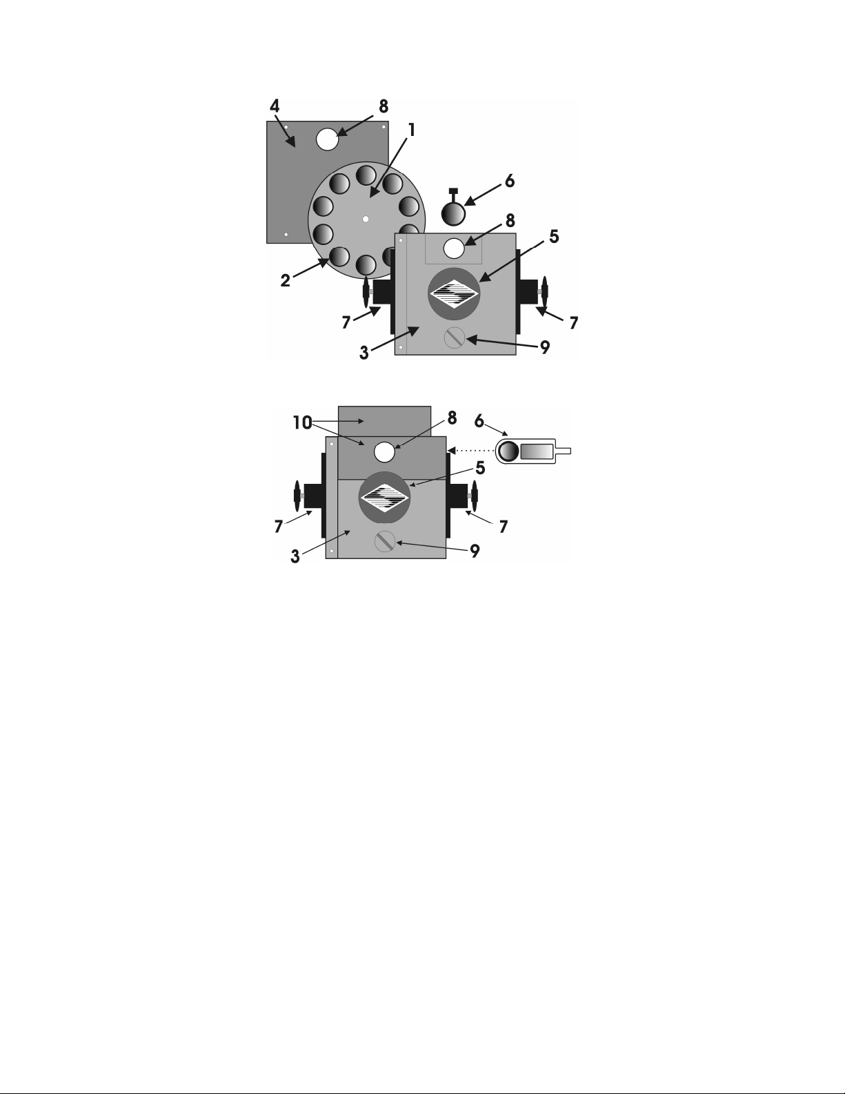
The power cord provided with the Lambda 10-2 connects to the Power Entry Module located
on the back of the unit (see Figure 2-1). This Module also includes the Line Fuse and Voltage
Selector Switch.
LAMBDA 10-2 OPERATION MANUAL – REV. 2.04 (20120224)
Page 17
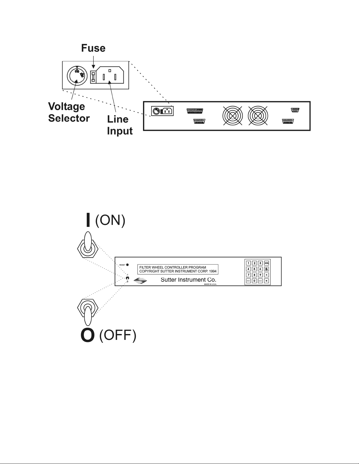
Figure 2-1. Lambda 10-2 Cabinet (rear view).
Confirm that the Voltage Selector Switch on the Power Entry Module is set to the proper
value (110V a.c. or 220V a.c.). If it is not, turn the selector switch until the appropriate value
is lined up with the indicator. You must also replace the fuse with the appropriate value (see
the Technical Specifications), otherwise your protection from fire and electric shock may be
compromised.
9
Make certain that the ON/OFF Switch located on the front panel of the Lambda 10-2 cabinet
is turned OFF.
Figure 2-2. Lambda 10-2 Cabinet (front view)
Plug the power cord provided with the Lambda 10-2 into the Line Input socket on the Power
Entry Module and then to a power source of the appropriate voltage and frequency.
LAMBDA 10-2 OPERATION MANUAL – REV. 2.04 (20120224)
Page 18
10
Figure 2-3. Power connection
2.4
2.4 Installing the Filter Wheel
Installing the Filter Wheel
2.42.4
Installing the Filter WheelInstalling the Filter Wheel
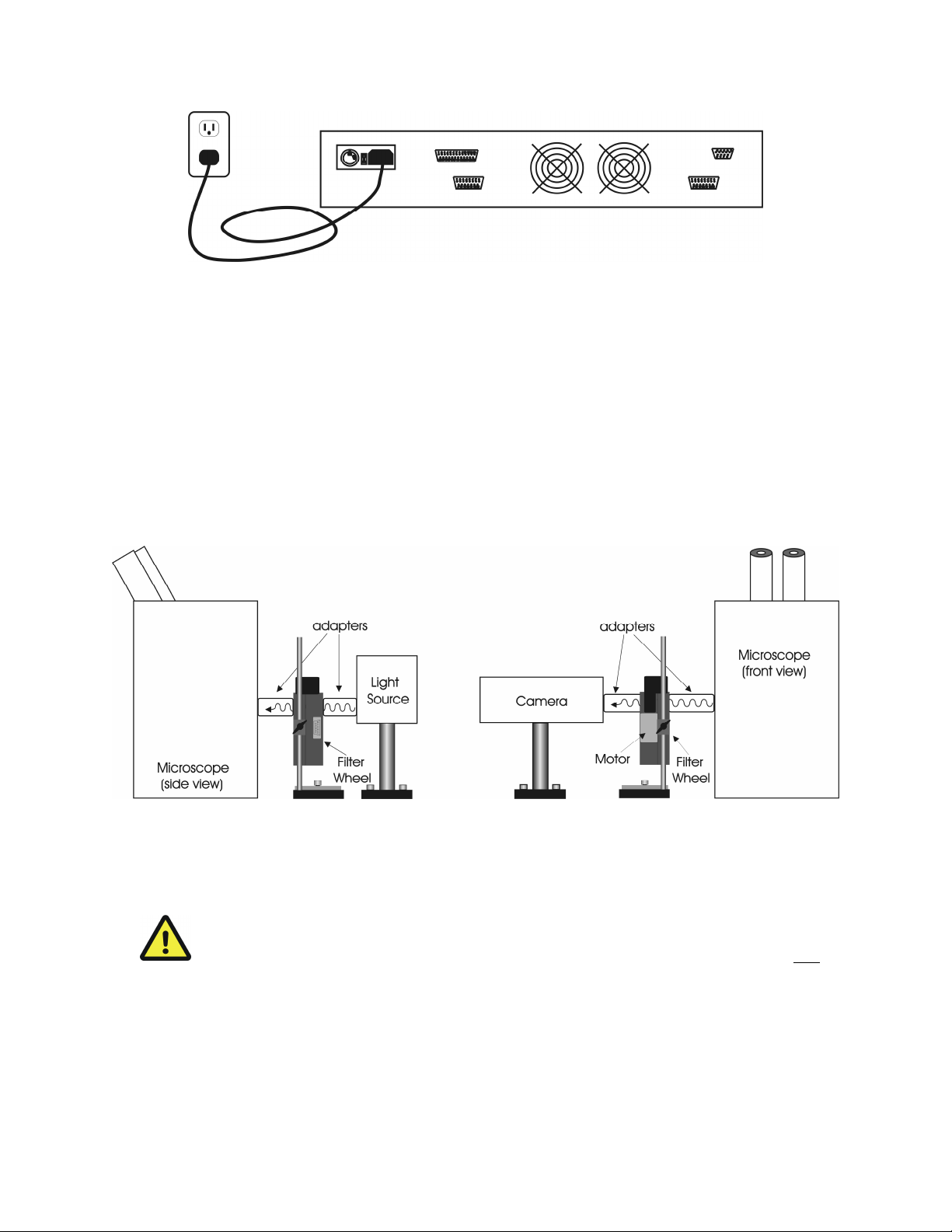
If you have not yet mounted the filter wheel on the support hardware, please refer to the
FIRST TIME USE chapter of this manual for instructions. Now move the mounted filter
wheel to the approximate final location and adjust the filter wheel to the desired height. The
filter wheel can be mounted on the posts in either orientation (optical port up or down), as
required. The filter wheel can now be interfaced with other instruments (e.g. a microscope
and a light source) using an appropriate adapter (Figure 2-4). If you need to purchase an
adapter or require a custom adapter for your experimental setup, please contact the
Technical Support staff at Sutter Instrument Company by phone (415 883-0128) or by Email (info@sutter.com).
Figure 2-4. Schematic diagram of two possible experimental configurations
The optical ports in the filter wheel housing and cover plate are threaded 1-32 (standard Cmount) allowing direct connection of like-threaded devices (camera adapters, microscope
adapters, etc.)
project more than 0.180 inches into the port. Allow
project more than 0.180 inches into the port. Allowing threaded devices to penetrate
project more than 0.180 inches into the port. Allowproject more than 0.180 inches into the port. Allow
further could result in damage to the filter wheel or filter cups.
further could result in damage to the filter wheel or filter cups.
further could result in damage to the filter wheel or filter cups. further could result in damage to the filter wheel or filter cups.
CAUTION
CAUTION: Care should be taken that any devices threaded into the ports
CAUTION CAUTION
: Care should be taken that any devices threaded into the ports not
: Care should be taken that any devices threaded into the ports : Care should be taken that any devices threaded into the ports
ing threaded devices to penetrate
ing threaded devices to penetrate ing threaded devices to penetrate
not
notnot
Once the filter wheel has been attached to the other instrument(s), tighten the wing screws
to lock the filter wheel at its final height. It is intended that the filter wheel be supported on
the two posts included with your system. These posts can be screwed into the base provided
or into any surface with ¼”-20 holes drilled on 6” centers at an appropriate position on the
LAMBDA 10-2 OPERATION MANUAL – REV. 2.04 (20120224)
Page 19
11
tabletop or optical bench. When using the support rod base always secure it to the tabletop
using the toe clamps provided with the system.
If a heavy light source is to be used (such as a vapor lamp with integral igniter) it should
have its own separate support system.
If your filter wheel has a shutter, the side of the filter wheel on which the shutter is installed
(the “motor side” as shown in Figure 2-4) would typically be mounted toward the light
source. Placing the shutter between the lamp and filters limits the amount of heat and light
to which the filters are exposed and increases the filters’ useful lifetime.
2.4.1
2.4.1 Filter Wheel Assembly Set Up
Filter Wheel Assembly Set Up
2.4.12.4.1
Filter Wheel Assembly Set UpFilter Wheel Assembly Set Up
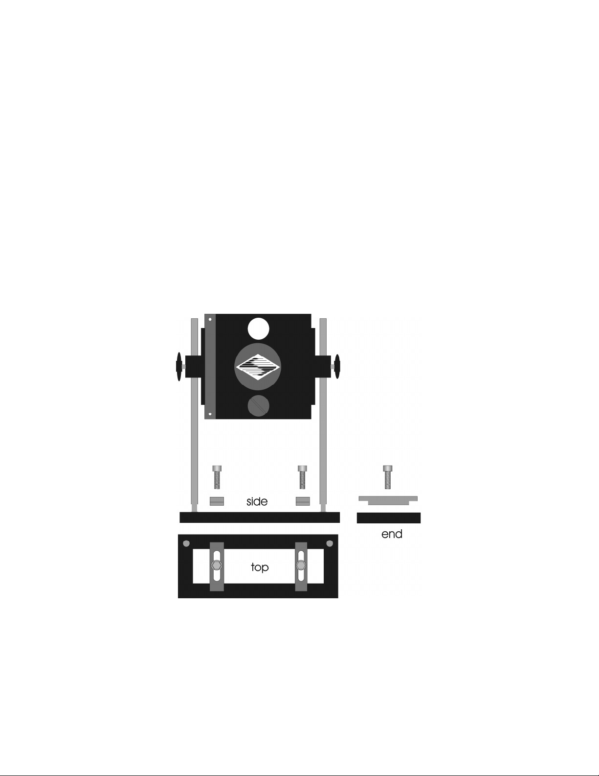
1. Assemble the two Support Rods to the Support Base. Flats have been machined near the
threaded end of these rods to facilitate tightening with a wrench. The pair of support
base clamps should be used to anchor the base to some convenient location for testing.
These clamps are designed to allow anchoring to any of the popular hole-patterns found
in optical benches.
2. Slide the filter wheel down onto the support rods and lock it at a convenient height using
the wing screws on the mounting ears of the filter wheel.
Figure 2-5. Filter wheel mounting stand
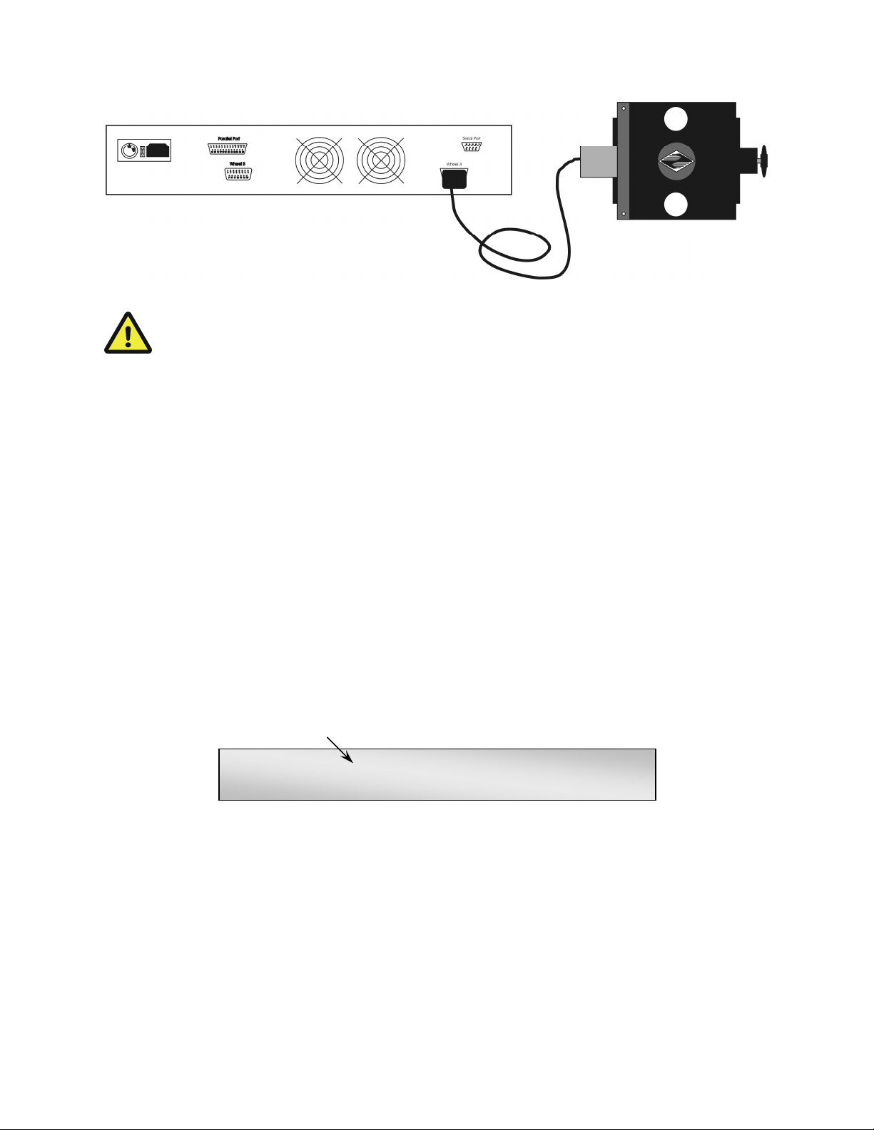
3. Connect the controller and filter wheel(s) with the appropriate cable(s) provided. It is
important that the screws anchoring the cable ends be tight to ensure a good connection
for the motor power leads and positioning signals.
LAMBDA 10-2 OPERATION MANUAL – REV. 2.04 (20120224)
Page 20
12
Figure 2-6. Filter wheel connection
CAUTION:
CAUTION: DO NOT CONNECT OR DISCONNECT THE CABLES BETWEEN
CAUTION: CAUTION:
THE CONTROLLER AND THE MECHANICAL UNITS (FILTER WHEELS AND/OR
THE CONTROLLER AND THE MECHANICAL UNITS (FILTER WHEELS AND/OR
THE CONTROLLER AND THE MECHANICAL UNITS (FILTER WHEELS AND/OR THE CONTROLLER AND THE MECHANICAL UNITS (FILTER WHEELS AND/OR
SHUTTER
SHUTTERS) WHILE POWER IS ON.
SHUTTERSHUTTER
S) WHILE POWER IS ON.
S) WHILE POWER IS ON. S) WHILE POWER IS ON.
DO NOT CONNECT OR DISCONNECT THE CABLES BETWEEN
DO NOT CONNECT OR DISCONNECT THE CABLES BETWEEN DO NOT CONNECT OR DISCONNECT THE CABLES BETWEEN
Please allow at least 20 seconds after turning the unit off before disconnecting the
Please allow at least 20 seconds after turning the unit off before disconnecting the
Please allow at least 20 seconds after turning the unit off before disconnecting the Please allow at least 20 seconds after turning the unit off before disconnecting the
mechanical units. Failure to do this may result in damage to the electronics.
mechanical units. Failure to do this may result in damage to the electronics.
mechanical units. Failure to do this may result in damage to the electronics.mechanical units. Failure to do this may result in damage to the electronics.
2.5
2.5 First Time Use
First Time Use
2.52.5
First Time UseFirst Time Use
Make certain that the Lambda 10-2 controller is properly connected to the mains power
(refer to Section 2.3.1 and to Figure 2-1 and Figure 2-2).
2.5.1
2.5.1 Make It Go
Make It Go
2.5.12.5.1
Make It GoMake It Go
1. Turn on the power using the ON/OFF switch on the front panel of the Lambda 10-2
controller cabinet (see Figure 2-2). The controller will briefly display an initialization
screen and the filter wheel will automatically go to the “Home” (0) filter position. The
current filter position will appear on the controller front panel display.
Filter position currently
selected on Filter Wheel A
FILTER-A # 0 SP. 2 B NOT CONNECTED
PARALLEL SHUTTER A-OFF B-OFF
Figure 2-7. Initialization screen.
2. The Lambda 10-2 will initially be set to respond to the parallel port as its input source.
To manually select a filter you must first press the LOCAL key on the keypad. The
display will now indicate that the MANUAL (keypad) input source is active.
LAMBDA 10-2 OPERATION MANUAL – REV. 2.04 (20120224)
Page 21

13
FILTER-A # 0 SP. 2 B NOT CONNECTED
MANUAL-A SHUTTER A-OFF B-OFF
Input source currently
selected (MANUAL=keypad)
Figure 2-8. Initialization screen in local mode.
3. Press any numeric key on the keypad to manually select the corresponding filter position.
4. To select the filter wheel speed press the SPEED key on the keypad. The display will
prompt you through the SPEED change routine. The smaller the number you enter (0 to
7), the faster the filter wheel will move. The default SPEED setting upon startup is 2.
5. If a shutter is installed, press the SHUTR key on the keypad to toggle the shutter open
and closed. See the MANUAL CONTROL chapter for a more detailed description of
shutter operation.
Now that you have completed this FIRST TIME USE section of this manual, you should be
familiar with the basic components and the MANUAL operation of the Lambda 10-2. To get
set up for an experimental application you will need to:
Install the desired filters into the FILTER WHEEL.
Install the filter wheel into the optical pathway using the appropriate adapter.
Establish the desired INTERFACE between the Lambda 10-2 and your computer.
Each of these steps is discussed in the following sections of the manual.
2.6
2.6 Loading Filters
Loading Filters
2.62.6
Loading FiltersLoading Filters
2.6.1
2.6.1 Filter Orientation
Filter Orientation
2.6.12.6.1
Filter OrientationFilter Orientation
The two sides of a filter are usually not identical due to differences in their surface coatings.
Some form of labeling will be present to differentiate the two sides if this is the case. It is
important to refer to the filter manufacturer’s documentation to interpret the labeling and
determine the proper orientation relative to the light source.
2.6.2
2.6.2 Filter Cups and Filter Holders
Filter Cups and Filter Holders
2.6.22.6.2
Filter Cups and Filter HoldersFilter Cups and Filter Holders
At each filter position on the filter wheel, is a filter cup assembly to hold one 1” filter. The
Lambda 10-2 also comes with two removable 1” filter holders that can be placed into the
optical pathway to accommodate “fixed” filters, such as neutral density filters. The filter
holders will be either a “drop in” style if no shutter is installed (item 6 in Figure 1-1) or a
“slide in” style if a shutter is installed (item 6 in Figure 1-2).
There are at least two components installed into each filter cup or holder before the Lambda
10-2 is shipped: a threaded retaining ring to secure the filter into the cup (or holder), and a
spacer ring. In all but one of the filter cups, and in one of the filter holders, there will also be
a blanking disc. Figure 2-9 depicts these items using the drop-in filter holder as an example.
LAMBDA 10-2 OPERATION MANUAL – REV. 2.04 (20120224)
Page 22

14
Figure 2-9. Filter holder components
Retaining Ring.
Retaining Ring. This ring is threaded on its outside surface and has two slots on its top
Retaining Ring. Retaining Ring.
edge. It is intended that the two slots be used for the removal and installation of the
retaining ring when using the spanner wrench that is provided with the Lambda 10-2
(shown in Figure 2-9). Note how the design of the spanner wrench differs between 25, 32,
and 50 mm filter sizes.
SSSSpacer Ring.
pacer Ring. This ring is unthreaded and serves to evenly carry the force of the retaining
pacer Ring. pacer Ring.
ring to the bottom of the filter cup or holder. It is recommended that the spacer be used
anytime a blanking disc is installed or the filter cup or holder is. The spacer ring should
also be used whenever the thickness of an installed filter allows its use. Maximum filter
thicknesses for the filter cup and holders are specified below in Table 2-1.
Blanking Disc.
Blanking Disc. In all but one of the filter cups (and one of the filter holders), there will
Blanking Disc.Blanking Disc.
also be a blanking disc. These are meant to prevent transmission of the high intensity
light to the microscope through unused filter positions. This is primarily a safety feature,
which reduces the probability that the operator will look into the optical pathway when
dangerous, high intensity, unfiltered light is present and magnified. A blanking disc in a
filter cup can also function as a shutter in an experimental protocol.
LAMBDA 10-2 OPERATION MANUAL – REV. 2.04 (20120224)
Page 23

Table 2-1. Maximum allowable filter thickness.
15
With Spacer
(Millimeters) (Inches) (Millimeters) (Inches)
Slide
Slide----in holder
in holder 1.38 0.054 4.56 0.18
SlideSlide
in holderin holder
Drop
Drop----in holder
in holder 2.2 0.086 5.38 0.212
DropDrop
in holderin holder
Filter cup
Filter cup 5.89 0.2315 9.07 0.3575
Filter cupFilter cup
2.6.3
2.6.3 Installation of Filters into Filter Holders
Installation of Filters into Filter Holders
2.6.32.6.3
Installation of Filters into Filter HoldersInstallation of Filters into Filter Holders
With Spacer Without Spacer
With SpacerWith Spacer
Without Spacer
Without SpacerWithout Spacer
Installation of filters into the filter holders requires care and patience to avoid damaging the
threads as well as the filters. The following procedures describe this process and should be
practiced with a drop-in (or slide-in) filter holder before attempting to load filters into the
filter cups.
Figure 2-10. Removing the retaining ring
The threaded retaining ring has two notches cut into it, 180 degrees apart. Place the teeth
(for 25mm; Figure 2-10) or notches (32 or 50 mm) of the spanner wrench into the notches on
the retaining ring and carefully turn it counter-clockwise to unscrew it.
Once the retaining ring is removed, the spacer (and blank, if present) should be easily
removed. You should become familiar with the assembly of this retaining system. In
particular, you should develop a feel for turning the retaining ring without pushing down on
the driver or wrench. This is important because if you forcefully push on the filter holder
while you are trying to load a filter, you run the risk of scratching the filter if the tool slips
out of place!
LAMBDA 10-2 OPERATION MANUAL – REV. 2.04 (20120224)
Page 24

16
Figure 2-11. Installing a filter into a Slide-In Filter Holder.
Figure 2-12. Assembly order of filter holder parts
Place the desired filter into the filter holder, first. With some 1” filters extra care must be
taken to avoid getting the filters jammed at an angle.
Next, install the spacer ring into the filter holder. Unless the filter thickness precludes the
use of the spacer ring (see Figure 2-12), always install the spacer. This helps to provide
maximum separation between the filter surface and end of the tool that is used to turn the
retaining ring.
Finally, install the threaded retaining ring. DO NOT OVER TIGHTEN THE RETAINING
RING! It need only be tightened until it is firmly seated.
2.6.4
2.6.4 Installation of Filters into Filter Cups
Installation of Filters into Filter Cups
2.6.42.6.4
Installation of Filters into Filter CupsInstallation of Filters into Filter Cups
Loading filters into the filter cups on the filter wheel follows the same procedure as
described above for loading filters into filter holders. There is, however, the additional
complication of working through the filter wheel housing. To gain access to the filter cups on
LAMBDA 10-2 OPERATION MANUAL – REV. 2.04 (20120224)
Page 25

17
the wheel, unscrew the access plug from the loading port on the motor housing (i.e., the
motor side of the filter wheel). A large coin or other suitable implement can be used to
remove the plug. Once removed, the retaining ring in the underlying filter cup is accessible
through that port.
To align the filter position you wish to load with the loading port, it is easiest to use the
controller to identify and position the filter cups. To begin, connect the Filter Wheel to the
controller (see the FIRST TIME USE chapter for a brief description of the principles of
operation). When you first turn on the controller, the Filter Wheel will “HOME” itself,
aligning the “0” filter position with the Optical Port and filter position #5 with the Loading
Port. The filter being in the Loading Port is five positions removed from the one indicated by
the controller display (i.e., the one at the OPTICAL PORT). This relationship between the
filter position indicated by the controller and the filter position at the LOADING PORT is
illustrated in Figure 2-13.
Filter position at optical port 0 1 2 3 4 5 6 7 8 9
Filter position at loading port 5 6 7 8 9 0 1 2 3 4
Figure 2-13. Filter ports (plug is removed from the loading port)
After identifying and positioning the filter cup to be loaded, it is advisable to turn off the
controller before removing the retaining ring from the filter cup. Follow the procedures
described above for installation of filters into filter holders.
LAMBDA 10-2 OPERATION MANUAL – REV. 2.04 (20120224)
Page 26

18
CAUTION: An extra word of caution about excessive force is warranted at this
CAUTION: An extra word of caution about excessive force is warranted at this
CAUTION: An extra word of caution about excessive force is warranted at this CAUTION: An extra word of caution about excessive force is warranted at this
point.
point. DO NOT APPLY EXCESSIVE FORCE! Not only do you run the risk of
point. point.
damaging the filter but also the filter wheel itself can be permanently distorted by
damaging the filter but also the filter wheel itself can be permanently distorted by
damaging the filter but also the filter wheel itself can be permanently distorted by damaging the filter but also the filter wheel itself can be permanently distorted by
pushing too hard against the retaining ring with the driver or wrench. If you
pushing too hard against the retaining ring with the driver or wrench. If you
pushing too hard against the retaining ring with the driver or wrench. If you pushing too hard against the retaining ring with the driver or wrench. If you
experience problems securing th
experience problems securing the retaining ring, back the ring off the filter cup and try
experience problems securing thexperience problems securing th
again.
again.
again.again.
After loading the filter(s), check each newly loaded filter position to make sure that the
retaining ring is not projecting above the top edge of the filter cup then replace the loading
port plug.
Another potential complication of loading filters into the filter cups can occur if the retaining
ring has been previously over-tightened. In this case, it is possible that the filter cup itself
will begin to unscrew from the wheel as the retaining ring is turned. If this occurs, STOP!
Turn the spanner wrench so that the widest end is toward the filter cup and slip the wrench
into the two notches in the edge of the cup. Then turn the wrench clockwise to screw the cup
back into the slider. DO NOT push on the cup. Just screw it in until it seats firmly. It should
then be possible to remove the retaining ring as described above without the cup turning.
DO NOT APPLY EXCESSIVE FORCE! Not only do you run the risk of
DO NOT APPLY EXCESSIVE FORCE! Not only do you run the risk of DO NOT APPLY EXCESSIVE FORCE! Not only do you run the risk of
e retaining ring, back the ring off the filter cup and try
e retaining ring, back the ring off the filter cup and try e retaining ring, back the ring off the filter cup and try
It may appear that removal of the cover plate from the housing would facilitate loading
filters. This is not the case! Removal of the cover plate will not give you access to the filter
cup side of the wheel and may lead to misalignment of and damage to the Filter Wheel.
Under no conditions should y
Under no conditions should you ever remove the cover plate or the filter wheel from the
Under no conditions should yUnder no conditions should y
motor shaft
motor shaft. Removal of the cover plate or the wheel from the shaft will void your warranty.
motor shaftmotor shaft
2.7
2.7 Filter Loading Tips
Filter Loading Tips
2.72.7
Filter Loading TipsFilter Loading Tips
2.7.1
2.7.1 Selection of a Filter Position
Selection of a Filter Position
2.7.12.7.1
Selection of a Filter PositionSelection of a Filter Position
In most cases any given filter could be installed at any of the ten FILTER POSITIONS.
However, some minor considerations may improve performance of the system. Adjacent
FILTER POSITIONS will require less switching time. Therefore, if an experiment will
require rapid switching between 2 filters they should be located next to one another. If
separation by one or more occupied filter positions is necessary, keep in mind that there will
be brief transitions through, possibly, undesirable wavelengths as light transmits through
those intervening filter(s) unless a shutter is installed and programmed for use.
2.7.2
2.7.2 Use of Blanking Discs
Use of Blanking Discs
2.7.22.7.2
Use of Blanking DiscsUse of Blanking Discs
The blanking discs should only be removed from those positions that will contain a filter.
The discs are intended as a safety device to reduce the risk of the user sustaining serious and
permanent eye damage from looking in the microscope when dangerous high intensity light
is present. We strongly urge that the discs be used. Please be careful and avoid the possibility
of direct visualization of high intensity light.
ou ever remove the cover plate or the filter wheel from the
ou ever remove the cover plate or the filter wheel from the ou ever remove the cover plate or the filter wheel from the
2.7.3
2.7.3 Neutral Density Filters
Neutral Density Filters
2.7.32.7.3
Neutral Density FiltersNeutral Density Filters
The individual filter holders are typically used for neutral density filters and are installed as
described above.
LAMBDA 10-2 OPERATION MANUAL – REV. 2.04 (20120224)
Page 27

3.
3. OPE RAT ION S
OPE RATI ON S
3.3.
OPE RATI ON SOP ERAT ION S
3.1
3.1 First Time Use
First Time Use
3.13.1
First Time UseFirst Time Use
19
For first time use of the Lambda 10-2 during the installation process, please refer to Section
2.5 (First Time Use) in Chapter 2 (INSTALLATION).
3.2
3.2 Principles of Operation
Principles of Operation
3.23.2
Principles of OperationPrinciples of Operation
The Lambda 10-2 controller can be operated locally (manually) from the controller keypad or
remotely from a computer through either the parallel or serial port. These three operational
modes (manual, parallel and serial) are functionally identical. Each allows the user to select:
Active filter wheel
Filter position
Filter switching speed
Shutter position (opened/closed state)
The remainder of this chapter provides a detailed description of the controller’s rear panel
connectors and front panel controls. Information needed to connect the power cord and filter
wheel(s) is found in the FIRST TIME USE chapter. Instructions on operation of the
controller and control of the filter wheel(s) manually from the keypad are presented in the
MANUAL CONTROL chapter. The REMOTE CONTROL chapter explains control of the
unit from a remote device, as well as supplying some technical details relevant to local
operation. Technical details, which are not required for operation but which may help you
understand the behavior of the unit, are found in APPENDIX A: Stepping Motor Operation.
CAUTION:
CAUTION: DO NOT CONNECT OR DISCONNECT THE CABLES BETWEEN
CAUTION: CAUTION:
THE CONTROLLER AND THE MECHANICAL UNITS (FILTER WHEELS AND/OR
THE CONTROLLER AND THE MECHANICAL UNITS (FILTER WHEELS AND/OR
THE CONTROLLER AND THE MECHANICAL UNITS (FILTER WHEELS AND/OR THE CONTROLLER AND THE MECHANICAL UNITS (FILTER WHEELS AND/OR
SHUTTERS) WHILE POWER IS ON.
SHUTTERS) WHILE POWER IS ON.
SHUTTERS) WHILE POWER IS ON. SHUTTERS) WHILE POWER IS ON.
DO NOT CONNECT OR DISCONNECT THE CABLES BETWEEN
DO NOT CONNECT OR DISCONNECT THE CABLES BETWEEN DO NOT CONNECT OR DISCONNECT THE CABLES BETWEEN
Please allo
Please allow at least 20 seconds after turning the unit off before disconnecting the
Please alloPlease allo
mechanical units. Failure to do this may result in damage to the electronics.
mechanical units. Failure to do this may result in damage to the electronics.
mechanical units. Failure to do this may result in damage to the electronics.mechanical units. Failure to do this may result in damage to the electronics.
3.3
3.3 Rear Panel Connectors
Rear Panel Connectors
3.33.3
Rear Panel ConnectorsRear Panel Connectors
w at least 20 seconds after turning the unit off before disconnecting the
w at least 20 seconds after turning the unit off before disconnecting the w at least 20 seconds after turning the unit off before disconnecting the
All electrical connections are all made on the rear panel of the Lambda 10-2. See the FIRST
TIME USE chapter for details on connecting the power cord and filter wheel cable(s).
LAMBDA 10-2 OPERATION MANUAL – REV. 2.04 (20120224)
Page 28

20
Figure 3-1. Electrical connections
FILTER WHEEL (A and B):
FILTER WHEEL (A and B): These 15-pin DSUB connectors are used to link the Lambda 10-
FILTER WHEEL (A and B):FILTER WHEEL (A and B):
2 controller with the filter wheels (and shutters, if installed).
PARALLEL PORT
PARALLEL PORT: This 25-pin DSUB connector is used for establishing a parallel interface
PARALLEL PORTPARALLEL PORT
between the Lambda 10-2 and a remote device (computer) using the cable provided. This
cable should not be used simultaneously with the serial port cable.
SERIAL PORT
SERIAL PORT: This 9-pin DSUB connector is used for establishing a serial interface
SERIAL PORTSERIAL PORT
between the Lambda 10-2 and a remote device (computer) using the cable provided. This
cable should not be used simultaneously with the parallel port cable.
VOLTAGE SELECTOR
VOLTAGE SELECTOR: This switch selects the appropriate line voltage, 110 or 220 volts at
VOLTAGE SELECTORVOLTAGE SELECTOR
50 or 60 Hz, and is typically set at the factory before shipping.
LINE POWER
LINE POWER: This socket is used to connect the power cord to the Lambda 10-2.
LINE POWERLINE POWER
FUSE LABEL
FUSE LABEL: The information found on this label includes the model number of this
FUSE LABELFUSE LABEL
instrument, the appropriate supply voltage(s), and the type(s) of fuse(s) required for the
supply voltage(s).
FUSE
FUSE: Fuse compartment containing the supply voltage fuse and an extra fuse. Replace
FUSEFUSE
blown fuses with a fuse of the appropriate value as given on the fuse label (back panel of the
controller) or on the TECHNICAL SPECIFICATIONS page in this manual.
3.4
3.4 Front Panel Controls
Front Panel Controls
3.43.4
Front Panel ControlsFront Panel Controls
3.4.1
3.4.1 KKKKeypad
3.4.13.4.1
eypad
eypadeypad
Figure 3-2. Lambda 10-2 Controller Keypad
There are sixteen keys on the Lambda 10-2 keypad: Ten numerical keys (0 to 9), and six
function keys. The microprocessor that controls the Lambda 10-2 reads the keys while they
are depressed but the appropriate action will occur only when the key is released. If a key is
pressed while a move is in progress but released after the move is over, the key will read
normally. Keys pressed and released while a move is in progress are ignored.
LAMBDA 10-2 OPERATION MANUAL – REV. 2.04 (20120224)
Page 29

0000----9:
9: These keys are used to manually select filter positions and, with the SPEED key, to
9:9:
choose between the eight pre-set speeds.
SHUTR:
SHUTR: This key is used to manually open or close the shutter.
SHUTR:SHUTR:
SPEED:
SPEED: This key is used to access the SPEED selection mode.
SPEED:SPEED:
F1, F2:
F1, F2: These keys are used in MANUAL mode to select which Filter Wheel you wish to
F1, F2:F1, F2:
command through the keypad. (F1=Wheel A; F2=Wheel B).
LOCAL:
LOCAL: Pressing this key puts the unit under MANUAL (keypad) control. This function
LOCAL:LOCAL:
overrides all other input sources when pressed. This means that remote control through the
parallel or serial port will be interrupted if this key is pressed and then released between
executions of “ON LINE” commands.
ON LINE:
ON LINE: This key transfers control of the Lambda 10-2 to an interfaced external source,
ON LINE:ON LINE:
such as a computer. This transfer can also be done by sending the correct signal from the
external source as outlined under the interfacing section. The default input port is the
PARALLEL PORT, so the display will indicate PARALLEL
PARALLEL after the ON LINE
PARALLEL PARALLEL
ON LINE key has been
ON LINEON LINE
pressed. Both the parallel and serial ports are queried, however. Any time an appropriate
command is received on the serial line, that port will then become the active input source,
which will be reflected in the controller display.
21
3.4.2
3.4.2 RESET Button
RESET Button
3.4.23.4.2
RESET ButtonRESET Button
Pressing the RESET button at any time causes the controller to re-initialize, clearing the
display and returning to the initialization screen.
3.4.3
3.4.3 Display
Display
3.4.33.4.3
DisplayDisplay
During normal operation, the vacuum fluorescent display on the front panel of the controller
provides the current position of the filter wheel(s), the status of any shutters that may be
installed and the active input source.
Filter position currently
selected on Filter Wheel A
Speed currently selected for
Wheel A
FILTER-A # 0 SP. 2 FILTER-B # 0 SP. 2
MANUAL-A SHUTTER A-OFF B-OFF
Input source currently
selected (MANUAL=keypad)
Filter Wheel currently under
MANUAL control
Status of the shutter on
Wheel A (if installed)
Figure 3-3. Status display screen
3.5
3.5 Power
Power----Up Sequence
3.53.5
PowerPower
Up Sequence
Up SequenceUp Sequence
The control electronics for the filter changer are activated by the POWER switch (MAINS)
on the front panel of the unit. Remember, when using an arc lamp with this system it is best
to turn the lamp power supply on BEFORE turning on the Lambda 10-2. Lamp power
LAMBDA 10-2 OPERATION MANUAL – REV. 2.04 (20120224)
Page 30

22
supplies are often electromagnetically “noisy” and can interrupt normal operation of
microprocessor-controlled devices when they power up.
When power is applied, an initialization screen will be briefly displayed. Then each
LAMBDA 10
LAMBDA 10----2222 filter wheel installed will begin to rotate at a slow rate until sensors in the
LAMBDA 10LAMBDA 10
mechanical units signal that the “0” filter position is lined up with the optical port. The
current filter position will then be displayed on the front panel. When initializing the
following parameters will be set to the default values indicated:
FILTER POSITION 0
SPEED 2
SHUTTER OFF (closed)
INPUT SOURCE PARALLEL port
Filter position currently
selected on Filter Wheel A
Speed currently selected for
Wheel A
FILTER-A # 0 SP. 2 FILTER-B # 0 SP. 2
PARALLEL SHUTTER A-OFF B-OFF
Input source currently selected is external
control over parallel interface
Status of the shutter on
Wheel A (if installed)
Figure 3-4. Status display defaults
The unit automatically selects the PARALLEL mode at power on. If the unit is under remote
control, the display may change immediately to reflect the filter position, speed and shutter
commands of the remote computer.
In order to manually select filter positions the MANUAL input source mode must be
activated. The current INPUT mode will be indicated in the bottom left corner of the
controller display. Press the LOCAL key to select the MANUAL mode.
3.5.1
3.5.1 Selecting the Wheel
Selecting the Wheel
3.5.13.5.1
Selecting the WheelSelecting the Wheel
If two Filter Wheels are installed, you must first select the wheel you wish to command by
pressing the F1 or F2 key on the controller keypad.
F1 = Wheel A
or
or
oror
F2 = Wheel B
The selected filter wheel (A or B) will be indicated in the lower left corner of the controller
display after the word “MANUAL”.
LAMBDA 10-2 OPERATION MANUAL – REV. 2.04 (20120224)
Page 31

23
Filter position currently
selected on Filter Wheel A
Speed currently selected for
Wheel A
FILTER-A # 0 SP. 2 FILTER-B # 0 SP. 2
MANUAL-A SHUTTER A-OFF B-OFF
Input source currently
selected (MANUAL=keypad)
Filter Wheel currently under
MANUAL control
Status of the shutter on
Wheel A (if installed)
Figure 3-5. Display showing selected filter wheel
3.5.2
3.5.2 Selecting
Selecting the Filter Position
3.5.23.5.2
SelectingSelecting
the Filter Position
the Filter Position the Filter Position
Now any filter position on the selected wheel can be chosen by pressing the corresponding
numeric key. Keys are read while depressed but the appropriate action will occur only when
the key is released. If a key is pressed while a move is in progress but released after the move
is over, the key will read normally. Keys pressed and released while a move is in progress are
ignored. The filter position currently located in the optical port will be indicated on the
display (see example above).
3.5.3
3.5.3 Selecting the Filter Switching Speed
Selecting the Filter Switching Speed
3.5.33.5.3
Selecting the Filter Switching SpeedSelecting the Filter Switching Speed
To enter the SPEED selection mode, press the SPEED key on the keypad. The controller will
prompt you to confirm entry into SPEED selection mode with the following display.
DO YOU WISH TO CHANGE THE FILTER WHEEL
SPEED? 1 = YES, 0 = NO
Figure 3-6. Screen showing prompt for speed selection
Entering 1 will allow the entry of the desired SPEED setting. Enter 0 to escape the SPEED
selection mode and return to normal operation.
ENTER A SPEED VALUE FROM 0 TO 7
Figure 3-7. Entering the speed
Speed 0 is the fastest speed and speed 7 is the slowest. Speed selection under computer
control is covered in a separate section.
The switching times (in milliseconds) for each of the 8 speeds is given in Table 3-1. Note that
a 5-filter position move is the longest move on the 10-position filter wheel, since the
controller will always rotate the correct direction to make the fastest change of position. For
a given speed, the time for a move to a non-adjacent filter position will take about 1.8, 2.5,
3.3 or 4 times as long as a move to an adjacent filter position, depending on the number of
filters to be skipped. The highest speed that can be used will depend on the weight of the
filters mounted in the wheel. In a 25mm, 10-position filter wheel equipped with two typical
LAMBDA 10-2 OPERATION MANUAL – REV. 2.04 (20120224)
Page 32

24
filters and eight blocking disks, adjacent filters can be changed in 55 milliseconds with a
speed setting of 1. A correspondingly-equipped 32mm wheel may require a lower speed.
Table 3-1. Filter switching times (in milliseconds)
NNNNUMBER OF FILTER POSITIONS MOVED
SPEED
SPEED SPEED
SETTING
SETTING
SETTINGSETTING
0000 50 90 125 165 200
1111 55 99 138 182 220
2222 63 113 158 208 252
3333 78 140 195 257 312
4444 106 191 265 350 424
5555 164 295 410 541 656
6666 264 475 660 871 1056
7777 476 857 1190 1571 1904
1111 2222 3333 4444 5555
UMBER OF FILTER POSITIONS MOVED SPEED
UMBER OF FILTER POSITIONS MOVEDUMBER OF FILTER POSITIONS MOVED
3.5.4
3.5.4 Selecting the Shutter Positi
Selecting the Shutter Position (Open/Close)
3.5.43.5.4
Selecting the Shutter PositiSelecting the Shutter Positi
If you press the LOCAL
LOCAL key, the display’s second line will contain the active input source,
LOCALLOCAL
on (Open/Close)
on (Open/Close)on (Open/Close)
the wheel selected and the status of the shutter(s).
FILTER-A # 0 SP. 2 B NOT CONNECTED
MANUAL-A SHUTTER A-OFF B-OFF
Input source currently
selected (MANUAL=keypad)
Filter Wheel currently under
MANUAL control
Status of the shutter on
Wheel A (if installed)
Figure 3-8. Status display screen after pressing LOCAL.
The above example indicates that both shutters are “OFF” (closed) and that Wheel and
Shutter “A” are selected for “MANUAL” control. Going to the LOCAL mode from either
REMOTE mode (parallel or serial) closes both shutters automatically. Once the MANUAL
input source has been selected, pressing the shutter (SHUTR) key will toggle (open/close) the
status of Shutter A. To control Wheel B and Shutter B, press the F2 key to select them as the
active components. The display will change from “MANUAL-A” to “MANUAL-B”. Pressing
the SHUTR key will now toggle (open/close) Shutter B. In general, the shutter status will
not change when going from LOCAL to ON LINE (to either SERIAL or PARALLEL control)
until a new shutter command is sent from the remote computer.
3.5.5
3.5.5 Error Detection and Recovery
Error Detection and Recovery
3.5.53.5.5
Error Detection and RecoveryError Detection and Recovery
The Lambda 10-2 contains two sensor systems that are used to monitor the actual position of
the filter wheel. After the controller sends the step sequence for a move to a new filter
position, it compares the output of these sensors with the expected position. If there is no
match, the error recovery sequence is started. First, the wheel is rotated until Filter 0 (zero)
LAMBDA 10-2 OPERATION MANUAL – REV. 2.04 (20120224)
Page 33

25
is in position. Then the unit continues to rotate at a slow rate until the correct filter is in
position. An ERROR signal is reported to the active interface.
3.5.6
3.5.6 Movement Errors: Causes and Solutions
Movement Errors: Causes and Solutions
3.5.63.5.6
Movement Errors: Causes and SolutionsMovement Errors: Causes and Solutions
3.5.6.1 Filter Weight vs. Speed
The Lambda 10-2 is optimized for the fastest exchange of two filters in research applications.
One element of the Lambda 10-2’s overall design that contributes to its superior
performance is the acceleration and deceleration profiles that are pre-programmed into the
microprocessor commanding the motor. There is a separate profile for each combination of
selected speed
and
number of positions to be moved
. The motor commands produced from
these profiles result in exceedingly smooth and efficient filter wheel movements. The motor,
however, is driven at its rated power which limits its ability to overcome the inertial load of
the filter wheel if the weight of the wheel is increased by installing more (or heavier) filters.
Increases in filter wheel weight, then, can lead to movement errors unless a slower
setting
is selected1. Detection of a movement error will initiate the RECOVERY routine
speed
described above, sending the wheel to the HOME (0) position.
3.5.6.2 Oscillation when Stopping
If the desired configuration of filters in your filter wheel results in a weight that is slightly
excessive for the chosen speed, the filter wheel may oscillate instead of stopping quickly
when the selected filter has rotated into position. Even though this may not be detected as
an error by the controller, it is advisable to use a slower speed. This will cause a slower
acceleration and deceleration profile to be used and, by eliminating the oscillations, may
actually allow the move to be completed more quickly.
3.5.6.3 Oscillations when Moving
Selecting a slower speed will generally eliminate errors caused by excessive total filter wheel
weight, but there are other considerations. For a given weight, some of the slow speeds may
induce oscillations during movement. This is a result of stepping the motor near the
resonance frequency (see Appendix A). Selecting a higher or lower speed will generally solve
this problem.
3.5.6.4 Movement Errors after Successive Moves
With an optimal combination of speed and load-weight, it may be possible to give a new
command as soon as the last move is complete. On the other hand, if the selected speed is
improper for the load, as outlined above, oscillations (too small to be detected as movement
errors) may be sufficient to carry-over from the end of one move to the beginning of the next.
This can occur even when the delay between moves is more than 50 msec. It is possible, then,
to experience movement errors after changing only the delay interval between moves. If you
are making moves with a very short delay interval and errors are detected with some
frequency, it is wise to consider this possibility before addressing the
1
WHY NOT JUST USE A LARGER MOTOR. As the inertia increases, an increase in the force required to achieve a given acceleration and
deceleration becomes necessary. Since the step motor in the LAMBDA 10-2 is operated at rated power, an increase in force could only be
obtained by using a larger motor. This, in fact, is not a very satisfactory solution for the following reasons. First, larger motors have a higher
intrinsic inertia. Second, if the larger motor has a larger diameter it would require that the filter wheel diameter also be expanded to move the
filters radially so that the optical pathway clears the motor housing. Third, if the length (along the shaft) of the larger motor were longer, it
would increase the optical path length, which is not desirable. At best, the net result of a larger motor might be a slight increase in speed
when fully loaded, but at a cost of slowing the response when relatively few filters are loaded.
selected speed
. Try
LAMBDA 10-2 OPERATION MANUAL – REV. 2.04 (20120224)
Page 34

26
using a long time interval (1 second) between moves to test whether the length of the
interval is contributing to the error rate.
3.5.7
3.5.7 Helpful Tips about Movement Errors
Helpful Tips about Movement Errors
3.5.73.5.7
Helpful Tips about Movement ErrorsHelpful Tips about Movement Errors
Always
Always determine the appropriate speed by using the same filter wheel load weight and
AlwaysAlways
timing intervals that will be required in your experimental protocol.
timing intervals that will be required in your experimental protocol. There is a tendency
timing intervals that will be required in your experimental protocol. timing intervals that will be required in your experimental protocol.
determine the appropriate speed by using the same filter wheel load weight and
determine the appropriate speed by using the same filter wheel load weight and determine the appropriate speed by using the same filter wheel load weight and
for users to test the Lambda 10-2 in their system using little, if any, delay between
commands even though a pause occurs during an actual experiment.
If your application requires the delay between moves to be minimal
If your application requires the delay between moves to be minimal experiment with small
If your application requires the delay between moves to be minimalIf your application requires the delay between moves to be minimal
changes in the delay to find the best value and then keep the delay at that value. If your
protocol precludes you from increasing the delay, use a slower speed to eliminate the
oscillation. If you cannot use a slower speed, you must reduce the filter wheel weight to
eliminate the movement errors.
If the weight is clearly excessive for the chosen speed
If the weight is clearly excessive for the chosen speed select a slower speed. Make sure you
If the weight is clearly excessive for the chosen speedIf the weight is clearly excessive for the chosen speed
also address the question of the delay interval before you become very serious about the
speed of operation.
Remember, unless having a short delay interval is important, the solution to frequent
movement errors will usually require some compromise between having fast filter switching
speed and having the convenience of keeping many filters loaded.
LAMBDA 10-2 OPERATION MANUAL – REV. 2.04 (20120224)
Page 35

4.
4. EXT ERNA L C ONT ROL OPE RAT ION S
EXTE RNA L C ONT ROL OPE RAT I ON S
4.4.
EXTE RNA L C ONT ROL OPE RAT I ON SEX T ERN AL CON TROL OP ERA TION S
4.1
4.1 General
General
4.14.1
GeneralGeneral
The Lambda 10-2 microprocessor sets the PARALLEL port, by default, as the input source
upon startup and anytime the ON LINE key is pressed. An appropriate command from the
remote computer through the PARALLEL port will also set that port as the active input
source and the display on the controller will reflect that change on its bottom line. The
PARALLEL port will remain active until an appropriate command is sent from a remote
computer through the SERIAL port or until the LOCAL key is pressed on the controller
keypad. This chapter will discuss these connections and the structure of the data that is
required from your computer for controlling the filter wheel(s) and shutter(s) through the
PARALLEL port. Many of the details about the command structure will also apply to use of
the SERIAL port for remotely controlling the Lambda 10-2.
4.2
4.2 Parallel Interface
Parallel Interface
4.24.2
Parallel InterfaceParallel Interface
The Lambda 10-2 microprocessor sets the PARALLEL port, by default, as the input source
upon startup and anytime the ON LINE key is pressed. An appropriate command from the
remote computer through the PARALLEL port will also set that port as the active input
source and the display on the controller will reflect that change on its bottom line. The
PARALLEL port will remain active until an appropriate command is sent from a remote
computer through the SERIAL port or until the LOCAL key is pressed on the controller
keypad. This chapter will discuss these connections and the structure of the data that is
required from your computer for controlling the filter wheel(s) and shutter(s) through the
PARALLEL port. Many of the details about the command structure will also apply to use of
the SERIAL port for remotely controlling the Lambda 10-2.
27
4.2.1
4.2.1 Connecting to the Parallel Port Interface
Connecting to the Parallel Port Interface
4.2.14.2.1
Connecting to the Parallel Port InterfaceConnecting to the Parallel Port Interface
The parallel interface connector on the back of the cabinet is a DB-25 connector. This port is
designed for connection to a standard parallel port on a computer and is not to be connected
to any other type of device. The pin assignments for this connector are, as viewed from the
back of the unit, shown below.
Figure 4-1. Parallel interface DB-25 connector on the Lambda 10-2.
LAMBDA 10-2 OPERATION MANUAL – REV. 2.04 (20120224)
Page 36

28
Wheel Select Bit
Table 4-1. Lambda 10-2 Parallel Interface Pin Assignments
Pin #
Pin #
Pin #Pin #
1 Not Connected (NC)
2 Bit 0 for Filter Position
3 Bit 1 for Filter Position
4 Bit 2 for Filter Position
5 Bit 3 for Filter Position
6 Bit 0 for Speed
7 Bit 1 for Speed
8 Bit 2 for Speed
9
10 NC
11 Busy Line Output
12 Error Line Output
13 NC
14 Shutter
15 NC
16 NC
17 NC
18 NC
19 NC
20 NC
21 NC
22 NC
23 NC
24 Ground
25 Ground
Function
Function
FunctionFunction
4.2.2
4.2.2 Input Command Structure
Input Command Structure
4.2.24.2.2
Input Command StructureInput Command Structure
Input Commands to the controller via the parallel port are structured in a one-byte (8-bit)
signal. These eight bits are transmitted to the Lambda 10-2 controller via the eight input
lines (Pin 2 through Pin 9) of the parallel port connector. The eight bits can be used to
convey two types of input commands.
Filter Commands:
Filter Commands: These input commands select the desired filter position (0 – 9),
Filter Commands:Filter Commands:
switching speed (0 – 7), and filter wheel (A or B).
Special Commands:
Special Commands: These input commands are used to set the controller to the ON
Special Commands:Special Commands:
LINE (Remote) mode of operation, control the shutter(s) (when installed), and make
BATCH TRANSFERS of input commands to the controller.
LAMBDA 10-2 OPERATION MANUAL – REV. 2.04 (20120224)
Page 37

29
The microprocessor is programmed to distinguish between these two types of input
commands based on the bit pattern of the command, and will respond accordingly. These two
types of commands are discussed in more detail in the following sections.
4.2.2.1 Filter Commands
When the 8-bit command is identified by the controller as a filter command, the bit pattern
is actually interpreted as three separate commands (or command parameters). The filter
position is encoded in the four “least significant” bits, the speed is encoded in the “next three
most significant” bits, and the wheel select is encoded in the “most significant” bit. These
three functionally distinct filter command parameters are described in the following:
Filter Position Group (Pins 2
Filter Position Group (Pins 2 ---- 5)
Filter Position Group (Pins 2 Filter Position Group (Pins 2
5). These four bits select the desired filter position and,
5) 5)
in part, encode Special Commands. This group is treated as a four-place binary number,
with the equivalent decimal values 0 through 9 corresponding to the selected filter
position. Binary codes with decimal values greater than 9 are ignored, unless the binary
value (in conjunction with the Speed Group Bits) corresponds with the decimal
equivalent of one of the Special Command Codes listed later in this chapter.
Speed Group (Pins 6
Speed Group (Pins 6 ---- 8)
Speed Group (Pins 6 Speed Group (Pins 6
8). These three bits select the speed of movement used in
8) 8)
advancing to the next filter. The speed group is treated as a three-place binary number
whose equivalent decimal value, 0 through 7, corresponds to the selected speed.
Wheel Bit (Pin 9).
Wheel Bit (Pin 9). This bit selects the filter wheel to which the filter position and speed
Wheel Bit (Pin 9).Wheel Bit (Pin 9).
commands will be directed. If this bit is low (0), Filter Wheel “A” will be selected. If this
bit is high (1), Filter Wheel “B” will be selected. The filter position and speed values will
be passed only to the wheel selected.
To send a filter command via the PARALLEL port the binary value must first be determined
for the desired filter position, switching speed (4 bits and 3 bits, respectively), as well as the
filter wheel (1 bit). Then these eight bits must be set, in the proper order, on the controller’s
PARALLEL port, as shown below.
Table 4-2. Filter command structure
Functional Bit Groups
Functional Bit Groups
Functional Bit GroupsFunctional Bit Groups
Byte Bit #
Byte Bit # 7777 6666 5555 4444 3333 2222 1111 0000
Byte Bit #Byte Bit #
Group
Group Wheel
GroupGroup
Group Bit #
Group Bit # 0000 2222 1111 0000 3333 2222 1111 0000
Group Bit #Group Bit #
Decimal Group
Decimal Group
Decimal Group Decimal Group
Values
Values
ValuesValues
De
Decimal Group
cimal Group
DeDe
cimal Group cimal Group
Value Examples
Value Examples
Value ExamplesValue Examples
Binary Group
Binary Group
Binary Group Binary Group
Values
Values
ValuesValues
Binary Group Value
Binary Group Value
Binary Group Value Binary Group Value
Examples
Examples
ExamplesExamples
Parallel Port Pin #
Parallel Port Pin # 9 8 7 6 5 4 3 2
Parallel Port Pin #Parallel Port Pin #
Wheel Speed
WheelWheel
0 0 - 7 0 - 9
0 5 7
0 000 - 111 0000 - 1001
0 101 0111
Speed Filter Position
SpeedSpeed
Filter Position
Filter PositionFilter Position
LAMBDA 10-2 OPERATION MANUAL – REV. 2.04 (20120224)
Page 38

30
In Table 4-2, “Decimal Group Value Examples” are equivalent to the values of the desired
filter wheel (0 = Wheel A), switching speed (5) and filter position (7). Their binary
equivalents are shown as the “Binary Group Values”. These eight bits are the raw data,
then, that serve as a filter command to select the filter position, switching speed and filter
wheel via the Lambda 10-2 controller’s serial or parallel port.
When the controller is in the ON LINE (Remote) mode, the eight input lines on the parallel
port are examined at 50 microsecond intervals. If the value on the 8-bit input lines (pins 2 -
9) has changed from the previous query, and if the new filter group value (pins 2 - 5) are in
the range of 0 to 9, the controller will respond as commanded with a change in the filter
position of the appropriate filter wheel. In the above example (Table 4-2), Filter Wheel A will
move to Filter Position 7, using Speed 5.
4.2.2.2 Special Commands: ON LINE, BATCH, and SHUTTER Commands
When the 8-bit command is identified by the controller as a “Special Command”, the bit
pattern is interpreted as a single command encoded by all eight bits. The functions of the
special commands are described below along with the decimal, hexadecimal, and binary
values that encode them.
Command
Command
CommandCommand
Transfer Control to
Transfer Control to
Transfer Control to Transfer Control to
Computer (On Line)
Computer (On Line)
Computer (On Line)Computer (On Line)
Batch Transfer
Batch Transfer 223
Batch TransferBatch Transfer
Open Shutter A
Open Shutter A 170
Open Shutter AOpen Shutter A
Open Shutter A
Open Shutter A
Open Shutter A Open Shutter A
Conditionally
Conditionally
ConditionallyConditionally
Close Shutter A
Close Shutter A 172
Close Shutter AClose Shutter A
Value
Value
ValueValue
(Decimal,,
hexadecimal,
binary)
238
EE
11101110
DF
11011111
AA
10101010
171
AB
10101011
AC
10101100
Table 4-3. Special command codes.
When the controller is in the local mode, the unit will be
forced to go ON LINE if this code is sent. The input port
from which this command is received will become active.
Sending this command via one input when the other
input is active will cause the unit to change remote input
modes. WARNING: If 238 is the current command of
either input, do not send 238 via the other channel and
do not attempt to go to the local mode! In either case,
the controller will loop between modes continuously
requiring the controller to be RESET.
The controller reads the next four commands and acts
on them in quick succession before acting on any
subsequent command.
Opens Shutter A
Opens Shutter A while Wheel A is stopped. The shutter
will close each time the wheel moves and then will open
again at the end of the move.
Closes Shutter A
Description
Description
DescriptionDescription
LAMBDA 10-2 OPERATION MANUAL – REV. 2.04 (20120224)
Page 39

Command
Command
CommandCommand
Open Shutter B
Open Shutter B 186
Open Shutter BOpen Shutter B
Open Shutter B
Open Shutter B
Open Shutter B Open Shutter B
Conditionally
Conditionally
ConditionallyConditionally
Close Shutter B
Close Shutter B 188
Close Shutter BClose Shutter B
Value
Value
ValueValue
(Decimal,,
hexadecimal,
binary)
BA
10111010
187
BB
10111011
BC
10111100
Description
Description
Opens Shutter B
Opens Shutter B while Wheel B is stopped. The shutter
will close each time Wheel B moves and then will open
again at the end of the move.
Closes Shutter B
DescriptionDescription
31
Transfer Control to Computer (ON LINE).
Transfer Control to Computer (ON LINE). When sent via the parallel port this command
Transfer Control to Computer (ON LINE). Transfer Control to Computer (ON LINE).
will select the parallel port as the input source, setting the controller ON LINE. This change
in input mode will be indicated in the bottom line of the controller’s display.
Shutter Control using Special Commands.
Shutter Control using Special Commands. Six of the eight special commands described in
Shutter Control using Special Commands. Shutter Control using Special Commands.
Table 4-3 are used to control the status of the shutters. The functions of each of those
commands are described there. For a description of an alternative method of remote shutter
control, see the description of the Dedicated TTL Line
Batch Transfer of Commands via the Parallel Port:
Batch Transfer of Commands via the Parallel Port: In order to quickly transfer commands
Batch Transfer of Commands via the Parallel Port: Batch Transfer of Commands via the Parallel Port:
for both wheels and shutters, you should use the
the
BATCH TRANSFER
command, 223. When the BUSY
Dedicated TTL Line later in this chapter.
Dedicated TTL LineDedicated TTL Line
BATCH TRANSFER
BUSY signal drops low send the desired
BUSYBUSY
method. First, send
commands in the following order:
1. Shutter A command
2. Shutter B command
3. Filter/Speed/Wheel A command
4. Filter/Speed/Wheel B command
Make sure that the BUSY
next command. Once the controller has received the
BUSY signal drops low after each command is sent before sending the
BUSYBUSY
BATCH TRANSFER
command, the unit
will not respond until all four commands have been received. With this approach, the four
commands can be passed in less than five (5) milliseconds. The values of each of the four
types of command are distinct, so the controller may be able to respond correctly even if the
four commands are sent in a different order. Sending the commands in the correct order
assures the best performance.
The following listing lists a
Microsoft QuickBasic
program for batch transfer through a PC
parallel (printer) port.
LAMBDA 10-2 OPERATION MANUAL – REV. 2.04 (20120224)
Page 40

32
Listing 4-1. Batch transfer via PC parallel port program.
FOR I% = 0 TO 4 'LOOP THROUGH 5 COMMAND VALUES
IF I% = 0 THEN X = 223 'SEND THE BATCH COMMAND NUMBER
IF I% = 1 THEN X = SHUTA 'SEND THE SHUTTER A COMMAND VALUE
IF I% = 2 THEN X = SHUTB 'SEND THE SHUTTER B COMMAND VALUE
IF I% = 3 THEN X = FILTERA + 16 * SPEEDA 'SEND FILTER, SPEED,
'SELECT BITS FOR WHEEL A
IF I% = 4 THEN X = FILTERB + 16 * SPEEDB + 128 ‘'SEND FILTER,
'SPEED, SELECT BITS FOR WHEEL B
OUT BASEPORT, X 'SEND TO PRINTER PORT
GOSUB BUSY 'WAIT UNTIL THE LAMBDA IS READY
NEXT I%
4.2.2.3 Output Command Structure: BUSY and ERROR lines
The LAMBDA 10
LAMBDA 10----2222 features two output lines; BUSY
LAMBDA 10LAMBDA 10
BUSY and ERROR
BUSYBUSY
ERROR (parallel port Pin #11 and
ERRORERROR
#12, respectively). These lines report the status of the filter wheel movement as described
below.
Busy Line (P
Busy Line (Pin #11).
Busy Line (PBusy Line (P
in #11). — The BUSY
in #11).in #11).
BUSY line indicates that a move is in progress. Upon
BUSYBUSY
receiving a new input command, the controller sets the BUSY output line high. The
BUSY
BUSY line will remain high until the controller is ready to accept new data. Changes in
BUSYBUSY
speed value or shutter status require less than 1 msec for the BUSY
BUSY line to go low, again.
BUSYBUSY
Selection of a new filter position, however, requires the move to be completed before the
BUSY
BUSY line returns to low (even if in ERROR
BUSYBUSY
ERROR mode, see below). If both a speed and a
ERRORERROR
filter change have occurred, the speed change will be processed and the unit will then
read the input again. If the same speed value is still there, the new filter value will then
be read and acted upon. It is unlikely that the speed will ever be changed in a given series
of moves, so this protocol is not likely to result in filter move delays.
NOTE: The status of the eight (8) input lines is not checked while the BUSY
BUSY line is high.
BUSYBUSY
Additionally, a short period (as much as 50 microseconds) exists between the time the
controller detects a new value and when the BUSY
BUSY line is set high. Recall that the
BUSYBUSY
microprocessor queries the port for changes in the status of the Input Lines at about 50
microsecond intervals. Checking the status of the BUSY
BUSY line within about 100
BUSYBUSY
microseconds of sending an input command, then, may yield an anomalous “low” signal
because of these two cumulative delays.
Error Line (Pin #12).
Error Line (Pin #12). — The ERROR
Error Line (Pin #12).Error Line (Pin #12).
ERROR signal indicates that an error has been detected
ERRORERROR
and error recovery is in progress. The controller uses optical and magnetic sensors to
verify that the correct filter is in position. If a command for a new filter is received and
the correct new filter is not in position at the end of the change sequence, the sensors will
indicate this to the controller. The controller will then set the ERROR
enter the error recovery mode. The BUSY
BUSY line will also be set high.
BUSYBUSY
ERROR signal high and
ERRORERROR
In the ERROR
ERROR recovery mode, the wheel is rotated continuously until the sensors indicate
ERRORERROR
that Filter 0 (zero) is in position. The wheel will then make a slow move to put the correct
filter in position. The BUSY
ERROR
ERROR signal will stay high only until Filter 0 (zero) is in position.
ERRORERROR
BUSY line will stay high until the correct filter is in position, but the
BUSYBUSY
LAMBDA 10-2 OPERATION MANUAL – REV. 2.04 (20120224)
Page 41

4.2.3
4.2.3 Strategies for Controlling the Lambda 10
Strategies for Controlling the Lambda 10----2 via the Parallel Port
4.2.34.2.3
Strategies for Controlling the Lambda 10Strategies for Controlling the Lambda 10
2 via the Parallel Port
2 via the Parallel Port2 via the Parallel Port
4.2.3.1 Using Input Lines Only
The filter wheel may be controlled using only the eight input lines and ignoring the BUSY
and ERROR
ERROR output lines from the controller. This may be desired to simplify the code
ERROR ERROR
BUSY
BUSYBUSY
required to execute your experimental protocol and would be particularly easy when using a
protocol that requires switching only between adjacent filter positions, since the time for
each change would be the same. Successful use of this strategy requires the following:
The fastest speed that allows execution of your protocol without errors must first be
determined. If the filter wheel weight is not changed, the movement times will remain
very consistent and the ERROR
The time required to complete the longest move must be estimated using the speed
ERROR line can be ignored.
ERRORERROR
determined above. This estimate can be made using Table 3-1 in the previous chapter.
Unless the number of filter positions moved is increased in the protocol, the BUSY
BUSY line in
BUSYBUSY
a single wheel system can then be ignored.
NOTE: On power
NOTE: On power----up, the remote computer should not send its initial command until the
NOTE: On powerNOTE: On power
filter wheel reaches its HOME position.
filter wheel reaches its HOME position.
filter wheel reaches its HOME position. filter wheel reaches its HOME position.
up, the remote computer should not send its initial command until the
up, the remote computer should not send its initial command until the up, the remote computer should not send its initial command until the
33
4.2.3.2 Using Fewer than Eight Input Lines
In some applications, not all of the eight input lines would have to be connected to the host
computer. It is likely that the same speed will be used at all times with a given set of filters.
Thus, the three lines that control speed could be directly wired so that the correct speed is
always set. The direct wiring could even be made through a switch so that the speed could be
changed if desired. If fewer than 9 of the ten filter positions will be used, it may be possible
to direct wire some of the filter control lines, as well. With only one line, it is possible to
select between two positions; with two lines, four positions are allowed, and three lines
allows eight positions.
In the extreme case, then, where a protocol requiring the switching between only two filter
positions is used, only a single logic level input line from the host computer to the controller
(together with direct-wired connections to the other 7 lines) would be sufficient.
4.2.3.3 Using the BUSY Line
Reading the status of the BUSY
BUSY line would allow the host computer to determine if the unit
BUSYBUSY
is ready to receive a command, if a command has been received, and when the new filter has
been placed in position. Obviously, it is also possible for the host computer to control the
timing of events based on the expected behavior of the Lambda 10-2 (as described above)
using the BUSY
The status of the BUSY
instance, the dropping of the BUSY
beginning data collection. Using the BUSY
for time required to recover time from errors. The BUSY
indication that an error has occurred. If the BUSY
BUSY line only to verify that the controller is in the expected state.
BUSYBUSY
BUSY line could also be used as a condition for timing other events. For
BUSYBUSY
BUSY line could be used as the trigger for opening a shutter or
BUSYBUSY
BUSY line to trigger other events automatically allows
BUSYBUSY
BUSY line can even be used as an
BUSYBUSY
BUSY line fails to go low at the expected time
BUSYBUSY
after a new command was issued, it may be assumed that the controller has detected an
error and the filter wheel is in the process of recovering.
LAMBDA 10-2 OPERATION MANUAL – REV. 2.04 (20120224)
Page 42

34
4.2.3.4 Using the ERROR Line
The ERROR
ERROR line signals when an ERROR
ERRORERROR
ERROR
ERROR line normally would not be used to determine timing of program execution in the
ERRORERROR
ERROR in Filter Wheel movement has been detected. The
ERRORERROR
host computer, since it is active only after an error and, even then, it is not held high during
the entire ERROR
What are the consequences of an error?
What are the consequences of an error?
What are the consequences of an error?What are the consequences of an error?
ERROR recovery process. The use of the ERROR
ERRORERROR
Continuing normal program execution in the
ERROR line will depend on two factors
ERRORERROR
host computer during recovery from an error might cause problems such as wasted data
storage, exposure of sensitive photo detectors, experimental preparation to strong light;
or the recording of faulty data.
What is the burden placed on the host computer in ch
What is the burden placed on the host computer in checking the ERROR line.
What is the burden placed on the host computer in chWhat is the burden placed on the host computer in ch
ERROR
ERROR line will go high only after a move that has been completed incorrectly, and will
ERRORERROR
ecking the ERROR line. The
ecking the ERROR line.ecking the ERROR line.
remain high only during part of the recovery from that error. Thus, the host computer
would have to read the status of the ERROR
ERROR line just at the point in time at which data
ERRORERROR
collection should begin.
4.2.4
4.2.4 Using a Computer’s Parallel (Printer) Port
Using a Computer’s Parallel (Printer) Port
4.2.44.2.4
Using a Computer’s Parallel (Printer) PortUsing a Computer’s Parallel (Printer) Port
The standard PC parallel port provided for printer control may be used to control the
Lambda 10-2. This, however, does not mean that instructions can be sent to the Lambda 102 in the same manner that they are sent to a printer. A printer is designed to print at its
maximum rate and, if the computer generates output at a higher rate, the printer will store
the output in a buffer until the mechanism is ready. If the buffer becomes full, the printer
will indicate to the computer that it is not ready to accept more data. It follows that there is
not a tight time relationship between the output of a command from the computer and the
execution of that command by the printer.
The time relationship between output of data from the computer and response by the
Lambda 10-2, in contrast, must be very tight. Thus, it is understandable that the mode with
which the parallel port is used will differ somewhat for the Lambda 10-2 from that of a
printer.
The details of the input and output signals were described in previous sections. Now we will
discuss the way in which these signals may be used to control the Lambda 10-2 from a PC
computer's parallel printer port. This information is provided as a limited example and is
only intended to show the elements useful in controlling the Lambda 10-2 through a generic
printer port. The user's individual requirements, hardware and software will dictate the
actual program steps to be used. The approach in this example involves direct control over
the state of input and output ports. The example programs have been run successfully on
computers from several manufacturers without encountering any difficulties. However,
given the wide range of hardware and software in use, it is impossible to anticipate all
possible problems. Sutter Instrument Company thus cannot be responsible for any
damages that might result from use of the example programs.
damages that might result from use of the example programs. The user should be
damages that might result from use of the example programs.damages that might result from use of the example programs.
Sutter Instrument Company thus cannot be responsible for any
Sutter Instrument Company thus cannot be responsible for any Sutter Instrument Company thus cannot be responsible for any
particularly careful that the address used for each of the various I/O ports is correct for the
user's system.
The parallel printer port is actually composed of three I/O ports at three consecutive
addresses. The first address corresponds to an 8-bit output port, the second to a 4-bit input
port, and the third to a 5-bit input/output port. The first two ports are used in our example.
The address of the first (output) port, which is the base address, should be one of three
possible values, depending on the individual system.
LAMBDA 10-2 OPERATION MANUAL – REV. 2.04 (20120224)
Page 43

35
If the printer adapter is located on a display adapter, it will be called LPT 1 and will have a
base address of 956 (3BC H). If there is no active printer adapter on a display adapter card,
the primary printer adapter card will be called LPT1 and will have a base address of 888 (378
H). A second printer adapter card in the same system will be called LPT2 and will have a
base address of 632 (278 H). Check the documentation of your system and the jumpers on
the various adapter cards to be sure of the base address on the adapter you wish to use.
4.2.4.1 Connecting to the PC Parallel (Printer) Port
The connections to the parallel port are made through a DB 25 connector on your computer.
The pin assignments for the parallel port socket are (as viewed from the plug side):
Figure 4-2. PC parallel (printer) port
Table 4-4. PC and Lambda 10-2 parallel port pin assignments
Pin #
Pin # PC PARALLEL PORT
Pin #Pin #
1 Strobe 1 Not Connected (NC)
2 Bit 0 Data 2 Filter Position Bit 0
3 Bit 1 Data 3 Filter Position Bit 1
4 Bit 2 Data 4 Filter Position Bit 2
5 Bit 3 Data 5 Filter Position Bit 3
6 Bit 4 Data 6 Speed Bit 0
7 Bit 5 Data 7 Speed Bit 1
8 Bit 6 Data 8 Speed Bit 2
9 Bit 7 Data 9 Wheel Select Bit
10 ACK 10 NC
11 Busy 11 Busy Line Output
12 PE 12 Error Line Output
13 Select 13 NC
14 Autofeed 14 Shutter
15 Error 15 NC
16 Init 16 NC
17 Select In 17 NC
18 Ground 18 NC
19 Ground 19 NC
20 Ground 20 NC
21 Ground 21 NC
22 Ground 22 NC
23 Ground 23 NC
24 Ground 24 Ground
25 Ground 25 Ground
PC PARALLEL PORT Pin #
PC PARALLEL PORTPC PARALLEL PORT
Pin # LAMBDA 10
Pin #Pin #
LAMBDA 10----2 CONTROLLER
LAMBDA 10LAMBDA 10
2 CONTROLLER
2 CONTROLLER2 CONTROLLER
LAMBDA 10-2 OPERATION MANUAL – REV. 2.04 (20120224)
Page 44

36
4.2.4.2 Input Command Structure
Input Commands may be sent through the printer adapter using an OUT
basic, or an equivalent command from another language. In
Microsoft QuickBasic
OUT command from
OUT OUT
of the command is:
the form
OUT
OUT port, data
OUT OUT
Where the decimal value of port would be 956, 888, or 632 depending on your system, and
data would be a number indicating the desired speed and filter number.
The number to use for data can be generated from the desired speed and filter as follows:
data = wheel[0 for A; 128 for B] + (speed * 16) + filter position
Thus, to command a move to Wheel A, Filter Position 1, at Speed 1 (0 + 16 + 1 = 17), using
a printer adapter having a base address of 888, you would use the following command:
OUT 888, 17
4.2.4.3 Output Command Structure: BUSY and ERROR Lines
The section Output Commands has a detailed explanation of the BUSY
BUSY and ERROR
BUSYBUSY
ERROR signals.
ERRORERROR
That section also describes some of the factors to consider in deciding whether to read the
BUSY
BUSY and ERROR
BUSYBUSY
ERROR signals. If you wish to read the status of the unit from your PC, this can
ERRORERROR
be done through the 4-bit input port on the printer adapter. The address of this port will be
the base address of the printer adapter, plus 1.
Table 4-5. PC printer adapter addresses
Address
Base
Base Input Port
BaseBase
Address
AddressAddress
Input Port
Input PortInput Port
LPT1 on Graphics Adapter
LPT1 on Graphics Adapter 956 (3BC hex) 957 (3BD hex)
LPT1 on Graphics AdapterLPT1 on Graphics Adapter
LPT1 on Printer Adapter
LPT1 on Printer Adapter 888 (378 hex) 889 (379 hex)
LPT1 on Printer AdapterLPT1 on Printer Adapter
LPT2 on Printer Adapter
LPT2 on Printer Adapter 632 (278 hex) 633 (279 hex)
LPT2 on Printer AdapterLPT2 on Printer Adapter
The 4-bit input port only uses the 4 most significant bits at that address: bits 4, 5, 6, and 7.
Bits 0, 1, 2, and 3 are not used by the printer adapter and will normally read as 1. Bit 7 in
this input port is normally used by the printer to signal that it is “busy”. That bit is set by
the data signal from the printer to Pin 11 of the DB-25 parallel port connector on the back of
the computer. The Lambda 10-2 uses this same bit in the computer’s printer adapter to
indicate that it is BUSY, although the polarity of this signal may differ from the
corresponding printer BUSY signal.
With the Lambda 10-2 BUSY line connected to Pin 11 of the computer’s parallel printer port,
the input port can be read to obtain the status of the Lambda10-2. Using Microsoft
QuickBasic, this would be done as follows:
LAMBDA 10-2 OPERATION MANUAL – REV. 2.04 (20120224)
Page 45

Listing 4-2. Program to obtain the Lambda 10-2 status on the PC parallel port.
BUSY: OUT BASEPORT+2, 16 ‘Required on some computers
‘before data can be read
FOR U = 0 TO 5 ‘Delay to allow Lambda 10-2
NEXT U ‘to set busy flag
LOOK: STATUS = INP(INPORT) ‘Read in from printer port
STATUS = STATUS AND 128 ‘Mask to read only bit 7
IF STATUS <> 128 THEN GOTO LOOK ‘Still Busy so loop
RETURN ‘Not Busy so return
The example given will loop until the BUSY signal is low. When developing a program, it is
advisable to insert an escape device in this loop, such as:
IF INKEY$<>”” THEN RETURN
If you are stuck in a tight, endless loop without an escape device, you will have to reset the
computer. This statement may be removed once the program is operating correctly.
An alternative command to use in Microsoft QuickBasic is WAIT. This statement has the
form:
37
WAIT
port
, AND
data
, XOR
data
Where the port is the address of the input port, and data is an integer in the range 0 to 255.
When the WAIT statement executes, program execution halts until the input port indicated
by
port
reads as the indicated by data expressions. The ANDdata expression is evaluated as
an AND operation. Thus, we may test to see if the BUSY line is set as follows:
WAIT 889, 128
The program will suspend operation until the value read for the most significant bit is 1.
Since the printer adapter inverts this bit, this condition will be met only when the BUSY line
is low. An XOR operation can be used as well, as noted in the Microsoft QuickBasic Language
Reference. The WAIT statement will XOR the read data before the AND operation if a value
for XORdata is provided. Consider the statement:
WAIT 889, 128, 128
The XOR of the read value of the port with 128 will invert the most significant bit. The
program execution would thus be suspended until the BUSY signal went high, indicating
that the unit was busy. Using the 2 statements in series would insure that the controller had
time to assert the BUSY line in response to a command before the program began to test to
see if the BUSY line had come back down:
WAIT 889, 128, 128
WAIT 889, 128,
IMPORTANT CONSIDERATION WHEN USING THE WAIT STATEMENT:
IMPORTANT CONSIDERATION WHEN USING THE WAIT STATEMENT: The WAIT
IMPORTANT CONSIDERATION WHEN USING THE WAIT STATEMENT:IMPORTANT CONSIDERATION WHEN USING THE WAIT STATEMENT:
statement seems to be ideal because it provides a fast and easy way of directly testing input
port bits. However, if the input port does not have the correct value, and you are unable to
force the port to the correct value, you will need to reboot the computer. This should not be a
significant problem in routine operation of a system, but it can provide considerable
frustration when developing and testing the control program. Test the WAIT function with
simple programs before you use it. Make sure that you will not lose important data if you are
forced to reboot.
LAMBDA 10-2 OPERATION MANUAL – REV. 2.04 (20120224)
Page 46

38
4.3
4.3 Dedicated TTL Line
Dedicated TTL Line
4.34.3
Dedicated TTL LineDedicated TTL Line
Unlike the commands through the 8 bit port, the direct logic input lines will act even if the
BUSY
BUSY line is active. However, these lines only provide the conditional opening: the shutter
BUSY BUSY
will open while the wheel is stopped. It follows that the only advantage of the direct control
lines is that, in a two-shutter system, the shutter associated with a wheel that was not
moving could be opened or closed while the other wheel is moving. When the controller is in
the manual mode, the dedicated TTL lines are ignored. If a valid 8-bit shutter command has
been received by the controller, the dedicated TTL lines are ignored until the controller is
reset.
The dedicated input lines are at pins 14 and 16 of the 25-pin parallel connector. Shutter A is
opened by setting pin 14 high and closed by setting pin 14 low. Shutter B is opened by
setting pin 16 high and closed by setting pin 16 low. Remember that this is a conditional
opening: the shutter will be open only if the corresponding wheel is not moving.
If the 25-pin connector is brought to a PC parallel adapter, pins 14 and 16 correspond to the
AUTOFEED and INITIALIZE control lines for a printer. These lines are controlled by
setting bits in the command port of the printer adapter, which is at an address that is equal
to the base port address + 2.
Pin 14 corresponds to the bit that encodes the value 2 and pin 16 corresponds to the bit that
encodes the value 4. Sending a value of 2 to this port will set pin 14 low, which closes the
shutter. Pin 14 can be set high to open the shutter by sending a value such as 0. The logic for
pin 16 is the reverse of pin 14. To open shutter B, send a value of 4 to the port. To close
shutter B, send 0 to the port. Since both shutters are controlled by the same port, you must
combine the values for the two shutters by addition if you have two shutters installed.
Table 4-6. Commands for the dedicated TTL line
4.4
4.4 Serial RS
Serial RS----232 Interface
4.44.4
Serial RSSerial RS
232 Interface
232 Interface232 Interface
SHUTTER A
OPEN
SHUTTER B
SHUTTER B
SHUTTER BSHUTTER B
OPEN
OPEN 4 6
OPENOPEN
CLOSED
CLOSED 0 2
CLOSEDCLOSED
SHUTTER A
SHUTTER ASHUTTER A
OPEN CLOSED
OPENOPEN
CLOSED
CLOSEDCLOSED
The Lambda 10-2 microprocessor sets the PARALLEL port, by default, as the input source
upon startup and anytime the ON LINE key is pressed. An appropriate command from the
remote computer through the SERIAL port will automatically set that port as the active
input source and the display on the controller will reflect that change on its bottom line. The
SERIAL port will remain active until an appropriate command is sent from a remote
computer through the PARALLEL port or until the LOCAL key is pressed on the controller
keypad.
There are some basic differences in the parallel and serial physical connections. There are
also basic differences in the modes by which parallel and serial data are transmitted to the
controller. The command code structures, however, are quite similar. The connection and
Command Structure required to control the Lambda 10-2 via the Serial port are discussed in
this chapter.
LAMBDA 10-2 OPERATION MANUAL – REV. 2.04 (20120224)
Page 47

4.4.1
4.4.1 Connecting to the Serial Port
Connecting to the Serial Port
4.4.14.4.1
Connecting to the Serial PortConnecting to the Serial Port
39
The serial interface connector on the back of the Lambda 10-2 controller cabinet is a DB-9
connector. The connections are arranged so a standard DB-9 serial cable can be used to
connect the controller to a PC serial port. The port operates on a minimal RS-232 protocol
where only the ground and the two data lines are connected; the hardware control lines are
not connected. This port is designed for connection to a standard computer serial port. It
should not be connected to any other type of interface or device. The pin assignments for this
connector are, as viewed from the back of the controller:
Figure 4-3. Serial port pin assignments.
Communication for the serial port requires the following settings:
Baud rate
Baud rate 9600
Baud rateBaud rate
Data bits
Data bits 8888
Data bitsData bits
Parity
Parity None
ParityParity
Stop bits
Stop bits 1111
Stop bitsStop bits
Flow Control:
Flow Control: None
Flow Control:Flow Control:
9600
96009600
None
NoneNone
None
NoneNone
No hardware control lines are connected. You must set the communication mode either so
that these lines are ignored, or provide connections that will satisfy the mode of
communication that you use. In Microsoft QuickBasic the communication channel may be
opened with a statement such as:
OPEN "COM1:9600,N,8,1, CD0,CS0,DS0 " FOR RANDOM AS #1 LEN = 256
This sets COM1 to the correct mode for bi-directional communication through channel #1.
The option list “CD0,CS0,DS0” causes BASIC to ignore the DCD, CTS and DSR control
lines.
4.4.2
4.4.2 Input Com
Input Command Structure
4.4.24.4.2
Input ComInput Com
mand Structure
mand Structuremand Structure
Input commands to the controller via the SERIAL port are structured as one byte (8-bits)
each with the same function as the input commands (Filter and Special Commands)
described in the PARALLEL port section of this chapter: Parallel port pin numbers 2
through 9 are analogous to bit numbers 1 through 8 in the one byte SERIAL port command.
LAMBDA 10-2 OPERATION MANUAL – REV. 2.04 (20120224)
Page 48

40
4.4.2.1 Filter Commands
The binary value of an 8-bit serial port filter command defines the selected filter position,
switching speed and filter wheel. To send a filter command via the serial port the binary
value must first be determined for the Filter and Speed Groups (4 bits and 3 bits,
respectively), as well as the Wheel bit. Then these binary values must be arranged in the
proper order and converted as a group of 8-bits to its decimal equivalent.
Table 4-7. Creating a serial port filter command
Functional Groups and Bit
Wheel
Group Bit #
Group Bit # 0000 2222 1111 0000 3333 2222 1111 0000
Group Bit #Group Bit #
De
Decimal Group Example Values
cimal Group Example Values 0 5 7
DeDe
cimal Group Example Valuescimal Group Example Values
Binary Group Example Values
Binary Group Example Values 0 1 0 1 0 1 1 1
Binary Group Example ValuesBinary Group Example Values
Binary Command Example Value
Binary Command Example Value 0 1 0 1 0 1 1 1
Binary Command Example ValueBinary Command Example Value
Decimal Command Example Value
Decimal Command Example Value 87
Decimal Command Example ValueDecimal Command Example Value
Wheel Speed
WheelWheel
Functional Groups and Bit
Functional Groups and BitFunctional Groups and Bit
Speed Filter
SpeedSpeed
Filter
FilterFilter
In Table 4-7, “Decimal Group Values” are equivalent to the values of the desired Filter
Position (7), Switching Speed (5) and Filter Wheel (0 = Wheel A). The binary equivalent of
each is referred to as the “Binary Group Value” and are arranged (as shown above) to yield a
byte referred to as the “Binary Command Value” (the Wheel Bit is the “most significant
bit”). This byte is the raw datum that serves as a Filter Command to select the Filter
Position, Switching Speed and Filter Wheel on the Lambda 10-2 controller. Typically, this
binary value is sent as its decimal equivalent as described below.
Since the serial data stream format is a single byte, each command can be sent as an ASCII
character. If you have used a
communications the subsequent 8 bit command values may be sent using a
BASIC
language open statement to establish serial
BASIC
PRINT #
command such as:
PRINT #1, CHR$(DATANUM);
… where #1 is the file number used in the open statement, and DATANUM is the value of
the command to be sent. Note that the CHR$ function allows the actual number to be sent
rather than the ASCII numbers of the characters that represent the number. Sending “;”
disables the automatic addition of characters such as a linefeed or a space.
4.4.3
4.4.3 Special Commands: ON LINE, SHUTTER and BATCH commands
Special Commands: ON LINE, SHUTTER and BATCH commands
4.4.34.4.3
Special Commands: ON LINE, SHUTTER and BATCH commandsSpecial Commands: ON LINE, SHUTTER and BATCH commands
The same Special Commands shown in the Parallel Port Chapter, Table 4-3, can be sent to
the controller via the SERIAL port. The protocol used to transmit these commands is as
described above in this chapter.
Transfer Control to Computer (ON LINE):
Transfer Control to Computer (ON LINE): When sent via the SERIAL Port this command
Transfer Control to Computer (ON LINE):Transfer Control to Computer (ON LINE):
will select the SERIAL port as the Input Source, setting the controller ON LINE. This
change in Input mode will be indicated in the bottom line of the Controller display.
Shutter Control using Special Commands:
Shutter Control using Special Commands: Six of the eight Special Commands described in
Shutter Control using Special Commands: Shutter Control using Special Commands:
Table 4-3 are used to control the status of the shutters. All of these commands are valid
SERIAL port Special Commands. The functions of each of those commands are described
LAMBDA 10-2 OPERATION MANUAL – REV. 2.04 (20120224)
Page 49

41
there. For a description of an alternative method of remote shutter control, see the
description of the Dedicated TTL Line
Batch Transfer of Commands via the Serial Port:
Batch Transfer of Commands via the Serial Port: In order to quickly transfer commands for
Batch Transfer of Commands via the Serial Port:Batch Transfer of Commands via the Serial Port:
both wheels and shutters, you should use the
Dedicated TTL Line later in this chapter.
Dedicated TTL LineDedicated TTL Line
BATCH TRANSFER
method. The controller
will wait for commands for both wheels and both shutters before executing any of those four
commands.
First send the
BATCH TRANSFER
command, 223, and then send the four commands for the
2 wheels and the 2 shutters. Send the desired commands in the following order:
1. 223
2. Shutter A command
3. Shutter B command
4. Filter/Speed/Wheel A command
5. Filter/Speed/Wheel B command
The controller will echo each command as it is sent. Once the controller has received the
BATCH TRANSFER
command, the unit will not respond with a carriage return or
mechanical action until all four commands have been received. The carriage return will be
sent when both wheels and shutters are in the state required by the commands. The batch
transfer command must be sent each time a new batch of commands is sent. Once the batch
commands have been executed as signaled by the carriage return, individual commands or
additional batch commands may be sent.
With this approach, the five commands can be passed in less than 6 milliseconds. The values
of each of the four types of command are distinct, so the controller may be able to respond
correctly even if the four commands are sent in a different order. Sending the commands in
the correct order assures the best performance.
The controller will echo each command with a delay of about 1 millisecond. If your hardware
or software is not able to handle serial input and output at the same time, you may need to
wait for each echoed command before sending the next command. In this case, the time to
transmit the commands may increase to about 12 milliseconds.
4.4.4
4.4.4 Output Command Structure: Command Echo and <CR>
Output Command Structure: Command Echo and <CR>
4.4.44.4.4
Output Command Structure: Command Echo and <CR>Output Command Structure: Command Echo and <CR>
With the serial interface, the LAMBDA 10-2 controller responds to each command by
echoing the command back to the host computer. This indicates that the command was
received and will be executed promptly. If the command sent is the same as the last
command received, it will not be echoed and the controller will take no action. Once the
command has been executed completely, the controller will send a character with the value
of 13, which is an ASCII CR (carriage return). In order to read the responses using
BASIC
,
you can use a statement such as:
IF LOC(1) > 0 THEN SerialInput$ = INPUT$(1, #1)
LOC(1) > 0 indicates that characters are waiting in the received data buffer. INPUT$(1, #1)
reads 1 character from the buffer, which is stored as SerialInput$. The following subroutine
could be used to hold the computer in a loop until the command is properly echoed.
COMMANDCHECK: IF LOC(1) > 0 THEN SerialInput$ = INPUT$(1, #1)
IF DATANUM = ASC(SerialInput$) THEN RETURN
GOTO COMMANDCHECK
LAMBDA 10-2 OPERATION MANUAL – REV. 2.04 (20120224)
Page 50

42
A similar subroutine can be used to hold the computer in a loop until the carriage return (13)
is received.
BUSYCHECK: IF LOC(1) > 0 THEN SerialInput$ = INPUT$(1, #1)
IF ASC(SerialInput$)=13 THEN RETURN
GOTO BUSYCHECK
LAMBDA 10-2 OPERATION MANUAL – REV. 2.04 (20120224)
Page 51

5.
5. MAI NTE NAN CE
MAI NTE NAN CE
5.5.
MAI NTE NAN CEMA IN T ENA NCE
43
Routine cleaning of the Lambda 10-2 system is required to prevent excessive dust
accumulations. This is done by wiping all exterior surfaces with a dry, soft, cotton cloth.
All retaining rings should be inspected occasionally to be certain that they are seated into
the filter holders and cups.
The filter wheel is a precision-machined part mounted on a stepper motor shaft. As such, it
DOES NOT REQUIRE LUBRICATION. Attempting to lubricate any part of the filter wheel
or shutter assembly will void the warranty and may harm the motor or shutter.
LAMBDA 10-2 OPERATION MANUAL – REV. 2.04 (20120224)
Page 52

44
(This page intentionally blank.)
LAMBDA 10-2 OPERATION MANUAL – REV. 2.04 (20120224)
Page 53

APP END IX A .
APP END IX A . LIM I TED WA RRA NTY
APP END IX A .APP END IX A .
Sutter Instrument Company, a division of Sutter Instrument Corporation, limits the
warranty on this instrument to repair and replacement of defective components for two
years from date of shipment, provided the instrument has been operated in accordance
with the instructions outlined in this manual.
Abuse, misuse, or unauthorized repairs will void this warranty.
Limited warranty work will be performed only at the factory.
The cost of shipment both ways is to be borne by the user.
The limited warranty is as stated above and no implied or inferred liability for direct or
consequential damages is intended.
Consumables and Uniblitz®1 shutters are exempt from this warranty.
An extended warranty for up to 3 additional years can be purchased at the time of
ordering, or until the original warranty expires. For pricing and other information,
please contact Sutter Instrument.
LIM ITED WA RRA NTY
LIM ITED WA RRA NTYLI MIT ED W AR RAN TY
45
1
Uniblitz® is a registered trademark of Vincent Associates.
LAMBDA 10-2 OPERATION MANUAL – REV. 2.04 (20120224)
Page 54

46
(This page intentionally blank.)
LAMBDA 10-2 OPERATION MANUAL – REV. 2.04 (20120224)
Page 55

APP END IX B .
APP END IX B . ACCE SSO RIES
APP END IX B .APP END IX B.
B.1.
B.1. Filter Wheels
Filter Wheels
B.1.B.1.
Filter WheelsFilter Wheels
LB10
LB10----NW
LB10LB10
LB10
LB10----NWS
LB10LB10
LB10
LB10----NWE
LB10LB10
LB10
LB10----WD
LB10LB10
NW 10-position 25mm filter wheel without shutter.
NWNW
NWS
NWSNWS
NWE 10-position 25mm filter wheel set up for emission.
NWENWE
WD Back-to-back mounting of two 25mm filter wheels (no drop-in filter
WDWD
ACC ESSO RIE S
ACC ESSO RIE SACCE SSOR IES
10-position 25mm filter wheel with Uniblitz shutter.
holders).
LB10
LB10----WDS
LB10LB10
WDS Back-to-back mounting of two 25mm filter wheels with one Uniblitz®
WDSWDS
and one slide-in filter holder.
LB10
LB10----W32
LB10LB10
W32 10-position 32mm filter wheel without shutter.
W32W32
47
LB10
LB10----W32S
LB10LB10
LB10
LB10----W50
LB10LB10
B.2.
B.2. Shutter
B.2.B.2.
SHUTTER
SHUTTER 25mm replacement Uniblitz® shutter (not an upgrade).
SHUTTERSHUTTER
X100111
X100111 35mm replacement Uniblitz® shutter (not an upgrade)
X100111X100111
B.3.
B.3. Filter Holders and Liquid Light Guides
B.3.B.3.
SL:IDE
SL:IDE----IN
SL:IDESL:IDE
DROP
DROP----IN
DROPDROP
LLG
LLG Liquid light guide (2 meters, 3mm diameter). Includes C-mount, lens,
LLGLLG
W32S
W32SW32S
W50 5-position 50mm filter wheel without shutter.
W50W50
Shutter
ShutterShutter
Filter Holders and Liquid Light Guides
Filter Holders and Liquid Light GuidesFilter Holders and Liquid Light Guides
1111
IN
Slide-in filter holder for 25mm filter wheel.
ININ
2222
IN
Drop-in filter holder for 25mm filter wheel.
ININ
10-position 32mm filter wheel with Uniblitz shutter.
and lens tube.
1
Slide-in filter holders are for filter wheels equipped with a shutter.
2
Drop-in filter holders are for filter wheels that are not equipped with a shutter.
LAMBDA 10-2 OPERATION MANUAL – REV. 2.04 (20120224)
Page 56

48
B.4.
B.4. Cables
Cables
B.4.B.4.
CablesCables
W621510
W621510 15 pin shielded cable for standard filter wheel.
W621510W621510
CSHUTTER
CSHUTTER Shutter breakout cable (for Uniblitz® shutter).
CSHUTTERCSHUTTER
W621505
W621505 DSUB 9 pin male/female for serial (RS-232) interface.
W621505W621505
CMAC
CMAC DSUB 9-pin male to DIN serial cable for connecting a Macintosh (pre-
CMACCMAC
Mac OS X Apple Macintosh systems only) to the serial RS-232 port.
CLAM10
CLAM10 25 pin breakout to BNC cable.
CLAM10CLAM10
LAMBDA 10-2 OPERATION MANUAL – REV. 2.04 (20120224)
Page 57

APP END IX C .
APP END IX C . F USE REP LAC EMEN T
APP END IX C .AP P END IX C.
FUS E RE PLA CEME NT
FUS E RE PLA CEME NTFU SE R EPL ACE M ENT
49
In the event that the controller fails to power up when the power switch is turned on, check
the line power fuse to see if it has blown. The fuse is located in the fuse holder on the power
entry module on the back of the controller. To remove the fuse holder first unplug the power
cord from the power entry module. This will reveal a slot just under the edge of the fuse
holder. Use a screwdriver to pry the holder straight out of the power entry module.
Figure 5-1. Power entry module
The fuse that is readily visible in the fuse holder when you take it out is the one that is
“active” when the holder is installed. A spare fuse is also stored within the fuse holder. It is
concealed in a compartment as shown in Figure 5-2. To remove the spare fuse, press down on
the end of the compartment and push it out of the other end. The old fuse can serve as a
convenient tool for pushing the spare fuse compartment out. Replace the active fuse with the
spare and re-install the fuse holder and power cord. If the controller fails to power up with
the new fuse installed, call Sutter Instrument technical support personnel for assistance.
Figure 5-2. Fuse holder.
LAMBDA 10-2 OPERATION MANUAL – REV. 2.04 (20120224)
Page 58

50
Make certain that the type and rating of the fuse being replaced are as indicated in Table
C-1, according to the mains voltage setting being used.
Table C-1. Fuse type and rating.
Fuse
Mains
Mains
Mains Mains
Voltage
Voltage
Voltage Voltage
Setting
Setting
SettingSetting
(Time Delay, 5mm x 20mm, glass tube)
(Time Delay, 5mm x 20mm, glass tube)
(Time Delay, 5mm x 20mm, glass tube)(Time Delay, 5mm x 20mm, glass tube)
Type and Rating
Type and Rating Manufacturer Exam
Type and RatingType and Rating
Fuse
FuseFuse
Manufacturer Examples
Manufacturer ExamManufacturer Exam
ples
plesples
110V 1.5A, 250V Bussmann GMC-1.5A or GMC-1.5-R (RoHS)
220V T0.63A, 250V Bussmann GDC-630mA or S506-630-R (RoHS); or
Littelfuse: 218.630 or 218.063P (RoHS)
LAMBDA 10-2 OPERATION MANUAL – REV. 2.04 (20120224)
Page 59

APP END IX D .
APP END IX D . TECH NIC AL SPEC IFI CAT I ON S
APP END IX D .APP E ND IX D .
D.1.
D.1. Controller (rack mount)
Controller (rack mount)
D.1.D.1.
Controller (rack mount)Controller (rack mount)
Dimensions (H x W x D):
Dimensions (H x W x D): 4 x 19 x 10.75 in (10 x 48.25 x 27 cm)
Dimensions (H x W x D): Dimensions (H x W x D):
Weight:
Weight: 9 lb., 4 oz. (4.2 kg)
Weight:Weight:
Electrical:
Electrical:
Electrical: Electrical:
Input voltage (Mains)
Input voltage (Mains) 110
Input voltage (Mains)Input voltage (Mains)
Maximum power consumption
Maximum power consumption 149 VA
Maximum power consumptionMaximum power consumption
Mains fuse (rear of cabinet)
Mains fuse (rear of cabinet)
Mains fuse (rear of cabinet) Mains fuse (rear of cabinet)
TECH NIC AL SPEC IFI CAT ION S
TECH NIC AL SPEC IFI CAT ION ST ECHN ICA L S PECI FIC ATI ONS
4 x 19 x 10.75 in (10 x 48.25 x 27 cm)
4 x 19 x 10.75 in (10 x 48.25 x 27 cm) 4 x 19 x 10.75 in (10 x 48.25 x 27 cm)
9 lb., 4 oz. (4.2 kg)
9 lb., 4 oz. (4.2 kg)9 lb., 4 oz. (4.2 kg)
110 ---- 120 V at 60 Hz; or 220
120 V at 60 Hz; or 220 –––– 240 V at 50 Hz
110 110
120 V at 60 Hz; or 220 120 V at 60 Hz; or 220
149 VA
149 VA149 VA
240 V at 50 Hz
240 V at 50 Hz 240 V at 50 Hz
51
Table D-1. Mains fuse type and rating.
Fuse
Mains
Mains
Mains Mains
(Time Delay, 5mm x 20mm, glass tube)
Voltage
Voltage
Voltage Voltage
Setting
Setting
SettingSetting
110V 1.5A, 250V Bussmann GMC-1.5A or GMC-1.5-R (RoHS)
220V T0.63A, 250V Bussmann GDC-630mA or S506-630-R (RoHS); or
Type and Rating
Type and Rating
Type and RatingType and Rating
(Time Delay, 5mm x 20mm, glass tube)
(Time Delay, 5mm x 20mm, glass tube)(Time Delay, 5mm x 20mm, glass tube)
Littelfuse: 218.630 or 218.063P (RoHS)
Fuse
FuseFuse
Manufacturer Examples
Manufacturer Examples
Manufacturer ExamplesManufacturer Examples
Internal safety fuses (not operator accessible)
Internal safety fuses (not operator accessible)
Internal safety fuses (not operator accessible) Internal safety fuses (not operator accessible)
Orange line
Orange line Type T2.0A, 250V, 3AG
Orange lineOrange line
Orange/yell
Orange/yellow line
Orange/yellOrange/yell
Yellow line
Yellow line Type T3.2A, 250V, 3AG
Yellow lineYellow line
Power cord
Power cord 10A, 250V, with safety ground plug
Power cordPower cord
ow line Type T3.2A, 250V, 3AG
ow lineow line
Type T2.0A, 250V, 3AG
Type T2.0A, 250V, 3AGType T2.0A, 250V, 3AG
Type T3.2A, 250V, 3AG
Type T3.2A, 250V, 3AGType T3.2A, 250V, 3AG
Type T3.2A, 250V, 3AG
Type T3.2A, 250V, 3AGType T3.2A, 250V, 3AG
10A, 250V, with safety ground plug
10A, 250V, with safety ground plug10A, 250V, with safety ground plug
LAMBDA 10-2 OPERATION MANUAL – REV. 2.04 (20120224)
Page 60

52
Controller Cables
Controller Cables
Controller CablesController Cables
Table D-2. Cable specifications.
Type
Filter Wheel
Filter Wheel DB-15 6 feet None required Minimum of 26 awg
Filter WheelFilter Wheel
Parallel
Parallel DB-25 6 feet ****Fair-Rite
ParallelParallel
Serial
Serial DB-9 10 feet ****Fair-Rite
SerialSerial
*
* Fair-Rite Products Corp., P.O. Box J, One Commercial Row, Wallkill, NY,
* *
Type Max.
TypeType
Max.
Max. Max.
Length
Length
LengthLength
Ferrite at
Ferrite at
Ferrite at Ferrite at
Controller End
Controller End
Controller EndController End
#0443164-251
#0443167-251
Cabling
Cabling
CablingCabling
stranded wire with 500
Volt
Dielectric separation of
circuits. Foil shielding
Connected to metal
faceplates of
connectors on both
ends
12589, USA
D.2.
D.2. Filter Wheel, 25 mm (1”) (with Shutter, without Stan
Filter Wheel, 25 mm (1”) (with Shutter, without Stand)
D.2.D.2.
Filter Wheel, 25 mm (1”) (with Shutter, without StanFilter Wheel, 25 mm (1”) (with Shutter, without Stan
Dimensions (H x W x D):
Dimensions (H x W x D): 6.25 x 7 x 2 in (15.88 x 17.75 x 5.8 cm)
Dimensions (H x W x D): Dimensions (H x W x D):
Weight:
Weight: 2 lb., 14 oz. (1.31 kg)
Weight:Weight:
6.25 x 7 x 2 in (15.88 x 17.75 x 5.8 cm)
6.25 x 7 x 2 in (15.88 x 17.75 x 5.8 cm)6.25 x 7 x 2 in (15.88 x 17.75 x 5.8 cm)
2 lb., 14 oz. (1.31 kg)
2 lb., 14 oz. (1.31 kg)2 lb., 14 oz. (1.31 kg)
d)
d)d)
LAMBDA 10-2 OPERATION MANUAL – REV. 2.04 (20120224)
Page 61

ASCII
ASCII ASCII
ASCII
APP END IX E .
APP END IX E . E XTE RNA L CO NTR OL COMM AND RE FERE NCE
APP END IX E .A PPE NDI X E.
EXTE RNA L C ONT ROL COM MAN D R E FER ENC E
EXTE RNA L C ONT ROL COM MAN D R E FER ENC EEXTE RNA L C ONT ROL COM MAN D R E FER ENC E
This appendix provides a complete list of remote control commands and return values.
Table E-1. Complete Remote-control command reference.
Command Byte Value
Command Byte Value Keyboard Entry
Command Byte ValueCommand Byte Value
Dec.
Dec.
Dec.Dec.
Hex.
Hex. Binary
Hex.Hex.
Binary Alt
BinaryBinary
0 00 00000000
1 01 00000001
2 02 00000010
3 03 00000011
4 04 00000100
5 05 00000101
6 06 00000110
7 07 00000111
8 08 00001000
9 09 00001001
10
15
0A
00001010
-
-
0F
-
00001111
16 10 00010000
17 11 00010001
18 12 00010010
19 13 00010011
20 14 00010100
21 15 00010101
22 16 00010110
23 17 00010111
24 18 00011000
25 19 00011001
26
31
1A
00011010
-
-
1F
-
00011111
32 20 00100000
33 21 00100001
34 22 00100010
35 23 00100011
36 24 00100100
37 25 00100101
38 26 00100110
39 27 00100111
40 28 00101000
41 29 00101001
Keyboard Entry Description
Keyboard EntryKeyboard Entry
Filter Wheel
Alt----
AltAlt
keypad
keypad
keypad keypad
entry
entry
entryentry
Ctr
Ctrllll----
CtrCtr
char.
char.
char.char.
def./
def./----
def./def./
char.
char.
char.char.
Filter Wheel
Filter Wheel Filter Wheel
Command
Command
CommandCommand
WWWW
SSSS
FFFF
hhhh
pppp
iiii
eeee
eeee
llll
eeee
eeee
tttt
llll
dddd
eeee
Description
DescriptionDescription
Special Command
Special Command
Special CommandSpecial Command
rrrr
Alt-0000 ^@ (NUL)
Alt-0001 ^A (SOH)
Alt-0002 ^B (STX)
Alt-0003 ^C (ETX)
Alt-0004 ^D (EOT)
Alt-0005 ^E (ENQ)
Alt-0006 ^F (ACK)
Alt-0007 ^G (BEL)
Alt-0008 ^H (BS)
Alt-0009 ^I (HT)
Alt-0010
Alt-0015
Alt-0016 ^P (DLE)
Alt-0017 ^Q (DC1)
Alt-0018 ^R (DC2)
Alt-0019 ^S (DC3)
Alt-0020 ^T (DC4)
Alt-0021 ^U (NAK)
Alt-0022 ^V (SYN)
Alt-0023 ^W (ETB)
Alt-0024 ^X (CAN)
Alt-0025 ^Y (EM)
Alt-0026
Alt-0031
Alt-0032
Alt-0033
Alt-0034
Alt-0035
Alt-0036
Alt-0037
Alt-0038
Alt-0039
Alt-0040
Alt-0041
^J
-
-
-
^O
^Z
-
^_
(LF)
-
(SI)
(SUB)
-
(US)
(space)
! 1
“ 2
# 3
$ 4
% 5
& 6
‘ 7
( 8
)
A 0
A 1
A 2
0
1
2
3
4
5
6
7
8
9
0
1
2
3
4
5
6
7
8
9
0
9
Shutter or
Shutter or
Shutter orShutter or
53
LAMBDA 10-2 OPERATION MANUAL – REV. 2.04 (20120224)
Page 62

54
ASCII
ASCII ASCII
ASCII
Command Byte Value
Command Byte Value Keyboard Entry
Command Byte ValueCommand Byte Value
Dec.
Dec.
Dec.Dec.
Hex.
Hex. Binary
Hex.Hex.
42
-
47
2A
-
2F
00101010
00101111
Binary Alt
BinaryBinary
-
48 30 00110000
49 31 00110001
50 32 00110010
51 33 00110011
52 34 00110100
53 35 00110101
54 36 00110110
55 37 00110111
56 38 00111000
57 39 00111001
58
63
3A
00111010
-
-
3F
-
00111111
64 40 01000000
65 41 01000001
66 42 01000010
67 43 01000011
68 44 01000100
69 45 01000101
70 46 01000110
71 47 01000111
72 48 01001000
73 49 01001001
74
79
4A
01001010
-
-
4F
-
01001111
80 50 01000000
81 51 01000001
82 52 01000010
83 53 01000011
84 54 01000100
85 55 01000101
86 56 01000110
87 57 01000111
88 58 01001000
89 59 01001001
90
95
5A
01001010
-
-
5F
-
01011111
96 60 01010000
97 61 01010001
98 62 01010010
Keyboard Entry Description
Keyboard EntryKeyboard Entry
Alt----
AltAlt
keypad
keypad
keypad keypad
entry
entry
entryentry
Alt-0042
Alt-0047
Alt-0048
Alt-0049
Alt-0050
Alt-0051
Alt-0052
Alt-0053
Alt-0054
Alt-0055
Alt-0056
Alt-0057
Alt-0058
Alt-0063
Alt-0064
Alt-0065
Alt-0066
Alt-0067
Alt-0068
Alt-0069
Alt-0070
Alt-0071
Alt-0072
Alt-0073
Alt-0074
Alt-0079
Alt-0080
Alt-0081
Alt-0082
Alt-0083
Alt-0084
Alt-0085
Alt-0086
Alt-0087
Alt-0088
Alt-0089
Alt-0090
Alt-0095
Alt-0096
Alt-0097
Alt-0098
Ctr
Ctrllll----
CtrCtr
char.
char.
char.char.
–
–
–
–
Filter Wheel
Filter Wheel
Filter Wheel Filter Wheel
Command
def./
def./----
def./def./
char.
char.
char.char.
Command
CommandCommand
WWWW
SSSS
hhhh
pppp
eeee
eeee
eeee
eeee
llll
dddd
*
– /
0 0
1 1
2 2
3 3
4 4
5 5
A 3
6 6
7 7
8 8
9
:
– ?
@ 0
A 1
B 2
C 3
D 4
E 5
A 4
F 6
G 7
H 8
I
J
– O
P 0
Q 1
R 2
S 3
T 4
U 5
A 5
V 6
W 7
X 8
Y
Z
– _
` 0
A 6
a 1
b
Description
DescriptionDescription
Shutter or
Shutter or
Shutter orShutter or
Special Command
Special Command
Special CommandSpecial Command
FFFF
iiii
llll
tttt
eeee
rrrr
9
9
9
2
LAMBDA 10-2 OPERATION MANUAL – REV. 2.04 (20120224)
Page 63
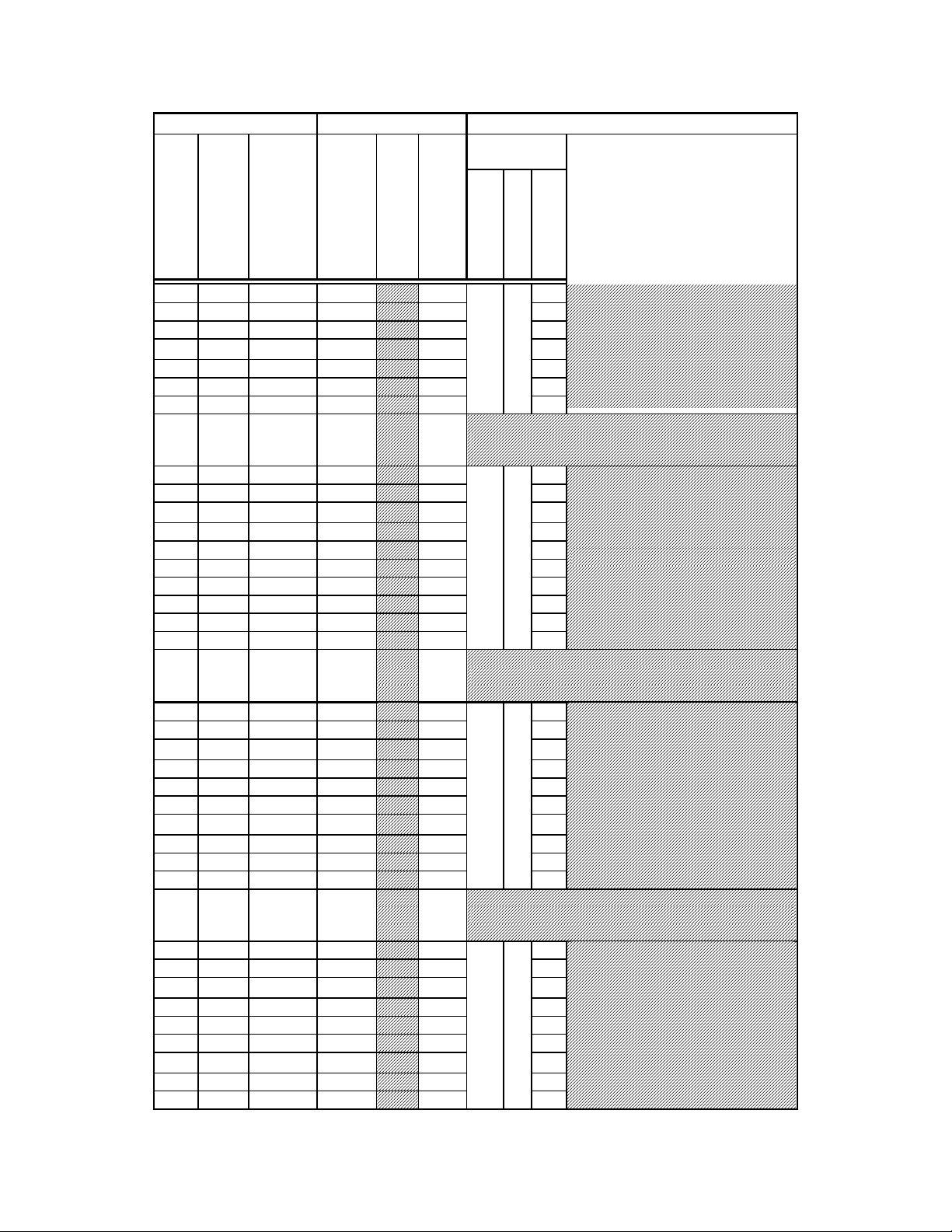
ASCII
ASCII ASCII
ASCII
Command Byte Value
Command Byte Value Keyboard Entry
Command Byte ValueCommand Byte Value
Dec.
Dec.
Dec.Dec.
Hex.
Hex. Binary
Hex.Hex.
Binary Alt
BinaryBinary
99 63 01010011
100 64 01010100
101 65 01010101
102 66 01010110
103 67 01010111
104 68 01011000
105 69 01011001
106
111
6A
01011010
-
-
6F
-
01011111
112 70 01110000
113 71 01110001
114 72 01110010
115 73 01110011
116 74 01110100
117 75 01110101
118 76 01110110
119 77 01110111
120 78 01111000
121 79 01111001
122
127
7A
01111010
-
–
7F
-
01111111
128 80 10000000
129 81 10000001
130 82 10000010
131 83 10000011
132 84 10000100
133 85 10000101
134 86 10000110
135 87 10000111
136 88 10001000
137 89 10001001
138
143
8A
10001010
-
-
8F
-
10001111
144 90 10010000
145 91 10010001
146 92 10010010
147 93 10010011
148 94 10010100
149 95 10010101
150 96 10010110
151 97 10010111
152 98 10011000
Keyboard Entry Description
Keyboard EntryKeyboard Entry
Alt----
AltAlt
keypad
keypad
keypad keypad
entry
entry
entryentry
Alt-0099
Alt-0100
Alt-0101
Alt-0102
Alt-0103
Alt-0104
Alt-0105
Alt-0106
Alt-0111
Alt-0112
Alt-0113
Alt-0114
Alt-0115
Alt-0116
Alt-0117
Alt-0118
Alt-0119
Alt-0120
Alt-0121
Alt-0122
Alt-0127
Alt-0128
Alt-0129
Alt-0130
Alt-0131
Alt-0132
Alt-0133
Alt-0134
Alt-0135
Alt-0136
Alt-0137
Alt-0138
Alt-0143
Alt-0144
Alt-0145
Alt-0146
Alt-0147
Alt-0148
Alt-0149
Alt-0150
Alt-0151
Alt-0152
Ctr
Ctrllll----
CtrCtr
char.
char.
char.char.
–
–
-
Filter Wheel
Filter Wheel
Filter Wheel Filter Wheel
Command
def./
def./----
def./def./
char.
char.
char.char.
Command
CommandCommand
WWWW
SSSS
hhhh
pppp
eeee
eeee
eeee
eeee
llll
dddd
c 3
d 4
e 5
f 6
g 7
h 8
i 9
j
– o
p 0
q 1
r 2
s 3
t 4
u 5
A 7
v 6
w 7
x 8
y
z
–
(DEL)
0
1
2
3
4
5
B 0
6
7
8
0
B 1
1
2
3
4
5
6
7
55
Description
DescriptionDescription
Shutter or
Shutter or
Shutter orShutter or
Special Command
Special Command
Special CommandSpecial Command
FFFF
iiii
llll
tttt
eeee
rrrr
9
9
8
LAMBDA 10-2 OPERATION MANUAL – REV. 2.04 (20120224)
Page 64

56
ASCII
ASCII ASCII
ASCII
Command Byte Value
Command Byte Value Keyboard Entry
Command Byte ValueCommand Byte Value
Dec.
Dec.
Dec.Dec.
Hex.
Hex. Binary
Hex.Hex.
Binary Alt
BinaryBinary
153 99 10011001
154
159
9A
10011010
-
-
9F
-
10011111
160 A0 10100000
161 A1 10100001
162 A2 10100010
163 A3 10100011
164 A4 10100100
165 A5 10100101
166 A6 10100110
167 A7 10100111
168 A8 10101000
169 A9 10101001
170 AA 10101010
171 AB 10101011
172 AC 10101100
185
175
AD
10101101
-
-
AF
-
10101111
176 B0 10110000
177 B1 10110001
178 B2 10110010
179 B3 10110011
180 B4 10110100
181 B5 10110101
182 B6 10110110
183 B7 10110111
184 B8 10111000
185 B9 10111001
186 BA 10111010
187 BB 10111011
188 BC 10111100
189
191
BD
10111101
-
-
BF
-
10111111
192 C0 11000000
193 C1 11000001
194 C2 11000010
195 C3 11000011
196 C4 11000100
197 C5 11000101
198 C6 11000110
199 C7 11000111
200 C8 11001000
Keyboard Entry Description
Keyboard EntryKeyboard Entry
Alt----
AltAlt
keypad
keypad
keypad keypad
entry
entry
entryentry
Alt-0153
Alt-0154
Alt-0159
Alt-0160
Alt-0161
Alt-0162
Alt-0163
Alt-0164
Alt-0165
Alt-0166
Alt-0167
Alt-0168
Alt-0169
Alt-0170
Alt-0171
Alt-0172
Alt-0185
Alt-0175
Alt-0176
Alt-0177
Alt-0178
Alt-0179
Alt-0180
Alt-0181
Alt-0182
Alt-0183
Alt-0184
Alt-0185
Alt-0186
Alt-0187
Alt-0188
Alt-0189
Alt-0191
Alt-0192
Alt-0193
Alt-0194
Alt-0195
Alt-0196
Alt-0197
Alt-0198
Alt-0199
Alt-0200
Ctr
Ctrllll----
CtrCtr
char.
char.
char.char.
-
-
-
Description
DescriptionDescription
Filter Wheel
def./
def./----
def./def./
char.
char.
char.char.
Filter Wheel
Filter Wheel Filter Wheel
Command
Command
CommandCommand
WWWW
SSSS
FFFF
hhhh
pppp
iiii
eeee
eeee
llll
eeee
eeee
tttt
llll
dddd
eeee
Shutter or
Shutter or
Shutter orShutter or
Special Command
Special Command
Special CommandSpecial Command
rrrr
9
0
1
2
3
4
5
B 2
6
7
8
9
Open Shutter A
Open Shutter A conditionally
Close Shutter A
0
1
2
3
4
5
B 3
6
7
8
9
Open Shutter B
Open Shutter B conditionally
Close Shutter B
0
B 4
1
2
3
4
5
6
7
8
LAMBDA 10-2 OPERATION MANUAL – REV. 2.04 (20120224)
Page 65

ASCII
ASCII ASCII
ASCII
Command Byte Value
Command Byte Value Keyboard Entry
Command Byte ValueCommand Byte Value
Dec.
Dec.
Dec.Dec.
Hex.
Hex. Binary
Hex.Hex.
Binary Alt
BinaryBinary
201 C9 11001001
202
207
CA
11001010
-
-
CF
-
11001111
208 D0 11000000
209 D1 11000001
210 D2 11000010
211 D3 11000011
212 D4 11000100
213 D5 11000101
214 D6 11000110
215 D7 11000111
216 D8 11001000
217 D9 11001001
218
222
DA
11001010
-
-
DE
-
11001110
223 DF 11011111
224 E0 11010000
225 E1 11010001
226 E2 11010010
227 E3 11010011
228 E4 11010100
229 E5 11010101
230 E6 11010110
231 E7 11010111
232 E8 11011000
233 E9 11011001
234
237
EA
11011010
-
-
ED
-
11011101
238 EE 11011110
239 EF 11011111
240 F0 11110000
241 F1 11110001
242 F2 11110010
243 F3 11110011
244 F4 11110100
245 F5 11110101
246 F6 11110110
247 F7 11110111
248 F8 11111000
249 F9 11111001
Keyboard Entry Description
Keyboard EntryKeyboard Entry
Alt----
AltAlt
keypad
keypad
keypad keypad
entry
entry
entryentry
Alt-0201
Alt-0202
Alt-0207
Alt-0208
Alt-0209
Alt-0210
Alt-0211
Alt-0212
Alt-0213
Alt-0214
Alt-0215
Alt-0216
Alt-0217
Alt-0218
Alt-0222
Alt-0223
Alt-0224
Alt-0225
Alt-0226
Alt-0227
Alt-0228
Alt-0229
Alt-0230
Alt-0231
Alt-0232
Alt-0233
Alt-0234
Alt-0237
Alt-0238
Alt-0239
Alt-0240
Alt-0241
Alt-0242
Alt-0243
Alt-0244
Alt-0245
Alt-0246
Alt-0247
Alt-0248
Alt-0249
Ctr
Ctrllll----
CtrCtr
char.
char.
char.char.
-
-
-
Description
DescriptionDescription
Filter Wheel
Filter Wheel
Filter Wheel Filter Wheel
Command
def./
def./----
def./def./
char.
char.
char.char.
Command
CommandCommand
WWWW
SSSS
hhhh
pppp
eeee
eeee
eeee
eeee
llll
dddd
FFFF
iiii
llll
tttt
eeee
rrrr
9
0
1
2
3
4
5
B 5
6
7
8
9
Batch Transfer of next 4 bytes (2
shutter and 2 filter wheel
commands)
0
1
2
3
4
5
B 6
6
7
8
9
On Line
0
1
2
3
4
5
B 7
6
7
8
9
Shutter or
Shutter or
Shutter orShutter or
Special Command
Special Command
Special CommandSpecial Command
57
LAMBDA 10-2 OPERATION MANUAL – REV. 2.04 (20120224)
Page 66

58
ASCII
ASCII ASCII
ASCII
Command Byte Value
Command Byte Value Keyboard Entry
Command Byte ValueCommand Byte Value
Dec.
Dec.
Dec.Dec.
Hex.
Hex. Binary
Hex.Hex.
250
255
FA
FF
NOTE 1:
NOTE 1: All filter wheel command bytes are encoded with three commands:
NOTE 1:NOTE 1:
1. Wheel selection (Bit 7): 0 for Wheel A, 1 for Wheel B.
2. Speed (Bits 4 – 6): Contains value for speed (0 through 7).
3. Position (Bits 0 – 3): Contains value for position (0 through 9).
NOTE 2:
NOTE 2: The “ASCII def./char.” column for codes 128 through 255 (80 through FF hex) is left blank,
NOTE 2:NOTE 2:
since there are no ASCII character definitions for the codes in this range. However, many computers and
operating systems do support characters within this range, although there is no single standard across all
platforms. Furthermore, many operating systems, such as Microsoft Windows and Apple Mac OS X, have
several “code pages” (character sets), many of which are country/language specific, from which the user
can select. Therefore, this part of the table is left blank – if you wish, you may write in the characters
defined in the character set you use on a regular basis.
Binary Alt
BinaryBinary
11111010-
11111111
Keyboard Entry Description
Keyboard EntryKeyboard Entry
Filter Wheel
Alt----
AltAlt
keypad
keypad
keypad keypad
entry
entry
entryentry
Alt-0250
-
Alt-0255
Ctr
Ctrllll----
CtrCtr
char.
char.
def./
def./----
char.char.
def./def./
char.
char.
char.char.
Filter Wheel
Filter Wheel Filter Wheel
Command
Command
CommandCommand
WWWW
SSSS
FFFF
hhhh
pppp
iiii
eeee
eeee
llll
eeee
eeee
tttt
llll
dddd
eeee
rrrr
Description
DescriptionDescription
Special Command
Special Command
Special CommandSpecial Command
Shutter or
Shutter or
Shutter orShutter or
Table E-2. Filter command structure.
Functional Groups
Wheel
Group Bit #
Group Bit # 0000 2222 1111 0000 3333 2222 1111 0000
Group Bit #Group Bit #
Decimal Group Example Values
Decimal Group Example Values 0 5 7
Decimal Group Example ValuesDecimal Group Example Values
Binary Group Example Values
Binary Group Example Values 0 1 0 1 0 1 1 1
Binary Group Example ValuesBinary Group Example Values
Example Parallel Port Pin #
Example Parallel Port Pin # 9 8 7 6 5 4 3 2
Example Parallel Port Pin #Example Parallel Port Pin #
Wheel Speed
WheelWheel
Functional Groups
Functional GroupsFunctional Groups
Speed Filter Position
SpeedSpeed
Filter Position
Filter PositionFilter Position
Encoding filter wheel commands into a single byte:
If Wheel A: (0 * 128) + (
If Wheel B: (1 * 128) + (
speed
speed
* 16) +
* 16) +
position
position
= command byte
= command byte
LAMBDA 10-2 OPERATION MANUAL – REV. 2.04 (20120224)
Page 67

INDEX
59
AAAA
accessories ......................................................... 4, 51
adapters
specifications........................................................5
BBBB
back panel...............................................................21
batch transfer.........................................................35
serial interface....................................................45
blanking disc
blanking disc................................................... 14, 19
blanking discblanking disc
BUSY line
BUSY line...............................................................36
BUSY lineBUSY line
use of...................................................................37
CCCC
cleaning...................................................................47
commands
commands
commandscommands
batch....................................................................34
filter
filter ............................................................. 32, 33
filterfilter
shutter ................................................................34
special
special .......................................................... 32, 34
specialspecial
controller ................................................................21
cable specs ..........................................................56
operation.............................................................21
DDDD
dimensions
dimensions
dimensionsdimensions
controller
controller..................................................... 55, 56
controllercontroller
disclaimer ............................................................... iii
display.....................................................................23
initialization screen ...........................................12
initialization screen in local mode....................12
switching speeds ................................................26
filter cup....................................................................3
installation..........................................................18
loose.....................................................................18
filter holder
drop in...................................................................3
slide in...................................................................3
specifications........................................................4
filter loading port...................................................17
filter position
manual selection ................................................25
selection..............................................................25
filter position selection..........................................18
filter switching
speed values........................................................26
filter wheel................................................................2
adding ...................................................................2
connection ..........................................................22
cover plate.............................................................3
housing .................................................................3
installation..........................................................10
selection..............................................................25
front panel controls ...............................................23
fuse
holder..................................................................53
location........................................................... 8, 53
replacement................................................. 22, 53
spare....................................................................53
fuse replacement.................................................... iii
fuses, replacement
fuses, replacement
fuses, replacementfuses, replacement
internal ...............................................................55
mains
mains ............................................................ iii, 55
mainsmains
EEEE
electrical connections ..................................... 11, 21
error detection........................................................27
ERROR line
use of...................................................................38
ERROR
ERROR signal
ERRORERROR
signal .......................................................36
signal signal
errors in movement...............................................27
FFFF
filter
cup spacer ring...................................................15
holder..................................................................15
loading.......................................................... 13, 15
maximum thickness
maximum thickness..........................................14
maximum thicknessmaximum thickness
neutral density...................................................19
retaining ring.....................................................15
IIII
initialization screen...............................................12
initialization screen in local mode........................12
input commands
serial interface....................................................44
via printer port...................................................40
KKKK
keypad.....................................................................23
keys
F1,F2...................................................................23
LOCAL................................................................23
numeric...............................................................23
ON LINE............................................................23
SHUTR...............................................................23
SPEED................................................................23
specifications........................................................4
LAMBDA 10-2 OPERATION MANUAL – REV. 2.04 (20120224)
Page 68

60
LLLL
line power (mains)...................................................8
line voltage .............................................................22
loading port ..............................................................3
local control............................................................24
local mode...............................................................12
MMMM
mains
mains ........................................................................8
mainsmains
fuses
fuses..............................................................iii, 55
fusesfuses
power consumption ...........................................55
power cord..........................................................55
voltage
voltage.................................................................55
voltagevoltage
maintenance...........................................................47
manual control.......................................................24
MANUAL mode.....................................................25
mechanical description............................................2
motor.........................................................................3
mounting
vibrations..............................................................7
mounting ears..........................................................3
NNNN
notes
user............................................................... 65, 66
OOOO
operation
vibrations..............................................................7
optical port................................................................3
output commands
serial interface....................................................46
via printer port...................................................41
PPPP
packaging..................................................................7
parallel interface
connection ..........................................................31
output lines.........................................................36
PC pin assignments...........................................39
PC printer ports.................................................38
pin assignments.................................................31
strategies.............................................................37
WAIT ..................................................................41
parallel port
connection ..........................................................22
input commands ................................................32
power
connection ..........................................................22
consumption.......................................................55
voltage selector...................................................22
power cord
mains...................................................................55
power entry module...............................................53
power switch ............................................................9
power up sequence.................................................24
precautions............................................................. iii
electrical.............................................................. iii
RRRR
rear panel
connectors...........................................................22
remote control
parallel port........................................................31
serial port............................................................43
RESET....................................................................23
retaining ring
retaining ring.........................................................14
retaining ringretaining ring
SSSS
safety warnings...................................................... iii
electrical.............................................................. iii
safety considerations with high-intensity light
sources .............................................................iv
safety wa
safety warnings & precautions
safety wasafety wa
operational
operational..........................................................iv
operationaloperational
rnings & precautions
rnings & precautionsrnings & precautions
safety warnings & precautions........................ iii, iv
serial interface........................................................43
parameters..........................................................44
pin assignments.................................................44
serial port
connection ..........................................................22
setting up..................................................................1
shutter
adding ...................................................................5
housing .................................................................3
shutter control
local (keypad) .....................................................26
TTL line..............................................................42
spacer ring
spacer ring..............................................................14
spacer ringspacer ring
spanner wrench .....................................................15
speed
manual selection ................................................25
values..................................................................26
speed setting...........................................................13
start-up ...................................................................12
stepper motors .........................................................5
support base ...........................................................11
support base clamps ..............................................11
support rods ...........................................................11
TTTT
technical specifications..........................................55
controller
controller............................................................55
controllercontroller
dimensions
dimensions .............................................. 55, 56
dimensionsdimensions
technical support .....................................................1
TTL lines................................................................42
LAMBDA 10-2 OPERATION MANUAL – REV. 2.04 (20120224)
Page 69

UUUU
unpacking.................................................................7
VVVV
vacuum fluorescent display...................................23
vibration ...................................................................7
NOTES
NOTES
NOTESNOTES
voltage
voltage
voltagevoltage
mains
mains ..................................................................55
mainsmains
voltage selector switch.............................................9
WWWW
warranty.................................................................49
weight
weight .............................................................. 55, 56
weightweight
61
LAMBDA 10-2 OPERATION MANUAL – REV. 2.04 (20120224)
Page 70

62
NOTES
NOTES
NOTESNOTES
LAMBDA 10-2 OPERATION MANUAL – REV. 2.04 (20120224)
 Loading...