

Page 1
dPatch
®
DIGITAL PATCH CLAMP AMPLIFIER SYSTEM
with
®
SutterPatch
DATA ACQUISITION, MANAGEMENT AND ANALYSIS SOFTWARE
QUICK START GUIDE
Page 2
QUICK START GUIDE dPATCH
®
/ dPATCH-2
DIGITAL PATCH CLAMP AMPLIFIER SYSTEMS OVERVIEW
Please read these instructions carefully before installation. This guide covers both the
dPatch® and dPatch-2 systems. If you have any questions or need additional information,
contact Sutter Instrument.
OPERATING SYSTEM REQUIREMENTS
Windows 7 or later: 64-bit versions
Mac OS 10.11 (El Capitan) or later
INSTALL HARDWARE
1. Attach dPatch headstage(s) to amplifier front panel: HEADSTAGE 1 & 2. dPatch
headstages can be attached to any headstage port; they are not “matched” to a port.
2. OPTIONAL: Attach dPatch Screw Terminal Board or dPatch Expansion Panel to
amplifier rear panel: DIGITAL OUTPUTS.
3. Attach USB 3 cable to USB 3 port on amplifier rear panel and your computer. The
connector on the dPatch rear panel must click in place.
4. Attach power cord to amplifier rear panel and a grounded power outlet.
INSTALL IGOR PRO/SUTTERPATCH SOFTWARE
1. Power on computer.
2. If you have Internet access, download the latest version of the SutterPatch Software
installer from www.sutter.com/AMPLIFIERS/SutterPatch.html
3. If Internet access is not available, attach the included USB flash drive to your
computer.
4. Double click on ‘SutterPatch_Installer_with_Igor’ (Windows) or
‘sutterpatch_mac_full’ (Mac OS).
5. Follow the installer prompts for current Igor software.
6. Open Igor Pro and activate the Igor Pro license as instructed:
i. Serial Number:
ii. Activation Key:
affix label here
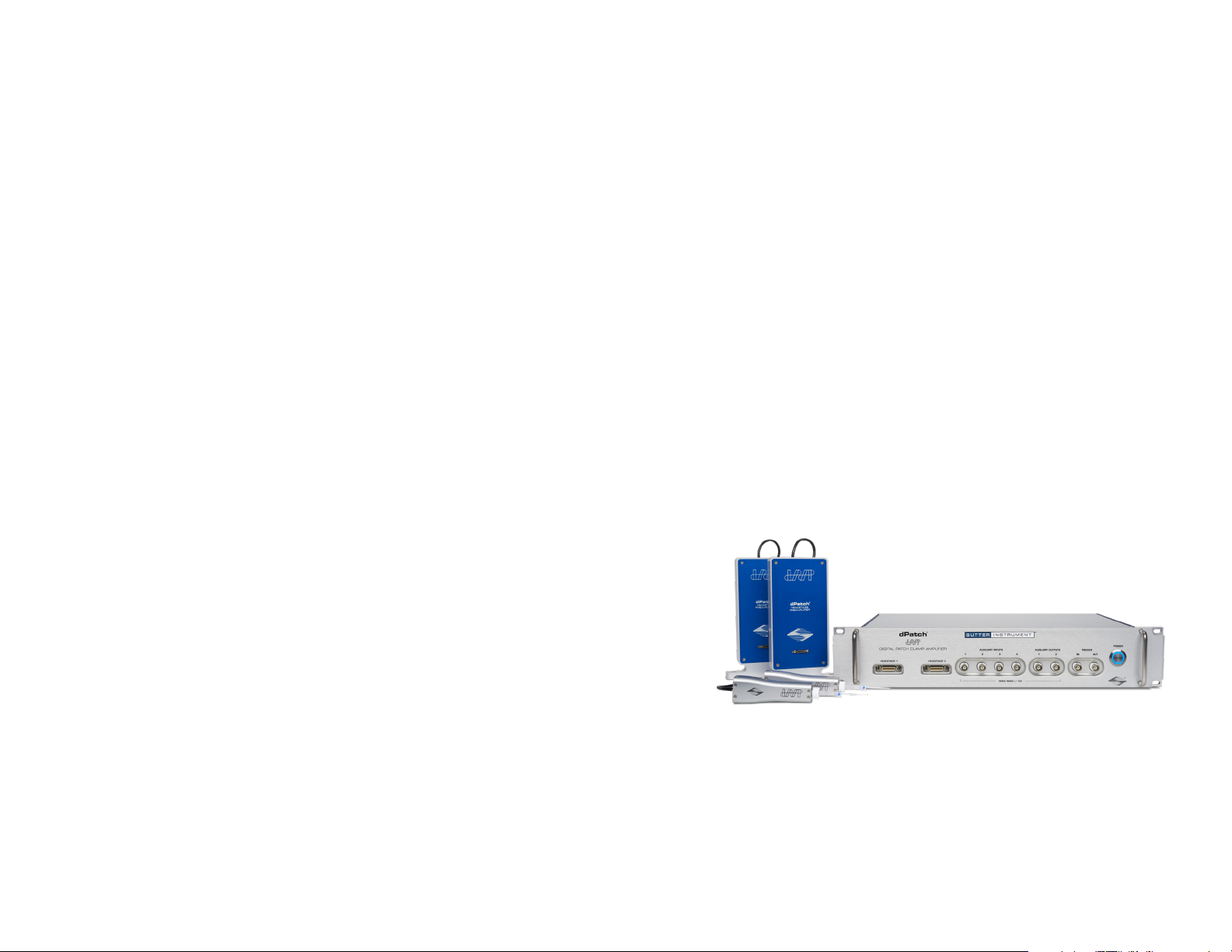
4. On dashboard window:
I. Click on the Acquire Data icon:
Acquire Data
II. Click on the Membrane Test icon:
Membrane Test
5. Scope + Analysis windows open:
(Actual analysis values depend on dPatch filter settings)
I. With the Model Cell switch in Bath position, click the Bath button.
Pipette Resistance = ~10 MΩ
II. With the Model Cell switch in Seal position, click the Seal button.
Seal Resistance > 10,000 MΩ
III. With the Model Cell switch in Cell position, click the Cell button.
Access Resistance = ~10 MΩ
Membrane Resistance = ~500 MΩ
Membrane Capacitance = ~28 pF
Move the Model Cell and shielding to HEADSTAGE 2 (if installed), set the Scope
window to ‘Headstage 2’, and repeat steps I – III.
TEST SYSTEM
1. Model Cell:
a. Attach Model Cell to HEADSTAGE 1 and tighten the collar.
b. Attach ground wire to HEADSTAGE 1 and Model Cell (gold plugs).
c. Surround with aluminum foil shielding and ground it to the headstage
ground connector.
2. Click icon to launch Igor:
3. SutterPatch welcome screen will open. Press ‘Start’.
SUTTER INSTRUMENT
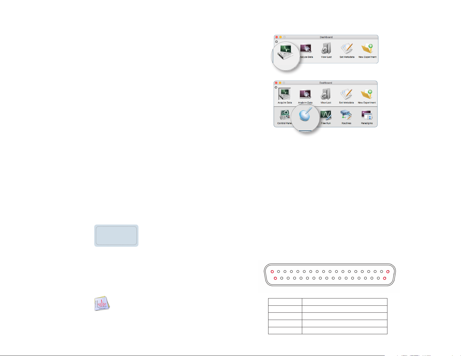
BACK PANEL
DIGITAL OUTPUTS 1-16
19 1
37 20
DIGITAL OUTPUTS PINOUT
PIN FUNCTION
1 - 16 Digital Output 1 - 16
17 - 19 +5 V
20 - 35 Ground
36 - 37 +5 V
DIGITAL PATCH CLAMP AMPLIFIER SYSTEM
 Loading...