

Page 1

OPERATION MANUAL
Rev. 2.14 ( 20081107)
Lambda DG
Lambda DG----4
Lambda DGLambda DG
Lambda DG
Lambda DG----5
Lambda DGLambda DG
Ultra
Ultra----High
UltraUltra
Wavelength Switching
Wavelength Switching
Wavelength SwitchingWavelength Switching
Systems
Systems
SystemsSystems
and
and
andand
High----Speed
HighHigh
Speed
SpeedSpeed
4
44
5
55
Page 2

Page 3
Lambda DG
Lambda DG----4 and Lambda DG
Lambda DGLambda DG
4 and Lambda DG----5555
4 and Lambda DG4 and Lambda DG
Ultra-High-Speed Wavelength Switching
Systems
Operation Manual
(Rev. 2.14 (20081107))
Sutter Instrument Company
One Digital Drive
Novato, CA 94949
Voice: 415-883-0128 Web: www.sutter.com
Fax: 415-883-0572 Email: info@sutter.com
Page 4

II
Copyright © 2008 Sutter Instrument Company. All Rights Reserved.
LAMBDA 10 ® is a registered trademark, and
Sutter Instrument Company.
Smart
Shutter™ is a trademark, both of
LAMBDA DG-4 & DG-5 OPERATION MANUAL – REV. 2.14 (20081107)
Page 5

TABLE OF CONTENTS
TABLE OF CONTENTS
TABLE OF CONTENTSTABLE OF CONTENTS
1. GENERAL INFORMATI
1. GENERAL INFORMATION
1. GENERAL INFORMATI1. GENERAL INFORMATI
1.1 A
BOUT THIS MANUAL
1.2 L
AMBDA
1.3 U
NPACKING
2. SAFETY WARNINGS
2. SAFETY WARNINGS ................................
2. SAFETY WARNINGS2. SAFETY WARNINGS
DG-4
AND LAMBDA
...................................................................................................................................... 1
ON ................................
................................................................
ONON
................................................................
......................................................................................................................1
DG-5.................................................................................................1
................................................................
................................................................
................................................................
................................................................
................................................................
................................................................
...................................................
................................................................
........................................
................................................................
........ 1111
................
................... 3333
......................................
III
2.1 TO F
3. MAKE IT GLOW
3. MAKE IT GLOW................................
3. MAKE IT GLOW3. MAKE IT GLOW
3.1 S
3.2 G
4. OPTICAL PATHWAY
4. OPTICAL PATHWAY ................................
4. OPTICAL PATHWAY4. OPTICAL PATHWAY
4.1 L
URTHER AVOID ELECTRICAL SHOCK
................................................................
................................................................
OME BASIC INFORMATION
ETTING STARTED
IGHT GUIDE
..........................................................................................................................6
................................................................
................................................................
& O
PTICAL HOLDER INSTALLATION
.............................................................................................................5
: ....................................................................................3
................................................................
................................................................
................................................................
................................................................
............................................................
................................................................
...................................................
................................................................
......................................................................9
............................ 5555
........................................................
................... 9999
......................................
4.1.1 Liquid Light Guide...................................................................................................................9
4.1.2 Liquid Light Guide Installation .............................................................................................9
4.1.3 Optical Holder........................................................................................................................10
4.2 L
OADING FILTERS
..........................................................................................................................10
4.2.1 Filter Orientation...................................................................................................................10
4.2.2 Loading Filters .......................................................................................................................11
4.2.3 Selection of a Filter Position.................................................................................................12
4.2.4 Blanking Discs........................................................................................................................12
4.2.5 Neutral Density Filters .........................................................................................................12
4.2.6 Filter Holder Installation......................................................................................................13
5. CONTROLLER
5. CONTROLLER ................................
5. CONTROLLER5. CONTROLLER
5.1 C
ONTROL ELECTRONICS
5.2 P
OWER-UP SEQUENCE
5.3 T
OP PANEL CONTROLS
................................................................
................................................................
...............................................................................................................15
...................................................................................................................15
.................................................................................................................16
................................................................
................................................................
............................................................
................................................................
............................ 15
........................................................
5.3.1 Keypad.....................................................................................................................................16
5.4 E
LECTRICAL CONNECTIONS
.........................................................................................................16
5.4.1 Parallel Port............................................................................................................................17
5.4.2 Serial Port...............................................................................................................................17
5.4.3 Filter Value Out.....................................................................................................................17
5.4.4 Sync..........................................................................................................................................18
5.4.5 DAC..........................................................................................................................................18
5.4.6 Strobe ......................................................................................................................................18
5.4.7 Line Power..............................................................................................................................18
5.5 F
USE
...............................................................................................................................................18
5.6 M
ODES OF OPERATION
(LOCAL).................................................................................................19
5.6.1 General Information..............................................................................................................19
5.6.2 Selecting an Operational Mode: The MODE Key..............................................................20
5.6.3 Move on Command Mode......................................................................................................21
5.6.4 Move on Sync Pulse Mode.....................................................................................................23
15
1515
LAMBDA DG-4 & DG-5 OPERATION MANUAL – REV. 2.14 (20081107)
Page 6

IV
5.6.5 Move on Strobe Pulse Mode..................................................................................................24
5.6.6 Move on Sync, Inhibited by the Strobe Line Mode............................................................25
5.6.7 Edit a Filter Definition Mode ...............................................................................................27
5.6.7.1 General Information .................................................................................................................................................27
5.6.7.2 Filter Numbers...........................................................................................................................................................28
5.6.7.3 Attenuation.................................................................................................................................................................28
5.6.7.4 Programming a Filter Number (“Logical Filter”)\..............................................................................................29
5.6.7.5 Manual Adjustment of Attenuation .......................................................................................................................30
5.6.8 Setup Ring Buffer Mode........................................................................................................33
5.6.8.1 General Information .................................................................................................................................................33
5.6.8.2 Storing the FILTER NUMBER Sequence ............................................................................................................33
5.6.8.3 Viewing an Existing FILTER NUMBER Sequence ............................................................................................34
5.6.8.4 Running the RING BUFFER Sequence................................................................................................................35
5.6.9 Turbo-Blanking Mode ...........................................................................................................37
5.6.10 Display the First Four Filter Values Mode.......................................................................38
6. REMOTE INTERFACE
6. REMOTE INTERFACE ................................
6. REMOTE INTERFACE6. REMOTE INTERFACE
6.1 P
ARALLEL INTERFACE
................................................................
................................................................
...................................................................................................................39
................................................................
................................................................
..............................................
................................................................
.............. 39
............................
6.1.1 Connecting to the Lambda DG-4 parallel port...................................................................39
6.1.2 Input Lines..............................................................................................................................40
6.1.3 Command Codes.....................................................................................................................40
6.1.4 Busy Line ................................................................................................................................43
6.1.5 Interface Modes......................................................................................................................43
6.1.6 Controlling the Lambda DG-4 from a Computer’s Parallel (Printer) Port....................44
6.1.7 Reading the Status of the Lambda DG-4 ............................................................................46
6.1.8 Shutter Control ......................................................................................................................47
6.2 S
ERIAL INTERFACE
........................................................................................................................48
6.2.1 Connecting to the Lambda DG-4 Serial Input ...................................................................48
6.2.2 Controlling the Lambda DG-4 from a Computer’s Serial Port........................................49
6.2.3 Serial Port Command Echo ..................................................................................................50
6.2.4 Serial Port Command Completion Indicator......................................................................50
6.2.5 Reading the Status of the Lambda DG-4 ............................................................................50
39
3939
AAAAPPENDIX A. FUSE REPL
PPENDIX A. FUSE REPLACEMENT
PPENDIX A. FUSE REPLPPENDIX A. FUSE REPL
APPENDIX B. LIMITED
APPENDIX B. LIMITED WARRANTY
APPENDIX B. LIMITED APPENDIX B. LIMITED
APPENDIX C. DISCLAIM
APPENDIX C. DISCLAIMER
APPENDIX C. DISCLAIMAPPENDIX C. DISCLAIM
APPENDIX D. TECHNICA
APPENDIX D. TECHNICAL SPECIFICATIONS
APPENDIX D. TECHNICAAPPENDIX D. TECHNICA
APPENDI
APPENDIX E. REMOTE
APPENDIAPPENDI
TABLE OF FIGURES
TABLE OF FIGURES
TABLE OF FIGURESTABLE OF FIGURES
Figure 3-1. Lambda DG-4 optical pathway. ...........................................................................................5
Figure 3-2. Light guide installation..........................................................................................................6
X E. REMOTE----CONTROL
X E. REMOTEX E. REMOTE
ACEMENT ................................
ACEMENTACEMENT
WARRANTY ................................
WARRANTYWARRANTY
ER ................................
................................................................
ERER
................................................................
L SPECIFICATIONS................................
L SPECIFICATIONSL SPECIFICATIONS
CONTROL COMMAND REFERENCE
CONTROL CONTROL
LAMBDA DG-4 & DG-5 OPERATION MANUAL – REV. 2.14 (20081107)
................................................................
................................................................
................................................................
................................................................
................................................................
................................................................
................................................................
................................................................
COMMAND REFERENCE................................
COMMAND REFERENCECOMMAND REFERENCE
.......................................................
................................................................
........................................................
................................................................
........................................
................................................................
.......................................
................................................................
............................................
................................................................
.......................53
..............................................
........................55
................................................
............61
........................
53
5353
55
5555
........ 57
57
................
5757
....... 59
59
..............
5959
61
6161
Page 7

V
Figure 3-3. Lambda DG-4 left side. .........................................................................................................7
Figure 4-1. Liquid light guide installation..............................................................................................9
Figure 4-2. Light guide optical holder...................................................................................................10
Figure 4-3. Filter holder assembly.........................................................................................................11
Figure 4-4. Filter holder assembly with blanking disc........................................................................11
Figure 4-5. Lambda DG-4 left side. .......................................................................................................13
Figure 5-1. Keypad (top panel). .............................................................................................................16
Figure 5-2. Electrical connections (rear panel)....................................................................................17
Figure 5-3. Filter value out connector...................................................................................................18
Figure 5-4. Optical pathway based on filter position. .........................................................................27
Figure 5-5. DG-4 output attenuation....................................................................................................28
Figure 5-6. Log of attenuation vs. change in output galvanometer value. .......................................29
Figure 6-1. Parallel port DB25 connector (male).................................................................................39
Figure 6-2. DB25 Parallel connector.....................................................................................................45
Figure 6-3. Serial control connections (viewed from rear of cabinet). ..............................................48
Figure A-1. Fuse replacement................................................................................................................53
TABLE OF TABLES
TABLE OF TABLES
TABLE OF TABLESTABLE OF TABLES
Table 5-1. Input and output galvanometer values based on filter position......................................27
Table 6-1. Parallel port pin assignments..............................................................................................39
Table 6-2. Command code types. ...........................................................................................................40
Table 6-3. Controller commands............................................................................................................41
Table 6-4. Parallel port pin connections and definitions....................................................................45
Table 6-5. Parallel port numbering and addressing............................................................................46
Table 6-6. Shutter open and close commands......................................................................................48
LAMBDA DG-4 & DG-5 OPERATION MANUAL – REV. 2.14 (20081107)
Page 8

VI
TableA-1. Mains fuse requirements according to lamp power ratings and line voltage.................54
Table D-1. Cable specifications...............................................................................................................60
Table E-1. Remote-control filter selection command reference..........................................................61
Table E-2. Filter selection command structure. ...................................................................................62
Table E-3. Remote-control special commands reference.....................................................................62
LAMBDA DG-4 & DG-5 OPERATION MANUAL – REV. 2.14 (20081107)
Page 9

1.
1. G ENER AL INFO RMA TION
GEN ERAL IN FOR M ATI ON
1.1.
GEN ERAL IN FOR M ATI ONGEN ERAL IN FOR M ATI ON
1.1
1.1 About this Manual
About this Manual
1.11.1
About this ManualAbout this Manual
The Lambda DG-4 is an illumination system designed for rapid change of wavelength and
comprises three subsystems: controller, optical path and 175-Watt Xenon arc lamp with
power supply. All three subsystems are conveniently housed in one cabinet. For the most
part this manual is organized around those subsystems to provide you with ready access to
information, as you need it. Separate documentation for the lamp and its power supply
(provided by PerkinElmer Optoelectronics) accompanies this manual.
In the next few pages you will find information on the safe use of this device, unpacking
instructions and quick-start (“Make it Glow”) directions to help you get acquainted with the
operation of the Lambda DG-4 (using the manual mode). Please take the time to read these
instructions to assure the safe and proper use of this instrument.
This manual is currently under construction. If there are any areas that you feel should be
covered in greater detail we would like to hear from you. Please contact our Technical
Support staff with your suggestions (415-883-0128 or info@sutter.com).
1
1.2
1.2 Lambda DG
Lambda DG----4 and Lambda DG
1.21.2
Lambda DGLambda DG
4 and Lambda DG----5555
4 and Lambda DG4 and Lambda DG
Throughout this manual, unless otherwise noted, all references and descriptions pertaining
to “Lambda DG-4” (or just “DG-4”) apply equally to the Lambda DG-5. The only difference
between the Lambda DG-4 and Lambda DG-5 is the set of light interference filters, as
follows:
• The Lambda DG-4 filter set consists of four 25mm (1-inch) diameter filters.
• The Lambda DG-5 filter set consists of three 18mm and two 25mm (1-inch) diameter
filters.
Both models of the Lambda DG series are calibrated at the factory according to each one’s
filter set arrangement.
1.3
1.3 Unpacking
Unpacking
1.31.3
UnpackingUnpacking
The Lambda DG-4 and associated hardware comes packed in a single carton. The following
is a list of the components found there. If you believe that any of these components are
missing or show obvious signs of damage from shipping, please contact the factory.
Parallel Interface Cable
Serial Interface Cable
Power Cord
4 Individual Filter holders with retaining rings, spacer rings and blanking discs
Neutral Density holder retaining ring, spacer ring and blanking disc
Spanner Wrench
Liquid Light Guide
Manual
Microscope adapters (if ordered)
LAMBDA DG-4 & DG-5 OPERATION MANUAL – REV. 2.14 (20081107)
Page 10

2
LAMBDA DG-4 & DG-5 OPERATION MANUAL – REV. 2.14 (20081107)
Page 11

3
2.
2. S A FET Y W A RNI NGS
SAF ETY WAR NIN GS
2.2.
SAF ETY WAR NIN GSS AFET Y W ARN I NGS
Replace fuse only with the same type
Replace fuse only with the same type::::
Replace fuse only with the same type Replace fuse only with the same type
5 x 20 mm glass tube
5 x 20 mm glass tube
5 x 20 mm glass tube5 x 20 mm glass tube
TTTTime delay
ime delay (medium)
ime delayime delay
RRRRating:
ating:
ating:ating:
If this instrument is equipped with
If this instrument is equipped with a
If this instrument is equipped with If this instrument is equipped with
삟 100
삟 220
If this instrument is equipped with a
If this instrument is equipped with a 300
If this instrument is equipped with a If this instrument is equipped with a
삟 100
삟 220
A spare fuse is provided, being located in the power input module. Please refer to
A spare fuse is provided, being located in the power input module. Please refer to
A spare fuse is provided, being located in the power input module. Please refer to A spare fuse is provided, being located in the power input module. Please refer to
Appendix A
Appendix A:
Appendix AAppendix A
instructions on ho
instructions on how to change the fuse.
instructions on hoinstructions on ho
(medium),
(medium) (medium)
100 –––– 120 VAC Operation: 4.0A, 125V fuse; or
120 VAC Operation: 4.0A, 125V fuse; or
100 100
120 VAC Operation: 4.0A, 125V fuse; or 120 VAC Operation: 4.0A, 125V fuse; or
220 –––– 240 VAC Operation: T3.15A, 250V fuse.
240 VAC Operation: T3.15A, 250V fuse.
220 220
240 VAC Operation: T3.15A, 250V fuse. 240 VAC Operation: T3.15A, 250V fuse.
100 –––– 120 VAC Operation: 5.0A, 125V fuse, or
120 VAC Operation: 5.0A, 125V fuse, or
100 100
120 VAC Operation: 5.0A, 125V fuse, or 120 VAC Operation: 5.0A, 125V fuse, or
220 –––– 240 VAC Operation: T
240 VAC Operation: T3.15A, 250V fuse.
220 220
240 VAC Operation: T 240 VAC Operation: T
: FUSE
FUSE REPLACEMENT
: :
FUSEFUSE
w to change the fuse.
w to change the fuse.w to change the fuse.
, time lag
time lag,,,, or
, ,
time lagtime lag
REPLACEMENT for more details on fuse ratings and for
REPLACEMENTREPLACEMENT
or ““““slow blow
slow blow””””))))
or or
slow blowslow blow
a 175
175----Watt lamp
a a
3.15A, 250V fuse.
3.15A, 250V fuse.3.15A, 250V fuse.
for more details on fuse ratings and for
for more details on fuse ratings and for for more details on fuse ratings and for
Watt lamp, replace with
175175
Watt lampWatt lamp
300----Watt lamp
Watt lamp, replace with
300300
Watt lampWatt lamp
, replace with
, replace with, replace with
, replace with
, replace with, replace with
Infrared Radiation: The infrared radiation (and ultraviolet radiation) generated by
Infrared Radiation: The infrared radiation (and ultraviolet radiation) generated by
Infrared Radiation: The infrared radiation (and ultraviolet radiation) generated by Infrared Radiation: The infrared radiation (and ultraviolet radiation) generated by
this lamp can cause significant skin burns and eye damage.
this lamp can cause significant skin burns and eye damage.
this lamp can cause significant skin burns and eye damage.this lamp can cause significant skin burns and eye damage.
Explosion: High internal pressure
Explosion: High internal pressure exists in any xenon arc lamp.
Explosion: High internal pressureExplosion: High internal pressure
High Voltage: High ignition voltages, which exist inside the cabinet, can be lethal.
High Voltage: High ignition voltages, which exist inside the cabinet, can be lethal.
High Voltage: High ignition voltages, which exist inside the cabinet, can be lethal.High Voltage: High ignition voltages, which exist inside the cabinet, can be lethal.
Ozone: Because the UV
Ozone: Because the UV----enhanced version of the lamp generates significant ozone, it
Ozone: Because the UVOzone: Because the UV
must be used in a well
must be used in a well----ventilated environment. For mos
must be used in a wellmust be used in a well
requirement to ventilate the ozone
requirement to ventilate the ozone----free lamp.
requirement to ventilate the ozonerequirement to ventilate the ozone
2.1
2.1 To Further Avoid Electrical Shock
To Further Avoid Electrical Shock and Fire
2.12.1
To Further Avoid Electrical ShockTo Further Avoid Electrical Shock
Always use the grounded power supply cord set provided to connect the unit to a
Always use the grounded power supply cord set provided to connect the unit to a
Always use the grounded power supply cord set provided to connect the unit to a Always use the grounded power supply cord set provided to connect the unit to a
grounded outlet (3
grounded outlet (3----prong). This is required to protect you from injury i
grounded outlet (3grounded outlet (3
an electrical hazard occurs.
an electrical hazard occurs.
an electrical hazard occurs.an electrical hazard occurs.
Do not disassemble the unit. The only user serviceable parts are the line fuse, the
Do not disassemble the unit. The only user serviceable parts are the line fuse, the
Do not disassemble the unit. The only user serviceable parts are the line fuse, the Do not disassemble the unit. The only user serviceable parts are the line fuse, the
xenon bulb, and filters. The line fuse is accessible from the outside of the unit. The
xenon bulb, and filters. The line fuse is accessible from the outside of the unit. The
xenon bulb, and filters. The line fuse is accessible from the outside of the unit. The xenon bulb, and filters. The line fuse is accessible from the outside of the unit. The
bulb and the filters are accessible v
bulb and the filters are accessible via separate panels on the side of the unit. Bulb
bulb and the filters are accessible vbulb and the filters are accessible v
replacement and filter installation/removal are covered in separate sections of the
replacement and filter installation/removal are covered in separate sections of the
replacement and filter installation/removal are covered in separate sections of the replacement and filter installation/removal are covered in separate sections of the
manual and should only be attempted with the power cord disconnected.
manual and should only be attempted with the power cord disconnected.
manual and should only be attempted with the power cord disconnected.manual and should only be attempted with the power cord disconnected.
To prevent fire or shock hazard do not expose the un
To prevent fire or shock hazard do not expose the unit to rain or moisture.
To prevent fire or shock hazard do not expose the unTo prevent fire or shock hazard do not expose the un
enhanced version of the lamp generates significant ozone, it
enhanced version of the lamp generates significant ozone, it enhanced version of the lamp generates significant ozone, it
ventilated environment. For most users, there is no
ventilated environment. For mosventilated environment. For mos
prong). This is required to protect you from injury in the event that
prong). This is required to protect you from injury iprong). This is required to protect you from injury i
exists in any xenon arc lamp.
exists in any xenon arc lamp. exists in any xenon arc lamp.
t users, there is no
t users, there is no t users, there is no
free lamp.
free lamp.free lamp.
and Fire----related
and Fire and Fire
ia separate panels on the side of the unit. Bulb
ia separate panels on the side of the unit. Bulb ia separate panels on the side of the unit. Bulb
related Injury
relatedrelated
Injury
Injury Injury
it to rain or moisture.
it to rain or moisture.it to rain or moisture.
n the event that
n the event that n the event that
Finally, the original manufacturer of the xenon lamp and power supply used in the
Finally, the original manufacturer of the xenon lamp and power supply used in the
Finally, the original manufacturer of the xenon lamp and power supply used in the Finally, the original manufacturer of the xenon lamp and power supply used in the
Lambda DG
Lambda DG----4 provides the additional safety information on the following page. It is
Lambda DGLambda DG
intended to amplify the information given above.
intended to amplify the information given above.
intended to amplify the information given above.intended to amplify the information given above.
4 provides the additional safety information on the following page. It is
4 provides the additional safety information on the following page. It is 4 provides the additional safety information on the following page. It is
LAMBDA DG-4 & DG-5 OPERATION MANUAL – REV. 2.14 (20081107)
Page 12
4
PerkinElmer Optoelectronics
44370 Christy Street
Fremont CA 94538
Phone: 510-979-6500
FAX: 510-687-1152
SHORT ARC XENON LAMPS AND SYSTEMS
Proper use and safe operating practices are the responsibility
of equipment manufacturers who incorporate the lamp into
equipment and users of such lamps and equipment. The
supplier of this lamp provides information on its products and
associated hazards, but it assumes no responsibility for aftersale operating and safety practices. All lamps are under
pressure and must be handled with care. Take appropriate
action through baffles, light shields, interlock switches or
other safeguards to protect personnel from harm due to
operation and/or failure of the lamp.
SAFE OPERATING INSTRUCTIONS
Do not operate this lamp except in accordance with proper
operating instructions and within recommended operating
specifications. Direct questions regarding lamp operation or
safety to your lamp supplier.
OPERATING HAZARDS
Read the following instructions and take all necessary precautions
I. EXPLOSION - The lamps are filled with xenon gas at very
high pressure. Lamps must be handled with the same care and
caution given any vessel containing these levels of pressure. A
hazard exists if the window or ceramic fractures and may
cause explosive mechanical failure. Face shields or proper
safety glasses are recommended during all handling
operations.
II. HIGH VOLTAGE - Ignition voltage of some lamp models
is very high and can be deadly. If portions of the circuit are
exposed, caution must be used in setup and operation of the
system. The input power must be disconnected from the power
source before attempting any service to the lamp.
III. INFRARED AND ULTRAVIOLET RADIATION - Do
not look directly at operating lamps orb reflected light.
Infrared and ultra violet radiation generated by the lamp can
cause skin burns and permanent eye damage.
CERMAX® Lamps
LAMP DISPOSAL
CERMAX lamps do not have reclaimable parts. Before
disposal, it is recommended to relieve a lamp’s gas pressure by
squeezing the tip-off with pliers until the gas escapes. If gas
pressure is not relieved, care should be taken to discard the
lamp in a landfill and not an incinerator.
SAFETY HAZARDS
The operation of lamps involves one or more of the following
hazards. In the absence of safe operating practices and
precautions, any one of these hazards could result in injury.
IV. OZONE - Some UV type lamps generate ozone, a toxic
gas, by virtue of the ultraviolet radiation. A lamp which gives
off ozone must be operated in a well ventilated area..
V. HOT SURFACES - Portions of the lamp can reach
temperatures of several hundred degrees centigrade and cause
serious burns if touched even after the lamp is turned off.
LAMBDA DG-4 & DG-5 OPERATION MANUAL – REV. 2.14 (20081107)
Page 13

5
3.
3. MA KE IT G LOW
MAK E IT GLO W
3.3.
MAK E IT GLO WMA K E I T GL OW
3.1
3.1 Some Basic Information
Some Basic Information
3.13.1
Some Basic InformationSome Basic Information
The optical path subsystem in the Lambda DG-4 is arranged so that 2 mirrors, each mounted
on a fast closed-loop servoed galvanometer, can route the collimated output of the lamp
through one of 4 optical paths (e.g., filter position 1 in the diagram below). Slide-in filter
holders allow 25 mm (or 1 inch) diameter filters to be introduced in each of the four optical
paths. An additional slide-in filter holder, intended for neutral density filters, is located in a
portion of the optical system common to all light paths. After passing through the filter
positions, the lamp output is focused on a 2-meter long UV (ultraviolet) transmitting light
guide, which acts as a conduit for the output to the microscope. At the output of the light
guide, an optical adapter collects the output and delivers it to the microscope.
Figure 3-1. Lambda DG-4 optical pathway.
The following instructions are meant to help you set up the Lambda DG-4 and verify that
the Lambda DG-4’s subsystems are operational using the manual mode of filter selection.
More detailed discussions of controller function, filter installation, the light source,
assignment of filter numbers and remote communications can be found in other sections of
this manual.
LAMBDA DG-4 & DG-5 OPERATION MANUAL – REV. 2.14 (20081107)
Page 14
6
3.2
3.2 Getting Started
Getting Started
3.23.2
Getting StartedGetting Started
1. Connect the power cord to the socket on the back panel of the Lambda DG-4. Make
certain that the voltage selector next to the power cord socket has been properly preset to
the appropriate voltage (110 or 220). Do not turn on the power, yet.
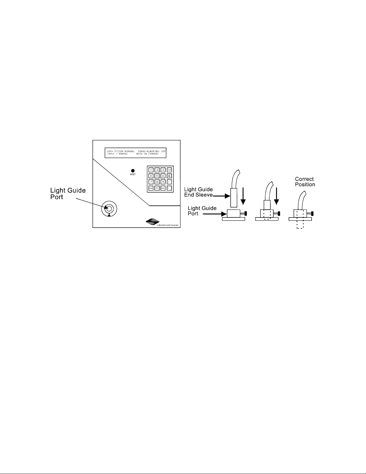
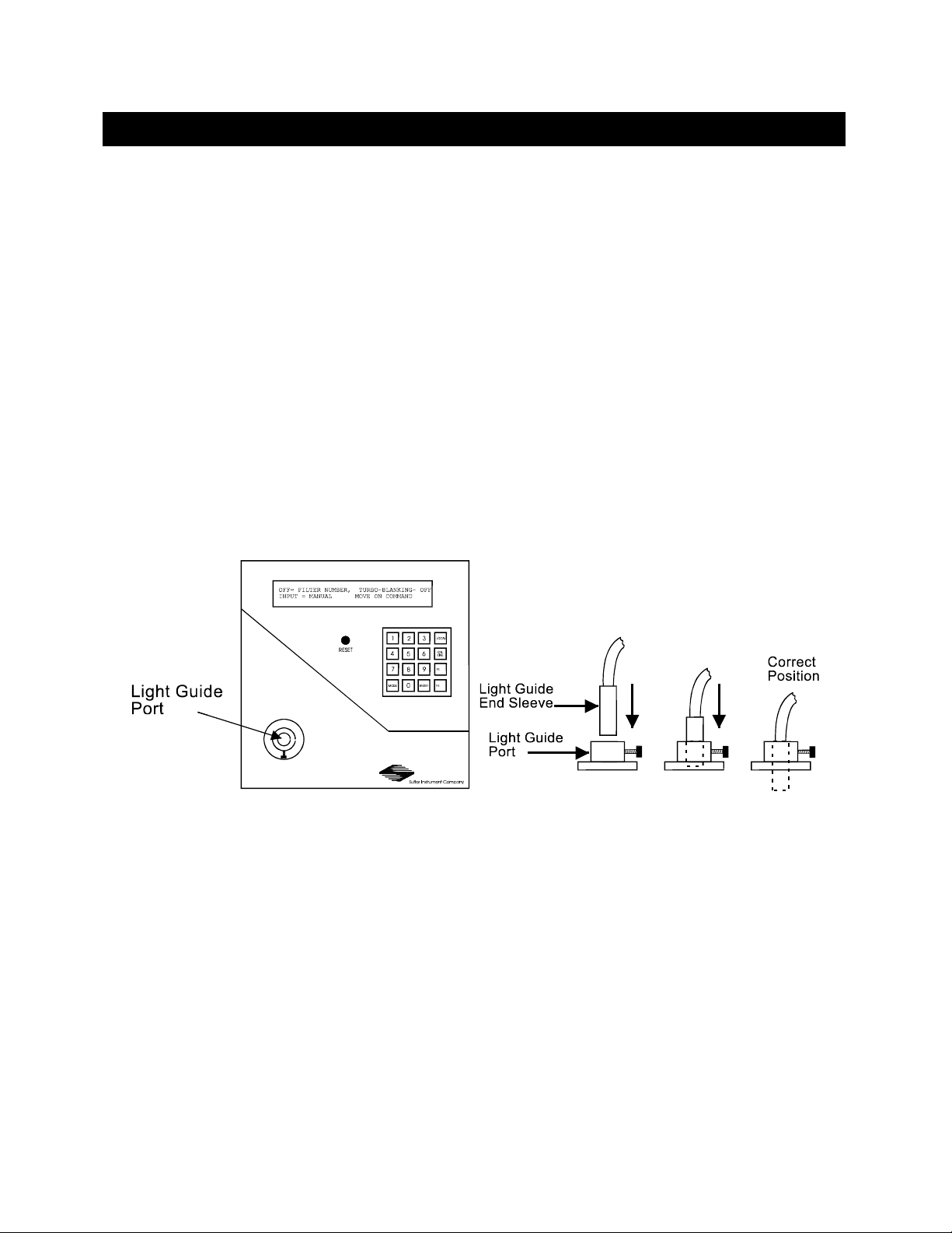
2. Insert either end of the light guide into the port on the top panel of the Lambda DG-4
cabinet (see below) and tighten the thumbscrew to hold it in place. The top of the light
guide end sleeve should be flush with the top surface of the port fitting (see below). This
should result in maximal or near-maximal light output from the light guide. Minor
adjustments up from this position may improve output, and can be easily made once the
system is fully installed.
Figure 3-2. Light guide installation.
3. The other end of the light guide should be installed in the microscope using the
appropriate adapters (see the installation sheet provided with the specific adapter that
has been ordered) or directed away from anyone’s eyes and toward a non-reflective
surface. DO NOT LOOK DIRECTLY INTO THE LIGHT GUIDE!
4. A hose should be connected to the 4” fitting on the back of the Lambda DG-4 cabinet to
ventilate the ozone from the xenon lamp to the environment or to an ozone removal
device.
5. Identify the small access door used to install the neutral density FILTER HOLDER.
This access door is located near the top edge of the left side panel on the Lambda DG-4
cabinet (see below). Loosen the black knob on the access door and slide it up to install
the empty Neutral Density FILTER HOLDER (the neutral density FILTER HOLDER
is the one whose bottom surface is flat rather than grooved). Make certain that the end
nearest the filter cup goes in first. If you would like to install a neutral density filter at
this time please refer to the “Loading Filters” section of this manual.
LAMBDA DG-4 & DG-5 OPERATION MANUAL – REV. 2.14 (20081107)
Page 15

7
Figure 3-3. Lambda DG-4 left side.
6. Identify the large access door used to install the interference FILTER HOLDERS. This
access door is located in the middle of the left side panel on the Lambda DG-4 cabinet
(see above). Loosen the black knob on the access door and slide it up to install the
remaining four FILTER HOLDERS (the ones that have a groove on their bottom
surface). Install the two FILTER HOLDERS that contain blanking disks in FILTER
POSITIONS 3 and 4. If you would like to install interference filters at this time, please
refer to the “Loading Filters” section of this manual.
7. Make certain that the free end of the light guide is installed into the microscope or is
directed toward a non-reflective surface and away from anyone’s eyes. DO NOT LOOK
DIRECTLY INTO THE LIGHT GUIDE.
8. Turn on the power to the lamp subsystem using the switch labeled LAMP on the back
panel of the Lambda DG-4 cabinet. Due to the current draw during lamp ignition, it is
important to power up the LAMP first (before the MAIN switch is turned on) to avoid
damage to the circuitry of the other Lambda DG-4 subsystems. This same precaution
applies to the order in which you power up other electronic and computer equipment that
might be powered from or grounded to the same circuit as the one used for the Lambda
DG-4. GO DIRECTLY TO THE NEXT STEP! DO NOT OPERATE THE LAMP FOR
MORE THAN A FEW SECONDS WITHOUT TURNING ON THE MAIN POWER
SWITCH!
9. Within a few seconds of turning on the LAMP switch turn on the power to the optical
path and controller subsystems using the switch labeled MAIN on the back panel of the
LAMBDA DG-4 & DG-5 OPERATION MANUAL – REV. 2.14 (20081107)
Page 16

8
Lambda DG-4 cabinet. The Lambda DG-4 will boot up and briefly display the
initialization screen followed by the MAIN MENU (shown on top of next page).
OFF= FILTER NUMBER, TURBO-BLANKING- OFF
OFF= FILTER NUMBER, TURBO-BLANKING- OFF
OFF= FILTER NUMBER, TURBO-BLANKING- OFFOFF= FILTER NUMBER, TURBO-BLANKING- OFF
INPUT = MANUAL MOVE ON COMMAND
INPUT = MANUAL MOVE ON COMMAND
INPUT = MANUAL MOVE ON COMMAND INPUT = MANUAL MOVE ON COMMAND
10. The Lambda DG-4 is under LOCAL (keypad) control upon start-up, as indicated by the
words “INPUT - MANUAL” on the MAIN MENU (see above). MOVE ON COMMAND is
the active operational mode at start-up, which means that filters are selected by pressing
the numeric keys corresponding to the desired FILTER NUMBER (see EDIT A FILTER
NUMBER definition of this value). The default FILTER NUMBER upon start-up is “0”.
This setting will disrupt the optical pathway within the Lambda DG-4 and prevent any
light output at the light guide port. The “0” FILTER NUMBER serves, then, as a
“shutter” whenever it is selected.
11. Press the “1” key followed by ENTER. This FILTER NUMBER is pre-programmed at
the factory to cause the light to be directed through the FILTER HOLDER that is loaded
into position 1 and then onto the light guide with maximal light output (i.e., minimal
attenuation).
12. Now experiment by selecting FILTER NUMBERS 0 through 4. Anytime you select a
single digit FILTER NUMBER you must complete the entry by pressing the ENTER key
or you must precede the single digit with a “0”. FILTER NUMBERS 0,1,2,3 and 4 are
pre-programmed to correspond with the closed “shutter” and the four FILTER
POSITIONS (with minimal attenuation), respectively.
Now that you have completed the “Make it Glow” section of the manual, you should be
familiar with the basic components and operation of the Lambda DG-4. To get set up for an
experimental application you will need to:
Install the LIGHT GUIDE into the OPTICAL HOLDER (if not already in place).
Install the OPTICAL HOLDER into the microscope using the appropriate adapter (if not
already in place).
Install the desired filters into the FILTER HOLDERS (if not already in place).
Program the desired FILTER NUMBERS.
Establish the desired interface between the Lambda DG-4 and your computer.
Each of these steps is discussed in the following sections of the manual.
LAMBDA DG-4 & DG-5 OPERATION MANUAL – REV. 2.14 (20081107)
Page 17
9
4.
4. O PTIC AL P ATH W AY
OPT ICAL PA T HWA Y
4.4.
OPT ICAL PA T HWA YOPT ICAL PA THWA Y
4.1
4.1 Light Guide & Optical Holder Installation
Light Guide & Optical Holder Installation
4.14.1
Light Guide & Optical Holder InstallationLight Guide & Optical Holder Installation
4.1.1
4.1.1 Liquid Light Guide
Liquid Light Guide
4.1.14.1.1
Liquid Light GuideLiquid Light Guide
The light output of the Lambda 10 DG4 is focused onto one end of a liquid light guide. The
output of the liquid light guide can then easily be coupled to your microscope or optical
system using correct mechanical adapter for your microscope. Please note that the light
guide has a minimum-bending radius of 40 mm (about 1.6 inches).
4.1.2
4.1.2 Liquid Light Guide Installation
Liquid Light Guide Installation
4.1.24.1.2
Liquid Light Guide InstallationLiquid Light Guide Installation
The liquid light guide should have black sleeves over the ferrules on both ends. These
ferrules, or “end sleeves”, are designed to slide into the mounting flange on the lambda DG-4
cabinet and the output adapter. Insert the end of the light guide into the light guide port
until the top of the black end sleeve is even with the top of the light guide port. Tighten the
locking screw on light guide port to secure the end of the light guide in position. This should
result in maximal or near-maximal light output from the light guide. Minor adjustments up
from this position may improve output; the adjustments can be easily made once the system
is fully installed.
Figure 4-1. Liquid light guide installation.
LAMBDA DG-4 & DG-5 OPERATION MANUAL – REV. 2.14 (20081107)
Page 18
10
4.1.3
4.1.3 Optical Holder
Optical Holder
4.1.34.1.3
Optical Holder Optical Holder
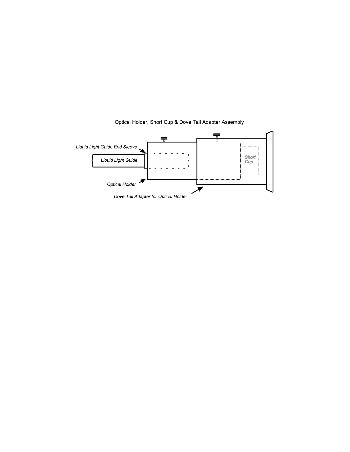
The free end of the light guide slides into one end of the optical holder tube (shown below).
The other end of the optical holder tube has a UV grade fused silica lens system (in the
“short cup”). By sliding the light guide toward or away from these lenses, the light guide
output can be collimated or brought to a focus. The optical holder, in turn, slides into the
dovetail adapter, which has a “dovetail” collar on one end. This collar is used to fasten the
entire assembly to the microscope system using an adapter (not shown) that is specific to the
microscope make and model. Refer to the documentation included with each microscope
adapter for further installation instructions.
Figure 4-2. Light guide optical holder.
4.2
4.2 Loading Filters
Loading Filters
4.24.2
Loading FiltersLoading Filters
4.2.1
4.2.1 Filter Orientation
Filter Orientation
4.2.14.2.1
Filter OrientationFilter Orientation
The two sides of a filter are usually not identical due to differences in their surface coatings.
Some form of labeling will be present to differentiate the two sides. It is important to refer
to the filter manufacturer’s documentation to interpret the labeling and determine the
proper orientation relative to the light source. Remember, the light path inside the Lambda
DG-4 travels from BOTTOM TO TOP. Therefore, the filters should be oriented with their
“Lamp Side” down.
LAMBDA DG-4 & DG-5 OPERATION MANUAL – REV. 2.14 (20081107)
Page 19
4.2.2
4.2.2 Loading Filters
Loading Filters
4.2.24.2.2
Loading FiltersLoading Filters
11
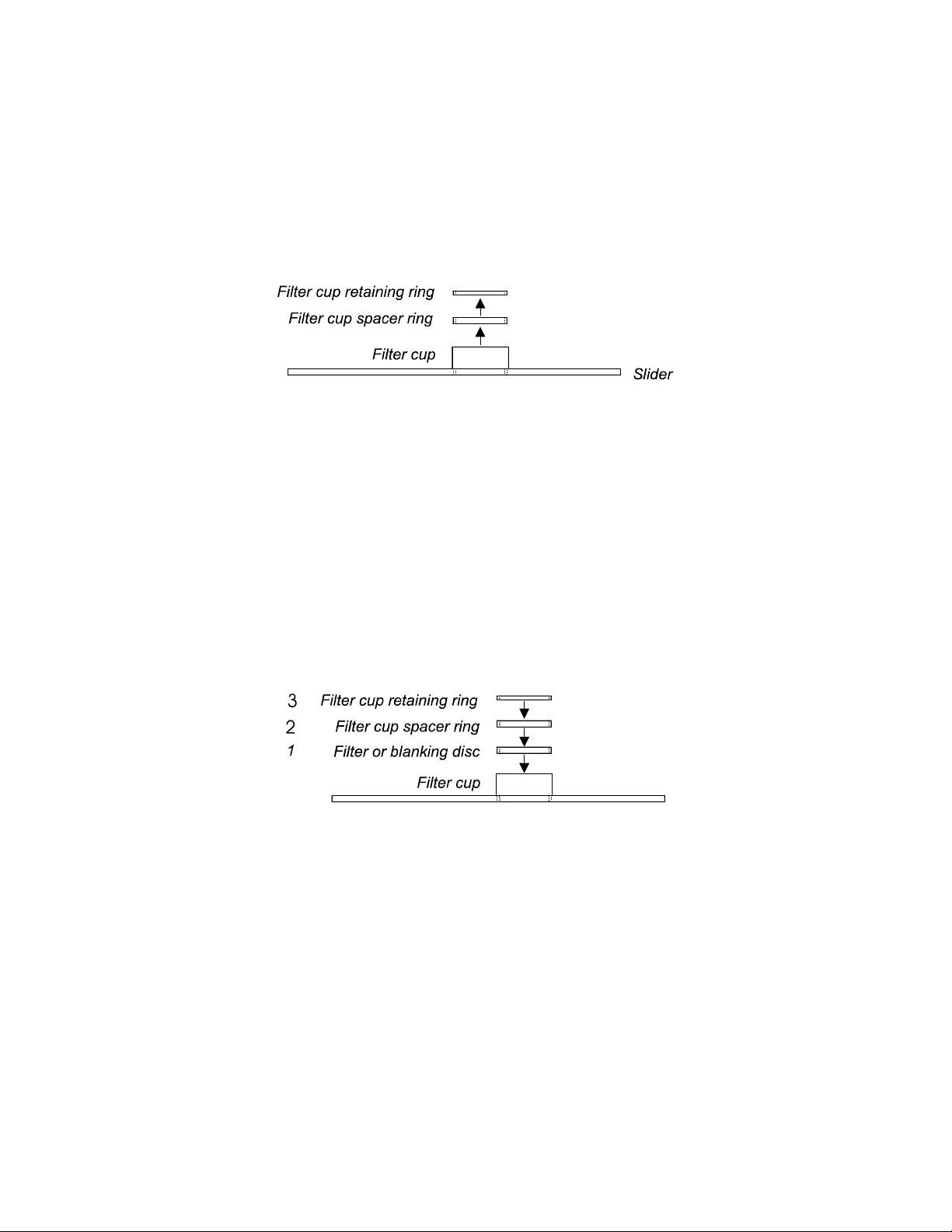
At the end of each filter holder is a filter cup assembly (shown below). There are at least two
items installed into the filter cup at the factory: a threaded retaining ring and a spacer ring
(to carry the force of the retaining ring to the unthreaded portion at the bottom of the cup).
In two of the filter cups, there will also be a blanking disc. Installation of filters into the
filter holders requires care and patience to avoid damaging the threads of the filter cups and
retaining rings as well as the filters.
Figure 4-3. Filter holder assembly.
The threaded retaining ring has two notches cut into it, 180 degrees apart. Place the
notched end of the brass spanner wrench into the notches on the retaining ring and carefully
unscrew it. If a retaining ring has been previously over-tightened, it is possible that the filter
cup will begin to unscrew from the slider. If this occurs, STOP. Turn the spanner wrench
around and, using the other end, insert it into the slots at the top of the cup. Then screw the
cup back into the slider. DO NOT push on the cup. Just screw it in until it seats firmly. It
should then be possible to remove the retaining ring.
Once the retaining ring is removed, the spacer (and blank, if present) should fall out. You
should become familiar with the assembly of this retaining system. In particular, you should
develop a feel for tightening the retaining ring without pushing on the wrench. This is
important because if you forcefully push on the filter holder while you are trying to load a
filter, you run the risk of scratching the filter.
Figure 4-4. Filter holder assembly with blanking disc.
Place the desired filter into the filter cup, first. With some 1” filters extra care must be
taken to avoid getting the filters jammed at an angle inside the filter cup.
Next, install the spacer ring into the filter cup. Unless the filter thickness precludes the use
of the spacer ring, always install the spacer to provide maximum separation between the
filter surface and end of the brass spanner wrench that is used to turn the retaining ring.
Finally, install the threaded retaining ring.
CAUTION: DO NOT OVER TIGHTEN THE RETAINING RING!
CAUTION: DO NOT OVER TIGHTEN THE RETAINING RING!
CAUTION: DO NOT OVER TIGHTEN THE RETAINING RING!CAUTION: DO NOT OVER TIGHTEN THE RETAINING RING!
LAMBDA DG-4 & DG-5 OPERATION MANUAL – REV. 2.14 (20081107)
Page 20

12
4.2.3
4.2.3 Selection of a Filter Position
Selection of a Filter Position
4.2.34.2.3
Selection of a Filter PositionSelection of a Filter Position
In most cases, any given filter could be installed at any of the four FILTER POSITIONS.
However, some minor considerations may improve performance of the system. Adjacent
FILTER POSITIONS will require slightly less switching time. Therefore, if an experiment
will require rapid switching between two filters they should be located next to one another.
If separated by one or more filters, there will be brief transitions through the intervening
filter(s) unless the TURBO-BLANKING feature is enabled (see “Modes of Operation”).
While this feature eliminates the transmission of light at unwanted wavelengths, it does
further increase the time required for switching.
4.2.4
4.2.4 Blanking Discs
Blanking Discs
4.2.44.2.4
Blanking DiscsBlanking Discs
The blanking discs should only be removed from those positions that will contain a filter.
The discs are intended as a safety device for the occasion where you may be looking into the
microscope. We strongly urge that the discs be used. Please be careful and avoid the
possibility of direct visualization of high intensity light.
4.2.5
4.2.5 Neutral Density Filters
Neutral Density Filters
4.2.54.2.5
Neutral Density FiltersNeutral Density Filters
. Filter installation is the same for this filter holder as described above. The slide portion of
the neutral density filter holder, however, is mechanically different from those used for the
interference filters. As a result, the two types of holders may not be interchanged.
LAMBDA DG-4 & DG-5 OPERATION MANUAL – REV. 2.14 (20081107)
Page 21
13
4.2.6
4.2.6 Filter Holder Installation
Filter Holder Installation
4.2.64.2.6
Filter Holder InstallationFilter Holder Installation
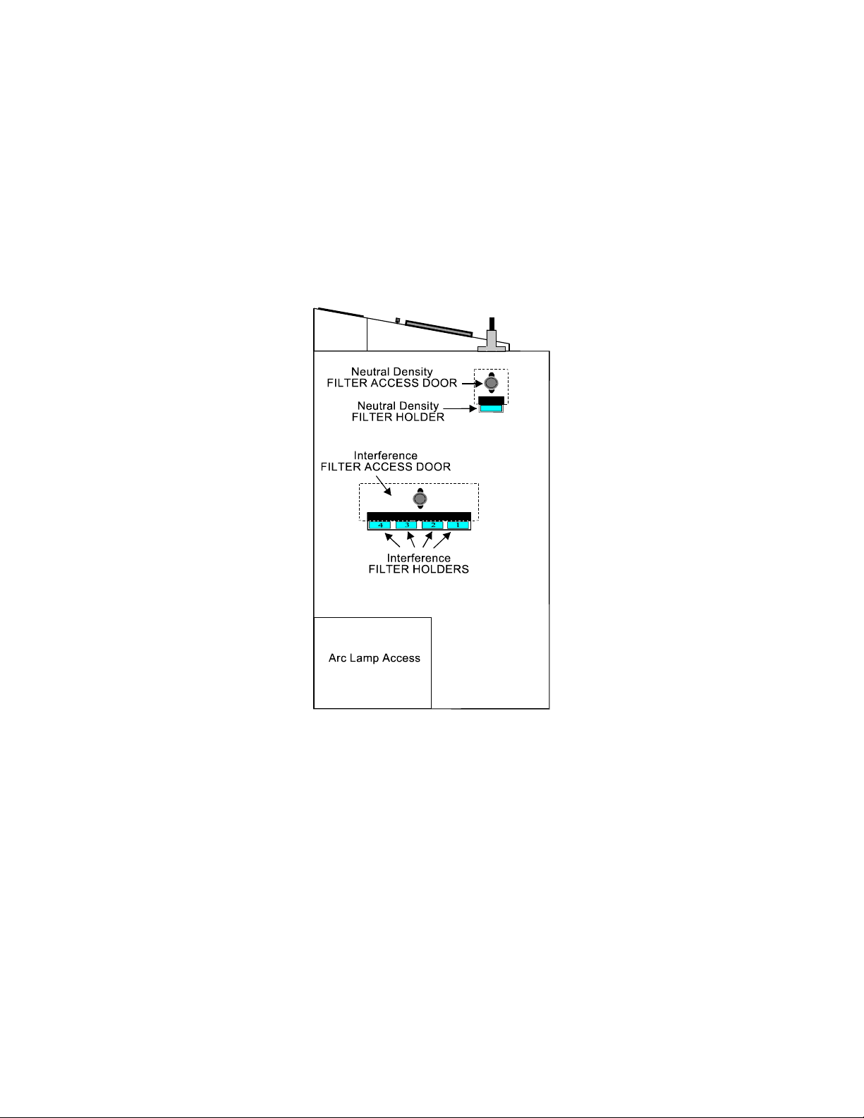
Identify the access doors used to install the neutral density FILTER HOLDER and the four
interference FILTER HOLDERS. The small access door located near the top edge of the left
side panel on the Lambda DG-4 cabinet (see below) is for the neutral-density FILTER
HOLDER. The larger door in the middle of the left side panel is fro the interference
FILTER HOLDER. Loosen the black knob on these access doors to slide them up and install
the appropriate FILTER HOLDER into the slot. The bottom of the neutral density FILTER
HOLDER is flat while the bottoms of the interference FILTER HOLDERS are grooved. For
this reason, these two types of FILTER HOLDERS are not interchangeable. Make certain
that the end nearest the filter cup goes in first.
Figure 4-5. Lambda DG-4 left side.
LAMBDA DG-4 & DG-5 OPERATION MANUAL – REV. 2.14 (20081107)
Page 22

Page 23

15
5.
5. C O NTR OLL E R
CON TROL LER
5.5.
CON TROL LERCON TROL LER
Although the Lambda DG-4 is simple to use, proper operation depends on the user
understanding the design and characteristics of this instrument. This section provides the
detailed information needed to begin operation and to control the unit from its keypad.
5.1
5.1 Control Electronics
Control Electronics
5.15.1
Control ElectronicsControl Electronics
The control electronics for the filter changer are activated by the “MAIN” power switch on
the rear of the unit. You may operate the control electronics without the lamp on, but it is
best to turn the control electronics off before the lamp is started. Once the lamp has been
started, the control electronics may be turned on again.
5.2
5.2 Power
Power----up Sequence
5.25.2
PowerPower
There are two switches on the back of the Lambda DG-4 labeled LAMP and MAIN. The
LAMP switch will ignite and power the xenon lamp. The MAIN switch applies power to the
controller and the fan that cools all of the electronics (including the xenon lamp power
supply). The MAIN switch should be turned on immediately after the LAMP switch is
turned on. If you are only configuring the Lambda DG-4 controller or a computer interface,
you do not need to switch on the LAMP before turning on the MAIN switch. The following
message will be briefly displayed on the front panel when the MAIN switch is turned on:
After a few seconds the MAIN MENU will be displayed:
At this point, the Controller subsystem is ready for operation.
up Sequence
up Sequenceup Sequence
SUTTER FAST FILTER CONTROLLER PROGRAM
SUTTER FAST FILTER CONTROLLER PROGRAM
SUTTER FAST FILTER CONTROLLER PROGRAM SUTTER FAST FILTER CONTROLLER PROGRAM
COPYRIGHT SUTTER INSTRUMENT CORP. 2006
COPYRIGHT SUTTER INSTRUMENT CORP. 2006
COPYRIGHT SUTTER INSTRUMENT CORP. 2006 COPYRIGHT SUTTER INSTRUMENT CORP. 2006
OFF= FILTER NUMBER, TURBO-BLANKING- OFF
OFF= FILTER NUMBER, TURBO-BLANKING- OFF
OFF= FILTER NUMBER, TURBO-BLANKING- OFFOFF= FILTER NUMBER, TURBO-BLANKING- OFF
INPUT = MANUAL MOVE ON COMMAND
INPUT = MANUAL MOVE ON COMMAND
INPUT = MANUAL MOVE ON COMMAND INPUT = MANUAL MOVE ON COMMAND
When the unit is first turned on, the FILTER NUMBER
indicates that the filter selecting mirrors have been positioned to prevent lamp output from
the device. The status of the TURBO
OFF is the default setting for that feature when the controller is first powered up.
The second line of the display indicates if the unit is under local control and that the unit
will execute all commands as they are received.
The unit selects the PARALLEL MODE as the default remote interface at power on. If the
unit is under remote control at power on, the appropriate remote interface mode will be
automatically set and the display may change immediately to reflect any waiting computer
commands.
LAMBDA DG-4 & DG-5 OPERATION MANUAL – REV. 2.14 (20081107)
TURBO----BLANKING
TURBOTURBO
FILTER NUMBER display will read “OFF”. This
FILTER NUMBERFILTER NUMBER
BLANKING feature (discussed below) is also shown;
BLANKINGBLANKING
Page 24

16
5.3
5.3 Top Panel Controls
Top Panel Controls
5.35.3
Top Panel ControlsTop Panel Controls
5.3.1
5.3.1 Keypad
Keypad
5.3.15.3.1
KeypadKeypad
Figure 5-1. Keypad (top panel).
There are 16 keys on the Lambda DG-4 keypad. The numerical keys 0 to 9 and six function
keys. Keys are read while depressed but the appropriate action will occur only when the key
is released. If a key is pressed while a move is in progress but released after the move is
over, the key will read normally. Keys pressed and released while a move is in progress are
ignored. In the REMOTE MODE only the LOCAL key is active. Holding any other key
down while in the REMOTE MODE may cause an interruption in the reading of new
commands from the remote computer. The functions of the keys are as follows:
0000----9999 These keys are used to select modes and make numerical entries while in the various
modes of operation. In the MOVE ON COMMAND mode, for example, a FILTER NUMBER
may be selected with these keys.
F1, F2
F1, F2 These key are presently used to manually increase or decrease the Output
F1, F2 F1, F2
Galvanometer Value (see EDIT A FILTER VALUE DEFINITION).
LOCAL
LOCAL Pressing this key puts the unit under LOCAL control. This is the only key that has
LOCALLOCAL
an effect when the Lambda DG-4 is ON LINE (i.e., under the remote control of an interfaced
external source, such as a computer.
ON LINE
ON LINE This key transfers control of the Lambda DG-4 to an interfaced external source,
ON LINE ON LINE
such as a computer. This transfer can also be done by sending the correct signal from the
external source as outlined under the interfacing section. The default input port is the
PARALLEL PORT, so the display will indicate PARALLEL MODE after the ON LINE key
has been pressed (unless the SERIAL PORT is active).
ENTER
ENTER This key is used in conjunction with the numeric keys for selecting FILTER
ENTERENTER
NUMBERS and entering other numeric data. It is also used to exit certain set-up modes
when data entry has been completed.
MODE
MODE This key is used to locally to set the mode of operation and to access setup modes.
MODEMODE
This key does not directly relate to the mode of input. Pressing the MODE key will initiate a
mode selection routine, which will present a series of linked menus (see the section on
“Selecting an Operational Mode”).
RESET
RESET Pressing the RESET button at any time causes the control unit to start the power-
RESETRESET
up sequence outlined above. The sequence starts with a delay after the end of the buttonpress. The display will be cleared until the initialization screen is written.
5.4
5.4 Electrical Connections
Electrical Connections
5.45.4
Electrical ConnectionsElectrical Connections
All Electrical connections are made on the rear panel of the Lambda DG-4.
LAMBDA DG-4 & DG-5 OPERATION MANUAL – REV. 2.14 (20081107)
Page 25

17
Figure 5-2. Electrical connections (rear panel).
5.4.1
5.4.1 Parallel Port
Parallel Port
5.4.15.4.1
Parallel PortParallel Port
This 25-pin DSUB connector is used for establishing a parallel interface between the
Lambda DG-4 and a remote device (computer) using the cable provided. This cable should
not be used simultaneously with the serial port cable.
5.4.2
5.4.2 Serial Port
Serial Port
5.4.25.4.2
Serial PortSerial Port
This 9-pin DSUB connector is used for establishing a serial interface between the Lambda
DG-4 and a remote device (computer) using the cable provided. This cable should not be
used simultaneously with the parallel port cable.
5.4.3
5.4.3 Filter Value Out
Filter Value Out
5.4.35.4.3
Filter Value OutFilter Value Out
This 8-pin, Modular connector provides a digital indicator of the value of the FILTER
NUMBER in use. Pin numbers 1 through 4 correspond to the bit number of the 4-bit binary
equivalent of the decimal FILTER NUMBER value. Pin 5 carries the BUSY line signal and
pins 6 through 8 are tied to ground.
LAMBDA DG-4 & DG-5 OPERATION MANUAL – REV. 2.14 (20081107)
Page 26

18
Figure 5-3. Filter value out connector.
5.4.4
5.4.4 Sync
Sync
5.4.45.4.4
SyncSync
This BNC connector is the video synchronization input. NOTE: THIS INPUT IS NOT
INTERNALLY GROUNDED. If the ground in the camera being used is floating, the
camera’s synchronization signal to the Lambda DG-4 SYNC input will cause the
galvanometers to oscillate at a high, irregular rate.
5.4.5
5.4.5 DAC
DAC
5.4.55.4.5
DACDAC
This BNC connector provides an analog indicator of the current FILTER NUMBER:
DAC Output = FILTER NUMBER x 400 mV
DAC Output = FILTER NUMBER x 400 mV
DAC Output = FILTER NUMBER x 400 mVDAC Output = FILTER NUMBER x 400 mV
5.4.6
5.4.6 Strobe
Strobe
5.4.65.4.6
StrobeStrobe
This BNC connector is the “trigger” input for the MOVE ON TRIGGER mode of operation.
5.4.7
5.4.7 Line Power
Line Power
5.4.75.4.7
Line PowerLine Power
This socket is used to connect the power cord provided with the Lambda DG-4.
5.5
5.5 Fuse
Fuse
5.55.5
FuseFuse
The fuse used in this instrument depends on the power rating of the installed lamp and
mains voltage. See Appendix A: FUSE REPLACEMENT for fuse-type details and fuse
installation.
LAMBDA DG-4 & DG-5 OPERATION MANUAL – REV. 2.14 (20081107)
Page 27

19
5.6
5.6 Modes of Operation (LOCAL)
Modes of Operation (LOCAL)
5.65.6
Modes of Operation (LOCAL)Modes of Operation (LOCAL)
5.6.1
5.6.1 General Information
General Information
5.6.15.6.1
General InformationGeneral Information
Filter switch timing can be controlled using one of four different operational modes.
• MOVE ON COMMAND (default mode)
• MOVE ON STROBE PULSE
• MOVE ON SYNC PULSE
• MOVE ON SYNC PULSE, INHIBITED BY THE STROBE LINE
The default mode (“MOVE ON COMMAND”) allows you to directly command filter changes
(e.g., using the numeric keys on the keypad when the Lambda DG-4 is under LOCAL
(“Manual”) control). Filter changes can also be controlled using an external trigger (“MOVE
ON STROBE PULSE”), video synchronization pulse (“MOVE ON SYNC PULSE”) or a
combination of these two external sources (“MOVE ON SYNC PULSE, INHIBITED BY
THE STROBE LINE”). By default, the Lambda DG-4 will be in the MOVE ON COMMAND
mode when it starts up, and at any time after a “triggered” mode has been inactivated. The
active operational mode (of these four) will be indicated on the right side of the bottom line
in the MAIN MENU.
In addition to the above operational modes that control the timing of the filter changes,
there are four others available which alter the Lambda DG-4’s function:
• EDIT A FILTER DEFINITION
• SETUP THE RING BUFFER
• TURBO-BLANKING
• DISPLAY THE FIRST 4 FILTER VALUES
All of the eight operational modes listed above may be accessed from any one of the three
sources of control input, LOCAL (keypad), SERIAL PORT or PARALLEL PORT. Although
the details of how an operational mode is selected may vary somewhat from one source of
input to another, its function remains the same. In this section, the operational modes will
be described in terms of LOCAL control. Separate sections discussing interfacing the
Lambda DG-4 with remote devices (computers) will cover access to these same modes of
operation using SERIAL and. PARALLEL inputs.
LAMBDA DG-4 & DG-5 OPERATION MANUAL – REV. 2.14 (20081107)
Page 28

20
5.6.2
5.6.2 Selecting an Operational
Selecting an Operational Mode: The MODE Key
5.6.25.6.2
Selecting an OperationalSelecting an Operational
[MODE/1]
[MODE/1]
[MODE/1][MODE/1]
When the MAIN MENU is displayed, the MODE
Mode: The MODE Key
Mode: The MODE Key Mode: The MODE Key
MODE button on the keypad is used to start a
MODEMODE
mode selection routine. This routine will present options using a series of linked menus
(shown below). Each of the menus will give you the following choices:
• EXIT the mode selection routine and return to the MAIN MENU (press 0000)
• Go to the NEXT PAGE (press 1111)
• Select an OPERATIONAL MODE from the one or more options presented on the menu
(press the numeric key corresponding to the desired mode)
The series of menus in this routine and their options are as follows:
0=EXIT, 1=NEXT PAGE, 2 = TURBO BLANKING
0=EXIT, 1=NEXT PAGE, 2 = TURBO BLANKING
0=EXIT, 1=NEXT PAGE, 2 = TURBO BLANKING 0=EXIT, 1=NEXT PAGE, 2 = TURBO BLANKING
3 = DISPLAY THE FIRST 4 FILTER VALU
3 = DISPLAY THE FIRST 4 FILTER VALUES
3 = DISPLAY THE FIRST 4 FILTER VALU3 = DISPLAY THE FIRST 4 FILTER VALU
ES
ES ES
Pressing the 0000 key will return to the MAIN MENU. Repeatedly pressing 1111 for the NEXT
PAGE produces the following succession of menus:
0=EXIT, 1=NEXT PAGE. 4= MOVE ON SYNC.
0=EXIT, 1=NEXT PAGE. 4= MOVE ON SYNC.
0=EXIT, 1=NEXT PAGE. 4= MOVE ON SYNC. 0=EXIT, 1=NEXT PAGE. 4= MOVE ON SYNC.
PULSE, 5 FOR MOVE ON STROBE PULSE
PULSE, 5 FOR MOVE ON STROBE PULSE
PULSE, 5 FOR MOVE ON STROBE PULSE PULSE, 5 FOR MOVE ON STROBE PULSE
0=EXIT, 1=NEXT PAGE. PRESS 6 FOR MOVE ON
0=EXIT, 1=NEXT PAGE. PRESS 6 FOR MOVE ON
0=EXIT, 1=NEXT PAGE. PRESS 6 FOR MOVE ON0=EXIT, 1=NEXT PAGE. PRESS 6 FOR MOVE ON
SYNC, INHIBITED BY THE STROBE LINE
SYNC, INHIBITED BY THE STROBE LINE
SYNC, INHIBITED BY THE STROBE LINE SYNC, INHIBITED BY THE STROBE LINE
0=EXIT, 1=NEXT PAGE. 7 = EDIT A FILTER
0=EXIT, 1=NEXT PAGE. 7 = EDIT A FILTER
0=EXIT, 1=NEXT PAGE. 7 = EDIT A FILTER 0=EXIT, 1=NEXT PAGE. 7 = EDIT A FILTER
DEFINITION, 8 = SETUP THE RING BUFFER
DEFINITION, 8 = SETUP THE RING BUFFER
DEFINITION, 8 = SETUP THE RING BUFFER DEFINITION, 8 = SETUP THE RING BUFFER
Pressing 1111 again at this point will not produce further screens.
The above menus are of informational value, only. Once the MODE button has been pressed
any one of the seven operational modes presented (# 2 through 8) can be selected by pressing
the corresponding numeric key. For example, to set the MOVE ON SYNC PULSE mode,
simply press the MODE
MODE key, followed by the 4444 key to directly access that mode’s menu.
MODEMODE
LAMBDA DG-4 & DG-5 OPERATION MANUAL – REV. 2.14 (20081107)
Page 29

5.6.3
5.6.3 Move on Command Mode
Move on Command Mode
5.6.35.6.3
Move on Command ModeMove on Command Mode
[1 through 15]
[1 through 15]
[1 through 15] [1 through 15]
Selecting a new filter: The numeric keys.
Selecting a new filter: The numeric keys.
Selecting a new filter: The numeric keys.Selecting a new filter: The numeric keys.
MOVE ON COMMAND mode, and under LOCAL control (“manual mode”) when it starts
up, unless remote commands are waiting on an interfaced device connected to an input port.
The default FILTER NUMBER will be 0, yielding no light output. Selection of a new
FILTER NUMBER is made using the keypad, and will immediately yield light through the
FILTER POSITION and at the ATTENUATION level previously programmed for that
FILTER NUMBER value (see the section on SETUP modes). Under LOCAL control, the
filter is selected by entering a value in the range of 0 to 15. If a single digit value is desired,
the user may either press 0000 and then the correct numeric key or just the single correct
numeric key followed by ENTER. If the value is a 2-digit number, press the correct 2 keys (1111
and then the second key) but do not press ENTER
a numeric key will select 0
a numeric key will select 0. Consequently, if you press a 2-digit number correctly and then
a numeric key will select 0a numeric key will select 0
press ENTER
ENTER you will briefly select the filter you desired and then filter 0 (closing the
ENTERENTER
“shutter”). The following examples demonstrate the two methods of entering a single digit
FILTER NUMBER (8 in this case).
By default, the Lambda DG-4 will be in the
ENTER. Pressing ENTER without first pressing
ENTERENTER
Pressing ENTER without first pressing
Pressing ENTER without first pressing Pressing ENTER without first pressing
21
Method 1: The main menu would look like this if the initial FILTER NUMBER = 10
10 = FILTER NUMBER, TURBO-BLANKING- OFF
10 = FILTER NUMBER, TURBO-BLANKING- OFF
The numeric key 8888 is then pressed to call for FILTER NUMBER = 8.
When the ENTER
Method 2: The main menu will look like this if the initial FILTER NUMBER = 10
The numeric key 0000 is pressed first.
ENTER key is then pressed, FILTER NUMBER 8 is then displayed correctly.
ENTERENTER
10 = FILTER NUMBER, TURBO-BLANKING- OFF10 = FILTER NUMBER, TURBO-BLANKING- OFF
INPUT = MANUAL MOVE ON
INPUT = MANUAL MOVE ON COMMAND
INPUT = MANUAL MOVE ON INPUT = MANUAL MOVE ON
80 = FILTER NUMBER, TURBO-BLANKING- OFF
80 = FILTER NUMBER, TURBO-BLANKING- OFF
80 = FILTER NUMBER, TURBO-BLANKING- OFF80 = FILTER NUMBER, TURBO-BLANKING- OFF
INPUT = MANUAL MOVE ON COMMAND
INPUT = MANUAL MOVE ON COMMAND
INPUT = MANUAL MOVE ON COMMAND INPUT = MANUAL MOVE ON COMMAND
8 = FILTER NUMBER, TURBO-BLANKING- OFF
8 = FILTER NUMBER, TURBO-BLANKING- OFF
8 = FILTER NUMBER, TURBO-BLANKING- OFF 8 = FILTER NUMBER, TURBO-BLANKING- OFF
INPUT = MANUAL MOVE ON COMMAND
INPUT = MANUAL MOVE ON COMMAND
INPUT = MANUAL MOVE ON COMMAND INPUT = MANUAL MOVE ON COMMAND
10 = FILTER NUMBER, TURBO-BLANKING- OFF
10 = FILTER NUMBER, TURBO-BLANKING- OFF
10 = FILTER NUMBER, TURBO-BLANKING- OFF10 = FILTER NUMBER, TURBO-BLANKING- OFF
INPUT = MANUAL M
INPUT = MANUAL MOVE ON COMMAND
INPUT = MANUAL MINPUT = MANUAL M
OVE ON COMMAND
OVE ON COMMAND OVE ON COMMAND
COMMAND
COMMAND COMMAND
LAMBDA DG-4 & DG-5 OPERATION MANUAL – REV. 2.14 (20081107)
Page 30

22
00 = FILTER NUMBER, TURBO-BLANKING- OFF
00 = FILTER NUMBER, TURBO-BLANKING- OFF
00 = FILTER NUMBER, TURBO-BLANKING- OFF00 = FILTER NUMBER, TURBO-BLANKING- OFF
INPUT = MANUAL MOVE ON COMMAND
INPUT = MANUAL MOVE ON COMMAND
INPUT = MANUAL MOVE ON COMMAND INPUT = MANUAL MOVE ON COMMAND
The numeric key 8888 is pressed next with no further action required. FILTER NUMBER 8 is
then displayed correctly.
8 = FILTER NUMBER, TURBO-BLANKING- OFF
8 = FILTER NUMBER, TURBO-BLANKING- OFF
8 = FILTER NUMBER, TURBO-BLANKING- OFF 8 = FILTER NUMBER, TURBO-BLANKING- OFF
INPUT = MANUAL MOVE ON COMMAND
INPUT = MANUAL MOVE ON COMMAND
INPUT = MANUAL MOVE ON COMMAND INPUT = MANUAL MOVE ON COMMAND
LAMBDA DG-4 & DG-5 OPERATION MANUAL – REV. 2.14 (20081107)
Page 31

23
5.6.4
5.6.4 Move on Sync Pulse Mode
Move on Sync Pulse Mode
5.6.45.6.4
Move on Sync Pulse Mode Move on Sync Pulse Mode
[MODE/4]
[MODE/4]
[MODE/4] [MODE/4]
If the Move on Sync Pulse Mode is active, the controller will advance to the next filter in a
previously programmed FILTER NUMBER sequence (Ring Buffer) when an internal video
synchronization (sync) circuit detects the vertical sync pulse of a composite video signal
applied to the SYNC input on the rear of the Lambda DG-4. In this way, filter changes can
be coordinated to occur with the capture of video “frames”. The FILTER NUMBER
sequence can be programmed at your convenience and then executed later with precise
timing (see SET UP THE RING BUFFER). The FILTER NUMBERS can also be sent
individually via the serial or parallel port before the trigger event. This operational mode is
selected by pressing the MODE key followed by the 4444 key to get to the MOVE ON SYNC
PULSE menu. Alternatively, you can “page” through the mode selection menus by pressing
MODE followed by the 1 key. The following menu will be displayed:
0=EXIT, 1=NEXT PAGE, 2 = TURBO BLANKING
0=EXIT, 1=NEXT PAGE, 2 = TURBO BLANKING
Press 1111 for the NEXT PAGE to see the desired option or press the 0000 key to abort the routine
and return to the MAIN MENU.
Press 4444 to view the MOVE ON SYNC PULSE menu.
Press 1111 to activate MOVE ON SYNC PULSE and return to the MAIN MENU or press 0000 to
abort the mode selection routine and retain the current mode setting. The status of the
operational mode will be indicated in the lower line of the MAIN MENU display.
0=EXIT, 1=NEXT PAGE, 2 = TURBO BLANKING 0=EXIT, 1=NEXT PAGE, 2 = TURBO BLANKING
3 = DISPLAY TH
3 = DISPLAY THE FIRST 4 FILTER VALUES
3 = DISPLAY TH3 = DISPLAY TH
0=EXIT, 1=NEXT PAGE. 4= MOVE ON SYNC.
0=EXIT, 1=NEXT PAGE. 4= MOVE ON SYNC.
0=EXIT, 1=NEXT PAGE. 4= MOVE ON SYNC. 0=EXIT, 1=NEXT PAGE. 4= MOVE ON SYNC.
PULSE, 5 FOR MOVE ON STROBE PULSE
PULSE, 5 FOR MOVE ON STROBE PULSE
PULSE, 5 FOR MOVE ON STROBE PULSE PULSE, 5 FOR MOVE ON STROBE PULSE
ADVANCE TO NEXT FILTER ON SYNC IS OFF
ADVANCE TO NEXT FILTER ON SYNC IS OFF
ADVANCE TO NEXT FILTER ON SYNC IS OFF ADVANCE TO NEXT FILTER ON SYNC IS OFF
PRESS 1 TO TURN ON, 0 TO KEEP IT OFF
PRESS 1 TO TURN ON, 0 TO KEEP IT OFF
PRESS 1 TO TURN ON, 0 TO KEEP IT OFF PRESS 1 TO TURN ON, 0 TO KEEP IT OFF
10 = FILTER NUMBER, TURBO-BLANKING- OFF
10 = FILTER NUMBER, TURBO-BLANKING- OFF
10 = FILTER NUMBER, TURBO-BLANKING- OFF10 = FILTER NUMBER, TURBO-BLANKING- OFF
INPUT =
INPUT = MANUAL MOVE ON SYNC PULSE
INPUT =INPUT =
MANUAL MOVE ON SYNC PULSE
MANUAL MOVE ON SYNC PULSE MANUAL MOVE ON SYNC PULSE
E FIRST 4 FILTER VALUES
E FIRST 4 FILTER VALUES E FIRST 4 FILTER VALUES
LAMBDA DG-4 & DG-5 OPERATION MANUAL – REV. 2.14 (20081107)
Page 32

24
5.6.5
5.6.5 Move on Strobe Pulse Mode
Move on Strobe Pulse Mode
5.6.55.6.5
Move on Strobe Pulse Mode Move on Strobe Pulse Mode
[MODE/5]
[MODE/5]
[MODE/5] [MODE/5]
When this mode is active the controller will advance to the next filter in a previously
programmed FILTER NUMBER sequence (Ring Buffer) when a logic signal applied to the
STROBE input goes from low to high. The FILTER NUMBER sequence can be programmed
at your convenience and then executed later with precise timing (see SETUP THE RING
BUFFER). The FILTER NUMBERS can also be sent individually via the serial or parallel
port before the trigger event. This operational mode is selected by pressing the MODE key
followed by the 5555 key to get to the MOVE ON STROBE PULSE menu. Alternatively, you
can “page” through the mode selection menus by pressing MODE followed by the 1 key. The
following menu will be displayed:
0=EXIT, 1=NEXT PAGE, 2 = TURBO BLANKING
0=EXIT, 1=NEXT PAGE, 2 = TURBO BLANKING
0=EXIT, 1=NEXT PAGE, 2 = TURBO BLANKING0=EXIT, 1=NEXT PAGE, 2 = TURBO BLANKING
3 = DISPLAY THE FIRST 4 FILTER VALUES
3 = DISPLAY THE FIRST 4 FILTER VALUES
3 = DISPLAY THE FIRST 4 FILTER VALUES3 = DISPLAY THE FIRST 4 FILTER VALUES
Press 1111 for the NEXT PAGE to see the desired option or press the 0000 key to abort the routine
and return to the MAIN MENU.
0=EXIT, 1=NEXT PAGE. 4=
0=EXIT, 1=NEXT PAGE. 4= MOVE ON SYNC.
0=EXIT, 1=NEXT PAGE. 4=0=EXIT, 1=NEXT PAGE. 4=
PULSE, 5 FOR MOVE ON STROBE PULSE
PULSE, 5 FOR MOVE ON STROBE PULSE
PULSE, 5 FOR MOVE ON STROBE PULSEPULSE, 5 FOR MOVE ON STROBE PULSE
MOVE ON SYNC.
MOVE ON SYNC. MOVE ON SYNC.
Press 5555 to view the MOVE ON STROBE PULSE menu.
ADVANCE TO NEXT FILTER ON STROBE IS OFF
ADVANCE TO NEXT FILTER ON STROBE IS OFF
ADVANCE TO NEXT FILTER ON STROBE IS OFFADVANCE TO NEXT FILTER ON STROBE IS OFF
PRESS 1 TO TURN ON, 0 TO KEEP IT OFF
PRESS 1 TO TURN ON, 0 TO KEEP IT OFF
PRESS 1 TO TURN ON, 0 TO KEEP IT OFFPRESS 1 TO TURN ON, 0 TO KEEP IT OFF
Press 1111 to activate MOVE ON STROBE and return to the MAIN MENU or press 0000 to abort
the mode selection routine and retain the current mode setting. The status of the
operational mode will be indicated in the lower line of the MAIN MENU display.
10 = FILTER NUMBER, TURBO-BLANKING- OFF
10 = FILTER NUMBER, TURBO-BLANKING- OFF
10 = FILTER NUMBER, TURBO-BLANKING- OFF10 = FILTER NUMBER, TURBO-BLANKING- OFF
INPUT = MANUAL MOVE ON STROBE PULSE
INPUT = MANUAL MOVE ON STROBE PULSE
INPUT = MANUAL MOVE ON STROBE PULSEINPUT = MANUAL MOVE ON STROBE PULSE
LAMBDA DG-4 & DG-5 OPERATION MANUAL – REV. 2.14 (20081107)
Page 33

25
5.6.6
5.6.6 Move on Sync, Inhibited by the Strobe Line Mode
Move on Sync, Inhibited by the Strobe Line Mode
5.6.65.6.6
Move on Sync, Inhibited by the Strobe Line Mode Move on Sync, Inhibited by the Strobe Line Mode
[MODE/6]
[MODE/6]
[MODE/6] [MODE/6]
This mode combines the functions of the MOVE ON SYNC PULSE and the MOVE ON
STROBE PULSE modes (see above) to allow the capture of more than one video frame
before advancing to the next filter in the previously programmed series of FILTER
NUMBERS (Ring Buffer). In this mode the Lambda DG-4 controller will ignore the SYNC
input until it detects a state change in the STROBE LINE, from HIGH to LOW. Then it will
advance to the next filter in synchrony with the next vertical sync pulse that occurs. The
computer interfaced with the Lambda DG-4 must be set up to monitor the video signal and
hold the STROBE line HIGH if the number of frames to be captured with each FILTER
NUMBER is to be constant. This option might also be used to solve some timing problems
that can result when using inherently fast software or computers. Selection of this mode is
made by pressing the MODE key followed by the 6666 key to get to the MOVE ON SYNC,
INHIBITED BY THE STROBE LINE menu. Alternatively, you can “page” through the
mode selection menus by pressing MODE. The following menus will be displayed:
0=EXIT,
0=EXIT, 1=NEXT PAGE, 2 = TURBO BLANKING
0=EXIT,0=EXIT,
3 = DISPLAY THE FIRST 4 FILTER VALUES
3 = DISPLAY THE FIRST 4 FILTER VALUES
3 = DISPLAY THE FIRST 4 FILTER VALUES3 = DISPLAY THE FIRST 4 FILTER VALUES
1=NEXT PAGE, 2 = TURBO BLANKING
1=NEXT PAGE, 2 = TURBO BLANKING 1=NEXT PAGE, 2 = TURBO BLANKING
Press 1111 twice to scroll through the NEXT PAGE to see the desired option or press the 0000 key
to abort the routine and return to the MAIN MENU.
0=EXIT, 1=NEXT PAGE. 4= MOVE ON SYNC.
0=EXIT, 1=NEXT PAGE. 4= MOVE ON SYNC.
0=EXIT, 1=NEXT PAGE. 4= MOVE ON SYNC.0=EXIT, 1=NEXT PAGE. 4= MOVE ON SYNC.
PULSE, 5 FOR MOVE ON STROBE PULSE
PULSE, 5 FOR MOVE ON STROBE PULSE
PULSE, 5 FOR MOVE ON STROBE PULSEPULSE, 5 FOR MOVE ON STROBE PULSE
0=EXIT, 1=NEXT PAGE. PRESS 6 FOR MOVE ON
0=EXIT, 1=NEXT PAGE. PRESS 6 FOR MOVE ON
0=EXIT, 1=NEXT PAGE. PRESS 6 FOR MOVE ON0=EXIT, 1=NEXT PAGE. PRESS 6 FOR MOVE ON
SYNC, INHIBITED BY THE STROBE LINE
SYNC, INHIBITED BY THE STROBE LINE
SYNC, INHIBITED BY THE STROBE LINESYNC, INHIBITED BY THE STROBE LINE
Press 6666 to view the MOVE ON SYNC, INHIBITED BY THE STROBE LINE menu.
NEXT FILTER ON SYNC, INHIBITED BY STROBE,
NEXT FILTER ON SYNC, INHIBITED BY STROBE,
NEXT FILTER ON SYNC, INHIBITED BY STROBE,NEXT FILTER ON SYNC, INHIBITED BY STROBE,
IS OFF. PRESS 1 TO TURN ON, 0 TO KEEP IT OFF
IS OFF. PRESS 1 TO TURN ON, 0 TO KEEP IT OFF
IS OFF. PRESS 1 TO TURN ON, 0 TO KEEP IT OFFIS OFF. PRESS 1 TO TURN ON, 0 TO KEEP IT OFF
Press 1111 to activate MOVE ON SYNC, INHIBITED BY STROBE and return to the MAIN
MENU or press 0000 to abort the mode selection routine and retain the current mode setting.
The status of the operational mode will be indicated in the lower line of the MAIN MENU
display
LAMBDA DG-4 & DG-5 OPERATION MANUAL – REV. 2.14 (20081107)
Page 34

26
10 = FILTER NUMBER, TURBO-BLANKING- OFF
10 = FILTER NUMBER, TURBO-BLANKING- OFF
10 = FILTER NUMBER, TURBO-BLANKING- OFF10 = FILTER NUMBER, TURBO-BLANKING- OFF
INPUT = MANUAL MOVE ON SY
INPUT = MANUAL MOVE ON SYNC/STROBE
INPUT = MANUAL MOVE ON SYINPUT = MANUAL MOVE ON SY
NC/STROBE
NC/STROBENC/STROBE
LAMBDA DG-4 & DG-5 OPERATION MANUAL – REV. 2.14 (20081107)
Page 35

27
5.6.7
5.6.7 Edit a Filter
Edit a Filter Definition Mode
5.6.75.6.7
Edit a Filter Edit a Filter
[MODE/7]
[MODE/7]
[MODE/7][MODE/7]
Definition Mode
Definition ModeDefinition Mode
5.6.7.1 General Information
The optical pathway for light from the xenon lamp in the Lambda DG-4 is determined by the
angle at which the mirrors on the Input and Output galvanometers are positioned. The
Input Galvanometer directs the collimated light beam through one of the four FILTER
POSITIONS (shown below) and, thus, through whatever interference filter is installed there.
The angle of a Galvanometer is not expressed in degrees, here, but in an arbitrary unit
whose value ranges from 0 to 4095. The Input Galvanometer Value that defines the optimal
light path for each of the FILTER POSITIONS in your Lambda DG-4 has been determined
at the factory, and is provided on a separate Optical Alignment Data Sheet (see the example
shown below).
Figure 5-4. Optical pathway based on filter position.
The position of the Output Galvanometer must be coordinated with that of the Input
Galvanometer to complete the optical pathway to the Light Guide Port (shown above). The
Output Galvanometer angle is also expressed in an arbitrary unit whose value ranges from 0
to 4095. The discrete Output Galvanometer Value that defines the optimal light path for
each of the FILTER POSITIONS has been determined at the factory, and can be found on
the Optical Alignment Data Sheet. The following table shows some typical Galvanometer
Values for each FILTER POSITION.
Table 5-1. Input and output galvanometer values based on filter position.
Filter Position
Filter Position Input Galvanometer
Filter PositionFilter Position
1111 3500 750
2222 2500 1500
3333 1500 2500
4444 750 3500
LAMBDA DG-4 & DG-5 OPERATION MANUAL – REV. 2.14 (20081107)
Input Galvanometer Output Galvanometer
Input GalvanometerInput Galvanometer
Output Galvanometer
Output GalvanometerOutput Galvanometer
Page 36

28
5.6.7.2 Filter Numbers
The Lambda DG-4 uses paired Input and Output Galvanometer Values to define a given
optical pathway. Any pair of Galvanometer Values can be assigned a FILTER NUMBER
from 1-15. It is important to remember that a FILTER NUMBER is a “logical filter” and
does not necessarily correspond to the number on the cabinet that labels the FILTER
POSITION through which that optical pathway passes. The Input and Output
Galvanometer Values that define the optical pathway that passes through FILTER
POSITION number 4 in the sample values shown above would be 1000 and 4000,
respectively. Those Galvanometer Values could be assigned any FILTER NUMBER from 1
through 15.
Figure 5-5. DG-4 output attenuation.
5.6.7.3 Attenuation
If the Output Galvanometer value is either slightly increased or decreased from the value
that produces the peak output, the light coupled into the light guide will decrease as
schematically depicted in the figure on the following page. The nominal relationship
between galvanometer value and output is shown in the plot below. The exact relationship
may vary from unit to unit and filter position to filter position. The actual attenuation
produced must be determined by the user. The degree of attenuation produced by increasing
the galvanometer value is similar to that produced by an equivalent decrease. Remember,
though, that you are limited to an overall range of 0 to 4095. If the output galvanometer
value for maximum output is already within 1000 units of a limit (0 or 4095) it is logical to
attenuate by changing the value in the direction that moves away from that limit. This
method is very useful for attenuating output by less than 1 log unit. It is recommended that
you use neutral density filters when attenuation of 1 log unit or more is desired.
LAMBDA DG-4 & DG-5 OPERATION MANUAL – REV. 2.14 (20081107)
Page 37

29
Figure 5-6. Log of attenuation vs. change in output galvanometer value.
5.6.7.4 Programming a Filter Number (“Logical Filter”)\
The Galvanometer Values that define the maximal light output through FILTER
POSITIONS 1,2,3 and 4 have been assigned FILTER NUMBERS 1,2,3 and 4, respectively, at
the factory. It is recommended that these assignments be retained but there is no overwrite
protection. If you do edit these values, the original values can be found on the Optical
Alignment Data Sheet that came with your Lambda DG-4. Galvanometer Values, which
maximally misalign the Input and Output Galvanometers, have been assigned FILTER
NUMBER 0. When selected, this FILTER NUMBER will prevent light output and serve as a
“logical shutter”.
The EDIT A FILTER DEFINITION mode is the operational mode from which you assign
paired Galvanometer Values a FILTER NUMBER. It is selected by pressing the MODE key
followed by the 7777 key to get to the EDIT A FILTER DEFINITION menu. Alternatively, you
can “page” through the mode selection menus by pressing MODE. The following menu will
be displayed:
0=EXIT, 1=NEXT PAGE, 2 = TURBO BLANKING
0=EXIT, 1=NEXT PAGE, 2 = TURBO BLANKING
0=EXIT, 1=NEXT PAGE, 2 = TURBO BLANKING0=EXIT, 1=NEXT PAGE, 2 = TURBO BLANKING
3 = DISPLAY THE FIRST 4 FILTER VALUES
3 = DISPLAY THE FIRST 4 FILTER VALUES
3 = DISPLAY THE FIRST 4 FILTER VALUES3 = DISPLAY THE FIRST 4 FILTER VALUES
Press 1111 three times to scroll through the NEXT TWO PAGES to see the desired option or
press the 0 key to abort the routine and return to the MAIN MENU.
0=EXIT, 1=NEXT PAGE. 4= MOVE ON SYNC.
0=EXIT, 1=NEXT PAGE. 4= MOVE ON SYNC.
0=EXIT, 1=NEXT PAGE. 4= MOVE ON SYNC.0=EXIT, 1=NEXT PAGE. 4= MOVE ON SYNC.
PULSE, 5 FOR MOVE ON STROBE PULSE
PULSE, 5 FOR MOVE ON STROBE PULSE
PULSE, 5 FOR MOVE ON STROBE PULSEPULSE, 5 FOR MOVE ON STROBE PULSE
LAMBDA DG-4 & DG-5 OPERATION MANUAL – REV. 2.14 (20081107)
Page 38

30
0=EXIT, 1=NEXT PAGE. PRESS 6 FOR MOVE ON
0=EXIT, 1=NEXT PAGE. PRESS 6 FOR MOVE ON
0=EXIT, 1=NEXT PAGE. PRESS 6 FOR MOVE ON0=EXIT, 1=NEXT PAGE. PRESS 6 FOR MOVE ON
SYN
SYNC, INHIBITED BY THE STROBE LIN
C, INHIBITED BY THE STROBE LIN
SYNSYN
C, INHIBITED BY THE STROBE LINC, INHIBITED BY THE STROBE LIN
0=EXIT, 1=NEXT PAGE. 7 = EDIT A FILTER
0=EXIT, 1=NEXT PAGE. 7 = EDIT A FILTER
0=EXIT, 1=NEXT PAGE. 7 = EDIT A FILTER0=EXIT, 1=NEXT PAGE. 7 = EDIT A FILTER
DEFINITION, 8 = SETUP THE RING BUFFER
DEFINITION, 8 = SETUP THE RING BUFFER
DEFINITION, 8 = SETUP THE RING BUFFERDEFINITION, 8 = SETUP THE RING BUFFER
Press 7777 to view the EDIT A FILTER DEFINITION menu.
WHICH FILTER DO YOU WISH TO EDIT OR
WHICH FILTER DO YOU WISH TO EDIT OR
WHICH FILTER DO YOU WISH TO EDIT ORWHICH FILTER DO YOU WISH TO EDIT OR
CREATE?
CREATE?
CREATE?CREATE?
Enter the desired FILTER NUMBER (0-15) as described in the MOVE ON COMMAND
section; for one digit values, press the desired numeric key followed by ENTER or press the 0
key then the desired numeric key; for two digit values press the numeric keys only. Pressing
the MODE key will abort the EDIT routine, return you to the first MODE SELECTION
menu and retain the current FILTER NUMBER settings. If you have entered a FILTER
NUMBER value (e.g., 4), the following edit screen will appear:
FILTER NO. = 4 , OLD INP
FILTER NO. = 4 , OLD INPUT VALUE = 502
FILTER NO. = 4 , OLD INPFILTER NO. = 4 , OLD INP
ENTER NEW INPUT GALVO. VALUE
ENTER NEW INPUT GALVO. VALUE
ENTER NEW INPUT GALVO. VALUEENTER NEW INPUT GALVO. VALUE
UT VALUE = 502
UT VALUE = 502UT VALUE = 502
At this prompt, enter the desired Input Galvanometer Value. The Lambda DG-4 will expect
to have four digits entered. If fewer are entered you must complete the entry by pressing the
ENTER
ENTER key. If you wish to leave the value unchanged, press ENTER
ENTERENTER
ENTER without first pressing
ENTERENTER
any numeric keys. In either case next EDIT screen will appear:
FILTER NO. = 4 , OLD OUTPUT VALUE = 3919
FILTER NO. = 4 , OLD OUTPUT VALUE = 3919
FILTER NO. = 4 , OLD OUTPUT VALUE = 3919FILTER NO. = 4 , OLD OUTPUT VALUE = 3919
ENTER NEW OUTPUT GALVO. VALUE
ENTER NEW OUTPUT GALVO. VALUE
ENTER NEW OUTPUT GALVO. VALUEENTER NEW OUTPUT GALVO. VALUE
At this prompt, enter the desired Output Galvanometer Value. Four digits are expected. If
fewer are entered you must complete the entry by pressing the ENTER
leave the value unchanged, press ENTER
ENTER without first pressing any numeric keys. Either of
ENTERENTER
ENTER key. If you wish to
ENTERENTER
these entries will complete the EDIT routine and take you back to the MAIN MENU.
5.6.7.5 Manual Adjustment of Attenuation
There are times when you may wish to increment the level of attenuation up or down to
empirically determine the optimal light output for a given application. This could be
accomplished by repeatedly reprogramming the FILTER NUMBER you wish to evaluate but
that would prove quite tedious. Direct control of the Output Galvanometer Value assigned
to any FILTER NUMBER is possible using the FILTER ADJUSTMENT sub-routine, which
is part of the EDIT A FILTER NUMBER DEFINITION mode. To access the FILTER
ADJUSTMENT menu press the MODE key followed by the 7777 key to get to the EDIT A
LAMBDA DG-4 & DG-5 OPERATION MANUAL – REV. 2.14 (20081107)
Page 39

FILTER DEFINITION menu. Alternatively, you can “page” through the mode selection
menus by pressing MODE. The following menus will be displayed:
0=EXIT, 1=NEXT PAGE, 2 = TURBO BLANKING
0=EXIT, 1=NEXT PAGE, 2 = TURBO BLANKING
0=EXIT, 1=NEXT PAGE, 2 = TURBO BLANKING0=EXIT, 1=NEXT PAGE, 2 = TURBO BLANKING
3 = DISPLAY THE FIRST 4 FILTER VALUES
3 = DISPLAY THE FIRST 4 FILTER VALUES
3 = DISPLAY THE FIRST 4 FILTER VALUES3 = DISPLAY THE FIRST 4 FILTER VALUES
Press 1111 three times to scroll through the NEXT TWO PAGES to see the desired option or
press the 0000 key to abort the routine and return to the MAIN MENU.
0=EXIT, 1=NEXT PAGE. 4= MOVE ON SYNC.
0=EXIT, 1=NEXT PAGE. 4= MOVE ON SYNC.
0=EXIT, 1=NEXT PAGE. 4= MOVE ON SYNC.0=EXIT, 1=NEXT PAGE. 4= MOVE ON SYNC.
PULSE, 5 FOR MOVE ON STROBE PULSE
PULSE, 5 FOR MOVE ON STROBE PULSE
PULSE, 5 FOR MOVE ON STROBE PULSEPULSE, 5 FOR MOVE ON STROBE PULSE
0=EXIT, 1=NEXT PAGE. PRESS 6 FOR MOVE ON
0=EXIT, 1=NEXT PAGE. PRESS 6 FOR MOVE ON
0=EXIT, 1=NEXT PAGE. PRESS 6 FOR MOVE ON0=EXIT, 1=NEXT PAGE. PRESS 6 FOR MOVE ON
SYNC, INHIBITED BY THE STROBE LINE
SYNC, INHIBITED BY THE STROBE LINE
SYNC, INHIBITED BY THE STROBE LINESYNC, INHIBITED BY THE STROBE LINE
0=EXIT, 1=NEXT PAGE. 7 = EDIT A FILTER
0=EXIT, 1=NEXT PAGE. 7 = EDIT A FILTER
0=EXIT, 1=NEXT PAGE. 7 = EDIT A FILTER0=EXIT, 1=NEXT PAGE. 7 = EDIT A FILTER
DEFINITION, 8 = SETUP THE RING BUFFER
DEFINITION, 8 = SETUP THE RING BUFFER
DEFINITION, 8 = SETUP THE RING BUFFERDEFINITION, 8 = SETUP THE RING BUFFER
Press 7777 to view the EDIT A FILTER DEFINITION menu.
31
WHICH FILTER DO YOU WISH TO EDIT OR
WHICH FILTER DO YOU WISH TO EDIT OR
WHICH FILTER DO YOU WISH TO EDIT ORWHICH FILTER DO YOU WISH TO EDIT OR
CREATE
CREATE
CREATECREATE
At this point, enter the number 99 instead of a valid FILTER NUMBER. The following
prompt will appear:
WHICH FILTERS OUTPUT DO YOU WANT TO ADJ.
WHICH FILTERS OUTPUT DO YOU WANT TO ADJ.
WHICH FILTERS OUTPUT DO YOU WANT TO ADJ.WHICH FILTERS OUTPUT DO YOU WANT TO ADJ.
Enter the desired FILTER NUMBER (0-15) as described in the MOVE ON COMMAND
section; for one digit values, press the desired numeric key followed by ENTER or press the 0000
key before the desired numeric key; for two digit values press the numeric keys only.
Pressing the MODE
MODE key will abort the EDIT routine, return you to the first MODE
MODEMODE
SELECTION menu and retain the current FILTER NUMBER settings. If you have entered
a FILTER NUMBER value (e.g., 4), the following edit screen will appear:
FILTER NO. 4 CURRENT VALUE = 3919
FILTER NO. 4 CURRENT VALUE = 3919
Now press the F1
FILTER NO. 4 CURRENT VALUE = 3919FILTER NO. 4 CURRENT VALUE = 3919
F1 key to increase the Output Galvanometer Value or press the F2
F1F1
F2 key to
F2F2
decrease the Output Galvanometer Value. These keys can be briefly depressed and released
to increment or decrement the value slowly or they can be held down continuously (for more
LAMBDA DG-4 & DG-5 OPERATION MANUAL – REV. 2.14 (20081107)
Page 40

32
than 2 seconds) to rapidly increase or decrease the value. When you are finished press the
ENT
ENTER
ER key to return to the MAIN MENU.
ENTENT
ERER
LAMBDA DG-4 & DG-5 OPERATION MANUAL – REV. 2.14 (20081107)
Page 41

33
5.6.8
5.6.8 Setup Ring Buffer Mode
Setup Ring Buffer Mode
5.6.85.6.8
Setup Ring Buffer ModeSetup Ring Buffer Mode
[MODE/8]
[MODE/8]
[MODE/8][MODE/8]
5.6.8.1 General Information
The Lambda DG-4 controller will accept a sequence of up to 32 FILTER NUMBER values
into its non-volatile memory as part of the “RING BUFFER”. This sequence of FILTER
NUMBERS can then be “played back” during an experiment. It is possible to program a
total of 64 FILTER NUMBER values into the RING BUFFER but the additional 32 values
are stored in a volatile memory and will be lost if the Lambda DG-4 is turned off or RESET.
The values in the RING BUFFER can be stored and viewed while in any operational mode
but it can only be RUN from one of the “triggered” operational modes since the filter
changes are dependent on a STROBE PULSE or SYNC PULSE.
NOTES:
NOTES:
NOTES:NOTES:
1. The RING BUFFER will not run autonomously (i.e., in the MOVE ON COMMAND
mode). It must be triggered by a SYNC or STROBE PULSE.
2. The RING BUFFER cannot be appended. When you “record” the sequence it is “all or
nothing”, over-writing any previously recorded FILTER NUMBERS.
5.6.8.2 Storing the FILTER NUMBER Sequence
The controller will accept a sequence of up to 64 FILTER NUMBERS (only 32 into the non-
volatile memory) and store them in a “RING BUFFER”. To gain access to the SETUP RING
BUFFER menu, press the MODE
through the mode selection menus by pressing MODE
MODE key followed by the 8888 key. Alternatively, you can “page”
MODEMODE
MODE. The following menus will be
MODEMODE
displayed:
0=EXIT, 1=NEXT PAGE, 2 = TURBO BLANKING
0=EXIT, 1=NEXT PAGE, 2 = TURBO BLANKING
0=EXIT, 1=NEXT PAGE, 2 = TURBO BLANKING0=EXIT, 1=NEXT PAGE, 2 = TURBO BLANKING
3 = DISPLAY THE FIRST 4 FILTER VALUES
3 = DISPLAY THE FIRST 4 FILTER VALUES
3 = DISPLAY THE FIRST 4 FILTER VALUES3 = DISPLAY THE FIRST 4 FILTER VALUES
Press 1111 three times to scroll through the NEXT TWO PAGES to see the desired option or
press the 0000 key to abort the routine and return to the MAIN MENU.
0=EXIT, 1=NEXT PAGE. 4= MOVE
0=EXIT, 1=NEXT PAGE. 4= MOVE ON SYNC.
0=EXIT, 1=NEXT PAGE. 4= MOVE 0=EXIT, 1=NEXT PAGE. 4= MOVE
PULSE, 5 FOR MOVE ON STROBE PULSE
PULSE, 5 FOR MOVE ON STROBE PULSE
PULSE, 5 FOR MOVE ON STROBE PULSEPULSE, 5 FOR MOVE ON STROBE PULSE
0=EXIT, 1=NEXT PAGE. PRESS 6 FOR MOVE ON
0=EXIT, 1=NEXT PAGE. PRESS 6 FOR MOVE ON
0=EXIT, 1=NEXT PAGE. PRESS 6 FOR MOVE ON0=EXIT, 1=NEXT PAGE. PRESS 6 FOR MOVE ON
SYNC, INHIBITED BY THE STROBE LINE
SYNC, INHIBITED BY THE STROBE LINE
SYNC, INHIBITED BY THE STROBE LINESYNC, INHIBITED BY THE STROBE LINE
ON SYNC.
ON SYNC.ON SYNC.
LAMBDA DG-4 & DG-5 OPERATION MANUAL – REV. 2.14 (20081107)
Page 42

34
0=EXIT, 1=NEXT PAGE. 7 = EDIT A FILTER
0=EXIT, 1=NEXT PAGE. 7 = EDIT A FILTER
0=EXIT, 1=NEXT PAGE. 7 = EDIT A FILTER0=EXIT, 1=NEXT PAGE. 7 = EDIT A FILTER
DEFINITION, 8 = SETUP THE RING BUFFER
DEFINITION, 8 = SETUP THE RING BUFFER
DEFINITION, 8 = SETUP THE RING BUFFERDEFINITION, 8 = SETUP THE RING BUFFER
Press 8888 to view the SETUP RING BUFFER menu or the 0000 key to return to the MAIN
MENU. The following display will appear if you press 8888:
0=EXIT. 1 = RUN EX
0=EXIT. 1 = RUN EXISTING BUFFER, 2 = TO
0=EXIT. 1 = RUN EX0=EXIT. 1 = RUN EX
CREATE NEW FILTER SEQUENCE. 3 = DISPLAY
CREATE NEW FILTER SEQUENCE. 3 = DISPLAY
CREATE NEW FILTER SEQUENCE. 3 = DISPLAYCREATE NEW FILTER SEQUENCE. 3 = DISPLAY
ISTING BUFFER, 2 = TO
ISTING BUFFER, 2 = TOISTING BUFFER, 2 = TO
Press 2222 to begin recording a new sequence of FILTER NUMBERS. The following prompt
will briefly appear:
ENTER THE FILTER NUMBERS. TWO ENTERS IN
ENTER THE FILTER NUMBERS. TWO ENTERS IN
ENTER THE FILTER NUMBERS. TWO ENTERS INENTER THE FILTER NUMBERS. TWO ENTERS IN
SUCCESSION WILL END THE STRING.
SUCCESSION WILL END THE STRING.
SUCCESSION WILL END THE STRING.SUCCESSION WILL END THE STRING.
The screen will now be blank. Enter each FILTER NUMBER by pressing the appropriate
numeric key followed by the ENTER
display and the ENTER
ENTER key will place a comma in the string to delimit each FILTER
ENTERENTER
ENTER key. Your numeric keystrokes will be echoed on the
ENTERENTER
NUMBER value.
1,2,3,4,
1,2,3,4,
When you have completed entering the desired sequence, press the ENTER
1,2,3,4,1,2,3,4,
ENTER key a second
ENTERENTER
time to save it to the RING BUFFER and return to the MAIN MENU.
5.6.8.3 Viewing an Existing FILTER NUMBER Sequence
To display the sequence of FILTER NUMBERS that have been stored in the RING BUFFER
access the SETUP RING BUFFER menu by pressing the MODE
Alternatively, you can “page” through the mode selection menus by pressing MODE
MODE key followed by the 8888 key.
MODEMODE
MODE. The
MODEMODE
following menus will be displayed:
0=EXIT, 1=NEXT PAGE, 2 = TURBO BLANKING
0=EXIT, 1=NEXT PAGE, 2 = TURBO BLANKING
0=EXIT, 1=NEXT PAGE, 2 = TURBO BLANKING0=EXIT, 1=NEXT PAGE, 2 = TURBO BLANKING
3 = DISPLAY THE FIRST 4 FILTER VALUES
3 = DISPLAY THE FIRST 4 FILTER VALUES
3 = DISPLAY THE FIRST 4 FILTER VALUES3 = DISPLAY THE FIRST 4 FILTER VALUES
Press 1111 three times to scroll through the NEXT TWO PAGES to see the desired option or
press the 0000 key to abort the routine and return to the MAIN MENU.
0=EXIT, 1=NEXT PAGE. 4= MOV
0=EXIT, 1=NEXT PAGE. 4= MOVE ON SYNC.
0=EXIT, 1=NEXT PAGE. 4= MOV0=EXIT, 1=NEXT PAGE. 4= MOV
PULSE, 5 FOR MOVE ON STROBE PULSE
PULSE, 5 FOR MOVE ON STROBE PULSE
PULSE, 5 FOR MOVE ON STROBE PULSEPULSE, 5 FOR MOVE ON STROBE PULSE
E ON SYNC.
E ON SYNC.E ON SYNC.
LAMBDA DG-4 & DG-5 OPERATION MANUAL – REV. 2.14 (20081107)
Page 43

35
0=EXIT, 1=NEXT PAGE. PRESS 6 FOR MOVE ON
0=EXIT, 1=NEXT PAGE. PRESS 6 FOR MOVE ON
0=EXIT, 1=NEXT PAGE. PRESS 6 FOR MOVE ON0=EXIT, 1=NEXT PAGE. PRESS 6 FOR MOVE ON
SYNC, INHIBITED BY THE STROBE LINE
SYNC, INHIBITED BY THE STROBE LINE
SYNC, INHIBITED BY THE STROBE LINESYNC, INHIBITED BY THE STROBE LINE
0=EXIT, 1=NEXT PAGE. 7 = EDIT A FILTER
0=EXIT, 1=NEXT PAGE. 7 = EDIT A FILTER
0=EXIT, 1=NEXT PAGE. 7 = EDIT A FILTER0=EXIT, 1=NEXT PAGE. 7 = EDIT A FILTER
DEFINITION, 8 = SETUP THE RING BUFFER
DEFINITION, 8 = SETUP THE RING BUFFER
DEFINITION, 8 = SETUP THE RING BUFFERDEFINITION, 8 = SETUP THE RING BUFFER
Press 8888 to view the SETUP RING BUFFER menu or the 0000 key to return to the MAIN
MENU. The following display will appear if you press 8888:
0=EXIT. 1 = RUN EXISTING BUFFER, 2 = TO
0=EXIT. 1 = RUN EXISTING BUFFER, 2 = TO
0=EXIT. 1 = RUN EXISTING BUFFER, 2 = TO0=EXIT. 1 = RUN EXISTING BUFFER, 2 = TO
CRE
CREATE NEW FILTER SEQUENCE. 3 = DISPLAY
ATE NEW FILTER SEQUENCE. 3 = DISPLAY
CRECRE
ATE NEW FILTER SEQUENCE. 3 = DISPLAYATE NEW FILTER SEQUENCE. 3 = DISPLAY
Press 3333 to display the existing sequence of FILTER NUMBERS in the RING BUFFER. The
first page of RING BUFFER values will be displayed:
1,2,3,4,
1,2,3,4,
1,2,3,4,1,2,3,4,
The first page will contain the first 26 values separated by commas. There are three pages
available for displaying the RING BUFFER values. To move between the pages press the
numeric key (1111,2222 or 3333) corresponding to the desired page. Press ENTER
ENTER to return to the
ENTERENTER
MAIN MENU.
5.6.8.4 Running the RING BUFFER Sequence
The values in the RING BUFFER can only be RUN from one of the “triggered” operational
modes since the filter changes are dependent on a STROBE PULSE or SYNC PULSE. Make
certain that you have selected a “triggered” mode before proceeding and that the trigger
source is connected to the appropriate input on the back of the Lambda DG-4. To
“manually” RUN the RING BUFFER access the SETUP RING BUFFER menu by pressing
the MODE
MODE key followed by the 8888 key. Alternatively, you can “page” through the mode
MODEMODE
selection menus by pressing MODE
0=EXIT, 1=NEXT PAGE, 2 = TURBO BLANKING
0=EXIT, 1=NEXT PAGE, 2 = TURBO BLANKING
0=EXIT, 1=NEXT PAGE, 2 = TURBO BLANKING0=EXIT, 1=NEXT PAGE, 2 = TURBO BLANKING
3 = DISPLAY THE FIRST 4 FILTER VALUES
3 = DISPLAY THE FIRST 4 FILTER VALUES
3 = DISPLAY THE FIRST 4 FILTER VALUES3 = DISPLAY THE FIRST 4 FILTER VALUES
MODE. The following menus will be displayed:
MODEMODE
Press 1 three times to scroll through the NEXT TWO PAGES to see the desired option or
press the 0 key to abort the routine and return to the MAIN MENU.
0=EXIT, 1=NEXT PAGE. 4= MOVE ON SYNC.
0=EXIT, 1=NEXT PAGE. 4= MOVE ON SYNC.
0=EXIT, 1=NEXT PAGE. 4= MOVE ON SYNC.0=EXIT, 1=NEXT PAGE. 4= MOVE ON SYNC.
PULSE, 5 FOR MOVE ON STROBE PULSE
PULSE, 5 FOR MOVE ON STROBE PULSE
PULSE, 5 FOR MOVE ON STROBE PULSEPULSE, 5 FOR MOVE ON STROBE PULSE
LAMBDA DG-4 & DG-5 OPERATION MANUAL – REV. 2.14 (20081107)
Page 44

36
0=EXIT, 1=NEXT PAGE. PRESS 6 FOR MOVE ON
0=EXIT, 1=NEXT PAGE. PRESS 6 FOR MOVE ON
Press 8888 to view the SETUP RING BUFFER menu or the 0000 key to return to the MAIN
MENU. The following display will appear if you press 8888:
Press the 1111 key to start RUN the RING BUFFER. If you have failed to set a triggered
operational mode, you will see the following error message and the RING BUFFER will not
RUN.
0=EXIT, 1=NEXT PAGE. PRESS 6 FOR MOVE ON0=EXIT, 1=NEXT PAGE. PRESS 6 FOR MOVE ON
SYNC, INHIBITED BY THE S
SYNC, INHIBITED BY THE STROBE LINE
SYNC, INHIBITED BY THE SSYNC, INHIBITED BY THE S
0=EXIT, 1=NEXT PAGE. 7 = EDIT A FILTER
0=EXIT, 1=NEXT PAGE. 7 = EDIT A FILTER
0=EXIT, 1=NEXT PAGE. 7 = EDIT A FILTER0=EXIT, 1=NEXT PAGE. 7 = EDIT A FILTER
DEFINITION, 8 = SETUP THE RING BUFFER
DEFINITION, 8 = SETUP THE RING BUFFER
DEFINITION, 8 = SETUP THE RING BUFFERDEFINITION, 8 = SETUP THE RING BUFFER
0=EXIT. 1 = RUN EXISTING BUFFER, 2 = TO
0=EXIT. 1 = RUN EXISTING BUFFER, 2 = TO
0=EXIT. 1 = RUN EXISTING BUFFER, 2 = TO0=EXIT. 1 = RUN EXISTING BUFFER, 2 = TO
CREATE NEW FILTER SEQUENCE. 3 = DISPLAY
CREATE NEW FILTER SEQUENCE. 3 = DISPLAY
CREATE NEW FILTER SEQUENCE. 3 = DISPLAYCREATE NEW FILTER SEQUENCE. 3 = DISPLAY
TROBE LINE
TROBE LINETROBE LINE
ERROR! A CONTROL MODE MUST BE SELECTED
ERROR! A CONTROL MODE MUST BE SELECTED
If a “triggered” operational mode has been selected the following status message will be
displayed (MOVE ON SYNC, INHIBITED BY STROBE mode is used in this example).
To exit the buffer run, simply hold the LOCAL button down. The controller will not
recognize the key press unless it is active just after a filter change has been triggered.
ERROR! A CONTROL MODE MUST BE SELECTED ERROR! A CONTROL MODE MUST BE SELECTED
BEFORE YOU RUN THE RING BUFFER
BEFORE YOU RUN THE RING BUFFER
BEFORE YOU RUN THE RING BUFFERBEFORE YOU RUN THE RING BUFFER
FILTER SEQ
FILTER SEQUENCE FROM RING BUFFER
FILTER SEQFILTER SEQ
MOVE ON SYNC/STROBE
MOVE ON SYNC/STROBE
MOVE ON SYNC/STROBE MOVE ON SYNC/STROBE
UENCE FROM RING BUFFER
UENCE FROM RING BUFFERUENCE FROM RING BUFFER
LAMBDA DG-4 & DG-5 OPERATION MANUAL – REV. 2.14 (20081107)
Page 45

37
5.6.9
5.6.9 Turbo
Turbo----Blanking Mode
5.6.95.6.9
TurboTurbo
[MODE/2]
[MODE/2]
[MODE/2][MODE/2]
Blanking Mode
Blanking ModeBlanking Mode
As the optical pathway is transitioning between two FILTER POSITIONS that are not
adjacent to one another, the Input Galvanometer must briefly direct the light through any
filter(s) intermediate to the desired FILTER POSITION. Under normal operation, the
Output Galvanometer moves in phase with the Input Galvanometer and, therefore,
maintains the optical pathway to the Light Guide Port as the filter change occurs. This
results in a brief output of light at an undesired wavelength prior to arriving at the selected
FILTER POSITION. This problem can usually be avoided by placing filters in adjacent
FILTER POSITIONS when it is known in advance that you will only want to switch between
those two wavelengths. This may not be a practical solution for several situations. The
TURBO-BLANKING operational mode eliminates the transmission of undesired
wavelengths during filter changes by forcing the Input and Output Galvanometers to move
out of phase with one another. In this way, the optical pathway to the Light Guide Port is
broken until the Input Galvanometer has arrived at the selected FILTER POSITION and
the Output Galvanometer catches up with it. This feature does increase the time required
for switching, though. This operational mode is selected by pressing the MODE
MODE key. The
MODEMODE
following menu will be displayed:
0=EXIT, 1=NEXT PAGE, 2 = TURBO BLANKING
0=EXIT, 1=NEXT PAGE, 2 = TURBO BLANKING
0=EXIT, 1=NEXT PAGE, 2 = TURBO BLANKING0=EXIT, 1=NEXT PAGE, 2 = TURBO BLANKING
3 = DISPLAY THE FIRST 4 FILTER VALUES
3 = DISPLAY THE FIRST 4 FILTER VALUES
3 = DISPLAY THE FIRST 4 FILTER VALUES3 = DISPLAY THE FIRST 4 FILTER VALUES
To display the TURBO-BLANKING menu shown below, press 2222.
TURBO-BLANKING IS TURNED OFF, PRESS 1 TO
TURBO-BLANKING IS TURNED OFF, PRESS 1 TO
TURBO-BLANKING IS TURNED OFF, PRESS 1 TOTURBO-BLANKING IS TURNED OFF, PRESS 1 TO
ENABLE OR 0 TO KEEP IT OFF
ENABLE OR 0 TO KEEP IT OFF
ENABLE OR 0 TO KEEP IT OFFENABLE OR 0 TO KEEP IT OFF
Press 1111 to activate the option and return to the MAIN MENU or 0000 to abort the routine and
return to the MAIN MENU. The status of the TURBO-BLANKING mode will be indicated
on the first line of the MAIN MENU.
LAMBDA DG-4 & DG-5 OPERATION MANUAL – REV. 2.14 (20081107)
Page 46

38
5.6.10
5.6.10 Display the First Four Filter Values Mode
5.6.105.6.10
[MODE/3]
[MODE/3]
[MODE/3][MODE/3]
Display the First Four Filter Values Mode
Display the First Four Filter Values ModeDisplay the First Four Filter Values Mode
To display the current Input and Output Galvanometer Values for the first four FILTER
NUMBERS press the MODE
MODE key. The following menu will be displayed:
MODEMODE
0=EXIT, 1=NEXT PAGE, 2 = TURBO BLANKING
0=EXIT, 1=NEXT PAGE, 2 = TURBO BLANKING
0=EXIT, 1=NEXT PAGE, 2 = TURBO BLANKING0=EXIT, 1=NEXT PAGE, 2 = TURBO BLANKING
3 = DISPLAY THE FIRST 4
3 = DISPLAY THE FIRST 4 FILTER VALUES
3 = DISPLAY THE FIRST 43 = DISPLAY THE FIRST 4
FILTER VALUES
FILTER VALUES FILTER VALUES
To bring up the values display, press 3333.
#1 IN=3800 OUT=1000 #2 IN=2500 OUT=2100
#1 IN=3800 OUT=1000 #2 IN=2500 OUT=2100
#1 IN=3800 OUT=1000 #2 IN=2500 OUT=2100#1 IN=3800 OUT=1000 #2 IN=2500 OUT=2100
#3 IN=1500 OUT=3200 #4 IN=1000 OUT=4000
#3 IN=1500 OUT=3200 #4 IN=1000 OUT=4000
#3 IN=1500 OUT=3200 #4 IN=1000 OUT=4000#3 IN=1500 OUT=3200 #4 IN=1000 OUT=4000
Press ANY key to return to the MAIN MENU.
LAMBDA DG-4 & DG-5 OPERATION MANUAL – REV. 2.14 (20081107)
Page 47

39
6.
6. R E MOT E IN TERF ACE
REMO TE I NTE RFA C E
6.6.
REMO TE I NTE RFA C EREMO TE I NTE RFA C E
The Lambda DG-4 has both serial and parallel interfaces but these two interfaces should not
be connected simultaneously. The parallel port provides you with the fastest remote
interface possible. The serial port connection provides you with a similar range of commands
but at a significantly slower speed. A serial interface therefore will not fully exploit the
Lambda DG-4’s rapid filter changing capability. Remote control of the Lambda DG-4 is
similar to that of the Sutter Lambda 10 filter wheel but functional differences in these units
require the elimination of some commands and the addition of others. All of the commands
are byte (8-bit) values. This corresponds to a single character from the serial port or the
value encoded by the eight logic level input lines of the parallel port.
6.1
6.1 Parallel Interface
Parallel Interface
6.16.1
Parallel InterfaceParallel Interface
6.1.1
6.1.1 Connecting to the Lambda DG
Connecting to the Lambda DG----4 parallel port
6.1.16.1.1
Connecting to the Lambda DGConnecting to the Lambda DG
4 parallel port
4 parallel port4 parallel port
The parallel interface connector on the back of the cabinet is a DB-25 connector. The
connections are arranged so that a standard DB-25 cable can be used to connect the
controller to a PC parallel port. This cable should not be used simultaneously with a serial
port cable connected to the Lambda DG-4.
The pin assignments for this connector are, as viewed from the back of the unit:
Figure 6-1. Parallel port DB25 connector (male).
Table 6-1. Parallel port pin assignments.
Pin
Pin Function
PinPin
1 Not Connected (NC)
2 Command Bit 0 (filter)
3 Command Bit 1 (filter)
4 Command Bit 2 (filter)
5 Command Bit 3 (filter)
6 Command Bit 4 (hold for trigger)
7 Command Bit 5
8 Command Bit 6
9 Command Bit 7
10 NC
11 Busy Line Output
Function
FunctionFunction
LAMBDA DG-4 & DG-5 OPERATION MANUAL – REV. 2.14 (20081107)
Page 48

40
Pin
6.1.2
6.1.2 Input Lines
Input Lines
6.1.26.1.2
Input LinesInput Lines
Pin Function
PinPin
12 NC
13 NC
14 NC
15 NC
16 NC
17 NC
18 NC
19 NC
20 NC
21 NC
22 NC
23 NC
24 Ground
25 GROUND
Function
FunctionFunction
The 8 input lines of the parallel input (data input lines 2-9) are read by the controller as an 8
bit value with input line 9 corresponding to the most significant bit. When the control unit
is in the ON-LINE (remote) mode, the 8 input lines are examined at 50 microsecond
intervals. If the value of the filter or command indicated by the input lines has changed from
the previous time the lines were read, the control unit will set the BUSY line and then
respond as commanded. See the BUSY LINE section for further details about this data line.
6.1.3
6.1.3 Command Codes
Command Codes
6.1.36.1.3
Command CodesCommand Codes
All commands to the Lambda DG-4 correspond to an 8-bit binary value (not all of the
possible 256 values are utilized). The binary values that are used can be classified in the
following way:
Table 6-2. Command code types.
Value range
Value range
Value rangeValue range
(Decimal, hexadecimal,
(Decimal, hexadecimal,
(Decimal, hexadecimal, (Decimal, hexadecimal,
binary)
binary)
binary)binary)
0 – 15
00 - 0F
00000000 - 00001111
16 - 31
10 - 1F
00010000 - 00011111
32 - 255
20 - FF
00100000 - 11111111
MOVE ON COMMAND to the corresponding FILTER
NUMBER
MOVE ON TRIGGER to the corresponding FILTER
NUMBER
Special commands (22 in all)
Command Type
Command Type
Command TypeCommand Type
The first 16 binary values (00000000-00001111) are read as “filter change” commands that
take effect immediately (i.e., “MOVE ON COMMAND”). Each one selects the FILTER
LAMBDA DG-4 & DG-5 OPERATION MANUAL – REV. 2.14 (20081107)
Page 49

41
NUMBER that corresponds to the command’s decimal value (0 to 15). Another way of
stating this is that when the 4 most significant bits of the 8 bit binary value all equal 0 (data
input lines 6-9 are all LOW) the 4 least significant bits (data input lines 2-5) will be treated
as a four place binary number whose decimal value corresponds to the desired FILTER
NUMBER (0-15).
The next 16 binary values (00010000-00011111) are also read as “filter change” commands.
These commands will not be executed, however, until the next “trigger” (STROBE or SYNC
PULSE, depending on the mode that is active) has been detected. Each of these commands
selects the FILTER NUMBER that corresponds to the command’s decimal value less 16. If,
for example, you want to select FILTER NUMBER 6 on the next STROBE PULSE, you
would send the binary equivalent of the decimal number 22 (00010110). Another way of
describing these commands is as follows. When the binary value of the three mostsignificant bits is 0 (data input lines 9, 8, and 7 are all LOW), and the next least-significant
bit’s binary value is 1 (data input line 6 is HIGH), then the four least-significant bits (data
input lines 5, 4, 3, and 2) are treated as a 4-bit binary number that corresponds with the
desired FILTER NUMBER (0 - 15).
Twenty-two of the remaining 224 binary values are used to send commands to the Lambda
DG-4. These commands are listed in the table on the following page with their
corresponding Input Values and descriptions of their functions.
Command
Command Value
CommandCommand
Open Shutter
Open Shutter
Open Shutter Open Shutter
Execute Next Instance
Execute Next Instance
Execute Next Instance Execute Next Instance
of Previous Command
of Previous Command
of Previous Commandof Previous Command
Close Shutter
Close Shutter
Close Shutter Close Shutter
Activate Turbo
Activate Turbo----
Activate TurboActivate Turbo
Blanking
Blanking
Blanking Blanking
Deactivate Turbo
Deactivate Turbo----
Deactivate TurboDeactivate Turbo
Blanking
Blanking
Blanking Blanking
170
172
hexadecimal,
Table 6-3. Controller commands.
Value
ValueValue
(Decimal,
binary)
Moves the light path away from Filter 0 (where the
AA
10101010
171
AB
10101011
AC
10101100
186
BA
10111010
188
BC
10111100
light is blocked) to the filter position at which the light
path was positioned prior to issuing the Close Shutter
(172) command.
Dummy command that is sent in between any two
instances of the “Increment Galvo DAC value for
Neutral Density” (235) command or the “Decrement
Galvo DAC value for Neutral Density” (236) command.
Moves the light path from the current filter position to
Filter 0, where the light is blocked. The original filter
position is stored so that when the Open Shutter (170)
command is issued, the light path is moved from Filter
0 back to the original position.
Turns Turbo-Blanking ON
Turns Turbo-Blanking OFF.
Description
Description
DescriptionDescription
LAMBDA DG-4 & DG-5 OPERATION MANUAL – REV. 2.14 (20081107)
Page 50

42
Command
Command Value
CommandCommand
Triggered by Strobe
Triggered by Strobe
Triggered by StrobeTriggered by Strobe
Disable Strobe Trigger
Disable Strobe Trigger
Disable Strobe TriggerDisable Strobe Trigger
Triggered by Video Sync
Triggered by Video Sync
Triggered by Video SyncTriggered by Video Sync
Disable Triggered by
Disable Triggered by
Disable Triggered by Disable Triggered by
Video Sync
Video Sync
Video SyncVideo Sync
Triggered by Video Sync
Triggered by Video Sync
Triggered by Video Sync Triggered by Video Sync
Gated by Strobe
Gated by Strobe
Gated by StrobeGated by Strobe
Disable Triggered by
Disable Triggered by
Disable Triggered by Disable Triggered by
Video Sync Gated by
Video Sync Gated by
Video Sync Gated by Video Sync Gated by
Strobe
Strobe
StrobeStrobe
Freeze Display
Freeze Display
Freeze DisplayFreeze Display
Turn Display ON
Turn Display ON
Turn Display ONTurn Display ON
Start Loading Ring
Start Loading Ring
Start Loading Ring Start Loading Ring
Buffer
Buffer
BufferBuffer
Start Change of Neutral
Start Change of Neutral
Start Change of Neutral Start Change of Neutral
Density Setting
Density Setting
Density SettingDensity Setting
Increase Value of Galvo
Increase Value of Galvo
Increase Value of Galvo Increase Value of Galvo
DAC for Neutral
DAC for Neutral
DAC for Neutral DAC for Neutral
Density
Density
DensityDensity
Decrease Value of Galvo
Decrease Value of Galvo
Decrease Value of Galvo Decrease Value of Galvo
DAC for Neutral
DAC for Neutral
DAC for Neutral DAC for Neutral
Density
Density
DensityDensity
End Change of Neutral
End Change of Neutral
End Change of Neutral End Change of Neutral
Density Setti
Density Setting and
Density SettiDensity Setti
Save
Save
SaveSave
Go On Line (Transfer
Go On Line (Transfer
Go On Line (Transfer Go On Line (Transfer
ng and
ng and ng and
Value
ValueValue
(Decimal,
hexadecimal,
binary)
202
CA
11001010
203
CB
11001011
204
CC
11001100
205
CD
11001101
206
CE
11001110
207
CF
11001111
218
DA
11011010
219
DB
11011011
223
DF
11011111
234
EA
11101010
235
EB
11101011
236
EC
11101100
237
ED
11101101
238 When the control unit is in the local mode, the unit will
Selects triggered by strobe line as the ring buffer mode
Deselects triggered by strobe line
Selects triggered by video synch as the ring buffer mode
Deselects triggered by video sync
Selects triggered by video sync gated by strobe line as
the ring buffer mode
Deselects triggered by video sync gated by strobe line as
the ring buffer mode
Stops up-dating of the display in order to allow the
highest frequency of filter changes
Restores normal updating of the display (the opposite
of the Freeze Display (218) command).
Places the controller in a mode that allows a series of
filter values to be loaded in the ring buffer
Places the controller in the N.D. adjust mode. In this
mode, the output galvo position for the selected filter
value can be changed as a fine adjustment for output
intensity.
Increases the galvo DAC value by 1 unit
Decreases the galvo DAC value by 1 unit
Saves the new galvo DAC value and returns to the
normal on-line mode
Description
Description
DescriptionDescription
LAMBDA DG-4 & DG-5 OPERATION MANUAL – REV. 2.14 (20081107)
Page 51

43
Command
Command Value
CommandCommand
Control to Computer)
Control to Computer)
Control to Computer)Control to Computer)
End Loading Ring
End Loading Ring
End Loading Ring End Loading Ring
Buffer
Buffer
BufferBuffer
Run from Ring Buffer
Run from Ring Buffer
Run from Ring BufferRun from Ring Buffer
End Run from Ring
End Run from Ring
End Run from Ring End Run from Ring
Buffer
Buffer
BufferBuffer
Value
ValueValue
(Decimal,
hexadecimal,
binary)
241
EE
11101110
240
F0
11110000
F1
11110001
242
F2
11110010
Description
Description
DescriptionDescription
be forced to go on-line if this code is sent. The input
from which this command is received will be the active
input and will be identified on the front-panel display.
Sending this command via one input when the other
input is active will cause the unit to select the input
from which the command was received.
If 238 is the
current command of the either input, do not send 238
by the other channel and do not attempt to go to the
local mode!
between modes continuously.
Sent after the final value to be loaded in the ring
buffer. This saves the new ring buffer values and
returns to the normal on-line mode.
When this command has been sent, the filter value will
be controlled by the ring buffer. The controller will
step through the ring buffer, advancing to the next
filter for each trigger or sync pulse. One of the three
modes of triggering must be selected first.
Returns to normal on-line mode
In either case, the controller will loop
6.1.4
6.1.4 Busy Line
Busy Line
6.1.46.1.4
Busy LineBusy Line
The Lambda DG-4 parallel interface has only one output line, BUSY. The first response of
the unit to a new command is to set the BUSY output line HIGH. The BUSY line will stay
HIGH until the control unit is ready to accept new data..
The status of the 8 input lines is not checked while the BUSY line is HIGH! There is a short
period (as much as 50 microseconds) between when the control unit detects a new value and
the BUSY line is set HIGH. Thus, checking the status of the BUSY line within about 100
microseconds of changing the input lines may give a misleading result.
6.1.5
6.1.5 Interface Modes
Interface Modes
6.1.56.1.5
Interface ModesInterface Modes
Using Input Lines Only
Using Input Lines Only:
Using Input Lines OnlyUsing Input Lines Only
The BUSY line used in the Lambda DG-4 was originally
implemented in an earlier version of the software that was written for the Lambda-10, a
much slower filter-switching device. Because of the DG-4’s superior filter switching speed, it
is not always necessary to attend the state of the BUSY line. In many experimental
applications, the Lambda DG-4 could be controlled entirely by using only the eight data
input lines. The extreme example of this approach would occur when all that is needed in
your application is to toggle between two FILTER NUMBERS. In this case, you could select
between FILTER NUMBERS 1 and 3 by holding the least significant bit value (data input
line 2) HIGH while toggling the next least significant bit value (data input line 3) LOW and
HIGH. The remaining data input lines (4-9) could simply be grounded to hold those bit
values LOW.
LAMBDA DG-4 & DG-5 OPERATION MANUAL – REV. 2.14 (20081107)
Page 52

44
Using Input Lines with the BUSY Line
Using Input Lines with the BUSY Line:
Using Input Lines with the BUSY LineUsing Input Lines with the BUSY Line
The conditions that cause the BUSY line to be
asserted are noted in the previous paragraph. Reading the status of the BUSY line allows
the host computer to determine if the unit is ready to receive a command. A command sent
while the BUSY line is HIGH will not be executed until the BUSY line goes LOW. It is
possible, then, when using high performance software and hardware that the first of two
commands sent in succession could be “lost”. Monitoring the state of the BUSY line (Pin 8)
can avoid such losses and make time-consuming “time-outs” in the software unnecessary.
6.1.6
6.1.6 Controlling the Lambda DG
Controlling the Lambda DG----4 from a Computer’s Parallel (Printer) Port
6.1.66.1.6
Controlling the Lambda DGControlling the Lambda DG
4 from a Computer’s Parallel (Printer) Port
4 from a Computer’s Parallel (Printer) Port4 from a Computer’s Parallel (Printer) Port
The standard PC parallel port provided for printer control may be used to control the
Lambda DG-4. This, however, does not mean that instructions can be sent to the Lambda
DG-4 in the same manner that they are sent to a printer. A printer is designed to print at its
maximum rate, and if the computer generates output at a higher rate, the printer will store
the output in a buffer until the mechanism is ready. If the buffer becomes full, the printer
will indicate to the computer that it is not ready to accept more data. It follows that there is
not a tight time relationship between the output of a command from the computer and the
execution of that command by the printer.
The time relationship between output of data from the computer and response by the
Lambda DG-4, in contrast, must be very tight. Thus, it is understandable that the mode of
use of the parallel port will be somewhat different for a printer and the Lambda DG-4.
The details of the input and output signals were described previously. Now we will discuss
the way in which these signals may be used to control the Lambda DG-4 from a PC
compatible computer’s parallel port. This information is provided as a limited example and
is only intended to show the elements useful in controlling the Lambda DG-4. The user’s
individual requirements, hardware, and software will dictate the actual program steps to be
used. The approach in this example does involve direct control over the state of input and
output ports. The example programs have been run successfully on computers from several
manufacturers without encountering any difficulties. However, given the wide range of
hardware and software in use, it is impossible to anticipate all possible problems. Sutter
Instrument Company thus cannot be responsible for any damages that might result from use
of the example programs. The user should be particularly careful that the address used for
each of the various I/O ports is correct for the user’s system.
The parallel (printer) port is actually composed of three I/O ports at three consecutive
addresses. The first address corresponds to an 8 bit output port, the second to a 4 bit input
port, and the third to a 5 bit input/output port. The first two ports are used in our example.
The address of the first (output) port, which is the base address, should be one of three
possible values, depending on the individual system.
If the printer adapter is located on a display adapter, it will be called LPT 1 and will have a
base address of 956 (3BC H). If there is no active printer adapter on a display adapter card,
the primary printer adapter card will be called LPT1 and will have a base address of 888 (378
H). A second printer adapter card in the same system will be called LPT2 and will have a
base address of 632 (278 H). Check the documentation of your system and the jumpers on
the various adapter cards to be sure of the base address on the adapter you wish to use.
The connections to the parallel port are made through a DB 25 connector on your computer.
The pin assignments for the computer parallel port connector are, as viewed from the plug
side:
LAMBDA DG-4 & DG-5 OPERATION MANUAL – REV. 2.14 (20081107)
Page 53

45
Figure 6-2. DB25 Parallel connector.
Table 6-4. Parallel port pin connections and definitions.
REMOTE PC PARALLEL
REMOTE PC PARALLEL PORT
REMOTE PC PARALLELREMOTE PC PARALLEL
Pin #
Pin # Pin Description
Pin #Pin #
Pin Description Pin #
Pin DescriptionPin Description
PORT LAMBDA DG
PORT PORT
LAMBDA DG----4 CONTROLLER
LAMBDA DGLAMBDA DG
Pin # Pin Description
Pin #Pin #
4 CONTROLLER
4 CONTROLLER4 CONTROLLER
Pin Description
Pin DescriptionPin Description
1111 STROBE 1111 NC (Not Connected)
2222 Data Bit 0 2222 Filter or Command Bit 0
3333 Data Bit 1 3333 Filter or Command Bit 1
4444 Data Bit 2 4444 Filter or Command Bit 2
5555 Data Bit 3 5555 Filter or Command Bit 3
6666 Data Bit 4 6666 Command Bit 4
7777 Data Bit 5 7777 Command Bit 5
8888 Data Bit 6 8888 Command Bit 6
9999 Data Bit 7 9999 Command Bit 7
10
10 ACK 10
1010
11
11 BUSY 11
1111
12
12 PE 12
1212
13
13 SELECT 13
1313
14
14 AUTOFEED 14
1414
15
15 ERROR 15
1515
16
16 INIT 16
1616
17
17 SELECT IN 17
1717
18
18 GROUND 18
1818
19
19 GROUND 19
1919
20
20 GROUND 20
2020
21
21 GROUND 21
2121
22
22 GROUND 22
2222
23
23 GROUND 23
2323
24
24 GROUND 24
2424
25
25 GROUND 25
2525
10 NC
1010
11 BUSY LINE OUTPUT
1111
12 NC
1212
13 NC
1313
14 NC
1414
15 NC
1515
16 NC
1616
17 NC
1717
18 NC
1818
19 NC
1919
20 NC
2020
21 NC
2121
22 NC
2222
23 NC
2323
24 GROUND
2424
25 GROUND
2525
Commands may be sent through the printer adapter by using an OUT command from basic,
or an equivalent command from another language. In Microsoft QuickBasic the form of the
command is:
LAMBDA DG-4 & DG-5 OPERATION MANUAL – REV. 2.14 (20081107)
Page 54

46
OUT port, data
Where the decimal value of port would be 956, 888, or 632 depending on your system, and
data would be a number indicating the desired command.
The number to use for data either will be one of the FILTER NUMBERS or will correspond
to one of the commands in the table presented earlier in this section. Thus, to command a
move to FILTER NUMBER 4 using a printer adapter having a base address of 888, you
would use the following command:
OUT 888, 4
6.1.7
6.1.7 Reading the Status of the Lambda DG
Reading the Status of the Lambda DG----4444
6.1.76.1.7
Reading the Status of the Lambda DGReading the Status of the Lambda DG
The BUSY line is the only output from the Lambda DG-4. In the BUSY line section (above),
there is a discussion of some of the factors to consider in deciding whether to read the BUSY
signal at all. If you have determined that your application requires this output to be read
from your computer, this can be done through the 4-bit input port on the printer adapter.
The address of this port will be the base address of the printer adapter plus one.
Table 6-5. Parallel port numbering and addressing.
ADDRESS
PORT NUMBER AND LOCATION
PORT NUMBER AND LOCATIONPORT NUMBER AND LOCATION
BASE
BASE INPUT PORT
BASEBASE
LPT1 on Graphics Adapter 956 (3BC HEX) 957 (3BD HEX)
LPT1 on Printer Adapter 888 (378 HEX) 889 (379 HEX)
LPT2 on Printer Adapter 632 (278 HEX) 633 (279 HEX)
ADDRESS PORT NUMBER AND LOCATION
ADDRESSADDRESS
INPUT PORT
INPUT PORTINPUT PORT
The 4-bit input port uses only the four most significant bits at that address: bits 4,5,6 and 7.
Bits 0,1,2 and 3 are not used by the printer adapter and will normally read as 1. Bit 7 in this
input port is normally used by the printer to signal that it is “busy”. That bit is set by the
data signal from the printer to Pin 11 of the DB-25 parallel port connector on the back of the
computer. The Lambda DG-4 uses this same bit in the computer’s printer adapter to
indicate that it is BUSY, although the polarity of this signal may differ from the
corresponding printer BUSY signal.
With the Lambda DG-4 BUSY line connected to PIN 11 of the computer’s parallel printer
port the input port can be read to obtain the status of the Lambda DG-4. Using Microsoft
QuickBasic, this would be done as follows:
Listing 6-1. A routine for obtaining the status of the DG-4.
BUSY: OUT BASEPORT+2, 16 ‘ required on some computers
‘ before data can be read
FOR U = 0 TO 5 ‘Delay to allow Lambda DG-4
NEXT U ‘to set busy flag
LOOK: STATUS = INP(INPORT) ‘Read in from printer port
STATUS = STATUS AND 128 ‘Mask to read only bit 7
IF STATUS <> 128 THEN GOTO LOOK ‘Still Busy so loop
RETURN ‘Not Busy so return
LAMBDA DG-4 & DG-5 OPERATION MANUAL – REV. 2.14 (20081107)
Page 55

47
The example given will loop until the BUSY signal is low. When developing a program it is
advisable to insert an escape device in this loop such as:
IF INKEY$<>”” THEN RETURN
If you are stuck in a tight, endless loop without an escape device, you will have to reset the
computer. This statement may be removed once the program is operating correctly.
An alternative command to use in Microsoft QuickBasic is WAIT. This statement has the
form:
WAIT
Where the port is the address of the input port, and data is an integer in the range 0 to 255.
When the WAIT statement executes, program execution halts until the input port indicated
by port reads as the indicated by data expressions. The AND
an AND operation. Thus, we may test to see if the BUSY line is set as follows:
port
, AND
data
, XOR
data
data
expression is evaluated as
WAIT 889, 128
The program will suspend operation until the value read for the most significant bit is 1.
Since the printer adapter inverts this bit, this condition will be met only when the BUSY line
is low. An XOR operation can be used as well, as noted in the Microsoft QuickBasic
Language Reference. The WAIT statement will XOR the read data before the AND
operation if a value for XOR
data
is provided. Consider the statement:
WAIT 889, 128, 128
The XOR of the read value of the port with 128 will invert the most significant bit. The
program execution would thus be suspended until the BUSY signal went high, indicating
that the unit was busy. Using the 2 statements in series would insure that the control unit
had time to assert the BUSY line in response to a command before the program began to test
to see if the BUSY line had come back down:
WAIT 889, 128, 128
WAIT 889, 128,
THERE IS AN IMPORTANT CONSIDERATION WHEN USING THE WAIT
STATEMENT! The WAIT statement seems to be ideal because it provides a fast and easy
way of directly testing input port bits. However, if the input port does not have the correct
value, and you are unable to force the port to the correct value, you will need to reboot the
computer. This should not be a significant problem in routine operation of a system, but it
can provide considerable frustration when developing and testing the control program. Test
the WAIT function with simple programs before you use it. Make sure that you will not lose
important data if you are forced to reboot.
6.1.8
6.1.8 Shutter Control
Shutter Control
6.1.86.1.8
Shutter ControlShutter Control
The “shutter” is treated as a special FILTER POSITION whose Galvanometer values are
assigned to FILTER NUMBER 0. These values set the Galvanometers so that the light path
is interrupted, and, therefore act as a shutter when the FILTER NUMBER 0 is selected.
The shutter is effectively opened by selecting the desired FILTER NUMBER. If, however, in
writing a routine to control the DG-4 you wish to return to the last FILTER NUMBER used
but do not want to keep track of that value in your program, shuttering can be done using
the CLOSE SHUTTER and OPEN SHUTTER commands. OPEN SHUTTER will
LAMBDA DG-4 & DG-5 OPERATION MANUAL – REV. 2.14 (20081107)
Page 56

48
automatically return the Galvanometers to whatever FILTER NUMBER was last selected
before being closed by the CLOSE SHUTTER command. The mechanical effect is the same
as selecting FILTER NUMBER 0 to close the shutter followed by the desired FILTER
NUMBER to open the shutter.
Table 6-6. Shutter open and close commands.
Command
Command Value
CommandCommand
Value
ValueValue
(Decimal,
hexadecimal,
binary)
Description
Description
DescriptionDescription
Open Shutter
Close Shutter
6.2
6.2 Serial Interface
Serial Interface
6.26.2
Serial InterfaceSerial Interface
6.2.1
6.2.1 Connecting to the Lambda
Connecting to the Lambda DG
6.2.16.2.1
Connecting to the Lambda Connecting to the Lambda
170
AA
10101010
172
AC
10101100
Moves the light path away from Filter 0 (where
the light is blocked) to the filter position at which
the light path was positioned prior to issuing the
Close Shutter (172) command.
Moves the light path from the current filter
position to Filter 0, where the light is blocked.
The original filter position is stored so that when
the Open Shutter (170) command is issued, the
light path is moved from Filter 0 back to the
original position.
DG----4 Serial Input
4 Serial Input
DGDG
4 Serial Input4 Serial Input
RS-232 serial control of the Lambda DG-4 is provided through a 9-pin connector on the rear
of the controller cabinet. Only the ground and the two data lines are connected: the
hardware control lines are not connected. This cable should not be used simultaneously with
a parallel port cable connected to the DG-4.
Figure 6-3. Serial control connections (viewed from rear of cabinet).
LAMBDA DG-4 & DG-5 OPERATION MANUAL – REV. 2.14 (20081107)
Page 57

49
Communication for the serial port requires the following settings:
• Data Rate: 9600 bps (bits per second) or “baud”
• Data Bits: 8
• Parity: None
• Stop Bits: 1
• Flow Control: None
No hardware control lines are connected. The communication mode must be set so that
either these lines are ignored, or connections to these lines are made that satisfy the
communications mode desired. In Microsoft Quick Basic, the communication channel may be
opened with a statement such as:
OPEN “COM1:9600,N,8,1, CD0,CS0,DS0 “ FOR RANDOM AS #1 LEN = 256
This sets COM1 to the correct mode for bi-directional communication through channel #1.
The option list “CD0,CS0,DS0” causes Basic to ignore the DCD, CTS and DSR control lines.
In order to send commands to the Lambda DG-4 via the serial port, you must first place the
Lambda DG-4 in the serial mode. If the Lambda DG-4 is in either the parallel or manual
mode it can be placed in the serial mode by simply sending the decimal value 238 (EE
hexadecimal) via the serial port. Do not send this data value by both the serial and parallel
port, since this will cause the controller to rapidly switch between modes. If you send 238 via
the serial port, it will be retained as the serial input until another serial command is
received. Thus, if you send it via the serial port and do not send another character, neither
the manual nor parallel modes can be selected for proper operation.
The mode is indicated on the front panel display. The display will indicate either
PARALLEL, MANUAL OR SERIAL. The unit automatically selects the parallel mode at
power on. When the value of 238 is received, the display will switch to indicate SERIAL. If
any communication errors occur, they will be indicated by the * symbol following the word
SERIAL. If the 238 command is not received correctly because of communication errors, the
* symbol may replace letters in the word PARALLEL.
6.2.2
6.2.2 Controlling the Lambda DG
Controlling the Lambda DG----4 from a Computer’s Serial Port
6.2.26.2.2
Controlling the Lambda DGControlling the Lambda DG
4 from a Computer’s Serial Port
4 from a Computer’s Serial Port4 from a Computer’s Serial Port
Each 8-bit command listed under the parallel port instructions can also be sent through the
serial port. Since the serial data format used is 8 bit, each character sent is a command. If
you have used a BASIC language open statement to establish serial communications, the
subsequent 8 bit command values may be sent using a BASIC PRINT # command such as:
PRINT #1, CHR$(DATANUM);
… where #1 is the file number used in the open statement, and DATANUM is the value of
the command to be sent. Note that the CHR$ function allows the actual number to be sent
rather than the ASCII numbers of the characters that represent the number. Sending “;”
disables the automatic addition of characters such as a linefeed or a space.
For most commands sent over the serial interface, a simple form of protocol is provided that
can be used to determine the success or failure of commands and the speed at which
commands are transmitted.
In order to read the responses using BASIC, you can use a statement such as:
LAMBDA DG-4 & DG-5 OPERATION MANUAL – REV. 2.14 (20081107)
Page 58

50
IF LOC(1) > 0 THEN SerialInput$ = INPUT$(1, #1)
LOC(1) > 0 indicates that bytes are waiting in the received data buffer. INPUT$(1, #1)
reads one byte from the buffer, which is stored as SerialInput$.
6.2.3
6.2.3 Serial Port Command Echo
Serial Port Command Echo
6.2.36.2.3
Serial Port Command EchoSerial Port Command Echo
In the serial mode, the Lambda DG-4 controller responds to each command by echoing the
command back to the host computer. This indicates that the command was received and will
be executed promptly. If the sent command is the same as the last command received, it will
not be echoed and the controller will take no action. The following subroutine could be used
to hold the computer in a loop until the command is properly echoed.
Listing 6-2. Command echo check routine.
COMMANDCHECK: IF LOC(1) > 0 THEN SerialInput$ = INPUT$(1, #1)
IF DATANUM = ASC(SerialInput$) THEN RETURN
GOTO COMMANDCHECK
NOTE: The only serial command not echoed back by the Lambda DG-4 is the “Go On Line”
(238 decimal, EE hexadecimal) command.
6.2.4
6.2.4 Serial Port Command Completion Indicator
Serial Port Command Completion Indicator
6.2.46.2.4
Serial Port Command Completion IndicatorSerial Port Command Completion Indicator
In the case of filter movement commands (0 through 32), the Lambda DG-4 will send back to
the host computer a byte with the value of 13 decimal (0D hexadecimal), which is an ASCII
CR (carriage return). Nearly the same subroutine can be used to hold the computer in a loop
until the carriage return (13) is received.
Listing 6-3. Command-completion check routine.
BUSYCHECK: IF LOC(1) > 0 THEN SerialInput$ = INPUT$(1, #1)
IF ASC(SerialInput$)=13 THEN RETURN
GOTO BUSYCHECK
6.2.5
6.2.5 Reading the Status of the Lambda DG
Reading the Status of the Lambda DG----4444
6.2.56.2.5
Reading the Status of the Lambda DGReading the Status of the Lambda DG
The Lambda DG-4 controller signals that it has completed commands received through its
serial port by sending a carriage return back. The following is an example of a QuickBasic
routine that could be used to monitor the status of the DG-4 (the example assumes that #1
has already been opened as the serial port to which the DG-4 is connected.
Listing 6-4. Reading the Lambda DG-4's status.
SENDITS: GOSUB SERCLEAR ‘clears receive buffer
IF DATANUM < 255 THEN PRINT #1, CHR$(DATANUM); ‘sends
‘command
GOSUB SERIN
DTIME = 10
RETURN
SERIN: D = 0 ‘Check the SERIAL PORT If characters are waiting
SERIN1: SerialInput$ = “” ‘blanks the input variable
IF LOC(1) > 0 THEN SerialInput$ = INPUT$(1, #1)
‘ if a character is waiting, transfers it to input
‘ variable
IF SerialInput$ <> “” THEN
IF DATANUM = ASC(SerialInput$) THEN
IF R = 1 THEN RETURN
‘ presets R (=”return on echo” switch) to 1 if the last
‘ command did not require a carriage return
‘ character return=13 ends routine (DG-4 is ready)
LAMBDA DG-4 & DG-5 OPERATION MANUAL – REV. 2.14 (20081107)
Page 59

Commands
Commands
CommandsCommands
51
IF SerialInput$ = CHR$(13) THEN RETURN
IF DATANUM = 238 THEN RETURN
D = D + 1
IF D > 10000 THEN RETURN
GOTO SERIN1
SERCLEAR:
DO WHILE LOC(1) > 0
SerialInput$ = INPUT$(1, #1) ’ characters waiting
LOOP
RETURN
DATANUM = 170 ‘OPEN SHUTTER
DATANUM = 171 ‘MARKER BETWEEN 235 OR 236 IN N.D. ADJUST
DATANUM = 172 ‘CLOSE SHUTTER
DATANUM = 186 ‘ENABLE TURBO BLANKING
DATANUM = 188 ‘DISABLE TURBO BLANKING
DATANUM = 202 ‘TRIGGERED BY STROBE
DATANUM = 203 ‘DISABLE TRIGGERED BY STROBE
DATANUM = 204 ‘SELECT VIDEO SYNC
DATANUM = 205 ‘DISABLE VIDEO SYNC
DATANUM = 206 ‘SELECT VIDEO SYNC GATED BY STROBE LOW
DATANUM = 207 ‘DISABLE VIDEO SYNC GATED BY STROBE LOW
DATANUM = 218 ‘FREEZE DISPLAY
DATANUM = 219 ‘TURN DISPLAY ON
DATANUM = 223 ‘START LOADING RING BUFFER (UP TO 256 VALUES)
DATANUM = 234 ‘START REMOTE CHANGE OF N.D. FILTER SETTING
DATANUM = 235 ‘INCREASE THE DAC GALVO VALUE-SEND 171 AS SPACE
DATANUM = 236 ‘DECREASE THE DAC GALVO VALUE-SEND 171 AS SPACE
DATANUM = 237 ‘END CHANGE OF N.D. FILTER SETTING AND SAVE
DATANUM = 238 ‘FORCE ON-LINE FOR CHANNEL THAT RECEIVED IT
DATANUM = 240 ‘END LOADING RING BUFFER FILTERS
DATANUM = 241 ‘RUN RING BUFFER (FIRST SELECT TRIGGER SOURCE)
DATANUM = 242 ‘END RING BUFFER RUN
LAMBDA DG-4 & DG-5 OPERATION MANUAL – REV. 2.14 (20081107)
Page 60

Page 61

53
APP END I X A .
APP END I X A . F USE REPL ACEM ENT
APP END I X A .AP PEND IX A.
FUS E RE PLAC EMEN T
FUS E RE PLAC EMEN TFUS E RE PLAC EMEN T
In the event that the lamp fails to power up when the power switch is turned on, please
check to see if the line power fuse has blown. The fuse is located in a pry-out holder on the
power entry module on the back of the lamp (see figure on Page 17). To remove the fuse
holder first unplug the power cord from the power entry module. This will reveal a slot just
under the edge of the fuse holder. Use a screwdriver to pry the holder straight out of the
power entry module.
Figure A-1. Fuse replacement.
The fuse that is readily visible in the fuse holder when you take it out is the one that is
“active” when the holder is installed. A spare fuse is also stored within the fuse holder. It is
concealed in a compartment as shown in the figure. To remove the spare fuse, press down on
the end of the compartment and push it out of the other end. The old fuse can serve as a
convenient tool for pushing the spare fuse compartment out. Replace the active fuse with
the spare and re-install the fuse holder and power cord. If the lamp fails to power up with
the new fuse installed, call Sutter Instrument technical support personnel for assistance.
The value of the fuse required is a function of both the line voltage and wattage of the bulb
in the Lambda DG-4. The following table gives the correct fuse values. The fuse supplied
with the unit is the correct value for the unit as configured if the destination country was
known at the time the lamp was ordered. All fuses are “time delay” or “time lag” type, with
a glass-tube construction, and with a physical size of 5mm x 20mm. Specific fuse ratings
depend on the power of the xenon lamp used in the Lambda DG-4/5, as indicated in the
following tables.
LAMBDA DG-4 & DG-5 OPERATION MANUAL – REV. 2.14 (20081107)
Page 62

54
Xenon
Xenon
Xenon Xenon
Lamp
Lamp
Lamp Lamp
Power
Power
Power Power
Rating
Rating
RatingRating
TableA-1. Mains fuse requirements according to lamp power ratings and line voltage.
Line Voltage: 100
Line Voltage: 100 ---- 120V
Line Voltage: 100 Line Voltage: 100
(Voltage Switch Setting: 110V)
(Voltage Switch Setting: 110V)
(Voltage Switch Setting: 110V)(Voltage Switch Setting: 110V)
Manufacturer Examples
Fuse
Fuse
Fuse Fuse
Rating
Rating
RatingRating
Manufacturer Examples Manufacturer Examples
Manufacturer ExamplesManufacturer Examples
RoHS Compliant (Lead Free)?
RoHS Compliant (Lead Free)? RoHS Compliant (Lead Free)?
RoHS Compliant (Lead Free)?RoHS Compliant (Lead Free)?
Yes
Yes No
YesYes
120VAC
AC
120V 120V
ACAC
No
NoNo
Line Voltage: 220
Line Voltage: 220 ---- 240VAC
Line Voltage: 220 Line Voltage: 220
(Voltage Switch Setting: 220V)
(Voltage Switch Setting: 220V)
(Voltage Switch Setting: 220V)(Voltage Switch Setting: 220V)
Fuse
Fuse
Fuse Fuse
Rating
Rating
RatingRating
Manufacturer Examples
Manufacturer ExamplesManufacturer Examples
RoHS Compliant (Lead Free)?
RoHS Compliant (Lead Free)?RoHS Compliant (Lead Free)?
Yes
Yes No
YesYes
240VAC
240VAC 240VAC
No
NoNo
125
125
125 125
Watts
Watts
WattsWatts
175
175
175 175
Watts
Watts
WattsWatts
300
300
300 300
Watts
Watts
WattsWatts
1111
3.0A,
125V
4.0A,
125V
5.0A,
125V
Bussmann: GMC-3-R
Littelfuse: 239 003.P
Bussmann: GMC-4-R
Littelfuse: 239 004.P
Bussmann: GMC-5-R
Littelfuse: 239 005.P
Bussmann: GMC-3A
Littelfuse: 239 003
Bussmann: GMC-4A
Littelfuse: 239 004
Bussmann: GMC-5A
Littelfuse: 239 005
T2.0A,
250V
T3.15A,
250V
Bussmann: S506-2-R
Littelfuse: 218 002.P
Bussmann:
S506-315-R
Littelfuse: 218 3.15P
Bussmann: GDC-2A
Littelfuse: 218 002
Bussmann: GDC-3.15A
Littelfuse: 218 3.15
1
NOTE: The 125-Watt lamp version of the DG-4 is a discontinued product.
LAMBDA DG-4 & DG-5 OPERATION MANUAL – REV. 2.14 (20081107)
Page 63

55
APP END I X B .
APP END I X B . L IMIT ED W ARR ANT Y
APP END I X B .AP PEND IX B.
LIM ITED WA RRAN TY
LIM ITED WA RRAN TYL IMIT ED WAR R ANT Y
Sutter Instrument Company, a division of Sutter Instrument Corporation, limits the
warranty on this instrument to repair or replacement of defective components (consumables
not included) for one year after the date of shipment, provided the instrument has been
operated in accordance with the instructions outlined in the instruction manual. The bulb
has a 500-hour prorated warranty.
Abuse, misuse or unauthorized repairs will void this warranty.
Limited warranty work is performed only at the factory; the cost of shipment both ways is
borne by the user.
This instrument is not intended for, nor should be used in, human experimentation or
applied to humans in any way.
The limited warranty is as stated above and no implied or inferred liability for direct or
consequential damages is intended.
LAMBDA DG-4 & DG-5 OPERATION MANUAL – REV. 2.14 (20081107)
Page 64

Page 65

57
APP END I X C .
APP END I X C . D ISCL AIM ER
APP END I X C .AP PEN DIX C.
DIS CLA IMER
DIS CLA IMERDIS CLA IMER
The xenon arc lamp Lambda DG-4 is designed for the specific use as a microscope
illuminator and optical wavelength switcher, and no other use is recommended.
This instrument should only be used in a laboratory environment for use on animal tissues.
It is not intended for, nor should it be used in, human experimentation or applied to humans
in any way. This is not a medical device.
Do not open or attempt to repair the instrument without expressed and explicit instructions
from Sutter Instrument Company. Extreme heat and high voltages are present and could
cause injury.
Do not allow unauthorized and or untrained operatives to use this device.
Any misuse will be the sole responsibility of the user/owner and Sutter Instruments assumes
no implied or inferred liability for direct or consequential damages from this instrument if it
is operated or used in any way other than for which it is designed.
LAMBDA DG-4 & DG-5 OPERATION MANUAL – REV. 2.14 (20081107)
Page 66

Page 67

59
APP END I X D .
APP END I X D . T E CHN ICAL SPE CIF ICAT
APP END I X D .APP ENDI X D .
Lamp:
Lamp:
Lamp:Lamp:
Output Range 330 to 700 nm (ozone-free bulb) or
Type 175 or 300-Watt ozone-free or full-
Life 1,000 hours, expected lifetime
Warranty 500 hours, prorated
Light Interference Filters
Light Interference Filters:
Light Interference FiltersLight Interference Filters
DG-4 Four 25mm (1”) diameter filters
DG-5 Two 25mm (1”) and three 18mm diameter
Dimensions (H x W x D):
Dimensions (H x W x D): 48 x 25 x 25 cm (19 x 10 x 10 in)
Dimensions (H x W x D):Dimensions (H x W x D):
Weight:
Weight: 20 kg (45 lb)
Weight:Weight:
Light Guide:
Light Guide:
Light Guide:Light Guide:
Core Type Liquid
Length 2 m (6.5 ft)
Diameter 3 mm (0.11 in)
Electrical:
Electrical:
Electrical:Electrical:
Mains voltage 110/220 V, 50/60 Hz
Power consumption 756 W
Power cord 10A, 250V, with safety ground plug
Mains fuse (rear of cabinet) Time delay (or time lag) 5 x 20 mm glass
Cables
TECH NIC AL S PECI FIC ATI ONS
TECH NIC AL S PECI FIC ATTECH NIC AL S PECI FIC AT
ION S
ION SION S
300 to 700 nm (full-spectrum bulb)
spectrum pre-aligned xenon arc bulb
filters
tube. For specific fuse ratings, refer to
Appendix A: FUSE REPLACEMENT
LAMBDA DG-4 & DG-5 OPERATION MANUAL – REV. 2.14 (20081107)
Page 68

60
Table D-1. Cable specifications.
Type
Para
Parallel
llel DB-25 6 ft
ParaPara
llelllel
Type Max. Length
TypeType
Max. Length Ferrite at
Max. LengthMax. Length
(1.829 m)
Ferrite at
Ferrite at Ferrite at
Controller End
Controller End
Controller EndController End
Fair-Rite
#0443164-251
Cabling
Cabling
CablingCabling
Dielectric separation of circuits. Foil
shielding
(See Note 1)
Serial (RS
Serial (RS----
Serial (RSSerial (RS
232)
232)
232)232)
DB-9 10 ft
(3.048 m)
Fair-Rite
#0443167-251
Connected to metal faceplates of
connectors on both ends. (See Note 2.)
(See Note 1)
Note 1:
Note 1: Fair-Rite Products Corp., P.O. Box J, One Commercial Row, Wallkill, NY, 12589 USA
Note 1:Note 1:
Note 2:
Note 2: The supplied 9-pin serial RS-232 cable is a “straight-through” cable (Pin 1 of one end wired to
Note 2:Note 2:
Pin 1 of the other, Pin 2 to Pin 2, etc.). Do not substitute the provided cable with a “null-modem”
cable, or any cable that has Pins 2 and 3 crossed and/or connected to other non-corresponding pins.
LAMBDA DG-4 & DG-5 OPERATION MANUAL – REV. 2.14 (20081107)
Page 69

Move light beam to filter position on command (i.e.,
APP END I X E .
APP END I X E . R E MOT E
APP END I X E .A PPE N DI X E.
REMO TE ----C ONTR OL COMM A
REMO TEREMO TE
CON TROL CO M MA ND REFE RENC E
CON TROL CO M MACO NTRO L C OMMA
ND REFE REN C E
ND REFE REN C END R EFER ENC E
This appendix provides a complete list of remote control commands and return values.
Table E-1. Remote-control filter selection command reference.
Byte Value
Byte Value Keyboard Entry
Byte ValueByte Value
Dec.
Dec.
Hex.
Hex.
Binary
Hex.Hex.
Binary Alt
BinaryBinary
Dec.Dec.
Keyboard Entry
Keyboard EntryKeyboard Entry
Alt----
AltAlt
keypad
keypad
keypad keypad
entry
entry
entryentry
Ctrl
Ctrl----
CtrlCtrl
char.
char.
char.char.
ASCII
ASCII
ASCIIASCII
def./
def./----
def./def./
char.
char.
char.char.
Filter
Filter
Filter Filter
Position
Position
PositionPosition
Description
Description
DescriptionDescription
61
0 00
1 01
2 02
3 03
4 04
5 05
6 06
7 07
8 08
9 09
10 0A
11 0B
12 0C
13 0D
14 0E
15 0F
16 10
17 11
18 12
19 13
20 14
21 15
22 16
23 17
24 18
25 19
26 1A
27 1B
28 1C
29 1D
30 1E
31 1F
NOTE:
NOTE: All filter position command bytes are encoded with two commands:
NOTE:NOTE:
1.
Move by Command/Trigger (Bit 4): 0 (by command) or 1 (by trigger).
2.
Filter Position (Bits 0 – 3): Contains value for position (0 through 15).
00000000 Alt-0000 ^@ (NUL)
00000001 Alt-0001 ^A (SOH)
00000010 Alt-0002 ^B (STX)
00000011 Alt-0003 ^C (ETX)
00000100 Alt-0004 ^D (EOT)
00000101 Alt-0005 ^E (ENQ)
00000110 Alt-0006 ^F (ACK)
00000111 Alt-0007 ^G (BEL)
00001000 Alt-0008 ^H (BS)
00001001 Alt-0009 ^I (HT)
00001010 Alt-0010 ^J (LF)
00001011 Alt-0011 ^K (VT)
00001100 Alt-0012 ^L (FF)
00001101 Alt-0013 ^M (CR)
00001110 Alt-0014 ^N (SO)
00001111 Alt-0015 ^O (SI)
00010000 Alt-0016 ^P (DLE)
00010001 Alt-0017 ^Q (DC1)
00010010 Alt-0018 ^R (DC2)
00010011 Alt-0019 ^S (DC3)
00010100 Alt-0020 ^T (DC4)
00010101 Alt-0021 ^U (NAK)
00010110 Alt-0022 ^V (SYN)
00010111 Alt-0023 ^W (ETB)
00011000 Alt-0024 ^X (CAN)
00011001 Alt-0025 ^Y (EM)
00011010 Alt-0026 ^Z (SUB)
00011011 Alt-0027 ^ [ (ESC)
00011100 Alt-0028 ^\ (FS)
00011101 Alt-0029 ^] (GS)
00011110 Alt-0030 ^^ (RS)
00011111 Alt-0031 ^_ (US)
0
1
2
3
4
5
6
7
8
9
10
11
12
13
14
15
0
1
2
3
4
5
6
7
8
9
10
11
12
13
14
15
immediately)
Move light beam to filter position on trigger (by
strobe line, video synch, or video synch gated by
strobe line)
LAMBDA DG-4 & DG-5 OPERATION MANUAL – REV. 2.14 (20081107)
Page 70

62
Table E-2. Filter selection command structure.
Functional Bit Groups
Functional Bit Groups
Functional Bit GroupsFunctional Bit Groups
Byte Bit #
Byte Bit # 7777
Byte Bit #Byte Bit #
Group
Group
GroupGroup
Group Bit #
Group Bit # 0000 3333 2222 1111 0000
Group Bit #Group Bit #
Decimal Group Values
Decimal Group Values 0 0 0
Decimal Group ValuesDecimal Group Values
Hexadecimal Group Values
Hexadecimal Group Values 0 0 0
Hexadecimal Group ValuesHexadecimal Group Values
Binary Group Values
Binary Group Values 0 0 0
Binary Group ValuesBinary Group Values
6666
Unused
Unused
Unused Unused
(see note)
(see note)
(see note)(see note)
5555
4444 3333 2222 1111 0000
Select on
Select on
Select on Select on
Command
Command
Command Command
or Trigger
or Trigger
or Triggeror Trigger
0 - 1 0 - 15
0 - 1 0 – F
0 - 1 0000 - 1111
Filter Position
Filter Position
Filter PositionFilter Position
NOTE: Byte Bits 7, 6, and 5 must all be set to 0 (zero) when the byte contains a
filter selection command.
Formula for encoding Lambda DG- series filter wheel commands within
a byte (numbers in decimal):
If Move on Command: (0 * 16) +
If Move on Trigger: (1 * 16) +
Table E-3. Remote-control special commands reference.
Byte Value
Byte Value Keyboard Entry
Byte ValueByte Value
Dec.
Dec.
Hex.
Hex.
Binary
Dec.Dec.
32
–
159
170 AA
171 AB
172 AC
173
–
185
186 BA
187 BB
188 BC
189
-
191
202 CA
203 CB
204 CC
205 CD
206 CE
Binary Alt
Hex.Hex.
BinaryBinary
20
00100000
–
9F
AD
-
B9
BD
-
BF
–
10011111
10101010 Alt-0170
10101011 Alt-0171
10101100 Alt-0172
10101000
-
10111001
10111010 Alt-0186
10111011 Alt-0187
10111100 Alt-0188
10111101
-
10111111
11001010 Alt-0202
11001011 Alt-0203
11001100 Alt-0204
11001101 Alt-0205
11001110 Alt-0206
Keyboard Entry
Keyboard EntryKeyboard Entry
Alt----
AltAlt
keypad
keypad
keypad keypad
entry
entry
entryentry
Alt-0032
–
Alt-0159
Alt-0173
–
Alt-0185
Alt-0189
-
Alt-0191
Ctrl
Ctrl----
CtrlCtrl
char.
char.
char.char.
position
position
(
position
ASCII
ASCII
ASCIIASCII
def./
def./----
def./def./
char.
char.
char.char.
(space)
–
/
Open shutter
Dummy command to intersperse each command in a sequence of
remote neutral density adjustment commands.
Close shutter
Activates turbo-blanking
Inactivates turbo-blanking
Selects triggered by strobe line as the ring buffer mode
Deselects triggered by strobe line
Selects triggered by video synch as the ring buffer mode
Deselects triggered by video synch
Selects triggered by video sync gated by strobe line as the ring
buffer mode
= 0 – 15)
= byte value
= byte value
Description
Description
DescriptionDescription
LAMBDA DG-4 & DG-5 OPERATION MANUAL – REV. 2.14 (20081107)
Page 71

63
Line (serial or parallel port; pressing LOCAL
Byte Value
Byte Value Keyboard Entry
Byte ValueByte Value
Dec.
Dec.
Hex.
Hex.
Binary
Hex.Hex.
Binary Alt
BinaryBinary
Dec.Dec.
Keyboard Entry
Keyboard EntryKeyboard Entry
Alt----
AltAlt
keypad
keypad
keypad keypad
entry
entry
entryentry
Ctrl
Ctrl----
CtrlCtrl
char.
char.
char.char.
ASCII
ASCII
ASCIIASCII
def./
def./----
def./def./
char.
char.
char.char.
Description
Description
DescriptionDescription
207 CF
208
-
217
218 DA
219 DB
220
222
223 DF
224
233
234 EA
235 EB
236 EC
237 ED
238 EE
239 EF
240 F0
241 F1
242 F2
243
255
NOTE:
NOTE: The “ASCII def./char.” column for codes 128 through 255 (80 through FF hex) is left blank, since there
NOTE:NOTE:
11001111 Alt-0207
D0
11010000
-
11011001
D9
11011010 Alt-0218
11011011 Alt-0219
DC
11001100
-
11001110
DE
11011111 Alt-0223
E0
11100000
-
11101001
E9
11101010 Alt-0234
11101011 Alt-0235
11101100 Alt-0236
11101101 Alt-0237
11011110 Alt-0238
11011111 Alt-0239
11110000 Alt-0240
11110001 Alt-0241
11110010 Alt-0242
F3
11110011
-
11111111
FF
Alt-0208
-
-
-
-
-
Alt-0217
Alt-0220
-
Alt-0222
Alt-0224
-
Alt-0233
Alt-0243
-
Alt-0255
Deselects triggered by video sync gated by strobe line as the ring
buffer mode
Freeze display
Turn display on
Start loading ring buffer
Start the remote adjustment of neutral density setting for
current filter position.
Increase value of Galvo DAC for neutral density setting of
current filter position.
Decrease value of Galvo DAC for neutral density setting of
current filter position.
End the remote adjustment of neutral density setting for current
filter position and save
Set controller to On
key sets controller to off line).
End loading ring buffer
Run from ring buffer
End run from ring buffer
are no ASCII character definitions for the codes in this range. However, many computers and operating systems
do support characters within this range, although there is no single standard across all platforms. Furthermore,
many operating systems, such as Microsoft Windows and Apple Mac OS X, have several “code pages” (character
sets), many of which are country/language specific, from which the user can select. Therefore, this part of the
table is left blank – if you wish, you may write in the characters defined in the character set you use on a regular
basis.
LAMBDA DG-4 & DG-5 OPERATION MANUAL – REV. 2.14 (20081107)
Page 72

Page 73

65
IND EX
IND EX
IND EXIND EX
AAAA
attenuation...........................................................28
manual adjustment..........................................31
plot ....................................................................29
BBBB
blanking discs.......................................................12
BUSY line.............................................................43
reading the status ............................................46
use of.................................................................43
buttons
RESET..............................................................16
CCCC
command codes....................................................40
control electronics................................................15
controller
power-up sequence...........................................15
controller..............................................................15
control electronics............................................15
DDDD
DAC
connection ........................................................18
dimensions............................................................59
disclaimer .............................................................57
discs
blanking............................................................12
DISPLAY VALUES.............................................38
dovetail adapter....................................................10
filter number
definition...........................................................28
programming....................................................29
sequences..........................................................33
filter number sequences................................34, 35
filter switching
MOVE ON COMMAND .................................21
triggered............................................................24
with video sync...........................................23, 25
FILTER VALUE OUT
analog connection............................................18
digital connection.............................................17
filters
neutral density.................................................12
fuse
holder................................................................53
location..............................................................53
replacement................................................18, 53
spare..................................................................53
fuse replacement..................................................53
fuses, replacement
mains...................................................................3
GGGG
Galvanometer Value
Input .................................................................27
Output ..............................................................27
IIII
input lines
parallel port......................................................40
EEEE
EDIT A FILTER DEFINITION ........................27
electrical specs
cable s................................................................59
FFFF
filter
cup.....................................................................11
cup spacer ring.................................................11
loading...............................................................11
manual switching...............................................8
orientation........................................................10
position
selection of....................................................12
retaining ring...................................................11
selecting position..............................................12
filter holder
access door....................................................6, 13
LAMBDA DG-4 & DG-5 OPERATION MANUAL – REV. 2.14 (20081107)
KKKK
keypad...................................................................16
keys
ENTER.............................................................16
F1,F2.................................................................16
LOCAL..............................................................16
MODE.........................................................16, 20
numeric.............................................................16
ON LINE..........................................................16
LLLL
light guide
connection ..........................................................6
installation..........................................................9
light guide port.......................................................6
light output
attenuation.......................................................28
loading filters .......................................................11
Page 74

66
MMMM
SSSS
MAIN MENU.......................................................15
mains
fuses ....................................................................3
mode of operation............... See operational mode
MOVE ON COMMAND .....................................21
MOVE ON STROBE...........................................24
MOVE ON SYNC................................................23
MOVE ON SYNC/STROBE...............................25
NNNN
neutral density filters..........................................12
OOOO
operational mode .................................................19
DISPLAY VALUES.........................................38
EDIT A FILTER DEFINITION ....................27
MOVE ON COMMAND .................................21
MOVE ON STROBE.......................................24
MOVE ON SYNC............................................23
MOVE ON SYNC/STROBE...........................25
selection............................................................20
SETUP RING BUFFER.................................33
TURBO-BLANKING......................................37
optical holder
installation........................................................10
optical pathway..................................................5, 9
PPPP
parallel port
connection ..................................................17, 39
control...............................................................44
input lines.........................................................40
pin assignment.................................................39
power
connection ........................................................18
cord connection..................................................6
switches ..............................................................8
power entry module.............................................53
power-up sequence ..............................................15
RRRR
remote interface...................................................39
RESET..................................................................16
Ring Buffer
definition...........................................................33
programming....................................................33
running.............................................................35
viewing values ..................................................34
safety warnings......................................................3
Selection of a Filter Position...............................12
serial port
connection ..................................................17, 48
control...............................................................49
status.................................................................50
setting up................................................................6
SETUP RING BUFFER.....................................33
short cup...............................................................10
shutter ............................................................29, 47
spanner wrench ...................................................11
STROBE
connection ........................................................18
SYNC
connection ........................................................18
TTTT
technical specifications........................................59
dimensions........................................................59
light guide.....................................................59
electrical............................................................59
cables.............................................................59
mains fuse.....................................................59
mains voltage ...............................................59
power consumption .....................................59
power cord....................................................59
lamp
life..................................................................59
output range.................................................59
type................................................................59
lamp ..................................................................59
light guide
dimensions....................................................59
weight................................................................59
top panel controls ................................................16
trigger
connection ........................................................18
TURBO-BLANKING....................................12, 37
UUUU
unpacking...............................................................1
VVVV
vent hose
connection ..........................................................6
video synchronization....................................23, 25
connection ........................................................18
WWWW
warranty...............................................................55
LAMBDA DG-4 & DG-5 OPERATION MANUAL – REV. 2.14 (20081107)
 Loading...