

Sutron X-Link-1, X-Link-1E, GPRSLink-1, GPRSLink-1C, GPRSLink-1E Operation & Maintenance Manual
...Page 1
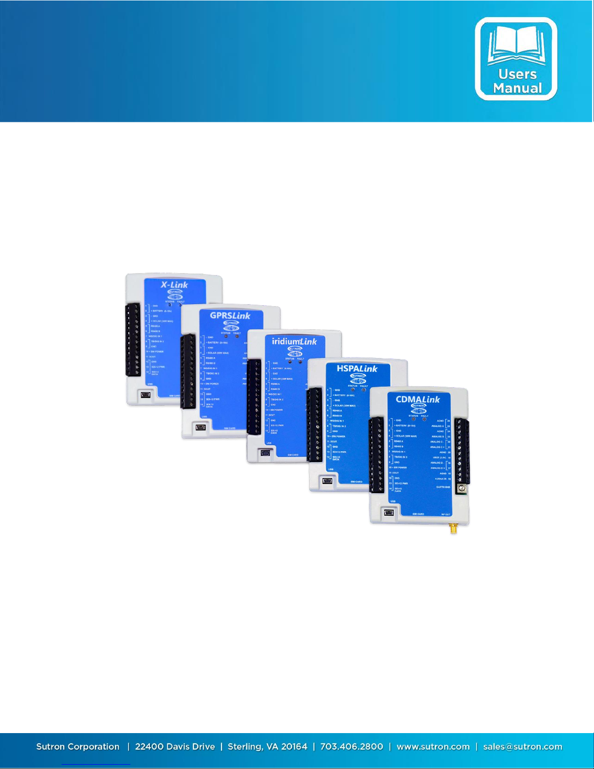
X-Link Data Logger
Operations & Maintenance
Manual
Includes GPRSLink, IRIDIUMLink, HSPALink and CDMALink
Part No. 8800-1190 Rev 1.63
May 24, 2016
Page 2

Sutron Corporation X-Link Operations & Maintenance Manual, Rev 1.63 5/24/2016 pg. 2
TABLE OF CONTENTS
Includes GPRSLink, IRIDIUMLink, HSPALink and CDMALink ............................................ 1
1. Introduction ............................................................................................................... 5
1.1. Models .................................................................................................................. 6
1.2. Applications ......................................................................................................... 6
1.3. Connections .......................................................................................................... 7
1.4. Earth Ground Point............................................................................................... 8
1.5. Input Protection .................................................................................................... 8
1.6. Terminal Strips ..................................................................................................... 8
1.7. Power Connections ............................................................................................. 11
1.8. Wakeup Button ................................................................................................... 14
2. Getting Started ........................................................................................................ 15
3. Measurements ......................................................................................................... 18
3.1. Sensors ............................................................................................................... 18
3.2. Inputs Available ................................................................................................. 18
4. LinkComm ............................................................................................................... 20
4.1. Stations List View – Getting Connected ............................................................ 20
4.2. Station View – Connected or Working Offline .................................................. 26
4.3. Dashboard Tab ................................................................................................... 32
4.4. Measurements Tab ............................................................................................. 34
4.5. Data Tab ............................................................................................................. 37
4.6. Telemetry Tab .................................................................................................... 38
4.7. Other Setup ......................................................................................................... 40
4.8. Diagnostics Tab .................................................................................................. 41
4.9. LinkComm for Phones and Tablets .................................................................... 46
5. Telemetry ................................................................................................................. 48
5.2. Retransmissions .................................................................................................. 50
5.3. Cell Phone Telemetry ......................................................................................... 51
5.4. Iridium Telemetry .............................................................................................. 56
5.5. Sending Messages to X-Link ............................................................................. 57
5.6. Telemetry Status ................................................................................................. 59
5.7. Message Check ................................................................................................... 61
5.8. Optimizing Data Usage ...................................................................................... 62
5.9. Transmissions and Measurements Coinciding ................................................... 63
6. Alarms ...................................................................................................................... 64
7. Setup ......................................................................................................................... 68
7.1. Measurement Setup ............................................................................................ 68
7.2. Telemetry Setup ................................................................................................. 92
7.3. Other Setup ......................................................................................................... 98
8. Measurement Setup Examples............................................................................. 100
8.1. RM Young Wind Speed and Direction ............................................................ 100
8.2. Thermistor ........................................................................................................ 101
8.3. Pressure Transducer (Analog Bridge Sensor) .................................................. 102
8.4. Thermocouple Sensor ....................................................................................... 104
8.5. Tipping Bucket ................................................................................................. 105
Page 3

Sutron Corporation X-Link Operations & Maintenance Manual, Rev 1.63 5/24/2016 pg. 3
8.6. Solar Radiation Sensor ..................................................................................... 106
8.7. SDI-12 Multi-Parameter Sensor ....................................................................... 107
8.8. ISCO Sampler triggering based on Stage ......................................................... 108
8.9. Seametrics Flow Meter..................................................................................... 109
8.10. Computing Rate of Change .............................................................................. 112
9. Logging................................................................................................................... 114
9.2. Log Events........................................................................................................ 115
10. Password ................................................................................................................ 119
10.1. Creating a Password ......................................................................................... 119
11. Output .................................................................................................................... 120
11.1. Output Hardware .............................................................................................. 121
12. Time Keeping ........................................................................................................ 123
12.1. Iridium .............................................................................................................. 123
12.2. SDI Clock Synchronization .............................................................................. 124
13. Errors ..................................................................................................................... 125
13.1. Clearing Errors ................................................................................................. 125
13.2. Measurement Errors ......................................................................................... 125
13.3. System Errors ................................................................................................... 126
14. Command Line Interface ..................................................................................... 128
14.1. Why Use Command Line? ............................................................................... 128
14.2. About the Command Line Interface ................................................................. 128
14.3. Sending Messages ............................................................................................ 129
14.4. Status ................................................................................................................ 130
14.5. Setup ................................................................................................................. 130
14.6. Measurements................................................................................................... 132
14.7. Recording ......................................................................................................... 133
14.8. Downloading the Log ....................................................................................... 133
14.9. Examples .......................................................................................................... 134
14.10. Machine-to-Machine Communication ............................................................. 135
14.11. Auto Output ...................................................................................................... 135
14.12. Command Reference ........................................................................................ 135
14.13. Upgrading Firmware ........................................................................................ 139
15. Collecting Data ...................................................................................................... 141
15.1. Understand Your Selected Communications Method ...................................... 141
15.2. Decide where You Want the Data to Be Transmitted ...................................... 144
15.3. Estimate Communications Costs ...................................................................... 145
15.4. Sign the Agreement .......................................................................................... 148
15.5. Place the Order ................................................................................................. 149
15.6. Ordering Information ....................................................................................... 149
16. Data Formats ......................................................................................................... 153
16.1. TCP/IP Session ................................................................................................. 153
16.2. Iridium Telemetry Header ................................................................................ 154
16.3. Pseudobinary B Data Format ........................................................................... 156
16.4. Pseudobinary C Data Format ........................................................................... 157
16.5. Pseudobinary D Data Format ........................................................................... 159
16.6. Six Bit Binary Encoded Format ....................................................................... 161
Page 4

Sutron Corporation X-Link Operations & Maintenance Manual, Rev 1.63 5/24/2016 pg. 4
16.7. Pseudobinary over SMS ................................................................................... 163
16.8. SHEF and SHEFFIX Data Format ................................................................... 163
16.9. Sutron Standard CSV ....................................................................................... 165
17. More about SDI-12 ............................................................................................... 166
17.1. Overview .......................................................................................................... 166
17.2. Wiring Guidelines ............................................................................................ 167
17.3. Connector ......................................................................................................... 167
17.4. Setup of SDI sensors ........................................................................................ 167
17.5. Useful SDI commands ..................................................................................... 168
18. Modbus................................................................................................................... 169
18.1. Modbus Hardware Interface ............................................................................. 169
18.2. Modbus Setup ................................................................................................... 170
18.3. Modbus Function Codes................................................................................... 172
18.4. Sutron Function Codes ..................................................................................... 174
19. Appendix A – Specifications ................................................................................ 181
20. Appendix B – Sutron Customer Service Policy .................................................. 184
21. Appendix C – Commercial Warranty ................................................................. 185
21.1. Sutron Manufactured Equipment ..................................................................... 185
21.2. Non-Sutron Manufactured Equipment ............................................................. 185
21.3. Repair and Return Policy ................................................................................. 186
22. Appendix D – Installation .................................................................................... 187
22.1. Physical Mounting............................................................................................ 187
22.2. Power Budget Calculations .............................................................................. 188
22.3. Cabling Precautions.......................................................................................... 189
22.4. Antenna Mounting Details ............................................................................... 190
23. Index ....................................................................................................................... 191
Page 5

Sutron Corporation X-Link Operations & Maintenance Manual, Rev 1.63 5/24/2016 pg. 5
1. Introduction
The X-Link family of products provides simple telemetry anywhere. X-Link has
two purposes:
To collect and store data from meteorological and hydrological sensors.
To send that data wirelessly to a central system, phone or other station.
IRIDIUMLink, GPRSLink, HSPALink and CDMALink are members of the X-Link
family of products.
The only difference between the products is in the built-in communications
package:
X-Link basic unit that includes all the measurements and logging capability of
X-Link family but with no modem installed.
IRIDIUMLink includes a transmitter that can deliver data to you from
anywhere in the world via the Iridium satellite constellation.
GPRSLink includes a quad band GSM cell phone modem that can operate
when the unit is within range of a cell phone network of companies like AT&T
and T-Mobile.
HSPALink includes a quad band GSM cell phone modem that can operate at
4G speeds on cell phone networks of companies like AT&T and T-Mobile.
CDMALink includes a CMDA cell phone modem that uses networks of
companies like Sprint and Verizon.
Each X-Link has the same sensor connectors and is capable of making the same
sensor measurements. Up to 16 independent measurements can be set up to
collect data via SDI-12, analog, and digital interfaces.
LinkComm software is used to easily set up and maintain X-Link either via a
direct USB connection or remotely over cell, satellite, or Wi-Fi. LinkComm runs
on Windows PC, OS X, iPhone/iPad, and Android platforms.
X-Link was built to work with Sutron WIN. Sutron WIN makes it easy to collect
data from multiple stations over different communication networks. Sutron WIN
makes it possible to view all your data using a web browser.
Page 6
Sutron Corporation X-Link Operations & Maintenance Manual, Rev 1.63 5/24/2016 pg. 6
Model
Description
X-Link-1
Basic unit with no modem, provides measurement and data logging
capability
X-Link-1E
Basic unit in NEMA-4 box with no modem
IRIDIUMLink-1
Basic IRIDIUMLink unit
IRIDIUMLink-1C
IRIDIUMLink-1 in a NEMA-4 box with battery and internal antenna
IRIDIUMLink-1E
IRIDIUMLink-1 in a NEMA-4 box with connector for external antenna
IRIDIUMLink-1L
IRIDIUMLink-1 in a NEMA-4 box with connector for external antenna with a
antenna lightning arrestor
GPRSLink-1
Basic GPRSLink for operation on GSM networks such as T-Mobile, AT&T,
most all International service providers.
GPRSLink-1C
GPRSLink-1 in a NEMA-4 box with battery and internal antenna
GPRSLink-1E
GPRSLink-1 in a NEMA-4 box with connector for external antenna
GPRSLink-1L
GPRSLink-1 in a NEMA-4 box with connector for external antenna with a
antenna lightning arrestor
HSPALink-1
Basic HSPALink for operation on GSM networks such as T-Mobile, AT&T,
most all International service providers. Allows for 4G speeds.
HSPALink-1C
HSPALink-1 in a NEMA-4 box with battery and internal antenna
HSPALink-1E
HSPALink-1 in a NEMA-4 box with connector for external antenna
HSPALink-1L
HSPALink-1 in a NEMA-4 box with connector for external antenna with a
antenna lightning arrestor
CMDALink-1
Basic CDMALink for operation on Verizon and Sprint networks
CDMALink-1C
CDMALink-1 in a NEMA-4 box with battery and internal antenna
CDMALink-1E
CDMALink-1 in a NEMA-4 box with connector for external antenna
CDMALink-1L
CDMALink-1 in a NEMA-4 box with connector for external antenna with a
antenna lightning arrestor
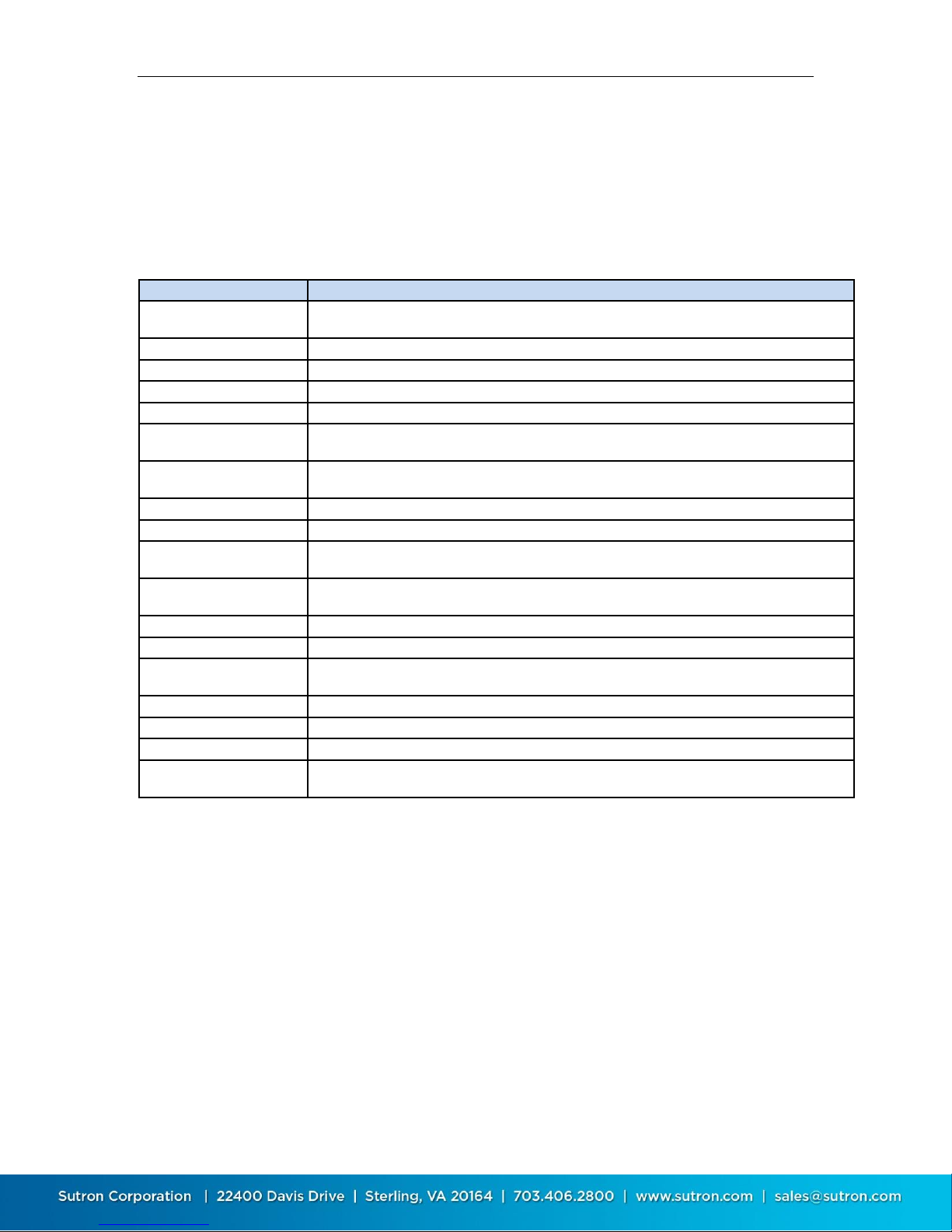
1.1. Models
X-Link comes in several versions to meet varied customer needs. The table below
shows the models currently offered. Check with Sutron for additional models or
for a customized version of X-Link.
1.2. Applications
X-Link products are designed to operate in a wide range of applications
including:
Surface water level, flow and quality
Groundwater level and quality
Offshore monitoring
Mining / geotechnical
Weather monitoring and warning
Oceanic monitoring and warning
Oil and gas production
Any low-power, remote data acquisition system
Page 7

Sutron Corporation X-Link Operations & Maintenance Manual, Rev 1.63 5/24/2016 pg. 7
1.3. Connections
1.3.1. USB Connector
X-Link products come with a mini USB connector for connection to the USB port
on a computer. X-Link uses the USB port for serial data communication only.
Memory sticks are not supported.
LinkComm software is used to talk to an X-Link over the USB cable. LinkComm
can use USB on both Windows PCs and Mac OS X. LinkComm software ships with
every X-Link. However, the latest version is always available from
http://www.sutron.com/downloads.htm (search on “LinkComm”).
Virtual COM Port drivers created by FTDI are included with LinkComm software.
The drivers for Windows PCs are named “CDM v2.0.8.30 WHQL Certified.exe”.
The drivers for OS X (v10.9+) are named “FTDIUSBSerialDriver_v2_3.dmg”.
Please install the drivers before connecting X-Link to your PC.
Some Windows PCs are able to install the drivers automatically but only if the PC
is connected to the internet. If the PC is not connected to the internet, and XLink is connected to the PC before the drivers are installed, LinkComm may not
be able to communicate with X-Link. In that case, please install the provided
drivers and connect X-Link to a different USB port. For further help with the
drivers, please visit the FTDI website.
You will not be able to talk to X-Link without a successful installation of this
driver.
The USB connector is not compatible with USB memory sticks or the USB
connection on a smart phone or PDA.
Page 8
Sutron Corporation X-Link Operations & Maintenance Manual, Rev 1.63 5/24/2016 pg. 8
1.4. Earth Ground Point
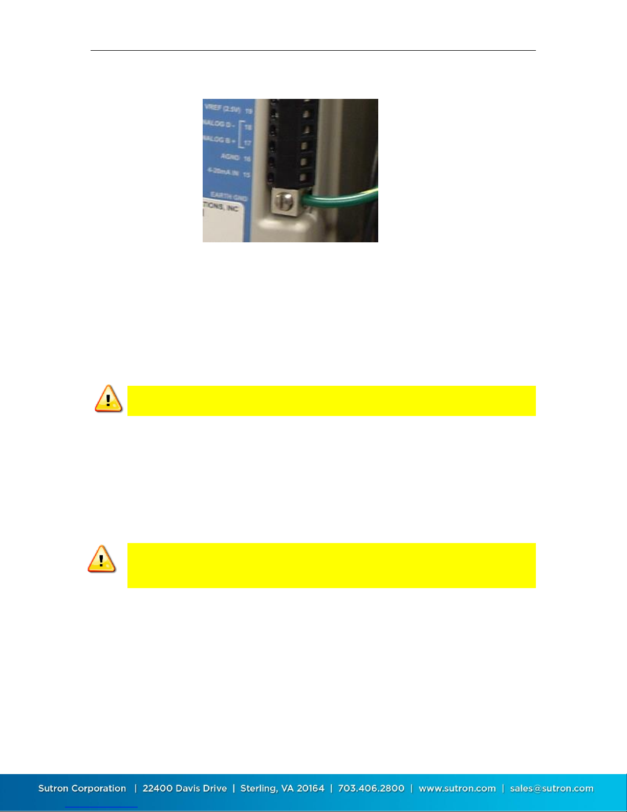
A connection point has been provided for an Earth ground point. This critical
connection always should be made first and should never be overlooked.
Any time a sensor cable is attached to the terminal strip, exposure to dangerous
electrical surges is possible. There are many possible causes, but the most
common source of a surge is created from nearby lightning strikes. Protection is
afforded only when the earth ground is properly connected to a qualified ground
source.
Failure to properly connect the Earth ground point will lead to failures in the
field due to surges.
To install a proper ground connection point:
1. Use a copper ground rod driven into the ground at least 6 feet.
2. Attach a very heavy gauge (#4 Solid Copper) wire between the rod and the X-
Link Earth ground point. The connection point can accept up to a 4 gauge
solid copper wire. If a heavier gauge copper wire is used to connect to the
ground rod, a reducer may be necessary to connect to the terminal on X-Link.
Firmly secure the screw on the ground point firmly on the copper wire. Do not
rely on AC power ground connections as they are not always properly
grounded and may introduce other surges.
1.5. Input Protection
X-Link features gas tube protection on all sensor inputs.
1.6. Terminal Strips
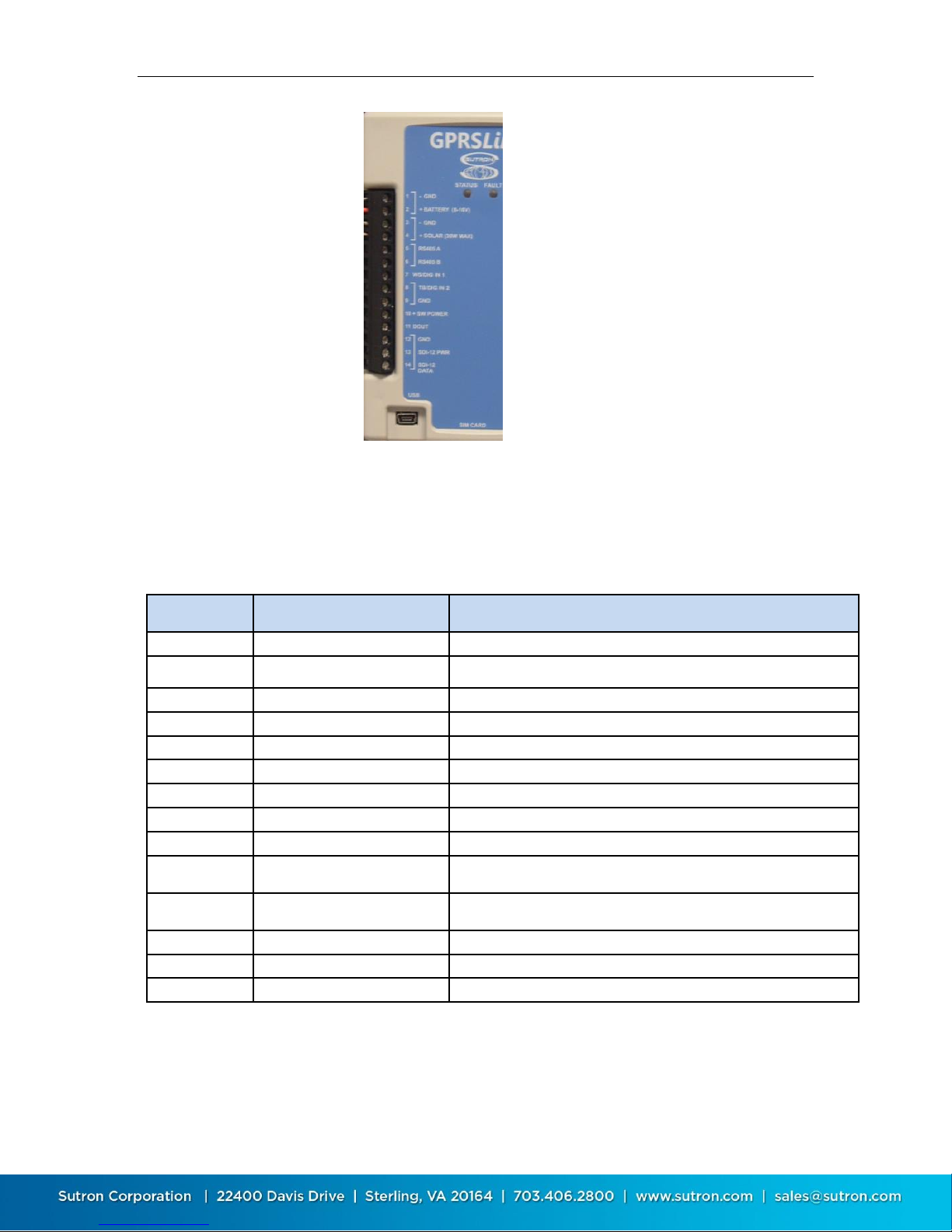
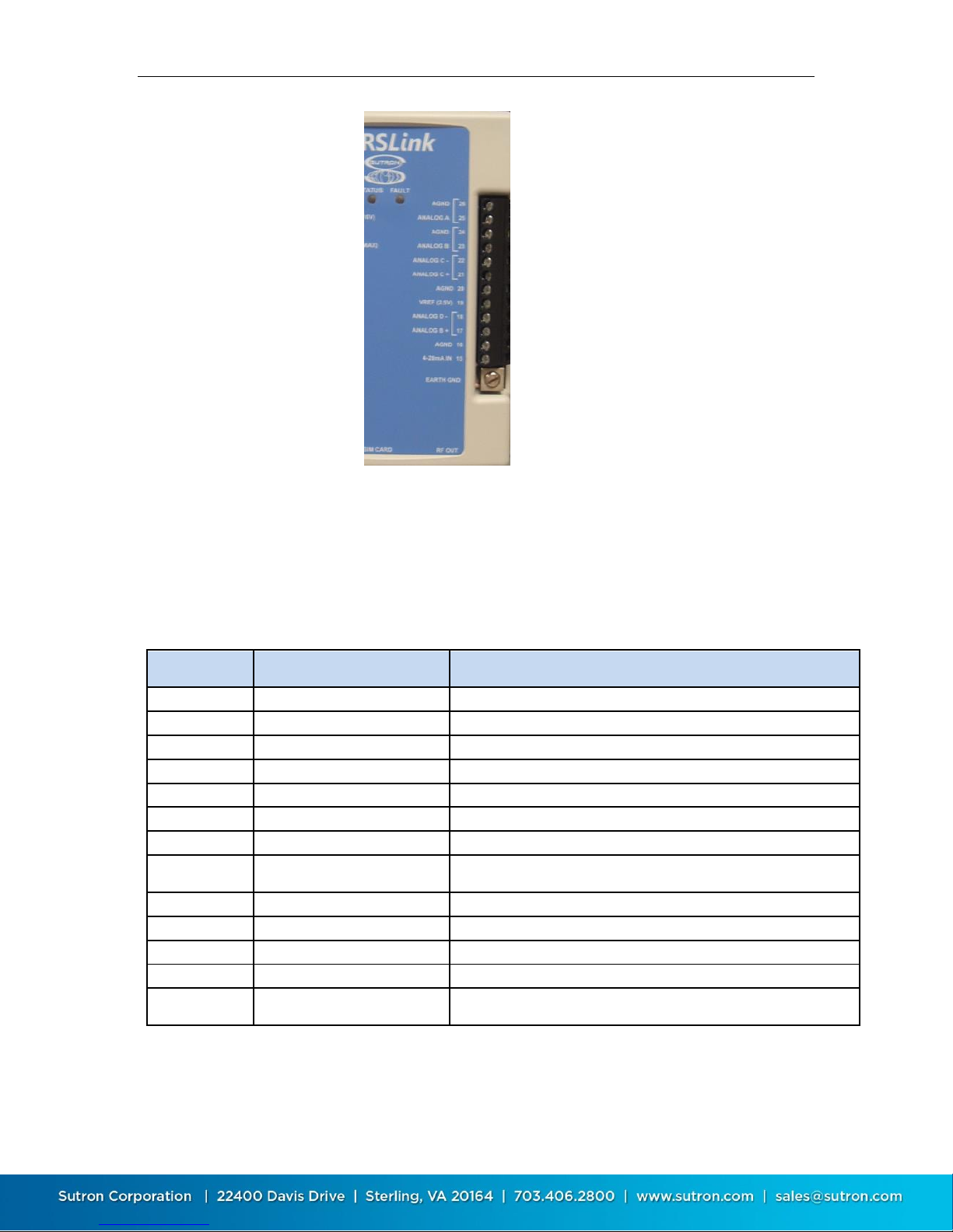
The two terminal strips built into X-Link provide the connections for battery,
solar panel, sensors, and outputs. The table below describes the purpose of each
connection. Additional information on using the connections follows.
Page 9
Sutron Corporation X-Link Operations & Maintenance Manual, Rev 1.63 5/24/2016 pg. 9
Terminal
Block
Description
Notes
1
GND
Main Battery/Power -
2
+ BATTERY (8-16V)
Main Battery/Power +
3
GND
Solar Panel -
4
+ SOLAR (30W MAX)
Solar Panel +
5
RS485 A
SDI-12 over RS-485, Modbus slave
6
RS485 B
SDI-12 over RS-485, Modbus slave
7
WS/DIG IN1
Wind Speed or Digital Input 1
8
TB/DIG IN 2
Tipping Bucket or Digital Input 2
9
GND
Ground for sensor
10
+SW POWER
Switched Power (turned on during warm-up and analog
sensor measurement)
11
DOUT
Digital Output (open collector, turned on manually, with
alarms, or via equations)
12
GND
Ground for SDI-12
13
SDI-12 PWR
Power to SDI-12 sensors (500 ma max)
14
SDI-12 DATA
SDI-12 Data
Page 10
Sutron Corporation X-Link Operations & Maintenance Manual, Rev 1.63 5/24/2016 pg. 10
Terminal
Block
Description
Notes
26
AGND
Analog ground
25
Analog 0-5V ‘A’
Voltage input for sensors with 0-5V output
24
AGND
Analog ground
23
Analog 0-5V ‘B’
Voltage input for sensors with 0-5V output
22
DIFF ‘C’ (- )
Differential voltage input for bridge type sensors
21
DIFF ‘C’ (+)
Differential voltage input for bridge type sensors
20
AGND
Analog ground
19
VREF
2.5V output (turned on during warm-up and analog
sensor measurement)
18
DIFF ‘D’ (- )
Differential voltage input for bridge type sensors
17
DIFF ‘D’ (+)
Differential voltage input for bridge type sensors
16
AGND
Analog ground
15
4-20ma IN
Input for 4-20ma sensor
Earth GND
Earth Ground
Attach via a heavy gauge (4 to 10 AWG) wire to earth
ground rod driven 6 feet into earth.
Page 11
Sutron Corporation X-Link Operations & Maintenance Manual, Rev 1.63 5/24/2016 pg. 11
1.7. Power Connections
1.7.1.1. Battery
X-Link requires an external +12V power source to operate. The most common
power source is a lead-acid or gel cell type battery.
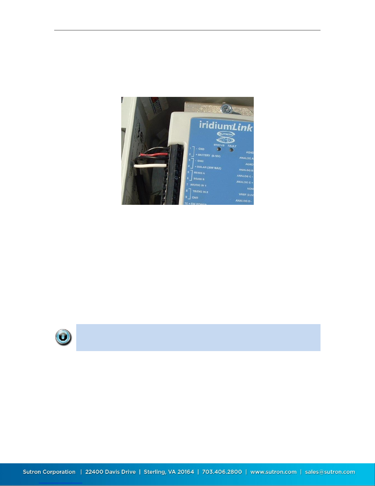
In the figure above, the battery and solar panel are shown connected
Connect the battery to terminals #1 and #2 labeled - GND and + Battery (8-16V)
on the external terminal strip.
The acceptable voltage range for X-Link to operate correctly is 8 to 16 volts. The
capacity of the battery shall be chosen to support the overall station power
budget reflecting the type of sensors, how often they are measured, and desired
length of operation without solar power input. Typical small stations reading a
few sensors once per hour will find the 4 AHr battery sufficient. Power hungry
sensors and aggressive measurement schedules will require larger batteries and
or larger solar panels.
If a SDI-12 sensor is used, a minimum of 10V may be required.
The use of 4-20ma sensors may also necessitate using a battery of 12V
minimum. Consult the sensor manual for requirements.
1.7.1.2. Solar Panel
X-Link features a built-in solar power regulator capable of handling up to 30
watts. Connect the solar panel to terminals #3 Solar Panel - and #4 Solar Panel +.
See figure above for connection details.
Page 12

Sutron Corporation X-Link Operations & Maintenance Manual, Rev 1.63 5/24/2016 pg. 12
The solar panel input with sufficient sun illuminating the panel will power the
station in situations where the battery needs to be removed from the circuit
momentarily for replacement. Long term operation without the battery
connected is not recommended and transmissions via internal Iridium or Cellular
modems may not be possible due to the regulator not being capable of supplying
the necessary current during transmissions.
o The battery will get charged via the solar power connector.
o The solar input will handle voltages from 16 to 22 Volts DC.
o You may connect a power source other than a solar panel (e.g. a power
supply) as long as it conforms to the voltage specification above. Please
note that a battery is still required for long term operation and to ensure
enough current is available for reliable transmissions.
Typical stations with few sensors measuring infrequently may find a 2W or 5W
panel sufficient while stations with more frequent measurements will require a
larger 10 Watt or larger panel.
The internal solar panel charger is designed to output up to 1.5 Amps when peak
charging conditions from a solar panel are present. The Maximum battery size
recommended for this charger is a 4AHr gel cell battery. If the station requires
larger battery sizes, Sutron recommends using an external solar charger
regulator such as the Sutron model 5100-0411 or similar.
Assistance in calculating power budgets may be found here:
http://www.sutron.com/customerservice/Conversions_Calcuations/PowerBudget.htm
1.7.2. SDI-12 Connections
SDI-12 sensors connect to terminals #12, #13 and #14 labeled as GND, SDI-12
PWR and SDI-12 Data. Because SDI-12 sensors are addressable, multiple SDI-12
sensors may connected to these terminals. (See page 78.)
1.7.3. Tipping Bucket Connection
The tipping bucket connection is #8, labeled TB/DIN IN 2, and #9, labeled GND.
This input is compatible with a dry contact switch common to most tipping
buckets. In most circumstances it doesn’t matter which side of the switch is
connected to TB/DIN IN and GND. (See page 105.)
1.7.4. Wind Speed Connection
The wind speed connection is #7, labeled WS/DIG IN 1. This input is compatible
with wind sensors with a 0-5 volt frequency output. Typically, the sensor will also
Page 13

Sutron Corporation X-Link Operations & Maintenance Manual, Rev 1.63 5/24/2016 pg. 13
be connected to #10, + SW Power and #9 GND. For measurement setup, see the
wind speed section. (See page 100.)
1.7.5. Digital Inputs
WS/DIG IN 1 and TB/DIG IN 2 are also general purpose digital inputs capable of
making counter, frequency, period, or level measurements. The maximum
frequency of any digital input is 10Khz.
1.7.6. Analog Connections
The terminal has connections for five analog inputs.
The inputs labeled Analog A and Analog B are for 0-5V sensors.
The inputs labeled Analog C, and Analog D support +/-39mv, +/-312mV or +/-
2.5V sensors.
There is a separate connection for 4-20ma sensors.
Detailed notes describing how to connect sensors to the terminal blocks are
provided in the Setup section of this manual, beginning on page 68.
1.7.7. RS-485
X-Link can use the RS-485 connection in two ways: SDI-12 and Modbus.
1.7.7.1. Modbus over RS-485
X-Link can function as a Modbus slave. In this mode, it can provide
measurement results, log file access, and more. Please see page 169 for details.
1.7.7.2. SDI-12 over RS-485
Sutron products such as the CF Bubbler support this connection. SDI-12 over RS485 is generally used to allow longer cable lengths.
RS-485 does NOT provide power to the sensor. Do not forget to provide
appropriate power to the sensor!
1.7.8. Outputs
The following output capability exists in the X-Link product.
1.7.8.1. Digital Output
On Terminal #11 is the digital output (DOUT). It is an open collector switch. The
switch can be turned on and off manually (by issuing a command via LinkComm
or via a cellular, satellite, or Wi-Fi message), it can be turned on when the station
goes into alarms.
1.7.8.2. Switched Power
Terminal #10 is the switched battery output. It is labeled +SW POWER.
Page 14

Sutron Corporation X-Link Operations & Maintenance Manual, Rev 1.63 5/24/2016 pg. 14
This line will output a voltage during the warmup for the following measurement
types: analog, SDI-12, and digital. It will also always turn on when an analog
measurement is made.
This line will output whatever voltage is powering X-Link on the battery terminal.
1.7.8.3. VREF
Terminal #19 outputs a 2.5 V reference during the warmup for an analog sensor
and when an analog measurement is made.
1.8. Wakeup Button
X-Link models manufactured in 2013 or later have a wakeup button on the top
right side of the box.
Pushing the button will have X-Link turn on its Wi-Fi chip and modem. When
visiting a field station, push the button, then use your mobile phone or tablet to
connect to X-Link via Wi-Fi.
When the button is pushed, the green LED will light up for a few seconds,
indicating that Wi-Fi is now on.
If the button is held down for 5 seconds, the red LED will come on too. Keep
holding the button until the red LED turns off in order to reboot X-Link.
Page 15

Sutron Corporation X-Link Operations & Maintenance Manual, Rev 1.63 5/24/2016 pg. 15
2. Getting Started
Follow these steps to become familiar with X-Link.
1. Connect power to pins 1 and 2 as shown on page 11. A 9V battery will work
fine for short-term testing without transmitting. For longer operation or if
testing with a SDI-12 sensor, connect a larger battery or power supply.
Typical applications use a 4AH or 7AH battery with a 5 to 10 watt solar panel.
2. As soon as power is applied, the LED will flash, first rapidly and then every
several seconds. This indicates the X-Link is operating.
3. Download the LinkComm program. Go to
http://www.sutron.com/downloads.htm, search on “LinkComm”, and
download the installation package for your operating system, e.g.,
“Windows”, “OSX”, or “Android” (for “iOS”, please use App Store on your
mobile device)
o For Windows, extract all files to a folder on your computer. You may run
LinkComm directly from this folder by double-clicking “LinkComm.exe”,
or, to install LinkComm so that it appears on the Start menu, double-click
“setup.exe” (Administrator privileges are required to install LinkComm)
o For OSX, mount the downloaded disk image, and copy the LinkComm
application bundle to your “Applications” folder
o The download package contains all required software including
LinkComm, X-Link upgrade files, USB drivers, and the user manual
4. Connect the USB cable from your computer to X-Link. If the computer does
not automatically install the FTDI USB-to-serial drivers for you, install them
manually.
a. On Windows, if you installed LinkComm, then simply select Install X-Link
USB Drivers from the Windows start menu. Or, locate and run
“CDM_v2.08.30 WHQL Certified.exe” in the installation package you
downloaded in the previous step
b. On OSX, locate and run the installer in “FTDIUSBSerialBus_v2_3.dmg”
5. Run LinkComm
Page 16
Sutron Corporation X-Link Operations & Maintenance Manual, Rev 1.63 5/24/2016 pg. 16
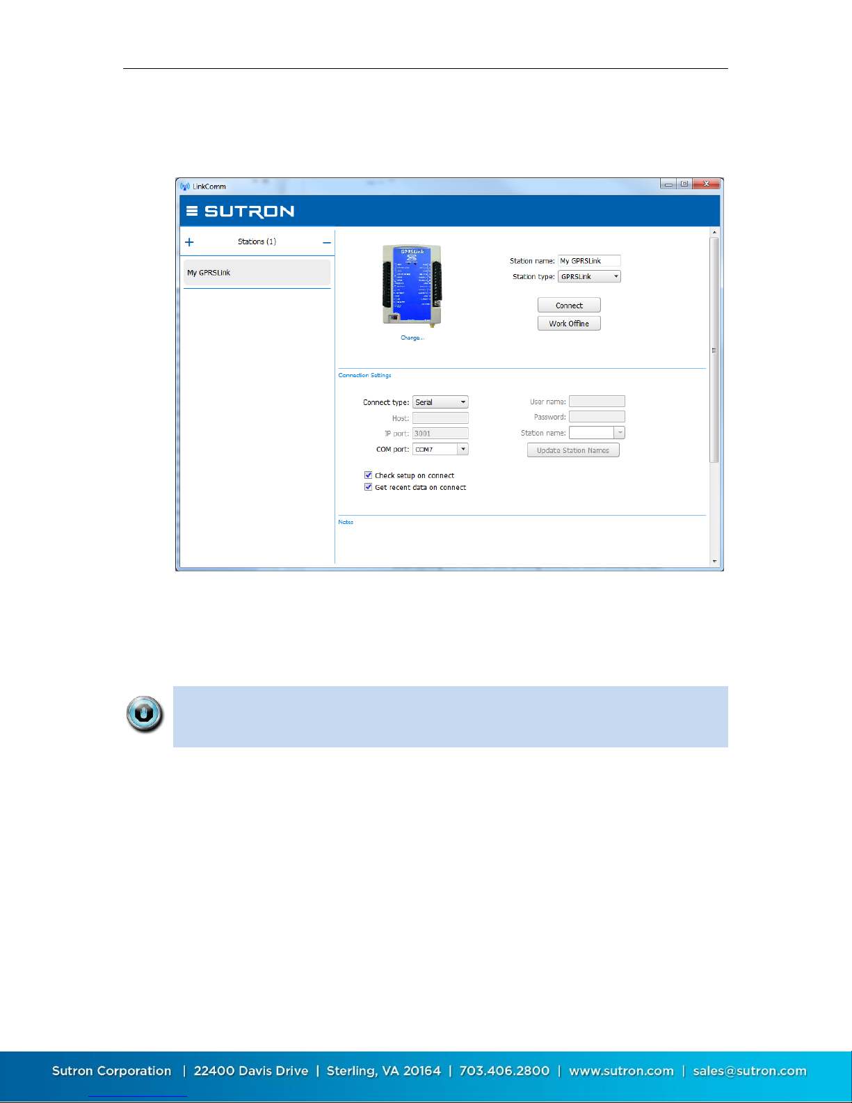
a. In the window that comes up, press “+” to create a new station. Set
“Station type” to match your type of X-Link, set “Connect type” to
“Serial”, and set “COM port” to the port assigned to X-Link
b. Press the “Connect” button to connect to X-Link. LinkComm will connect
to X-Link and download the setup and recent data (if those options are
selected in the station setup, above)
Page 17

Sutron Corporation X-Link Operations & Maintenance Manual, Rev 1.63 5/24/2016 pg. 17
6. Select the Measurements tab. This is where you will set up X-Link to
measure, process, and log data. If the unit is in its factory default condition,
there will be no measurements enabled. To set up measurements, see page
68.
We recommend that you setup and test all measurements before deploying
the station in the field.
7. Select the Telemetry tab. This is where you will set up X-Link to transmit the
data. If the unit is in its factory default condition, there will be no telemetry
enabled. To set up telemetry, see page 92.
We recommend that you setup and test the telemetry setup before deploying
the station in the field.
8. Select the Diagnostics tab. This is where you set the unit to factory defaults
or to use the terminal tool. To set up diagnostics, see page 41.
9. To access the main menu, press the button in the upper left. Use options
on the main menu to send/get setups, start/stop recording, exit the
application, etc.
Page 18

Sutron Corporation X-Link Operations & Maintenance Manual, Rev 1.63 5/24/2016 pg. 18
3. Measurements
A measurement is the process of collecting data from a sensor. X-Link provides
the ability to establish up to 16 measurements, each with its unique setup. Each
measurement will occur periodically and provide one or more results, which are
usually related to weather conditions.
Measurement results may be logged. The log can hold almost 250,000 unique
readings. Logged measurement results may be transmitted via cellular or
satellite modems.
3.1. Sensors
As a data logger, one of X-Link's primary functions is to measure and log data
from sensors. All commonly used environmental sensors are supported.
Here is a list of some of the sensors supported and available through Sutron:
AT/RH (Air temperature and relative humidity) - using analog or SDI-12
sensors
Precipitation – using a tipping bucket
Wind Speed / Wind Direction - RM Young or Gill ultrasonic via frequency,
analog, and SDI-12 inputs (includes vector averaging)
Stage - using SDI-12 shaft encoder, radar level recorder, stage discharge
recorder, analog submersible, bubbler
Barometric Pressure - using an SDI-12 Accubar or a built-in Accubar.
Solar Radiation via differential analog input
3.2. Inputs Available
Each of these inputs can have one sensor connected to it, except for SDI-12,
which can connect to several sensors.
Analog inputs
Two 0-5 V single ended analog inputs
Two differential analog Inputs (for bridge type sensors)
One 4-20mA input
Digital inputs
Two general purpose digital inputs that can be set up as
o Counter digital input (e.g. tipping bucket)
o Frequency/period input (e.g. wind speed)
Page 19

Sutron Corporation X-Link Operations & Maintenance Manual, Rev 1.63 5/24/2016 pg. 19
o Level digital inputs (read line state as 1 or 0)
RS-485
o Support for certain sensors such as the Seametrics flow meter
SDI-12 input
o SDI-12 V1.3 compliant supports multiple sensors all connected to the
same bus
One Accubar connector (internal)
Please see the Measurement Setup section, beginning on page 68, for details on
how to set up a measurement.
Page 20

Sutron Corporation X-Link Operations & Maintenance Manual, Rev 1.63 5/24/2016 pg. 20
4. LinkComm
LinkComm is a software application designed to talk to X-Link. LinkComm is free.
LinkComm is used to:
Check X-Link status
Set up an X-Link station
Download and graph the log from X-Link
Upgrade X-Link firmware
Calibrate connected sensors
…and more...
Download LinkComm from here: http://www.sutron.com/downloads.htm
(search on “LinkComm”).
The PC version is supported on Windows 7 and higher. Operation on Windows
XP is possible so long as a graphics driver is installed that fully supports either
OpenGL v2.1 or DirectX 9.0.
The version for Mac supports OSX 10.x and above.
Mobile versions of LinkComm are also available to run on Apple iPad and iPhone,
and on Google Android phones and tablets. They can be found on the Apple®
App Store™, and Google® Play Store™, respectively. Quick Start Guides that
describe how to use the mobile versions of LinkComm are also available for
download from the link above.
To connect LinkComm to X-Link via USB, the FTDI USB to serial drivers must be
installed. Please see section 2, “Getting Started”, for details on how to get these
installed.
4.1. Stations List View – Getting Connected
LinkComm requires you create a station definition before you can connect to it
or work on its setup. You’ll normally create an entry in the Stations list for every
station you manage on an on-going basis. It’s easy to add and delete station
entries, so you’ll also often create a temporary station entry for ad-hoc
connections.
Page 21
Sutron Corporation X-Link Operations & Maintenance Manual, Rev 1.63 5/24/2016 pg. 21
You use LinkComm’s “Stations List View” (sometimes called “Connect View”) to
perform station management. This is the view you first see when LinkComm
starts up.
To add a new station, press the “+” button in the stations list header. To delete a
station definition, select the station and then press the minus sign in the stations
list header. LinkComm will prompt to make sure you really want to delete the
station, since this action cannot be undone.
Note: All settings (station and connect settings, notes, and site images) for
every station you define are saved automatically as you make changes. Hence,
there is no need to select any kind of “Save” menu item.
4.1.1. Station Settings
The top portion of the Station List View is where you configure station settings
like station type and name. This is also where you’ll find the Connect and Work
Offline buttons.
When setting up a new station, be sure to set “Station type” to the type of X-Link
you’re setting up. Also be sure to set “Station name” to the name you desire for
the station. This name is updated if it differs from the name stored in X-Link
anytime you get the setup from the actual X-Link, though you will be prompted
first regarding the difference, if any.
Page 22
Sutron Corporation X-Link Operations & Maintenance Manual, Rev 1.63 5/24/2016 pg. 22
You can change the picture used for your station definition by selecting the
“Change…” text underneath the picture. The menu that pops-up also gives you
the ability to restore the picture to its default for the station type. If a camera is
available, you also have the option of taking the picture to be used.
Press the “Connect” button to connect to X-Link. When connected, you are able
to see current data values, historical data, and the setup in the unit.
Press the “Work Offline” button if you want to make changes to the setup stored
locally for the station, without connecting to X-Link. When you later connect to
X-Link, LinkComm will notice the setup in the unit is different than the one
stored locally, and will ask you which one to use (LinkComm first asks if you want
to retrieve the setup from X-Link. If you answer “No”, LinkComm then asks you if
you want to send the local setup to X-Link).
4.1.2. Connection Settings
There are several ways to connect to X-Link:
Directly via USB cable
Remotely via TCP/IP
Remotely through the Sutron Redirector
Locally via X-Link’s Wi-Fi
Basic features, such as checking status and changing setup are available via all
connection types. However, some features, such as upgrading the firmware, are
available only over USB. Additionally, changing some of the settings and
disabling the password is not possible remotely.
“Check setup on connect”, when checked, will cause LinkComm to retrieve the
setup from X-Link every time you connect. You may choose to disable this
feature to reduce data costs (e.g., for cellular connections that cost money).
“Get recent data on connect”, when checked, will cause LinkComm to download
the last week of data for display in a graph on the dashboard tab, every time you
Page 23

Sutron Corporation X-Link Operations & Maintenance Manual, Rev 1.63 5/24/2016 pg. 23
connect to X-Link. This can be a considerable amount of data (several k-bytes).
Here again, you may choose to disable this feature to reduce data costs.
4.1.2.1. Connecting via USB
LinkComm can connect directly to X-Link via a USB cable. Simply connect a USB
cable from your computer to X-Link.
USB drivers are included in the LinkComm download package. These drivers are
required to connect to X-Link over USB. Please see Section 2, Getting Started,
for more details on their installation.
Please be sure to follow the instructions in Section 2, “Getting Started”, to
download and run LinkComm, connect it to X-Link, and verify communications
before setting out to the field. Indeed, we recommend that station setup be
completed and tested at the office before deploying the station.
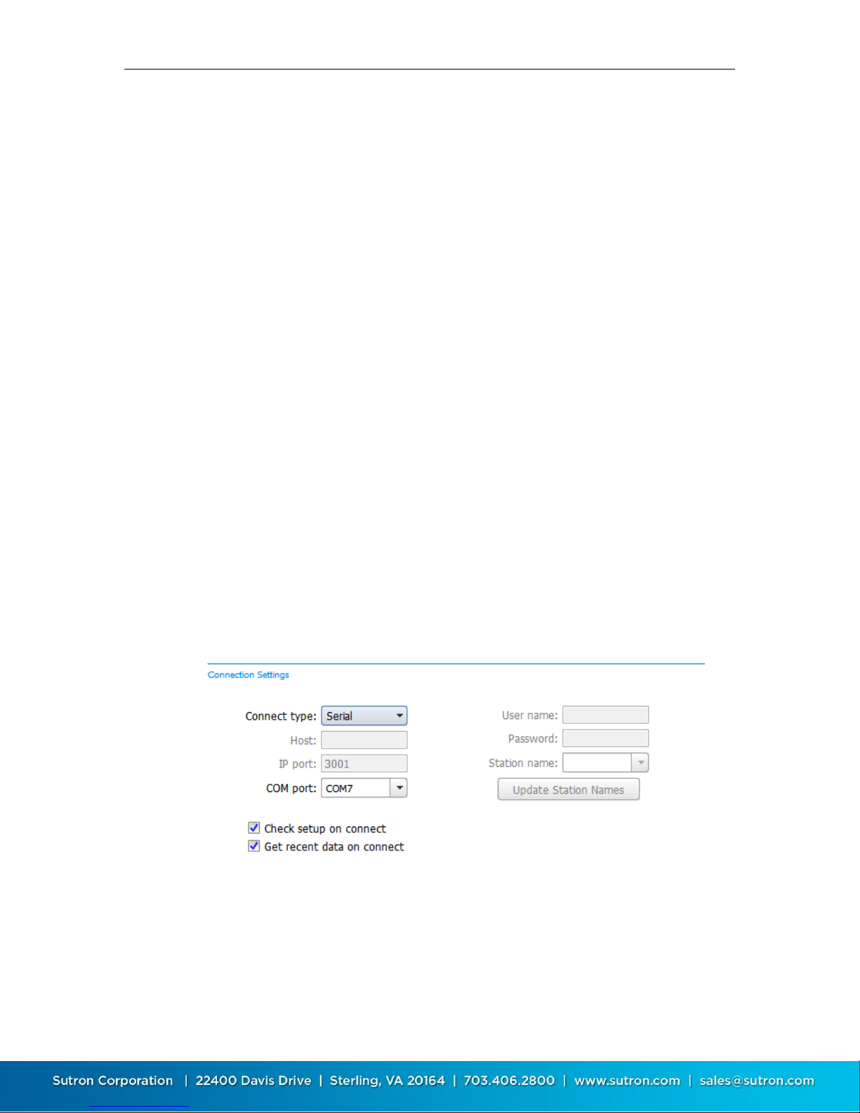
To connect via USB, set “Connect type” to “Serial”, and then set “COM port” to
the port assigned to X-Link by the operating system.
When X-Link is first connected to a USB port, Windows will create a virtual Com
port (e.g. COM5). Each time the cable is connected to a different USB connection,
a new port is created. The port assignment can be confirmed using Windows
Device Manager (Control Panel). If LinkComm does not list the assigned port,
please enter it manually.
4.1.2.2. Connecting Remotely
LinkComm can also talk to a GPRSLink, HSPALink, and CDMALink over the
internet. To do so, GPRSLink, HSPALink, and CDMALink need to have the
Listening setting enabled.
Alternatively, to reduce power consumption, the system can be configured to
check for messages periodically. A message can be sent to the station asking it
to temporarily turn on listening. Please see the Message Check section on page
61 and Sending Messages to X-Link on page 57.
4.1.2.2.1. TCP/IP
If the IP address of an HSPALink, GPRSLink, or CDMALink is known, it can be
connected to directly. It is up to cell service provider to
1. Give a static IP address. This means that the IP address of X-Link does not
change over time. Alternatively, you may send an SMS to the X-Link
asking what its current IP address is.
2. Provide VPN access. It is not always possible to directly connect to X-Link
over the internet because it is protected by the cell service provider’s
Page 24
Sutron Corporation X-Link Operations & Maintenance Manual, Rev 1.63 5/24/2016 pg. 24
firewall. In this case, it is necessary to first connect to a VPN provided by
the cell service provider.
4.1.2.2.2. The Redirector
Sutron provides a “redirector” service that can be used to access a GPRSLink,
HSPALink, or CDMALink station that uses a SIM card provided by Sutron. The IP
addresses of these SIM cards are behind a firewall, and so need special steps to
be taken for access.
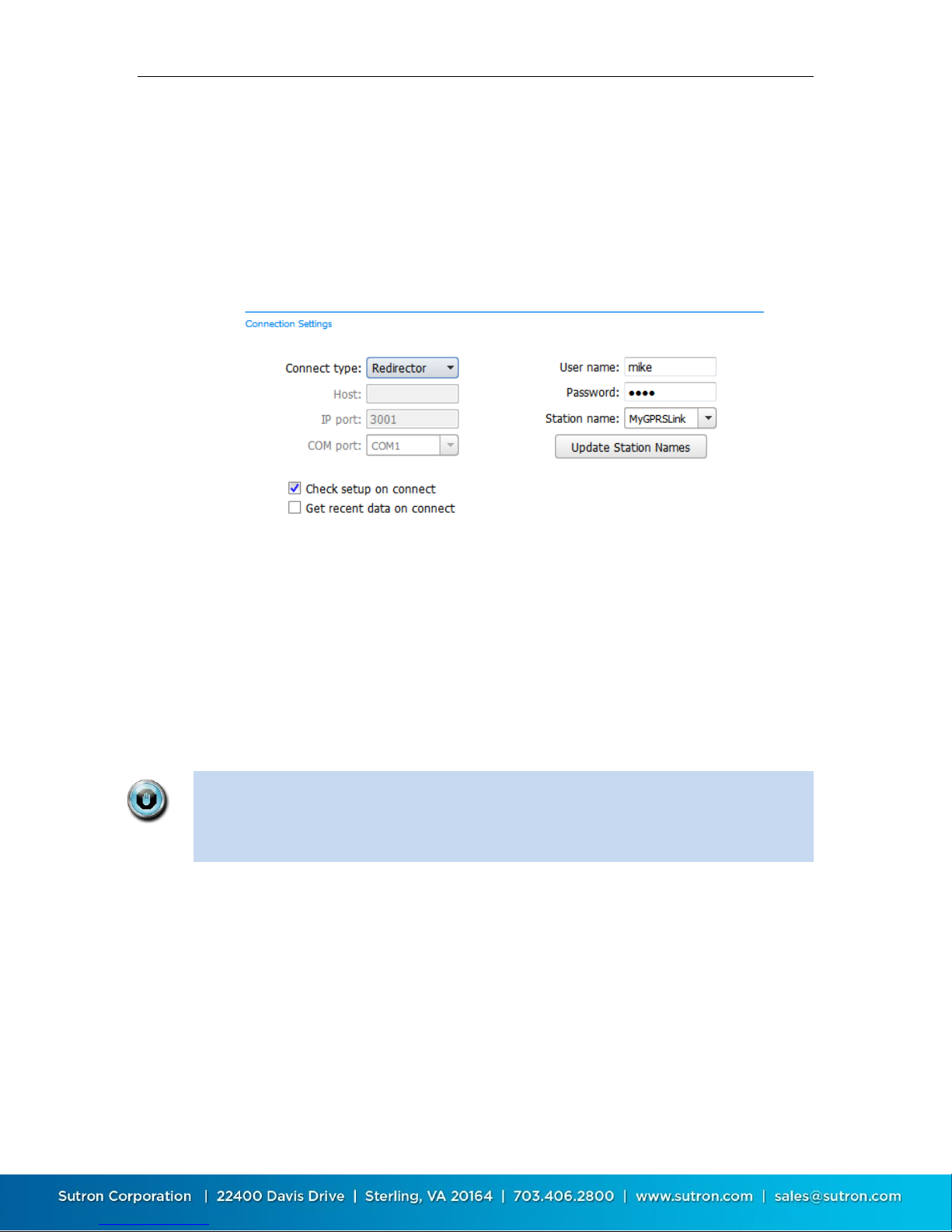
When obtaining one of these SIM cards from Sutron, you will also receive a user
name, password, and station name to use when setting up your station
connection in LinkComm. After entering your user name and password, you may
press the “Update Station Names” button to retrieve the list of stations that are
associated with your redirector account.
4.1.2.2.3. Dropped Connections
Please note that remote connections over cell networks, including those made
over Redirector, are not always the most reliable.
An internet TPC/IP connection to X-Link can get dropped. This can happen after
a timeout or due to a poor connection. If the connection is dropped, reconnect
by pressing the “Connect” button in the header, or by returning to the Stations
List view and pressing the “Connect” button
4.1.2.3. Connecting via Wi-Fi
X-Link can provide a Wi-Fi hotspot that LinkComm can connect to. The Wi-Fi
feature is useful for connecting to X-Link with a mobile phone, tablet, or laptop.
X-Link models manufactured in 2013 or later feature Wi-Fi. These units are
identifiable by the button on the right side of the box.
Page 25

Sutron Corporation X-Link Operations & Maintenance Manual, Rev 1.63 5/24/2016 pg. 25
Wifi
Enable
Wifi Always
On
Result
OFF
-
The Wi-Fi hotspot is off. It is only turned on if the wakeup
button is pressed. It stays on for one hour after the
button press.
ON
ON
The Wi-Fi hotspot is always on.
In order for LinkComm to connect to X-Link via Wi-Fi, the computer that is
running LinkComm must first connect to the Wi-Fi hotspot provided by X-Link.
To connect to X-Link via Wi-Fi, follow this sequence:
1. Have X-Link turn on the Wi-Fi by pushing the wakeup button located on
the right side of X-Link. X-Link will blink the green LED to acknowledge
the button press. Please see below for other ways to turn on Wi-Fi.
2. Have your computer (Laptop, iPhone, or Android) connect to X-Link’s Wi-
Fi hotspot.
a. X-Link will name its hotspot SutronXL_xxxx_aaaa, where xxxx is
the station name and aaaa is a unique number.
3. Create a new station in LinkComm with “Connect type” set to “Station
WiFi” (if LinkComm detects you are connected to an X-Link via WiFi, it will
set this type by default)
a. If you need to manually enter the IP address for X-Link, it is
192.168.88.1:3000.
4. LinkComm is now connected to X-Link. It is possible to check status,
change setup, download log, and perform almost all other operations.
5. Once the LinkComm session is complete, make sure to disconnect from
X-Link's WiFi hotspot.
In order to conserve power, X-Link only turns on the Wi-Fi hot spot at certain
times. There are two settings that control when X-Link turns on the Wi-Fi
hotspot:
Wifi Enable: If this setting is off, X-Link will never turn on it’s Wi-Fi
automatically. Turn Wifi Enable off if there are no plans to connect to XLink via Wi-Fi. Please note that pressing the wakeup button will turn on
the Wi-Fi hotspot even if Wifi Enable is off.
Wifi Always On: if this setting is on, the Wi-Fi spot provided by X-Link will
always be turned on. Turning this setting on will result in increased
power consumption, but it will make X-Link always available to connect
to.
The table below describes when the Wi-Fi hotspot is on.
Page 26

Sutron Corporation X-Link Operations & Maintenance Manual, Rev 1.63 5/24/2016 pg. 26
ON
OFF
The Wi-Fi hotspot is turned on for 10 minutes:
at boot up
when the station is connected to, whether via
USB, over the modem, or over Wi-Fi
after an SMS is received
after a TXLISTEN command.
The Wi-Fi hotspot turns on for one hour when:
The wakeup button is pressed
The station goes into alarm
4.1.3. Notes
This section is typically used to enter notes in this section related to station
setup and maintenance. For example, you might store information about the last
time the station was visited, plans for future visits, and notes on calibrations, etc.
4.1.4. Site Images
This section allows you store pictures of the site. Click “Add New Image” to
browse for images to store. If a camera is available, you’ll have the option to
take pictures to store as new site images.
When you click a site image, it expands to fill the available window.
To delete a site image, right-click (or press-and-hold) the image and select
“Delete Site Image” in the subsequent prompt.
4.1.5. Main Menu While in Stations List View
Press the button in the upper left to access the main menu. When the Station
list view is active, the main menu offers options to:
See “About…” information
Visit the Sutron website
View the LinkComm event log (useful for debugging with customer service)
Exit the app (not present on mobile app)
4.2. Station View – Connected or Working Offline
After you press either “Connect” or “Work Offline” in the stations list view,
LinkComm transitions to the “Station View”, where you see several tabs, e.g.,
Dashboard, Measurements, Data, etc., each showing information about status
and/or setup for the selected X-Link.
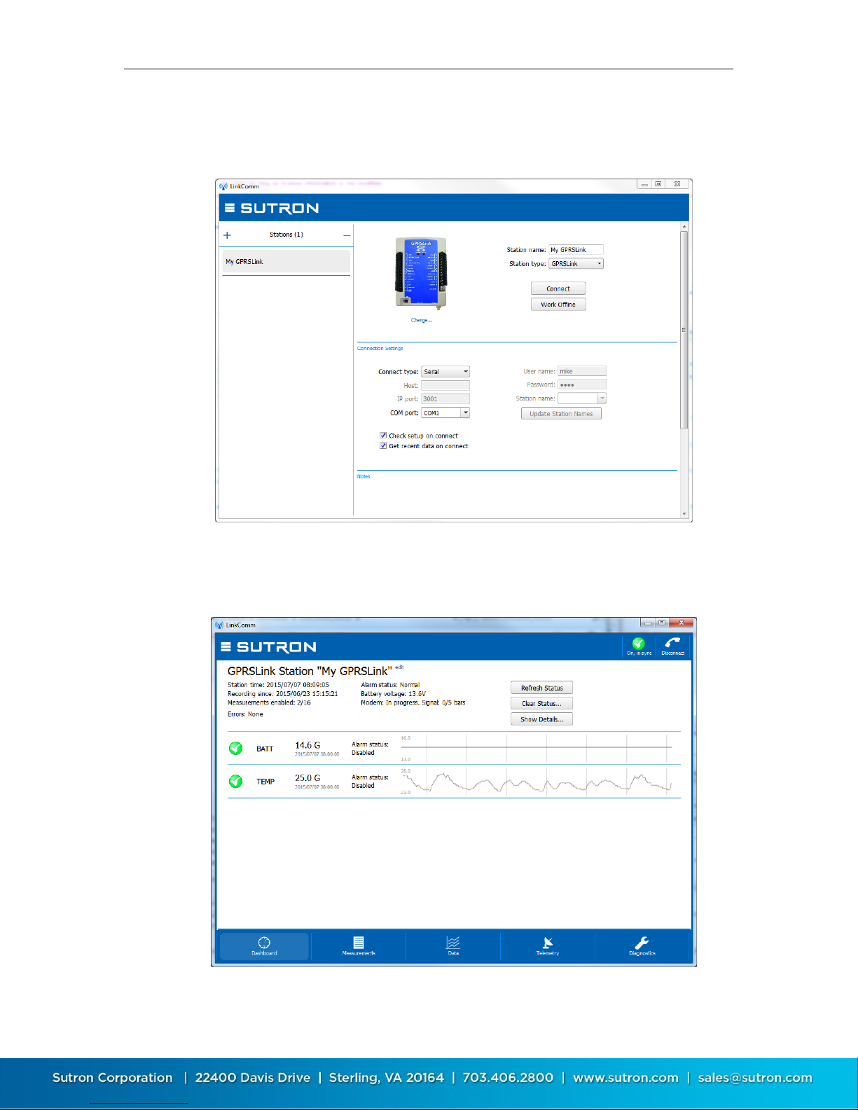
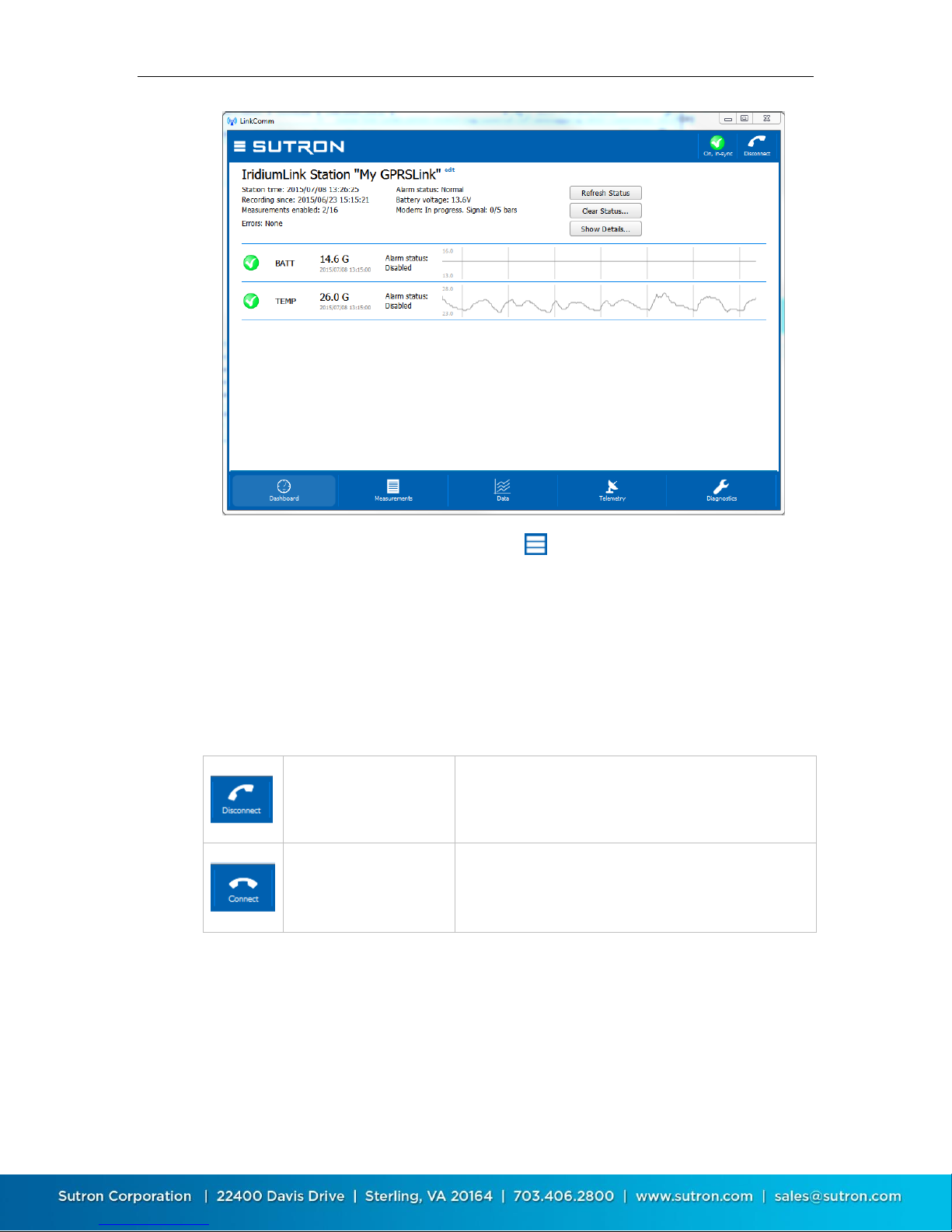
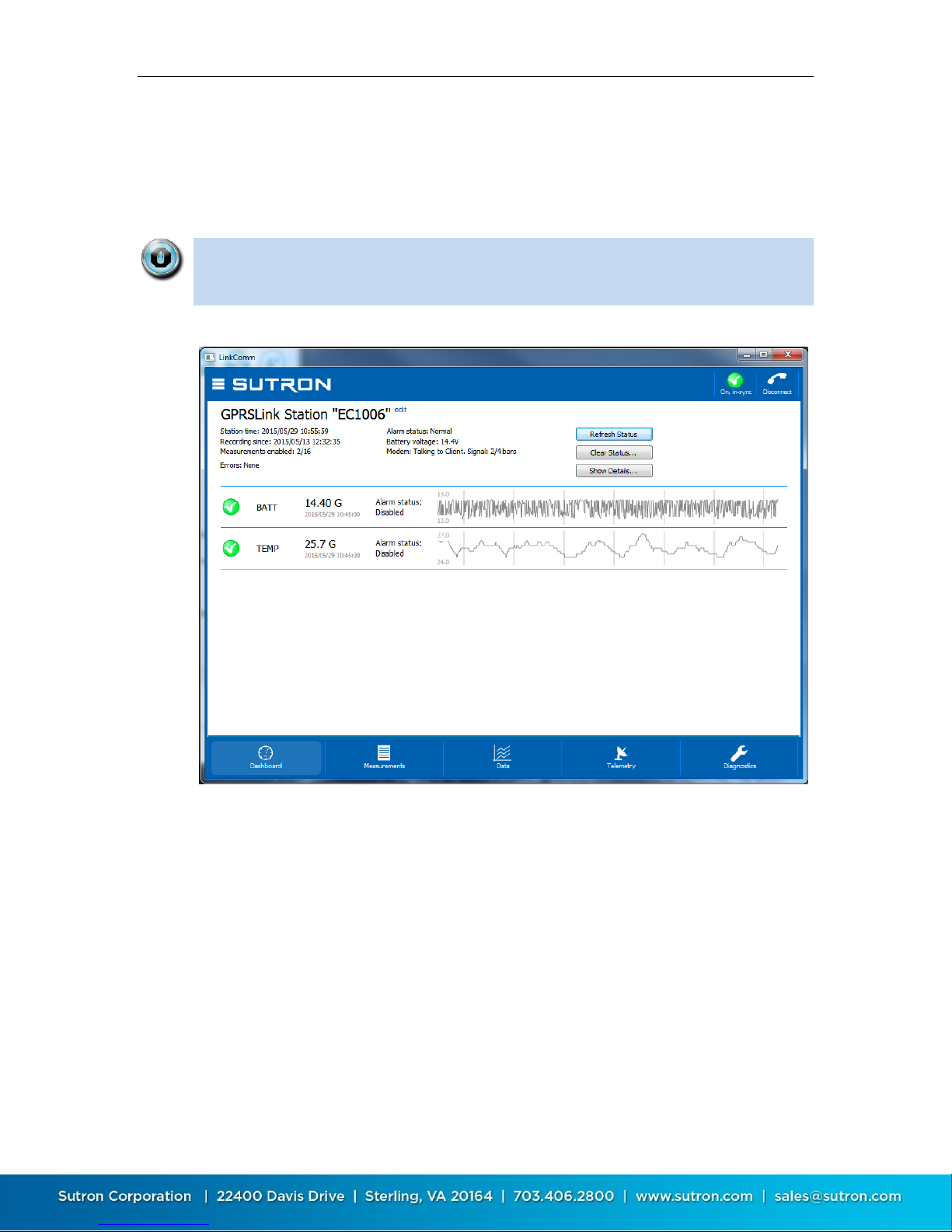
The following picture is of the station view with the Dashboard tab selected:
Page 27
Sutron Corporation X-Link Operations & Maintenance Manual, Rev 1.63 5/24/2016 pg. 27
LinkComm is connected
to X-Link
Pressing the button in this state will cause LinkComm
to disconnect from X-Link
LinkComm is not
connected to X-Link
Pressing the button in this state will cause LinkComm
to try to connect to X-Link
The main menu is accessed by pressing the button in the upper left. Different
tabs are selected by pressing the tab buttons at the bottom of the view. The
station view header contains two important buttons in the upper right,
described next.
4.2.1. Connect Button
The right header button is the “Connect Button”, and shows the status of the
current connection from LinkComm to X-Link. The button has two possible
states:
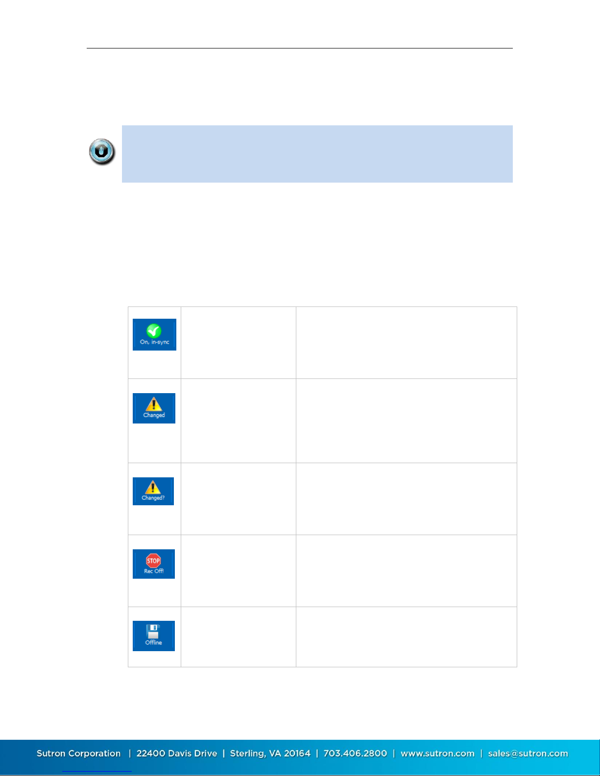
4.2.2. Setup Status Button
The left header button is the “setup status button”. This button shows status
related to the setup, including whether the setup is “in-sync”, i.e., the same in
both LinkComm and X-Link, and recording status.
Page 28
Sutron Corporation X-Link Operations & Maintenance Manual, Rev 1.63 5/24/2016 pg. 28
LinkComm is connected
to X-Link, recording is ON,
and the setups are “insync”
Press the button to turn off recording. LinkComm
will prompt for confirmation.
A change has been made
to the setup in LinkComm
(it no longer matches the
setup in X-Link)
Press the button to send setup changes to X-Link.
LinkComm will prompt for confirmation. If “Yes”,
only the changes required to be “in-sync” are sent. If
“No”, LinkComm prompts to retrieve the setup from
X-Link, overwriting local changes
The setup in X-Link is
unknown, and so may
differ from the one
displayed by LinkComm
Press the button to send the setup to X-Link.
LinkComm will prompt for confirmation. If “Yes”,
LinkComm first sets the setup in X-Link to defaults,
and then sends the changes required to be in-sync
Recording is OFF in X-Link.
This means no
measurements are being
made
Press the button to turn recording ON in X-Link.
LinkComm will prompt for confirmation
LinkComm is working off
line (not connected to XLink)
Press the button to connect to X-Link
Pressing the setup status button typically prompts the user to take the next
logical step towards getting the setup in-sync between LinkComm and X-Link,
with recording on.
Note: When the setup displayed by LinkComm is the same as the setup in XLink, then we say the setups are “in-sync”. When the setups are not the same,
the setup status button displays a warning sign, and you must send the setup
to X-Link to get the setups “in-sync”.
After making changes to the setup locally, you need to send those changes to XLink to bring the setups “in-sync”. You do this by pressing the setup status
button (or by selecting the main menu item, “Send Setup to X-Link”).
The following table describes the different states maintained by the setup status
button, and describes what happens when you press the button in each of the
states:
Page 29
Sutron Corporation X-Link Operations & Maintenance Manual, Rev 1.63 5/24/2016 pg. 29
4.2.3. Working with Setups
Since both LinkComm and X-Link maintain separate setups, working with setups
can be a bit tricky. This section explains how to work with setups in more detail,
so you can be sure X-Link is always running the setup you intend.
An X-Link's setup dictates how it will behave when it is turned on: what sensors
to collect data from, where to transmit data, and so on. LinkComm is used to set
up a station and to manage setup files.
You make changes to the setup using the Measurements and Telemetry tabs
(described in later sections). The station name may be changed using the
Dashboard tab.
LinkComm keeps a copy of the station setup locally. It is this setup that you see
displayed in LinkComm. As you make changes to the setup, it is automatically
saved locally, so there is no need to select a “Save” menu item or button.
However, you do need to send the setup to X-Link.
The setup that is shown in LinkComm is not necessarily the same setup that is
in a connected X-Link
To read a setup from an X-Link and show it in LinkComm, you may either use
the setup status button as described in the previous section, or select the
Get Setup From X-Link item from the main menu
To give a setup created by LinkComm to X-Link, you may either use the setup
status button as described in the previous section, or select the Send Setup
To X-Link item from the main menu
Unless the setup status button menu item is selected, or the Send Setup to XLink button is clicked, none of the changes made to the setup in LinkComm will
be in X-Link!
4.2.3.1. Getting Started with Setup
When you create a station definition in LinkComm, the local setup is empty. If
you then connect to X-Link and get the setup, the setup in X-Link becomes the
new local setup, no questions asked (since LinkComm didn’t have a previous
setup).
4.2.3.2. Working Offline
To “work offline” means to make changes to the local setup while disconnected
from X-Link. You enter this mode by selecting “Work Offline” in the stations list
view. The changes you make to the setup are automatically saved.
Page 30

Sutron Corporation X-Link Operations & Maintenance Manual, Rev 1.63 5/24/2016 pg. 30
When you later connect to X-Link, you need to send the setup to X-Link to bring
the setups “in-sync”. If you checked “Get setup on connect” in the station’s
Connection Settings, then when you first connect, LinkComm will prompt to
overwrite your changes. If you answer “No”, LinkComm will then prompt to send
your changes to X-Link. Answer “Yes” at this point to bring the setups “in-sync”.
4.2.3.3. Handling Setup Differences Following Setup Send
On some occasions, LinkComm will detect that differences remain after sending
setup changes to X-Link. This can happen because of a communication error, but
more commonly, it occurs because X-Link doesn’t allow certain changes to occur
remotely.
In any case, when LinkComm detects such a difference exists, LinkComm warns
you that changes still exist, and will offer a dialog to “View Differences”. To
rectify the situation, it is usually best to get the setup from X-Link to again be “insync”, and then try making and sending your changes again.
4.2.3.4. Setup Files
You can save an X-Link setup to a file and later re-use that setup by loading it
into LinkComm. To save an X-Link setup to a file, select Export setup… from the
main menu.
You may find it helpful to save reference copies of setups outside of LinkComm,
as a backup in case you accidentally overwrite changes to the setup in
LinkComm. Use the export setup menu item to achieve this.
To load an X-Link setup from a file, select Import setup… from the main menu.
After loading the setup file, you still need to send the changes to X-Link. As
always, use either the setup status button, or the Send Setup to X-Link menu
item, to send the setup to X-Link.
4.2.3.5. Metadata - Pictures, Wiring Diagrams, and Special Text
LinkComm enables you to associate pictures, wiring diagrams, and special text
items with your X-Link station definitions. This “metadata” is NOT stored in the
X-Link logger, since the logger needs to use its storage space for more important
things like sensor readings.
Some examples of metadata in LinkComm:
Station picture, notes, and site images
Measurement picture, model, manufacturer, description, units
Metadata is typically unique for a given station. If LinkComm detects you’ve
started using a station definition with a different X-Link, LinkComm will prompt
whether to delete the metadata. This can save you time in clearing it manually.
Page 31
Sutron Corporation X-Link Operations & Maintenance Manual, Rev 1.63 5/24/2016 pg. 31
Stations
Connect…
Disconnect and return to the Stations List
View
Log in…
LinkComm prompts for password and
then attempts to log in to X-Link
Change password…
LinkComm prompts for new password to
use to log in to X-Link
Setup
Import setup…
Load a setup from an external file. The
setup file was typically saved by a prior
“Export setup…” action
Export setup…
Save the current setup to an external file.
The setup file is a text file containing
property-value assignments
Send setup to X-Link
Send the current setup to X-Link*
Get setup from X-Link
Get the setup from X-Link*
Start/Stop recording…
Start (or Stop, if applicable) recording*
Help
About…
Display a dialog showing information
about LinkComm, including version
Sutron Website…
Visit the Sutron website
Event Log…
Show LinkComm event log. This is a text
file showing diagnostic information about
LinkComm operation
Exit
Exit
Exit LinkComm (not present in mobile
app)
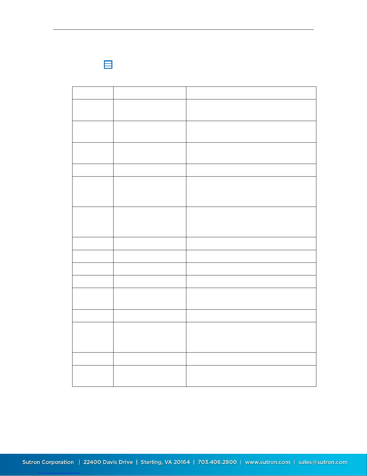
4.2.4. Main Menu While in Station View
Press the button in the upper left to access the main menu. When a station
view is active, the main menu offers the following options:
* - not present if working offline
Page 32
Sutron Corporation X-Link Operations & Maintenance Manual, Rev 1.63 5/24/2016 pg. 32
4.3. Dashboard Tab
The Dashboard tab is the first tab displayed after you connect to X-Link. When
LinkComm connects to X-Link, it always retrieves the current station status, and
current data values for measurements, and displays this data on the Dashboard.
The data displayed on the Dashboard always reflects the state of X-Link the last
time you refreshed status, regardless of the measurements you may or may
not have defined under Measurements.
To refresh the current status, click the Refresh Status button
To reset the station status, including the transmission counters, tallies and
system errors, click the Clear Status button. Once the status is reset, the
previous status is lost
To show the status text actually received from the logger, press the Show
Details button
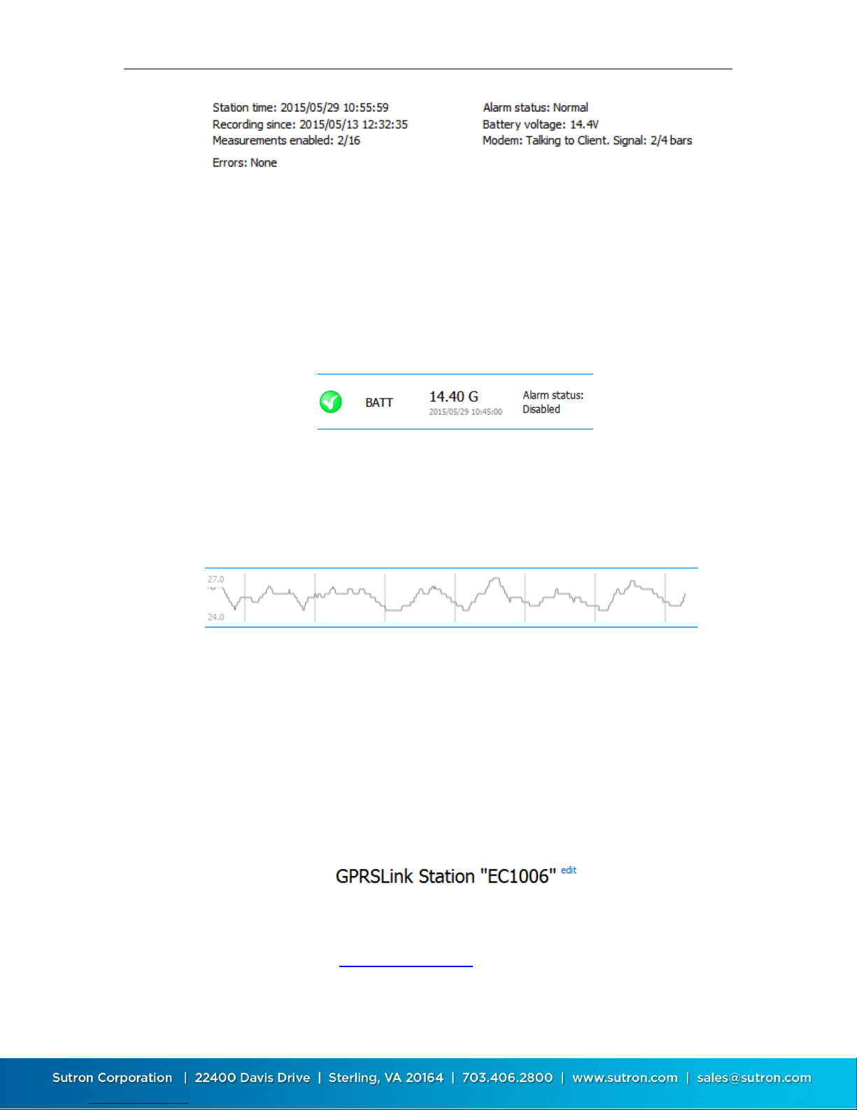
4.3.1. Station Status
The upper left of the Dashboard tab displays the most important information
about the station, including the station time, recording start time, number of
measurements enabled, etc.
Page 33
Sutron Corporation X-Link Operations & Maintenance Manual, Rev 1.63 5/24/2016 pg. 33
High level telemetry status is also shown on this page. To see low level details
about telemetry, please see the Telemetry tab. If the station has any active
errors, these are shown in RED just below the status area.
4.3.2. Current Data
Just below the station status area, LinkComm displays current data values, the
time the data values were measured, and the alarm status for each data item.
This data is updated every time you click Refresh Status.
4.3.3. Recent Data Graph
A graph of the recent data (over the last 7 days) is displayed next to current data,
for each item being measured by X-Link. This graph is automatically populated
with data on connect only if you have Get recent data on connect checked in the
station Connection Settings.
Right-clicking on the graph (or touching the graph in the mobile app), reveals a
pop-up menu that allows you to:
Refresh recent data (all items, not just the selected)
View the current data item in the larger graph on the Data tab
4.3.4. Changing the Station Name
The station name can only be changed from the Dashboard tab, and is actually
the only setup item that can be changed from the Dashboard tab. To change the
station name, press the blue “edit” text, next to the station name.
LinkComm will prompt for the new station name. Just as with every other station
setup change, the change is not complete until you have sent the setup to X-Link.
Do this using either the setup status button in the main header, or the Send
Setup to X-Link item in the main menu.
Page 34
Sutron Corporation X-Link Operations & Maintenance Manual, Rev 1.63 5/24/2016 pg. 34
4.4. Measurements Tab
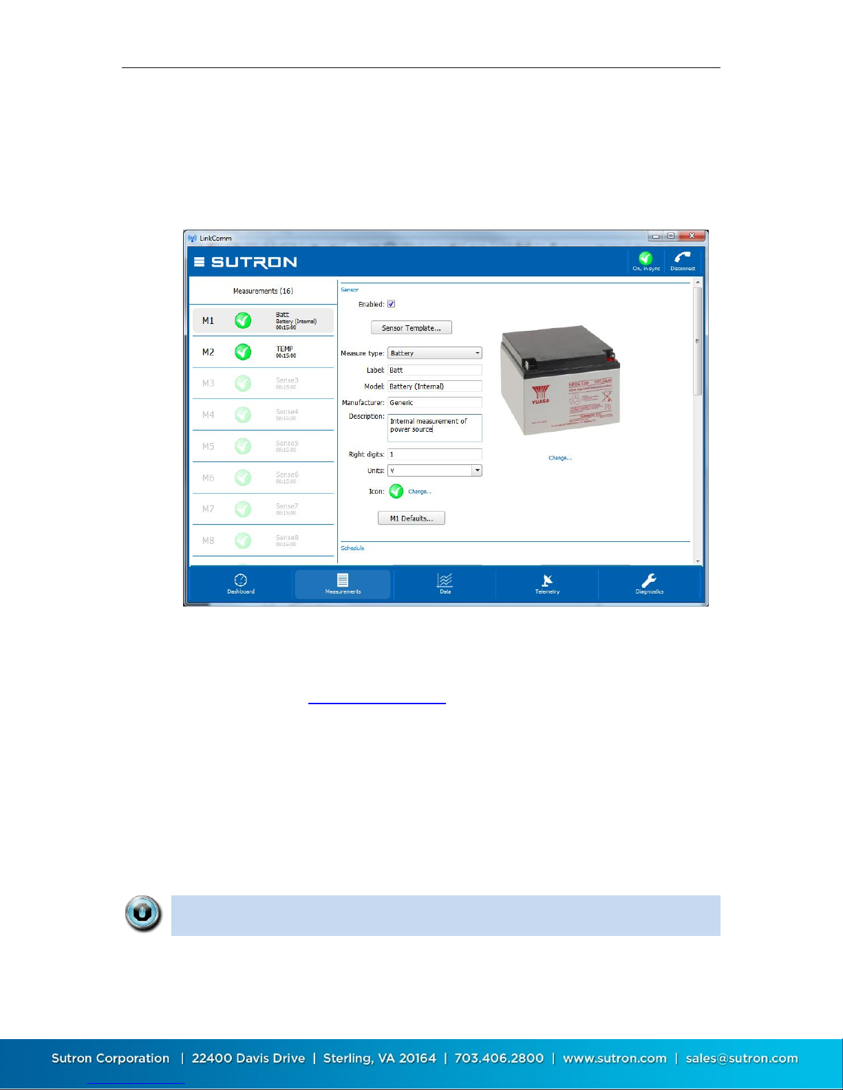
The measurements tab is the first tab displayed when you select Work Offline in
the stations list view. This is the tab where all sensors are configured. Up to 16
sensors may be enabled and configured. The measurements tab also provides
some test functions to help you ensure the sensor is properly configured.
The left side of the measurements tab shows a list of all possible measurements.
The right side of the measurements tab shows the details of the selected
measurement. Only the high level details of using the measurements tab is
discussed here. See Measurement Setup for details on configuring measurement
settings.
4.4.1. Using Sensor Templates
LinkComm provides templates for many sensors often used with X-Link. The
templates configure default settings for the most important sensor parameters,
and also includes sensor metadata, e.g., a picture of the sensor, its wiring
diagram, manufacturer, model, description, and units.
Note: Sensor metadata (picture, wiring diagram, etc.), is NOT stored in the XLink logger, but only in the station definition in LinkComm.
Page 35
Sutron Corporation X-Link Operations & Maintenance Manual, Rev 1.63 5/24/2016 pg. 35
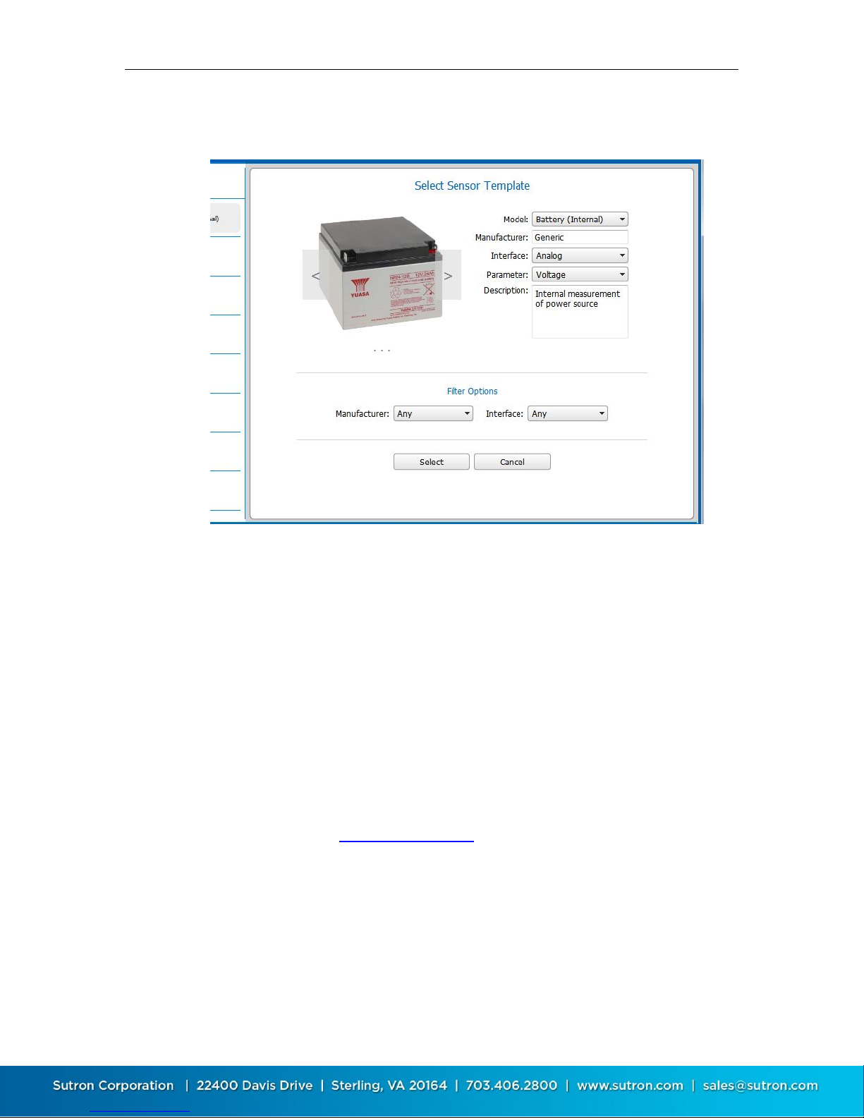
To set up a sensor using a sensor template, press the Sensor Template… button.
The following dialog is displayed.
You browse for different available templates by pressing the arrows displayed
over the sensor picture (which are only shown when the mouse hovers over
them), or by using the Model: drop-down control. On LinkComm for mobile
devices, you can swipe the sensor image with your finger to select different
templates.
Use Filter Options to show only a subset of sensor templates. For example, you
can show only those sensor templates for a particular Manufacturer, or only
those sensor templates for a particular sensor Interface (SDI-12, Analog, Digital,
etc.).
To use the selected template for configuring the measurement, press the Select
button. The settings from the template are then applied to the measurement
setup. As always, the changes must be sent to X-Link in order to take effect. Do
this either by using the setup status button, or by selecting the Send Setup to X-
Link item on the main menu.
To cancel and close the template dialog without using the template to configure
the current measurement, press the Cancel button. Note that selecting another
measurement in the measurement list on the left side of the Measurements tab
automatically cancels and closes the dialog.
Page 36
Sutron Corporation X-Link Operations & Maintenance Manual, Rev 1.63 5/24/2016 pg. 36
4.4.2. Resetting Measurement Defaults
A measurement entry can be reset to its default values by pressing the Mx
Defaults button, which appears at the bottom of the Sensor settings section of
the measurement settings, just above the schedule settings.
When you use the Mx Defaults button to reset measurements settings, any
metadata you’ve associated with the sensor (sensor picture, Model,
Manufacturer, Description, and Units) is also reset to defaults.
4.4.3. Verifying the Measured Value
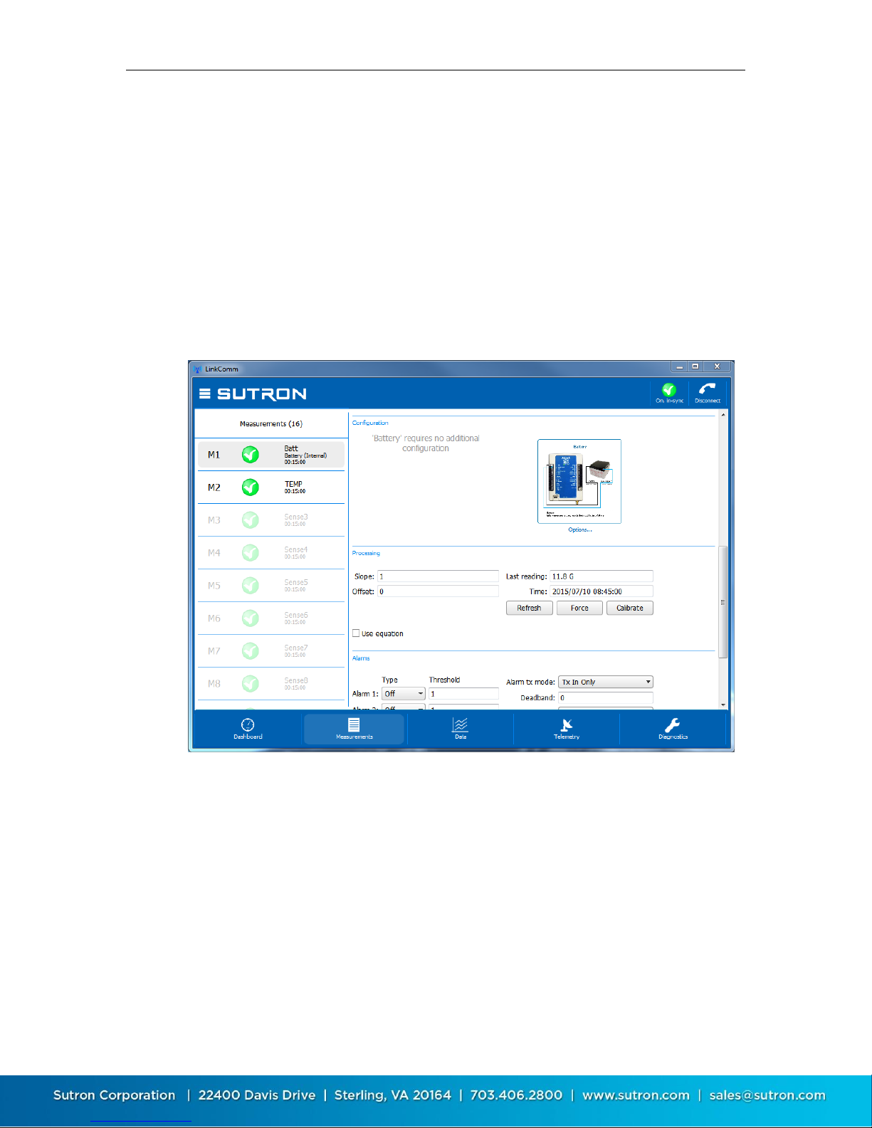
The Processing section of the measurement settings contains buttons to help
you verify the measured value is correct.
Press the Refresh button to retrieve and display the current value of the
measurement from X-Link. Press the Force button to cause X-Link to take a new
measurement. Press the Calibrate button to calibrate the sensor.
When you press the Calibrate button, LinkComm will prompt you to enter the
desired value for the measurement, showing you its current measured value as a
reference, and then compute a new Offset setting based on the value you enter.
Page 37
Sutron Corporation X-Link Operations & Maintenance Manual, Rev 1.63 5/24/2016 pg. 37
4.5. Data Tab
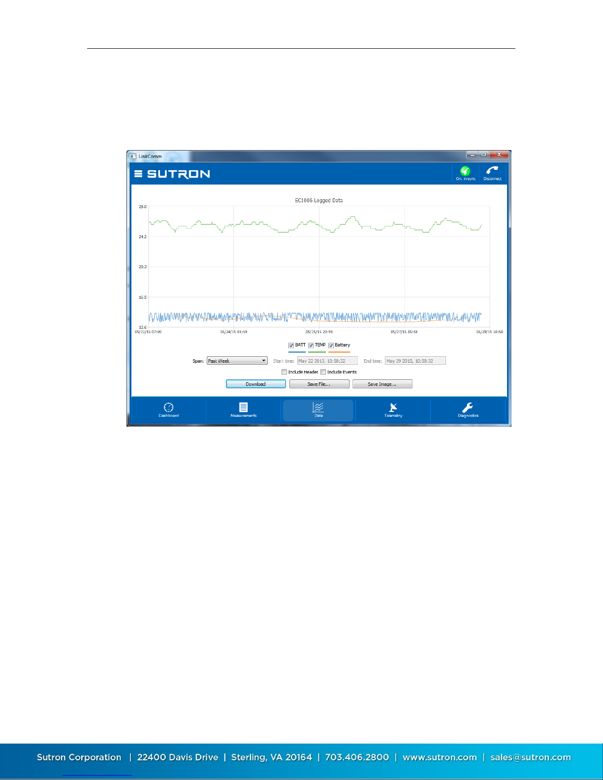
The data tab shows historical measurement readings made by X-Link. If recent
data was downloaded when connecting to X-Link, the graph displays this data
the first time you select the Data tab.
To zoom-in on subsets of data, click-and-drag to create a rectangle around the
data you want to zoom to. To restore the zoom to all data, double-click. When
using a touchscreen, you may use your finger to draw the rectangle, and doubletap to reset the zoom.
Right-clicking (or touching) the graph will show a menu allowing you to select all
series, deselect all series, or show points. You may select or deselect individual
data series for display using the legend just below the graph.
Change the span of the period to graph using the Span control. Several options
are available. Whenever a change to span is made, you must press the
Download button to retrieve the data for display. When the defined span no
longer matches the displayed span, the download button text changes to
“Download***”.
Press Save File… to save the raw data to a text file. Press Save Image… to save an
image of the graph to disk. On mobile platforms, rather than save files to disk,
you are prompted to “share” the files via other services like Email, Dropbox (if
installed), etc.
Page 38
Sutron Corporation X-Link Operations & Maintenance Manual, Rev 1.63 5/24/2016 pg. 38
4.6. Telemetry Tab
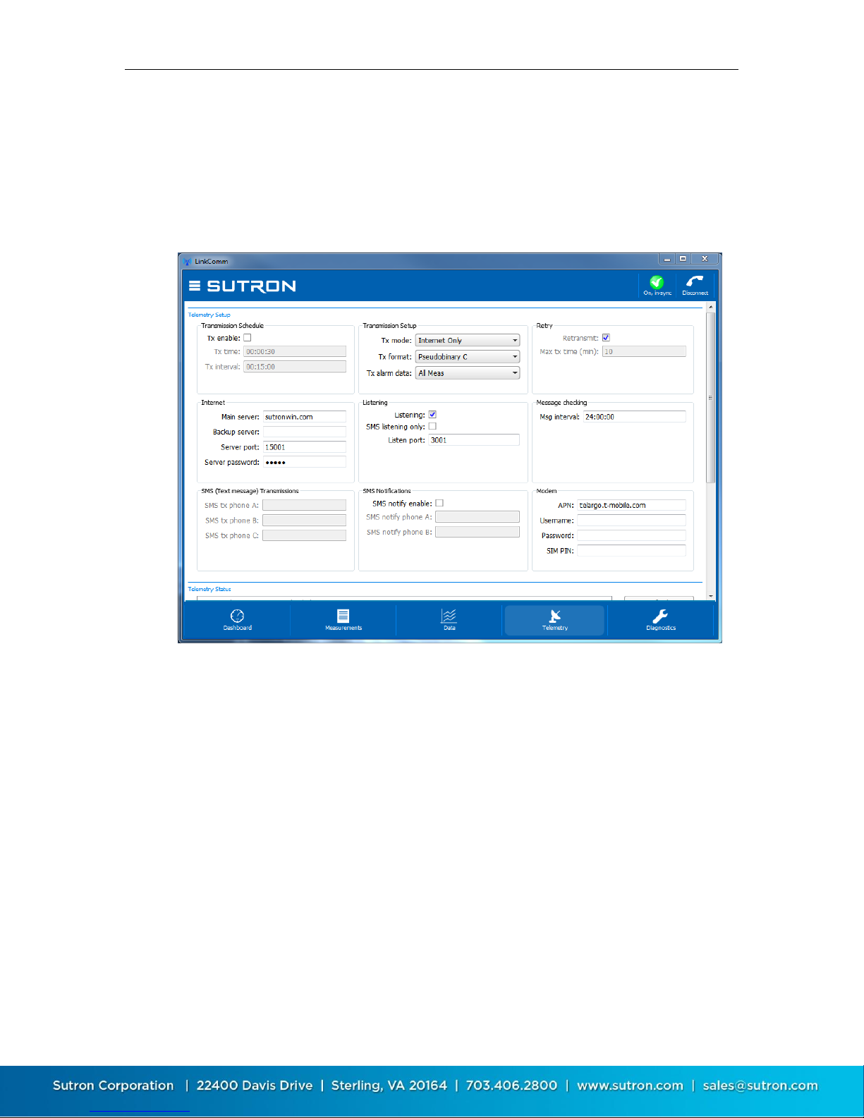
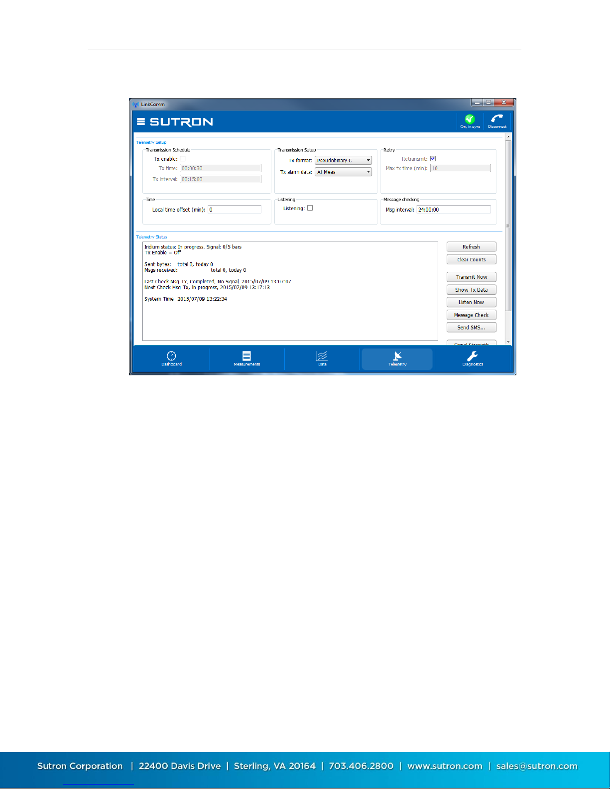
The Telemetry tab is used to configure a station for Iridium or Cellular
communications and data reporting. The contents of the tab differ for each
telemetry type.
Telemetry tab showing cellular settings:
The telemetry status section is below the setup area, and is accessed by scrolling
down.
Page 39
Sutron Corporation X-Link Operations & Maintenance Manual, Rev 1.63 5/24/2016 pg. 39
Telemetry tab showing Iridium settings:
4.6.1. Telemetry Status
Telemetry status is displayed on the telemetry tab, just below the telemetry
setup. You may need to scroll down to see the status section.
The status text is retrieved from X-Link the first time you display the telemetry
tab, and can be refreshed as needed on demand.
Press the Refresh button to update the status text to the latest
Press the Clear Counts button to clear all telemetry tallies
Press Transmit Now to cause X-Link to transmit now
Press Show Tx Data to show the data in X-Link’s transmit buffer
Press Listen Now to have X-Link start listening for incoming TCP/IP
connections
Press Message Check to have X-Link check for incoming messages over
Iridium SBD or Cellular SMS
Press the Signal Strength button to open a dialog showing a graph of the
signal strength over time
Page 40
Sutron Corporation X-Link Operations & Maintenance Manual, Rev 1.63 5/24/2016 pg. 40
4.7. Other Setup
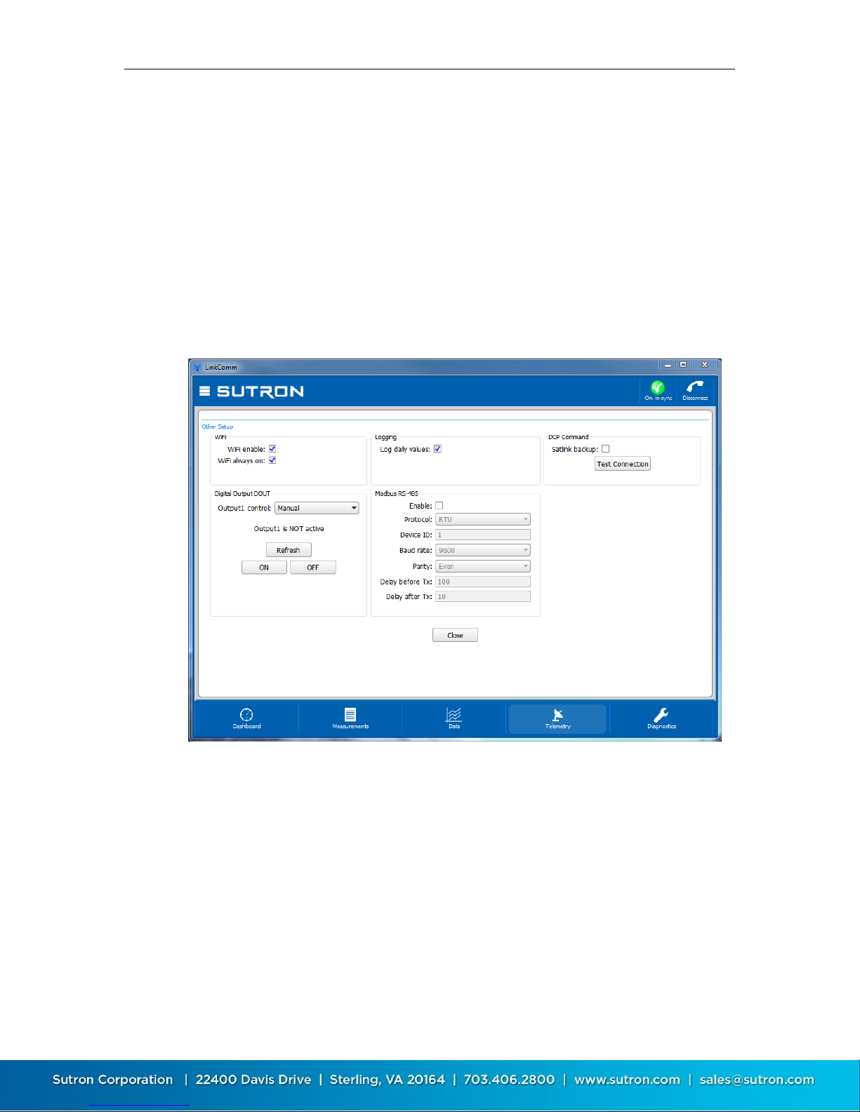
Various settings are displayed in the Other Setup dialog, which is accessed from
the Telemetry tab by pressing the Other Setup button. The settings shown
include those for:
Wi-Fi
Log daily values
DCP Command
Digital Output DOUT
Modbus RS-485
The controls in the Digital Output DOUT section can be used to view the status
of the digital output, and to control its state. Press the Refresh button to display
the current state of DOUT. The current state is displayed just above the button.
Press the ON button to turn DOUT on. Press the OFF button to turn DOUT off.
The Test Connection button is used to confirm communication between X-Link
and a Satlink, when X-Link is being used in a DCP Command configuration.
Close the Other Setup dialog by pressing the Close button.
Page 41
Sutron Corporation X-Link Operations & Maintenance Manual, Rev 1.63 5/24/2016 pg. 41
4.8. Diagnostics Tab
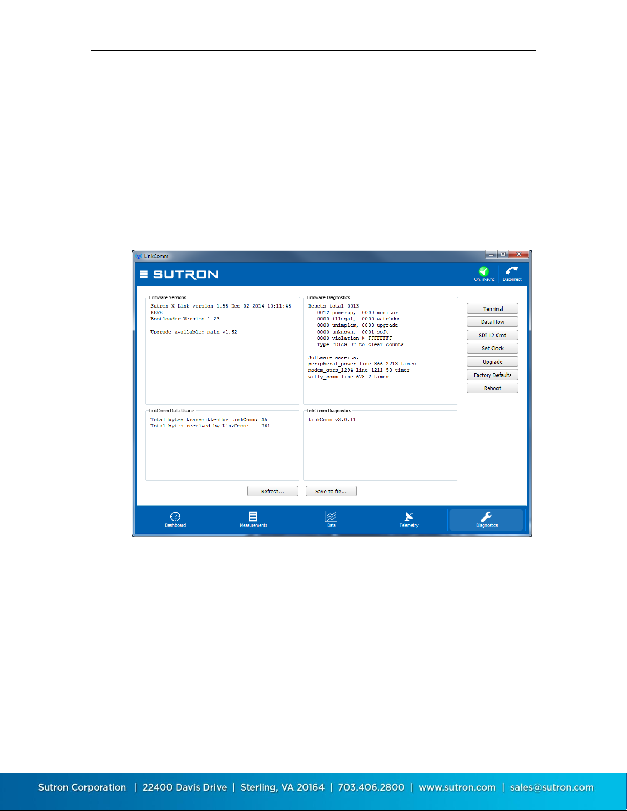
This tab provides extensive diagnostics information, and offers tools for
performing various diagnostics and maintenance operations. For example:
Get diagnostics information including software versions and data usage
Terminal and Data Flow views
SDI-12 command utility
Set the clock in X-Link
Upgrade X-Link
Resetting X-Link to factory defaults
4.8.1. Firmware Versions and Diagnostics
The top two text areas on the Diagnostics tab display information about the
firmware installed in the connected X-Link.
The Firmware Versions section displays the current versions of firmware
installed in X-Link. If LinkComm detects a newer version of firmware is available,
this text area contains a message saying such. The Firmware Diagnostics area
displays recent diagnostics information reported by X-Link.
Press the Refresh… button to update this data to the latest. Press the Save to
file… button to save all diagnostic text data to an external file.
Page 42
Sutron Corporation X-Link Operations & Maintenance Manual, Rev 1.63 5/24/2016 pg. 42
4.8.2. LinkComm Versions and Diagnostics
The bottom two text areas on the Diagnostics tab display information about
LinkComm.
The LinkComm Data Usage section displays the total byte counts between
LinkComm and X-Link for the current session. The LinkComm Diagnostics section
displays LinkComm’s version information.
Press the Refresh… button to update this data to the latest. Press the Save to
file… button to save all diagnostic text data to an external file.
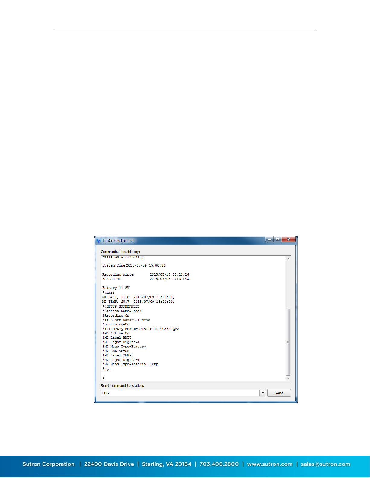
4.8.3. Terminal
LinkComm features a built in terminal monitor program. All communications
between LinkComm and X-Link uses the command line interface. The Terminal
window can be used to view a history of command traffic, and can be used to
access the command line interface directly.
To see the details of the communication between LinkComm and X-Link, bring up
the terminal window via the Terminal button on the Diagnostic tab.
You may type into the terminal window. Data typed will be sent to X-Link. Any
replies from X-Link will be shown in the Terminal window.
Page 43
Sutron Corporation X-Link Operations & Maintenance Manual, Rev 1.63 5/24/2016 pg. 43
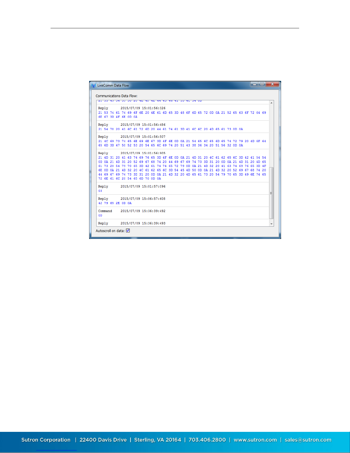
4.8.4. Data Flow
The Data Flow dialog shows recent command line traffic expressed in terms of
binary byte values, and shows traffic direction and timestamp information. To
open the dialog, press the Data Flow button on the Diagnostic tab.
When “Autoscroll on data” is checked, the window advances when new data
becomes available.
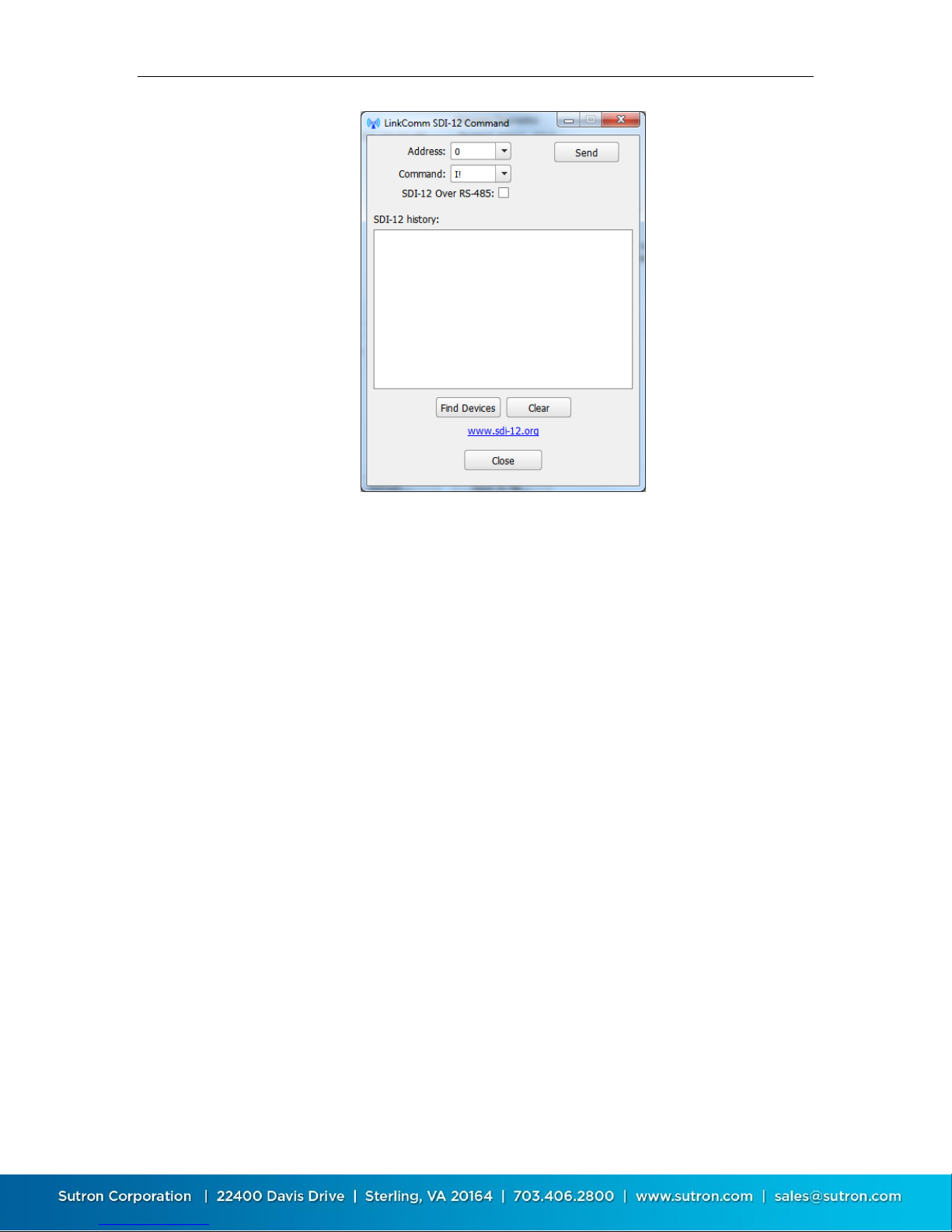
4.8.5. SDI-12 Command Utility
The SDI-12 command utility dialog is used to send SDI-12 commands to sensors
connected to X-Link. It can also be used to quickly find what sensors are
connected to the SDI-12 bus.
Page 44
Sutron Corporation X-Link Operations & Maintenance Manual, Rev 1.63 5/24/2016 pg. 44
To send a command to an SDI-12 device connected to X-Link, enter the Address
and Command fields, and then press the Send button. Be sure to check SDI-12
over RS-485, if you need to send the command over the RS-485 bus. The results
of the command are shown in the SDI-12 history window.
To have X-Link look for any and all sensors on the SDI-12 bus, press the Find
Devices button. Information regarding what sensors are found is displayed in the
SDI-12 history window.
Press the Clear button to clear the SDI-12 history window.
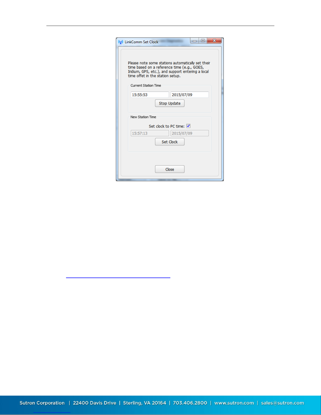
4.8.6. Setting the Clock
Press the Set Clock button on the Diagnostics tab to open the Set Clock dialog.
The Set Clock dialog is shown below:
Page 45
Sutron Corporation X-Link Operations & Maintenance Manual, Rev 1.63 5/24/2016 pg. 45
The top Start/Stop Update button is used to either start or stop polling X-
Link for its current time. The current time is displayed above the button
Check the Set Clock to PC time have the time set to match that of the PC,
once Set Clock is pressed
To set the time to a specific value, uncheck Set Clock to PC, enter the desired
time and date, and press the Set Clock button
4.8.7. Firmware Upgrade
The software running in X-Link can be upgraded. The latest version of X-Link
firmware is delivered as part of the LinkComm download package obtained from
the Sutron web site. LinkComm may be downloaded from
http://www.sutron.com/downloads.htm (search on “LinkComm”).
Upgrades may only be done via a direct USB cable.
Upgrade files are packaged into the same download with the LinkComm
program. Upgrade files will have names such as v1_05mainXLINK1298.upg and
v1_01bootOMEGA1298.upg.
To initiate an upgrade of your X-Link, select the Upgrade button on the
Diagnostics tab. If LinkComm detects a newer version of firmware on your PC,
LinkComm will suggest that an upgrade be made using it. If you select “No”, then
use the file-open dialog that follows to browse for, and select, the upgrade file to
use.
Page 46
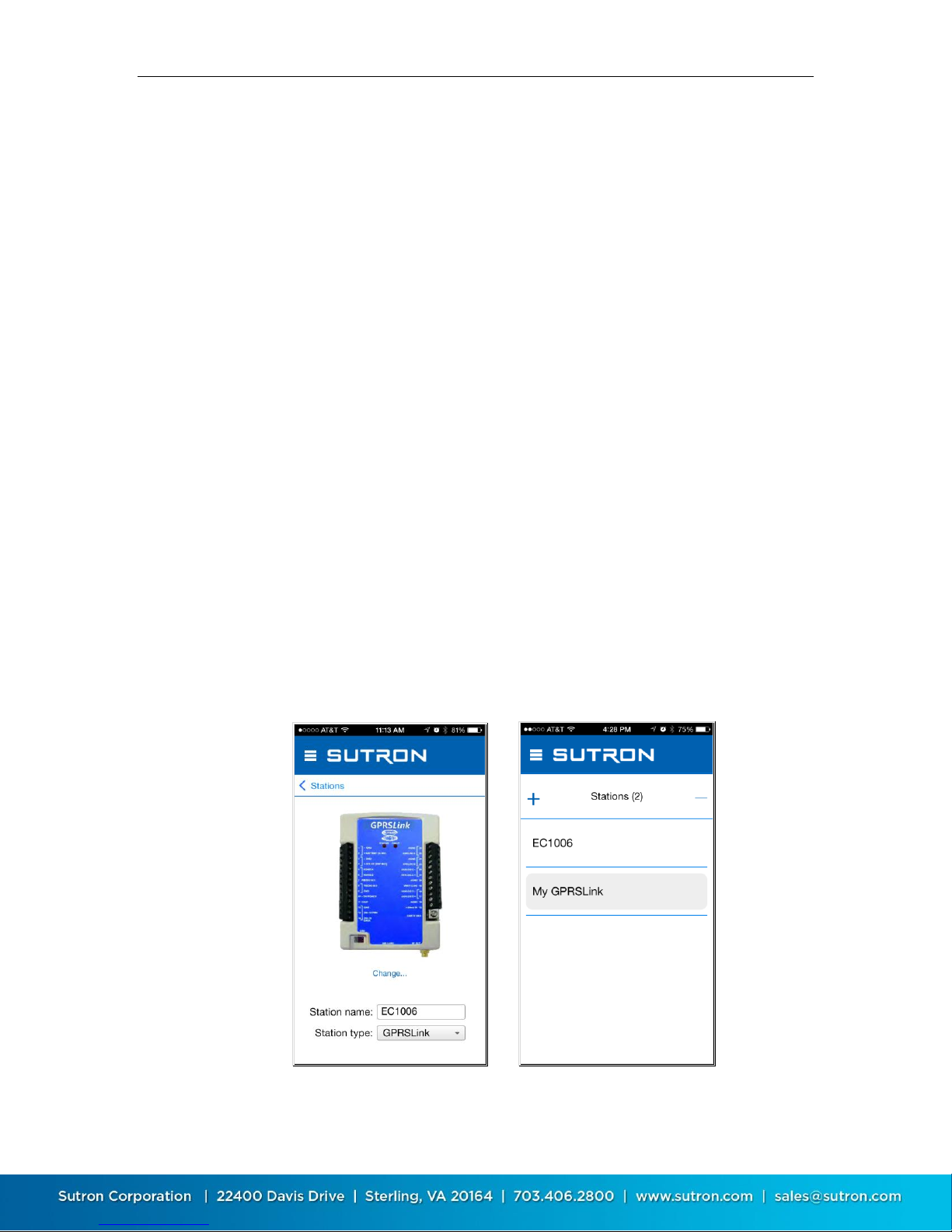
Sutron Corporation X-Link Operations & Maintenance Manual, Rev 1.63 5/24/2016 pg. 46
4.8.8. Setting to Factory Defaults
Setting the station to factory defaults will permanently erase all setup and
status. The setup will be set to defaults. To set X-Link to factory defaults, press
the Factory Defaults button on the Diagnostics tab and answer “Yes” to the
prompt for confirmation.
4.8.9. Rebooting X-Link
Clicking the Reboot button on the Diagnostics tab will have LinkComm issue the
reboot command to X-Link. X-Link will perform a software reset. LinkComm will
then disconnect from X-Link.
If you are issuing the command remotely, please note that X-Link will need a
minute to get back on the internet before it is ready to talk again.
4.9. LinkComm for Phones and Tablets
LinkComm is available not only for PC and Mac, but also for iOS and Android
phones and tablets. On smaller screens, LinkComm is not able to show as much
information at one time.
4.9.1. Stations List
On phones and tablets, the station list is normally hidden, and must be accessed
by selecting a link.
To access the stations list in the stations list view, press the Stations link just
below the main menu icon.
Page 47
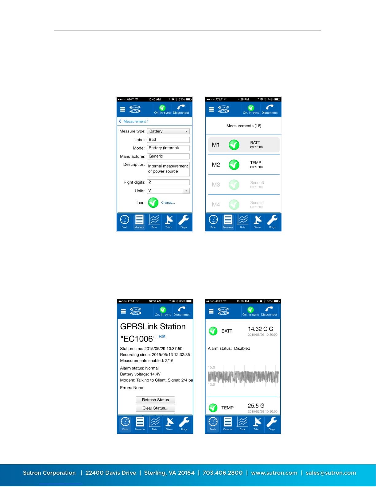
Sutron Corporation X-Link Operations & Maintenance Manual, Rev 1.63 5/24/2016 pg. 47
4.9.2. Measurements List
On phones and tablets, the measurements list is normally hidden, and must be
accessed by selecting a link. To access the measurements list on the
Measurements tab, press the Measurement X link just below the main menu
icon.
4.9.3. Scroll Down to See What Used to be Right
On phones and tablets, you may need to scroll down to see data normally
displayed to the right when using the desktop version of LinkComm.
For example, the following images show how the Dashboard tab arranges
content vertically:
Page 48

Sutron Corporation X-Link Operations & Maintenance Manual, Rev 1.63 5/24/2016 pg. 48
5. Telemetry
Every X-Link features a built in communication device that is used to deliver data
collected from sensors.
GPRSLink, HSPALink, and CDMALink use the cell phone network to send the
data.
IRIDIUMLink uses Iridium satellites for the data transmission.
X-Link can be set up to make scheduled transmissions, delivering sensor data on
a regular interval. This is a common method of receiving your environmental
data.
We use the shorthand name Tx to mean transmission. ReTx means
retransmission.
Every X-Link station can be remotely accessed while it is in the field in order to
change the setup, check the status, access the log, and perform nearly any other
operation.
A GPRSLink, HSPALink, or CDMALink may be remotely accessed using
LinkComm.
An IRIDIUMLink unit cannot establish a remote connection to LinkComm.
However, messages may be sent to any IRIDIUMLink via email, and
IRIDIUMLink can reply to them. It is possible to accomplish most any
operation via those messages including setup change, status check, and log
access.
X-Link can be set up for alarms. When a sensor reading reaches a user set
threshold, X-Link can send transmissions and messages informing the customer
about the alarm condition. This is useful for applications where it is important to
know about environmental conditions as soon as they happen.
Additionally, GPRSLink, HSPALink, and CDMALink units can be set up to receive
incoming connections via the Listening feature. In this case, a program like the
Sutron AutoPoll can be used to periodically gather data from X-Link. When
scheduled transmissions are set up, X-Link initiates the data transfer; in Listening
mode, an application starts the communication with X-Link.
X-Link performs message checking at least once every 24 hours. Version 1.46 is
required for message checking. A message check is the process of using X-Link's
modem to see if there are any messages waiting.
Several types of transmissions are sent by X-Link:
Page 49

Sutron Corporation X-Link Operations & Maintenance Manual, Rev 1.63 5/24/2016 pg. 49
Scheduled: these transmissions occur periodically, a time designated by the
user settings Tx Time and Tx Interval.
Alarm: alarm transmissions happen when a sensor reading goes into alarm
range.
Forced: Forced transmissions may be initiated by the user. They are used to
test a station during an installation. Additionally, a message may be sent to a
station requesting a forced transmission with specific data. SMS notification
messages are considered forced transmissions too.
5.1.1. Scheduled Transmission Process
The basic transmission process consists of the following steps:
1. Measurement data is read from the log and formatted into the transmission
buffer.
2. The modem is powered on and communication to the modem is tested.
3. Data is taken from the transmission buffer and handed to the modem. If the
station is sending a message, some data may remain in the transmission
buffer.
4. The modem is asked to send all the data to its destination.
5. IRIDIUMLink sends a message to the satellite.
6. GPRSLink, HSPALink, and CDMALink setup to transmit data to a server opens
a TCP/IP connection.
7. GPRSLink, HSPALink, and CDMALink setup for SMS messages sends a
message.
8. If a connection is not established, X-Link will retry for Max Tx Time, which is
10 minutes by default.
9. IRIDIUMLink checks for incoming messages and handles them immediately. If
a message requested a response, the response data is handed to the modem.
10. If there is any data left in the transmission buffer, go back to step 3.
11. GPRSLink, HSPALink, and CDMALink checks for incoming messages and
handles them immediately. If a message requested a response, the response
data is handed to the modem.
12. Power to the modem is turned off.
Page 50
Sutron Corporation X-Link Operations & Maintenance Manual, Rev 1.63 5/24/2016 pg. 50
5.2. Retransmissions
Starting with version 1.57, X-Link is able to make retransmissions (ReTx).
Retransmissions are retries of failed scheduled transmissions.
When a scheduled transmission fails, X-Link notes the time of the failure. Once a
future scheduled transmission succeeds, X-Link will proceed to re-transmit the
data from the missing transmissions.
Here is an example of retransmissions in action:
o 12:00 Scheduled transmission succeeds. All is well.
o 12:30 Scheduled transmission fails due to lack of network.
o 13:00 Another scheduled transmission fails.
o 13:30 Scheduled transmission succeeds. Network is back up.
o 13:31 Retransmission with data as if it were 12:30 completes.
o 13:32 Retransmission with data as if it were 13:00 completes. All
previously missing data has been transmitted.
o 14: 00 Scheduled transmission completes. Back to business as usual.
For retransmissions to take place, the setting Retransmit must be enabled. It is
enabled by default. A proper Tx Format is also needed to ensure that the data in
the transmission is timestamped. Pseudobinary B is the only unacceptable
format. Use Pseudobinary D instead of Pseudobinary B.
Enable Retransmit and choose any Tx Format but Pseudobinary B to take
advantage of Retransmissions.
o Toggling recording, clearing status, and changing telemetry settings will
reset retransmissions. Rebooting a station will NOT reset transmissions.
o If X-Link does not have any data logged for the relevant time period, no
retransmission will be made.
o Loss of power cannot be overcome with retransmissions.
o Retransmissions are only useful if X-Link is still able to collect and log
sensor data.
o Data older than 7 days will not be retransmitted.
o If there are pending retransmissions, Telemetry status will show when
the first failure happened. E.g. "Retransmissions pending from
2014/11/19 12:30:00"
Page 51
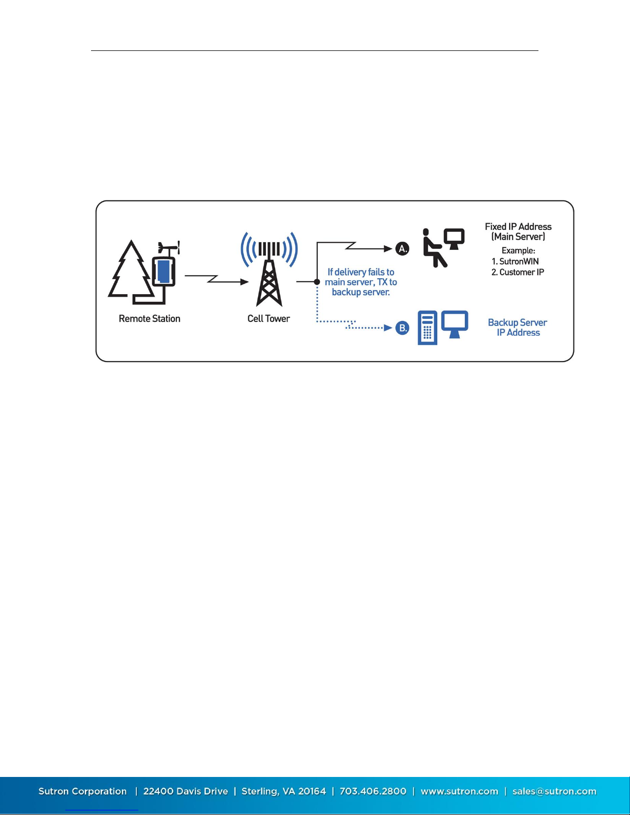
Sutron Corporation X-Link Operations & Maintenance Manual, Rev 1.63 5/24/2016 pg. 51
5.3. Cell Phone Telemetry
GPRSLink, HSPALink, and CDMALink use the cell phone network to connect to
the internet and deliver sensor data.
The internet connection enables X-Link to get in touch with a server that will
accept the sensor data. The diagram below shows the typical usage scenario
where the station communicates to a fixed IP or IP with a backup server:
5.3.1. Antenna Placement
GPRSLink, HSPALink, and CDMALink must be installed in places with usable cell
phone coverage. The antenna aiming feature can help determine the quality of
signal at installation time.
5.3.2. Two-Way Communication
Whether making a transmission to a server or receiving a connection from a
client, GPRSLink, HSPALink, and CDMALink will have established a two-way
connection. Data will be transferred to and from X-Link in real time. This means
that you can use LinkComm to connect to X-Link and download the log, change
the setup, check the status, and do almost any other operation that can be done
over USB.
5.3.3. Scheduled Transmissions
Scheduled transmissions (sometimes called self-timed transmissions) are the
most common way of reporting data. X-Link is set up with a time and interval
dictating how often to deliver data. At designated times, X-Link will power up the
modem, establish a connection to the internet, get in touch with the user setup
primary server, and deliver the data. To use scheduled transmissions, X-Link
needs to be set up with the internet address of a primary server and, optionally,
a backup server so that it knows where to deliver the data. The backup server is
contacted only if the primary server cannot be reached.
Page 52

Sutron Corporation X-Link Operations & Maintenance Manual, Rev 1.63 5/24/2016 pg. 52
5.3.4. Listening
An X-Link can be set up to always be listening, which means that it will act as a
server, accepting TCP/IP incoming connections. Sutron's AutoPoll PC software
can periodically reach out to a listening X-Link station and collect sensor data
from X-Link. In the listening mode, X-Link will keep the modem on at all times,
resulting in higher power consumption.
The transmission status (use LinkComm's Telemetry tab or issue STATUS TX
command) indicates the IP address assigned to X-Link by the service provider.
The Listen Port setting determines which port X-Link remains open.
You can send X-Link a message with the TXLISTEN command that would cause it
to temporarily go into listening mode.
Listening is automatically turned on by X-Link for 10 minutes :
At boot up
When the station is connected to, whether via USB, over the modem, or
over Wi-Fi
When an SMS is received
When the wakeup button is pressed, and when the station goes into alarms,
listening is automatically turned on for one hour.
5.3.5. SMS Transmissions
X-Link can use SMS (text messages) to deliver sensor data. It can use SMS
messages as a primary means of data reporting, or only if the primary and
backup servers cannot be reached.
The system is able to make scheduled transmissions to IP servers and may be
configured to transmit SMS messages if communications fail to the IP addresses.
Additionally multiple phone numbers may be used:
Page 53
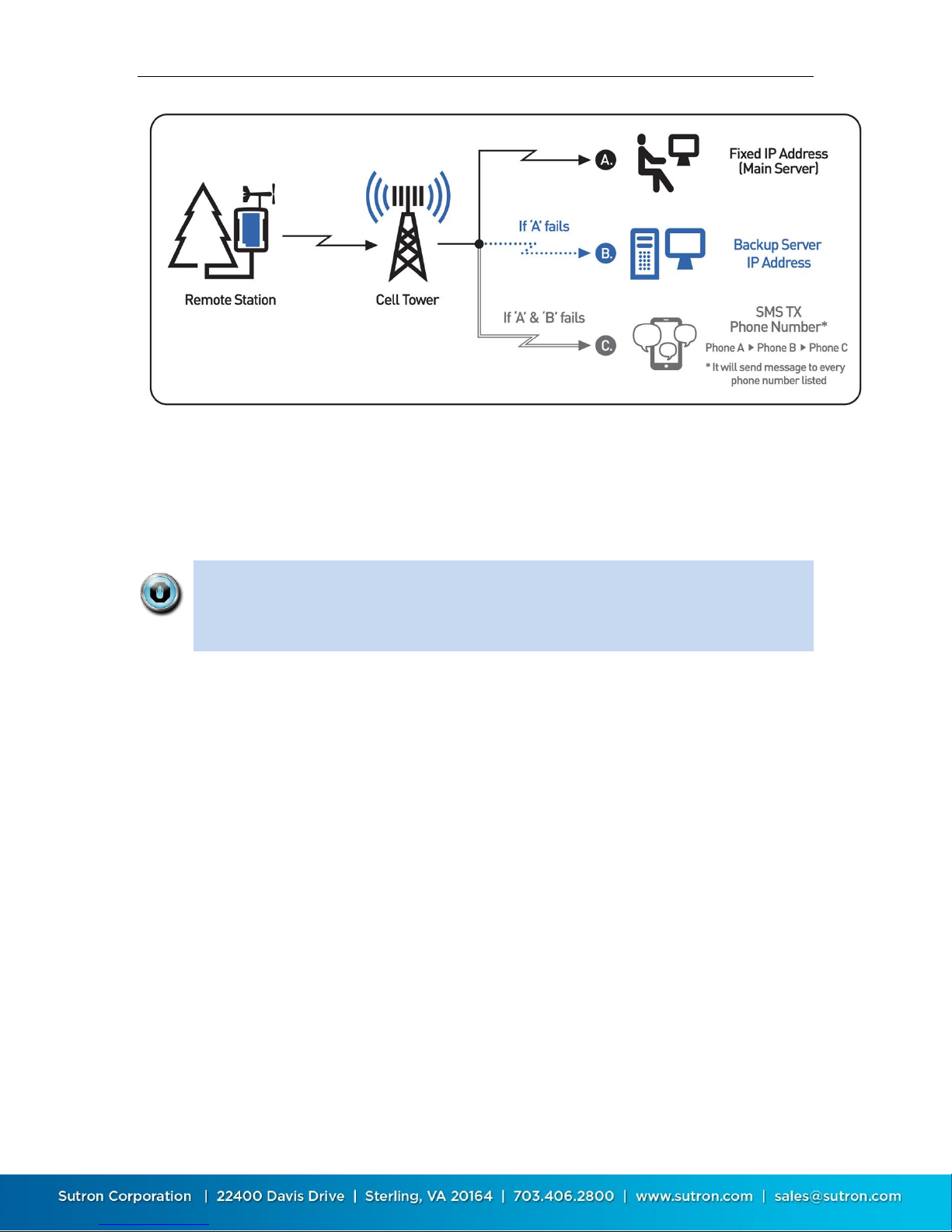
Sutron Corporation X-Link Operations & Maintenance Manual, Rev 1.63 5/24/2016 pg. 53
5.3.6. SMS Notifications
If SMS Notification is enabled by the customer, X-Link reports certain events via
SMS to a list of user-entered phone numbers (SMS Notify Phone). The purpose of
this feature is to notify the customer that a major event has transpired at the
station.
SMS notifications are meant to be sent to a customer's cell phone. They are
meant to be immediately read by a person (rather than a computer, like Sutron
WIN). SMS notifications are the way for a customer to receive notice a station
in alarm on his cell phone.
The following events cause notifications:
Alarms: Details such as which measurement went into alarm and the
measurement reading
Station Rebooted: The time the station rebooted is sent along with the kind
of reboot (power on, watchdog reset, upgrade, etc).
Recording on: When recording is started, a SMS message will be sent. Then
the recording is turned off, no SMS is sent.
Tx Bad: A scheduled transmission failed.
SDI-12 sensor failure: An SDI-12 reading has failed. This notification is sent
only the first time the sensor fails and only once a day. The value logged is
the index of the measurement that failed.
All notifications have the same format. As only one SMS is sent per notification,
not all the data may fit. Here are some examples:
1. The station name is on the first line of the message.
Page 54

Sutron Corporation X-Link Operations & Maintenance Manual, Rev 1.63 5/24/2016 pg. 54
2. The next line contains the event that caused the notification. It will look like
the corresponding log entry except that there will be no timestamp.
3. The next line contains the measurement data for each active measurement
that has a valid last reading. It will include the name of the sensor, the most
recent reading, and any alarm details.
4. At the end of the SMS are the number of transmissions made today.
Below is the boot up notification. There is no measurement data because the
system had no time to make a reading.
DEV1GPRS
Reset Upgrade,1
Tx today: good 0, bad 0
Here is an alarm notification.
DEV1GPRS
Alarm In,4
BV 14 Into Alarm
STAGE 10.157
PRECIP 0.00
TEMP 25.7
Tx today: good 1, bad 0
The number 4 after Alarm In means that measurement 4 was in alarm. The
reading that caused the alarm is BV 14 Into Alarm. Into Alarm means the reading
caused the station to go into alarm. See the Alarms section for details. (page 90.)
Page 55
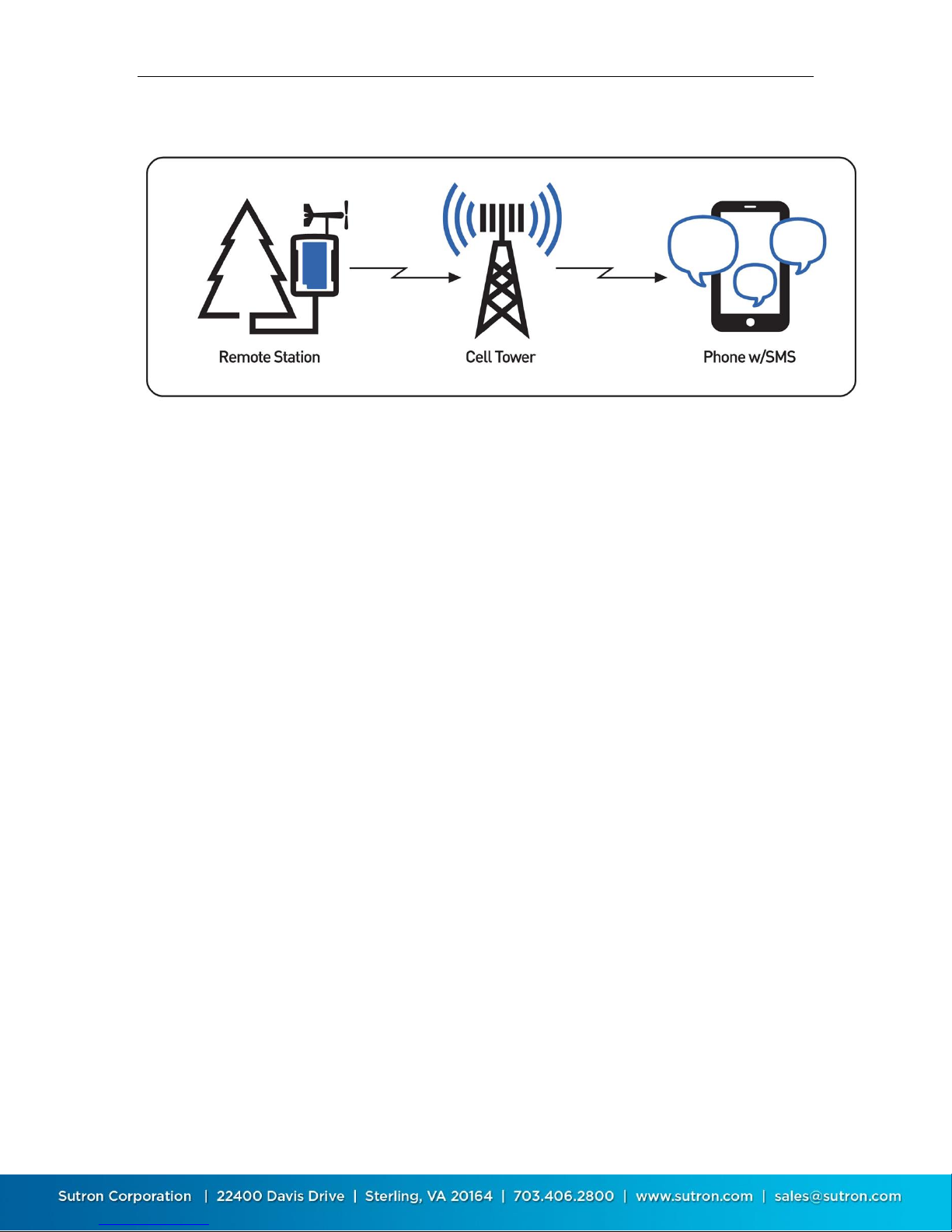
Sutron Corporation X-Link Operations & Maintenance Manual, Rev 1.63 5/24/2016 pg. 55
Below is a configuration where the station simply transmits SMS messages only:
5.3.7. SMS transmissions vs. SMS Notifications
When scheduled and alarm transmissions are set up to transmit via SMS (Tx
Mode = SMS and Tx Mode = Internet Fallback SMS), the transmissions are
expected to be received by a computer, such as Sutron WIN. It is not expected
that the customer will receive those on a cell phone. These transmissions are
formatted in whatever Tx Format the user selected, including Pseudobinary.
They are not meant to be read by a person. Instead, those transmissions are to
be collected by a computer and the sensor data placed into a database.
SMS notifications, on the other hand, are meant to be sent directly to a
customer's cell phone. Those notifications are formatted so that a person can
read and understand them.
Here is an example of the difference:
SMS transmission:
C2+AAyMf@[email protected]
SMS notification:
SUTRON DEV 1
Alarm In, 4
BV 13.8720 In Alarm
STAGE 10.157
PRECIP 0.00
TEMP 24.2
Tx today: good 1, bad 0
5.3.8. FCC Approval for Internal Cellular Modems
This device complies with Part 15 of the FCC Rules. Operation is subject to the following
two conditions:
(1) this device may not cause harmful interference, and
(2) this device must accept any interference received, including interference that
may cause undesired operation.
Page 56
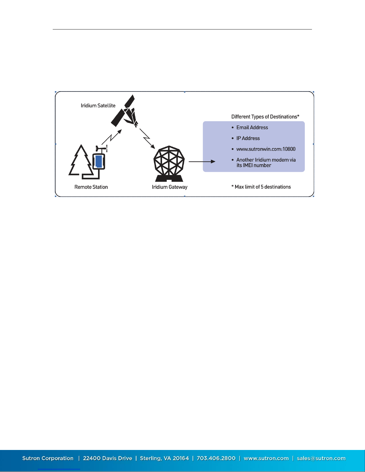
Sutron Corporation X-Link Operations & Maintenance Manual, Rev 1.63 5/24/2016 pg. 56
5.4. Iridium Telemetry
IRIDIUMLink uses the Iridium satellite constellation to deliver sensor data.
Iridium satellite coverage is available everywhere. The diagram below shows
how the signal travels through the Iridium Gateway to an email address, etc.
5.4.1. Iridium Antenna Placement
IRIDIUM Link's antenna must be placed where it has a clear view of the sky.
Iridium satellites are not geostationary. This means that coverage of a certain
area may vary from one minute to the next. The station must have a strong
signal for 10 to 20 minutes.
The antenna-aiming feature can aid in correct station setup. It will show the
current signal strength. Signal strength ranges from 0 (no signal) to 5 (excellent
signal).
A signal strength of 4 or higher indicates a strong signal.
IRIDIUMLink needs to consistently report a strong signal for 10 to 20 minutes
to indicate good antenna placement.
If signal strength is varying, the antenna's view of the sky is obstructed.
In theory, any signal strength above 0 means that a transmission can be
made. However, to ensure reliable and consistent data transmissions,
reposition the antenna to get better signal.
A signal strength of 0 indicates that there is no signal at all; IRIDIUMLink will
not be able to make any transmissions.
Page 57

Sutron Corporation X-Link Operations & Maintenance Manual, Rev 1.63 5/24/2016 pg. 57
When installing the station, make sure IRIDIUM link consistently reports a
signal strength of 4 or higher for at least 10 minutes.
5.4.2. Short Burst Data
X-Link uses the Iridium Short Burst Data (SBD) capability to send transmissions
and receive messages.
Unlike GPRSLink, HSPALink, and CDMALink which set up a two-way
communication, IRIDIUMLink uses messages to communicate. Messages may be
sent to IRIDIUMLink, and IRIDIUMLink may send messages in return.
5.4.3. Iridium Message Checking
When a scheduled transmission is made, IRIDIUMLink is notified of any incoming
messages. Checking for messages in this fashion does not incur any additional
data usage costs.
If your station is set up to make transmissions every 30 minutes, that means that
it will take up to 30 minutes for IRIDIUMLink to receive any messages sent to it. If
that is too long, you may consider turning on Listening (see below.)
5.4.4. Listening
If Listening is enabled, IRIDIUMLink keeps the modem powered on all the time.
This enables the immediate reception of any messages sent to IRIDIUMLink.
However, it also increases power usage.
To reduce power consumption but still check for messages, please see the
Message Check section on page 61.
5.5. Sending Messages to X-Link
GPRSLink, HSPALink, and CDMALink can receive SMS (text messages).
IRIDIUMLink can have messages sent via emails that get routed through the
Iridium system.
If Listening is enabled, X-Link receives messages immediately. In this mode, the
modem is always on, and the station consumes more power.
If Listening is disabled, X-Link checks for messages when it makes a transmission.
If the station is set up with a Tx Interval of 15 minutes, it may take up to 15
minutes for the station to receive the message sent to it. With Listening disabled,
X-Link turns off the modem between transmissions to save power.
Additionally X-Link can be setup to do periodic message checking. No matter
how it is setup, X-Link will do a message check every 24 hours as long as it has
power. Please see the Message Check section on page 61.
Page 58
Sutron Corporation X-Link Operations & Maintenance Manual, Rev 1.63 5/24/2016 pg. 58
When X-Link is turned on, it keeps the modem on for ten minutes. During that
time, it will receive messages immediately. When it does receive a message, XLink will keep the modem turned on for ten additional minutes to facilitate
additional message conversations.
Messages are treated like command line input with a few differences. Some
commands cannot be executed via a message (e.g. log download). Other
commands may have a differently formatted output (in order to reduce message
size).
See the Sending Messages section in the Command Line Interface chapter for
details on what the content of the messages should look like. (page 129.) Do
not forget to precede the commands with an exclamation point if you want the
station to reply.
To check the status of your station, send it the message
!STATUS
Password protected stations will need login information to be the very first thing
in a message:
LOGIN=XXX; !STATUS
X-Link remembers the last message received since boot up. To see it, press the
Refresh button on LinkComm's Telemetry tab or issue the STATUS TX command.
5.5.1. Sending SMS to X-Link
You can send a message to an X-Link using your cell phone. To find out the
phone number of your X-Link, have it send you a message first. To do so, use the
Send SMS button in LinkComm's Telemetry tab. X-Link does not know its own
telephone number.
X-Link will never send more than 4 SMS in reply to a command. As each SMS is
limited to 160 bytes, this means 640 bytes is the limit of any reply.
5.5.2. How X-Link Deletes Incoming SMS
X-Link does not keep old SMS. After it reads each incoming SMS, it will delete it.
This ensures that the SIM card of GPRSLink does not fill up preventing future
messages from being received.
5.5.3. Sending Messages to IRIDIUMLink
Email is used to send messages to IRIDIUMLink
The email message must be sent to [email protected]
Page 59

Sutron Corporation X-Link Operations & Maintenance Manual, Rev 1.63 5/24/2016 pg. 59
The email's subject must be the IMEI of the Iridium modem. Each
IRIDIUMLink will have its IMEI written on the front panel. Each transmission
made by IRIDIUMLink will be stamped with its unique IMEI.
The email needs an attachment containing the command(s) to be sent. The
attachment is a simple text file and it must have the .sbd extension. Example
file names: Status.sbd, MultiCmd.sbd
The body of the email should be blank. Do not put commands for
IRIDIUMLink into the body of the email.
The attachment may not be larger than 270 bytes.
Each command may be replied with no more than two messages, for a total
of 680 bytes.
The first byte of this file must be an ! in order for IRIDIUMLink to send a
reply. E.g. !STATUS
Multiple commands may be sent in a single message. Commands can be
separated with a new line or a semicolon ; E.g. !LAST; !STATUS;
5.6. Telemetry Status
X-Link keeps a variety of diagnostic information relating to remote
communications.
Some of the status is available via LinkComm's Main tab or by issuing STATUS on
the command line. Detailed status can be seen via LinkComm's Telemetry tab or
by issuing STATUS TX on command line.
5.6.1.1. General Status
Modem in use (GPRS, Iridium, etc.)
Current modem status
Last signal strength
Important telemetry setup such as Tx Enable and Listening
Number of good, bad, and retried transmissions made today
Number of incoming client connects total and today (clients such as AutoPoll
– GPRSLink, HSPALink, and CDMALink only)
Time and details of the next/current transmission
o Details include whether it is a forced, alarm, or scheduled transmission.
o Details also include the status of the transmission (scheduled, in
progress)
Time and details of last transmission(s)
o Details include whether it is a forced, alarm, or scheduled transmission.
o Details also include the status of the transmission (success, failed, reason
of failure)
Page 60

Sutron Corporation X-Link Operations & Maintenance Manual, Rev 1.63 5/24/2016 pg. 60
5.6.1.2. Diagnostic Status
IP Address (GPRSLink, HSPALink, and CDMALink only)
Number of good, bad, and retried transmissions made lifetime
Number of bytes transmitted today
Number of bytes received today (GPRSLink and HSPALink only)
Number of bytes transmitted lifetime
Number of bytes received lifetime (GPRSLink and HSPALink only)
Number of messages received lifetime
Last message received
o Iridium MT (include MTMSN) and Cell SMS only
Last SBDIX and MOMSN (IRIDIUMLink Only)
5.6.1.3. CDMALink Example
CDMA Modem: Online & Listening. Signal: 3/4 bars
Tx Enable = On, Tx Mode = Internet Only
IP: 10.10.10.10
Phone: 5551234567
Tx good: total 17, today 0
Tx bad: total 19, today 1
ReTx good: total 18, today 0
Retransmissions pending from 2014/11/19 10:10:30
Msgs received: total 0, today 0
Last Sched Tx, Completed, Server Not Found, 2014/11/19
10:10:30
Next Sched Tx, Future, 2014/11/19 10:15:30
System Time 2014/11/19 10:15:07
MEID/ESN: XXXXXXXXXXXXXXX Verizon
5.6.1.4. IRIDIUMLink Example
Iridium status: On. Signal: 5/5 bars
Tx Enable = On
Tx good: total 12, today 1
Tx bad: total 2, today 0
ReTx good: total 0, today 0
Sent bytes: total 1069, today 89
Msgs received: total 0, today 0
Last SBDIX MO St: 0 @ 2014/11/19 09:31:04
Last Sched Tx, Completed, Success, 2014/11/19 09:30:51
Next Sched Tx, Future, 2014/11/19 10:00:31
System Time 2014/11/19 09:38:02
Page 61

Sutron Corporation X-Link Operations & Maintenance Manual, Rev 1.63 5/24/2016 pg. 61
5.7. Message Check
A message check is the process of using X-Link's modem to see if there are any
messages waiting.
For IRIDIUMLink, this means getting in touch with the gateway.
This does incur charges: Every message check will cost money!
For CDMA, HSPA, and GPRSLink, this means talking to the cell tower to see if
there are any SMS waiting.
Message checking is controlled by a user setting called Msg Interval. This interval
defaults to 24:00:00 and has a range of 00:01:00 to 24:00:00.
Message checking happens even if recording is off!
Message checking will NOT happen if the transmission interval is faster than Msg
Interval. This is because every transmission already includes a message check.
If a unit is setup with a Tx Interval of 1 hour, and a Msg Interval of 15 minutes:
00:15:00 - Message Check
00:30:00 - Message Check
00:45:00 - Message Check
01:00:00 - Scheduled Transmission - No additional message checking
required
00:15:00 - Messages Check
With a Tx Interval of one hour and a Msg Interval of 24 hours, no additional
message checking occurs:
23:00:00 - Scheduled Transmission - No additional message checking
required
00:00:00 - Scheduled Transmission - No additional message checking
required
01:00:00 - Scheduled Transmission - No additional message checking
required
The message check serves several purposes:
It prevents the customer from permanently severing the remote connection.
Page 62

Sutron Corporation X-Link Operations & Maintenance Manual, Rev 1.63 5/24/2016 pg. 62
It allows stations to go into lower power mode than if Listening were
enabled.
5.8. Optimizing Data Usage
The data contained in the transmission is largely dependent on the user setup
variable Tx Data Content and the Tx Interval. Each transmission contains data
since the last transmission.
X-Link can transmit no more than one kilobyte (1KB) of data at a time. If X-Link is
unable to transmit all the required data, change the Tx Interval to make
transmissions more frequently. If all the data designated for transmission cannot
fit, it will never be transmitted! Increase transmission frequency by decreasing
the Tx Interval, decrease the amount of data that goes into transmissions, or use
a more compact Tx Format. One kilobyte of data will hold almost 150 SHEFFIX
formatted sensor readings, which is far more than most environmental
situations require.
5.8.1. Data Usage for Internet
There is significant overhead when delivering the data over the internet. This
due to the nature of TCP/IP communications. GPRSLink, HSPALink, and
CDMALink will suffer from these overheads when data is sent to and from X-Link.
Transmitting roughly 500 bytes of sensor data will result in approximately one
kilobyte of total data being sent on the network.
Just being connected to the internet in listening mode does not carry any data
charges.
5.8.2. Data Usage for Messages
Sometimes X-Link will send messages. GPRSLink, HSPALink, and CDMALink can
be set up to use SMS to deliver sensor data. IRIDIUMLink always transmits
messages.
The costs for sending messages are on a per message basis. One message will
cost the same no matter how much data is in it.
Each SMS is limited to 160 bytes of data.
Iridium packets can be no larger than 340 bytes.
A single message can only hold a limited amount of data. If there is more data
than can fit, multiple transmissions will have to be sent. In order to receive the
freshest data, the Tx Interval should be set such that only one message is sent
at one time. Given the choice of getting one transmission every 15 minutes or
getting two back-to-back transmissions every 30 minutes, opt for the 15 minute
data. The price is the same, but the data is refreshed more frequently. This only
applies to IRIDIUM and SMS transmissions.
Page 63

Sutron Corporation X-Link Operations & Maintenance Manual, Rev 1.63 5/24/2016 pg. 63
5.9. Transmissions and Measurements Coinciding
Make sure to have the transmission scheduled a short while after the
measurements are completed. If the measurements happen at the 15-minute
mark, set the transmission time to 16 minutes to ensure the measurements are
completed before the transmission process starts.
If the transmission coincides with the start of measurement collection, chances
are that the most recent measurements will not complete before the
transmission process starts. This will mean that the transmission will contain
missing data!
For example, if the station is set up to sample an SDI-12 sensor every 15 minutes
and transmissions are set up to go once an hour, unless the Tx Time is changed
from 00:00:00, only three readings will appear in the transmission. The Tx Time
must be changed to allow for the measurement to complete. If the SDI-12
reading takes 30 seconds, set the Tx Time to 00:01:00 to ensure ample time for
the measurement to complete before transmissions are started.
Page 64

Sutron Corporation X-Link Operations & Maintenance Manual, Rev 1.63 5/24/2016 pg. 64
6. Alarms
Alarms are used to send immediate notifications when sensor readings read a
certain threshold. They can also be used to control an output (page 120.)
When a measurement is made, if alarms are enabled for that measurement, the
sensor reading is compared to the Alarm Threshold and Alarm Deadband. If
certain criteria are met, the alarm triggers (see below).
When a sensor reading reaches a certain threshold, the station is said to go
into alarm.
While that sensor reading stays above the threshold, the system is
considered to be in alarm.
After the sensor reading drops below the threshold, the system goes out of
alarm.
When the station is in alarm, it is noted in the station's status.
When a station goes into or out of alarms, the reading causing the alarm is
logged. Additionally, an event is recorded in the log.
X-Link can be set up to send transmissions when it goes into alarm. Alternatively,
X-Link can be set up to make a transmission when it goes into alarm and to make
another transmission when it goes out of alarm.
X-Link can control its digital output based on alarm conditions. See the Output
section for details.
Most sensor readings cause alarms at the time the measurement is scheduled. If
a temperature sensor is set up for alarms with a Measurement Interval of 15
minutes, the station will read the sensor every 15 minutes and decide whether
to go into alarms.
Some sensors, including the tipping bucket and sensors setup as digital counter
and level, can cause instant alarms. When the tipping bucket tips, X-Link is
immediately notified. If the tip causes an alarm condition, the station goes into
alarms right away, even if it was not time to make a measurement.
Each measurement may be set up with up to three different alarms. This way, it
is possible to get an alarm when the stage reaches 3 feet, another alarm when it
reaches 4 feet, and a third alarm when it reaches 6 feet.
If more than three alarms are needed for one sensor, set up two measurements
to read the same sensor, but give them different alarm conditions.
Page 65
Sutron Corporation X-Link Operations & Maintenance Manual, Rev 1.63 5/24/2016 pg. 65
6.1.1. Alarm Settings
6.1.1.1. Alarm 1, Alarm 2, and Alarm 3
Each of these settings can have one of the following values
Off
Hi
Low
ROC
These settings are used to determine what kind of computation is made when
checking a sensor for alarms. Read on for a complete explanation.
6.1.1.2. Threshold 1, Threshold 2, and Threshold 3
The threshold is a value that is compared to the sensor reading in order to
determine whether to go into or out of alarms.
6.1.1.3. Deadband
The Deadband, along with the Threshold value is used to compute whether the
measurement will go out of alarms.
6.1.1.4. Alarm Tx Mode
Alarm Tx Mode determines whether transmissions are made when the station
goes (into alarm) or (when it goes into and out of alarm).
If the Alarm Tx Mode is Tx In, the station will only make a transmission when
it goes into alarm.
If the Alarm Tx Mode is Tx In And Out, the station will make a transmission
when it goes into alarm and it will make another transmission when it goes
out of alarm.
ROC alarms setup for Since Last Tx do not generate out of alarm events or
transmissions.
6.1.1.5. Alarm Logging
If Alarm Logging is set to Every Measurement, the system logs on the
Measurement Interval.
If Alarm Logging is set to Use Logging Interval, the system logs on the Logging
Interval.
This setting is only relevant if the customer setup the Measurement Interval to
be more frequent than the Logging Interval. In that case, the system can be
configured to log more frequently when it is in alarm.
Here is an example of a system setup to log more frequently while in alarms. The
system is set up to read the temperature sensor every two minutes and check
for alarms. If the temperature exceeds 20 degrees, the system will go into alarm.
Page 66

Sutron Corporation X-Link Operations & Maintenance Manual, Rev 1.63 5/24/2016 pg. 66
The system will log once every two minutes when in alarm, and once an hour
when not in alarm.
Measurement Interval = 00:02:00
Logging Interval = 01:00:00
Alarm Logging = Every Measurement
Alarm 1 = Hi
Threshold = 20
6.1.1.6. Alarm ROC Interval
This setting affects ROC (Rate of Change) alarms. When set to Since Last Meas
the system will compare two consecutive scheduled readings when deciding
whether to trigger alarms.
When it is set to Since Last Tx, the system will compare the current sensor
reading with the last transmitted reading. If there is no past transmission, the
first reading made after boot up is used.
6.1.2. Alarm Computation Details
This section contains details on how X-Link decides whether to go into alarms.
The section is broken down by the user chosen Alarm Type setting:
6.1.2.1. Hi Alarm
When the Alarm Type is set to Hi, if the sensor reading is greater than or equal to
Alarm Threshold, the station goes into alarm.
That station will go out of alarm when the sensor reading goes below Alarm
Threshold minus Alarm Deadband.
6.1.2.2. Low Alarm
When the Alarm Type is set to Low, if the sensor reading is less than or equal to
Alarm Threshold, the station goes into alarm.
That station will go out of alarm when the sensor reading goes above Alarm
Threshold plus Alarm Deadband.
6.1.2.3. ROC Alarm
ROC stands for Rate Of Change. ROC alarms compare the current measurement
reading with a past reading. If Alarm ROC Interval is Since Last Meas, the past
reading is the last scheduled reading made according to Measurement Time and
Measurement Interval.
If Alarm ROC Interval is Since Last Tx, the past reading is the one that was
included in the last alarm transmission. If there is no past transmission, the first
reading made after boot up is used.
Page 67

Sutron Corporation X-Link Operations & Maintenance Manual, Rev 1.63 5/24/2016 pg. 67
If the absolute difference between the two readings (absolute of current reading
minus past reading) is greater or equal to the Alarm Threshold, the station goes
into alarm.
The same station goes out of alarm if the absolute difference between the two
readings (absolute of current reading minus past reading) is less than the Alarm
Threshold minus Alarm Deadband.
Exception: ROC alarms setup for Since Last Tx do not generate out of alarm
events or transmissions.
Page 68

Sutron Corporation X-Link Operations & Maintenance Manual, Rev 1.63 5/24/2016 pg. 68
7. Setup
Once it is powered on, how X-Link operates is controlled by its setup. The user
has the option of changing any part of the setup. The setup is stored in nonvolatile memory and will not be affected when the unit loses power.
The LinkComm application is the easiest and fastest way to program your
station. You can also change the setup by sending messages to X-Link. As an
alternative to LinkComm, you can use any terminal program to access all of XLink’s features.
Setup can be changed while X-Link is collecting data. However, if the station is in
the middle of making a measurement when the relevant setup is changed,
unexpected effects may occur. Even if unexpected effects occur, the next
measurement will be made correctly.
Changes to setup will not affect previously logged data.
Every time setup is changed, it is noted in the log with the entry setup changed.
Details of the setup change are not logged.
If a password is enabled, changes to setup cannot be made until the password is
entered.
The setup is broken into three sections:
measurement setup
telemetry setup
other setup
7.1. Measurement Setup
How a measurement behaves is governed by its setup. Each of the 16
measurements has its own setup. Changing the setup of one measurement will
not affect other measurements (except for Meta measurements).
Use LinkComm’s measurement tab for an easy way to change the setup. When
using the command line, M1, M2, M3... M16 are used to designate the 16
measurements. The number is referred to as the measurement index. Type M1
to see the setup of Measurement 1 Type M1 WIZARD to set up the
measurement.
Page 69

Sutron Corporation X-Link Operations & Maintenance Manual, Rev 1.63 5/24/2016 pg. 69
Names and descriptions of each measurement setup field are described in the
following sections.
7.1.1.1. Active
Will X-Link make this measurement? If a measurement is not active, it will not be
measured or logged. Making a measurement active is the first step in setup. If a
measurement is made inactive, that setup for that measurement is not lost.
7.1.1.2. Label
User set name given to measurement, up to 7 bytes. This is used to identify and
differentiate measurements. This value will be placed in the log each time a
measurement is made, so that changing a label will not affect previously logged
data. Example labels: AT, Stage, Baro, Precip, Batt.
7.1.1.3. Right Digits
The number of digits shown after the decimal place is referred to as the right
digits. To make the measurement read 10.12 rather than 10.12345, set the right
digits to 2. Note that X-Link will round to the requested number of digits before
logging the data.
7.1.1.4. Measurement Interval
Measurement interval is simply the time between scheduled measurements.
See Measurement Time.
7.1.1.5. Measurement Time
Measurement interval and time dictate when the measurement will be made.
The interval controls how often the measurement is made, and the time controls
when the measurement is started.
Example 1 (The measurement is logged every 10 minutes at 0 seconds past
the minute): time 00:00:00 interval 00:10:00
o 00:10:00 data measured and logged
o 00:20:00 data measured and logged
o 00:30:00 data measured and logged
o and every 10 minutes afterwards…
Example 2 (The measurement is taken and logged every 5 minutes at 30
seconds past the minute): time 00:00:30 interval 00:05:00
o 00:00:30 data measured and logged
o 00:05:30 data measured and logged
o 00:10:30 data measured and logged
o Averaging Settings
Page 70

Sutron Corporation X-Link Operations & Maintenance Manual, Rev 1.63 5/24/2016 pg. 70
Please note that if the setup is changed while X-Link is running, it may take up
to twice the measurement interval before X-Link switches to the new schedule.
To avoid the wait, reboot or toggle Recording.
7.1.1.6. Averaging Time, Sampling Interval, Subsamples, and Results
X-Link can collect multiple samples and average them in order to produce a
measurement result. Averaging is useful for measuring changing conditions, such
as wind and water level. For example, correctly measuring the level of choppy
water requires that wave action be cancelled. That can be accomplished by
averaging over several minutes.
Setting the Averaging Time to 0 means that only one sample is to be collected
(no averaging). This is the default setup. If Averaging Time is zero, Sampling
Interval and Subsamples will not be shown in the setup.
When averaging, X-Link takes several samples and averages them into a final
result. Each sample may also be composed of several subsamples.
Averaging Time determines how long to collect samples for.
Sampling Interval dictates how often to collect each sample.
Subsamples tell how many sensor readings to include in each sample. Do not
use Subsamples unless you need two levels of averaging.
The simplest averaging requires only the use of Averaging Time.
Example: Average temperature over an hour
If you want to know the average temperature for an hour, you would set up the
Averaging Time to one hour. Sampling Interval or Subsamples would not need to
be changed. X-Link will collect sensor data all throughout the hour as fast as
possible.
However, if the power consumption for measuring the sensor continuously for
an hour were unacceptable, you would use the Sampling Interval.
To take one sample every minute, the Sampling Interval should be set to one
minute. That way, X-Link will take 60 samples every hour, with approximately a
one-minute break between each sample.
If the sensor being used was noisy and needed filtering, X-Link could take several
Subsamples and average them into each sample.
In the setup for temperature above, if the number of Subsamples were set to
five, X-Link would take five readings at the start of every minute and average
Page 71

Sutron Corporation X-Link Operations & Maintenance Manual, Rev 1.63 5/24/2016 pg. 71
them. That result would be used as a sample. Once an hour, 60 samples would
be averaged into a final result.
Data collection starts at Measurement Time + Measurement Interval – Averaging
Time + Sampling Interval, and the last sample is taken at Measurement Time +
Measurement Interval.
In the example below, temperature is measured every 15 minutes and averaged
for an hour:
Measurement Time 00:00:00
Measurement Interval 01:00:00
Averaging Time 01:00:00
Sampling Interval 900 (900 seconds is 15 minutes)
Data Collection
o 00:15:00 first sample collected
o 00:30:00 next sample collected
o 00:45:00 next sample collected
o 01:00:00 last sample collected
o 01:00:00 all four samples are averaged and the result is logged with the
01:00:00 timestamp
The Results field will be shown only if averaging is enabled. If it is enabled, you
can select average, minimum, or maximum to be the logged result value.
If average is selected, the average of all collected samples will be the result of
the measurement. Alternatively, you can choose to use the minimum or the
maximum as the result.
If Details is enabled (see below), X-Link can log and display the average,
minimum and maximum sample collected. Individual samples are not recorded.
Minimum and maximum Subsamples are not recorded.
Enabling Details does NOT result in the average, minimum and maximum being
transmitted! Use Results setting to control which one result to transmit.
The subtle distinction between the Results and Details settings.
If Details is enabled, average, minimum, and maximum values are logged.
However, if Results is set to average, only the average will be transmitted.
If you want to transmit both the minimum and the maximum results, you need
to set up two identical measurements except for the Results field: one
measurement would choose minimum and the other maximum. If you just
Page 72
Sutron Corporation X-Link Operations & Maintenance Manual, Rev 1.63 5/24/2016 pg. 72
wanted to log both the minimum and the maximum, it would be sufficient to set
Details to enabled.
7.1.2. Logging Settings
7.1.2.1. Logging Interval
Logging Interval dictates how often to log sensor data.
Change the Logging Interval to measure sensors more frequently than to log
them. This is useful for alarm setups, in which you want to check the water level
once a minute in order to detect fast rising water, but one only wants to log the
water level data once an hour. For this scenario, the Measurement Interval
would be one minute, and the Logging Interval would be one hour.
For alarm conditions, it is possible to set Alarm Logging to Every Reading. That
would result in the water level in the example above being logged once a minute
when the system was in alarm, and logging once only once an hour when not in
alarm.
If Logging Interval is set to zero, X-Link will log every measurement. It is the
same as having the Logging Interval equal to the Measurement Interval.
LinkComm provides a Log All checkbox: when checked X-Link will measure and
log at the Measurement Interval.
Having a Logging Interval that is shorter than the Measurement Interval is a bad
setup.
Only logged readings may be transmitted.
It is not possible to entirely disable logging of measurement results. However,
one can set the logging interval as slow as once a day.
7.1.2.2. Log Error Value
When X-Link cannot get valid data from a sensor (more specifically, when a
sensor failure error occurs), X-Link will change the sensor reading to match the
user-set Log Error Value, which defaults to -99999. Such atypical numbers are
used to attract the user’s attention when viewing the log.
7.1.2.3. Details
Details can be enabled or disabled. If they are disabled (which is the default), the
final result is the only data logged after a measurement completes. If Details are
enabled, several readings are logged along with the final result:
Minimum (the lowest sample collected)
Page 73
Sutron Corporation X-Link Operations & Maintenance Manual, Rev 1.63 5/24/2016 pg. 73
Maximum (the highest sample collected)
Number of samples collected
Details can only be enabled if averaging (see page 70) is taking place; otherwise,
the number of samples would be 1, and the minimum and maximum would be
equal to the final result. Details are useful for diagnostics and for capturing the
minimum and maximum values.
7.1.3. Processing Settings
7.1.3.1. Slope
See Offset below.
7.1.3.2. Offset
Every measurement is computed by taking the sensor reading, multiplying it by
slope and adding offset to it.
Measurement result = (sensor output)*slope + offset
Slope defaults to 1.0 and offset defaults to 0.0, meaning they will not affect
measurement result by default.
Traditionally, when using an analog sensor, slope and offset are required to
convert the voltage output by the sensor into desired units. The required slope
and offset are provided by the sensor manufacturer.
X-Link supports more complex equation processing (see Equations below).
Slope and offset are applied after equations.
The reading before slope and offset are applied is referred to as the raw reading.
For example, if an analog sensor were to provide a voltage of 2 volts, and the
user had set up the Slope as 5 and Offset as 1, the final reading would be 11 (2*5
+ 1). The raw reading would be 2. If Details is enabled, the raw reading is
displayed on the command line by typing MEAS or LAST.
X-Link offers easy ways to change the current reading of the measurement by
modifying just the offset or both the slope and offset via the calibration
functions.
7.1.3.3. Use Equation
See Equation below for examples.
7.1.3.4. Equation
Data collected from sensors to be processed by an equation. If the reading
provided by the sensor needs more than just an offset and a slope applied,
equations provide that functionality.
Equations are supported only by the first eight measurements. Equations may
only be entered using the command line interface or via LinkComm.
Page 74
Sutron Corporation X-Link Operations & Maintenance Manual, Rev 1.63 5/24/2016 pg. 74
The field Use Equations can be set to enabled or to disabled. It determines
whether equation processing is to be applied to the raw data. The field Equation
can be set to an ASCII string no longer than 128 bytes (per measurement). That
field contains the equation to be applied.
If both Equations and Slope and Offset are used, Slope and Offset are applied
after the equation is processed.
For example, to convert Fahrenheit to Celsius, type into command line:
M1 EQUATION = (X-32.0)*5/9
In the example above, X refers to the sensor reading.
Equation processing can take a while to complete (up to several seconds). If
you are using a lengthy equation, X-Link may not be able to complete a
measurement every second, or even every two seconds (see Bad Schedule in
the Error section).
7.1.3.5. Equation Syntax
The equation is expressed in terms of X which will be applied to incoming sensor
data. You may also reference each measurement by its label or by the M1, M2...
designator. The expression is not case sensitive.
The following functions are available:
SIN, COS, TAN, ARCTAN, e.g. COS(90) = 0
SQRT is square root, e.g. SQRT(9) = 3
To raise a number to a power, use ^. For example X^2 is x squared. 2^X is 2 to
the power of X.
EXP, if EXP(x) = y, then LN(y) = x, e.g. EXP(1) = 2.718282
LN, natural log, e.g. LN(2.718282) = 1
LOG, 10 based log, e.g. LOG(10) = 1
INT returns the integral portion of a real number
INT(11.456) = 11.000 INT(-1.345) = -1.000
FRACT returns the fractional portion of a real number.
FRACT(11.456) = 0.456 FRACT(-1.345) = -0.345
Page 75

Sutron Corporation X-Link Operations & Maintenance Manual, Rev 1.63 5/24/2016 pg. 75
ABS returns the absolute value of a real number.
ABS(11.456) = 11.456 ABS(-1.345) = 1.345
POLY is used to compute up to a 5th level polynomial equation:
POLY(x, A, B, C, D, E, F) equates to A + Bx + Cx^2 + Dx^3 + Ex^4 + Fx^5
STEINHART(x, A, B, C) is used for Steinhart-Hart equations,
where x is the resistance and result is the temperature in Celsius
A, B and C are thermistor specific constants
Steinhart result is computed like so:
1/(A + B*ln(x) +C*(ln(x)^3)) - 273.15
VREF = Internal value of VREF (about 2.5Volts)
X/VREF*355 (for wind direction scaling)
Comparison can be performed using <, >, <=, >=, !=, and =. The result of a
comparison is 1 for true or 0 for false.
The following bitwise Boolean operators are supported: AND, OR, XOR, SHL, and
SHR. The last two are shift-left and shift-right. For instance (X SHL 4) would shift
X left by 4 bits. AND & OR can also be used in logical expressions. For instance
(X>100) OR (X<50)
would result in 1 if X is above 100 or below 50; otherwise it would result in 0.
The NOT operator is logical not bitwise. This means that NOT 0 is 1 and NOT 1 is
0. Also, the NOT of any non-zero number is 0.
E.g. (X AND 128) != 0results in a 1 if bit 7 in X is set or 0 if bit 7 is clear. The bit
mask 128 is 2^7. This assumes bit 0 is the least significant bit. In general, the bit
mask for any bit N is 2^N.
PULSE12(A,B) is used to turn on the X-Link digital output (DOUT) for a short
duration. A is a conditional that must be true in order for the unit to turn on
DOUT. B is the duration to turn on DOUT for in milliseconds, with a 10 second
maximum.
PULSE12(X>10.5, 500) will turn on DOUT for 500 milliseconds if the reading is
greater than 10.5.
Page 76

Sutron Corporation X-Link Operations & Maintenance Manual, Rev 1.63 5/24/2016 pg. 76
PULSE12(CONDUC=1, 100) If measurement CONDUC is equal to 1, then DOUT
will activate for 100 ms. If it is not, nothing will happen.
PULSE12(1, 500) Always pulses the DOUT line for 500ms
PULSE12 will compute to 1 if DOUT was turned on; it will compute to 0
otherwise.
MINDAY will resolve to the number of minutes into the day.
Equations can also contain references to other sensors: e.g.
(X + AirTemp)/2
would add X to the AirTemp value and divide by 2. You may also use the M1,
M2.. designators instead of measurement labels: e.g. (X+M4)/2 would add X to
the result of measurement four and divide it all by two.
Use Prev1, Prev2, Prev3.. to access the previously made reading by
measurement 1, measurement 2, measurement 3...
Use DeltaT1, DeltaT2, Delta T3.. to access the amount of time in seconds
between the most recent and the previous measurements.
12:00:00 Measurement M1 has made a reading of 1.0
At this point, we do not have enough data to compute Prev1 or DeltaT1
12:05:00 Measurement M1 has made a reading of 2.0
At this point, M1 = 2.0, Prev1 = 1.0, DeltaT1 = 300
12:15:00 Measurement M1 has made a reading of 3.0
At this point, M1 = 3.0, Prev1 = 2.0, DeltaT1 = 300
Please see the Rate of Change section on page 112 for more on Prev and DeltaT.
Comments can be contained within braces { }
{convert from Celsius to Fahrenheit} X*9/5+32
Other examples:
SIN(X)+COS(X)+X^3+LOG(X)
(X>1000)*1000 + (X<=1000)*X {would limit the value so that it could never be
greater than 1000}
STEINHART(10000*X/(2.5-X),0.001127098,0.000234445,0.0000000865403)
{temperature sensor}
Page 77

Sutron Corporation X-Link Operations & Maintenance Manual, Rev 1.63 5/24/2016 pg. 77
If both Equations and Slope and Offset are used, Slope and Offset are applied
after the equation is processed.
7.1.3.6. Referencing other measurements
If you are setting up an equation that references another measurement, set the
measurement type to meta, and make sure the measurement time and interval
are the same as the referenced measurement.
For example, if you wanted to trigger a sampler via the digital output when a
conductivity sensor reading exceeded 80, do the following:
1. Setup measurement M1 to collect data from the conductivity sensor.
2. Setup measurement M2 as a Meta measurement, with the Meta Index
set to 1 in order to reference M1. This ensures that M2 will wait for M1
to complete before producing a result. Make sure the schedule for M1
and M2 is the same.
3. Setup the equation of M2 to PULSE12(M1>80, 2000). That will cause X-
Link to pulse DOUT for 2 seconds whenever the conductivity sensor
exceeds 80.
7.1.4. Input Settings
7.1.4.1. Measurement Type
The Measurement Type setting will determine what kind of measurement is
made. Each of the different types will unlock other settings. For example,
choosing Analog as the Measurement Type will unlock the Analog Type setting.
The available Measurement Type options are
Precip Accumulation
Precip Rate
SDI-12
Analog
Battery Voltage
Wind
Digital
Meta
Manual Entry
Internal Temp
Accubar Pressure
Accubar Temperature
Seametrics Flow
Seametrics Rate
Page 78

Sutron Corporation X-Link Operations & Maintenance Manual, Rev 1.63 5/24/2016 pg. 78
Below are listed all the Measurement Types available.
7.1.4.2. Precip Accumulation and Precip Rate
Connection: Tipping bucket type sensor connected to terminals #8 and #9
X-Link can be set up with a tipping bucket in order to measure rainfall.
Precipitation accumulation is used to tally the total amount of precipitation since
the station has powered up. Count must be set to zero by the user when the
station is installed. Counts persist between power-ups.
Precipitation rate, unlike precipitation accumulation, measures the precipitation
that has occurred since the last measurement. So, if the measurement interval is
15 minutes, this measurement will report the rainfall in the last 15 minutes only.
Multiple measurements can be set up with the same input. For example, if you
wanted to know the daily rainfall and the rainfall during the last hour, set up two
measurements: one a Precip Rate with an interval of one hour, and another as
Precip Rate with an interval of one day.
Usually, a slope is applied to convert the counts from the tipping bucket into
inches of rain. For example, setting the Slope to 0.01 means that 100 counts
from the tipping bucket equal to one inch of rain.
Precip readings are debounced for 3ms.
7.1.4.3. SDI-12
Connection: terminals #12 GND, #13 SDI-12 PWR and #14 SDI-12 Data
SDI-12 is a standardized three wire digital interface. Many manufacturers
provide SDI-12 sensors that measure different environmental effects. SDI-12
sensors provide digital data which improves their reliability and accuracy in
terms of logger sensor communications.
For more details on SDI-12, refer to the More About SDI-12 section.
Setting up an SDI-12 sensor requires the use of these unique setup fields:
7.1.4.4. SDI-12 Address
Multiple sensors can be connected to the same SDI-12 bus. However, each
sensor needs a unique address. The address is a single ASCII character. Most
sensors default with the address 0. If you are connecting several sensors,
connect them one at a time. As each sensor is connected, issue the 0Ax!
Page 79

Sutron Corporation X-Link Operations & Maintenance Manual, Rev 1.63 5/24/2016 pg. 79
command, changing the sensor’s address from 0 to x, where x is a unique
number or letter of your choice.
7.1.4.5. SDI-12 Command
When the measurement type is set to SDI-12, data is obtained by sending a
command to the SDI-12 sensor. The sensor will reply with the measured data.
The command is set by the user through the SDI-12 Address and SDI-12
Command fields. For example, if the address is set to 0 and the command is set
to M!, 0M! will be sent to the sensor.
7.1.4.6. SDI-12 Param
Some sensors will respond with multiple data values. The SDI-12 Param
designates which of these data values the user is interested in.
The common setup for SDI-12 sensors is to specify the SDI-12 Address as 0, SDI-
12 Command as M! and the SDI-12 Param as 1. This commands SDI-12 device at
address 0 to make a measurement and to take the first value returned. Newer
SDI-12 devices support the following additional commands:
MC Measure and include CRC in reply
C Measure concurrent
CC Measure concurrent and include CRC in reply
R Read real-time
Some SDI-12 devices can return more than one sensor reading, such as a water
quality probe that returns dissolved oxygen, conductivity, temperature etc.
Some of these devices will return more than one reading when issued a single
measurement command and others require that multiple measurement
commands be given.
In the case of the devices that return more than one reading to a single measure
command, the SDI-12 Param specifies which of the sensor readings returned by
the SDI-12 device to use. Setting the parameter to 1 tells X-Link to use the first
value returned from the device; setting parameter to 3 tells X-Link to use the
third value returned from the device.
If more than one parameter needs to be measured, a different measurement
needs to be set up for each parameter. These measurements should have
identical setups, except for the SDI-12 Param setting. Be sure to keep the
measurement time and interval the same for these measurements. If you vary
the time and interval, X-Link will end up taking multiple sensor measurements
even though one would have sufficed (thus slowing down the system and using
more power).
In the case of devices which require multiple commands to be issued (e.g. 0M1!
retrieves pressure, 0M2! retrieves temperature) multiple measurements need to
Page 80

Sutron Corporation X-Link Operations & Maintenance Manual, Rev 1.63 5/24/2016 pg. 80
be set up. It does not matter if these measurements are scheduled for the same
time, as X-Link will have to issue multiple commands to the sensors.
When multiple measurements of type SDI-12 are scheduled to go at the same
time, X-Link orders the measurement commands so that concurrent
measurements are commanded first. Non-concurrent measurements occur while
waiting for concurrent results. Also, X-Link is able to recognize when two
different measurement schedules rely on data from a single measurement
command (e.g., measurement 1 commands 0M! and expects parameter 1 while
measurement 2 commands the same and expects parameter 2, both scheduled
at the same time). In such cases, X-Link outputs the measurement command
only once.
7.1.4.7. SDI-12 Over RS-485
Some sensors such as the Sutron CF Bubbler support SDI-12 over RS-485. This
type of connection uses the hardware RS-485 lines to talk the SDI-12 protocol. It
is used to allow longer cable lengths than would be possible with the SDI-12
hardware lines. Enable this setting if the sensor is connected via RS-485. Do not
forget to provide power to the sensor!
7.1.4.8. Warmup
If this number is not zero, then the Switched Power line (terminal #10) and VREF
(terminal #19) will be turned on for warmup seconds prior to talking to the SDI12 sensor. The line will be kept on until the measurement completes.
You may use Switched Power instead of SDI-12 Power to supply power to the
SDI-12 sensor as long as the sensor does not require to be powered on all the
time. Some sensors (such as the Sutron SDR) need to be powered on all the
time and will not work correctly if powered from the Switched Power line.
If you power the sensor via Switched Power, you must setup the Warmup to at
least one second!
Why use Switched Power instead of SDI-12 Power? To reduce power
consumption of the SDI-12 sensor. SDI-12 Power is turned on all the time, while
Switched Power is only turned on during the measurement if Warmup is not
zero.
Please note that using LinkComm's Send SDI-12 Command window will NOT turn
on Switched Power. However, doing a Live/Forced measurement will.
7.1.4.9. Analog
Analog measurements involve reading a voltage or current provided by a sensor.
Analog sensors come with instructions that provide information on how to
translate the output voltage into desired units. Translating the analog sensor
Page 81
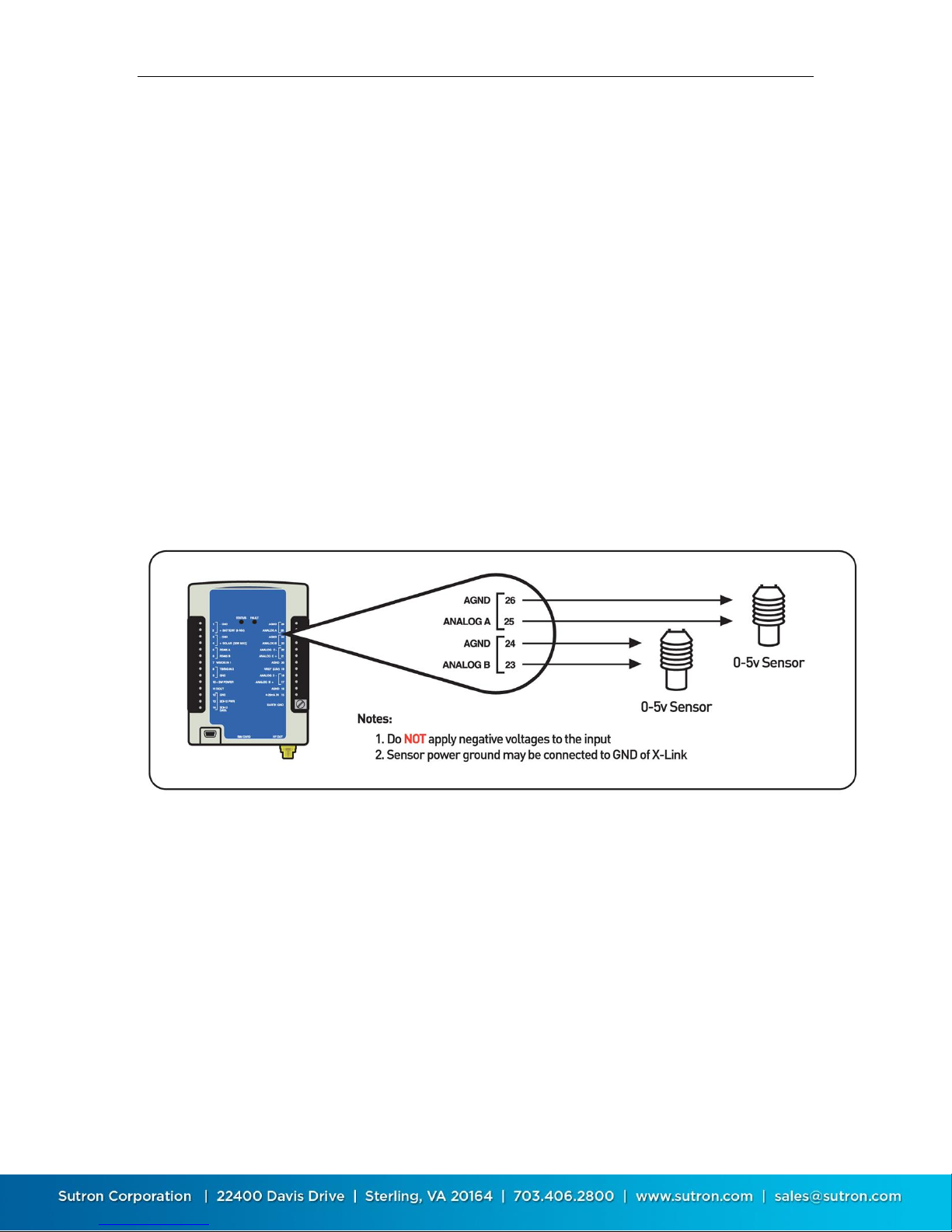
Sutron Corporation X-Link Operations & Maintenance Manual, Rev 1.63 5/24/2016 pg. 81
output into environmental units can be done via slope and offset for simple
sensors, and via equations for non-linear sensors.
7.1.4.10. Analog Type
This setting directs the input channel to which the sensor should be connected
and the type of analog measurement to make. These options are available
0-5V A
0-5V B
Diff C
Diff D
4-20 mA
7.1.4.11. 0-5V A and 0-5V B
Connection A: 0-5V A Terminal #25 and AGND Terminal #26
Connection B: 0-5V B Terminal #23 and AGND Terminal #24
Inputs 0-5V A and 0-5B are designed to be general purpose 0-5 Volt DC input.
While sometimes referred to as a single ended input, it is designed to measure
voltage with respect to analog ground. These inputs have a high impedance (>2
Meg Ohms) and will not load down or draw significant current. The input range is
0V to 5V. Negative voltages with respect to AGND may NOT be measured on
these inputs.
To connect a sensor:
The voltage output by the sensor should be connected to either A or B.
The analog ground from the sensor needs to be connected to AGND.
Page 82
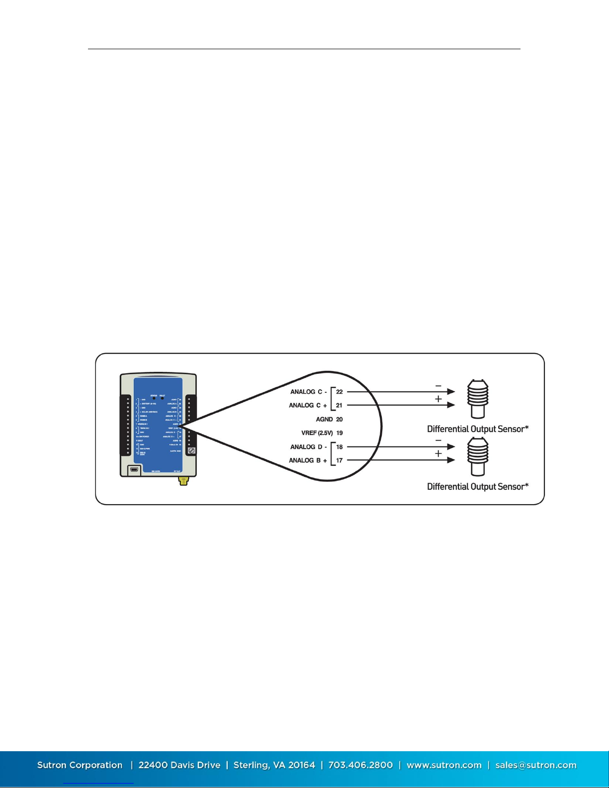
Sutron Corporation X-Link Operations & Maintenance Manual, Rev 1.63 5/24/2016 pg. 82
The sensor will likely require power – connect that to VREF if 2.5V is
appropriate or to +SW POWER which is 12V (or whatever power X-Link is
supplied with). Make sure to set up the warmup (the amount of time to
power the sensor before reading its output) as required by the sensor.
If the sensor has a power ground, connect that to AGND.
7.1.4.12. Diff C, Diff D
Connection: Diff C (Terminal #21 and #22)
Connection: Diff D (Terminal #17 and #18)
Optional connection to VREF (#19) and AGND (#16 and #20) as needed
Measurements Diff C and Diff D are designed to operate with a special type of
analog output found on many sensors that use a bridge configuration or any
sensor that outputs a very small voltage. This input type has a + and - input that
connects to the sensor output.
Typically, a bridge sensor will be powered on VREF (sometimes referred to as
excitation), have a signal + and signal –, and provide a wire for the analog
ground. NOTE: If after wiring the sensor, it displays a negative reading, you may
reverse the + and - leads coming from the sensor.
Page 83
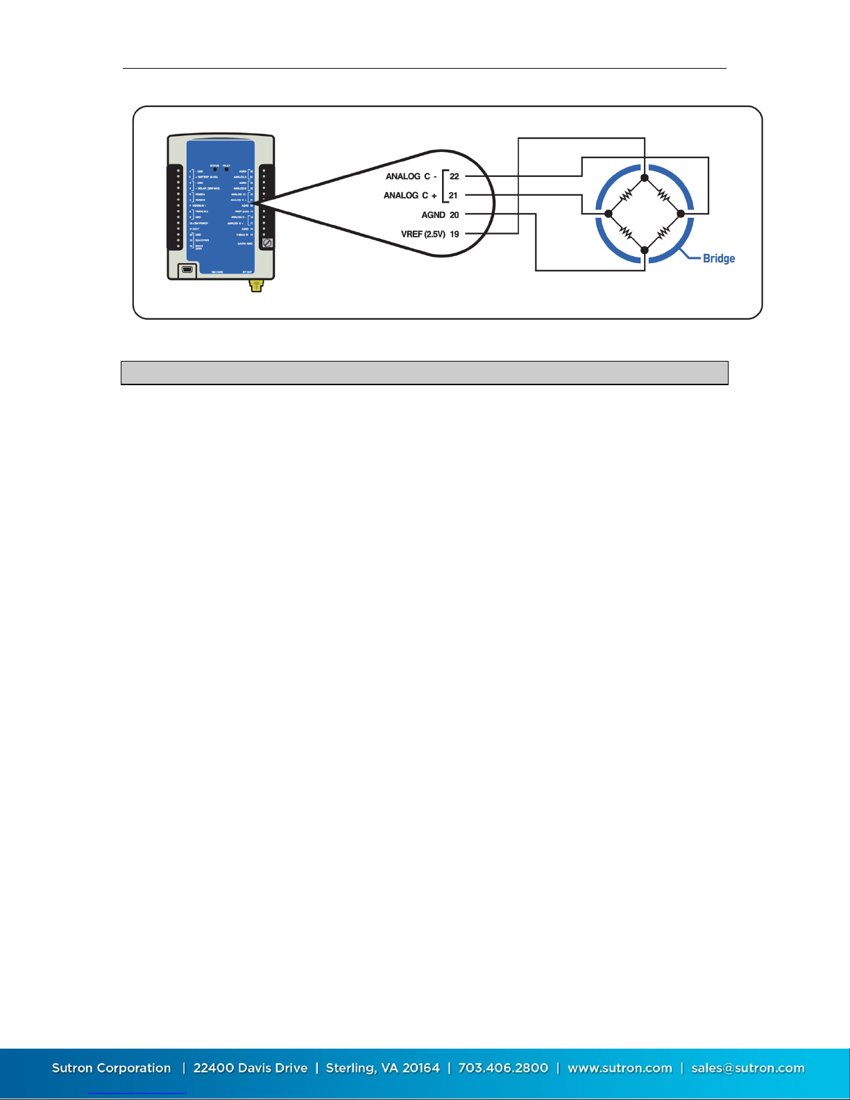
Sutron Corporation X-Link Operations & Maintenance Manual, Rev 1.63 5/24/2016 pg. 83
Reading Negative Output Voltages on Differential Inputs:
In limited cases, sensors with negative outputs may be used on the differential
inputs with the following limitations:
1) The negative line from the sensor must not connect to the digital ground of
the sensor with the sensor making a ground connection to the ground
(including antenna ground) of the X-Link logger. (i.e. the sensor outputs
must be able to be floated with respect the grounding of the sensor itself)
2) The negative voltage (or positive voltage) must remain within the range of
the differential input range selected.
3) The common mode input range of the differential inputs must not be
exceeded.
While the differential inputs are capable of reading negative voltages, it is
important to keep the voltages with respect to ground within in the common
mode input range of 0.5 to 3.7 volts. In the case of a bridge sensor, by using the
vref and agnd to establish the voltage on the network, you are assured of having
a positive voltage with respect to agnd. In the case of the bridge, you simply
need to remain within the voltage range selected (see 6.1.4.12 below) and
simultaneously remaining in the common mode range of the inputs or 0.5 volts
to 3.7 volts.
The diagram below shows how to make such a connection:
Page 84
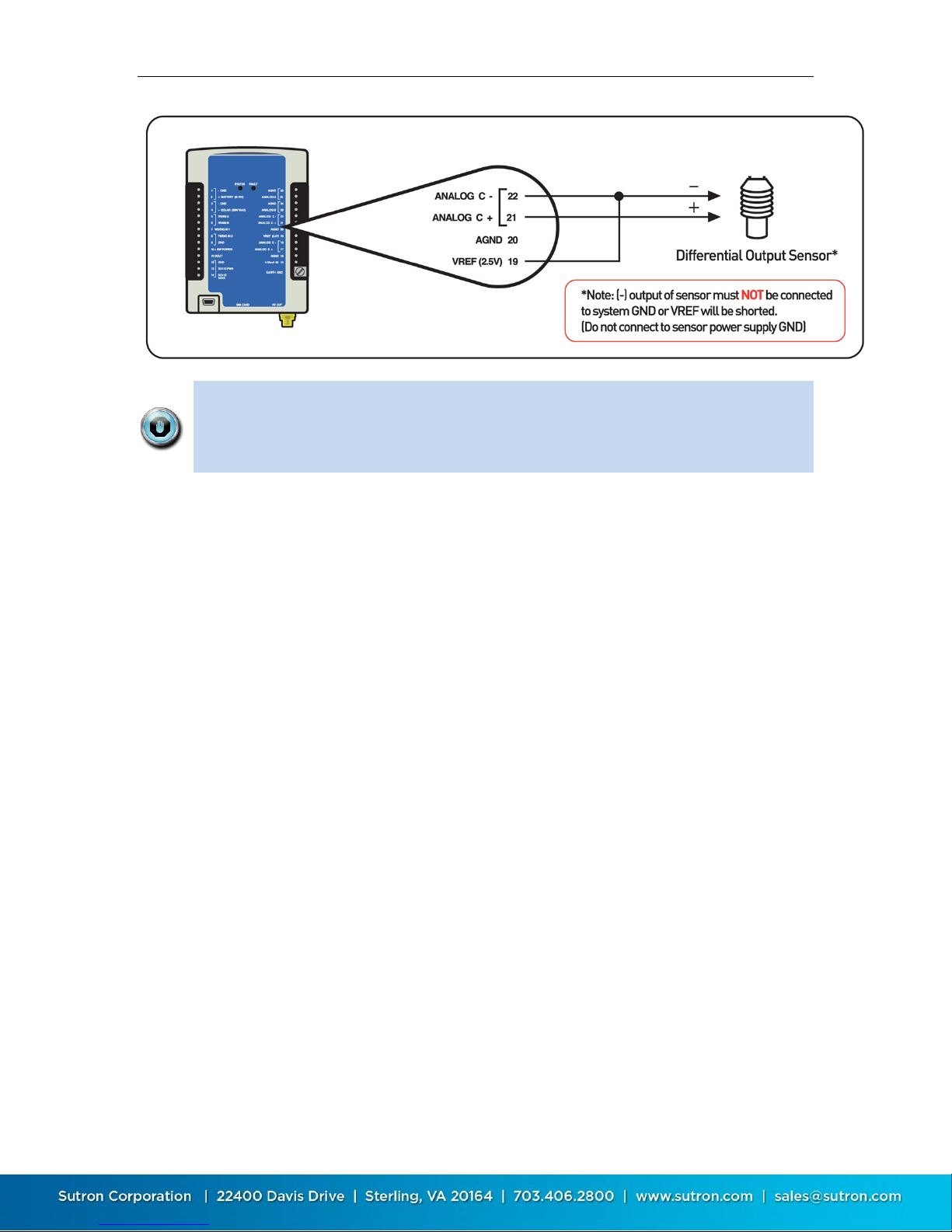
Sutron Corporation X-Link Operations & Maintenance Manual, Rev 1.63 5/24/2016 pg. 84
The common mode voltage for differential sensors is 0.5V to 3.7V. If the sensor
is floating, it should be tied to VREF and not to AGND in order to maintain this
common mode voltage. Sensors that are not powered by X-Link are generally
floating (such as a pyranometer).
7.1.4.13. Input Range
This setting is relevant only to analog differential measurements. Remember
that the system must read a voltage that falls into the common mode range
mentioned in the above note. Voltages that are negative with respect to the
AGND terminal may not be measured. The following options are available:
-39 to +39mV
-312 to +312mV
-2.5 to +2.5V
Choose the option that is close to and greater than the input range of the sensor
that is being connected.
For example, if a sensor provides a reading from 0 to 100mV, choose the 312mV
option. If you were to choose the 39mV option, when the sensor provided a
reading greater than 39mV, the unit would indicate a sensor failure.
7.1.4.14. 4-20 mA
Connection: 4-20ma IN (Terminal #15 and #16)
This input is designed to function with sensors that have a 4 to 20ma current
loop interface. This type of interface is superior to voltage outputs when the
cables to the sensors must travel a long distance or when the equipment is
located in electrically noisy environments. X-Link will measure the current
flowing when connected to the 4-20ma Input. Typical 4-20ma sensors will give a
4 to 20ma current for a 0 and 100% FS. Readings that are greater than 21mA will
be considered a fault. The current required for the sensor is provided by the 2
wire loop and does not typically require additional connections.
Page 85

Sutron Corporation X-Link Operations & Maintenance Manual, Rev 1.63 5/24/2016 pg. 85
NOTE: X-Link does not provide a dedicated power supply for 4-20ma sensors.
The sensor shall have its own supply or run off the 12 volt supply of X-Link.
While the internal 4-20 measurement is made using an accurate 100 ohm resistor,
the overall loop resistance is 200 ohms due to an additional 100 Ohms series
protection resistor. This means that a sensor at a full 20 ma current output,
approximately 4 volts should be allotted for overhead voltage. This is typically
not an issue when an external voltage source is provided to operate the sensor that
may be in the 18 to 24 volt range. However, if a 12.5 volt battery is used to
source the voltage for the sensor in the current loop, then only 8.5 volts will be
supplied to the sensor at max sensor current output. Therefore if a full 12 volts is
necessary for the sensor, an external loop supply will be necessary or alternately
the sensor may be wired to a single ended voltage input with the use of an
external 100 Ohm accurate and stable resistor also attached to the voltage input
port.
7.1.4.15. Warmup
Analog sensors are powered by X-Link via one of several outputs:
VREF (reference voltage) which provides 2.5V, terminal #19
Switched Power which provides whatever voltage is powering X-Link,
presumably 12V, terminal #10
Normally, these outputs are off. Prior to making an analog measurement, X-Link
will turn on these outputs. After that, X-Link waits Warmup amount of time
(which is expressed in seconds) before measuring the output of the sensors. This
Warmup time gives the sensors a chance to power up and prepare their outputs.
If Warmup is set to zero, X-Link will not wait at all prior to measuring. The value
Warmup should be set to depends on the analog sensor being measured.
Warmup is also used for Digital and SDI-12 type sensors. If a such a sensor (or
a wind sensor that uses digital or SDI-12 inputs) is set up with a warmup, then
VREF and Switched Power will both be turned on. If warmup is set to zero,
those output lines will not be turned on. This is different for Analog
measurements which turn on the lines regardless whether warmup is zero.
7.1.4.16. Battery
This type measures the voltage of the battery connection to X-Link. This
measurement is a useful diagnostic for tracking the performance of the battery
and any solar panel or other charging equipment.
7.1.4.17. Wind
X-Link supports a variety of wind sensors, including RM Young and Gill Ultrasonic
sensors. Any sensor that provides an analog, frequency, or SDI-12 output can be
handled by X-Link. RS-232 sensors are not supported.
Page 86

Sutron Corporation X-Link Operations & Maintenance Manual, Rev 1.63 5/24/2016 pg. 86
Wind sensors, sometimes referred to as anemometers, provide two readings:
wind speed and wind direction (sometimes referred to as azimuth). Wind speed
is expressed in units of velocity (mph, kph, etc), while wind direction is expressed
in degrees (0 to 360).
7.1.4.18. Wind Type
Each wind measurement can be one of the following
Wind Direction Analog
Wind Direction SDI-12
Wind Speed Frequency
Wind Speed Analog
Wind Speed SDI-12
Wind is unlike all the other measurements in that it is a combination of two
measurements: one setup for wind direction and the other setup for wind speed.
In order to correctly set up a wind sensor, two measurements must be set up.
One measurement must be wind speed, and the other wind direction. Set up the
measurements in order, for example, make measurement one a wind speed
sensor and measurement two a wind direction sensor.
Both the wind speed and the wind direction measurements must have the
following fields set up exactly the same:
Measurement Time
Measurement Interval
Averaging Time
Sampling Interval
If the fields are not set up exactly the same way, X-Link will show an error, Bad
Wind Setup.
Additional settings will appear based on the Wind Type chosen. Analog types will
allow the selection of analog input and warmup time. SDI-12 types will allow SDI12 command and parameters to be chosen.
7.1.4.19. Wind Averaging
This setting can be set to Scalar or Vector.
Scalar Speed:
o Mean Speed Scalar – This is the scalar wind speed, not taking direction
into account. The scalar average of 10mph for an hour and 20mph for an
hour is 15mph, regardless of changing direction.
Scalar Direction:
Page 87

Sutron Corporation X-Link Operations & Maintenance Manual, Rev 1.63 5/24/2016 pg. 87
o Mean Direction Unit – This is the wind direction (in degrees) not
weighted for wind speed. Here, the average of 10mph at 0 with 20mph
at 90 is 45.
Vector Speed:
o Mean Magnitude Wind – This is the vector average of the wind speed
which takes direction into account. Here, the average of 10mph at 0 for
1 hour and 20mph at 180 for 1 hour is negative 5mph.
Vector Direction:
o Mean Direction Wind – This is the wind direction (in degrees) weighted
for wind speed. Here, the average of 10mph at 0 with 100mph at 90 is
84.
The raw reading (the reading before slope, offset, and equation processing are
applied) is not available for wind measurements.
7.1.4.20. Digital
Use the setting Digital Type to tell X-Link what kind of sensor is connected.
7.1.4.21. Digital Type
X-Link supports the following digital types:
Level 1&2 (terminal 7&8)
Counter 1&2 (terminal 7&8)
Frequency 1&2 (terminal 7&8)
Period 1&2 (terminal 7&8)
Frequency and Period share the same input (terminal 12). Additionally, the RM
Young sensor type requires the use of this input too. Only one of these should be
set up at a time.
Frequency will have X-Link sample the input for 750ms. It will provide a result
that is the average frequency of the input during that time span. If no signals are
noticed on the input during the time, the measurement is considered bad.
10kHz is the maximum input frequency that X-Link supports.
When Period is the chosen type, X-Link will watch the input line for up to 10
seconds. X-Link stops watching as soon as one wave period is noticed on the
input. If the input signal does not transition during this time, the measurement is
considered bad.
Digital measurements also use the Warmup setting. If Warmup is not zero, then
switched power and VREF will be turned on during a Digital measurement. See
the section on analog measurement types for details on Warmup.
Page 88

Sutron Corporation X-Link Operations & Maintenance Manual, Rev 1.63 5/24/2016 pg. 88
Counter type readings may be optionally debounced for 3ms using the debounce
setting. The 3ms debouncing eliminates false counts from tipping buckets and
other devices with noisy switches.
Counter type readings may also be limited by a rollover value. With rollover set
to 0, the counter will increase until it reaches 4,294,967,296 (2^32). With
rollover set to a non-zero value, the counter will be reset to 0 when it exceeds
the rollover value. For example, if rollover is set to 9999, the counter will be set
to 0 on the next count.
Omega will allow the setup of multiple measurements on the same digital input.
For example, it is possible to setup both a tipping bucket rate and a tipping
bucket accumulation on the same input.
That being said, some setups that share digital inputs will yield unpredictable
results.
o Setting up any number of tipping bucket and counters on DIn2 with
debouncing will work well.
o Setting up a tipping bucket and counters without debouncing on DIn2 will
not work correctly as far as debouncing is concerned.
o Setting up a level measurement will work in combination with any other
measurement.
o Setting up multiple frequency and period measurements on the same
input will work as long as the measurements do not overlap.
o For frequency and period readings on the same input, one measurement
must finish before a second one starts for the readings to be correct.
o For frequency and period readings, omega will not hold up one
measurement until another completes.
o Overlapped frequency and period measurements are not consider a
meaningful setup.
o Setting up a frequency or period measurement on the same input as a
tipping bucket or counter will not work correctly.
If you want to measure both frequency and count from an input you will
need to either jumper it to both digital inputs and setup one measurement
for the counter (e.g. counter 1) and the other for a frequency (e.g. frequency
2) or set up the measurements as explained in Section 8.10.8.10
7.1.4.22. Meta
Meta measurements use the result of another measurement as their basis.
Usually, a Meta measurement is used to average results of another
measurement.
Page 89

Sutron Corporation X-Link Operations & Maintenance Manual, Rev 1.63 5/24/2016 pg. 89
7.1.4.23. Meta Index
This setting tells X-Link what other measurement this Meta measurement refers
to.
Why use meta measurements? If you had set up an hourly averaged
temperature measurement, a Meta measurement could be set up to be the daily
average of all those hourly readings.
Measurement M1 (used for Hourly Temperature)
Measurement Type: Analog
Analog Type: 0-5VA
Measurement Interval: 1 hour
Averaging Time: 1 hour
Sampling Interval: 1 second
Measurement M2 (used for Daily Temperature)
Measurement Type: Meta
Meta Index: 1 (meaning it refers to measurement M1)
Measurement Interval: 24 hours
Averaging Time: 24 hours
Sampling Interval: 1 hour
When scheduling meta measurements, take care that they occur at the same
time or after the measurement they reference. If the meta and the reference are
scheduled for the same time, X-Link will try to delay the meta measurement until
the reference completes.
7.1.4.24. Manual Entry
Manual entry measurement types allow the user to enter a reading manually.
That value becomes the reading of the measurement. X-Link will store the user
entered value in the Offset field.
To enter a manual entry reading, use LinkComm's Calibrate button.
7.1.4.25. Internal Temperature
Internal Temperature measurements use a temperature sensor installed inside
X-Link. Every X-Link comes with a built in temperature sensor. The reading
provided is in degrees Celsius. To convert from Celsius to Fahrenheit set the
slope to 1.8 and the offset to 32.
7.1.4.26. Accubar Pressure And Temperature
Sutron provides Accubar Barometric Pressure and Temperature sensors which
can be connected to X-Link via an internal connector.
By default, the sensors produce an atmospheric pressure reading in millibars and
a temperature reading in degrees Celsius. To convert them to other units, please
Page 90

Sutron Corporation X-Link Operations & Maintenance Manual, Rev 1.63 5/24/2016 pg. 90
use the Slope and Offset settings. Multiply millibars by 0.02952998 to get inches
of Mercury at 0C (inHg). Multiply millibars by 0.01450377 to convert to PSI.
Each Accubar reading takes a bit longer than one second to complete. If two
Accubar measurements coincide, a single sensor reading is made and the result
shared between all the measurements.
7.1.4.27. Seametrics Flow and Rate
Certain Seametrics flow meters may be connected to X-Link. Please see the
Seametrics section on page 109 for all details.
7.1.5. Alarm Settings
See the Alarms section for complete details on alarm settings. (page 64)
7.1.6. Transmission Data Content Settings
7.1.6.1. Tx Data Content
Tx Data Content tells X-Link which readings to include in the transmission. Each
measurement has the Tx Data Content setting.
The options are All, Individual, Last, and Exclude.
By selecting All, all the measurements that are logged are also set to be
transmitted. Only readings made since the last transmission are included.
This setting is dependent on the Log Interval setting.
Last means to transmit only the last logged value.
By selecting Exclude, no readings of this measurement are transmitted.
See Tx Data Time and Interval below for the Individual setting.
7.1.6.2. Tx Data Time And Interval
If Individual is selected for Tx Data Content, the fields Tx Data Time and Tx Data
Interval will appear, allowing the choice of what data to include in the
transmission.
This options should only be used to measure and log data more frequently than
to include it in transmissions. For example, if one wanted to measure and log
data once a minute, one would set the Measurement and Logging Intervals to
one minute. Since it may be expensive to transmit all that data, one can choose
to transmit only every 10th reading by setting the Tx Data Interval to 00:10:00.
The example below uses Measurement and Logging Intervals of 15 minutes. Tx
Data Content is set to Individual.
Timeline:
Page 91
Sutron Corporation X-Link Operations & Maintenance Manual, Rev 1.63 5/24/2016 pg. 91
11:00 measure and log data
11:15 measure and log data
11:30 measure and log data
11:45 measure and log data
11:50 transmission
Setup options:
The user could set up to transmit all four of those values.
o Tx Data Content = All
The user could set up to transmit the data from 11:15 and 11:45.
o TX Data Time = 00:15:00, Tx Data Interval = 00:30:00.
The user could set up to transmit only the data from 11:45.
o Tx Data Time=00:45:00, Tx Data Interval = 01:00:00.
The user could set up to transmit only the data from 11:00.
o Tx Data Time=00:00:00, Tx Data Interval= 01:00:00
Limitation: The user could NOT set up to transmit the data from 11:30 and
11:45
Tx Data Interval must be a multiple of the Logging Interval. Setting Logging
Interval to 15 minutes and Tx Data Interval to 20 minutes is not a good idea.
7.1.7. Measurement Setup Defaults
To change the setup of a single measurement to its defaults, type M1 SETUP
DEFAULT on the command line to reset measurement one. This will affect only
one measurement.
7.1.8. Measurement Calibration
X-Link offers an easy way to change the current reading of any measurement.
Press the Calibrate button on the Measurements tab in LinkComm and enter the
desired reading.
Via command line, type M1=10.5 to set the reading of measurement one to 10.5
This calibration procedure has the effect of modifying the measurement’s Offset.
When a sensor is calibrated, X-Link will log the readings before and after the
calibration along with a calibration event:
>M1 = 12
Measurement M1 STAGE set to 12.000
04/18/2012,13:19:49,STAGE,8.119
04/18/2012,13:19:49,Calibration,1
04/18/2012,13:19:49,STAGE,12.000
Page 92

Sutron Corporation X-Link Operations & Maintenance Manual, Rev 1.63 5/24/2016 pg. 92
7.1.9. Measurement Two-Point Calibration
Changing the slope and offset of a measurement can be accomplished by using
the automated two point calibration. You will need to be able to affect the
sensor so that it can provide two different readings.
On the command line, type M1 CAL. This procedure requires that the sensor be
placed so that it provides one known value, then placed again to provide a
different known value. This procedure will affect both Slope and Offset of a
measurement.
7.1.10. Multiple Measurements Using the Same Sensor
You can set up multiple measurements with the same input. For example, to log
the daily rainfall and the rainfall during the last hour, set up two measurements:
one a precipitation rate with an interval of one hour, and another as
precipitation rate with an interval of one day.
To log the daily temperature and the hourly temperature, only one physical
temperature sensor is needed. Set up two measurements with the same setup;
change the Measurement Interval and the Averaging Time and use a different
Label for each. One would happen once a day (Measurement Interval 24 hours,
Averaging Time 24 hours), and the other once an hour (Measurement Interval 1
hour, Averaging Time 1 hour). It would be a good idea to set up the sampling
Interval to one minute for both sensors in order to save power (See page 70).
If two separate measurements are scheduled to measure the same sensor at the
same time (as they will in the examples above), only one reading of the sensor is
made and the result is shared by both measurements.
7.2. Telemetry Setup
7.2.1. Common Telemetry Setup
Regardless of the type of communication device installed in the X-Link, the
following telemetry settings are relevant.
Names and descriptions of each telemetry setup field are below. The
abbreviation Tx refers to transmission.
7.2.1.1. Tx Enable
Enables scheduled (sometimes called self-timed) transmissions. If this setting is
enabled, X-Link will periodically deliver sensor data to the designated
destination. If disabled, X-Link will not initiate any scheduled transmissions.
Page 93
Sutron Corporation X-Link Operations & Maintenance Manual, Rev 1.63 5/24/2016 pg. 93
If Tx Enable is disabled but Listening is on, X-Link will be able to receive
messages; GPRSLink, HSPALink, and CDMALink will be able to receive incoming
connections too.
Setting up your GPRSLink with Tx Enable disabled and Listening enabled is a valid
setup in which software like Sutron WIN may periodically get data from the
station.
7.2.1.2. Tx Time and Tx Interval
These variable controls when and how frequently scheduled transmissions are to
be made. Tx Enable must be on for these settings to be relevant.
The interval controls how often transmissions are made, and the time controls
when the transmission process is started.
Example: Time 00:00:00 interval 00:10:00
00:10:00 transmission process starts
00:20:00 transmission process starts
00:30:00 transmission process starts
and every ten minutes afterwards…
Example: Time 00:00:30 interval 00:05:00
00:00:30 transmission process starts
00:05:30 transmission process starts
00:10:30 transmission process starts
and every five minutes afterwards…
The transmission is not instantaneous. At the designated time, the
transmission process will start. That process includes formatting the data
content, powering on the modem, waiting for the modem to acquire a good
signal, etc.
Make sure to have the transmission scheduled a short while after the
measurements are completed. If the measurements happen at the 15 minute
mark, set the transmission time to 16 minutes to ensure the measurements are
completed before the transmission process starts.
For IRIDIUMLink and other X-Links set up to transmit messages, in order to
receive the freshest data, the Tx Interval should be set such that only one
transmission is sent at one time. Ideally, each message will be full. See the
section Optimizing Data Usage for more details.
7.2.1.3. Tx Format
The format controls what the data in the transmission looks like. Options are
Page 94

Sutron Corporation X-Link Operations & Maintenance Manual, Rev 1.63 5/24/2016 pg. 94
Pseudobinary B
Pseudobinary C
Pseudobinary D
CSV
SHEF
SHEFFIX
All formats will place all the required values for one measurement before
proceeding to the next. More recent readings go first.
The pseudobinary formats are fully described in Data Transmission Formats.
Pseudobinary is a relatively compressed ASCII data format that allows three
bytes for every sensor reading. Here is an example:
B1@@Gt@Gs@Sx@Sr@@i@@iI
The CSV format is an extremely verbose human readable format only suitable for
diagnostics. It's full name is Sutron Standard CSV and it is the same format that
X-Link's downloaded logs are in. Here is an example of the format:
09/14/2009,12:30:00,TEMP,28.5
09/14/2009,12:00:00,TEMP,29.0
09/14/2009,12:00:00,BATTV,13.53
09/14/2009,12:00:00,ANA,-7.5
SHEF and SHEFFIX formats are described in details in the Data Transmission
Formats section. The SHEF formats are ASCII and legible. They include the
measurement label, measurement interval, and age of the most recent reading
along with the sensor data. The example below illustrates the SHEF format:
:HG 0 #15 10.20 10.15 :PC 0 #15 50 49 :TA 0 #15 -22.1
-22.0 :VB 0 12.2
7.2.1.4. Tx Alarm Data
Tx Alarm Data helps set up the data content for alarm transmissions. The options
are Single Meas and All Meas.
If Alarm Data is set to All Meas, then alarm transmission data content will
contain the last reading from each active measurement.
When Alarm Data is set to Single Meas, the alarm transmission will only have the
reading that caused the alarm.
7.2.1.5. Retransmit
If enabled, Retransmit will cause X-Link to retry all missed transmissions at a
future date. Please see the Retransmissions section for details (page 50).
Page 95

Sutron Corporation X-Link Operations & Maintenance Manual, Rev 1.63 5/24/2016 pg. 95
7.2.1.6. Max Tx Time
The Max Tx Time setting dictates how long X-Link will continue to attempt to
make a transmission. The default value is 10 minutes. The goal of this setting is
to reduce power consumption when there is a transmission problem, such as no
network for cellular stations or no satellite view for Iridium stations.
This setting was introduced in version 1.57. Prior to that, X-Link would retry
from either 50% or 80% of the Tx Interval, depending on the X-Link model.
7.2.2. Cell Phone Settings
The following settings are used to set up GPRSLink, HSPALink, and CDMALink.
7.2.2.1. Tx Mode
If Tx Mode is set to Internet, X-Link will use the modem to get an internet
connection. Once the connection is established, X-Link will connect to the Main
Server in order to deliver data. Failing that, it will try the Backup Server.
If Tx Mode is set to SMS, X-Link will send transmission data via SMS (messages)
to up to three telephone numbers, as specified by SMS Tx Phone.
If Tx Mode is set to Internet Fallback SMS, and X-Link will first try to connect to
the Main Server. If that fails, it will try the Backup Server. If it cannot establish an
internet connection or if it cannot reach both servers, X-Link will deliver the
sensor data via SMS (text messages). The SMS will be sent to up to three
telephone numbers, as specified by SMS Tx Phone.
7.2.2.2. Main Server
When it is time to make a scheduled transmission, if Tx Mode is set to Internet or
Internet Fallback SMS, X-Link will connect to the destination specified by Main
Server. The server may be expressed as a name (such as www.sutronwin.com) or
an IP address (such as 10.0.0.1).
See the section called TCP/IP Session for details on the connection. (page 153)
7.2.2.3. Backup Server
If X-Link is unable to connect to the Main Server, but it does have an internet
connection, it will try to deliver data to the Backup Server.
7.2.2.4. Server Port
What TCP/IP port to connect to on the Main and Backup Servers.
7.2.2.5. Server Password
If the Main and Backup Servers are protected by a password (sometimes called a
shared secret), it must be entered in this field. If it is not, X-Link will not be able
to deliver sensor data.
Page 96

Sutron Corporation X-Link Operations & Maintenance Manual, Rev 1.63 5/24/2016 pg. 96
7.2.2.6. SMS Tx Phone A
See Below.
7.2.2.7. SMS Tx Phone B
See Below.
7.2.2.8. SMS Tx Phone C
When it is time to make a scheduled transmission, if Tx Mode is set to SMS, XLink will send data to the phone number(s) set up in SMS Tx Phone.
Additionally, if Tx Mode is Internet Fallback SMS, and X-Link fails to get an
internet connection or it fails to connect to the Main and Backup Servers, X-Link
can send transmission data to phone numbers in SMS Tx Phone.
If you want data delivered to just one phone, enter it into SMS Tx Phone A, and
leave SMS Tx Phone B and C blank. To deliver to a second phone number, enter
the number in SMS Tx Phone B. Use SMS Tx Phone C to deliver data to a total of
three different numbers.
7.2.2.9. SMS Notify
SMS (text messages) will be sent when certain events such as station power on
occur to numbers listed in SMS Notify Phone.
7.2.2.10. SMS Notify Phone A
See Below.
7.2.2.11. SMS Notify Phone B
If not blank, event notification SMS will be sent to these numbers. These fields
are relevant only if SMS Notify is enabled. To have notifications sent to only one
phone, enter the phone number into SMS Notify Phone A, and leave SMS Notify
Phone B blank. To deliver to a total of two phone numbers, enter a second
number in SMS Notify Phone B.
7.2.2.12. Listening
Controls whether GPRSLink will keep the modem on all the time. The benefit of
turning Listening enabled is that GPRSLink will be able to quickly respond to
incoming connections and/or SMS messages. The drawback is higher power
consumption. If Listening is disabled, GPRSLink will check for messages when it
makes a transmission.
7.2.2.13. SMS Listening Only
When SMS Listening Only is enabled, GPRSLink will NOT keep a TCP/IP port open.
Instead, it will only be listening for incoming SMS messages. Select this option if
you do NOT want the station to connect to the internet.
Page 97

Sutron Corporation X-Link Operations & Maintenance Manual, Rev 1.63 5/24/2016 pg. 97
If SMS Listening Only is disabled, GPRSLink will always be connected to the
internet. It will keep a TCP/IP listening socket open on the Listen Port. Programs
like LinkComm, HyperTerminal, Sutron WIN, can get in touch with X-Link
immediately in order to download data, change setup, or perform any other
activity.
7.2.2.14. Listen Port
What TCP/IP port to listen on for incoming connections. This setting is only
relevant if Listening is enabled and SMS Listening Only disabled.
7.2.2.15. APN name
This is the service provider's APN (Access Point Name). It Is required for station
to use the internet. If this field is not set up, GPRSLink will report the error, No
Data Service.
7.2.2.16. Modem username
See Below.
7.2.2.17. Modem password
Some providers require that a user name and password be provided in order to
connect to the internet.
7.2.2.18. SIM PIN
Some SIM cards are locked with a PIN. This setting holds the value to give to the
SIM when turning the modem on. A locked SIM will not work without a PIN and
GPRSLink will report Bad PIN.
7.2.2.19. Init String
This is a set of AT commands that can be sent to modem on boot up. Separate
multiple commands with ;
7.2.3. Iridium Settings
7.2.3.1. Listening
If Listening is enabled, IRIDIUMLink keeps the communication device powered
on all the time. This will allow the immediate reception of any messages sent to
IRIDIUMLink. However, it will also increase the power usage. If disabled,
messages get checked every time a scheduled transmission is made.
7.2.3.1. Local Time Offset
The Iridium satellite system provides IRIDIUMLink with the correct time. That
time is UTC. The Local Time Offset may be used to change the station's clock to a
different time zone.
Page 98

Sutron Corporation X-Link Operations & Maintenance Manual, Rev 1.63 5/24/2016 pg. 98
The time may be initially set using the Set Clock button on the diagnostic tab to
ensure it is close to the time desired, otherwise, the time will be UTC until it
does the clock sync at the next transmission.
7.3. Other Setup
These fields relate to general station setup.
7.3.1.1. Station Name
User set identifier for the station.
7.3.1.2. Recording
Recording is the act of collecting and logging sensor data. If recording is off, XLink is idle and will not make any automatic measurements. If recording is on, XLink is active and collecting sensor data according to its setup.
LinkComm provides a button to start recording, or stop recording. To change
recording via command line, type RECORDING = ON or RECORDING = OFF.
7.3.1.3. Log Daily Values
X-Link can log diagnostic information at 23:59:59 each day. That information
consists of battery voltage and telemetry accounting, such as the number of
transmissions made and the number of bytes transmitted. To prevent this data
from being logged, disable the Log Daily Values setting located on the Other
Setup tab of LinkComm.
7.3.1.4. Auto Output
When X-Link has Auto Output mode enabled (via front panel, Station
Setup>Other Settings>Auto Output, command line AUTO OUTPUT), it will
automatically send data out on the USB port. Using LinkComm's Terminal
window, type EXIT to leave command line mode and to capture the auto output.
X-Link will output data of every active measurement when it is measured
according to the user set Measurement Interval and Time. For example, if you set
up a battery voltage reading to be made once every minute, auto-output will
place fresh battery data on the port once a minute. If multiple measurements
are active, they will all be output every time new data is available for any
measurement.
The data output is ASCII. This is an example of the output for two
measurements:
46.3, 33.2
46.3, 33.0
46.4, 32.1
46.4, 30.0
Page 99

Sutron Corporation X-Link Operations & Maintenance Manual, Rev 1.63 5/24/2016 pg. 99
7.3.1.5. Output1
X-Link features a digital output labeled DOUT. X-Link can automatically activate
the output. See the Output section for details (page 120.)
7.3.1.6. Modbus
All Modbus settings are described in the Modbus section (page 169).
7.3.1.7. Setup Defaults
Selecting this option restores the unit’s factory defaults. This is a complete
erasing of the setup. All measurement and telemetry setup will be lost. The
status will also be cleared. This option does not erase the log.
Reset the station to defaults using LinkComm's Setup Default button on the
Diagnostic tab or via command line by typing SETUP DEFAULT.
Page 100
Sutron Corporation X-Link Operations & Maintenance Manual, Rev 1.63 5/24/2016 pg. 100
RM Young Output
X-Link input
AZ SIG
Analog 0-5V (either A or B)
WS SIG
WS/DIG IN1
REF
AGND
+V SUPPLY
+SW POWER
AX EXC
VREF
Wind Speed Setup
Value
M1 Active
On
Label
WNDSPD
Meas Type
Wind
Wind Type
Wind Speed Freq
Warmup
1 sec
Averaging Time
00:00:10
Sampling Interval
1.0 sec
Slope
Depends on desired units – see below
Wind Speed Units
Slope
m/s
0.098
knots
0.1904
mph
0.2194
kph (km/h)
0.3528
Wind Direction Setup
Value
M2 Active
On
Label
WNDDIR
Meas Type
Wind
8. Measurement Setup Examples
8.1. RM Young Wind Speed and Direction
This section describes how to connect the sensor and how to set up X-Link in
order to measure wind speed and direction. The sensor used is an RM Young
05103-11 which has a four-blade propeller for speed and a vane for direction.
The sensor provides a square wave signal for wind speed and uses a
potentiometer for wind direction.
This device provides wind speed via a frequency output and direction via an
analog output. To wire it up, connect like so:
A 1.0 MOhm resistor needs to be placed from VREF (or AGND) to AZ SIG. This
ensures that the value always goes to 355 (or 0 with AGND) when the
potentiometer is in the open region.
This X-Link setup will measure wind data from the RM Young:
 Loading...