

SUTO iTEC S435 Instruction And Operation Manual
English
Instruction and operation manual
S435
Vortex flow meter for saturated steam

n
Dear Customer,
Thank you for choosing our product.
Please read this manual in full before you start up the device and
carefully observe instructions stated in this manual. The manufacturer
cannot be held liable for any damage that occurs as a result of nonobservance or non-compliance with this manual.
Should the device be tampered with in any manner other than a
procedure that is described and specified in the manual, the warranty is
cancelled and the manufacturer is exempt from liability.
The device is designed exclusively for the described application.
SUTO offers no guarantee for the suitability for any other purpose.
SUTO is also not liable for consequential damage resulting from the
delivery, capability or use of this device.
2 S435

Table of Contents
1 Safety instructions......................................................................5
2 Application.................................................................................8
3 Technical data.............................................................................8
3.1 General.......................................................................................8
3.2 Electrical data..............................................................................8
4 Dimensional drawing...................................................................9
5 Installation ..............................................................................10
5.1 Installation requirements.............................................................10
5.2 Installation instructions...............................................................12
5.2.1 Error between the inner diameters of the pipes......................12
5.2.2 Straight pipe requirements..................................................12
5.2.3 Wafer type vortex flow meter installation diagram ..................14
5.2.4 Flange and bolt..................................................................15
5.3 Electrical connection....................................................................15
5.3.1 Requirements on cable........................................................15
5.3.2 Terminal connection ...........................................................16
5.4 Power supply connection..............................................................17
5.5 Frequency output.......................................................................17
5.6 RS485 communication ................................................................18
6 Parameter setting operation........................................................19
6.1 Keypad and display.....................................................................19
6.2 Parameter setting function and operation.......................................20
6.3 Operation menu.........................................................................21
6.4 Quick setup menu list .................................................................23
6.5 Parameter settings instruction......................................................24
6.5.1 Nominal Size......................................................................24
6.5.2 Flow Unit...........................................................................24
6.5.3 LowFlow Cutoff...................................................................24
6.5.4 Flow Range........................................................................24
6.5.5 Language..........................................................................24
6.5.6 Output Mode......................................................................24
6.5.7 Output Freq.......................................................................24
6.5.8 CommAddress ...................................................................25
6.5.9 Band Rate.........................................................................25
6.5.10 CompensMode .................................................................25
6.5.11 CompSetTemp..................................................................26
6.5.12 CompSetPress..................................................................26
6.5.13 RTD Sel...........................................................................26
6.5.14 PressMax.........................................................................26
6.5.15 VoltageMin/ VoltageMax/ Sensor Type..................................26
6.5.16 AtmSet............................................................................27
S435 3

n 1 Safety instructions
6.5.17 TP Show..........................................................................27
6.5.18 Press Unit........................................................................27
6.5.19 Press Cut Off....................................................................27
6.6 Instrument on-site debugging.......................................................27
6.7 Total reset................................................................................. 27
6.8 Communication mode selection.....................................................27
6.9 Temperature and pressure compensation function...........................28
7 Troubleshooting .......................................................................29
8 Disposal or waste......................................................................30
9 Warranty..................................................................................30
10 Appendix: Flow measurement range..........................................32
4 S435

1 Safety instructions
1 Safety instructions
Please check if this instruction manual accords with the
product type.
Please observe all notes and instructions indicated in this
manual. This manual contains essential information that must
be observed before and during installation, operation and
maintenance. Therefore this manual must be read carefully by the
technician as well as by the responsible user or qualified personnel.
This instruction manual must be available at the operation site of the
product at any time. In case of any obscurities or questions regarding
this manual or the product, please contact the manufacturer.
WARNING!
Compressed air!
Any contact with quickly escaping air or bursting
parts of the compressed air system can lead to
serious injuries or even death!
• Do not exceed the maximum permitted pressure range (see
sensors label).
• Use only pressure-tight installation material.
• Prevent persons from being hit by escaping air or bursting parts of
the instrument.
• The system must be pressureless during maintenance work.
WARNING!
Voltage used for supply!
Any contact with energized parts of the device may
lead to an electrical shock which can lead to serious
injuries or even death!
• Consider all regulations for electrical installations.
• The system must be disconnected from any power supply during
maintenance.
• Any electrical work on system is allowed only by authorized
qualified personal.
S435 5
n 1 Safety instructions
ATTENTION!
Permitted operating parameters!
Observe the permitted operating parameters. Any
operation beyond these parameters can lead to
malfunctions and may lead to damage on the product
or the system.
• Do not exceed the permitted operating parameters.
• Make sure that the product is operated under its permitted
conditions.
• Store and operate the product at the permitted temperature and
pressure.
• The product should be maintained and calibrated frequently, at
least annually.
General safety instructions
• It is not allowed to use the product in explosive areas.
• Please observe the national regulations before and during
installation and operation.
Remarks
• It is not allowed to disassemble the product.
• Always use spanners to mount the product properly.
ATTENTION!
Measurement values can be affected by malfunction!
The product must be installed properly and
maintained frequently. Otherwise it may lead to
wrong measurement values, which can lead to
wrong results.
• Always observe the direction of the flow when installing the
device. The direction is indicated on the housing.
• Do not exceed the maximum operation temperature at the sensors
tip.
• Avoid condensation on the sensor element because it will affect
accuracy enormously.
6 S435

1 Safety instructions
Storage and transportation
• It is recommended to use the packaging that comes with the
product for storage and transportation.
• Make sure that the storage temperature is between -10 ... +65°C.
The ideal temperature and humidity range is 25°C and 65%.
• Avoid direct UV and solar radiation during storage.
• The storage humidity must be between 5 … 90% with no
condensation.
S435 7
n 2 Application
2 Application
The S435 vortex flow meter operates on the Karman Vortices principle,
and is used to measure flow rates in saturated steam applications.
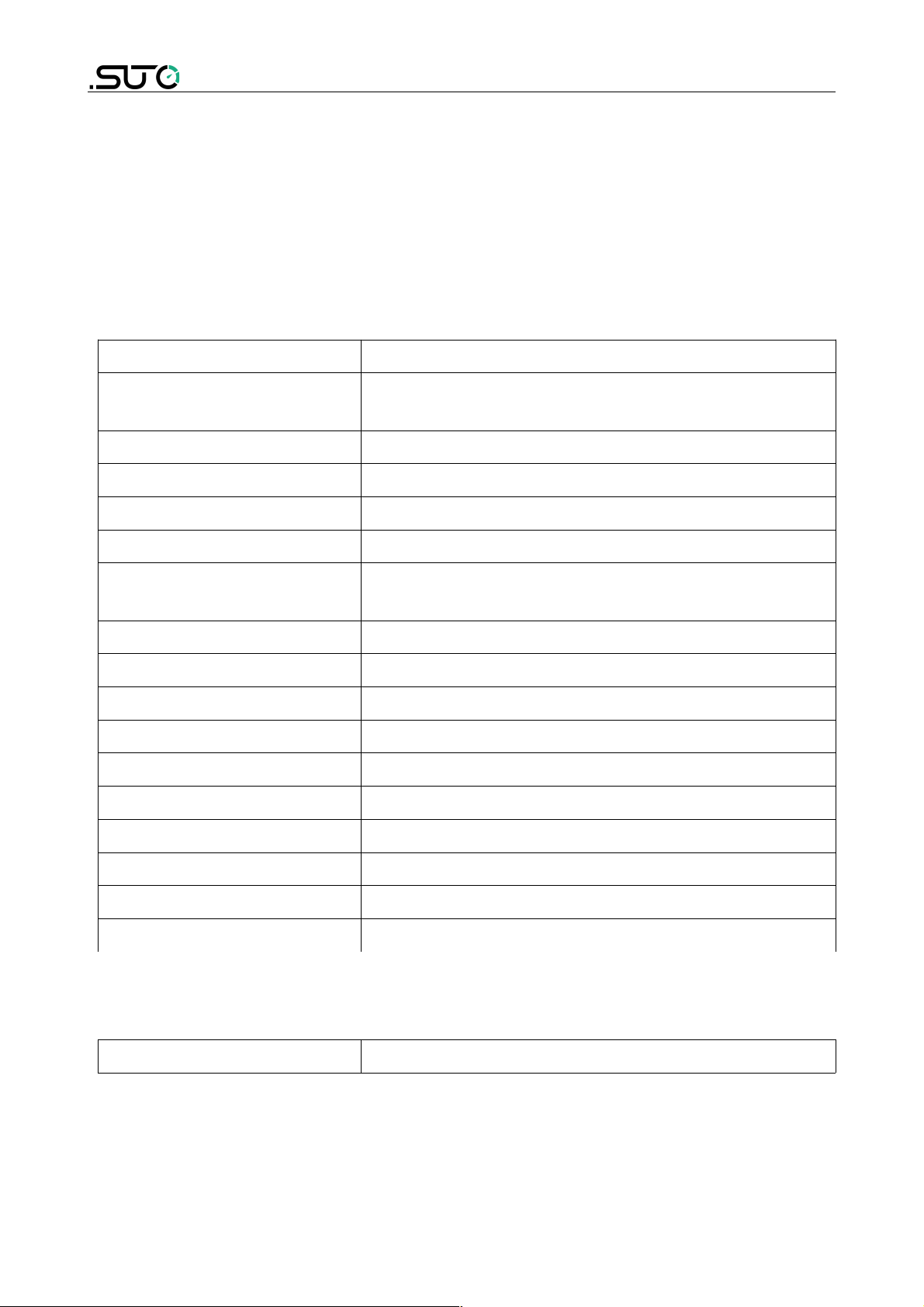
3 Technical data
3.1 General
Measured fluid Steam Gas
Nominal
diameter(mm)
DN40 … DN300 wafer type
Medium temperature -40 … +250°C
Ambient temperature -10 … +60°C
Accuracy ±1.5%
Repeatability 0.5%
Display Instant flow rate / Total flow rate
/ Frequency / Percentage of flow range
Signal output Pulse output / Modbus
Protection level IP65
Electrical connection 1/2" -14NPT
Installing type Wafer type
Wetted parts material 304 stainless steel
Process control material Carbon steel /304/316/316L(Flange/Wafer)
Detector probe 316 Stainless steel
Connecting rod 304 Stainless steel
Radiator Aluminium alloy
Range ratio 10:1
3.2 Electrical data
Power supply 24 VDC
8 S435
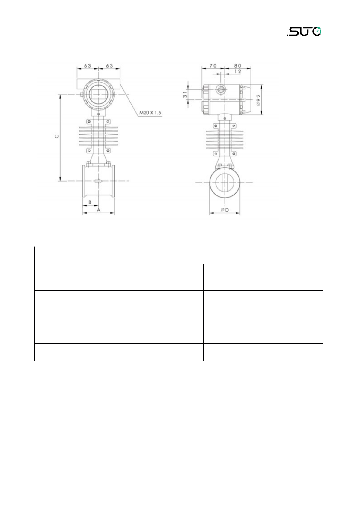
4 Dimensional drawing
4 Dimensional drawing
Figure 1 Water Vortex flow meter outline dimensional drawing
DN
Vortex Flow Meter Dimension Rated Pressure 1.6MPa
Unit: mm
A B C ΦD
40 100 50 256 75
50 110 55 256 87
65 110 55 262 109
80 110 55 267 120
100 120 60 271 149
125 133 73 291 175
150 160 90 304 203
200 185 115 331 259
250 210 140 357 312
300 240 165 383 363
S435 9

n 5 Installation
5 Installation
Please make sure that all components listed below are included in your
package.
Qty Description Item No.
1 S435 flow meter S695 435X *
* Note: X denotes the last digit,
which varies with pipe sizes
1 Companion flange with bolt
and gasket included
No P/N
1 Calibration certificate No P/N
1 Instruction manual No P/N
5.1 Installation requirements
Ensure the following when installing the product:
• The flow direction should match the arrow direction on the flow
meter.
• The flange bolts have been fastened to the max torque rating.
• Mechanical stress (twist and bent) should not exist when
installation. Mating flanges should keep axial symmetrical and
parallel, and proper gaskets should be used.
• Gaskets should not be extended to the flow area, otherwise
whirlpool generated and affecting accuracy of the flow meter.
• Any force and moment from the pipe should not affect the flow
meter.
• The display of the flow meter should face the users.
• Protecting plug of the cable entries are only allowed to be removed
when wiring.
• Remotely installed sensors should be mounted on places that is
almost vibration-free.
• Converter of the flow meter should be free from direct sunshine.
(Shade is required)
Observe the following rules when choosing the installation places:
• No negative pressure in measuring tube;
• Avoid being installed near motor, transformer, and other strong
10 S435
5 Installation
current equipment, to avoid jammer;
• Avoid being installed near strong corrosion gas;
• Avoid being installed in separated place, when measuring mixed
fluid;
• Avoid being under direct sunlight, ambient temperature should be
-25 … +65 ;℃
• Choose places without or with less vibration. If too much vibration,
install fixed support before and after the pipe;
• Relative humidity is 5% … 90%;
• Avoid direct rain and soaked places.
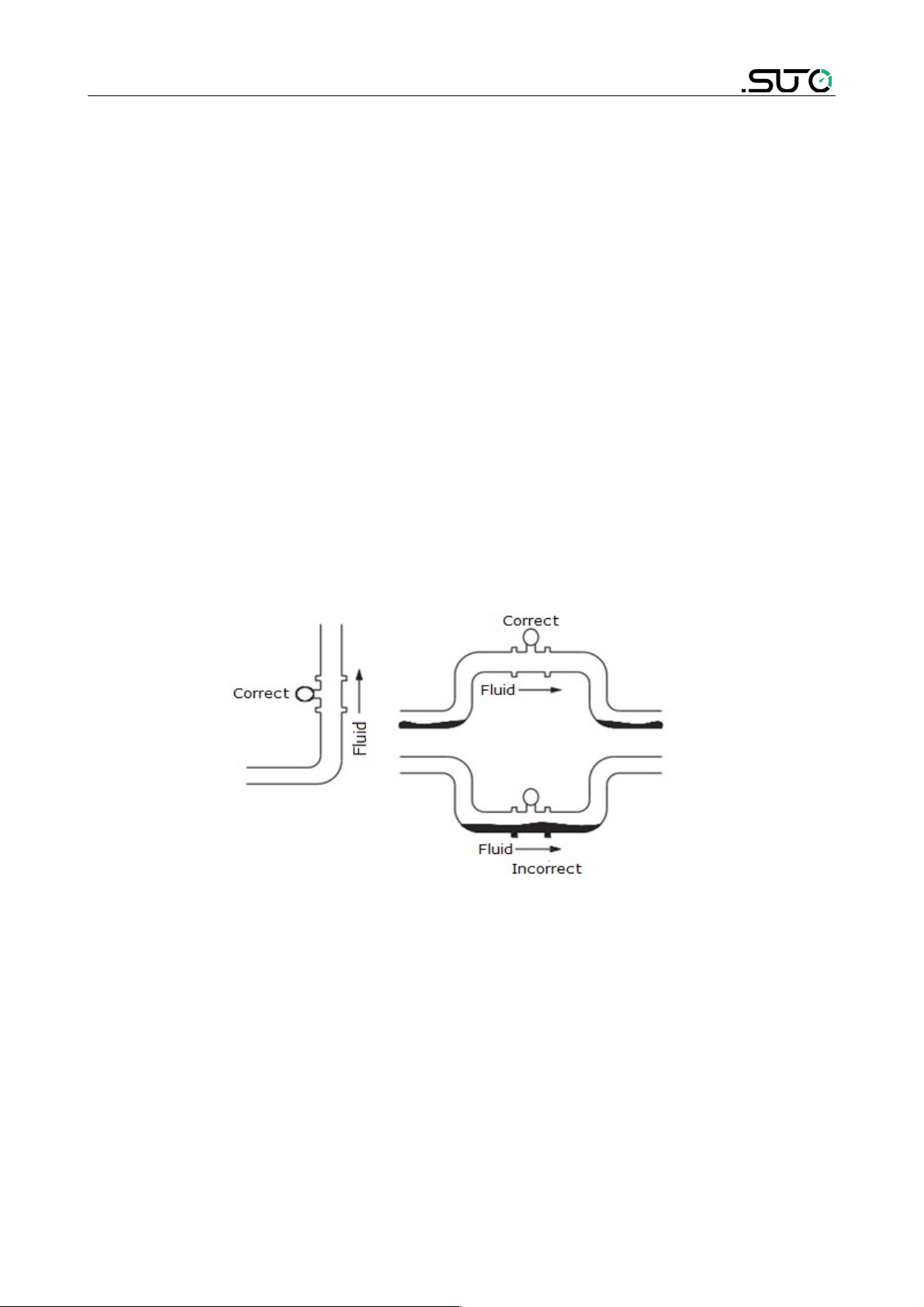
• Prevent liquid retention.
• The flow meter should be mounted on a vertical pipe to prevent
accumulation of fluid.
• When the flow meter is installed horizontally, raise the pipe section
installed with the flow meter.
S435 11
 Loading...