


English
Instruction and operation manual
S 600
Portable compressed air purity analyzer

Dear Customer,
Thank you for choosing our product.
Please read the operating instructions in full and carefully observe them
before starting up the device. The manufacturer cannot be held liable
for any damage which occurs as a result of non-observance or noncompliance with this manual.
Should the device be tampered with in any manner other than a
procedure which is described and specified in the manual, the warranty
is cancelled and the manufacturer is exempt from liability.
The device is designed exclusively for the described application.
SUTO offers no guarantee for the suitability for any other purpose.
SUTO is also not liable for consequential damage resulting from the
delivery, capability or use of this device.
2 S 600

Table of contents
1. Safety instructions.......................................................................4
2. Application.................................................................................8
3. Features.....................................................................................8
4. Technical data.............................................................................9
4.1 General data..........................................................................9
4.2 Electrical data .....................................................................10
4.3 Accuracy..............................................................................10
5. Dimensions...............................................................................11
6. Installation on site.....................................................................14
6.1 Installation requirements.......................................................14
6.2 Connection with the optional isokinetic sampling device.............17
6.3 Connection without the isokinetic sampling device....................18
6.4 Electrical connections............................................................19
6.5 Compressed air connections (inlet and outlet)..........................20
7. Setup and configuration.............................................................22
8. Operation.................................................................................22
8.1 Value view...........................................................................23
8.2 Graphic view........................................................................24
8.3 Main menu...........................................................................24
8.3.1 Files..............................................................................25
8.3.2 Service Info ...................................................................25
8.3.3 System Setting...............................................................26
8.4 Icons in the status bar...........................................................27
9. Guided measurement.................................................................27
9.1 Steps for guided measurement...............................................29
9.2 Reports for guided measurements...........................................33
10. Optional accessories.................................................................34
11. Maintenance............................................................................34
12. Disposal or waste.....................................................................34
13. Warranty................................................................................34
S 600 3

1. Safety instructions
1. Safety instructions
Please check if this instruction manual accords to the
product type.
Please observe all notes and instructions indicated in this
manual. It contains essential information which must be
observed before and during installation, operation and
maintenance. Therefore this instruction manual must be read carefully
by the technician as well as by the responsible user / qualified
personnel.
This instruction manual must be available at the operation site of the
flow sensor at any time. In case of any obscurities or questions,
regarding this manual or the product, please contact the manufacturer.
WARNING!
Compressed air!
Any contact with quickly escaping air or bursting
parts of the compressed air system can lead to
serious injuries or even death!
• Do not exceed the maximum permitted pressure range (see
sensors label).
• Only use pressure tight installation material.
• Avoid that persons get hit by escaping air or bursting parts of the
instrument.
• The system must be pressure less during maintenance work.
• WARNING!
• Voltage used for supply!
• Any contact with energized parts of the
product, may lead to a electrical shock which
can lead to serious injuries or even death!
• Consider all regulations for electrical installations.
• The system must be disconnected from any power supply during
maintenance work.
4 S 600

1. Safety instructions
WARNING!
Permitted operating parameters!
Observe the permitted operating parameters, any
operation exceeding this parameters can lead to
malfunctions and may lead to damage on the
instrument or the system.
• Do not exceed the permitted operating parameters.
• Make sure the product is operated in its permitted limitations.
• Do not exceed or undercut the permitted storage and operation
temperature and pressure.
The product should be maintained and calibrated frequently, at least
annually.
General safety instructions
• It is not allowed to use the product in explosive areas.
• Please observe the national regulations before/during installation
and operation.
Remarks
• It is not allowed to disassemble the product.
• Always check the compressed air connectors in terms of stability
and tightness.
ATTENTION!
Measurement values can be affected by malfunction!
The product must be installed properly and
frequently maintained, otherwise it may lead to
wrong measurement values, which can lead to
wrong results.
• Always observe the direction of the flow when installing the
sensor. The direction is indicated on the housing.
• Do not exceed the maximum operation temperature at the sensors
tip.
• Avoid condensation on the sensor element as this will affect the
accuracy enormously.
S 600 5

1. Safety instructions
Storage and transportation
• Make sure that the transportation temperature is between
-10 °C ... 70 °C.
• For transportation it is recommended to use the packaging which
comes with the sensor.
• Please make sure that the storage temperature of the sensor is
between -10 °C ... 50 °C.
• Avoid direct UV and solar radiation during storage.
• For the storage the humidity must be < 90%, no condensation.
ATTENTION!
Equipment may get damaged!
Please make sure, that your measuring point is free
of excessive contamination/dirt. This should
maintained before every measurement.
• Observe the measuring point always before measurement if it is
free of contamination like water drops, oil drops or other rough
contaminations.
• Should water hit the inner electronics, the senors could be
seriously damaged.
• Check your measurement point with the enclosed test kit.
6 S 600

1. Safety instructions
ATTENTION!
Overpressure!
Remove always all protection caps before connecting
the compressed air to the inlet.
S 600 7

2. Application
2. Application
The portable compressed air purity analyzer S 600 can measure, record
and verify the quality parameters including particle quantity, dew point,
temperature, pressure, oil vapor content for a compressed air system.
The S 600 is mainly used in industrial environments, and is not
developed to be used in explosive areas. For the use in explosive areas,
please contact the manufacturer.
3. Features
• High-resolution 5” color touchscreen display and interface.
• USB port for transferring the data to a memory stick.
• Ethernet (Modbus / TCP and SUTO-Bus) interface for transferring
the data to SCADA systems.
• Data logger with the capacity of 100 million values.
• Integrated report generator for compressed air audits, used to
generate PDF files and copy them to a USB memory stick.
• All-in-one portable hand carried measurement device.
• TÜV approved measurement technology and quality assurance.
• Multi-dew-point measurement system for a wide range of
measurement and a very high accuracy.
• Latest PID sensor technology for oil vapor measurement.
• All-in-One device measuring five parameters in a single device:
Particle counter, dew point/humidity, oil vapor, temperature and
pressure (flow measurement as option).
• Isokinetic sampling tube for particle measurement as option.
8 S 600

4. Technical data
4. Technical data
4.1 General data
Data logger Internal, 100-million values
Parameter
Measuring
parameter
Range Reference
Particle 0.3 ... 0.5 µm
0.5 ... 1.0 µm
1.0 ... 5.0 µm
> 5.0 µm
Annex 1 /
DIN 14644
(with isokinetic
sampling device
DIN 8573)
Dew point -100 °C ... +20 °C DIN 8573
Oil vapor 0.003 ... 10 mg/m3ZLG/
AIM 07120604
Pressure 3 ... 15 barg DIN 1301
Temperature 0 ... 50 °C DIN 60751
Reference settings ISO 1217, 20 °C 1000 mbar
DIN 1343, 0 °C 1013 mbar
Measurement
principle
Parameter Principle
Particle
quantity
Laser optical detection
Dew point Ceramic humidity sensor,
oscillating crystal
Oil vapor PID
Volume flow Thermal mass flow (Anemometer)
Medium Compressed air, non corrosive components
Humidity of the
medium
< 40%, non condensation
Temp. of the
medium
0 °C ... 50 °C
S 600 9
4. Technical data
Operation pressure 3 ... 15 barg
Oil vapor sensor
durability
6,000 operating hours
Housing material PC + ABS, Aluminum
Protection class IP 65 (cover closed)
Dimension Please observe the drawings on the next page
Display 5” color graphic display, 800 x 4800 Pixels with
touchscreen interface
Weight 6.80 kg
4.2 Electrical data
Power supply Mains supply adapter (AC/DC)
Input: 100 ... 240 VAC, 50/60 Hz, 1.4 A
Output: 24 VDC, 2.5 A, 60 W max.
4.3 Accuracy
Accuracy
Parameter Accuracy
Particle
quantity
50% @ 0.3 ... 0.4 µm (per JIS)
100% @ 0.4 ... 5.0 µm (per JIS)
Dew point ± 2° C
Oil vapor 5% of value ± 0.003 mg/m
3
Volume flow ± 2 % of value ± 0.3 % of range
Temperature ± 0.1 K
Pressure ± 0.08 bar
10 S 600

5. Dimensions
5. Dimensions
Dimensions S 600 in mm (cover closed):
S 600 11

5. Dimensions
Dimensions isokinetic sampling device (option) in mm:
12 S 600

5. Dimensions
3D view of the S 600 and the isokinetic sampling device:
S 600 13

6. Installation on site
6. Installation on site
Please make sure that all components listed below are included in your
package.
Qty. Description Item No.
1 S 600 portable compressed air analyzer in a hand
carry case with handle and shoulder belt
P560 0600
1 USB OTG memory stick A554 0087
1 Operation and instruction manual PDF no P/N
1 Purge filter for pre-measurement (test kit) A554 0604
5 6mm Teflon hose adapter, stainless steal C219 0197
1 Power supply, 230 VAC / 24 VDC A554 0086
1 2 m Teflon hose, 6 OD x 4 ID mm, free adjustable C193 0002
1 1.5 m Teflon hose with quick connector A554 0003
The following items are included only if you have ordered the isokinetic
sampling device (A554 0600)
1 Isokinetic sampling device, including a flow sensor A554 0600
1 M12 connection cable for isokinetic sampling device A553 0134
If you need replacement materials for items in the preceding list or if
you need further useful accessories, please contact the manufacturer or
your local distributor.
6.1 Installation requirements
The device needs to be set up next to the measuring point. Please make
sure that the device is put on a flat surface. In case you are using the
additional isokinetic sampling devices, you must make sure that they
are also put on a flat surface next to the S 600.
The tubes should be not bended too strong and be installed with a big
curve radius to avoid turbulence in the air flow.
The isokinetic sampling device must be set up next to the S 600 to get
a straight and short connection. Please observe the following chapter,
connecting the isokinetic sampling device to the S 600.
Please connect the S 600 to the power during the measurement, and
make sure that the device is not turned off or plugged off during the
measurement because the data will then be lost and not saved.
14 S 600

6. Installation on site
ATTENTION!
If the device is not installed properly it may lead to
wrong measurement results.
• The device is designed to be operated indoors only. To use the
device outdoors, please protect the device from direct sunlight and
rain.
ATTENTION!
Before you connect the device to your point of
measurement, make sure that there is no rough
contamination like water/oil drops or heavy dust.
This may damage the sensor units. For this please
use the purge filter test kit.
Before you start the measurement, check your point of measurement:
1. Connect the purge filter test kit onto your measuring point first.
Open the purge valve on the test kit and purge air for a short
period.
2. Check the filter in the test kit to see if it shows high contamination
of water, oil or dust.
3. If the filter is contaminated severely, stop using the S 600 for
measurement because this may lead to serious damage to the
device. In case you are not sure, please contact the manufacturer.
S 600 15

6. Installation on site
ATTENTION!
Before connecting the
compressed air, make sure
that all protection caps are
opened/removed!
Remove the protection caps from all parts of both sides of the
instrument. If not removed, the device may get damaged and the risk
of bursting parts under high pressure can even lead to personal injuries.
All exhaust outlets will pass air during the measurement, if not, please
contact the manufacturer.
ATTENTION!
Always use the 6 mm Teflon hose adapter to
connect the teflon hoses to the S 600 and to the
isokinetic sampling device! You may damage the
device if not used.
Directly plugging and pulling the teflon hose more than once may lead
to particle contamination, which can affect the measurement. To avoid
this problem, please use the included adapter plugs and keep them on
your tubes.
16 S 600
6. Installation on site
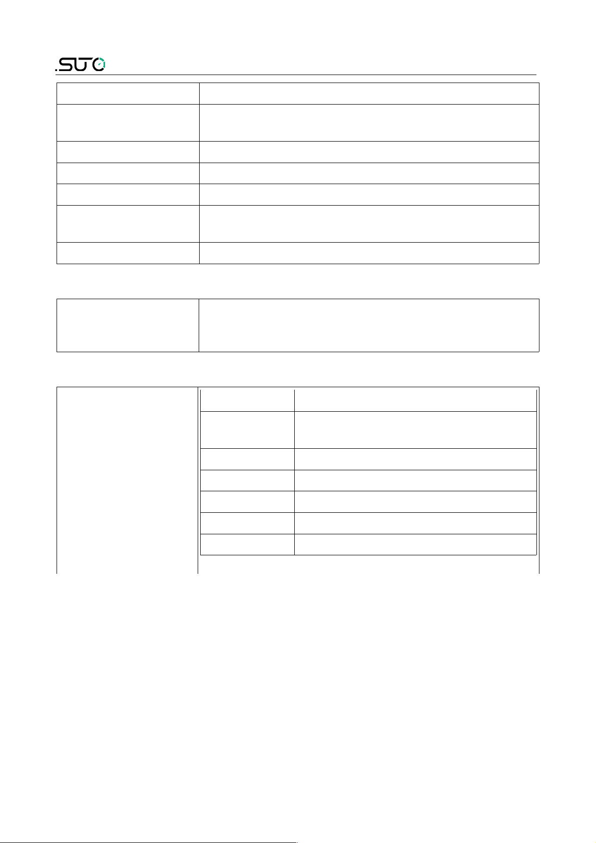
6.2 Connection with the optional isokinetic sampling device
The picture above shows the S 600 setup with the isokinetic sampling
device connected. Please connect the isokinetic sampling device using
the teflon hose delivered with the device. On the next page you can
find the detailed description of the sampling device. Also you can find
which outlets of the sampling device need to be connected to which
input at the S 600.
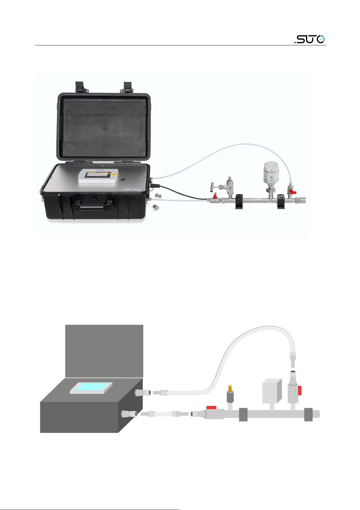
The following diagram helps you better understand the setup
connection.
S 600 17

6. Installation on site
1. Before connecting the S 600 to your compressed air, make sure
ball valve 2 and 4 are closed.
2. Close the needle valve 3.
3. The connection to your compressed air system is achieved through
the correct fitting (quick connector, teflon hose, etc.). Connect
your compressed air system to the inlet 1 using the correct
fitting.
4. Connect the outlet valve 2 to the inlet for dew point and oil
vapor measurement at the S 600 using a teflon hose.
5. Connect the isokinetic outlet 4 with the inlet for the particle
counting at the S 600.
6. Now open outlet valve 2 and 4 to start your measurementfollow
the instructions on the screen.
6.3 Connection without the isokinetic sampling device
Connect your compressed air system using two teflon hoses to the
corresponding inlets at the S 600. They are marked: Gas inlet Oil / Dew
point measurement and Gas inlet Particle measurement.
18 S 600

6. Installation on site
6.4 Electrical connections
The S 600 offers three types of electrical connections. The power
supply connector 1, the communication port for the isokinetic
sampling device 2 and an Ethernet port 3 to communicate with
network devices.
ATTENTION!
Only use the power supply which comes with the
S 600!
S 600 19

6. Installation on site
6.5 Compressed air connections (inlet and outlet)
The S 600 offers two compressed air inputs on the right side of the
housing. The inlets are shown on the picture above and are marked
respectively to their functions: Gas inlet Oil / Dew point measurement
and Gas inlet Particle measurement.
ATTENTION!
Permissible pressure!
Please observe the maximum permissible incoming
pressure. It must be in between 3 and 15 bar
overpressure. If the pressure exceeds this range, it
will damage the device. If the pressure is too low,
the volumetric flow will not be high enough which
will lead to wrong results.
20 S 600

6. Installation on site
In the picture below shows the left side of the housing where the gas
outlets can be found. The calibration outlets Gas outlet Dew point
measurement and Gas outlet Oil vapor measurement are used to
connect the internal sensors to references. These calibration outlets
must be opened all the time during compressed air is connected. Also
the other two outlets need to be opened before connected to the
compressed air.
Note!
All gas outlets of the
measurement device
must stay opened
during the complete
usage of the device.
S 600 21

7. Setup and configuration
7. Setup and configuration
The S 600 is configured ex-works and ready to work out of the box. The
S 600 provides a guided measurement procedure to guide you through
device setup for each measurement parameter. All these setup settings
are automatically saved into the device even after a power failure.
Note!
If you are facing problems setting up you device,
contact the manufacturer or your local dealer for
assistance.
8. Operation
After the S 600 gets
powered, the initialization
screen is displayed with an
active progress bar.
During initialization, the
device configures the
sensors and runs
initialization routines.
After the initialization is
completed, the date of the
last calibration is shown.
Click OK to proceed.
22 S 600

8. Operation
The value screen as shown
on the left appears.
Quick buttons or icon on the bottom bar are listed as follows:
• Graphic:To switch to the graphic view.
• Value: To switch to the value view.
• Menu: To access the operation sub-menus.
• The camera icon: To take a screenshot.
8.1 Value view
In this view, the S 600 shows all measured values in realtime.
To switch to the value
screen, click Value in the
bottom.
Note: During the first five minutes, the S 600 performs a purge process
to ensure any remaining particles in the system are blown out. During
this period, the counting numbers on the Particle pane appear green
and blink.
S 600 23

8. Operation
8.2 Graphic view
The graphic view is pre-configured in the factory, and you do not need
to change anything.
In case that you need to make changes, follow the instructions indicated
in the following figure.
8.3 Main menu
Access the main menu
by clicking Menu in the
bottom bar.
The screen with submenus is shown.
The main menu offers the access to the following sub-menus.
Guided
Measurement
To start the guided measurements, which lead you
through a complete measurement cycle. For more
24 S 600

8. Operation
information, see Chapter 9. Guided measurement.
Files To access the saved screenshots and the memory
usage as well.
Service info To show contact information for technical support.
System
settings
To perform general settings on date, time and
language and so on. To view information such as the
serial number.
Communication To perform field bus settings and configure
communication parameters
8.3.1 Files
The files menu shows all screenshots for you to view, export, and delete
them. You can also check the memory status.
8.3.2 Service Info
Shows contact information for technical support.
S 600 25

8. Operation
8.3.3 System Setting
You can perform general settings using this menu.
Password To set a password to protect the settings menu
from unauthorized access.
Back light To configure the brightness and the auto dimming
function of the screen.
Calibrate touch
screen
To calibrate the touch screen if it does not
respond to user inputs correctly or precisely, it
can be calibrated.
Language To select the interface language.
Date time To configure date and time.
26 S 600

8. Operation
Device info To view device information such as serial number.
System update To perform a system update.
Reset To restart the device (User settings will be
saved).
8.4 Icons in the status bar
USB memory stick is
connected. By pressing
the icon, the stick can
be disconnected.
System errors occur.
Press this icon to get
further information.
Calibration is overdue,
please. Contact the
manufacturer of your
local dealer.
The S 600 is connected
to a PC by the USB
cable.
Data logger status:
- STOP—Indicates that the data logger is not running.
- LOG—Indicates that the data logger is running.
9. Guided measurement
The S 600 provides a software-based guided measurement which takes
you through the complete measurement. This leads to a simplified
measurement process and prevents you from wrong measurements.
To start a guided measurement, do the following:
1. Click Menu > Guided measurement.
2. Select which type of measurement you want to perform.
S 600 27

9. Guided measurement
◦ Monitoring with programmed time out: It starts a
measurement with a user-programmed period of measurement
time. You can set the measurement time during the process of
measurement preparation. The system will then, after finishing
the programmed measurement duration, stop the measurement
automatically and save the data. This mode is ideally used for
audits where you must measure at several points. You can
program for each point a duration of e.g. 2 hours and then you
can compare the measurements.
◦ Monitoring with manual stop: It starts the measurement
without a programmed stop time. You can click it to start the
measurement and when you come back you can stop it. Then
you can decide if you want to save or delete the data. This can
be used to monitor changes in values.
3. Perform the guided measurement following the onscreen
instructions. For more information, see section 9.1 Steps for
guided measurement.
4. To view and manage the measurement files generated, click
Report Manager. For more information, see section 9.2 Reports
for guided measurements
28 S 600

9. Guided measurement
9.1 Steps for guided measurement
After you start a guided measurement, follow below steps to go through
the whole process.
1. An overview is given
about the selected
measurement types.
Click Yes to start.
2. The system asks if you
are using the isokinetic
sampling device, and
this will affect the
further steps and
instructions.
Select Yes if you have
the isokinetic sampling
device connected.
Otherwise, click No.
3. Input your data, which
will be then shown on
the report.
S 600 29

9. Guided measurement
4. Select your
compressed air class,
which will then select
the corresponding
alarms.
- CLASS 0: To
customize alarm
settings.
5. If you selected CLASS
0, enter the limit
values for each
measurement channel,
through which you
define different alarm
settings for the quality
management.
6. Enter how long the
measurement will take.
The longer it takes, the
more stabilized the
values will be and the
more exactly it will
represent the system
conditions.
30 S 600

9. Guided measurement
7. The system checks
whether the pressure is
in the valid range.
8. The system
performs the selfcalibration cycles and
cleans the internal
sensor components.
The following 3 steps only apply if you select Yes for the
isokinetic sampling device, otherwise skip the next 3 steps
1. The S 600 is now ready
for measurement.
Please read the
instructions shown on
the screen carefully.
Click Start.
S 600 31

9. Guided measurement
2. Follow the onscreen
instructions to proceed.
3. Perform Isokinetic
setup as instructed on
the screen.
Now the device is well set up and starts to measure data. The
remaining time is shown on the top left corner.
32 S 600

9. Guided measurement
During the measurement,
you can see the Data logger
status icon on the status bar
switched from STOP to LOG.
The remaining time is
displayed in the upper left
corner.
Please wait. The system will
stop the measurement
automatically.
When the measurement is
successfully completed, the
left screen appears. You can
choose discard or save the
measurement data.
9.2 Reports for guided measurements
After performing guided measurements, you can view and manage
measurement files through Guided Measurement > Report
Manager.
In the report screen:
• To view the
measurement results,
click on the file (not the
check box on the right).
A window appears
showing the PDF for your
preview.
• To copy, export , or
delete files, select the
file check boxes, and
then click the
corresponding button at
the bottom.
S 600 33

10. Optional accessories
10. Optional accessories
To purchase optional accessories, please contact the manufacturer or
your local dealer:
• Isokinetic sampling device, for particle sampling according to ISO
8573.
• Teflon hoses and sorts of adapters.
11. Maintenance
Use a moist fabric to clean the device. For the use in GMP areas, the
device must be disinfected through wipe disinfection. For more
information, please contact the manufacturer or your local dealer.
ATTENTION!
Please dry the device after cleaning using a clean
and dry fabric. Always take care, that the fabric for
cleaning is not to wet as water could get into the
device and lead to damage.
12. Disposal or waste
Electronic devices are recyclable material and do not
belong in the household waste.
The sensor, the accessories and its packing must be
disposed according to your local statutory requirements.
The dispose can also be carried by the manufacturer of the
product, for this please contact the manufacturer.
13. Warranty
SUTO provides a warranty for this product of 24 months covering the
material and workmanship under the stated operating conditions from
the date of delivery. Please report any findings immediately and within
the warranty time. If faults occur during the warranty time SUTO will
repair or replace the defective unit, without charge for labour and
material costs but there is a charge for other service such as transport
and packing costs.
Excluded from this warranty is:
• Damage caused by:
◦ Improper use and non-adherence to the instruction manual.
34 S 600

13. Warranty
◦ Use of unsuitable accessories.
◦ External influences (e.g. damage caused by vibration, damage
during transportation, excess heat or moisture).
• Sensor lifetime, which is determined by the operating hours
(6,000-hour sensor durability).
• Filter capacity, which is determined by the operating hours (8,640hour or 360-day lifetime).
The warranty is cancelled:
• If you open the measurement instrument without a direct request
written in this instruction manual.
• If repairs or modifications are undertaken by third parties or
unauthorized persons.
• If the serial number has been changed, damaged or removed.
• If the warranty sealing is removed or damaged.
Other claims, especially those for damage occurring outside the
instrument are not included unless responsibility is legally binding.
Warranty repairs do not extend the period of warranty.
ATTENTION!
Batteries have a reduced warranty time of 12
months.
S 600 35

SUTO iTEC GmbH SUTO iTEC (ASIA) Co., Ltd.
Werkstr. 2 Room 10, 6/F, Block B, Cambridge Plaza
79426 Buggingen 188 San Wan Road, Sheung Shui, N.T.
Germany Hong Kong
Tel: +49 (0) 7631 936889-0 Tel: +852 2328 9782
Fax: +49 (0) 7631 936889-19 Fax: +852 2671 3863
Email: sales@suto-itec.com Email: sales@suto-itec.asia
Website: http://www.suto-itec.com Website: http://www.suto-itec.com
All rights reserved © Modifications and errors reserved.
S600_im_en_2019-2
36 S 600
 Loading...