

Page 1

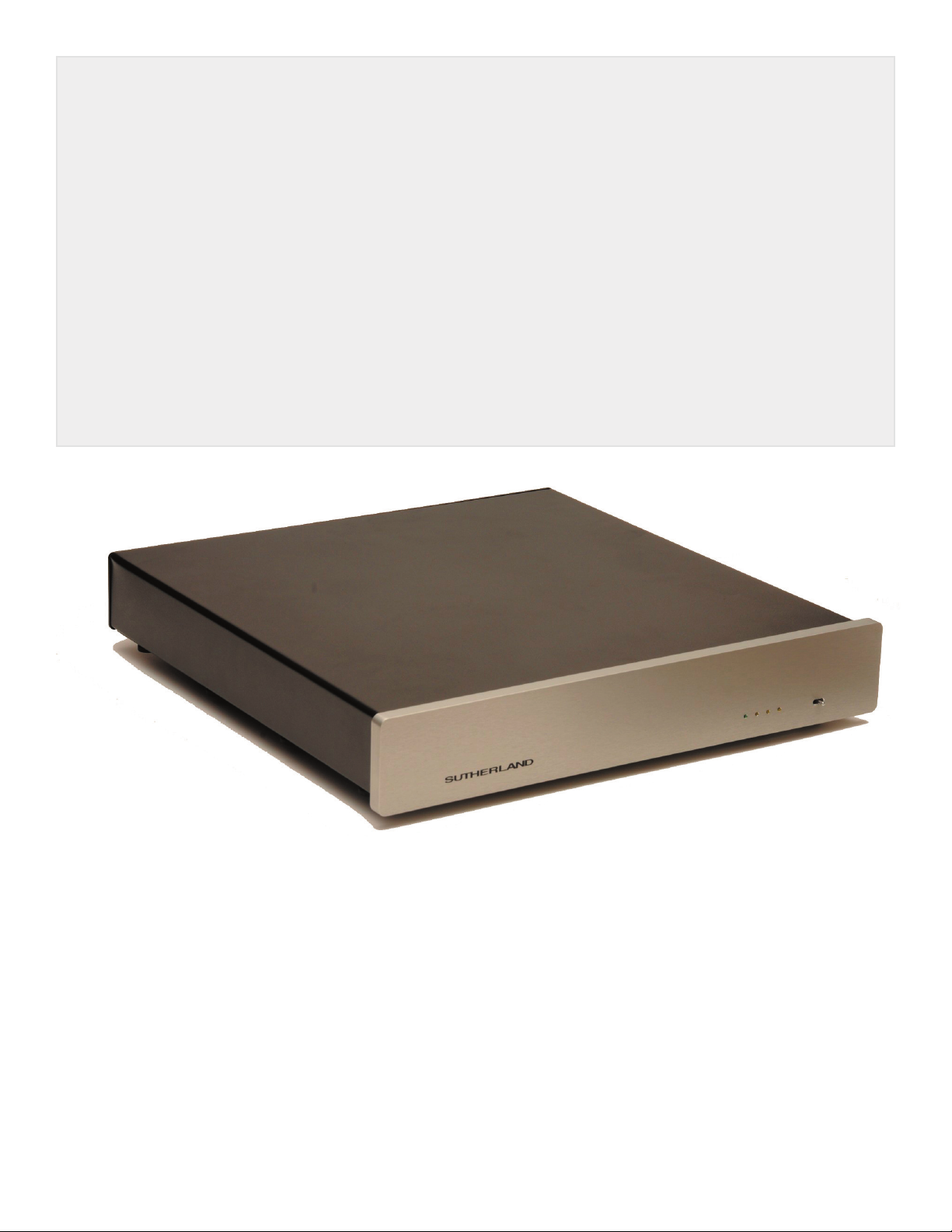
THE HUBBLE
-a phono preamplifi cation
instrument
by Sutherland Engineering
OWNER’S MANUAL
Page 2
A note from designer RON SUTHERLAND:
Thank you for purchasing the new Sutherland Hubble phono preamplifier, an instrument for discovery and exploration. With it, you can look deeply into the most subtle details of your treasured
music collection.
From any view point, the dove-tailed integration of aesthetics, performance, and technology will
affirm your choice to include it in your music system. It will earn your respect as a long-term, col
laborative teammate.
-
Even before you listen to the Hubble, you will recognize the correctness of its character. The sub
stantial size and weight are the first indications of its enduring build quality. But its svelte proportions, along with an uncluttered elegance, also speak of craftsmanship -- pride of ownership.
Happy Listening,
Ron
-
Table of Contents
Design Philosophy ........................................................... 3-5
Operation
- Gain and Loading ...................................................... 6
- Battery Installation and Requirements .................... 7
- Power Control ............................................................ 7
Specifications .................................................................. 8
Page 3

DESIGN PHILOSOPHY
A Blank Sheet of Paper...a perfect beginning
A new product is a new opportunity for perfection. With perfection as the goal, the Hubble started
with the only absolute, perfect beginning – a blank sheet of paper. Each element added to the perfect
start was meticulously scrutinized and evaluated before its inclusion. To avoid clutter in general, and
especially in the signal path, only essential ‘must have’ elements were allowed on the list.
Unlike conventional products, the design of the Hubble is not driven by the insatiable quest for a
longer list of more features. Absolutely nothing superfluous is permitted into the signal path. Simplicity of the signal path is the guiding principle. That rule is followed in an uncompromising, disciplined
way.
MUST HAVE A POWER SOURCE
The fundamental, bedrock requirement for revealing more detail is to create an environment well removed from back ground noise and interference. Any compromises in creating that isolated working
environment will leave details hidden in a foggy, cluttered back ground.
The Hubble phono preamplifier uses a self-contained battery pack to create the optimally quiet back
drop. It puts the greatest possible distance between the sensitive gain stages and the contaminating
influence of noisy AC power lines. Within that technically correct environment, audiophile circuitry con
veys a more involving, more focused experience.
The Hubble uses a power pack of 16 alkaline ‘D’ cell batteries. They have a very long life, are read
ily available anywhere in the world and are inexpensive to replace. They also completely remove the
Hubble from the AC power line and avoid any possibility of power line ‘ground loops’.
In addition to isolation from the AC power line, the power source must be very robust in its ability to pro
vide current to the amplifier stages. Current draw can vary with the musical signal. The power source
must remain solidly unaffected by those changing demands. Batteries alone do not satisfy that requirement. They are too far from the amplifier circuits and their internal impedance cannot be depended
on. Instead, they are used to keep banks of storage capacitors charged. Each mono preamplifier
board has it own bank of sixteen 1200 microfarad capacitors. The capacitors were selected for their
low equivalent-series-resistance at all frequencies. Putting sixteen capacitors in parallel reduces the
already low E.S.R. by an additional factor of 16. They are conservatively rated for long life operation at
temperatures up to 105 C. Each channel thus has it own 19,200 microfarads of capacitance available
for a rock-solid power source – located very near the actual amplifier circuitry.
-
-
-
MUST HAVE STEREO SEPARATION
A sense of space and dimensionality is conveyed by the difference in the left and right channel information. To preserve those auditory clues, each channel must be isolated from the other and not spill over.
That is why ‘dual mono’ is such a popular marketing term.
Dual mono implies that each channel of a stereo signal goes thru an identical signal path. Identical is
Page 4

DESIGN PHILOSOPHY
a ‘good’ thing. Each channel will be affected in the same way, arriving in the listening room with the
relative difference in channel information preserved. Thus, all the stereo information, ambience and
spatial clues are maintained.
But some designs are more ‘dual-mono’ than others. There is an opportunity to pull away from the ordi
nary by paying meticulous attention to construction and layout details. A look at ordinary layouts makes
it very clear that each channel sees a very different arrangement of channel components. This is
typically done to conveniently group back panel connectors, gain switches and loading switches. Even
though the channels have an identical circuit, the layout difference introduces subtle unbalances.
The Hubble (stereo version) takes dual-mono to a higher level. Each channel is completely contained
on a separate and identical circuit board. The boards are exactly the same. Each signal sees exactly
the same circuitry AND the same physical layout of components. The only thing shared is the case,
power control board and batteries. Even though shared, they are shared in an identical way, with chan
nel sameness maintained. Each mono board has its own energy storage capacity of 19,200 microfarads.
The Hubble (mono version) is as mono as it gets. It is literally a mono phono preamplifier. It was con
ceived for the collector of mono recordings that wants to listen with a mono cartridge. A pair of them
would be the ultimate ‘dual-mono’ stereophonic phono preamplifier.
MUST HAVE CONFIGURATION OPTIONS
-
-
-
One gain/load configuration will be optimum for a given system. There must be a mechanism
for finding and installing that best choice.
The common way puts every conceivable option on the circuit board. Then only one of the
available options is selected using some sort of switch. That approach is conventional, con
venient and it works. Some products even have remote control to select configuration. On
the down side, the circuit board layout is compromised with the clutter of fitting in all option
components. Signal path must wander thru the selector switch and the pile of unused option
components. Sometimes the selector switch is of high quality. More often, it is a cheap DIP
rocker switch – the sort for setting digital signals. Not at all appropriate for passing the minute
analog voltages from a phono cartridge.
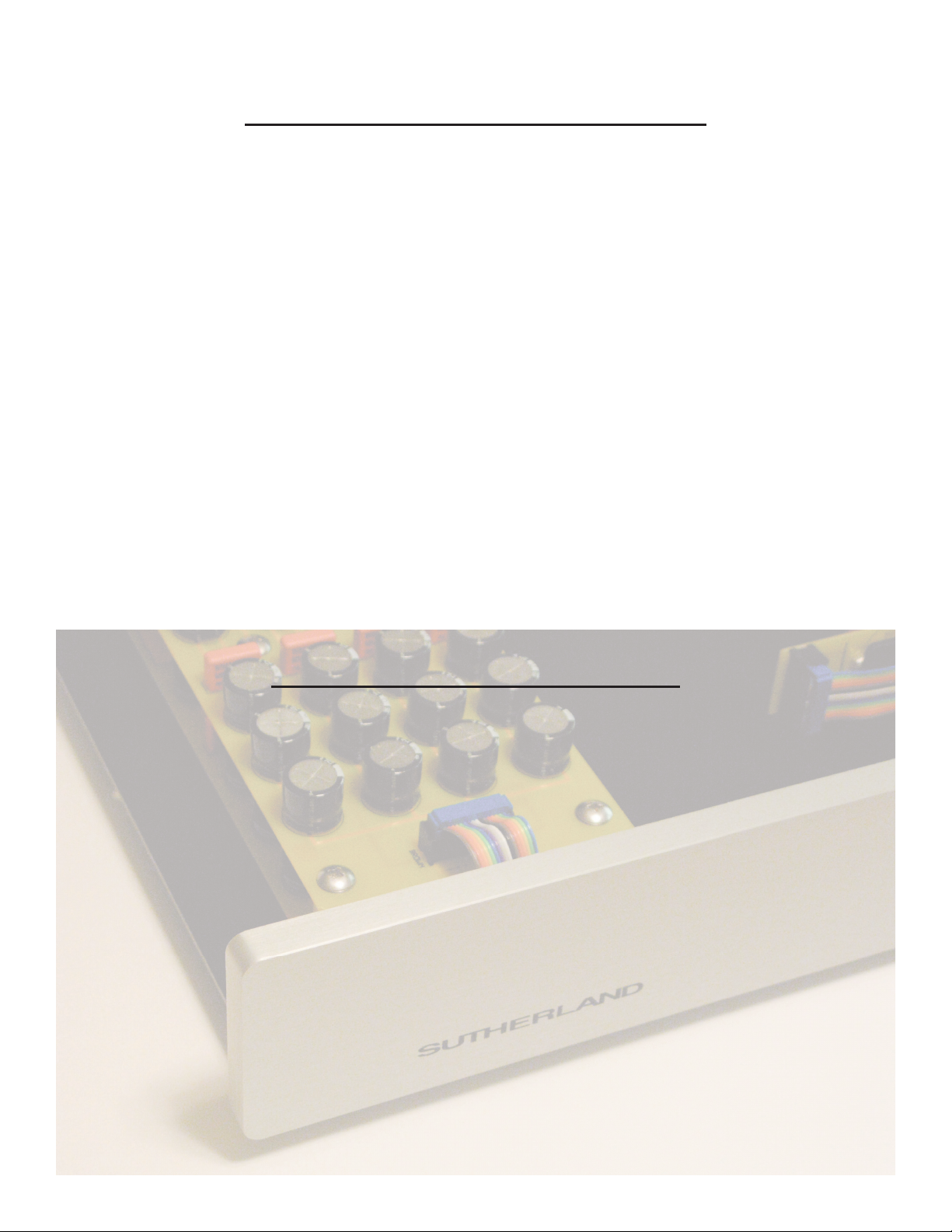
To keep the signal path tight and uncluttered, the Hubble uses plug in configuration boards.
Gold plated sockets for the configuration boards are located on the main circuit board very
close to the associated circuitry. Signal path length is kept short and direct. Only the one, op
timum value component is applied to the signal path. The Hubble comes with 4 gain options
and 7 cartridge loading values. In addition, blank plug-in boards are included for fine tuning
with custom values. You are not limited to standard values. Options are unlimited – but only
one is in the circuit.
-
-
Page 5
DESIGN PHILOSOPHY
MUST HAVE PHYSICAL CIRCUIT PLATFORM
Once a circuit topology is optimized for sound quality, it is critical that the surrounding physical
environment does not compromise that achievement. Anytime two conductors are at a different
voltage potential, there is an electric fi eld generated between them. Dielectrics within that fi eld
become involved in charge storage. If not carefully consider, that extra charge storage can time
smear details of a musical signal. Circuit board material is a dielectric. With normal doublesided construction, there are copper conductors on each side of the board. Unintentionally, a
new capacitor is introduced into the circuit, formed by top surface copper, bottom surface copper and the circuit board dielectric sandwiched between the two. Not the quality of capacitor to
have in a high-end signal path. Some manufactures make the situation even worse by going
to multi-layer boards. Instead of two layers of copper, there are four or more layers of copper.
Even worse than that, the dielectric between layers is much thinner and the undesired capacitive effect is inversely proportional to thickness.
The Hubble addresses the issue of circuit board dielectric in a novel – yet elegantly simple way.
All signal carrying conductors are on the top plane of the circuit board. There are no copper
conductors on the bottom plane of signal carrying regions. Thus there are no electric fi elds
generated between top and bottom layers. The circuit board dielectric is not exposed to electric
fi elds and there is no undesired storage in circuit board material. Very simple, very technically
correct, very effective and unique to the Hubble.
MUST HAVE HIGHEST QUALITY PARTS
FR-4 fi berglass circuit boards, Double-sided with plated thru holes
Dale/Vishay 1% metal fi lm resistors
Wima Polypropylene capacitors for power supply by passing
Custom wound, 1% polystyrene fi lm capacitors for equalization
12 gauge cold rolled steel base and battery compartment
baked epoxy powder coat fi nish
1/2 “ thick anodized aluminum panel
anodized in front panel artwork
gold plated, Tefl on insulated RCA connectors
gold plated confi guration headers and sockets
Page 6
OPERATION
Initial Set Up
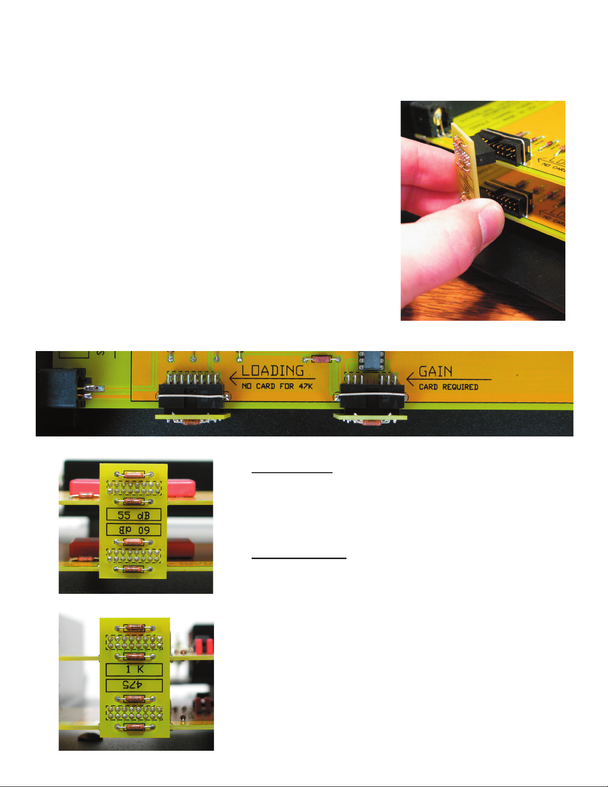
Release the top cover by removing the eight knurled screws on the
bottom plate. Audio boards are located on the left side of the
enclosure. On the left side of each circuit board you will find headers
for receiving the plug-in configuration boards. The Hubble is shipped
with a cartridge loading of 100 Ohms and a gain of 60 dB. If you wish
to change those values, locate the appropriately labeled plug-in board.
Each board carries two values and can be installed in one of two
orientations. Orient the board so the value you want has the writing
in the up position. Loading boards plug into headers toward the rear.
Gain setting boards plug into centrally located headers. Legends
printed on the circuit board clearly indicate position and function.
It is 100% OK and 100% safe to operate the Hubble with the top cover
removed. You may wish to leave the cover off when experimenting
with various configuration possibilities. There are no dangerous
voltages exposed with the cover removed.
Gain Options
45 dB or 50 dB
55 db or 60 dB
Loading Options
No card installed for 47.5 k Ohm
10 k Ohms or 4.75 k Ohms
1 k Ohms or 475 Ohms
200 Ohms or 100 Ohms
A blank plug-in board is furnished. Any desired loading
resistor and/or capacitor can be soldered to it. Install
identical values in both the upper and lower positions.
i.e. same values for each preamp channel.
Page 7
OPERATION
Installing Batteries
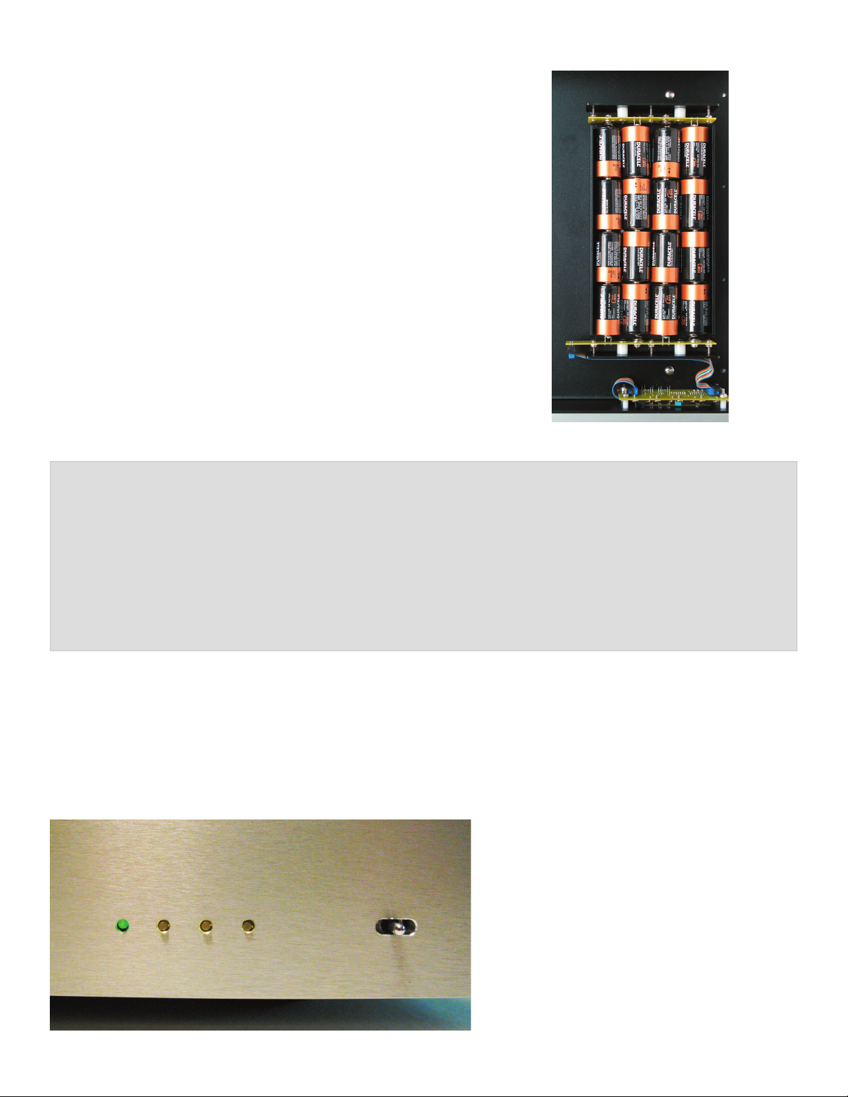
Power is furnished with sixteen alkaline ‘D’ cell batteries. With
normal operation, each set will last for approximately 1,000 hours
of ON time. Install the batteries end-to-end with the negative
terminals toward the large spring. Orient them as shown in the
photo. If they are installed incorrectly, no damage will be done.
Low Battery Indication
It is unlikely battery voltage will drop significantly within a year of
listening time. However, if batteries do need replacement, the
front panel power light will dim and then extinguish. When it is
fully
extinguished, battery voltage is down about 15%.
TO AVOID ANY POSSIBLITY OF DAMAGE FROM LEAKING
BATTERIES, IT IS A WARRANTY
REQUIREMENT THAT ALL
BATTERIES BE REPLACED ANNUALLY
YOUR WARRANTY DOES NOT COVER ANY DAMAGE
CAUSED BY BATTERY LEAKAGE
Power Control
Move the momentary toggle switch to the right to turn on power. The green light will then illuminate
to show power is ON (if batteries are low it will dim, or become fully extinguished). The Hubble will
remain ON for one hour and then automatically power down. If you wish to add more operating time,
each time the toggle switch is moved to the right, another hour will be added. Yellow lights indicate
how many additional hours have been added. After initial setting, they also indicate how many hours
of ON time remain. Additional hours can
be added at any time. The yellow lights
will blink when there are fewer than 10
minutes of ON time remaining.
Move the momentary toggle switch to
left to remove ON time. Each time it is
moved, one hour will be subtracted from
the remaining .
operating time.
Page 8

HUBBLE specifi cations
Gain settings
45 dB
50 dB
55 dB
60 dB
Cartridge Loading
100 ohms
200 ohms
475 ohms
1k ohms
4.75k ohms
47.5k ohms
Size
17” wide
3.25” high
16.75” deep
Weight
22 lbs. net
27 lbs. shipping
Power Requirements
16 Alkaline ‘D’ cells
Battery Life
1,000 hours
(actual power-on time)
(without batteries)
THE HUBBLE
www.sutherlandengineering.com
 Loading...