

Page 1

20/20
-a phono preamplification
instrument
by Sutherland Engineering
OWNER’S MANUAL
Page 2
A note from designer RON SUTHERLAND:
I like design challenges. That is how all new products begin. This time the challenge
was to offer an AC line powered phono preamp that would fit comfortably in with the
Sutherland series of battery powered phono preamps. An extremely low noise floor and
precise resolution was a must.
Not only was this an opportunity to creatively address AC power line isolation but to also
take dual mono to a new level.
And the other design challenges: do this with extremely high performance, extremely
high quality and extremely high value.
I sincerely thank my customers for giving me the opportunity to be their designer.
Ron Sutherland
Table of Contents
Design Philosophy .....................................................3-5
Gain and Loading ...................................................... 6
Specifications ............................................................7
Page 3
DESIGN PHILOSOPHY
Another path to the same destination.
It is a pleasure to announce a new phono preamplifier from Sutherland Engineering. It is derived
from the best elements of the PH3D and the Hubble. The signal path is almost the same as the
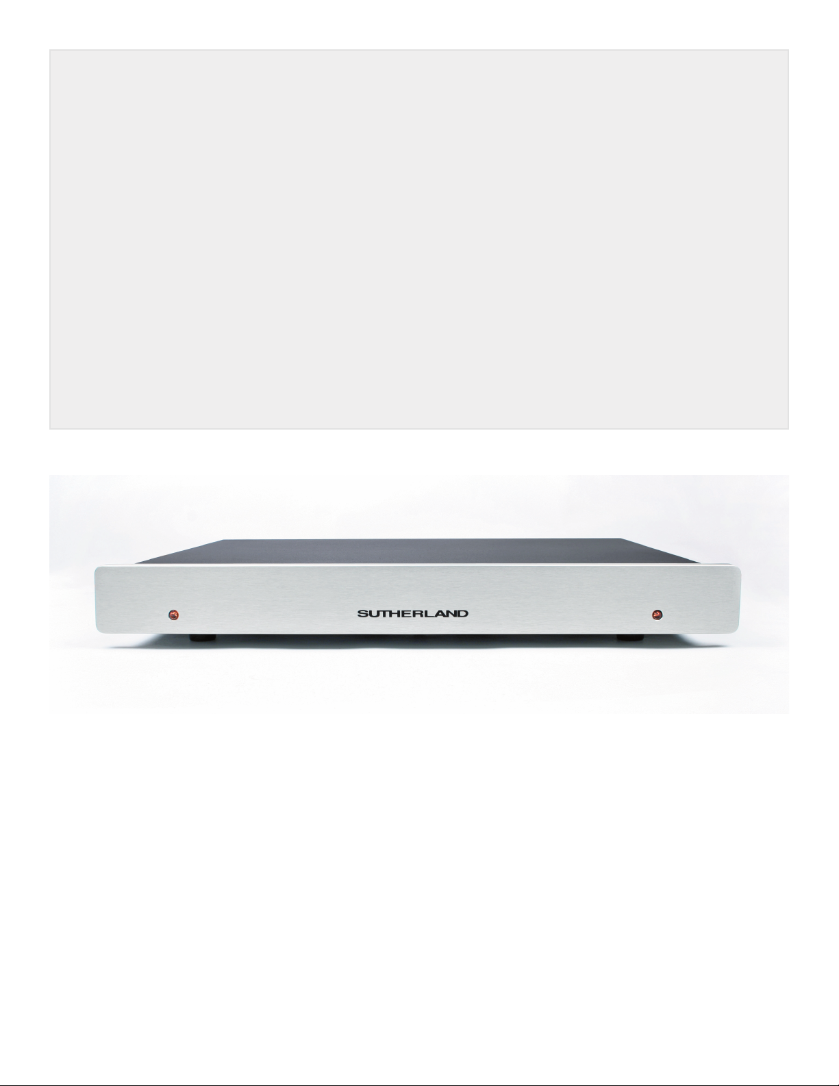
Hubble; the construction is as simple as the PH3D. It has an elegant esthetic of performance, value,
craftsmanship and minimalism.
That heritage, however, does not keep the 20/20 design from taking on its own unique character.
First. Everyone wants the advantages of AC power line isolation offered by battery operation. The
20/20 is for the person who wants those advantages, but does not want to mess with batteries. The
20/20 comes as close as possible to offering an equivalence of battery isolation from AC line power.
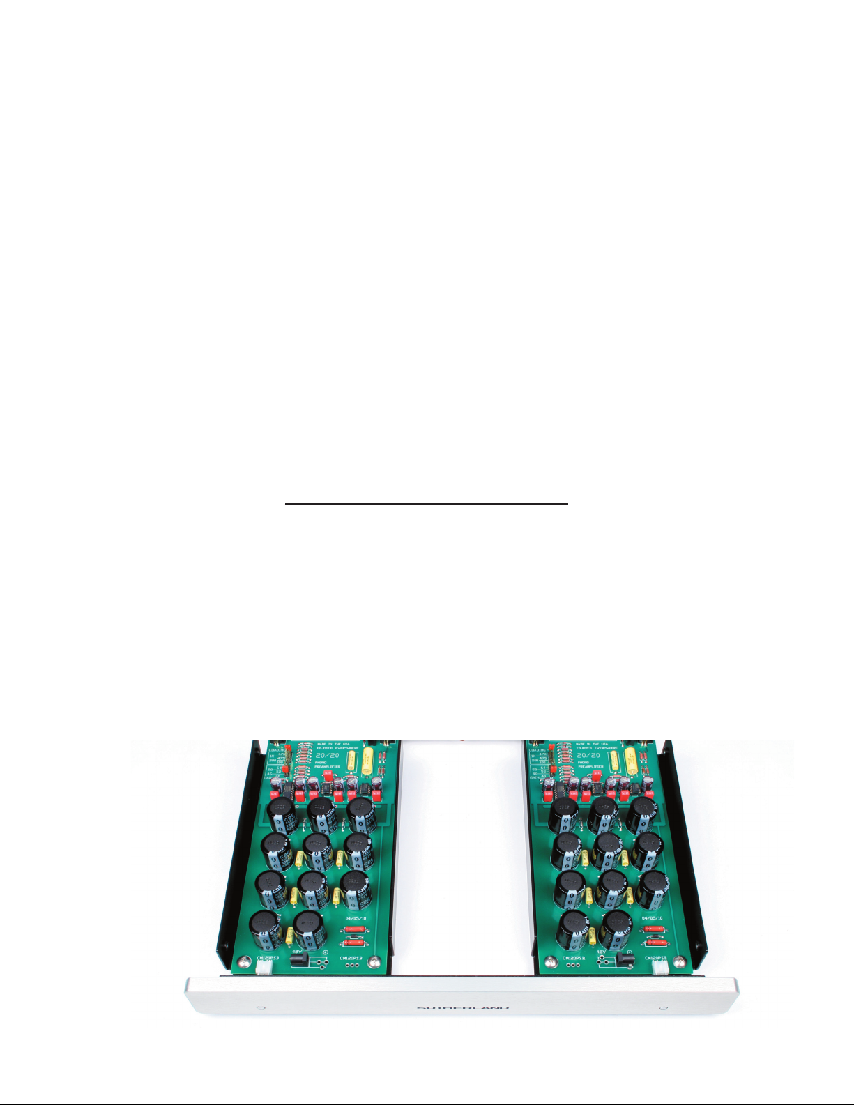
Second. Two-Mono (definition: bumping it up from dual-mono) construction. The 20/20 is literally two
identical mono phono preamplifiers. Each channel is on its own circuit board, has its own shielded
compartment, power indicator, its own AC power supply and its own power cord. It is the ultimate in
channel separation.
AC Power, the Sutherland Way
TWO-MONO
In the quest for the ultimate in stereo separation, the 20/20 goes beyond dual mono, offering instead
what I like to call “two-mono.” Many audiophiles prefer using mono-block amplification for the benefits
of eliminating crosstalk and other noise contaminants associated with shared power supplies. They
also prefer the benefit of each amp having its own resevoir of power, increasing dynamic capabilities,
and giving the amp a sense of ease. The exact advantage can be had in a phono-preamplifier, where
noise is the worst of enemies. The 20/20 may look like a conventional stereo phono stage, but take off
the cover. You will discover two identical mono phono circuit boards, sharing only the same front and
back panels. Power supplies, power cords , and all circuitry are separate. Even the power indicator
lights are independent.
Page 4

DESIGN PHILOSOPHY
POWER SUPPLIES
I don’t know of any audiophile who likes power supplies that even remotely resemble ‘walwarts’. The
20/20 uses not one, but two of the wallwarts more sophisticated relatives – politely called a regulated
tabletop power supply.
To understand this choice, let’s look at AC to DC power supply elements required for no-compromise
high-end performance:
1. Rectify the AC to DC
2. Filter that DC
3. Use that raw DC to power a regulating DC to DC switching inverter (this stage also provides
galvanic isolation between the AC power line and the DC load)
4. Provide additional levels of filtering to remove the high-frequency ripple from the switching
inverter.
5. Provide additional levels of noise isolation from the switching inverter to the load
6. Provide local voltage regulation right at the audio circuitry.
From an engineering viewpoint, items 1, 2 and 3 can be accomplished with a well chosen, off-the-shelf
table top power supply. It does those tasks well, reliably and at a very reasonable cost. The supplies
included with the 20/20 are rated at a MTF (Mean Time between Failure) of over 100,000 hours. They
are used at less than 10% of their rated capacity, so reliably should be even further increased. If one
were to fail, replacement is simple and inexpensive. In addition to that functionality, they are already
safety tested and approved for use all over the world. A great deal more time, effort and money could
be spent on custom circuitry – but to no performance advantage.
From an audiophile viewpoint, it is items 4, 5 and 6 that determine the quality of DC available for the
sensitive audio circuitry. That function is so important it takes up over 2/3 of each amplifier’s circuit
board area. Ten cascaded stages of passive RC filtering, provide an enormous distance from the pre
amp area to the incoming DC power connector. There are over 35,000 microfarads of capacitance
on each board. The electrical ‘distance’ is so great, when power is first applied, it takes over 10 seconds for the power to travel thru these ten sections of filtering and reach the preamp stage. Voltage
slowly ramps up until the zener diodes clamp it to the correct value. Until that voltage is reached, the
audio output is muted. It is this section of circuitry that provides the extreme isolation from AC power
line affects.
-
Page 5
DESIGN PHILOSOPHY
DC CONNECTOR LOCATION
Don’t be looking for power connections on the back panel. Instead, you will fi nd them located at the
front and under the cover. That is one of those form follows function decisions. The front of the circuit
board IS where the power enters the circuit, there fore that is where the connector went. On your car,
the gas cap is very near the gas tank. It is not located at the opposite end of the car.
Putting the entry point at the front permits power supply wires (low voltage DC) to be routed well away
from all the sensitive part of the circuit. Contrast that with the AC IEC power connector (high voltage
AC) conventionally located on the back panel very near the preamp circuitry and all the input/output
jacks.
Beautiful On the Inside
FR-4 fi berglass circuit boards, Double-sided with plated thru holes
Dale/Vishay 1% metal fi lm resistors
Wima Polypropylene capacitors for power supply by passing
Custom wound, 1% polystyrene fi lm capacitors for equalization
14 gauge cold rolled steel chassis
baked epoxy powder coat fi nish
1/2 “ thick anodized aluminum panel
front panel artwork anodized in
gold plated, Tefl on insulated RCA connectors
gold plated confi guration headers and sockets
output muted during power up and power down
Page 6
OPERATION
Initial Set Up
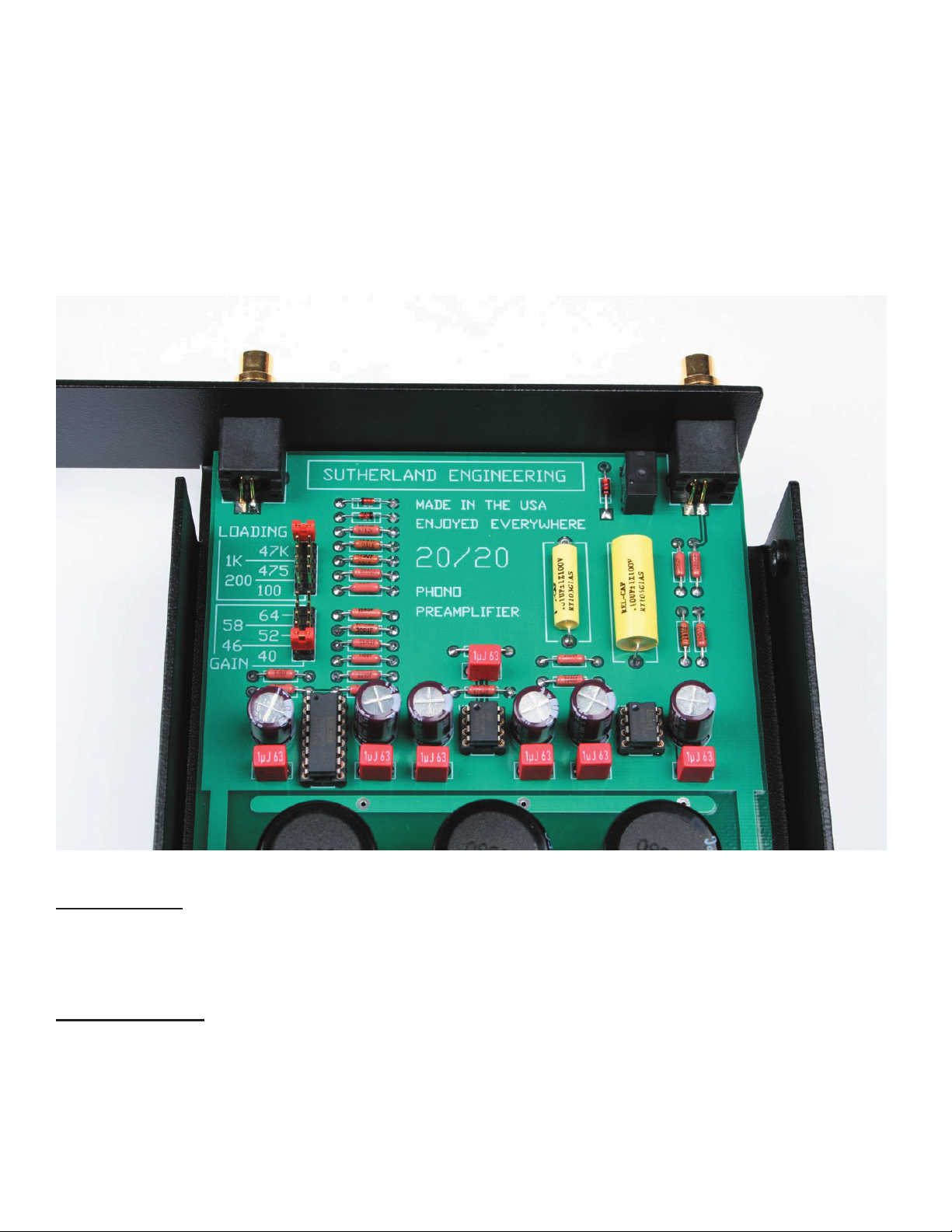
Release the top cover by removing the four knurled screws on the sides of the chassis. At the left rear of
each circuit board, you will find jumpers which are clearly labeled for changing cartridge loading and gain
settings. The 20/20 is shipped with a cartridge loading of 100 Ohms and a gain of 60 dB. If you wish to
change those values, simply move the jumper to the correct location for each channel. Make sure that you
match the loading and gain setting for each channel.
Gain Options
40 dB 46 dB 52 dB 58dB 64 dB
Loading Options
47.5 k Ohm 1 k Ohm 475 Ohm 200 Ohm 100 Ohm
Page 7

20/20 specifications
Gain settings
40 dB
46 dB
52 dB
58 dB
64 dB
Cartridge Loading
100 ohms
200 ohms
475 ohms
1k ohms
47k ohms
Size
17” wide
2 ¼ “ high
12” deep
-external power supply (each)
5” deep
1 ½” high
2” wide
Weight
11 lbs. net
19 lbs. shipping
Power Requirements
Power: 20 watts (10 watts per channel)
Operating Voltage: 100 to 240 volts
(universal, no adjustments)
20/20
www.sutherlandengineering.com
 Loading...