

Sussman ES 18, ES 24, ES 72, ES 30, ES 36 Installation, Operation And Maintenance Manual
...
Sussman Boilers: ES, SSB & HU
Installation, Operation and Maintenance Manual
TABLE OF CONTENTS
Dimensional Information
& Component Identification. . . . . . . . . . . . . . . . 2
Dimensional & Clearing Specifications . . . . . . . . 3
Wiring Diagrams . . . . . . . . . . . . . . . . . . . . . . . . 4-8
Installation
Piping . . . . . . . . . . . . . . . . . . . . . . . . . . . . . . . . 9
Wiring . . . . . . . . . . . . . . . . . . . . . . . . . . . . . 9-10
Pre-Operation Check. . . . . . . . . . . . . . . . . . . . . . 10
Pressure Controls, Operation & Testing . . . . . . . 11
Operation . . . . . . . . . . . . . . . . . . . . . . . . . . . . . . 11
Blowdown . . . . . . . . . . . . . . . . . . . . . . . . . . . . . 12
Maintenance . . . . . . . . . . . . . . . . . . . . . . . . . . . . 13
Optional Equipment . . . . . . . . . . . . . . . . . . . . . . 14
Auxilliary Low Water Cut Off . . . . . . . . . . . . . . . 14
Line Pressure Water Feed System
. . . . . . . . . . . . . 14
High Pressure Water Feed System . . . . . . . . . . . . 14
Condensate Return System . . . . . . . . . . . . . . . . . 14
Vacuum Breaker Systems . . . . . . . . . . . . . . . . . . 15
Automatic Blowdown System . . . . . . . . . . . . . . . 15
Blowdown Separators . . . . . . . . . . . . . . . . . . . . 15
Control Voltage Stepdown Transformer . . . . . . . . 15
Multistage Load Progressive Sequencers . . . . . . . 15
Condensate Return Systems. . . . . . . . . . . . . . . . 16
Blowdown Separator Tanks . . . . . . . . . . . . . . . . 17
Specification Charts . . . . . . . . . . . . . . . . . . . . . . 18
Sizing . . . . . . . . . . . . . . . . . . . . . . . . . . . . . . . . . 19
Gauge Glass Installation . . . . . . . . . . . . . . . . 20-21
Element Replacement . . . . . . . . . . . . . . . . . . . . . 22
Water Quality Information for Carbon
Steel Boilers . . . . . . . . . . . . . . . . . . . . . . . . . . 23
Warranty. . . . . . . . . . . . . . . . . . . . . . . . . . . . . . . 24
Products covered by this manual:
Max
Series KW Range Steam Rate* BHP Design Pres.
Work Pres.
______________________________________________________________________
ES, HU 12-180 36-542 lbs/hr 1.2-18.4 0-100 psig 85 psig
SSB 12-180 36-542 lbs/hr 1.2-18.4 0-100 psig 85 psig
*Steam Rate- Steam @ 212 F with 50 F feed water
SSB Boilers have all wetted metal parts Stainless Steel and are
required to be operated on distilled, de-ionized or RO type
water having a minimum specific resistivity of 1 Megohm-cm.
ES & HU Boilers are of Carbon Steel construction and are not
to be operated on distilled, deionized or RO type water.
A Division of Sussman-Automatic Corporation
43-20 34th Street, Long Island City, NY 11101 • (718) 937-4500
1-800-238-3535 • Fax: (718) 937-4676 • email: seb@sussmancorp.com
www.sussmanboilers.com
Made in USA
PUR 101137 07/03
states a hazard which may
cause serious injury or death if
precautions are not followed.
signals a situation where
minor injury or product damage
may occur if you do not follow instructions.
IMPORTANT NOTE:
This highlights information that is especially relevant to a problem-free installation.
IMPORTANT NOTE:
As you follow these instructions, you will notice warning and caution symbols. This blocked information is important for the safe and efficient installation and operation of
electric boilers. These are two types of potential hazards that may occur during this installation and operation:
!
CAUTION
!
WARNING
Model No. ______________________
Boiler Serial No. _________________
National Board No. ______________
Safety Valve Set Pressure________
PSIG
Power Circuit Voltage ____________
Control Circuit Voltage ___________
Amps _____ Phase _____ HZ ______
IMPORTANT:
This data file contains the National
Board Registration Certificate approving your boiler.
It must be kept near the boiler at all times.
Sussman Boilers
Installation, Operation & Maintenance Manual
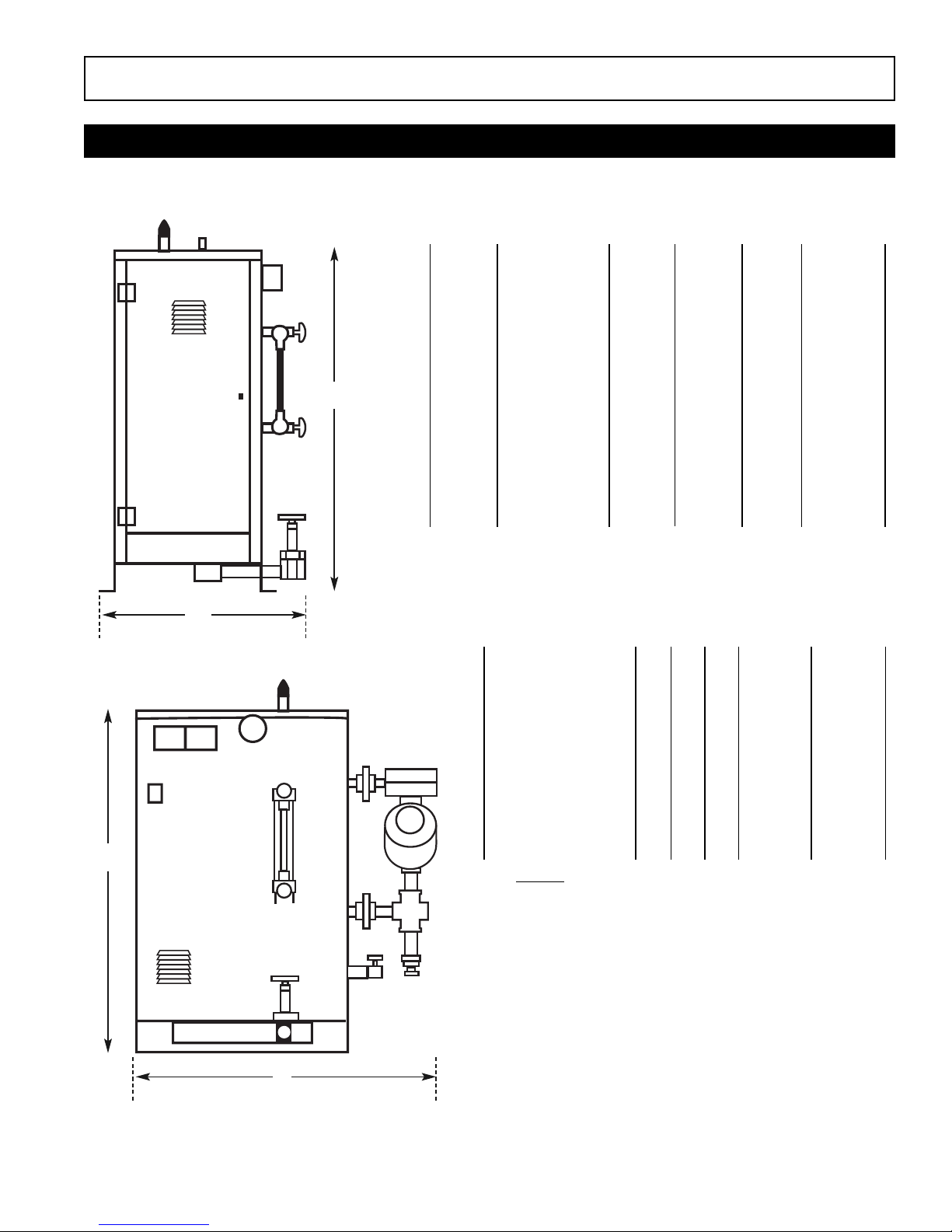
Dimensional Information & Component Identification
2
___________________________________________
WATER STEAM
MODEL H W L INLET OUTLET
___________________________________________
ES 12, 18; HU 40–55 36" 20" 28" 1/2” NPT 1/2”NPT
___________________________________________________
ES 24–72; HU 75–205 44" 23" 33" 1/2”NPT 1” NPT
___________________________________________________
ES 100; HU 310 59" 28" 34" 1/2”NPT 1 1/2”NPT
___________________________________________________
ES 135–180; HU 410–550 61" 30" 36" 1/2”NPT 2” NPT
___________________________________________________
SSB 12–18 36" 20" 28" 1/2”NPT 1/2”NPT
___________________________________________________
SSB 24–72 45" 27" 33" 1/2”NPT 1” NPT
___________________________________________________
SSB 80–100 59" 28" 34" 1/2”NPT 1 1/2”NPT
___________________________________________________
SSB 135–180 61" 30" 36" 1/2”NPT 2” NPT
___________________________________________
Allow minimum 21 inches clearance in front of door for servicing of heating
elements. Recommended clearance: 24 inches all around boiler for servicing.
H
H
L
W
Models: ES, HU, SSB
_______________________________________
SYMBOL ITEM ES12-18 ES24-72 ES100 ES135-180
_______________________________________
Height Overall Height 36" 44" 59" 61"
________________________________________________________________________
Length Overall Length 28" 33" 34" 38"
_________________________________________________________________________
Width Overall Width 20" 22" 26" 30"
_________________________________________________________________________
A Steam Outlet 6-1/4" 10" 8-1/4" 9"
_________________________________________________________________________
B Steam Outlet 10-1/4" 17" 17-1/4" 18-1/4"
_________________________________________________________________________
C M/M Drain Valve 5" 12" 17" 16-3/4"
_________________________________________________________________________
D M/M Drain Valve 6-1/2" 6" 6-1/4" 6-1/4"
_________________________________________________________________________
E Check Valve 14" 9" 17" 16-3/4"
_________________________________________________________________________
F PV Drain Valve 2-3/4" 2-1/4" 2-3/4" 2-3/4"
_________________________________________________________________________
G PV Drain Valve 6-1/4" 9-1/2" 7-3/4" 9-1/4"
_________________________________________________________________________
J Clearance 3-3/4" 3-1/2" 4" 4"
_________________________________________________________________________
K Check Valve 2-1/2" 2-3/4" 3" 3"
_________________________________________________________________________
M Door Width 8-3/4" 14" 12-3/4" 14-3/4"
_________________________________________________________________________
Allow 24 inches all around for servicing.
Sussman Boilers
Installation, Operation & Maintenance Manual
3
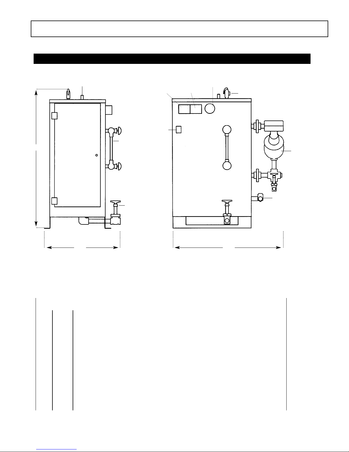
Dimensional & Clearance Specifications
Steam Outlet
High Limit
Pressure
Control
Operating
Pressure
Control
Pressure
Gauge
15 PSIG
Safety Valve
MM 150 Liquid
Level Control
(see note 3)
Water Feed Inlet
F
E
L
D
A
B
E
R
FrontLeft
Drain Valve
On/Off
Switch
Gauge Glass
Assembly
Height
Width Length
Side Elevation Front Elevation
Allow 24" all around for servicing.
__________________________________________________
Clearance from combustible surfaces
__________________________________________________
A
1" Clearance above top of boiler
_________________________________________________________________________
B
A Clearance from Front of boiler. Prefix "C" to numeral indicates acceptability for
closet or alcove installations; prefix acceptability for alcove installations but not
for closet installations.
_________________________________________________________________________
D
1" Clearance from back of boiler.
_________________________________________________________________________
EL
1" Clearance from left side of boiler.
_________________________________________________________________________
ER
16" Clearance from right side of boiler.
_________________________________________________________________________
F
C Indicates type of flooring: "NC" for non-combustible; "C" for combustible.
Numeral indicates minimum clearance below suspended units to combustible floor.
_________________________________________________________________________
G-
Total minimum free area in square inches of close ventilating openings.
_________________________________________________________________________
Sussman Boilers
Installation, Operation & Maintenance Manual
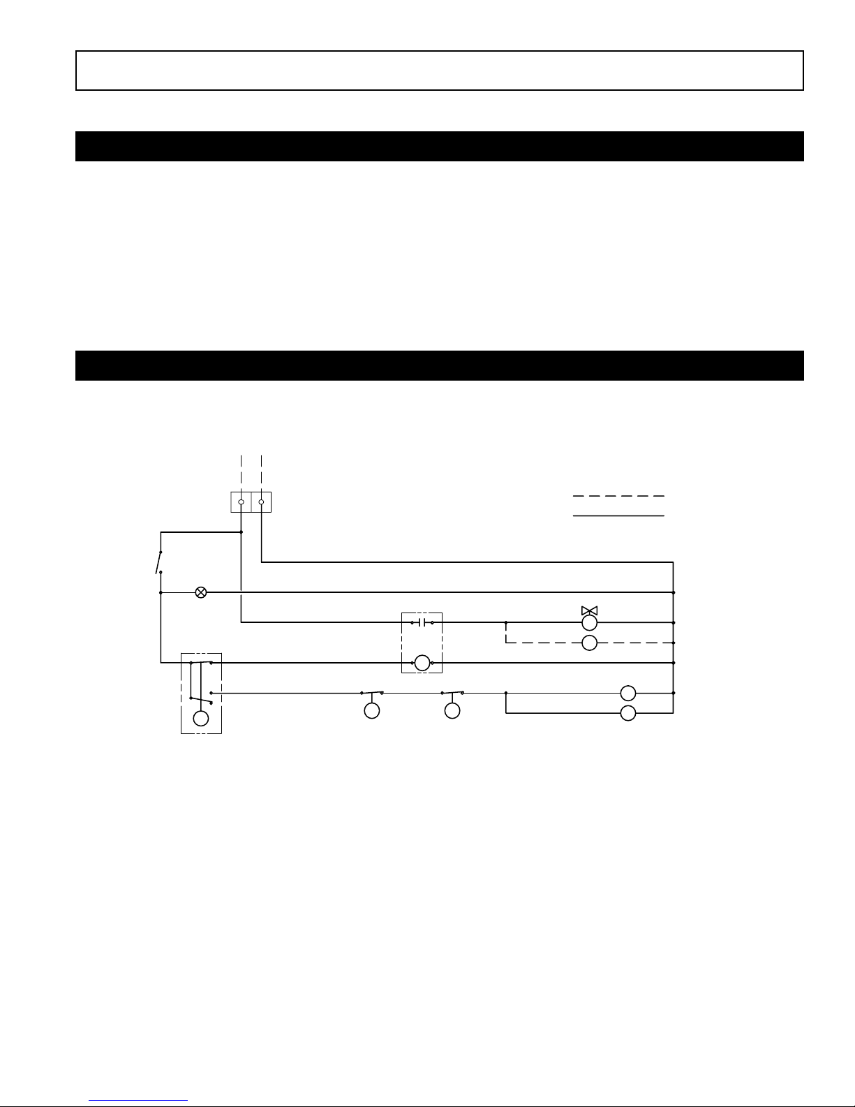
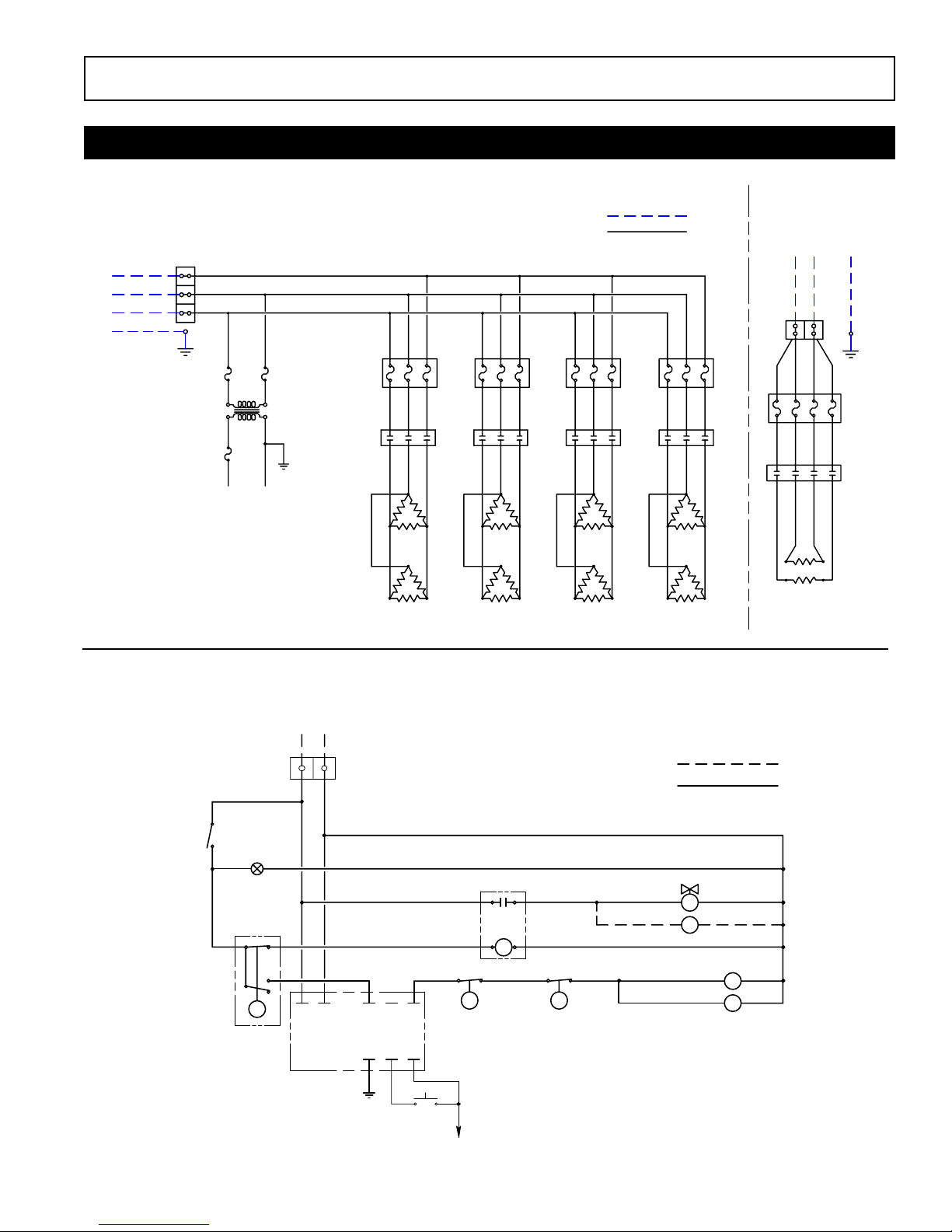
Typical Wiring Diagrams:
Wiring Diagram Control Circuit
4
a.
Three phase power circuit with separate 120Volt control circuit. (With singe phase power circuit insert.)
b.
Three phase power circuit with step down transformer.
c.
Detailed ES81017/81017MR auxiliary low water cut off wiring.
d.
Detailed SSB auxiliary low water cut off wiring.
e.
ES81600 Auto blowdown wiring diagram.
f.
Detailed sequencer package wiring diagram.
ES and SSB Electric Boilers
120V 1PH
INPUT
ON-OFF
SWITCH
PILOT
LIGHT
L
LIQUID
LEVEL
CONTROL
L
L1 L2
N
CONTROL
TERMINAL
BLOCK
P1
HIGH LIMIT
PRESSURE
CONTROL
R
RELAY
P2
OPERATING
PRESSURE
CONTROL
FIELD WIRING
FACTORY WIRING
SOLENOID VALVE
S
PUMP MOTOR
M
CONTACTORS
C1
C2
Sussman Boilers
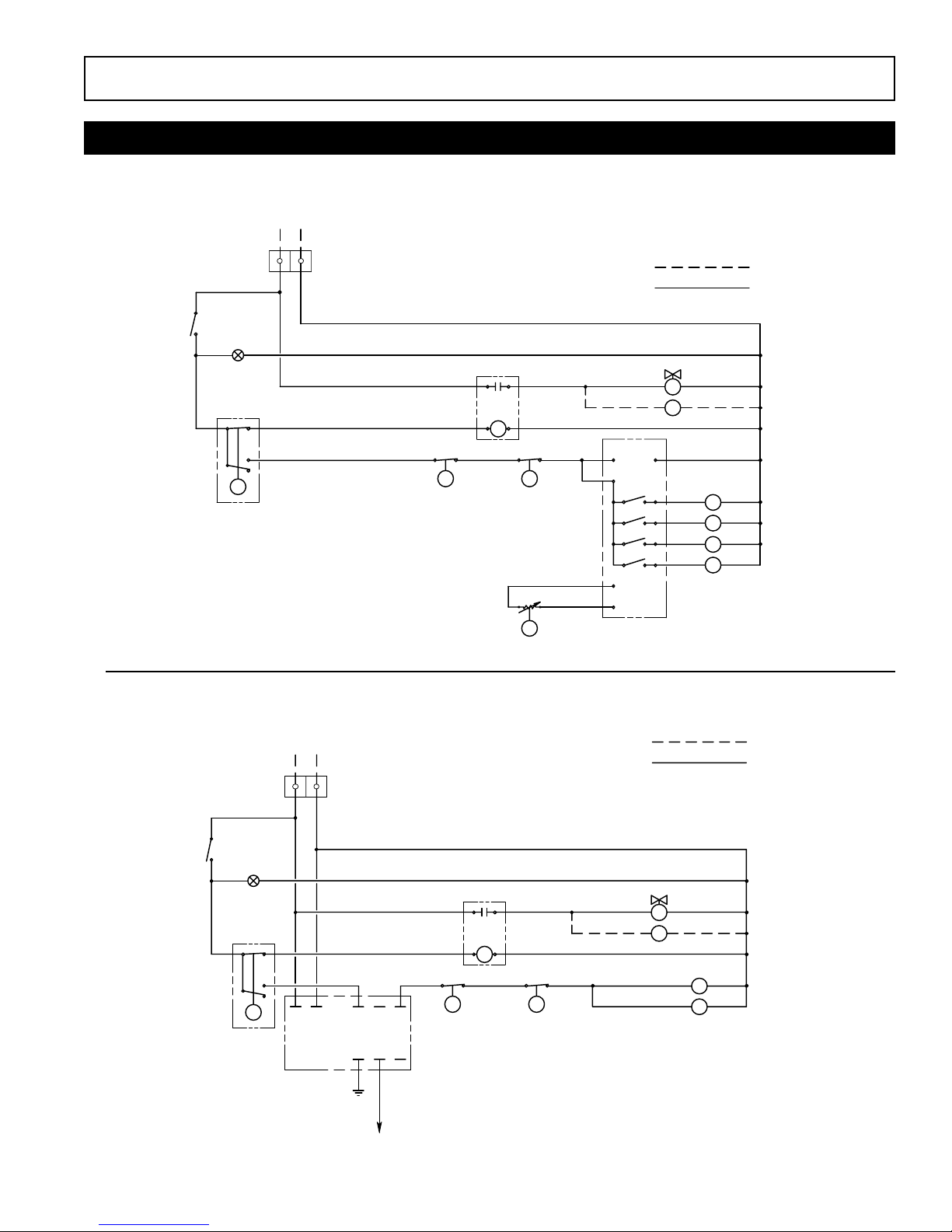
Installation, Operation & Maintenance Manual
Wiring Diagram Control Circuit
5
ES Electric Boilers with Manual Reset- Auxiliary Low Water Cutoff
ES and SSB Electric Boilers
THREE PHASE
MAIN POWER
SUPPLY
L1
L2
L3
G
TRANSFORMER
NOTES:
1. Power Terminal Block only on boilers with two or more contactors
2. Power Fuses only on boilers rated 20 amperes and larger.
3. See Parts List for contactor and heating element information.
TB 1
(optional)
TO CONTROL
TERMINAL POWER BLOCK
(see note 1)
PILOT
LIGHT
480V
T1
120V
CIRCUIT
POWER FUSES
(see Note 2)
CONTACTORS C1 C2 C3 C4
HEATING
ELEMENTS
FIELD WIRING
FACTORY WIRING
FB1 FB2 FB3 FB4
H1 H3 H5 H7
H2 H4 H6 H8
SINGLE PHASE
MAIN POWER SUPPLY
L1 L2 G
TB
FB
C
H
120V 1PH
INPUT
N
L
ON-OFF
SWITCH
PILOT
LIGHT
L
LIQUID
LEVEL
CONTROL
L1
L2
AUX LWCO
PC BOARD
MANUAL RESET
CONTROL
TERMINAL
BLOCK
COM
C
RELAY
NC
NO
HIGH LIMIT
PRESSURE
HI
CONTROL
LO
TO
PROBE
R
P1
P2
OPERATING
PRESSURE
CONTROL
FIELD WIRING
FACTORY WIRING
SOLENOID VALVE
S
PUMP MOTOR
M
CONTACTORS
C1
C2
Sussman Boilers
Installation, Operation & Maintenance Manual
Wiring Diagram Control Circuit
6
ES Electric Boilers with Manual Reset- Auxiliary Low Water Cutoff
ES Electric Boiler with Auxiliary Low Water Cutoff
120V 1PH
INPUT
L N
CONTROL
TERMINAL
BLOCK
FIELD WIRING
FACTORY WIRING
ON-OFF
SWITCH
CONTROL
PILOT
LIGHT
L
LIQUID
LEVEL
L1 L2
RELAY
P1
HIGH LIMIT
PRESSURE
CONTROL
R
P2
OPERATING
PRESSURE
CONTROL
PROPORTIONING
PRESSURE CONTROL
P3
120V COM
M
135 OHM
COM
SEQUENCER
120V 1PH
INPUT
LN
CONTROL
TERMINAL
BLOCK
FIELD WIRING
FACTORY WIRING
S
M
1
2
3
4
SOLENOID VALVE
PUMP MOTOR
C1
C2
C3
C4
CONTACTORS
ON-OFF
SWITCH
PILOT
LIGHT
L
L1 L2 COM NC NO
LIQUID
LEVEL
CONTROL
AUX LWCO
PC BOARD
C HI LO
TO PROBE
RELAY
P1
HIGH LIMIT
PRESSURE
CONTROL
SOLENOID VALVE
S
PUMP MOTOR
M
R
C1
P2
OPERATING
PRESSURE
CONTROL
C2
CONTACTORS

Sussman Boilers
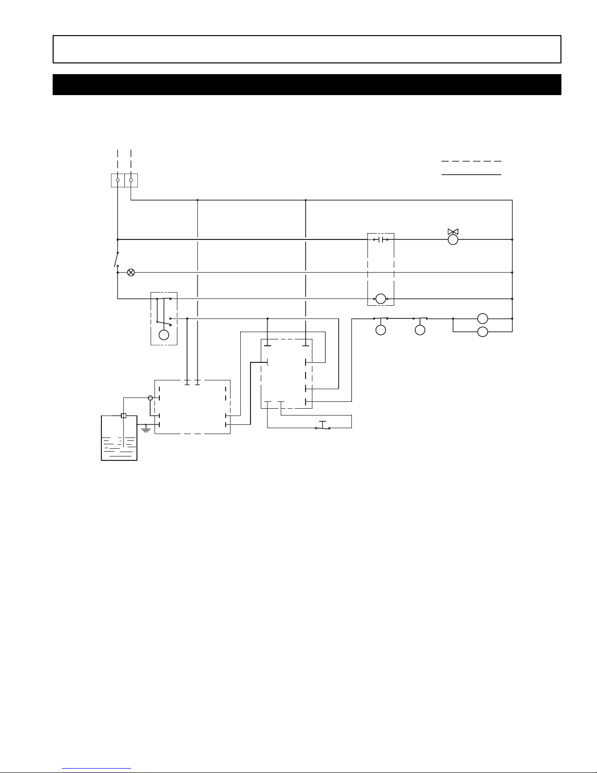
Installation, Operation & Maintenance Manual
Wiring Diagram Control Circuit
7
ES and SSB Electric Boilers with Automatic Blowdown System
ES and SSB Electric Boilers with Automatic Blowdown System
ON-OFF
SWITCH
PILOT
LIGHT
L
LIQUID
LEVEL
CONTROL
120V 1PH
INPUT
L N
CONTROL
TERMINAL
BLOCK
T
7-DAY 24-HR
TIMER
ES81600
AUTOMATIC
BLOWDOWN SYSTEM
P1
HIGH LIMIT
PRESSURE
CONTROL
PROPORTIONING
PRESSURE CONTROL
R
RELAY
OPERATING
PRESSURE
CONTROL
TIME DELAY RELAY
P2
FIELD WIRING
FACTORY WIRING
D
PILOT LIGHT
2
OPEN
CLOSE
3
MOTORIZED
BLOWDOWN
VALVE
M
1
SOLENOID VALVE
S
PUMP MOTOR
CONTACTORS
C1
C2
ON-OFF
SWITCH
PROBE
120V 1PH
INPUT
Hot Leg
PILOT
LIGHT
Neutral
CONTROL
TERMINAL
BLOCK
LIQUID
LEVEL
CONTROL
L
L1 L2
LO
GUARD
GROUND
AUX LWCO BOARD
LWCO
LWCO
RELAY
R
P1
HIGH LIMIT
PRESSURE
CONTROL
FIELD WIRING
FACTORY WIRING
SOLENOID VALVE
P2
AUTOMATIC
PRESSURE
CONTROL
S
CONTACTORS
C1
C2
BOILER SHELL
Sussman Boilers
Installation, Operation & Maintenance Manual
Wiring Diagram Control Circuit
8
SSB Electric Boilers with Manual Reset, Auxiliary Low Water Cutoff
120V 1PH
INPUT
ON-OFF
SWITCH
PROBE
L N
PILOT
LIGHT
CONTROL
TERMINAL
BLOCK
LIQUID
CONTROL
L
LEVEL
LO
GUARD
GROUND
AUX LWCO BOARD
L1 L2
LWCO
LWCO
L1 L2
LLCO
NC
COM
RESET
NO
G
MANUAL RESET
RELAY
HIGH LIMIT
PRESSURE
CONTROL
R
P1
FIELD WIRING
FACTORY WIRING
P2
AUTOMATIC
PRESSURE
CONTROL
S
SOLENOID VALVE
C1
C4
CONTACTORS
BOILER SHELL
 Loading...