

Sussman ES series, HU series, ES 12, ES 18, ES 24 Installation, Operation And Maintenance Manual
...Page 1

ES & HU Installation, Operation
and Maintenance Manual
Model No. _____________________________________
Boiler Serial No. _______________________________
National Board No. ___________________________
Safety Valve Set Pressure _______________ PSIG
Power Circuit Voltage _______________________
Control Circuit Voltage ______________________
Amps __________ Phase _________ HZ __________
Steam Outlet Valve Size _____________ NPT
IMPORTANT:
This data file contains the National
Board Registration Certificate approving your boiler.
It must be kept near the boiler at all times.
Products covered by this manual:
_________________________________________________________________________________
KW Max Design Work
Series Range Steam Rate* BHP Pressure Pressure
_________________________________________________________________________________
ES, HU 12-180 36-542 lbs/hr 1.2-18.4 0-100 psig 85 psig
_________________________________________________________________________________
*Steam Rate: Steam at 212˚ F with 50˚ F feed water
ES and HU boilers are of Carbon Steel construction.
See page 23 for Water Quality Information.
TABLE OF CONTENTS
Dimensional Information and
Component Identification . . . . . . . . . . . . . . . . . 2
Dimensional & Clearing Specifications. . . . . . . . . 3
Wiring Diagrams . . . . . . . . . . . . . . . . . . . . . . . . . 4-7
Installation
Piping. . . . . . . . . . . . . . . . . . . . . . . . . . . . . . . . . . 8
Wiring . . . . . . . . . . . . . . . . . . . . . . . . . . . . . . . . . 9
Pre-Operation Check . . . . . . . . . . . . . . . . . . . . . . . 10
Pressure Controls, Operation & Testing . . . . . . . 10
Operation. . . . . . . . . . . . . . . . . . . . . . . . . . . . . . . . 11
Blowdown . . . . . . . . . . . . . . . . . . . . . . . . . . . . . . . 11
Digital Timer Operation Instructions. . . . . . . . . . 12
Timing Switch . . . . . . . . . . . . . . . . . . . . . . . . . . . . 13
Maintenance . . . . . . . . . . . . . . . . . . . . . . . . . . . . . 13
Standard Equipment
Auxiliary Low Water Cut Off . . . . . . . . . . . . . . . . 14
Line Pressure Water Feed System . . . . . . . . . . . . . 14
Optional Equipment
High Pressure Water Feed System. . . . . . . . . . . . . 14
Condensate Return System. . . . . . . . . . . . . . . . . . 14
Vacuum Breaker Systems . . . . . . . . . . . . . . . . . . . 15
Automatic Blowdown System. . . . . . . . . . . . . . . . 15
Control Voltage Stepdown Transformer . . . . . . . . 15
Blowdown Separators . . . . . . . . . . . . . . . . . . . . . 15
Multistage Load Progressive Sequencers . . . . . . . . 15
Condensate Return Systems . . . . . . . . . . . . . . . . 16
Blowdown Separator Tanks . . . . . . . . . . . . . . . . . 17
Specification Charts . . . . . . . . . . . . . . . . . . . . . . . 18
Sizing . . . . . . . . . . . . . . . . . . . . . . . . . . . . . . . . . . . 19
Gauge Glass Installation . . . . . . . . . . . . . . . . . 20-21
Element Replacement . . . . . . . . . . . . . . . . . . . . . . 22
Water Quality Information
for Carbon Steel Boilers . . . . . . . . . . . . . . . . . . 23
IMPORTANT NOTE:
As you follow these instructions, you will notice warning and caution symbols. This blocked information is important for the safe and efficient
installation and operation of electric boilers. These are two types of potential hazards that may occur during this installation and operation:
WARN I N G
!
may cause serious injury or death if precautions
are not followed.
states a hazard which
CAUTIO N
!
minor injury or product damage may occur if you
do not follow instructions.
A Division of Sussman-Automatic Corporation
43-20 34th Street, Long Island City, NY 11101 • (718) 937-4500
1-800-238-3535 • Fax: (718) 937-4676 • email: [email protected]
www.sussmanboilers.com
signals a situation where
IMPORTANT NOTE:
This highlights information that is especially relevant to a problem-free installation.
M A D E I N U S A
PUR 101137 4.13
Page 2
Installation, Operation & Maintenance Manual
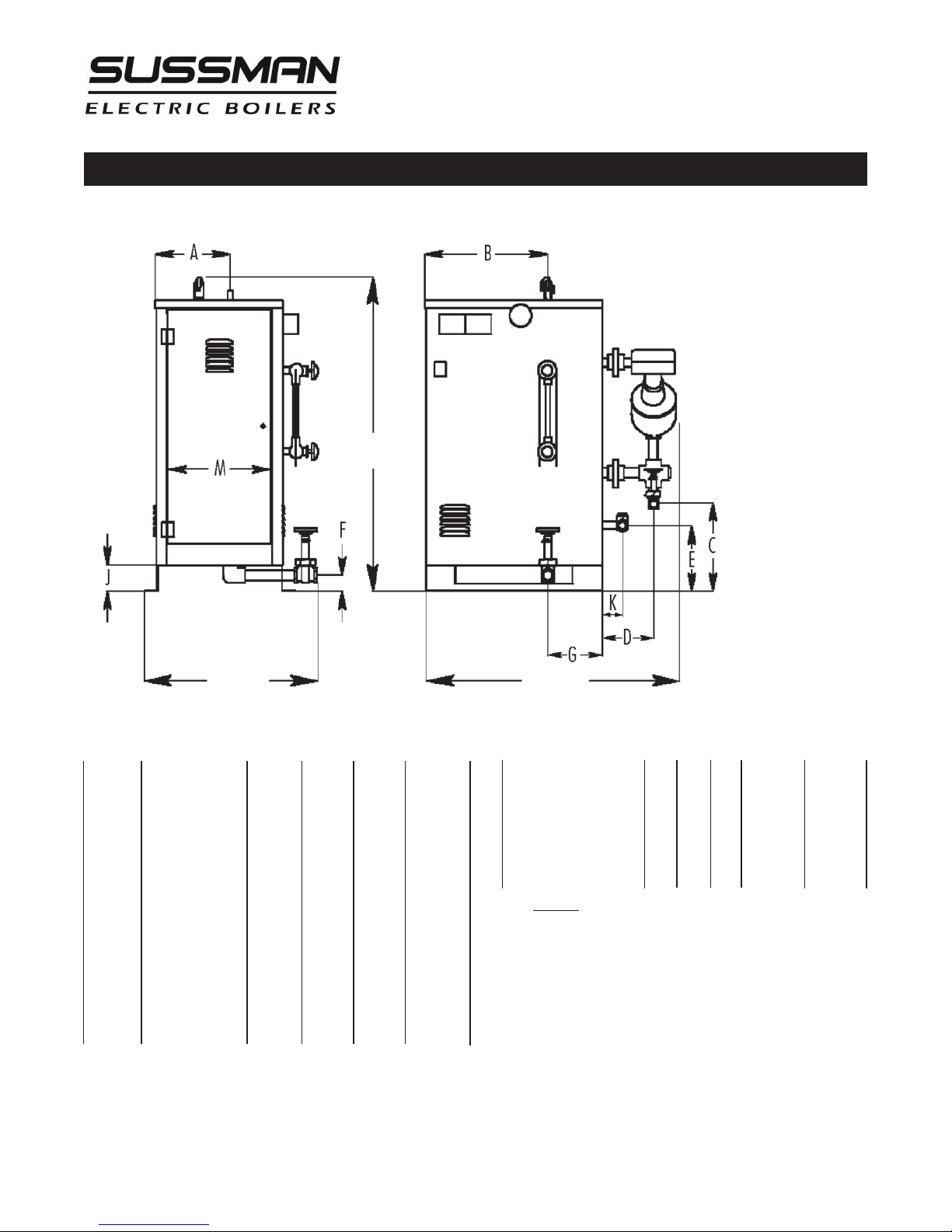
Dimensional Information & Component Identification
Models: ES, HU
Height
Width
_________________________________
SYMBOL ITEM ES12-18 ES24-72 ES100 ES135-180
___________________________________
Height Overall Height 36" 44" 59" 61"
__________________________________________________________________
Length Overall Length 28" 33" 34" 38"
__________________________________________________________________
Width Overall Width 20" 22" 26" 30"
__________________________________________________________________
A Steam Outlet 6-1/4" 10" 8-1/4" 9"
__________________________________________________________________
B Steam Outlet 10-1/4" 17" 17-1/4" 18-1/4"
__________________________________________________________________
C M/M Drain Valve 5" 12" 17" 16-3/4"
__________________________________________________________________
D M/M Drain Valve 6-1/2" 6" 6-1/4" 6-1/4"
__________________________________________________________________
E Check Valve 14" 9" 17" 16-3/4"
__________________________________________________________________
F PV Drain Valve 2-3/4" 2-1/4" 2-3/4" 2-3/4"
__________________________________________________________________
G PV Drain Valve 6-1/4" 9-1/2" 7-3/4" 9-1/4"
__________________________________________________________________
J Clearance 3-3/4" 3-1/2" 4" 4"
__________________________________________________________________
K Check Valve 2-1/2" 2-3/4" 3" 3"
__________________________________________________________________
M Door Width 8-3/4" 14" 12-3/4" 14-3/4"
__________________________________________________________________
Allow 24 inches all around for servicing.
Length
_______________________________________
MODEL HW L INLET OUTLET
_______________________________________
ES 12, 18; HU 40–55 36" 20" 28" 1/2” NPT 1/2”NPT
_________________________________________________
ES 24–72; HU 75–205 44" 23" 33" 1/2”NPT 1” NPT
_________________________________________________
ES 100; HU 310 59" 28" 34" 1/2”NPT 1-1/2”NPT
_________________________________________________
ES 135–180; HU 410–550 61" 30" 36" 1/2”NPT 2” NPT
_______________________________________
Allow minimum 21 inches clearance in front of door for servicing of heating
elements. Recommended clearance: 24 inches all around boiler for servicing.
WATER STEAM
2
Page 3
Installation, Operation & Maintenance Manual
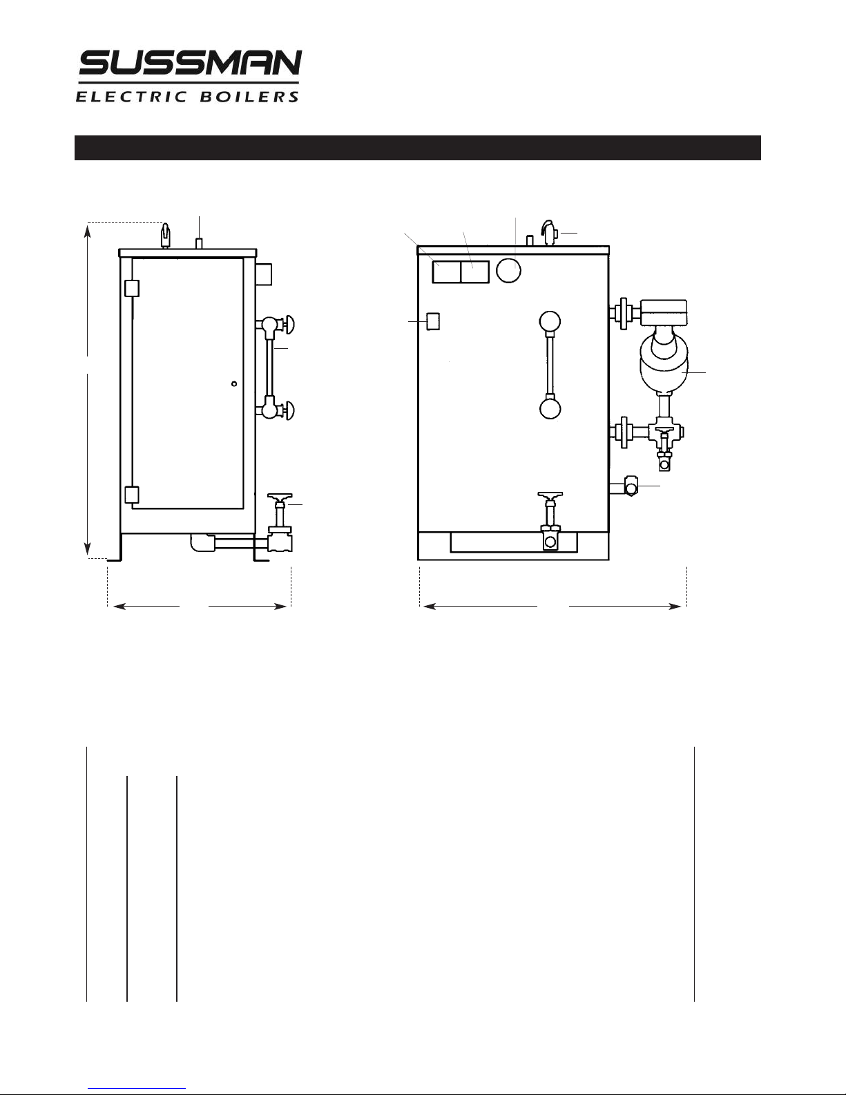
Dimensional & Clearance Specifications
Height
SteamOutlet
Operating
Pressure
A
Gauge Glass
Assembly
Control
On/Off
Switch
High Limit
Pressure
Control
D
E
L
Pressure
Gauge
SafetyValve
LiquidLevel
Control
E
R
B
Water Feed Inlet
Drain Valve
FrontLeft
Width Length
F
Side Elevation Front Elevation
Allow 24" all around for servicing.
__________________________________________________
Clearance from combustible surfaces
__________________________________________________
A
_________________________________________________________________________
B
_________________________________________________________________________
D
_________________________________________________________________________
EL
_________________________________________________________________________
ER
_________________________________________________________________________
F
_________________________________________________________________________
G-
_________________________________________________________________________
1" Clearance above top of boiler
A Clearance from Front of boiler. Prefix "C" to numeral indicates acceptability for
closet or alcove installations; prefix acceptability for alcove installations but not
for closet installations.
1" Clearance from back of boiler.
1" Clearance from left side of boiler.
16" Clearance from right side of boiler.
C Indicates type of flooring: "NC" for non-combustible; "C" for combustible.
Total minimum free area in square inches of close ventilating openings.
3
Page 4
H1 H3 H5 H7
FB1 FB2 FB3 FB4
FIELD WIRING
FACTORY WIRING
PILOT
LIGHT
480V
120V
H2 H4 H6 H8
TO CONTROL
CIRCUIT
HEATING
ELEMENTS
TRANSFORMER
(optional)
TB 1
TB
FB
C
H
L1
L2
L3
G
POWER FUSES
(see Note 2)
CONTACTORS C1 C2 C3 C4
SINGLE PHASE
MAIN POWER SUPPLY
L1 L2 G
T1
TERMINAL POWER BLOCK
(see note 1)
THREE PHASE
MAIN POWER
SUPPLY
Installation, Operation & Maintenance Manual
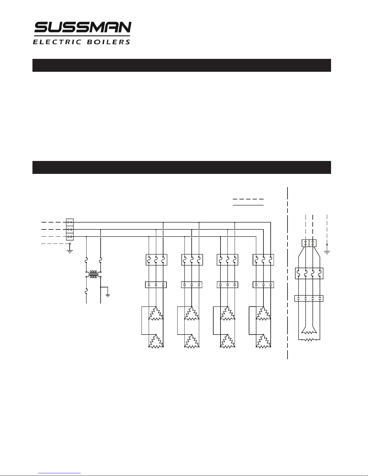
Typical Wiring Diagrams:
a.
Three phase power circuit with separate 120Volt control circuit. (With singe phase power circuit insert.)
b.
Three phase power circuit with step down transformer.
c.
Detailed ES81017MR auxiliary low water cut off wiring.
d.
ES81600 Auto blowdown wiring diagram.
e.
Detailed sequencer package wiring diagram.
Wiring Diagram Power Circuit
ES Electric Boilers (Power Circuit)
NOTES:
1. Power Terminal Block only on boilers with two or more contactors.
2. On boilers with only one power contactor, connect power voltage to line side of contactor.
3. Power Fuses only on boilers rated 120 amperes and larger.
4. See Parts List for contactor and heating element information.
4
Page 5
RELAY
FIELD WIRING
FACTORY WIRING
PILOT
LIGHT
L
OPERATING
PRESSURE
CONTROL
AUX LWCO
PC BOARD
MANUAL RESET
PILOT
LIGHT
L1
G
NC
COM
NO
L2
HIGH LIMIT
PRESSURE
CONTROL
LIQUID
LEVEL
CONTROL
ON-OFF
SWITCH
CONTROL
TERMINAL
BLOCK
120V 1PH
INPUT
L
N
TO
PROBE
SOLENOID VALVE
CONTACTORS
PUMP MOTOR
P2
P1
R
C1
C2
S
M
GND
LOW
RESET
RELAY
FIELD WIRING
FACTORY WIRING
PILOT
LIGHT
L
OPERATING
PRESSURE
CONTROL
HIGH LIMIT
PRESSURE
CONTROL
LIQUID
LEVEL
CONTROL
ON-OFF
SWITCH
CONTROL
TERMINAL
BLOCK
120V 1PH
INPUT
L
L1 L2
N
SOLENOID VALVE
CONTACTORS
PUMP MOTOR
P2
P1
R
C1
C2
S
M
Installation, Operation & Maintenance Manual
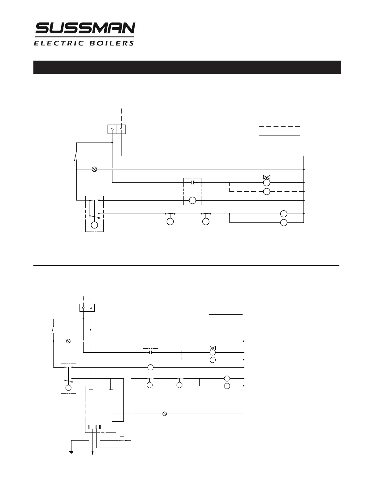
Wiring Diagram Control Circuit
ES Electric Boilers (Basic Control Circuit)
ES Electric Boilers with Manual Reset Auxiliary Low Water Cutoff
5
Page 6
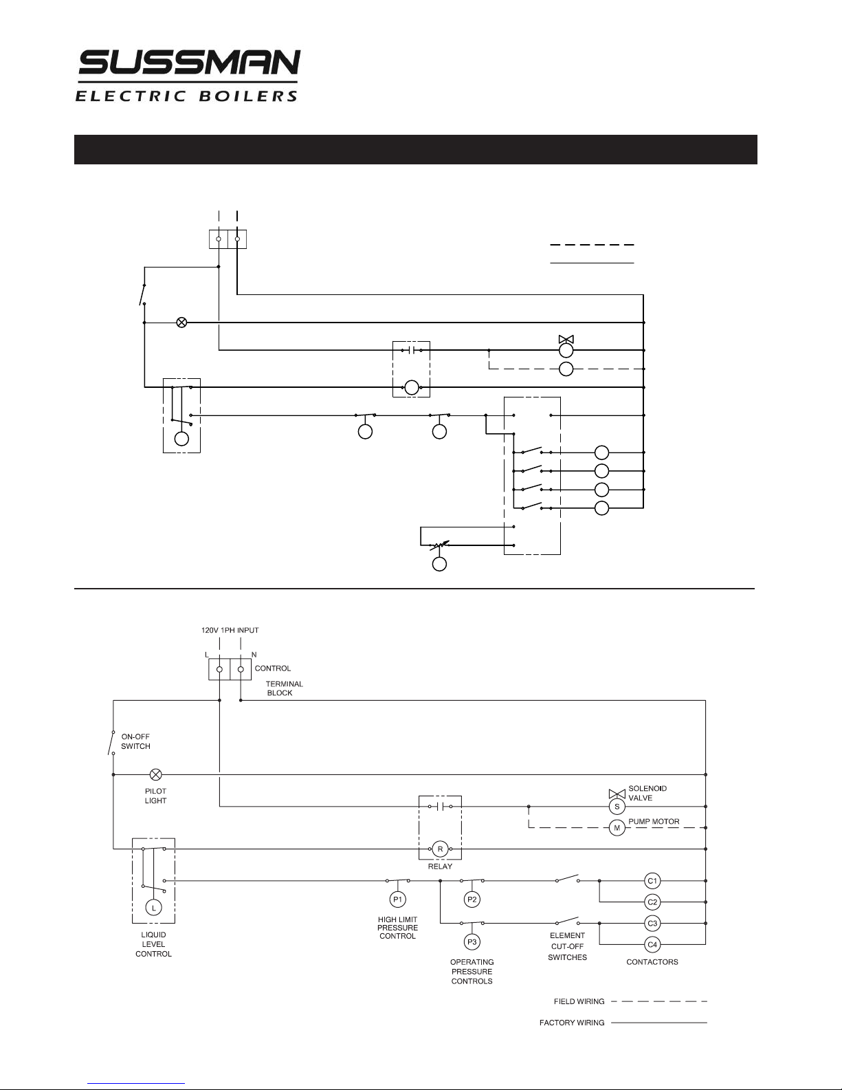
Wiring Diagram Control Circuit
RELAY
F
IELD WIRING
F
ACTORY WIRING
P
ILOT
L
IGHT
L
OPERATING
PRESSURE
CONTROL
PROPORTIONING
PRESSURE CONTROL
135 OHM
COM
SEQUENCER
HIGH LIMIT
PRESSURE
CONTROL
LIQUID
LEVEL
CONTROL
ON-OFF
S
WITCH
CONTROL
TERMINAL
BLOCK
120V 1PH
I
NPUT
L
N
L1 L2
SOLENOID VALVE
C1
C2
C3
C4
CONTACTORS
1
2
3
4
P
UMP MOTOR
P2
P3
P1
R
1
20V COM
M
S
M
Installation, Operation & Maintenance Manual
ES Electric Boilers with Sequencer
ES 100 and up with Element Cutoff Switches
6
Page 7
RELAY
F
IELD WIRING
F
ACTORY WIRING
PILOT
LIGHT
PILOT LIGHT
L
OPERATING
PRESSURE
CONTROL
HIGH LIMIT
PRESSURE
CONTROL
LIQUID
LEVEL
CONTROL
O
N-OFF
SWITCH
CONTROL
T
ERMINAL
BLOCK
120V 1PH
I
NPUT
L
N
7-DAY 24-HR
T
IMER
TIME DELAY RELAY
E
S81600
AUTOMATIC
BLOWDOWN SYSTEM
C1
C2
CONTACTORS
S
M
SOLENOID VALVE
PUMP MOTOR
P2
P1
R
2
OPEN
CLOSE
3
D
T
M
OTORI ZED
B
LOWDO WN
VALVE
1
Installation, Operation & Maintenance Manual
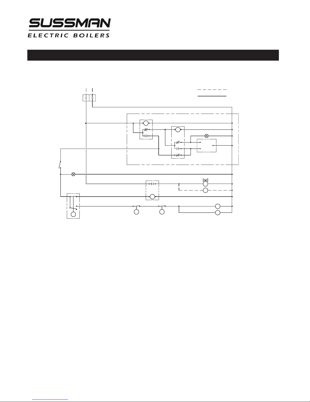
Wiring Diagram Control Circuit
ES Electric Boilers with Automatic Blowdown System
7
Page 8

Installation, Operation & Maintenance Manual
Installation
REFER TO NATIONAL AND ALL APPLICABLE LOCAL CODES FOR SPECIFIC INSTALLATION
REQUIREMENTS.
1. The boiler should be mounted on a solid, level foundation.
2. The boiler should be located with suitable clearances, refer to page 3 and Code requirements.
NOTE: Allow minimum of 21 inches clearance in front of door for servicing of heating elements.
3. Do not install boiler in any location where water could freeze.
4. Do not install boiler outdoors.
5. Do not install boiler near flammable or corrosive materials.
6. Do not install boiler in a location where leakage from the boiler tank or piping can damage to
adjacent areas or to lower floors of the structure. Provide a floor drain and properly sloped floor
from the boiler towards the drain or install a suitably plumbed drain pan under the boiler.
NOTE: Allow a minimum of 36 inches of clearance in front of door for servicing of heating elements.
Piping
ALL PIPING SHOULD BE INSTALLED BY A QUALIFIED LICENSED PLUMBER
IN ACCORDANCE WITH NATIONAL AND LOCAL CODES.
1. When water feed is other than pump type the water supply pressure must be 10 psig greater than boil-
er operating pressure to assure water supply maintains proper water level in the boiler. Insufficient
water levels can result in improper boiler operation. (Keep feed water valves open at all times during
normal operation.)
2. If pump and boiler are plumbed within 30 feet (pipe length) a minimum of 2 check valves are required
to avoid damage to pump.
3. Connect steam line with customer supplied outlet valve to boiler steam outlet.
NOTE: For best performance, a globe valve rated for steam service higher than the maximum boiler pres-
sure should be plumbed on the steam outlet line; failure to do so can cause heating element breakdown.
See page 1 for steam outlet valve size.
4. Provide for boiler drain connection, a daily blowdown is required. A "Blowdown Separator Tank" may
be necessary, check with local code.
5. Safety valve shall be plumbed according to local code.
NOTE: The safety valve shall not be plumbed with a line sized less than the outlet size of the safety valve.
8
Page 9

Installation, Operation & Maintenance Manual
Wiring
ALL ELECTRICAL WIRING MUST BE PERFORMED BY A QUALIFIED ELECTRICIAN
IN ACCORDANCE WITH NATIONAL AND LOCAL ELECTRICAL CODES.
CAUTIO N
!
matches the power voltage and phase of the boiler. Connecting incorrect power supply can
damage boiler components or cause improper boiler operation. If the boiler power
requirements do not match the power to be supplied to the boiler the boiler must be
returned to the factory for conversion. Boilers cannot be field converted.
ALL BOILERS ARE PRE-WIRED AND TESTED PRIOR TO SHIPMENT.
1.
Ground boiler according to National Electric Code
requirements to avoid shock.
2.
Power wiring to boiler should be in accordance with
National and Local Electrical Code requirements following wiring diagram supplied. Use proper size wire.
Wire size is specified adjacent to field wiring terminals.
This label states the wire size [AWG or MCM], minimum temperature rating (90 C) and conductor material
(copper only). Deviation from these requirements may
result in improper or unsafe boiler operation.
3.
A disconnect switch employing circuit breakers or
fuses should be installed between the main power
source and the boiler. This disconnect switch should be
located near the boiler and clearly marked for easy
access and identification should the boiler need to be
turned off due to an emergency.
4.
Boiler control circuit is 120 Volt*. Unless boiler has an
optional step down transformer, a separate 120 Volt
power feed wiring is required to be connected to the
control circuit terminal block. A 15 Amp circuit is
required for all boilers. If a 3/4 HP feed water motor
and pump assembly is connected to the boiler, then a
20 Amp circuit is required.
Assure that the power voltage and phase being supplied to the boiler
5.
If a separate control circuit is used, it should be connected to the control circuit terminal block.
6.
Remote mounted water feed systems (i.e. condensate
return, motor and pump) should be connected to the
junction box provided on the outside of the boiler
jacket.
7.
With main power off, make sure all wiring terminations are tight to avoid arcing, carbonizing or overheating of contacts.
CAUTIO N
!
damage due to water line connections. An industrial type
lightning/surge protector should be installed according to
the manufacturer's recommendation at the service
entrance. Consult your contractor or electrical dealer.
WARN I N G
!
cation of wiring system voids the warranty and may lead
to dangerous operating conditions.
Boilers are susceptible to lightning
Substitution of components or modifi-
9
Page 10

Installation, Operation & Maintenance Manual
Pre-Operation Check (All Boilers)
LWCO/PUMP CONTROL OPERATION AND TESTING
1.
All valves for incoming water supply are to be fully opened.
Main disconnect switch is to be in the "on" position. Boiler main
switch is to be in the "on" position. Since boiler will be empty
the pump or solenoid will be energized allowing the boiler to
fill with water. Control will automatically fill boiler to proper
operating water level and the pump/solenoid will be de-energized. Contactors will then energize, applying voltage to the
heating elements.
2.
Pump switch operation – at this point water should be visible
approximately half way up the sight glass. Slowly open the
drain valve located at the bottom of the boiler. Water level in
the sight glass will begin to drop, allowing the low water cut
off/pump control to energize the feed water system. Close valve
for proper operation.
3.
Low water cutout switch performance – open the drain valve
completely. Maintain this condition until water level falls within
the gauge glass enough to cause the low water cutout switch to
de-energize the heating elements. All of the contactors will be
in a de-energized or open state at this time. Close the drain
valve, water feed system will automatically refill the boiler and
the contactors will re-energize.
Pressure Controls, Operation and Testing
Boilers equipped with an auxiliary low water cut-off
control with a manual re-set button (required as
mandatory equipment is some states): once the correct
operating water level has been reached, it will be necessary to depress the reset button in order for the contactors to re-energize.
NOTE:
down system:
• For test 1 - the blowdown time clock must be in the
• For test 2 and 3 - in order for the drain valve to open
For boilers equipped with an automatic blow-
“run” mode before the boiler will automatically fill.
the blowdown clock must be in the “off” mode.
(See blowdown time clock insert) The automatic
blowdown indicator light will be on when the valve
is open. This light will remain on for the duration of
the blowdown cycle (a few seconds). It may be necessary to cycle the time clock from the “run” to
“off” mode several times.
NOTE:
All boilers are provided with one high limit
pressure control and at least one operating pressure
control.
1.
The high limit pressure control is equipped with a manual
reset feature. There is no subtractive differential scale
with this type of control
2.
All pressure controls are equipped with an adjusting
screw, allowing for setting of desired operational and
high limit pressures. To reduce pressure setting, turn
adjusting screw in direction that allows indicator to point
to a lower pressure setting on the scale. To increase pressure setting turn adjusting screw in direction that allows
indicator to point to a higher pressure on the scale
NOTE:
10 psig above the desired normal operating pressure.
3.
It is recommended that the high limit control be set
Operating pressure controls, except low pressure (15psig)
types have a separate differential scale. Differential indicates pressure below the main operating maximum pressure, the pressure control will re-set. The differential set
point is adjusted in the same manner by turning the
adjusting screw in the desired direction to increase or
decrease the differential pressure value.
4.
Operating pressure control check: Close steam outlet
valve [supplied by customer] and adjust operating pressure control to 20psig and the differential to 10psig.
Set the high limit pressure control to 30psig. Switch
boiler on to allow steam pressure to build-up. Pressure
gauge reading will increase and the operating pressure
control will de-energize the contactor(s) when the pressure gauge indicates 20psig. Open steam outlet valve
to bleed off pressure. When the pressure gauge reading decreases below 10psig (differential) the operating
pressure control will re-energize the contactor(s).
5.
High limit pressure control check: FOR TEST PURPOSES
ONLY! Set the high limit pressure control 10psig lower
than the operating pressure control. Close the steam
outlet valve and switch the boiler on to allow boiler to
build pressure. When the pressure gauge indicates the
pressure at which the high limit pressure control is set,
the high limit pressure control re-set button will popup and the control will de-energize the contactor(s).
Open the steam outlet valve to bleed off pressure. The
contactor(s) should not re-energize on pressure drop.
The contactor(s) should only re-energize when the pressure has dropped and the high limit pressure control
reset button is depressed.
10
Page 11

Installation, Operation & Maintenance Manual
Operation
CAUTIO N
!
lectrical connections before energizing boiler to prevent
e
arcing, carbonizing of contact and/or overheating
1. Set the desired operating pressure and differential pressure
on the operating pressure control.
2. Set the high limit pressure control. (Recommended to be
10 psig above the operating pressure setting.)
3. Turn on water supply.
4. Turn main disconnect switch on.
5. Turn boiler control switch on. The water feed will begin
and continue until the water level reaches half way up the
gauge glass. The water feed will automatically shut off and
the contactor(s) will energize.
6. Boiler steam pressure will gradually increase to the operat-
With main disconnect “OFF” tighten all
ing pressure control set point, at which time the contactor(s) will de-energize.
7. With steam demand, the boiler steam pressure will
decrease. When the boiler pressure has dropped below
the operating pressure control differential set amount,
the contactor(s) will re-energize.
Note: Adjust steam outlet valve such that the boiler pressure does not drop more than 20% below reset.
8. The boiler is equipped with float type liquid level controls employing micro switches. They are extremely
sensitive and reliable and will maintain the proper
water level within the boiler pressure vessel automatically during boiler operation.
9. The boiler should be blown down daily. (See blowdown instructions.)
Blowdown
A daily blowdown is an essential part of boiler operation.
It is the best and most important part of preventative
maintenance you can give your boiler and will add years
of life to the unit. Make sure a blowdown schedule is
established and followed regularly.
In extremely hard water areas, blowdown may be necessary
more than once a day. If there is a particular problem
that applies to your local water condition (i.e. high concentrations of minerals etc.) we recommend a consultation with a
reputable local water treatment-engineering firm. Pre-treating
the boiler feed water may reduce mineral accumulation
enough to allow a daily blowdown to be sufficient.
MANUAL BLOWDOWN INSTRUCTIONS
1. At the end of the working day, while boiler is still operating,
turn boiler main switch to the “OFF” position, close water
supply valve and open disconnect switch.
2. If blow down valve is plumbed into a blowdown tank, the
boiler can be discharged at operating pressure.
3. If the blowdown valve is not plumbed into a blowdown tank,
consult with local plumbing codes regarding boiler discharge.
4. When discharge is complete and boiler is drained, close the
blowdown valve, open the water supply valve, turn boiler
main switch to “ON” position and close disconnect switch.
5. When refilling is complete, turn off the boiler unless further
operation is needed.
6. If boiler is equipped with a “Manual Re-set Auxiliary Low
Water Cut-off” (as required in some states) the re-set button
must be pushed before the boiler will begin developing
steam. Do not push re-set button until the boiler has refilled
with water.
AUTOMATIC BLOWDOWN INSTRUCTIONS
(PN ES81600) 1” NPT, Starts, stops and blows down the
boiler automatically, utilizing a programmable time clock
a time-delay relay and motorized ball valve.
CAUTIO N
!
a blowdown tank, the boiler can be discharged at operating pressure. If the blowdown valve is not plumbed into a
blowdown tank, consult with local plumbing codes
regarding boiler discharge.
NOTE:
lower float control equalization tube must be fully open
for the automatic blowdown to be effective.
1. Program time clock by setting the time boiler is to turn
2. When the time clock turns the boiler “off” the blow-
3. Boiler will automatically refill at next programmed on
Blowdown program can be overridden to allow for
unscheduled blowdown or operational cycles. Refer to the
time clock instruction insert.
11
The manual valves from the boiler drain and the
on and off daily. (Refer to instructions in time clock
insert.)
down is activated. A red pilot light over the time clock
will come on and remain on while the motorized ball
valve is open. The time duration the valve is open is set
by an adjustable potentiometer built into the time delay
board. The water level in the boiler after blowdown is
complete, will be approximately at the lower gauge
glass valve. (Elements are not exposed to air between
operations.)
cycle.
If the blowdown valve is plumbed into
Page 12
Installation, Operation & Maintenance Manual
Mo
Tu
We
T
h
Fr
S
a
Su
14
16
18
20
22
24
+- Menu OK
Res.
+1h
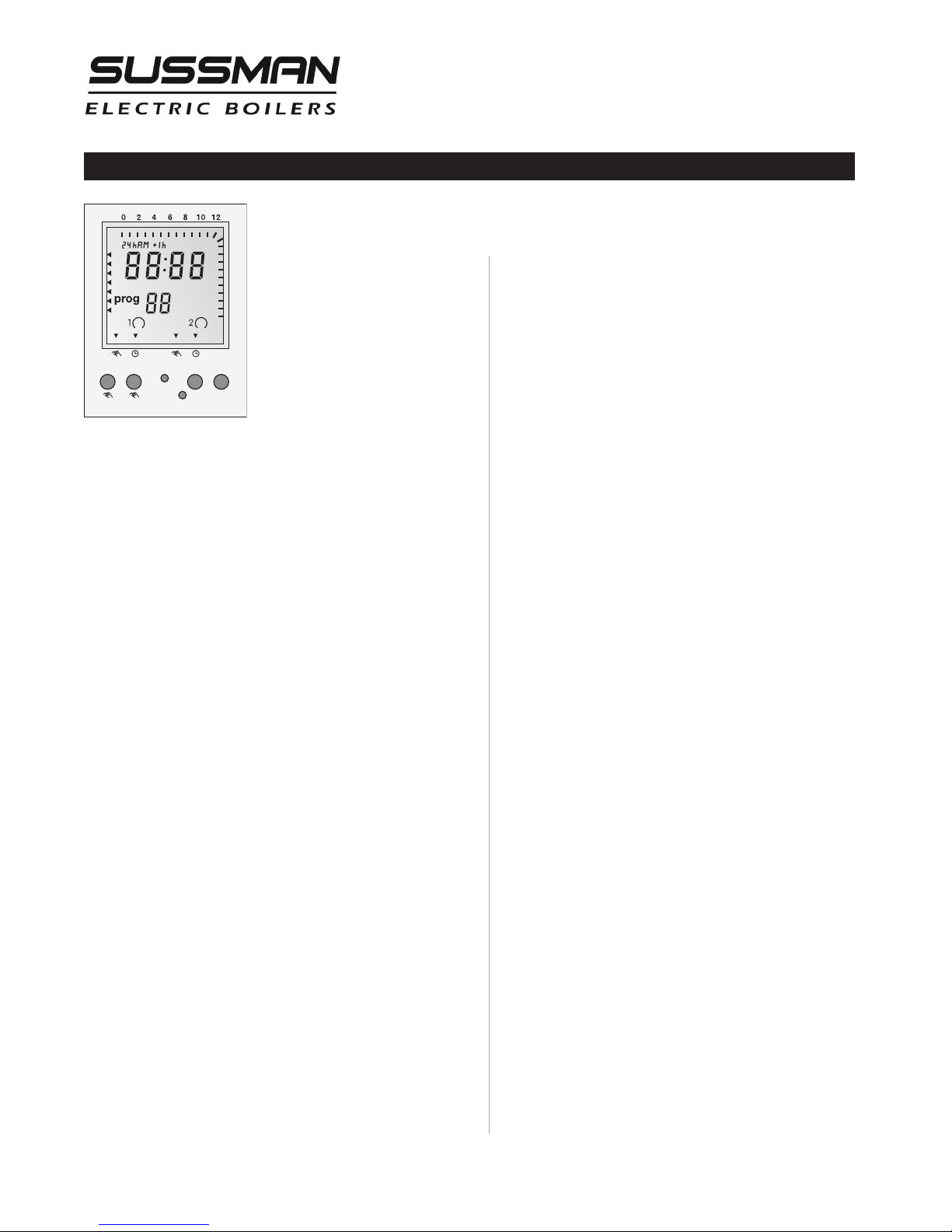
Digital Timer - Operation Instructions
TO SET TIME & DAY OF
CLOCK
1. Press Menu
2. 24h AM or PM blinking, press
+ or – to select, press OK
3. Hour (12:00) blinking, press +
or – to select, press OK
4. Minute (12:00) blinking, press
+ or – to select, press OK
5. Arrows for days
press + or – to select, press OK
6. Go to step 8 to continue with programming or press
Menu to end.
TO SET TIMER ON/OFF TIMES
7. Press Menu and press OK four times to go
current time/day setting above
8. prog 01 blinking and ON symbol
or – to select, press OK
9. Hour (12:00) blinking, press + or – to select, press OK
10. Minute (12:00) blinking, press + or – to select, press
OK
11. Arrows for days
blinking, press + or – to select,
press OK
12. prog 02 blinking and
OFF
symboldisplayed,
press + or – to select, press OK
13. Hour (12:00) blinking, press + or – to select,
press OK
14. Minute (12:00) blinking, press + or – to select, press
OK
15. Arrows for days
blinking, press + or – to select. See
possible combinations below.
16. Press Menu to end or press OK and repeat steps 8 to
15 to set more ON/OFF times.
displayed, press +
blinking,
ON/OFF STATUS
ON
symboldisplayed when timer isonand
OFF
symboldisplayed when timer is off.
OVERRIDE/AUTOMATIC
When the timer is
the timer
OVR
arrow
Offand display arrowwill point to
. Press + again to go back to
will point to
When the timer is
the timer
OVR
Onand display arrowwill point to
.
Press + again to go back to
will point to
When the timer is in the override mode
timer will stay in that position until the next programmed time, at which time the arrow_will point
to
AUTO
and continue in the automatic mode.
On, press + to manually turn
Onand display
AUTO
.
Off, press + to manually turn
Offand display arrow
AUTO
.
(on
OVR
HOURLY ON/OFF SETTING FOR THE DAY
Hash marks on the upper and right edges of the display show the hourly On times for the day. Absence
of hash mark on a specific hour indicates that the
timer is Off on that hour.
DAYLIGHT SAVING TIME.
In the Run mode, use a pencil point and press+
for Daylight Saving Time and current time advances
hr
one hour and +
Standard Time, press +
one hour and +
displayed. To revert back to
hr
and current time falls back
hr
display disappears.
hr
),
PROGRAMMED DAY COMBINATIONS:
Every day (arrowson all days)
Monday to Saturday
Monday to Friday
Saturday and Sunday
Any individual day
RUN MODE
On Run mode, display will show current time/ date, on/off
status, override/automatic status, hourly on/off setting for
the day and Daylight Saving Time.
PROGRAMMING CONFLICTS.
Switch Off commands have priority over switch On
commands.
NOTES:
1. The timer is set according to the boiler operation.
ON
When the timer is
blowdown is
OFF
the boiler is
.
2. Timer must be powered up during programming
to display
On/Off
status.
3. During programming, if no button is pressed after
1 minute, the timer will revert back to Run mode.
12
ON
and the
Page 13
Installation, Operation & Maintenance Manual
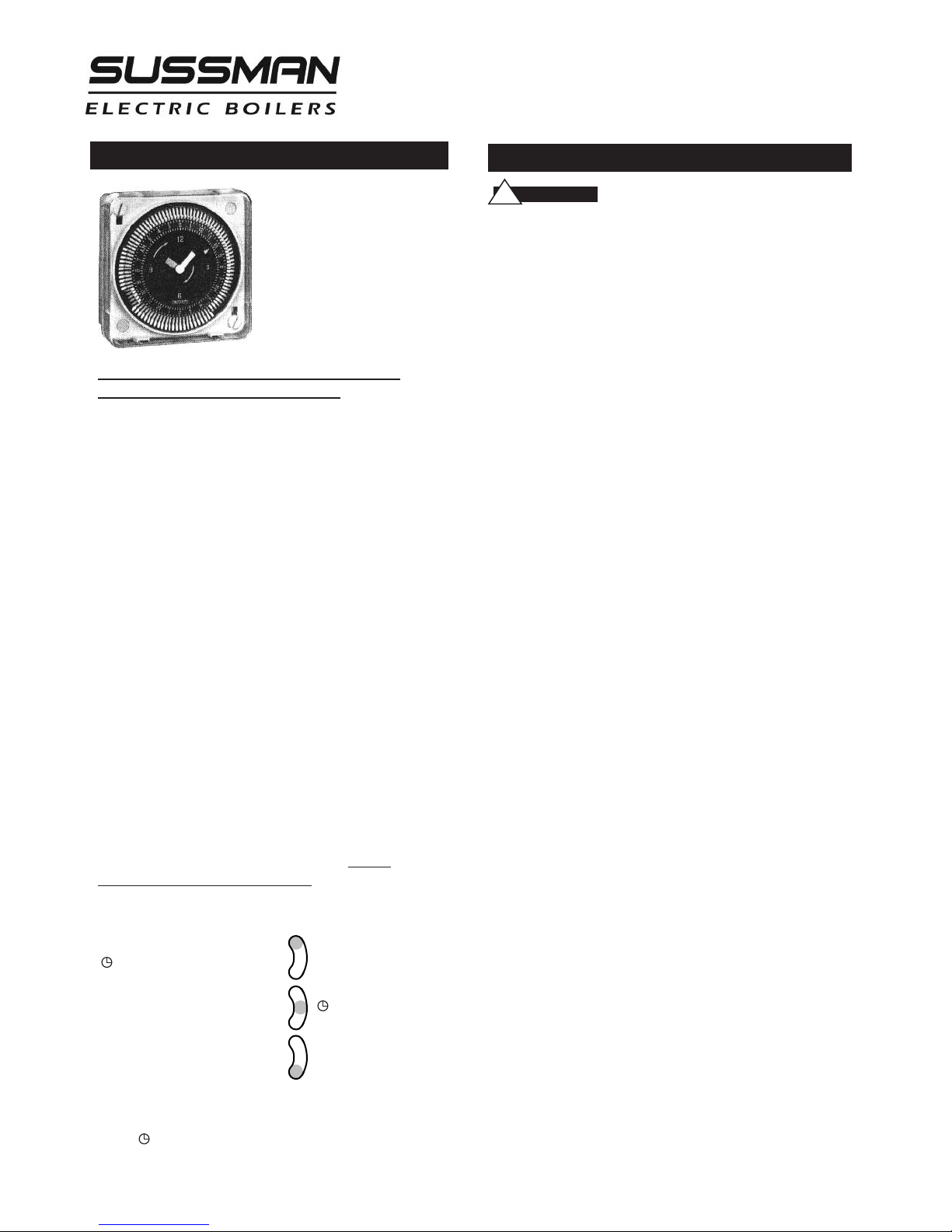
24-Hour and 7-Day Time Switches
PROGRAMMING
F
or electric steam boilers
equipped with Automatic
Blowdown Systems
ES 81600, refer to the
following instructions
for time clock operation
and settings.
Timer settings for blowdown operation are at
the discretion of the owner/operator.
The weekly program dial shows the seven days of
the week and AM/PM imprints for each day.
The time switch is set by pushing the captive trippers
to the outer ring position for the entire period that
the load is to be turned ON, i.e., 2 hours to each tripper on the 7-day dial. When the tripper is pushed to
the inside, the switch is in the OFF position.
SETTING TIME
To set the current time and day of week, turn
the minute hand clockwise. Do not set the time
by rotating “Outer” Dial.
Turn the minute hand clockwise until the day of
the week and the time of day on the outer dial is
aligned with the triangle marker on the inner dial
(two o'clock).
AM
Example for 7-day program dial Monday 10:30
Turn the minute hand clockwise until Monday 10:30
AM
is aligned with the triangle on the inner dial.
The hour and minute hand will show exactly 10:30.
FOR MANUAL OVERRIDE
Manual override can be accomplished at the
discretion of the owner/operator as follows.
3-WAY MANUAL OVERRIDE SWITCH
I = permanent ON
= automatic
O = permanent OFF
I
O
.
Maintenance
CAUTIO N
!
DISCONNECT ALL ELECTRICAL POWER BEFORE
WORKING ON BOILER.
ussman Electric Steam Boilers are designed for years of trou-
S
ble-free performance. To establish a good preventative maintenance program, we suggest that the facility maintenance person or engineer familiarize themselves with these simple rules.
1.
Daily blowdown at pressure is essential for ideal boiler
performance. Extended periods of operation may require
more frequent blowdown. If the boiler is not equipped
with an automatic blowdown, in order to safeguard the
heating elements, it is recommended to turn both the main
disconnect switch and the boiler switch to the off position
before manually blowing down the boiler.
2.
The sight glass should be checked frequently to assure the
boiler has adequate water.
3.
The sight glass should be checked daily for damage (i.e.
scratches, erosion, leaks etc.) The sight glass should be
replaced if damaged. (See insert.)
4.
A monthly inspection should be made of the internal wiring.
Open the access door and check all electrical connections
for tightness. Replace any wires that show signs of damage.
NOTE:
this maintenance procedure.
5.
6.
7.
8.
The electrical power MUST be shut off during
Heating element mounting bolts should be checked and
tightened to a torque of 22 ft.-lbs. If there are indications
of steam leaks from an element, replace the element
gasket.
A monthly check for leaks should be made; any loose or
damaged fittings should be tightened or replaced.
Every four months the boiler float control should be
checked for proper operation. The lower equalization
column can be examined visually and manually to see if is
clear and clean. If there are signs of scale or mineral
deposit buildup the float control must be disassembled and
cleaned.
One of the lower heating elements should be removed. If
scale or mineral deposits have begun to form all elements
should be removed cleaned and reinstalled using new
element gaskets.
Operating and high limit pressure control operation should
be checked. Pressure controls should be removed and
cleaned if necessary. Water feed supply check valves should
be inspected and replaced if necessary.
If the boiler is equipped with an electronic auxiliary low
water cut-off every four months the probe should be
removed and checked for deposits. The probe should be
cleaned and reinstalled.
HAZARD OF ELECTRIC SHOCK.
IMPORTANT: It is recommended that for periodic
and effective blowdown,the override switch be set
in the automatic setting.
13
Page 14

Installation, Operation & Maintenance Manual
Standard Equipment for ES & HU Optional Equipment
AUXILIARY LOW WATER CUT OFF
• For model ES & HU boilers PN ES81017MR
(with manual reset).
Senses water level electronically using a resistance probe.
When a low water condition is detected, the contactor
control voltage circuit is interrupted and the heating
elements are de-energized. When water level returns to
proper levels voltage is restored to the contactor coils
and the elements are re-energized. For controls with a
manual reset button voltage to the contactor coils is not
restored until the water level has returned to proper
operating levels and the reset button is pushed. Do not
depress the reset button before the correct water level
is achieved.
LINE PRESSURE WATER FEED SYSTEM
• For model ES & HU boilers PN ES99117
Water feed system used to supply makeup water to the
boiler when incoming water line pressure is 10 psig
greater than the operating pressure of the boiler.
Completely factory plumbed and wired; 0-100psig range;
1/2” NPT size. Consists of strainer, solenoid valve
(120/1/50-60Hz), and check valve for automatic feed.
HIGH PRESSURE WATER FEED SYSTEM
• For model ES12-72 PN ES38002A
• For model ES100-180 PN ES38020A
Used to supply makeup water and to maintain constant
water level when the boiler operating pressure is equal to
or greater than incoming water line pressure and condensate is not returned to the boiler.
• ES38002A – Range is 0 – 100 psig, 1/2” NPT size consisting
of strainer, solenoid valve and 1/3 HP 120/1/60 motor and
pump.
• ES38020A – Range is 0 – 125 psig, 3/4” NPT size
consisting of strainer solenoid valve and 1/2 HP 120/1/60
motor and pump.
These assemblies are mounted on rubber shocks and
secured to a steel base mounting plate. These units require
field plumbing and wiring to the boiler.
CONDENSATE RETURN SYSTEM
(see page 16)
• For model ES12-72 PN ES38083V; for model
ES85-180 PN ES38084V.
These systems are used whenever condensed steam can
be collected for reuse in the boiler. Returning the condensate to the boiler can save a significant amount of energy.
The water returned is relatively free of corrosive minerals
and carries a substantial amount of heat that does not
have to be replenished. A vacuum breaker is required
whenever a condensate return system is used.
Each system consists of a vertical condensate return tank,
a motor and pump and support plumbing. A 1/2” inlet is
located on the tank to accept make-up water. A vent fitting is located on the condensate tank top for atmospheric air venting. The return fitting is to be plumbed to the
trapped condensate return line coming from the process.
A gauge glass and valve set are mounted on the side of
the condensate tank. The tank has a ball check valve
internally mounted, and a float arm and float ball assembly that serve mechanically allowing make-up water to
enter the tank as the original supply is used. The pump
discharge outlet is to be plumbed to the boiler check
valve. The tank drain valve should be plumbed to a proper drain line. The motor is required to be wired to the
boiler.
14
Page 15

Installation, Operation & Maintenance Manual
Optional Equipment
ACUUM BREAKER SYSTEMS
V
For model ES boilers PN ES89369
•
(cont.)
A vacuum breaker will prevent a boiler from flooding as a
result of the steam condensing internally and creating a
vacuum after boiler shutdown. The breaker allows air to
enter the boiler shell breaking the vacuum. This system is
a must for boilers connected to a condensate return tank.
The vacuum breaker consists of a spring-loaded disc and
associated piping and is factory plumbed to the boiler.
AUTOMATIC BLOWDOWN SYSTEM
• Extends life of boiler
• Saves labor costs
• Starts the boiler automatically every day
• Shuts down the boiler every day
• Automatically blows down the boiler every day
• Completely programmable, can skip days, different start
and shutdown times, different operational durations.
• ES81600 for all model boilers.
A stainless steel, motor driven straight-through, self-clean-
ing ball valve with Teflon seats handles particles and dirty
fluid without the use of an up-stream strainer or other
cleaning device. A timer (Standard analog time clock is set
for two hour time intervals, optional digital time clock
can be programmed to one minute intervals.) and electronic time delay relay control the boiler and the blowdown valve.
A pilot light indicates when the blowdown valve is open.
The valve shall be plumbed to a proper drain or receptacle. An automatic blowdown system can be installed on
any boiler, regardless of size operating pressure or operating duty cycle.
CONTROL VOLTAGE STEPDOWN
TRANSFORMER
• Provides 120 Volt (220 Volt export) from main power
supply. Factory wired and fused.
BLOWDOWN SEPARATORS
(see page 17)
• For models ES12-48 - PN BDT-ASME36
• For models ES60-180 PN BDT-ASME42
A separator accepts the flash steam and effluent from the
boiler blowdown and reduces the temperature and pressure
to insure a safe discharge of water and sludge. Steam flash
and pressure are absorbed and pass harmlessly to the outside via a vent. The separator design utilizes a water seal at
the outlet, which permits the operator to introduce cold
water from the bottom to mix with the hot water and boiler
steam in the blowdown separator. This reduces outlet temperature to a safe discharge level.
These separators require specific plumbing from the boiler
blowdown valve and require connection to a cold water supply. (If the separator is less than half full of water after the
boiler is blown down cold water must be added to bring the
water level to the halfway mark before the next blowdown).
• 0-30 psig pressure gauge; 0-200F temperature gauge; water
sight gauge glass and valve set assembly are included.
MULTISTAGE LOAD PROGRESSIVE
SEQUENCERS
Accurate control is provided by automatic progressive sequencing in the use of energy and minimizing wear on electrical
components. The sequencers are designed to apply power progressively to larger KW boilers. A factory installed pressure sensitive sequential control reacting to steam boiler pressure progressive energizes or de-energizes heating elements through
power contactors. A delay between sequencer steps before
start-up and between each subsequent step eliminates power
surges. Each sequencer is matched and factory pre- set to boiler system requirements. Electronic progressive sequencers give
accurate control of multi-stage loads of the type used in steam
boilers. Features include progressive sequencing (first on- first
off) that equalizes the operating time of each load. Integral
solid-state light emitting diodes show active stages. Should a
power interruption occur, all elements are instantly deenergized for safety. Upon resumption of power the control
will re-stage the loads one at a time.
15
Page 16
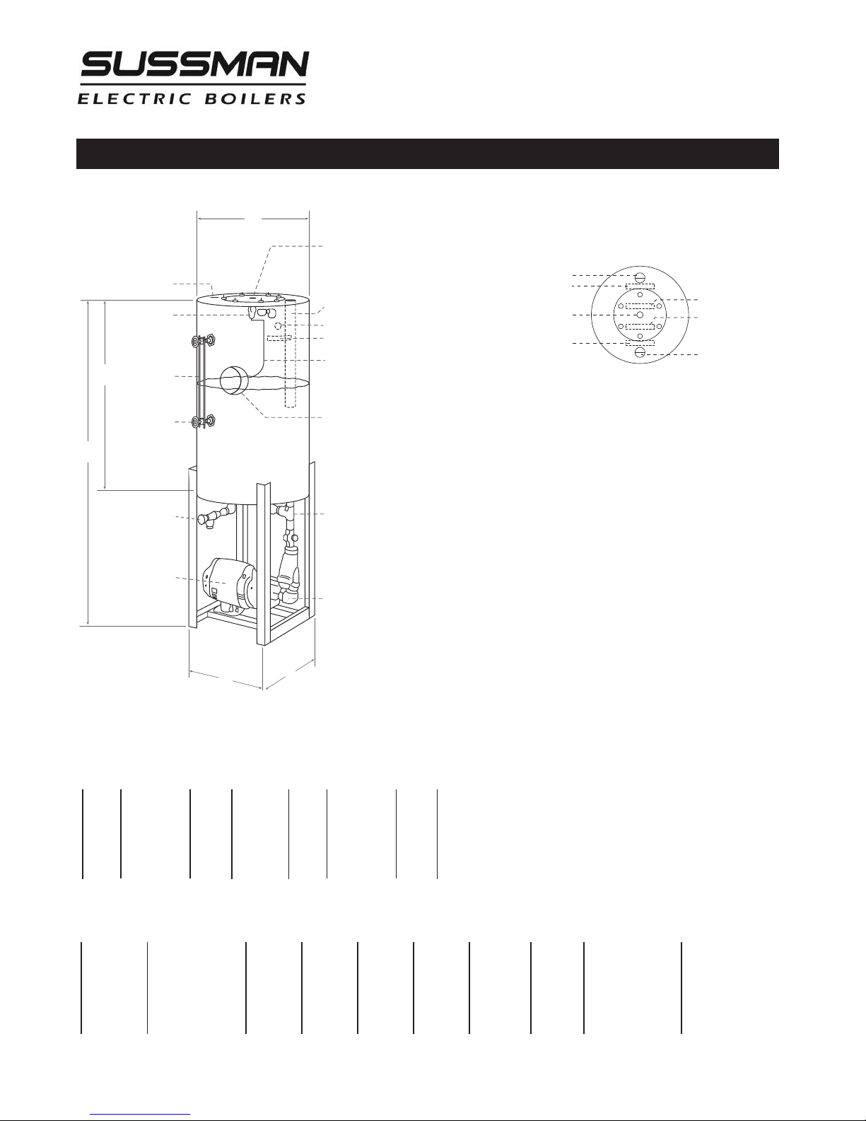
Condensate Return Systems
B
E
A
D
C
9
-
1
/2"
DIA COVER PLATE
EASY ACCESS FOR MAINTENANCE
C
ONDENSATE RETURN FLASH TUBE
OVERFLOW OUTLET 1" NPT (farside)
O
VERFLOW (label)
S
IMPLE RUGGED LINKAGE
5" DIA UPPER FLOAT BALL
39011FB
SHUTOFF GATE VALVE
STRAINER CLEANOUT
V
ENT SAFETY BAR
F
LOAT VALVE
39010-F
7-
7
/8"
SIGHT GLASS
99074-1
S
ITE GLASS ASSY
PN 99173C
1
/2" DRAIN VALVE
PUMP EASY ACCESS
1-1/4" VENT WITH SAFETY BAR
V
ENT (label)
1/2" COLD WATER INLET COUPLING
WITH #100 MESH STRAINER
C
ONDENSATE RETURN (label)
TOP VIEW
C
OLD WATER INLET
(
label)
LIMIT MAKEUP WATER PRESSURE
TO TO 30 PSI MAXIMUM” (label)
1-
1
/4" CONDENSATE
RETURN COUPLING
Models 38083V & 38084V
Installation, Operation & Maintenance Manual
Notes:
1.
Motor/Pump is closed - Coupled design
2.
Pump capacity as follows:
MODEL 38083V
___________________
PSIG HEAD GPM
___________________
54 125 ft. 3.2
___________________
75 175 ft. 2.9
___________________
97 225 ft. 2.7
___________________
3.
Normal cold water level approximately 1/2 to 5/8 up to visible part of gauge glass.
_____________________________________________________________________________
MODEL Used on "A" "B" "C" "D" "E"` H.P. VOLT/PH/HZ
_____________________________________________________________________________
38083V ES12 - ES72 38-1/4" 18 14-1/4" 14 18 1/3 120 / 1 / 60
_____________________________________________________________________________
38084V ES100 - ES180 51-1/2" 18 14-1/4" 14 30 1/2 120 / 1/ 60
_____________________________________________________________________________
MODEL 38084V
___________________
PSIG HEAD GPM
___________________
54 125 ft. 4.6
___________________
75 175 ft. 4.3
___________________
97 225 ft. 4.0
___________________
PUMP MOTOR
16
Page 17
Installation, Operation & Maintenance Manual
D
A
H
G
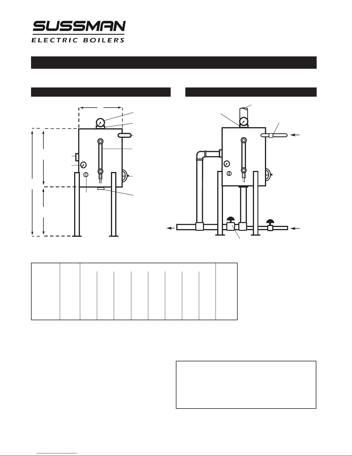
Blowdown Separator Tanks- Specifications and Data
Models BDT-ASME 36, 42, 48, 54
Dimensions and Features Suggested Hook-Up to Boiler
Pressure Gauge
"E"Vent
Blowdown Separator
Ventto atmosphere must be full size
Blowdown Inlet
"B"Inlet
Water Gauge
"C" Drain
Temperature
Gauge
3/4"Coupling
for Temperature
Probe(opt.)
BOILER DIMENSIONS SHIPPING
_______________________________________________________________________
BDT-ASME36 0-5 18" 1" 2" 12" 2" 2" 14" 32" 125
_______________________________________________________________________
BDT-ASME42 6-25 24" 1" 2" 16" 2-1⁄2" 2" 18" 42" 230
_______________________________________________________________________
BDT-ASME48 26-59 30" 1-1⁄4" 2" 16" 3" 2" 18" 48" 260
_______________________________________________________________________
BDT-ASME54 60-100 38" 1-1⁄2" 3" 16" 4" 2" 18" 54" 290
________________________________________________
HP
ABCDEFGHWEIGHT
Handhole Assembly
3"x4"
(exceptBDT-ASME 36)
"F"ColdWater Inlet
&WashoutDrain
Tempered
Blowdown
to Drain
From Boiler
Blowdown Outlets
ColdWater Supply
DrainValve (closed duringnormal operator)
The Sussman Separator design incorporates a water seal at
the outlet which permits the operator to introduce cold
water from the bottom to mix with the hot water and boiler steam blowdown in the separator. This reduces the outlet temperature to a level that makes it safe for discharge.
NOTE:
1BHP is approximately 10KW.
Maximum Boiler Working Pressure: 250 psi
Maximum Blowdown Separator Pressure: 65 psi
Blowdown Separators are sized in accordance with National Board Standards
Standard Equipment
• 0-100 lb. Pressure Gauge
• 0-200˚ Temperature Gauge
• Water Level Gauge
Constructed in accordance with Section VII Division I ASME Boiler
& Pressure Vessel Code
17
Page 18

Installation, Operation & Maintenance Manual
Specifications
__________________________________________
Boiler Bhp Lbs/Hr 3-Ph
Model No. KW Rating Steam** Volts*** Amps
__________________________________________
208 34
ES-12* 12 1.22 36.2 240 29
__________________________________________
ES-18* 18 1.84 54.2 240 44
__________________________________________
ES-24* 24 2.45 72.3 240 58
__________________________________________
ES-30 30 3.06 90.4 240 73
__________________________________________
ES-36 36 3.67 108 240 87
__________________________________________
ES-48 48 4.90 145 240 116
__________________________________________
ES-60 60 6.12 181 240 145
__________________________________________
ES-72 72 7.35 217 240 174
__________________________________________
ES-100 108 11.2 325 240 260
__________________________________________
ES-135 144 14.7 434 240 347
__________________________________________
ES-160 158 16.2 475
__________________________________________
ES-180 180 18.4 542
__________________________________________
* Single phase available
** Steam at 212°F with 50°F feed water. See page 19 for sizing.
*** Other voltage available
480 15
208 50
480 22
208 67
480 29
208 84
480 37
208 100
480 44
208 134
480 58
208 167
480 73
208 200
480 87
208 300
480 130
208 400
480 173
240 379
480 190
240 434
480 217
18
Steam Gauge
Pressure/
Temperature
________________
Gauge Temperature
Pressure
________________
________________________
________________________
________________________
________________________
________________________
________________________
________________________
________________________
________________________
________________________
________________________
________________________
________________________
________________________
________________________
________________________
________________________
________________________
________________________
________________________
________________________
________________________
________________________
________________________
________________________
________________________
________________________
________________________
________________________
________________________
________________________
________________________
________________________
________________________
________________________
________________________
________________________
________________________
________________________
Chart
PSIG
15 179 82
10 192 89
5 203 95
0 212 100
1 215 102
3 221 105
5 227 111
9 237 114
11 241 119
15 250 121
17 253 123
19 257 125
21 260 127
23 264 129
25 267 131
27 270 132
29 273 134
31 275 135
33 278 137
35 281 138
37 283 139
39 286 141
41 288 142
43 290 143
45 292 144
47 295 146
49 297 147
51 299 148
53 300 149
55 303 151
60 308 153
65 312 156
70 316 158
75 320 160
80 324 162
85 327 164
90 331 166
95 335 168
100 338 170
F˚ C˚
Page 19

Installation, Operation & Maintenance Manual
Sizing
Use the following Table to determine KW Boiler rating when steam load and feedwater temperatures are known.
___________________________________________________________________
Feed Water
( F˚)
___________________________________________________________________
40 .3347 .3355 .3375 .3388 .3406 .3422 .3431 .3447 .3458 .3464 .3470
___________________________________________________________________
50 .3318 .3326 .3345 .3359 .3376 .3392 .3401 .3417 .3429 .3435 .3441
___________________________________________________________________
60 .3288 .3296 .3316 .3329 .3347 .3363 .3372 .3388 .3400 .3407 .3411
___________________________________________________________________
70 .3259 .3267 .3287 .3300 .3318 .3334 .3343 .3359 .3370 .3376 .3382
___________________________________________________________________
80 .3229 .3238 .3278 .3271 .3288 .3305 .3313 .3329 .3341 .3347 .3353
___________________________________________________________________
90 .3200 .3208 .3238 .3242 .3259 .3275 .3284 .3300 .3312 .3318 .3324
___________________________________________________________________
100 .3171 .3179 .3199 .3212 .3229 .3246 .3255 .3271 .3283 .3288 .3294
___________________________________________________________________
110 .3142 .3150 .3170 .3183 .3200 .3217 .3225 .3242 .3253 .3259 .3265
___________________________________________________________________
120 .3112 .3210 .3140 .3154 .3171 .3287 .3196 .3212 .3224 .3230 .3236
___________________________________________________________________
130 .3083 .3091 .3111 .3124 .3142 .3160 .3167 .3183 .3195 .3200 .3206
___________________________________________________________________
140 .3054 .3062 .3082 .3095 .3113 .3129 .3137 .3154 .3165 .3171 .3177
___________________________________________________________________
150 .3025 .3032 .3052 .3066 .3083 .3099 .3108 .3124 .3136 .3142 .3148
___________________________________________________________________
160 .2995 .3003 .3029 .3036 .3054 .3070 .3079 .3095 .3107 .3113 .3118
___________________________________________________________________
170 .2966 .2974 .2994 .3001 .3025 .3041 .3050 .3066 .3077 .3083 .3089
___________________________________________________________________
180 .2937 .2945 .2964 .2978 2995 .3011 .3020 .3036 .3048 .3054 .3060
___________________________________________________________________
190 .2907 .2915 .2935 .2948 .2966 .2982 .2981 .3007 .3019 .3025 .3030
___________________________________________________________________
200 .2878 .2886 .2906 .2919 .2937 .2953 .2962 .2978 .2989 .2995 .3001
___________________________________________________________________
0210 15 25 40 50 75 100 125 150
Example:
Note:
Need a boiler to produce 450 lbs. steam/hr. at 75 psig with the available feedwater temperature 50˚ F.
From the chart above, find .3417 KW/Lb. of steam
450 lbs. steam/hr. x .3417= 153.8 KW boiler required
Add 20% to required kW for contingencies
19
Page 20
Gauge Glass Installation
Installation, Operation & Maintenance Manual
IMPORTANT NOTE:
Read all warnings and instructions
before performing installation or maintenance. Safety glasses and gloves should be worn at all times when working
with or examining water gauge glass and connections.
Pressure in generator to be at zero before proceeding.
Improper installation or maintenance of gauge glass and
connections can cause immediate or delayed breakage
resulting in bodily injury and/or property damage.
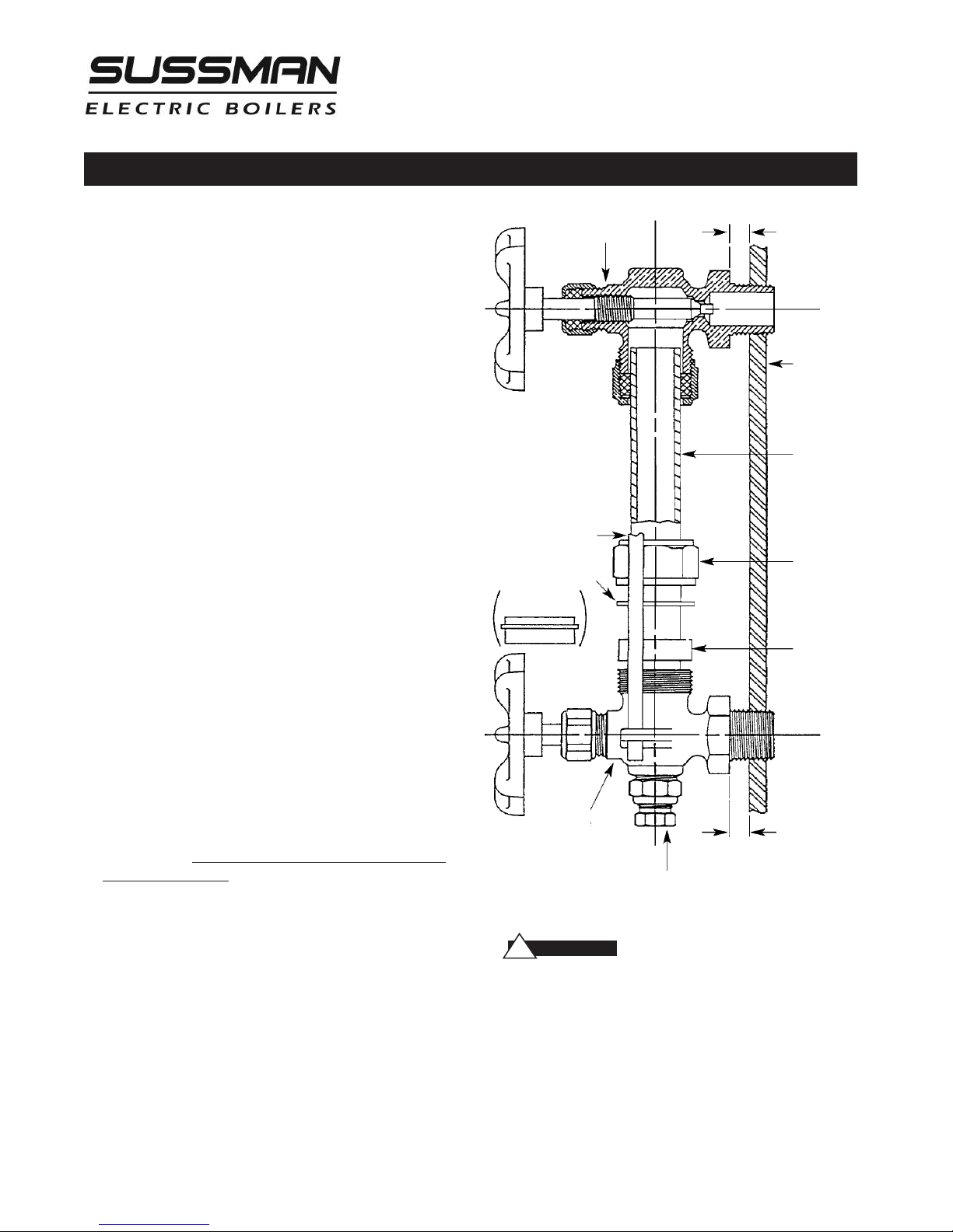
1.
Apply Teflon tape or pipe dope to pipe threads. Install
top gauge fitting (fitting without a drain valve) into the
uppermost tapping. Wrench tighten the fitting until it is
snug and the glass outlet is pointing at five o'clock
(about 1/8 turn from its final downward vertical position).
2.
Install the bottom gauge fitting (the fitting with a drain
valve) until it is snug and the glass outlet is pointing
directly upward. Verify top and bottom fittings are
threaded into the tappings the same number of turns
(distance A= distance B).
3.
Remove glass packing nut, friction washer (or packing
gland, depending upon the model), and glass packing
from the fittings, and place them, in the same order, on
to both ends of the gauge glass. Push both packings
about an inch up the gauge glass.
4.
Gently insert one end of the glass into the top gauge fitting. Keeping the glass inside the top fitting, gently
rotate the top gauge fitting clockwise until vertically
aligned with the bottom gauge, then insert glass into
bottom fitting until glass bottoms out on the shoulder
inside the bottom fitting.
5.
Carefully raise glass about 1/16" and slide lower glass
packing down until the glass packing contacts the lower
gauge fitting. DO NOT allow the glass to remain in contact with any metal!
6.
Carefully slide upper glass packing up as far as possible.
7.
Hand tighten both glass packing nuts, then tighten 1/2
turn more by wrench. Tighten only enough to prevent
leakage. DO NOT OVER TIGHTEN! If any leakage should
occur, tighten lightly, a quarter turn at a time, checking
for leakage after each turn.
IMPORTANT NOTE:
Read all warnings and instructions before performing installation or maintenance.
Top Gauge
Fitting
Guard Rod
Friction Washer
(or Packing Gland)
Bottom
Gauge
Fitting
WARN I N G
!
Drain Valve
Safety glasses and gloves
A
Vessel Wall
Gauge Glass
Glass Packing
Nut
Glass Packing
B
should be worn at all times when working
with or examining water gauge glass and connections.
Pressure in generator to be at zero before proceeding.
Improper installation or maintenance of gauge
glass and connections can cause
immediate or delayed breakage resulting in
bodily injury and/or property damage.
20
Page 21

Installation, Operation & Maintenance Manual
Gauge Glass Installation - Use and Care
O NOTs
D
• DO NOT use glass if it contains any scratches, chips, or
any other visible signs of damage.
• DO NOT reuse any tubular glass or glass packings.
• DO NOT subject gauge glass to bending or torsional
stresses.
• DO NOT over tighten glass packing nuts.
• DO NOT allow glass to touch any metal parts.
• DO NOT exceed the recommended pressure of the
gauge or gauge glass.
• DO NOT clean the gauge or gauge glass while pressurized or in operation.
DO's
• DO verify proper gauge has been supplied.
• DO examine gauge glass and packings carefully for
damage before installation.
• DO install protective guards and utilize automatic ball
checks where necessary to help prevent injury
in case of glass breakage.
• DO inspect the gauge glass daily, keep maintenance
records, and conduct routine replacements.
• DO protect glass from sudden changes in temperatures
such as drafts, water spray, etc.
AINTENANCE
M
Examine the gauge glass regularly for any signs of
clouding, scratching, erosion, or corrosion. The glass
should be inspected daily until the need for replacement becomes apparent. This will help establish the
routine inspection and routine replacement schedules.
CLEANING
Use commercial non-abrasive glass cleaners to keep
glass clean. Use diluted acids such as Hydrochloric
(muriatic) acid when regular cleaners do not seem to
work. Do not use wire brushes or any other abrasive
materials which could scratch the glass.
INSPECTION
Examine the surface of the glass for scratches, corrosion, chips, cracks, surface flaws, or nicks. To do this,
shine a very bright concentrated light at an angle of
about 45 degrees.A defective glass will glisten as the
light strikes imperfections. Glass which appears cloudy
or roughened, and will not respond to cleaning,
should be replaced.
STORING
Keep gauge glass in original packaging until ready to
install.
21
Page 22
Installation, Operation & Maintenance Manual
Element Replacement
READ INSTRUCTIONS COMPLETELY BEFORE STARTING WORK
CAUTIO N
!
McDonnell Miller low water cut-off and aux. low water cutoff (if supplied) is operating properly. The float chamber and lower equalizer column of the MM control must be completely clear of sludge or other foreign matter. Failure to do this may cause the immediate burn-out of the
new elements. If the unit is probe equipped, check condition of the
probes and isolator.
All elements are thoroughly checked before shipment The manufacturer
cannot be responsible for burn-outs caused by a faulty low water cut-off.
The lower equalizer column can best be examined by breaking the unions
on either side and then visually and manually examining the piping with
your finger or probes to see if it is clear and clean.
1.
Disconnect boiler from electric power supply at main safety switch or fuse panel.
Then turn boiler switch to “OFF" position.
2.
Close water supply valve on incoming water supply line. Drain boiler completely of water.
3.
Open boiler door to access heating element.
4.
Disconnect wire (electric) leads connecting element to main power system of boiler.
Again, note wire connections to facilitate re-assembly. Proceed to remove and discard
(6) bolts from flange.
IMPORTANT:
Remove and discard six (5/16"-18) bolts from flange. Do not reuse these bolts.
5.
Thoroughly clean boiler flange of all foreign material. Be certain no part of old gasket
remains on flange.
6.
Apply "Slic-Tite" Gasket Compound (or equal) to both surfaces of new gasket supplied
with replacement element. Proceed to install element flange assembly with gasket
between boiler flange and element flange. In doing this, be careful to align flange holes
so element wire connection terminals on element assembly are in line with previously
disconnected wire leads to facilitate easy connections.
NOTE:
7.
8.
9.
10.
11.
12.
!
Observe markings on element flange. Install element marking “TOP” on top.
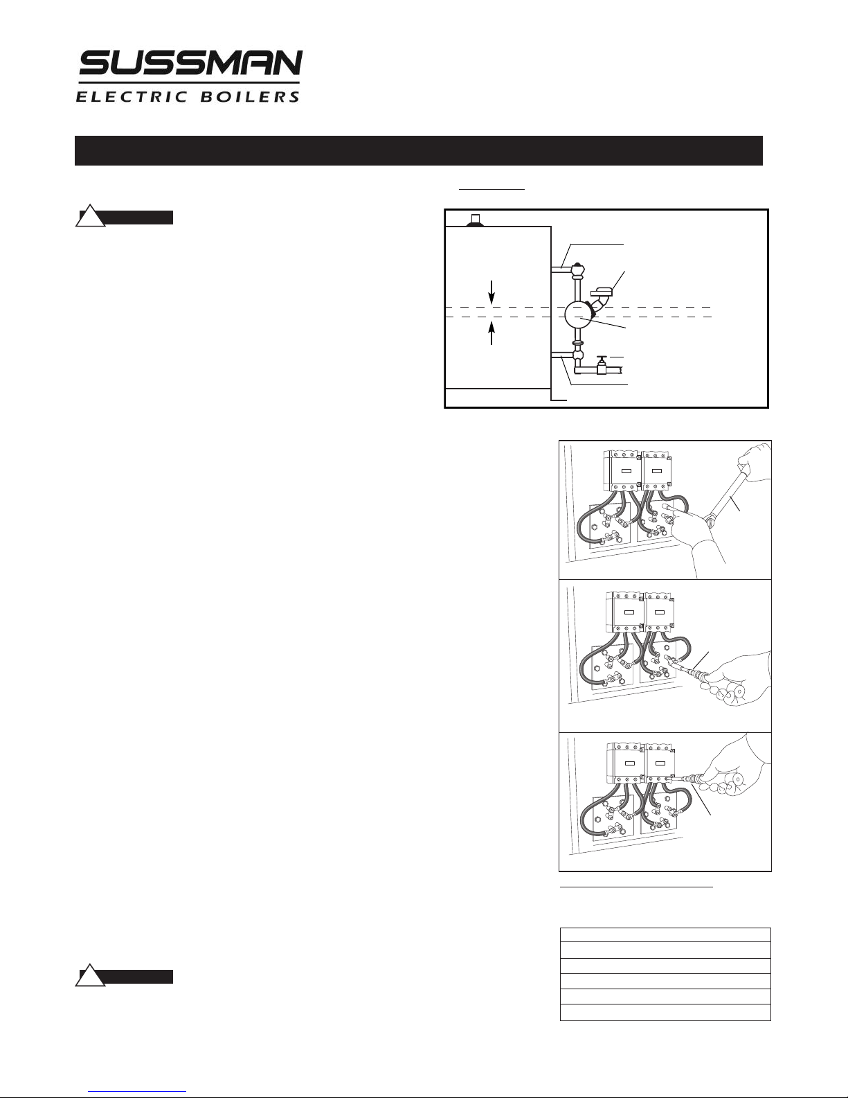
Use only new element flange bolts. Tighten all (6) element flange bolts to a torque value
of 22 lb-ft each (see illustration).
Connect all wires to the terminals. Tighten all element terminals to a torque value of
20 lb-in each (see illustration). Make sure all wires are clean and bright to assure good
electrical contact.
Check that the wires are correctly connected to the contactor terminals and are tightened
to a torque value of 45 lb-in. (see illustration). Make sure all wires are clean and bright to
assure good electrical contact.
Open water valve to allow water supply to reach boiler feed mechanism.
As boiler automatically refills, observe the new flange assembly for possible leaks. If water
is noticed, the bolts must be re-tightened. Before doing this, turn the boiler off at the
main fuse safety switch.
When boiler reaches working pressure, check flange assembly again for leaks.
CAUTIO N
Before Installing your new elements be sure the
Boiler with
McDonnell Miller
11⁄2”
Note the wire connections to facilitate re-assembly (see wiring schematic).
Follow maintenance instructions provided with the boiler.
1”Steam EqualizingPipe
Pumpand LowWater Control
Normal BoilerWater Line
Cut-Off Level isArrowMark
Blowdown Valve
1”Water Equalizing Pipe
Torque Values:
Torque
Wrench
Element Flange Bolts: 22 lb-ft
Torque
Wrench
Element Terminals: 20 lb-in
Torque
Wrench
Contactor Terminals: see Torque chart
For I llustrat ive Purposes Only.
Power wiri ng show n in appr oxi mate
factory- ins talled l ocation
TORQUE VALUES
Element Flange Bolts 22 lb-ft
Element Terminals 20 lb-in
Contactor Terminals 50 amp 25 lb-in
60 amp 45 lb-in
75 amp 75 lb-in
22
Page 23

Installation, Operation & Maintenance Manual
Water Quality Information for Carbon Steel Boilers
For optimum results, the feedwater supply should be tested prior to initial start-up. If the
mineral content exceeds the following recommended limits, various external treatment
processes (water softener, reverse osmosis, etc.) may be used to correct the problem.
NOTE:
An analysis of the on-site boiler feedwater must be made by a
recognized and reliable water treatment company to ascertain the existing
condition and treatment required.
RECOMMENDED FEEDWATER QUALITY
HARDNESS, ppm 8 – 85 (~0.5 – 5 gpg)
P-ALKALINITY, ppm 85 – 410 (~5 – 24 gpg)
T-ALKALINITY, ppm 200 – 500 (~7 – 0 gpg)
pH (strength of alkalinity) 8.0 – 11.4
SPECIFIC RESISTIVITY ~50k Ω cm (50,000 ohm-centimeter)
Blow down the boiler on at least a once-a-day basis. If boiler water or feed-water are
outside the above limits, a more frequent blowdown is required.
Water quality can affect efficiency or result in boiler damage if neglected. Boiler feedwater
contains impurities in solution and suspension. These impurities concentrate in the boiler
since the steam generated is essentially pure. The concentration of these impurities
increases as more feedwater is introduced into the boiler and steam is produced. If the
suspended solids are allowed to concentrate beyond certain limits, a deposit or “scale”
will form on the boiler’s internal surfaces. This deposit can interfere with proper boiler
operation and cause boiler failure.
The concentration of these impurities is generally controlled by the feedwater quality and
by blowdown. Blowdown refers to removing a portion of the boiler water with high solids
concentration and replacing it with make-up water of a lower concentration.
23
Page 24

A Division of Sussman-Automatic Corporation
43-20 34th Street, Long Island City, NY 11101 • (718) 937-4500
1-800-238-3535 • Fax: (718) 937-4676 • email: [email protected]
www.sussmanboilers.com
M A D E I N U S A
PUR 101137 4.13
 Loading...