

Sussman ES12-18, ES135-180, ES24-72, HU40-55, ES85-100 Installation, Operation And Maintenance Manual
...
ES & HU Installation, Operation
a nd Maintenance Manual
A Division of Sussman-Automatic Corporation
43-20 34th Street, Long Island City, NY 11101 • (718) 937-4500
1-800-238-3535 • Fax: (718) 937-4676 • email: seb@sussmancorp.com
www.sussmanboilers.com
PUR 101137
REV
5.18
Installation, Operation & Maintenance Manual
U S A
Designed, Engine ered
and Assembled in th e
Model No. _____________________________________
Boiler Serial No. _______________________________
National Board No. ___________________________
Safety Valve Set Pressure _______________ PSIG
Power Circuit Voltage _______________________
Control Circuit Voltage ______________________
Amps __________ Phase _________ HZ __________
Steam Outlet Valve Size _____________ NPT
Products covered by this manual:
_________________________________________________________________________________
KW Max Design Work
Series Range Steam Rate* BHP Pressure Pressure
_________________________________________________________________________________
ES, HU 12-180 36-542 lbs/hr 1.2-18.4 0-100 psig 85 psig
_________________________________________________________________________________
*Steam Rate: Steam at 212˚ F with 50˚ F feed water
ES and HU boilers are of Carbon Steel construction.
See page 23 for Water Quality Information.
TABLE OF CONTENTS
Dimensional Information and
Component Identification . . . . . . . . . . . . . . . . . 3
Dimensional & Clearing Specifications . . . . . . . . . 4
Wiring Diagram. . . . . . . . . . . . . . . . . . . . . . . . . . . . 5
Installation . . . . . . . . . . . . . . . . . . . . . . . . . . . . . . . 6
Piping. . . . . . . . . . . . . . . . . . . . . . . . . . . . . . . . . . 6
Wiring . . . . . . . . . . . . . . . . . . . . . . . . . . . . . . . . . 7
Pre-Operation Check. . . . . . . . . . . . . . . . . . . . . . . . 8
Setting Pressure Controls . . . . . . . . . . . . . . . . . . . . 9
Operation. . . . . . . . . . . . . . . . . . . . . . . . . . . . . . . . 10
Blowdown. . . . . . . . . . . . . . . . . . . . . . . . . . . . . 10-11
Digital Timer Operation Instructions . . . . . . . . . . 12
Timing Switch . . . . . . . . . . . . . . . . . . . . . . . . . . . . 13
Maintenance . . . . . . . . . . . . . . . . . . . . . . . . . . . . . 13
Standard Equipment
Auxiliary Low Water Cut Off . . . . . . . . . . . . . . . . 14
Line Pressure Water Feed System . . . . . . . . . . . . . 14
Optional Equipment
High Pressure Water Feed System. . . . . . . . . . . . . 14
Condensate Return System. . . . . . . . . . . . . . . . . . 14
Vacuum Breaker Systems . . . . . . . . . . . . . . . . . . . 15
Automatic Blowdown System. . . . . . . . . . . . . . . . 15
Control Voltage Stepdown Transformer . . . . . . . . 15
Blowdown Separators . . . . . . . . . . . . . . . . . . . . . 15
Multistage Load Progressive Sequencers . . . . . . . . 15
Condensate Return Systems . . . . . . . . . . . . . . . . . 16
Blowdown Separator Tanks . . . . . . . . . . . . . . . . . 17
Specification Charts. . . . . . . . . . . . . . . . . . . . . . . . 18
Sizing . . . . . . . . . . . . . . . . . . . . . . . . . . . . . . . . . . . 19
Gauge Glass Installation . . . . . . . . . . . . . . . . . 20-21
Element Replacement . . . . . . . . . . . . . . . . . . . . . . 22
Water Quality Information. . . . . . . . . . . . . . . . . . 23
IMPORTANT NOTE:
As you follow these instructions, you will notice warning and caution symbols. This blocked information is important for the safe and efficient
installation and operation of electric boilers. These are two types of potential hazards that may occur during this installation and operation:
WAR N I N G
!
may cause serious injury or death if precautions
are not followed.
states a hazard which
CA U T I ON
!
minor injury or product damage may occur if you
do not follow instructions.
signals a situation where
2
IMPORTANT NOTE:
This highlights information that is especially
relevant to a problem-free installation.
Installation, Operation & Maintenance Manual
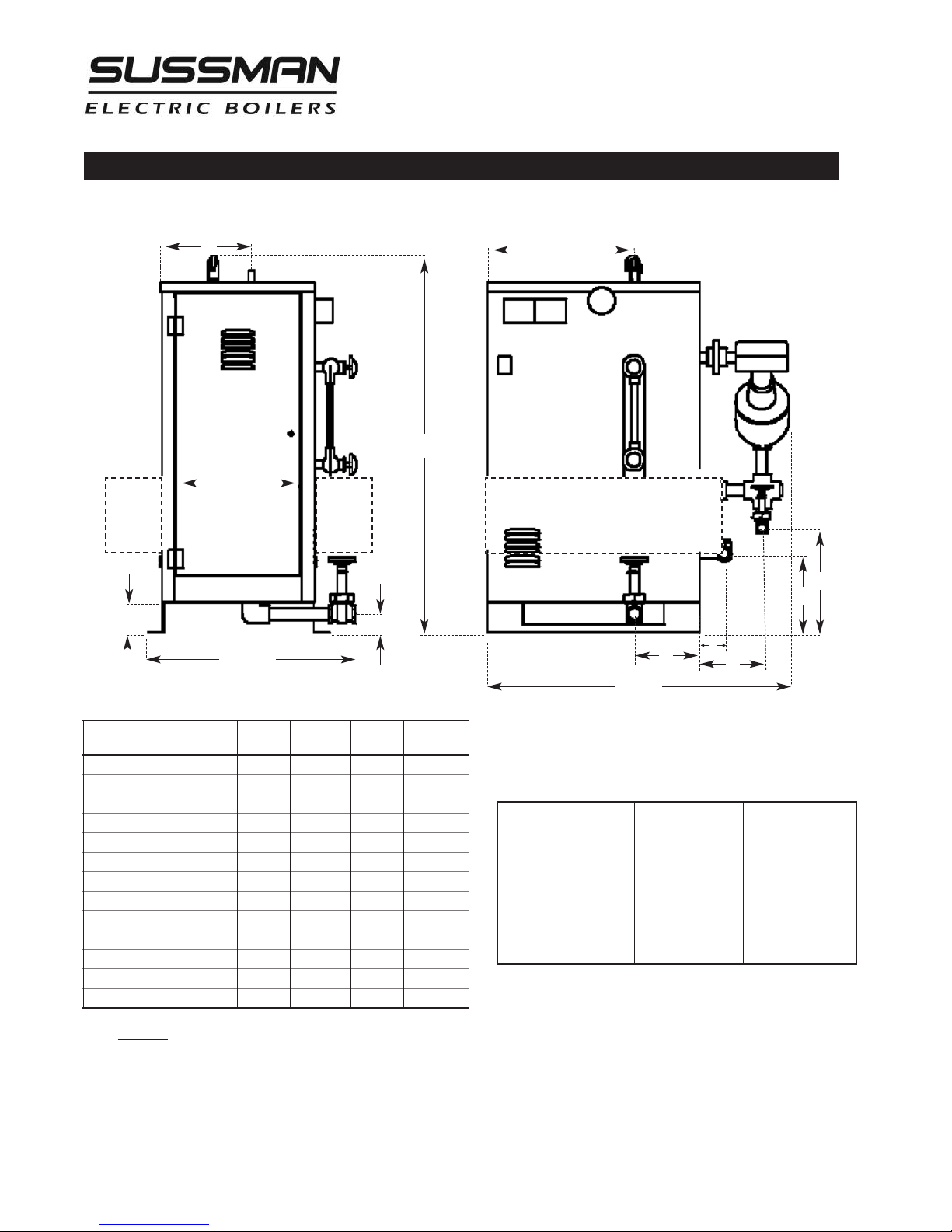
Dimensional Information & Component Identification
Models: ES, HU
A
B
Height
M
C
E
J
Width
F
G
K
D
Length
SYMBOL ITEM HU40-55 HU75-205 HU310 HU410-550
Height Overall Height 36" 46" 61" 61"
Length Overall Length 28" 33" 34" 36"
Width Overall Width 22" 22" 25"* 27"**
A Steam Outlet 6-1/4" 10" 8-1/4" 9"
B Steam Outlet 10-1/4" 17" 17-1/4" 18-1/4"
C M/M Drain Valve 5" 12" 17" 16-3/4"
D M/M Drain Valve 6-1/2" 6" 6-1/4" 6-1/4"
E Check Valve 14" 9" 17" 16-3/4"
F PV Drain Valve 2-3/4" 2-1/4" 2-3/4" 2-3/4"
G PV Drain Valve 6-1/4" 9-1/2" 7-3/4" 9-1/4"
J Clearance 3-3/4" 3-1/2" 4" 4"
K Check Valve 2-1/2" 2-3/4" 3" 3"
M Door Width 8-3/4" 14" 12-3/4" 14-3/4"
Allow minimum 36 inches clearance in front of doors for servicing of heating elements.
Recommended clearance: 24 inches other sides of boiler for servicing.
* ES100 Width shown is for 480 volts with one front mount fuse box, 208/240 volt that includes a front and back mounted fuse box is 30" wide
** ES135 -180 Width shown is for 480 volts with one front mount fuse box, 208/240 volt that includes a front and back mounted fuse box is 32" wide
All 480 volt ES100-180 include a front mounted box for fuses (shown as dotted lines)
All 208 and 240 Volt ES100-180 include a front and back mounted box for fuses (shown as dotted lines)
ES72 208 Volt includes a front mounted fuse box, overall width increases to 24"
ES12-18 ES24-72 ES85-100 ES135-180
MODEL 100 PSIG 15 PSIG 100 PSIG 15 PSIG
ES12-18, HU40-55
ES24-36, HU75-105 1”NPT 1”NPT
Steam Outlet Safety Valve Outlet
1
⁄
2
”
NPT
1
”
⁄
2
NPT
1
NPT
”
⁄
2
1
NPT
”
⁄
2
ES48, HU140 1”NPT 1”NPT 1” NPT
ES60-72, HU175-205 1”NPT 1”NPT 1” NPT 1” NPT
1
ES85-100, HU310 1
NPT 3”NPT 1”NPT 1
”
⁄
2
ES135-180, HU410-550 2”NPT 3”NPT 1”NPT 1
Water inlets for all ES & HU boilers are 1/2" NPT
Drains for all ES and HU boilers are 1" NPT
3
NPT
”
⁄
4
3
NPT
”
⁄
4
3
NPT
”
⁄
4
1
NPT
”
⁄
4
1
NPT
”
⁄
2
3
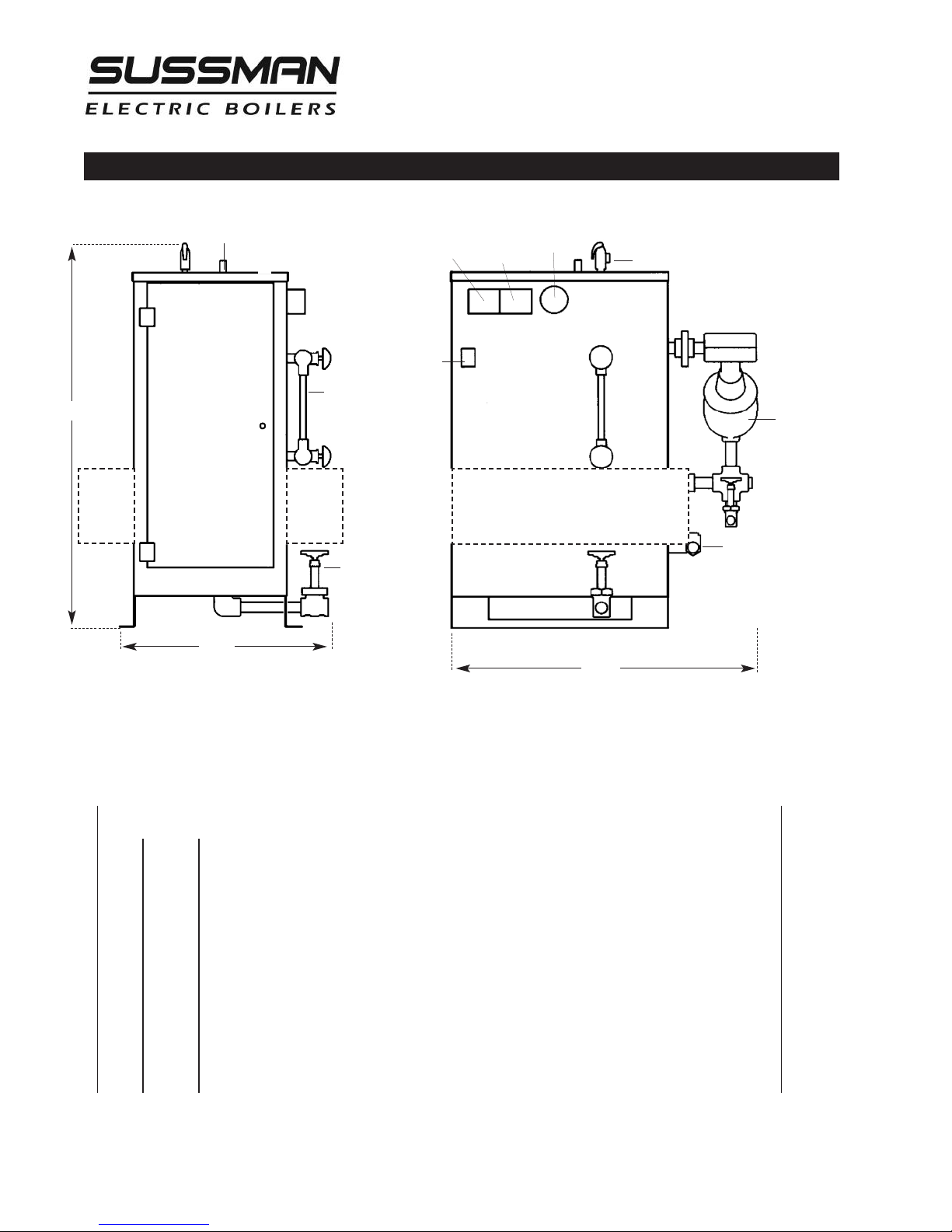
Installation, Operation & Maintenance Manual
Dimensional & Clearance Specifications
Height
perating
Steam Outlet
A
Gauge Glass
Assembly
D
Drain Valve
Width
O
P
C
On/Off
Switch
ressure
ontrol
EL
High Limit
Pressure
Control
ressure
P
auge
G
Safety Valve
Liquid Level
Control
ER
Water Feed Inlet
F
Length
Left Side Elevation Front Elevation
Allow 24" all around for servicing, 36” in front of doors, minimum.
__________________________________________________
Clearance from combustible surfaces
__________________________________________________
A
_________________________________________________________________________
B
_________________________________________________________________________
D
_________________________________________________________________________
EL
_________________________________________________________________________
ER
_________________________________________________________________________
F
_________________________________________________________________________
G-
_________________________________________________________________________
All 480 volt ES100 - 180 include a front mounted box for fuses (shown as dotted lines)
All 208 and 240 Volt ES100 - 180 include a front and back mounted box for fuses (shown as dotted lines)
ES72 208 Volt includes a front mounted fuse box.
1" Clearance above top of boiler
A Clearance from Front of boiler. Prefix "C" to numeral indicates acceptability for
closet or alcove installations; prefix acceptability for alcove installations but not
for closet installations.
1" Clearance from back of boiler.
1" Clearance from left side of boiler.
16" Clearance from right side of boiler.
C Indicates type of flooring: "NC" for non-combustible; "C" for combustible.
Total minimum free area in square inches of close ventilating openings.
4
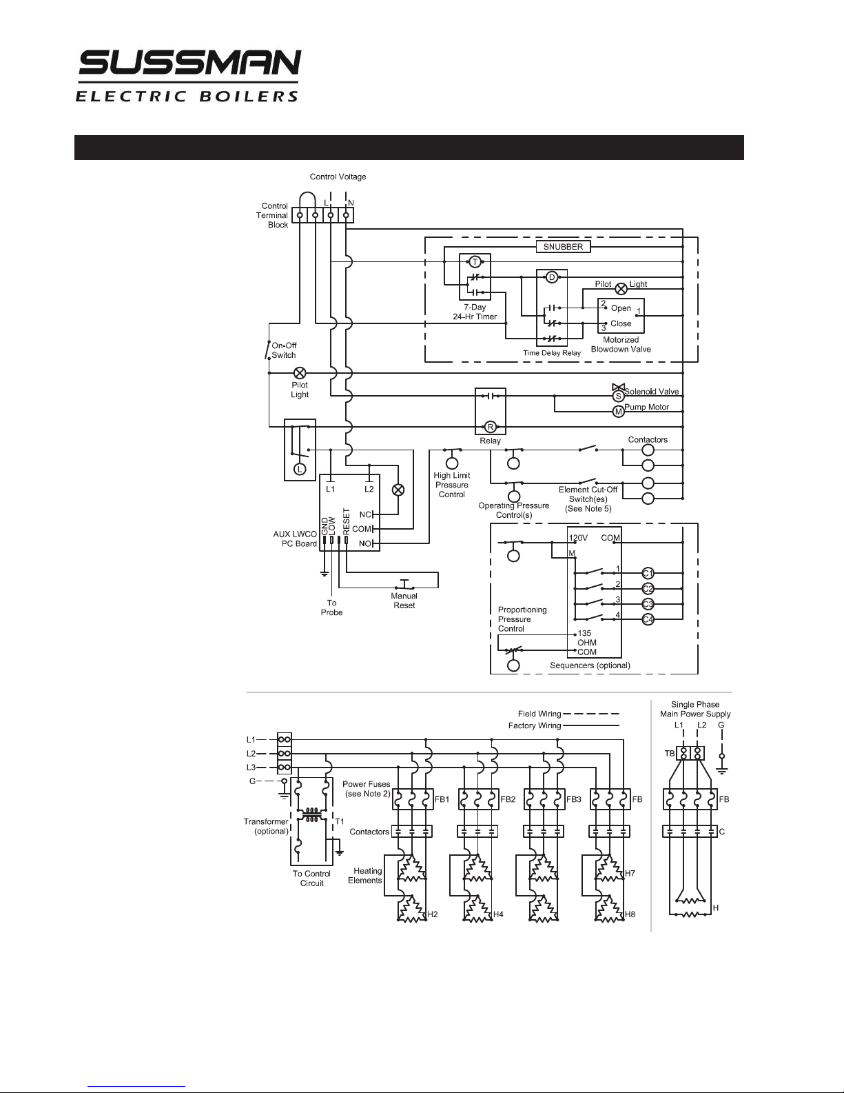
P1
C1
C2
C
3
C
4
P2
P2
P3
P3
(
See Note 6)
C1 C2 C3 C4
H1 H3 H5
H6
ES/SSB/CU 81600
Automatic Blowdown
System (optional)
Wiring Diagram
Power Circuit and
Control Circuit use
different voltage
Installation, Operation & Maintenance Manual
Three Phase Main Power Supply
NOTES:
1. Power Terminal Block only on boilers with two or more contactors.
2. On boilers with only one power contactor, connect power voltage to line side of contactor.
3. Power Fuses only on boilers rated 120 amperes and larger.
4. See Parts List for contactor and heating element information.
5. Element cut-off switches and second operating pressure control on ES/SSB 100-180 without sequencer
6. Refer to boiler nameplate for control and main power voltage
5

Installation
Installation, Operation & Maintenance Manual
REFER TO NATIONAL AND ALL APPLICABLE LOCAL
CODES FOR SPECIFIC INSTALLATION REQUIREMENTS.
1. The boiler should be mounted on a solid, level foundation.
2. The boiler should be located with suitable clearances, refer
to page 3 and Code requirements.
NOTE:
Allow a minimum of 36 inches clearance in front of
doors for servicing of heating elements. Recommended clearance: 24 inches other sides of boiler for servicing.
Piping
ALL PIPING SHOULD BE INSTALLED BY A
QUALIFIED LICENSED PLUMBER IN ACCORDANCE WITH NATIONAL AND LOCAL CODES.
1. When water feed is other than pump type the water
supply pressure must be 10 psig greater than boiler
operating pressure to assure water supply maintains
proper water level in the boiler. Insufficient water levels
can result in improper boiler operation. (Keep feed
water valves open at all times during normal operation.)
2. Connect steam line with a valve to boiler steam outlet
3. Do not install boiler in any location where water
could freeze.
4. Do not install boiler outdoors.
5. Do not install boiler near flammable or corrosive
materials.
6. Do not install boiler in a location where leakage
from the boiler tank or piping can damage to
adjacent areas or to lower floors of the structure.
Provide a floor drain and properly sloped floor
from the boiler towards the drain or install a suitably plumbed drain pan under the boiler.
NOTE:
ice higher than the maximum boiler pressure should be
plumbed on the steam outlet line; failure to do so can cause
heating element breakdown. See page 3 for steam outlet
valve size.
4. Provide for boiler drain connection, a daily blowdown is
5. Safety valve shall be plumbed according to local code.
NOTE:
sized less than the outlet size of the safety valve.
For best performance, a valve rated for steam serv-
required. A "Blowdown Separator Tank" may be
necessary, check with local code.
The safety valve shall not be plumbed with a line
6
Installation, Operation & Maintenance Manual
Wiring
ALL ELECTRICAL WIRING MUST BE PERFORMED BY A QUALIFIED ELECTRICIAN
IN ACCORDANCE WITH NATIONAL AND LOCAL ELECTRICAL CODES.
CA U T I ON
!
being supplied to the boiler matches the power voltage and
phase of the boiler. Connecting incorrect power supply can
damage boiler components or cause improper boiler operation. If the boiler power requirements do not match the
power to be supplied to the boiler the boiler must be
returned to the factory for conversion. Boilers cannot be
field converted.
ALL BOILERS ARE PRE-WIRED AND TESTED
PRIOR TO SHIPMENT.
1. Ground boiler according to National Electric Code
requirements to avoid shock.
2. Power wiring to boiler should be in accordance with
National and Local Electrical Code requirements following wiring diagram supplied. Use proper size wire. Wire
size is specified adjacent to field wiring terminals. This
label states the wire size [AWG or MCM], minimum
temperature rating (90 C) and conductor material
(copper only). Deviation from these requirements
may result in improper or unsafe boiler operation.
3. A disconnect switch employing circuit breakers or fuses
should be installed between the main power source and
the boiler. This disconnect switch should be located near
the boiler and clearly marked for easy access and identification should the boiler need to be turned off due to
an emergency.
Assure that the power voltage and phase
4. Boiler control circuit is 120 Volt*. Unless boiler has an
optional step down transformer, a separate 120 Volt
power feed wiring is required to be connected to the
control circuit terminal block. A 15 Amp circuit is
required for all boilers. If a 3/4 HP feed water motor
and pump assembly is connected to the boiler, then a
20 Amp circuit is required.
5. If a separate control circuit is used, it should be
connected to the control circuit terminal block.
6. Remote mounted water feed systems (i.e. condensate
return, motor and pump) should be connected to the
junction box provided on the outside of the boiler
jacket.
7. With main power off, make sure all wiring terminations are tight to avoid arcing, carbonizing or overheating of contacts.
CA U T I ON
!
damage due to water line connections. An industrial
type lightning/surge protector should be installed according to the manufacturer's recommendation at the service
entrance. Consult your contractor or electrical dealer.
WAR N I N G
!
cation of wiring system voids the warranty and may lead
to dangerous operating conditions.
Boilers are susceptible to lightning
Substitution of components or modifi-
7

Installation, Operation & Maintenance Manual
Pre-Operation Check (All Boilers)
LWCO/PUMP CONTROL OPERATION AND TESTING
1. All valves for incoming water supply are to be fully opened.
Main disconnect switch is to be in the "on" position. Boiler main
switch is to be in the "on" position. Since boiler will be empty
the pump or solenoid will be energized allowing the boiler to
fill with water. Control will automatically fill boiler to proper
operating water level and the pump/solenoid will be deenergized. Contactors will then energize, applying voltage to
the heating elements.
2. Pump switch operation – at this point water should be visible
approximately half way up the sight glass. Slowly open the drain
valve located at the bottom of the boiler. Water level in the
sight glass will begin to drop, allowing the low water cut
off/pump control to energize the feed water system. Close valve
for proper operation.
3. Low water cutout switch performance – open the drain valve
completely. Maintain this condition until water level falls within
the gauge glass enough to cause the low water cutout switch to
de-energize the heating elements. All of the contactors will be
in a de-energized or open state at this time. Close the drain
valve, water feed system will automatically refill the boiler and
the contactors will re-energize.
Pressure Controls, Operation and Testing
Boilers equipped with an auxiliary low water cut-off
control with a manual re-set button (required as
mandatory equipment is some states): once the correct
operating water level has been reached, it will be
necessary to depress the reset button in order for the
contactors to re-energize.
NOTE:
down system:
• For test 1 - the blowdown time clock must be in the
• For test 2 and 3 - in order for the drain valve to open
For boilers equipped with an automatic blow-
“run” mode before the boiler will automatically fill.
the blowdown clock must be in the “off” mode.
(See blowdown time clock insert) The automatic
blowdown indicator light will be on when the valve
is open. This light will remain on for the duration of
the blowdown cycle (a few seconds). It may be necessary to cycle the time clock from the “run” to
“off” mode several times.
NOTE:
All boilers are provided with one high limit pres-
sure control and at least one operating pressure control.
1. The high limit pressure control is equipped with a manual
reset feature. There is no subtractive differential scale with
this type of control
2. All pressure controls are equipped with an adjusting screw,
allowing for setting of desired operational and high limit
pressures. To reduce pressure setting, turn adjusting screw
in direction that allows indicator to point to a lower
pressure setting on the scale. To increase pressure setting
turn adjusting screw in direction that allows indicator to
point to a higher pressure on the scale
NOTE:
10% above the desired normal operating pressure (15 psig
boilers should be set to 13 psig)
3. Operating pressure controls, except low pressure (15 psig)
4. Operating pressure control check: Close steam outlet valve
It is recommended that the high limit control be set
types have a separate differential scale. Differential
indicates pressure below the main operating maximum
pressure, the pressure control will re-set. The differential set
point is adjusted in the same manner by turning the
adjusting screw in the desired direction to increase or
decrease the differential pressure value.
[supplied by customer] and adjust operating pressure
control to 20 psig (10 psig for low pressure boilers) and
the differential to 10 psig (Note: Low pressure boilers do
not have a differential setting). Set the high limit
pressure control to 30 psig (13 psig for low pressure
boilers). Switch boiler on to allow steam pressure to
build-up. Pressure gauge reading will increase and the
operating pressure control will de-energize the
contactor(s) when the pressure gauge indicates 20 psig
(10 psig for low pressure boilers). Open steam outlet
valve to bleed off pressure. When the pressure gauge
reading decreases below 10 psig (differential) (3 psig for
low pressure boilers) the operating pressure control will
re-energize the contactor(s).
5. High limit pressure control check: FOR TEST PURPOSES
ONLY! Set the high limit pressure control 10 psig (5 psig
for low pressure boilers) lower than the operating
pressure control. Close the steam outlet valve and switch
the boiler on to allow boiler to build pressure. When the
pressure gauge indicates the pressure at which the high
limit pressure control is set, the high limit pressure
control re-set button will pop-up and the control will deenergize the contactor(s). Open the steam outlet valve to
bleed off pressure. The contactor(s) should not reenergize on pressure drop. The contactor(s) should only
re-energize when the pressure has dropped and the high
limit pressure control reset button is depressed.
8
 Loading...