

Sussman ES 24A, ES30A, ES36A, HP30A Installation, Operation And Maintenance Manual
ES 24A Electric
Steam Generator
Installation, Operation and Maintenance Manual
Model No. ___________________________ Power Circuit Voltage ___________________
Boiler Serial No. __________________ Control Circuit Voltage __________________
National Board No ____________________ Amps ________ Phase ________ Cy ________
IMPORTANT:
This data file contains the National Board Registration Certificate
approving your generator. It must be kept near the generator at all times.
Products Covered by this Manual
KW Design Max. Work
Model Range Steam Rate BHP Pressure Pressure*
__________________________________________________________________________________________
24A 24 73 lbs./hr 2.44 100 PSIG 90 PSIG
__________________________________________________________________________________________
*Line water pressure must be a minimum of 10 PSIG higher than generator operating pressure or you will require high pressure water feed
w/motor and pump.
Installation
CAUTION
!
NOTE:
Standard minimum suggested clearance is 21 inches.
Reference heating element clearance requirements for particular boiler to allow for removal of elements.
Refer to National and all applicable Local Codes for specific installation requirements.
1.
The boiler should be mounted on a solid level foundation.
2.
All piping should be installed by a licensed plumber.
3.
When any type water feed other than a pump feed is used, the existing water supply pressure must be 10 PSIG
greater than boiler operating pressure to assure water supply maintains proper water level in boiler. Lack of
water can result in improper boiler operation. Keep feed water valves open at all times during normal operation.
4.
Connect steam line with customer supplied outlet valve to boiler steam outlet.
5.
During normal operation, keep drain valve closed.
6.
If pump and boiler are plumbed within 30 ft (pipe length), a minimum of two check valves are required on boiler to avoid damage to pump.
NOTE:
THE SAFETY VALVE SHALL NOT BE PLUMBED WITH A DRAIN
LINE SIZED LESS THAN THE OUTLET SIZE OF THE SAFETY VALVE.
A Division of Sussman-Automatic Corporation
43-20 34th Street, Long Island City, NY 11101•(718) 937-4500•1-800 238- 3535
Fax: (718) 937-4676
•
www.sussmanboilers.com•Email: seb@sussmancorp.com
PN 101167 5/12
ES 24A Electric Steam Generator Installation, Operation and Maintenance Manual
1
/4 NPT Water Inlet
Connection
Electric Service Entrance
I
K
J
E
O
F
H
M
L
P
G
7
5
6B
6A
6A
1
2
3
4
5
A
B
C
8
10
9
12
11
Hi-Limit
Control
D
Operating
Control
_____________________________________________________________________________
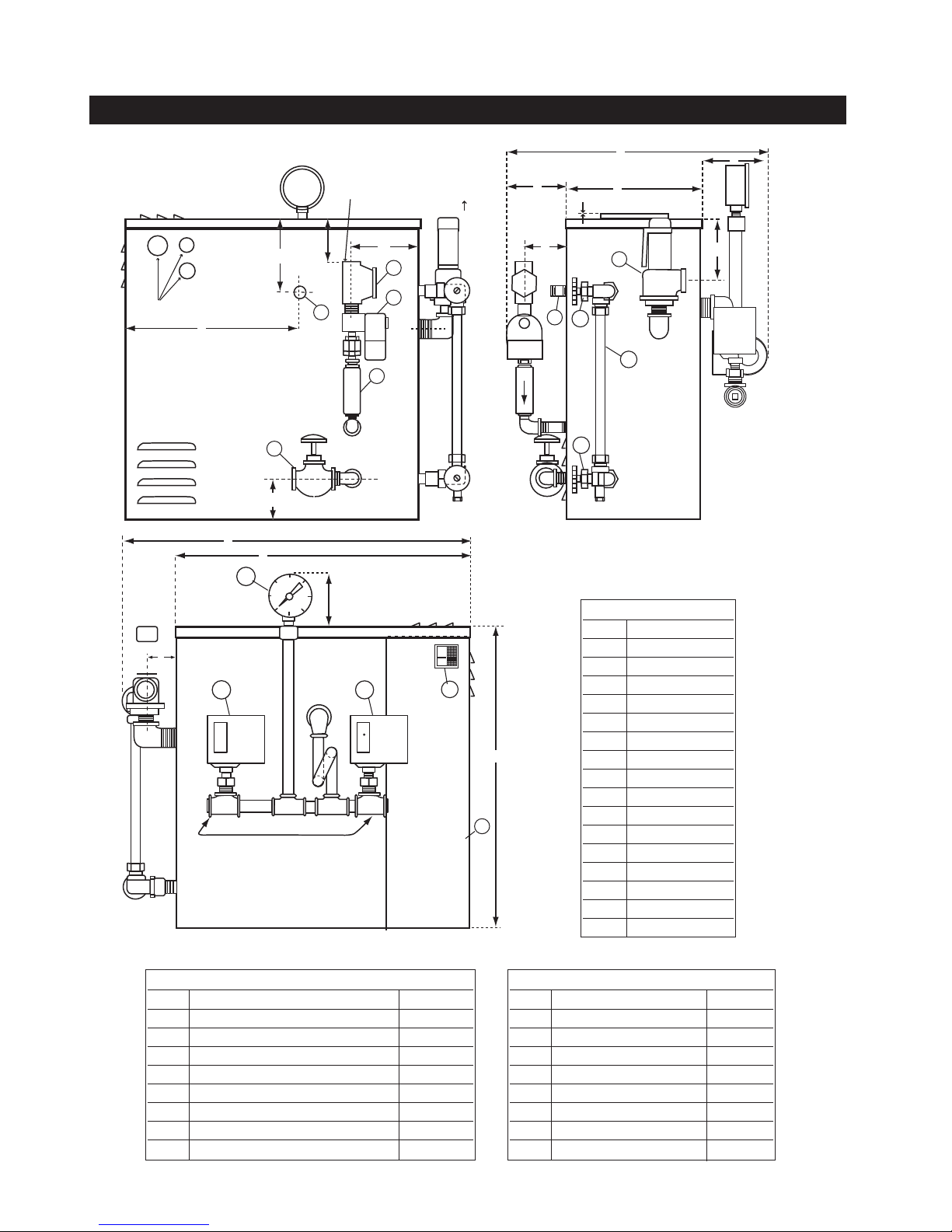
Component Identification Dimensional Information
Dimensional Table
Item Models 24A
A25
B22
C17
D1
E 1611⁄16
F4
G2
H2
I3
J9
K2
L10
M4
N2
O8
P2
3
6
⁄1
1
(
)
⁄8
REF
13
(
)
⁄16
REF
3
⁄4
1
⁄16
15
⁄16
1
⁄2
1
⁄2
1
⁄8
1
⁄4
5
⁄16
5
⁄16
5
⁄8
3
⁄4
1
⁄2
Dimensional Table Model 24A
Item Description
11⁄4 NPT Strainer 93806
21⁄4 NPT 120V 60HZ Solenoid,1⁄4 OBIF. 99042
33⁄8 NPT Check Valve 99162
41⁄2 NPT Drain Valve 99178B
51⁄2 NPT Steam Outlet Nipple 100380
6A Gauge Glass Valve Set 99173C
6B Gauge Glass Tube 99074-1
1
7
⁄2 NPT 100PSIG S.Valve 99136
Dimensional Table Model 24A
Item Description
81⁄4 NPT Pressure Gauge 99197
9 Hi-Limit Pressure Control 99066
10 operating Pressur Control 99966
11 Access Panel -----12 Main On-Off Switch 92830
13 Probe Isolator 100378
14 Probe Spark Plug 90229
15 Probe 5 inch 99807F
2
ES 24A Electric Steam Generator Installation, Operation and Maintenance Manual
_____________________________________________________________________________
Wiring
CAUTION
!
Electric Code requirements to avoid shock. Use proper sized
wire. Power wiring to boiler should be in accordance with
Local and N.E.C. requirements following wiring diagram
supplied. Wire size specified adjacent to field wiring terminal block(s). Use 90˚ C copper wire only.
Purchaser should use a disconnect switch employing circuit breakers or fuses between the main power source and the boiler.
CAUTION
!
age because of plumbing water lines. Industrial type lightning/surge protectors should be installed according to the
manufacturer's recommendation at your service entrance.
Consult your contractor or electrical dealer.
1.
The unit is pre-wired and tested. Connect control circuit volt-
age at the control circuit terminal block.
2.
With the main power off, make sure that all wiring termina-
tions are tight to avoid arcing, carbonizing and/or overheating
of contacts.
Ground boiler according to National
Boilers are susceptible to lightning dam-
WARNING
!
modification of wiring systems voids the warranty and
may lead to dangerous operating conditions.
3.
Instructions for water feed control system (i.e. motor and
pump or solenoid feed).
a.
Check the voltage of the motor or solenoid before
making electrical connection.
WARNING
!
wired to the junction box provided.
c.
Motors rated greater than 1/3HP or are not 120VAC sin-
gle phase require the use of suitable motor starter.
d.
Amperage/Wire Size – For correct sizing refer to the label
on the boiler located next to the field wiring termi nals. This
label states the wire size (AWG or MCM), minimum temperature rating (90˚C) and conductor material (copper only).
Deviation from this information may result in improper or
unsafe boiler operation.
Substitution of components or
b.
The water feed circuit should be
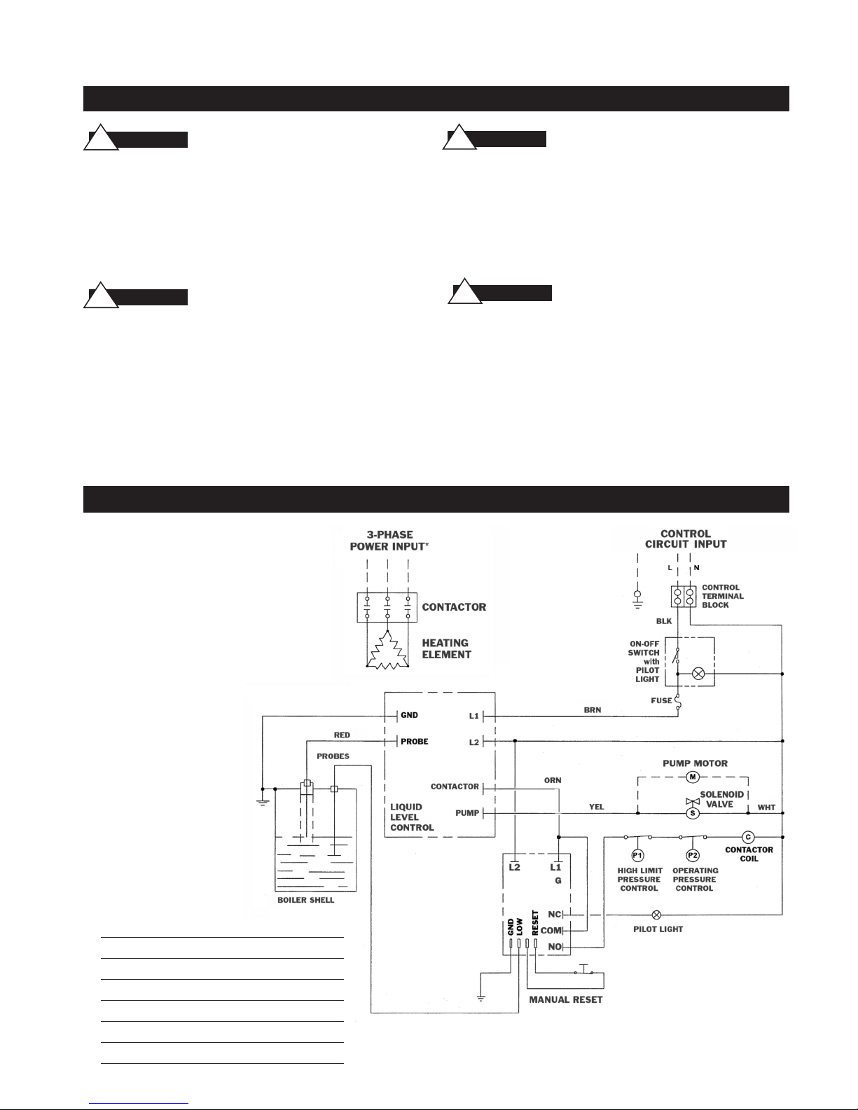
Wiring Diagram Control Circuit ES-24A–PRI Electric Boilers
Typical Wiring Diagram 24A
Factory Wiring ___________
Field Wiring __ __ __ __ __
Note: *See Boiler Nameplate for
Input requirements
Electrical Parts List
39243B Heating Element 24kw 208v 3Ph
39243C Heating Element 24kw 240v 3Ph
39243F Heating Element 24kw 480v 3Ph
102206-1 Contactor 75 amp 3 pole 120v Coil
100412A Liquid Level Control Board 120v
90241MRT Auxiliary LWCO Board 120v
3
 Loading...