

Page 1

ES 24A Electric
Steam Generator
Installation, Operation and Maintenance Manual
Model No. ___________________________ Power Circuit Voltage ___________________
Boiler Serial No. __________________ Control Circuit Voltage __________________
National Board No ____________________ Amps ________ Phase ________ Cy ________
IMPORTANT:
This data file contains the National Board Registration Certificate
approving your generator. It must be kept near the generator at all times.
Products Covered by this Manual
KW Design Max. Work
Model Range Steam Rate BHP Pressure Pressure*
__________________________________________________________________________________________
24A 24 73 lbs./hr 2.44 100 PSIG 90 PSIG
__________________________________________________________________________________________
*Line water pressure must be a minimum of 10 PSIG higher than generator operating pressure or you will require high pressure water feed
w/motor and pump.
Installation
CAUTION
!
NOTE:
Standard minimum suggested clearance is 21 inches.
Reference heating element clearance requirements for particular boiler to allow for removal of elements.
Refer to National and all applicable Local Codes for specific installation requirements.
1.
The boiler should be mounted on a solid level foundation.
2.
All piping should be installed by a licensed plumber.
3.
When any type water feed other than a pump feed is used, the existing water supply pressure must be 10 PSIG
greater than boiler operating pressure to assure water supply maintains proper water level in boiler. Lack of
water can result in improper boiler operation. Keep feed water valves open at all times during normal operation.
4.
Connect steam line with customer supplied outlet valve to boiler steam outlet.
5.
During normal operation, keep drain valve closed.
6.
If pump and boiler are plumbed within 30 ft (pipe length), a minimum of two check valves are required on boiler to avoid damage to pump.
NOTE:
THE SAFETY VALVE SHALL NOT BE PLUMBED WITH A DRAIN
LINE SIZED LESS THAN THE OUTLET SIZE OF THE SAFETY VALVE.
A Division of Sussman-Automatic Corporation
43-20 34th Street, Long Island City, NY 11101•(718) 937-4500•1-800 238- 3535
Fax: (718) 937-4676
•
www.sussmanboilers.com•Email: [email protected]
PN 101167 5/12
Page 2
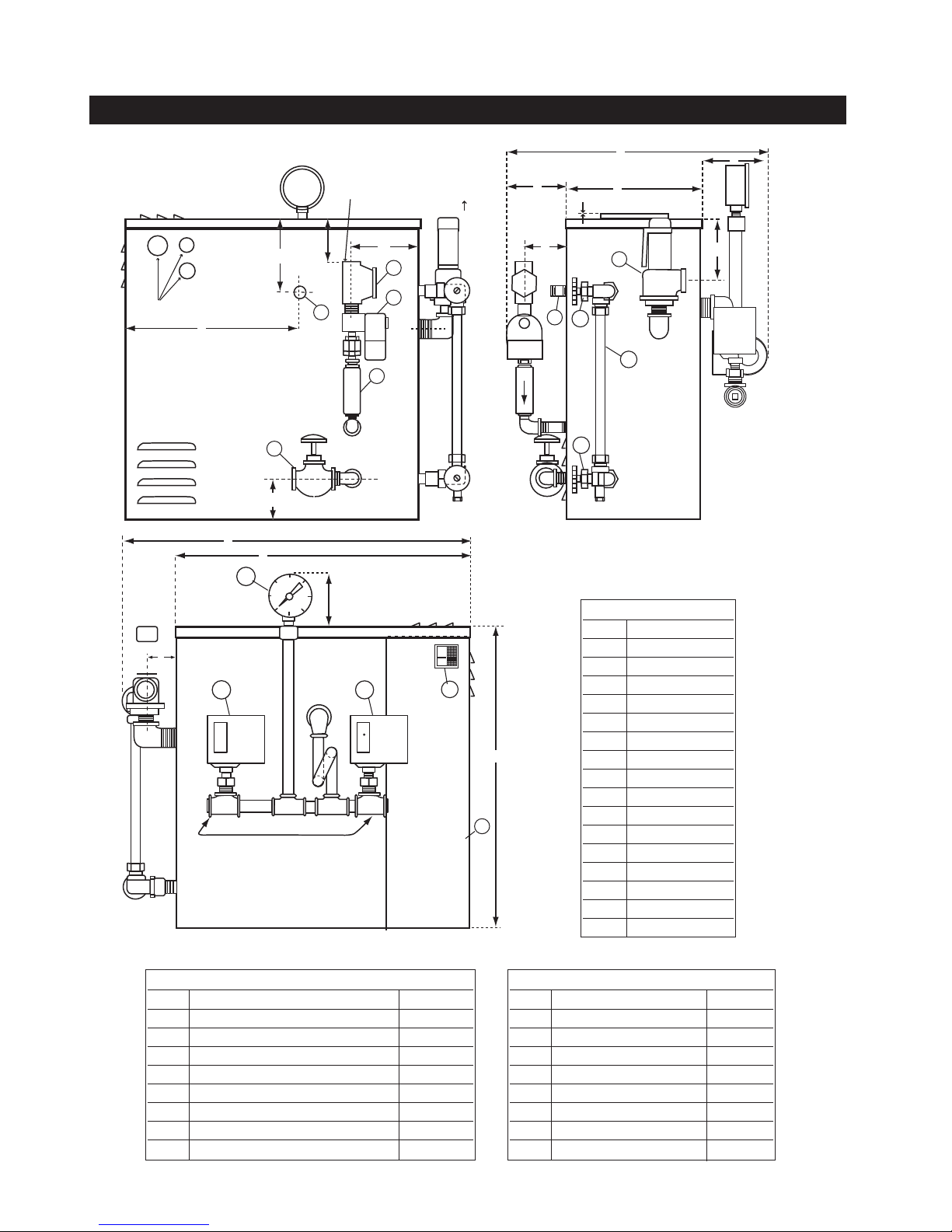
ES 24A Electric Steam Generator Installation, Operation and Maintenance Manual
1
/4 NPT Water Inlet
Connection
Electric Service Entrance
I
K
J
E
O
F
H
M
L
P
G
7
5
6B
6A
6A
1
2
3
4
5
A
B
C
8
10
9
12
11
Hi-Limit
Control
D
Operating
Control
_____________________________________________________________________________
Component Identification Dimensional Information
Dimensional Table
Item Models 24A
A25
B22
C17
D1
E 1611⁄16
F4
G2
H2
I3
J9
K2
L10
M4
N2
O8
P2
3
6
⁄1
1
(
)
⁄8
REF
13
(
)
⁄16
REF
3
⁄4
1
⁄16
15
⁄16
1
⁄2
1
⁄2
1
⁄8
1
⁄4
5
⁄16
5
⁄16
5
⁄8
3
⁄4
1
⁄2
Dimensional Table Model 24A
Item Description
11⁄4 NPT Strainer 93806
21⁄4 NPT 120V 60HZ Solenoid,1⁄4 OBIF. 99042
33⁄8 NPT Check Valve 99162
41⁄2 NPT Drain Valve 99178B
51⁄2 NPT Steam Outlet Nipple 100380
6A Gauge Glass Valve Set 99173C
6B Gauge Glass Tube 99074-1
1
7
⁄2 NPT 100PSIG S.Valve 99136
Dimensional Table Model 24A
Item Description
81⁄4 NPT Pressure Gauge 99197
9 Hi-Limit Pressure Control 99066
10 operating Pressur Control 99966
11 Access Panel -----12 Main On-Off Switch 92830
13 Probe Isolator 100378
14 Probe Spark Plug 90229
15 Probe 5 inch 99807F
2
Page 3
ES 24A Electric Steam Generator Installation, Operation and Maintenance Manual
_____________________________________________________________________________
Wiring
CAUTION
!
Electric Code requirements to avoid shock. Use proper sized
wire. Power wiring to boiler should be in accordance with
Local and N.E.C. requirements following wiring diagram
supplied. Wire size specified adjacent to field wiring terminal block(s). Use 90˚ C copper wire only.
Purchaser should use a disconnect switch employing circuit breakers or fuses between the main power source and the boiler.
CAUTION
!
age because of plumbing water lines. Industrial type lightning/surge protectors should be installed according to the
manufacturer's recommendation at your service entrance.
Consult your contractor or electrical dealer.
1.
The unit is pre-wired and tested. Connect control circuit volt-
age at the control circuit terminal block.
2.
With the main power off, make sure that all wiring termina-
tions are tight to avoid arcing, carbonizing and/or overheating
of contacts.
Ground boiler according to National
Boilers are susceptible to lightning dam-
WARNING
!
modification of wiring systems voids the warranty and
may lead to dangerous operating conditions.
3.
Instructions for water feed control system (i.e. motor and
pump or solenoid feed).
a.
Check the voltage of the motor or solenoid before
making electrical connection.
WARNING
!
wired to the junction box provided.
c.
Motors rated greater than 1/3HP or are not 120VAC sin-
gle phase require the use of suitable motor starter.
d.
Amperage/Wire Size – For correct sizing refer to the label
on the boiler located next to the field wiring termi nals. This
label states the wire size (AWG or MCM), minimum temperature rating (90˚C) and conductor material (copper only).
Deviation from this information may result in improper or
unsafe boiler operation.
Substitution of components or
b.
The water feed circuit should be
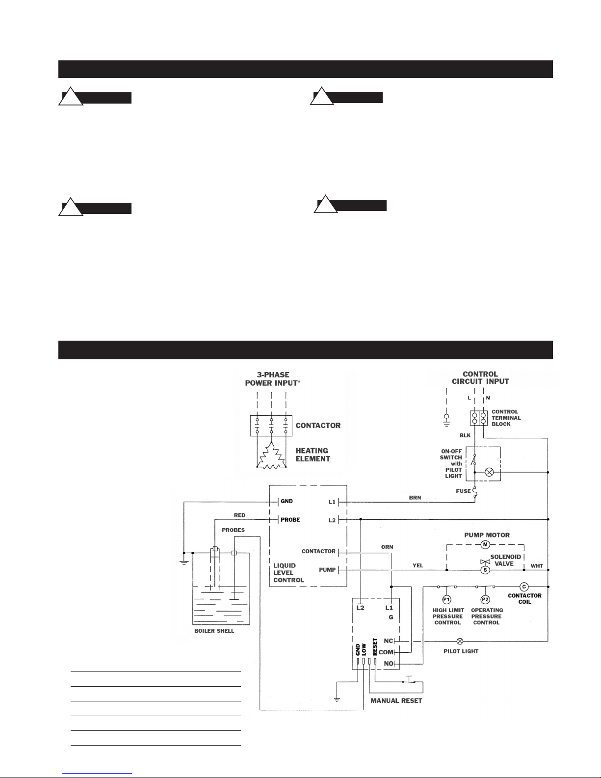
Wiring Diagram Control Circuit ES-24A–PRI Electric Boilers
Typical Wiring Diagram 24A
Factory Wiring ___________
Field Wiring __ __ __ __ __
Note: *See Boiler Nameplate for
Input requirements
Electrical Parts List
39243B Heating Element 24kw 208v 3Ph
39243C Heating Element 24kw 240v 3Ph
39243F Heating Element 24kw 480v 3Ph
102206-1 Contactor 75 amp 3 pole 120v Coil
100412A Liquid Level Control Board 120v
90241MRT Auxiliary LWCO Board 120v
3
Page 4

ES 24A Electric Steam Generator Installation, Operation and Maintenance Manual
_____________________________________________________________________________
Pre-Operation Check - All Boilers
LWCO/PUMP CONTROL, OPERATION AND TESTING
1.
All valves for incoming water supply are to be fully opened. Main disconnect switch to be in "ON” position. Boiler switch to be in
"ON" position. Since boiler will be empty, pump (or solenoid) will be energized allowing boiler to fill with water. Control will allow for
automatic reaching of proper water level. Contactors will be energized, applying voltage to heating elements.
2.
Pump Switch Operation – At this point, water should be visible approximately halfway up sight glass. Slowly open drain valve located
at bottom of boiler. Water level will fall, allowing low water cutoff/pump control to energize feed water system. Close drain valve for
proper operation.
3.
Low Water Cut-Out Switch Performance. Open drain valve completely. Maintain this condition until water level falls within gauge glass
enough to cause low water cut-out switch to de-energize heating elements. Contactor will be in the de-energized state at this time.
Close the drain valve. For automatic resetting type low water cut-out switches, feed system will return water level to normal. Boiler is
now qualified for proper low water cut-out and normal liquid-level operating conditions.
PRESSURE CONTROLS OPERATION AND TESTING
NOTE: ALL ES STEAM BOILERS ARE PROVIDED WITH ONE HI-LIMIT PRESSURE CONTROL AND ONE
OPERATING PRESSURE CONTROL.
1.
All pressure controls are equipped with a screw allowing for setting of the desired operational and hi-limit pressures.
To reduce pressure setting, rotate screw in direction which allows indicator to point to a lower pressure setting.
NOTE: IT IS RECOMMENDED THAT THE HI-LIMIT CONTROL BE SET 1O PSIG ABOVE DESIRED NORMAL
OPERATION PRESSURE.
2.
A differential pressure can be obtained on all automatic re-setting operating pressure controls in the same manner as operating
pressure control is set. Differential indicated pressure below the main operating maximum pressure the pressure control will reset.
3.
Pressure Control Operating Check – Close steam outlet valve (by customer) and adjust operating pressure control to a low pressure
setting. Set hi-limit control at 10 PS1G above that setting. Switch boiler on to allow for steam pressure build-up. Pressure gauge
reading will build and the operating pressure control will shut off boiler at its pressure setting. Re-setting of operating pressure control
is accomplished by bleeding off pressure through steam outlet valve (by customer) and allowing pressure to drop below set point.
4.
Hi-limit Pressure Control Check – See item 3 above but, in doing so, assure for this test purpose only, that the operating control is
set above the pressure setting of the hi-limit control. The hi-limit trip will de-energize the contactors. Resetting of the hi-limit occurs
after bleeding steam to reduce pressure inside the boiler.
CAUTION
!
TO AVOID IMPROPER OR UNSAFE CONDITIONS, INSURE OPERATING PRESSURE CONTROL IS
RESET TO PROPER DESIRED BOILER OPERATING PRESSURE.
Operation
CAUTION
!
1.
Turn on water supply. Turn main switch on. Turn boiler switch to ON position. When water appears approximately halfway up the
gauge glass, the pump or solenoid feed will automatically shut off and the contactors will switch on.
2.
Operation of Low Water Cut-Off – The boiler is equipped with a probe type liquid level control which is coupled to an electronic
controller (pc board).
3.
The automatic reset operating pressure control has a visual pressure adjustment. The top screw of the control adjusts the scale in the
large indicator window. By turning the screw, the pressure setting can be adjusted. Selection of desirable pressure is very easily made.
Some pressure controls have an additional screw for adjustment of pressure differential (OFF/ON pressure operating range) which is
factory set at the maximum allowable rating.
4.
Close steam outlet valve. Boiler will build up to desired pressure and shut off automatically.
5.
High Pressure Control – This control will de-energize the boiler should pressure within the boiler exceed the set pressure.
6.
Slowly open steam outlet valve and use steam as needed.
7.
Boiler should be blowndown daily (see blowdown instructions on page 6).
ONLY WITH MAIN DISCONNECT “OFF”, TIGHTEN ALL ELECTRICAL CONNECTIONS BEFORE ENERGIZING
BOILER TO PREVENT ARCING, CARBONIZING OF CONTACTS AND/OR OVERHEATING.
4
Page 5

ES 24A Electric Steam Generator Installation, Operation and Maintenance Manual
_____________________________________________________________________________
Blowdown
Blowdown is an essential part of boiler operation. It is one of the best preventative maintenance steps you
an take. Make sure a blowdown schedule is established and followed regularly.
c
n hard water areas, blowdown is necessary at least once a day. In soft water areas, once a week. If there
I
is a particular problem which applies to your own local water condition other than mineral content, take
this into consideration in determining whichschedule is to be followed.
1.
At the end of the working day, while boiler is still operating, turn switch to the OFF position and close
water supply valve. De-energize wall mounted safety switch.
2.
It is preferable to connect the blowdown valve directly into a drainage system when allowed by local
codes. If this is done, the boiler can be discharged at operating pressure. Consult local plumbing codes
before doing so.
3.
If blowing-down into a receptacle, allow pressure to decrease to 15-20 PSIG before opening blowdown valve.
4.
When discharge is complete and boiler is drained:
1. Close the blowdown valve 3. Put boiler switch in the ON position
2. Open water supply valve; 4. Close wall mounted safety switch.
5.
When refilling is complete, turn off the boiler switch unless further operation is desirable.
6.
If you have been supplied with a Manual Reset Low Water Control as required in some states, the
reset button on the control must be pushed before boiler will begin developing pressure. (Do not push
reset until boiler has filled with water.)
Maintenance
CAUTION
!
WORKING ON BOILER.
Sussman Electric Steam boilers are designed for years of trouble-free performance. To establish a good
preventative maintenance program, we suggest that the building maintenance person or engineer familiarize themselves with these simple rules.
1.
The sight glass should be checked daily to ensure that boiler has adequate water.
2.
A monthly inspection should be made of the internal wiring. All electrical connections should be
checked for tightness. A check for water leaks should also be made and any loose fittings immediately
tightened.
3.
Every four months, the low water cut-off and pump control should be checked to insure that it is functioning properly.
4.
Every four months, the probe and isolator should be checked for deposits and cleaned, if necessary.
This is accomplished by removing the inspection plate, removing the probe (with a standard socket
wrench) cleaning and replacing.
5.
Every four months, the heating elements should be removed. If scale has begun to form, the element
should be cleaned and the boiler should be drained and flushed.
NOTE: NEW BOLTS AND GASKET SHOULD BE USED WHEN RE-INSTALLING THE
ELEMENT TO ASSURE PROPER SEALING.
HAZARD OF ELECTRICAL SHOCK. DISCONNECT ALL POWER BEFORE
5
Page 6
ES 24A Electric Steam Generator Installation, Operation and Maintenance Manual
_____________________________________________________________________________
Element Replacement
READ INSTRUCTIONS COMPLETELY BEFORE STARTING WORK
AUTION
C
!
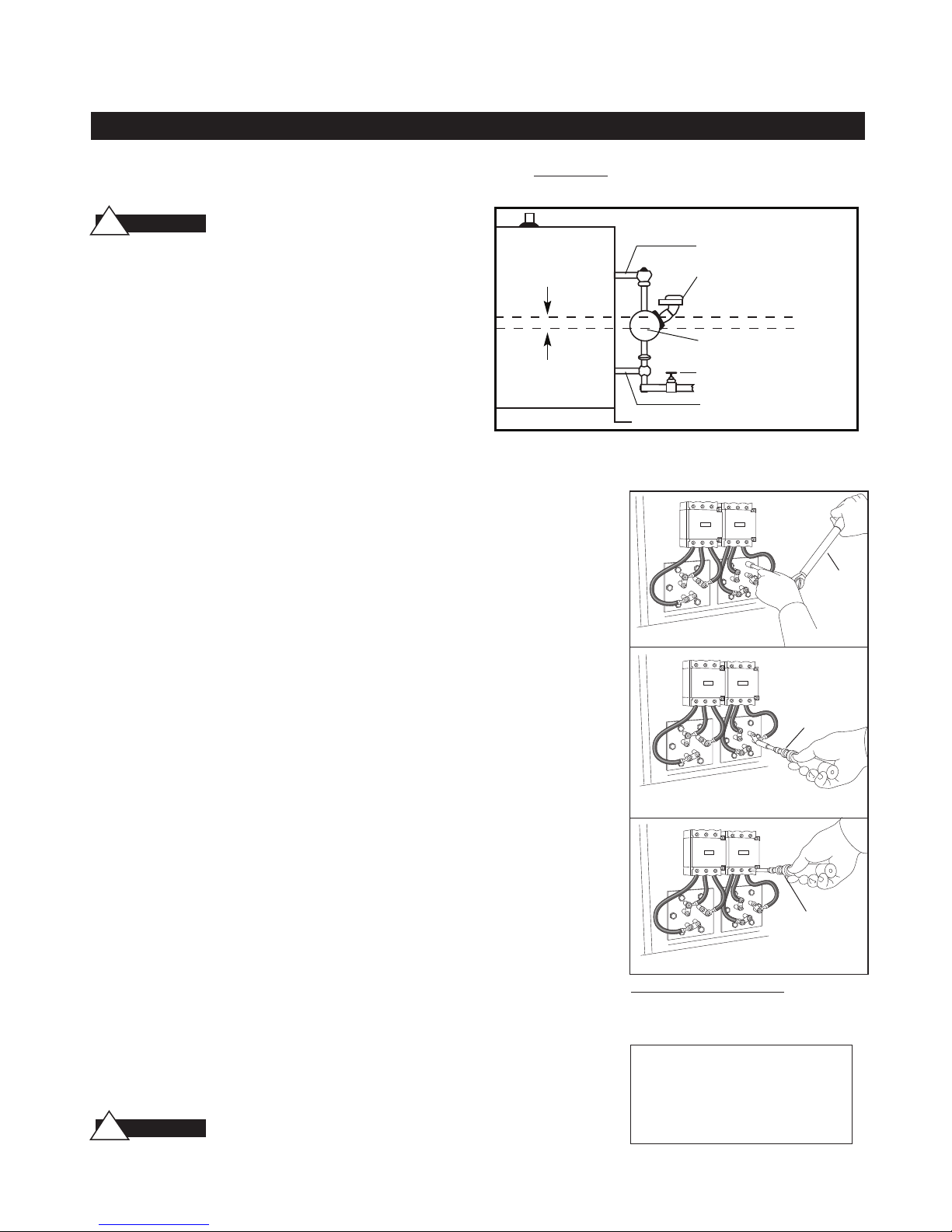
water cutoff (if supplied) is operating properly. The float chamber and
lower equalizer column of the MM control must be completely clear of
Before Installing your new elements be sure the
McDonnell Miller low water cut-off and aux. low
Boiler with
McDonnell Miller
sludge or other foreign matter. Failure to do this may cause the immediate burn-out of the new elements. If the unit is probe equipped,
check condition of the probes and isolator.
All elements are thoroughly checked before shipment The manufacturer cannot be responsible for burn-outs caused by a faulty low water
cut-off.
11⁄2”
The lower equalizer column can best be examined by breaking the
unions on either side and then visually and manually examining the
piping with your finger or probes to see if it is clear and clean.
1.
Disconnect boiler from electric power supply at main safety switch or
fuse panel. Then turn boiler switch to “OFF" position.
2.
Close water supply valve on incoming water supply line.
Drain boiler completely of water.
3.
Open boiler door to access heating element.
4.
Disconnect wire (electric) leads connecting element to main power system of boiler.
Again, note wire connections to facilitate re-assembly. Proceed to remove
and discard (6) bolts from flange.
IMPORTANT:
Note the wire connections to facilitate re-assembly (see wiring schematic).
Remove and discard six (5/16"-18) bolts from flange. Do not reuse these bolts.
5.
Thoroughly clean boiler flange of all foreign material. Be certain no part of old gasket
remains on flange.
6.
Apply "Slic-Tite" Gasket Compound (or equal) to both surfaces of new gasket supplied
with replacement element. Proceed to install element flange assembly with gasket
between boiler flange and element flange. In doing this, be careful to align flange holes
so element wire connection terminals on element assembly are in line with previously
disconnected wire leads to facilitate easy connections.
NOTE:
7.
Observe markings on element flange. Install element marking “TOP” on top.
Use only new element flange bolts. Tighten all (6) element flange bolts to a torque value
of 22 lb-ft each (see illustration).
8.
Connect all wires to the terminals. Tighten all element terminals to a torque value of
20 lb-in each (see illustration). Make sure all wires are clean and bright to assure good
electrical contact.
9.
Check that the wires are correctly connected to the contactor terminals and are tight-
ened to a torque value of 45 lb-in. (see illustration). Make sure all wires are clean and
bright to assure good electrical contact.
10.
Open water valve to allow water supply to reach boiler feed mechanism.
11.
As boiler automatically refills, observe the new flange assembly for possible leaks.
If water is noticed, the bolts must be re-tightened. Before doing this, turn the boiler
off at the main fuse safety switch.
12.
When boiler reaches working pressure, check flange assembly again for leaks.
CAUTION
!
Follow maintenance instructions provided with the boiler.
1” Steam Equalizing Pipe
Pump and Low Water Control
Normal Boiler Water Line
Cut-Off Level is Arrow Mark
Blowdown Valve
1” Water Equalizing Pipe
Torque Values:
Torque
Wrench
Element Flange Bolts: 22 lb-ft
Torque
Wrench
Element Terminals: 20 lb-in
Torque
Wrench
Contactor Terminals: see Torque chart
For Illustrative Purposes Only.
Power wiring shown in approximate
factory-installed location
TORQUE VALUES
________________________________________
Element Flange Bolts 22 lb-ft
________________________________________
Element Terminals 20 lb-in
________________________________________
Contactor Terminals 45 lb-in
6
Page 7
ES 24A Electric Steam Generator Installation, Operation and Maintenance Manual
_____________________________________________________________________________
Gauge Glass Installation
IMPORTANT NOTE:
efore performing installation or maintenance. Safety glasses
b
Read all warnings and instructions
and gloves should be worn at all times when working with or
examining water gauge glass and connections. Pressure in generator to be at zero before proceeding. Improper installation or
maintenance of gauge glass and connections can cause immediate or delayed breakage resulting in bodily injury and/or property damage.
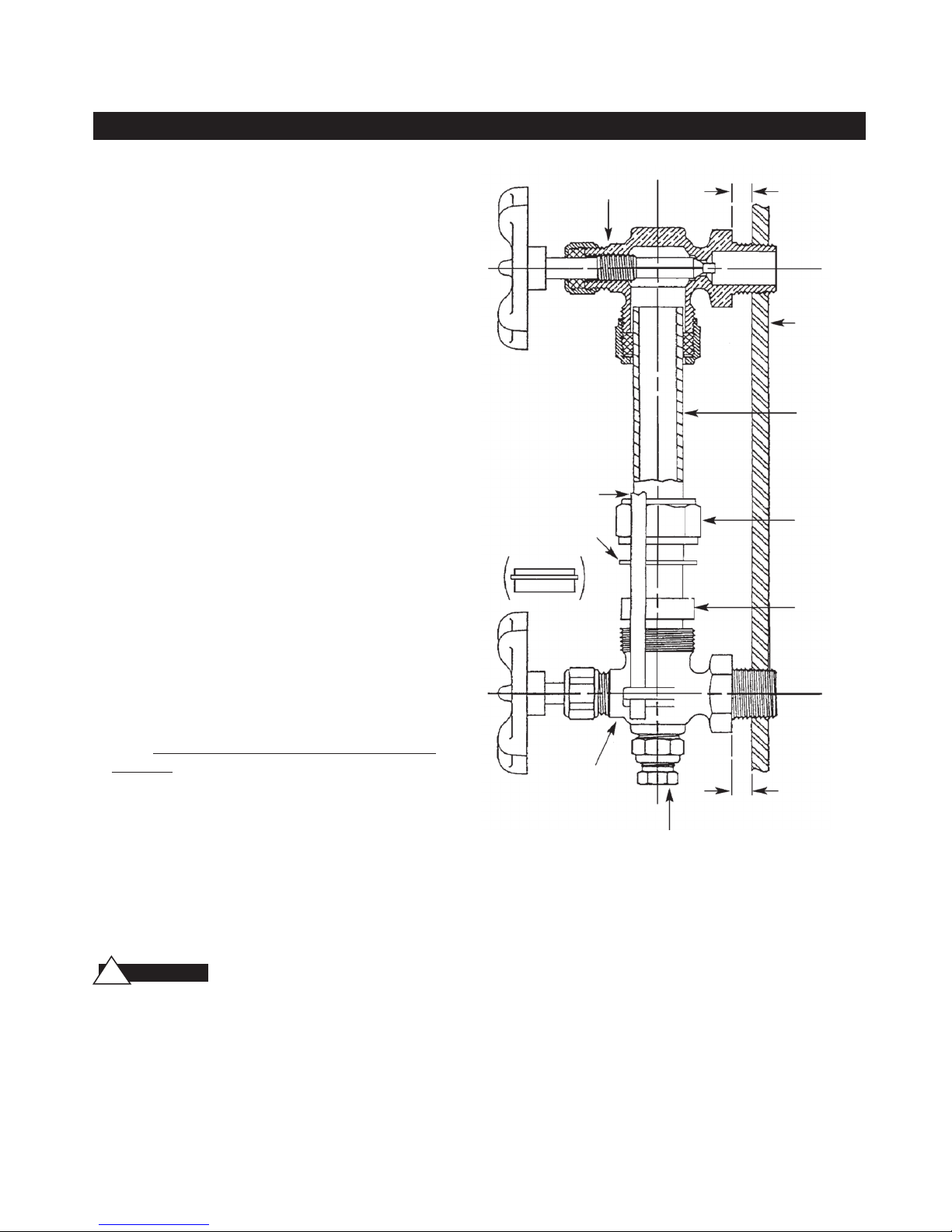
1.
Apply Teflon tape or pipe dope to pipe threads. Install top
gauge fitting (fitting without a drain valve) into the uppermost tapping. Wrench tighten the fitting until it is snug and
the glass outlet is pointing at five o'clock (about 1/8 turn
from its final downward vertical position).
2.
Install the bottom gauge fitting (the fitting with a drain
valve) until it is snug and the glass outlet is pointing directly
upward. Verify top and bottom fittings are threaded into the
tappings the same number of turns (distance A= distance B).
3.
Remove glass packing nut, friction washer (or packing
gland, depending upon the model), and glass packing from
the fittings, and place them, in the same order, on to both
ends of the gauge glass. Push both packings about an inch
up the gauge glass.
4.
Gently insert one end of the glass into the top gauge fitting.
Keeping the glass inside the top fitting, gently rotate the top
gauge fitting clockwise until vertically aligned with the bottom gauge, then insert glass into bottom fitting until glass
bottoms out on the shoulder inside the bottom fitting.
5.
Carefully raise glass about 1/16" and slide lower glass packing down until the glass packing contacts the lower gauge
fitting. DO NOT allow the glass to remain in contact with
any metal!
6.
Carefully slide upper glass packing up as far as possible.
7.
Hand tighten both glass packing nuts, then tighten 1/2 turn
more by wrench. Tighten only enough to prevent leakage.
DO NOT OVER TIGHTEN! If any leakage should occur,
tighten lightly, a quarter turn at a time, checking for leakage
after each turn.
op Gauge
T
Fitting
Guard Rod
Friction Washer
(or Packing Gland)
Bottom
Gauge
Fitting
A
Vessel Wall
Gauge Glass
Glass Packing
Nut
Glass Packing
B
Drain Valve
IMPORTANT NOTE:
WARNING
!
Read all warnings and instructions before performing installation or maintenance.
Safety glasses and gloves should be worn at all times when
working with or examining water gauge glass and connections.
Pressure in generator to be at zero before proceeding.
Improper installation or maintenance of gauge glass and connections can cause
immediate or delayed breakage resulting in bodily injury and/or property damage.
7
Page 8

ES 24A Electric Steam Generator Installation, Operation and Maintenance Manual
_____________________________________________________________________________
Water Quality Information for Carbon Steel Boilers
For optimum results, the feedwater supply should be tested prior to initial start-up. If the
mineral content exceeds the following recommended limits, various external treatment processes (water softener, reverse osmosis, etc.) may be used to correct the problem.
NOTE:
An analysis of the on-site boiler feedwater must be made by a
recognized and reliable water treatment company to ascertain the existing
condition and treatment required.
RECOMMENDED FEEDWATER QUALITY
HARDNESS, ppm 8 – 85 (~0.5 – 5 gpg)
P-ALKALINITY, ppm 85 – 410 (~5 – 24 gpg)
T-ALKALINITY, ppm 200 – 500 (~7 – 0 gpg)
pH (strength of alkalinity) 8.0 – 11.4
SPECIFIC RESISTIVITY ~50k Ω cm (50,000 ohm-centimeter)
Blow down the boiler on at least a once-a-day basis. If boiler water or feed-water are
outside the above limits, a more frequent blowdown is required.
RECOMMENDED LIMITS WITHIN A BOILER
TOTAL DISSOLVED SOLIDS, ppm 3500
TOTAL ALKALINITY, ppm 850
SUSPENDED SOLIDS, ppm 300
SILICA (Si02), ppm 125
SULFITE (SO3), ppm 25–50
PHOSPHATE, ppm 30–60
P-ALKALINITY AS CaCO3, ppm 900
IRON, ppm 2
Water quality can affect efficiency or result in boiler damage if neglected. Boiler feedwater contains impurities in solution and suspension. These impurities concentrate in the boiler since the steam generated is
essentially pure. The concentration of these impurities increases as more feedwater is introduced into the
boiler and steam is produced. If the suspended solids are allowed to concentrate beyond certain limits, a
deposit or “scale” will form on the boiler’s internal surfaces. This deposit can interfere with proper boiler
operation and cause boiler failure.
The concentration of these impurities is generally controlled by the feedwater quality and by blowdown.
Blowdown refers to removing a portion of the boiler water with high solids concentration and replacing it
with make-up water of a lower concentration.
A Division of Sussman-Automatic Corporation
43-20 34th Street, Long Island City, NY 11101•718-937-4500•1-800 238- 3535
Fax: 718-937-4676
•
www.sussmanboilers.com•Email: [email protected]
8
PN 101167 5/12
 Loading...