

Page 1

USER MANUAL
Mask Aligners
MA6 / MA8
Manual Mask Aligner
Rev05/ 07-06
www.suss.com
Page 2

Page 3

Contents
MA6 / MA8 - Contents - Rev.05 07-06
I
I
Contents
Preface .................................................................................................................................................. a
1. Operation of the Machine ................................................................................. 1
1.1 Definitions .......................................................................................................................... 3
1.1.1 How to Use this Manual ........................................................................................ 3
1.1.2 Key LED's ............................................................................................................. 3
1.1.3 Coordinate Systems .............................................................................................. 4
1.1.4 Components of the Exposure Optics ..................................................................... 5
1.1.4.1 Exposure Lamp ....................................................................................... 6
1.1.4.2 Ellipsoidal Mirror ...................................................................................... 6
1.1.4.3 Cold Light Mirror ..................................................................................... 6
1.1.4.4 Fly’s Eye Lens ......................................................................................... 6
1.1.4.5 Condenser Lens ...................................................................................... 6
1.1.4.6 Filters ...................................................................................................... 6
1.1.4.7 Integrator Block ...................................................................................... 6
1.1.4.8 Field Lens ............................................................................................... 6
1.1.4.9 Turning Mirror ......................................................................................... 6
1.1.4.10 Front Lens ............................................................................................... 6
1.1.4.11 Cleaning of Optical Parts ......................................................................... 7
1.1.4.12 Deep UV Exposure .................................................................................. 7
1.2 Controls and Indicators ...................................................................................................... 8
1.2.1 Alignment Stage Controls ...................................................................................... 8
1.2.2 Front Panel Controls .............................................................................................. 9
1.2.3 Keyboard Controls .............................................................................................. 11
1.2.4 TSA-Microscope Controls ................................................................................... 15
1.2.4.1 M 3xx Microscope ................................................................................ 16
1.2.4.2 Dual Video Microscope DVM 6/8 .......................................................... 18
1.2.5 Lamp House Controls ......................................................................................... 18
1.2.6 Joystick and Buttons ........................................................................................... 19
1.3 Operating Procedures ..................................................................................................... 20
1.3.1 Power on Procedure ........................................................................................... 20
1.3.2 First Mask Print Mode ......................................................................................... 20
1.3.3 Top Side Alignment ............................................................................................. 21
1.3.4 Bottom Side Alignment ........................................................................................ 23
1.3.5 Single Bottom Side Alignment ............................................................................. 24
1.4 Advanced Technology ..................................................................................................... 26
1.4.1 Exposure Programs ............................................................................................. 26
1.4.2 Multiple Exposure ................................................................................................ 27
1.4.3 Wedge Error Compensation ................................................................................ 27
1.4.4 Load Mask by Slide ............................................................................................. 27
1.5 Step by Step Machine Interactions .................................................................................. 29
1.5.1 Select Mask Loading Type .................................................................................. 29
1.5.2 SELECT PROGRAM for Exposure ....................................................................... 30
1.5.3 EDIT PARAMETER Menu .................................................................................... 31
1.5.4 Changing the TSA, BSA and Stage Alignment Speed .......................................... 32
1.5.5 EDIT PROGRAM Menu ........................................................................................ 33
1.5.6 Change Mask ...................................................................................................... 34
1.5.7 Load Wafer ......................................................................................................... 35
1.5.8 Load Mask by Slide ............................................................................................. 36
2. Maintenance ....................................................................................................39
2.1 General ............................................................................................................................. 39
Page 4

Contents
MA6 / MA8 - Contents - Rev.05 07-06
I
II
2.1.1 General Maintenance ............................................................................................ 39
2.1.2 Visual Checks ....................................................................................................... 39
2.1.3 Test Run ............................................................................................................... 39
2.1.4 Safety System Check ........................................................................................... 39
2.2 Preventive Maintenance for MA6/ MA8 ............................................................................. 39
2.2.1 Cleaning ............................................................................................................... 39
2.2.2 Lamp Service ....................................................................................................... 40
2.2.3 Greasing ............................................................................................................... 40
2.2.4 WEC-Check ......................................................................................................... 40
2.2.5 Recommended SUSS Service .............................................................................. 40
2.3 Measuring the Intensity/ Uniformity of the Exposure Light ................................................. 40
2.3.1 Power Supply Calibration ...................................................................................... 40
2.3.2 Alignment of Lamp in Ellipsoid Mirror .................................................................... 41
2.4 Replacement of the Exposure Lamp 1000 W .................................................................... 43
2.4.1 Replacement Procedure ....................................................................................... 43
2.4.2 Adjusting the Exposure Lamp ............................................................................... 43
2.4.3 N2-Control ........................................................................................................... 45
2.4.4 Exhaust Flow Control (in Lamp house Intake Tube) ............................................... 45
2.4.5 Use of Other Lamps ............................................................................................. 45
2.4.6 Lamp House 350W and 350W Lamp Replacement .............................................. 45
2.5 Replacement of the Microscope Lamp ............................................................................. 46
2.6 Cleaning of Optical Components ...................................................................................... 47
2.6.1 Cleaning Materials ................................................................................................ 48
2.6.2 Application Technique .......................................................................................... 48
2.6.3 Cleaning Procedure .............................................................................................. 48
2.6.4 Safe Clean-up after Use of Solvents ..................................................................... 50
2.6.5 Removal and Re-Insertion of Specific Optical Components .................................. 50
2..6.6 Conclusion ........................................................................................................... 51
2.7 Facts and Data for Maintenance and Service .................................................................... 51
2.7.1 Consumables ....................................................................................................... 51
2.7.2 Hazardous Materials and Solid Waste .................................................................. 52
2.7.3 Service Exchange of Heavy Subassemblies ......................................................... 52
2.7.4 Supplier’s Contact ................................................................................................ 52
3 Appendix ......................................................................................................... 53
3.1 Parameter Ranges and Default Settings ........................................................................... 53
3.2 List of Abbreviations ....................................................................................................... 55
3.3 Spare Parts Llist (Extract) ................................................................................................. 57
3.4 Lock-Out / Tag-Out Checklist .......................................................................................... 63
3.5 Schematics of the Pneumatic System .............................................................................. 65
3.6. Schematics of the Electronic System MA6/8 BA6/8........................................................... 82
3.7 Service Information .......................................................................................................... 84
3.7.1 Subassemblies: MA8; MA6; MA6/BA6; BA6; MA6/BA6-ISA; ............................... 84
3.7.2 Overview for Valves, Throttles, Sensors, etc. ....................................................... 85
3.8 International Chemical Safety Cards ................................................................................. 95
Page 5

Preface
MA6 / MA8 - Preface - Rev.05 07-06
a
Preface
The SUSS laboratory mask aligners are machines designed for photolithography applica-
tions in laboratories and for small-scale production. The MA6 and MA8 machines only differ
insignificantly in terms of operation.
Accordingly, the manuals for the mask aligners MA6 and MA8 have also been combined.
In this manual, minor differences are given special mention or are described by means of
specially identified pictures or sketches. Essentially, the differences relate to:
– machine dimensions, outline and weight
– travel path of the microscscope
– maximum size of the masks and substrates/wafers which are used
– changeover between mask aligner and bond aligner operation
(a detailed description is provided in BA6 Bond Aligner manual)
All of the tooling for the MA6 and MA8, e.g. chucks, mask holders and mask holder adapter
frames can be used on both mask aligners. Excepted from this are the BSA chucks for
BSA microscopes with split-field magnification. The BSA apertures are approx. 185mm
wide in a horizontal direction. This means that these chucks cannot be used on a standard
mask aligner with standard BSA microscopes.
Page 6

MA6 / MA8 - Preface - Rev.05 07-06
b
Page 7

Attention !
MA6 / MA8 - Attention ! - Rev.05 07-06
c
Attention !
It is strongly recommended to read this
User Manual before starting the Mask
Aligner the first time.
Page 8

MA6 / MA8 - Attention ! - Rev.05 07-06
d
Page 9
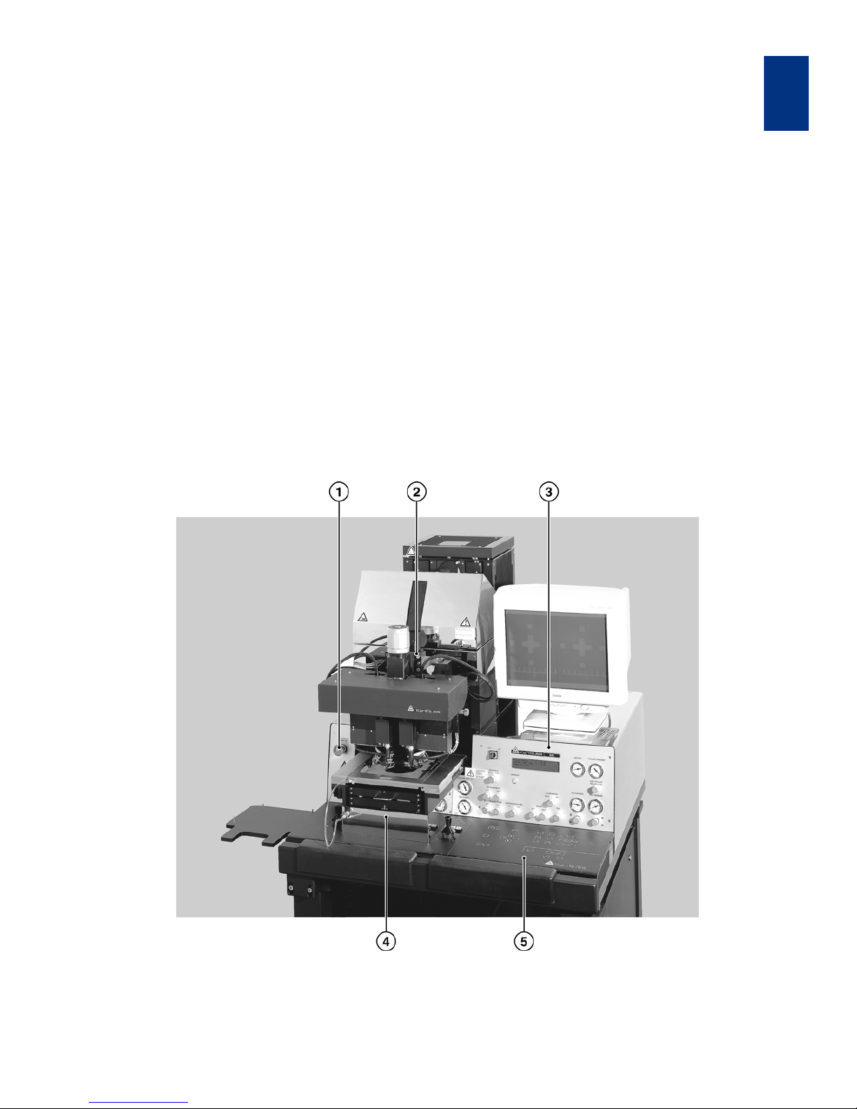
Operation of the Machine
MA6 / MA8 - 1. Operation of the Machine - Rev.05 07-06
1
1
1. OPERATION OF THE MACHINE
The SUSS MA6 Mask Aligner is designed for high
resolution photolithography in a laboratory for devel
opment, small volume production or pilot production
environment.
It offers unsurpassed flexibility in the handling of irregularly shaped substrates of varying thickness, as well
as standard size wafers up to 150 mm in diameter
and substrates up to 6"x 6".
Wafers and substrates up to 6 mm thickness may be
processed.
With the modular concept, the MA6 enable easy service. The functional groups are easily accessible and
the subassemblies can be quickly exchanged.
The SUSS MA6 represents a new generation of state
of the art mask aligners, combining time proven fea
tures with newly developed technology for mask
aligning wafers, substrates and fractions of it. Based
on the proven world wide leader in it's lithography ap
plication for more then three decades the SUSS
MJB3.
With the SUSS MA6, all contact exposure programs
are supplied (vacuum, hard, soft contact and proxim
ity). X- and Y-shift are below 0.1 µm and not detectable by optical means.
The 400 nm exposure wavelength version is capable
of 0.6 µm resolution in vacuum contact. Using 300
nm or 250 nm exposure optics or an excimer laser
improves resolution to 0.2 µm.
Various alignment options are available. Top side
alignment with a splitfield or a video microscope.
Back side alignment with BSA scopes as well as sev
eral infrared alignment solutions.
SUSS Mask Aligner MA6
1 EMERGENCY POWER OFF
2 TSA microscope
3 Upper panel control
4 Alignment stage
5 Keyboard
Page 10
OPERATION OF THE MACHINE
MA6 / MA8 - 1. Operation of the Machine - Rev.05 07-06
1
2
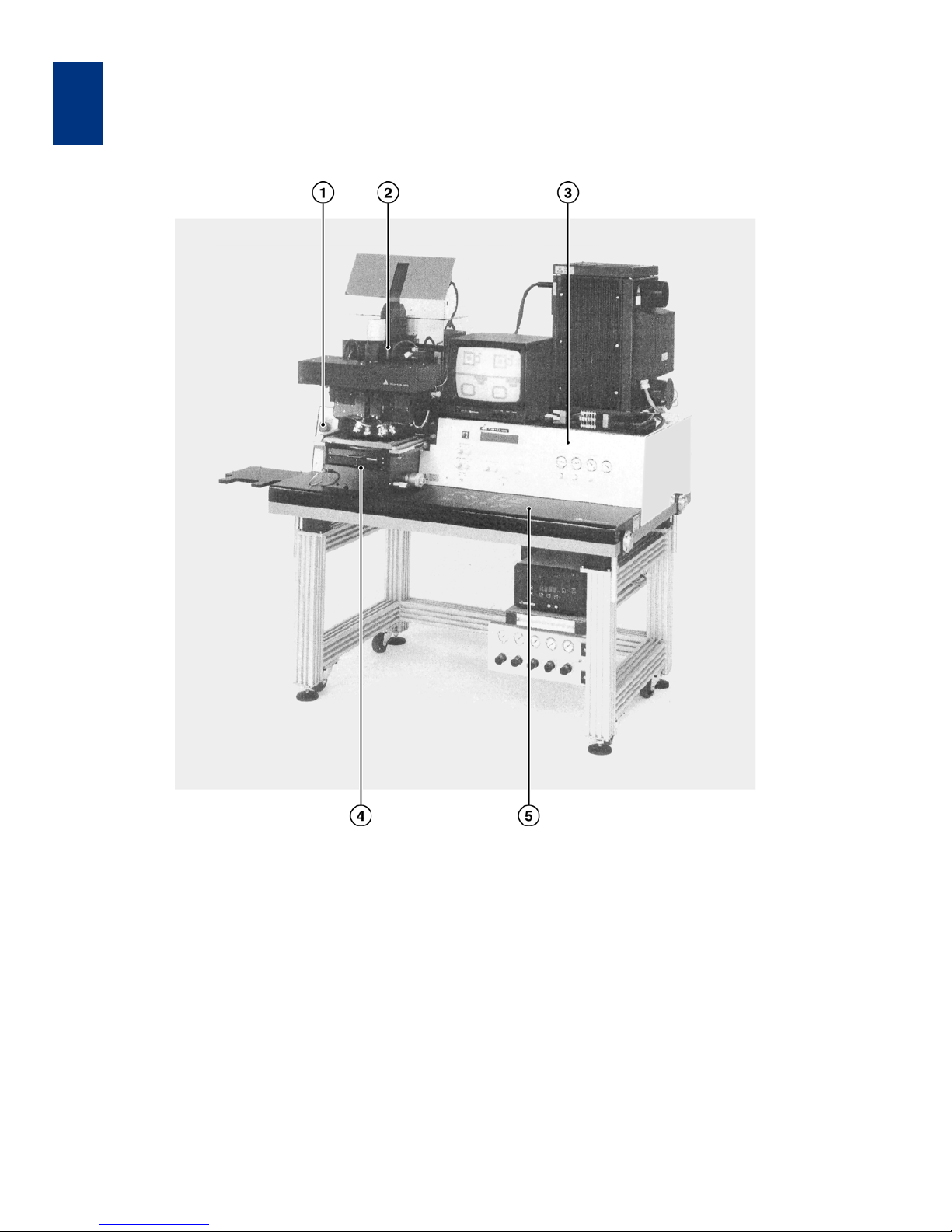
SUSS Mask Aligner MA8
1 EMERGENCY POWER OFF
2 TSA microscope
3 Front panel
4 Alignment stage
5Keyboard
Page 11

Operation of the Machine
MA6 / MA8 - 1. Operation of the Machine - Rev.05 07-06
3
1
1.1 Definitions
1.1.1 How to Use this Manual
Start to reading this manual, some rules are applicable. The name of a control function or control indicator is written in capitals. For example:
EDIT PROGRAM
Refers to the key named edit program. Words shown
in the display are included in quotation marks. For ex
-
ample:
"move slide into machine and confirm
with ENTER"
A warning for the operator of the machine is written
cursive. For example:
Watch out for the microscope movement!
Every operator control function and display is referred
by a number. The first digit of this is equal to the figure
number showing it. For example:
204. VACUUM gauge
This means that the element labeled VACUUM is a
gauge explained as item 4 and is displayed in figure
2. This documentation is for using the machine as a
mask aligner. The term TOP SUBSTRATE (on which
is the upper focus plane) represents the upper sub
strate during bond alignment and a mask during lithography. The term BOTTOM SUBSTRATE (on
which is the lower focus plane) is replaced in the text
by the word wafer for bondalignment and lithogra
-
phy.
1.1.2 Key LED's
Each key of the keyboard except the ARROW keys is
equipped with a light emitting diode, indicating the
following:
–LED on:
key selected or function active
– LED off:
key not selected or function deactivated
– LED flashing:
most applicable key to continue
Page 12
OPERATION OF THE MACHINE
MA6 / MA8 - 1. Operation of the Machine - Rev.05 07-06
1
4
1.1.3 Coordinate Systems
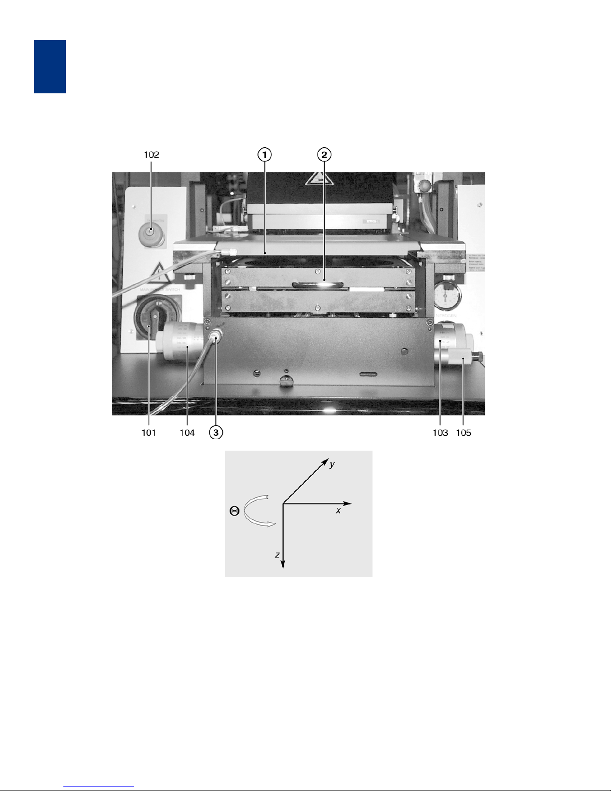
The length units for the x and y-direction are in millimeter. The z-direction length unit is µm. They refer to
a coordinate system whose origin is in the center of
the alignment stage unit. The origin of the z-axis is
equal to the mask plane or upper substrate plane
(see Figure 1).
Alignment Stage with Coordinate System
101 MAIN POWER switch
102 EMERGENCY POWER OFF key
103 Knob STG-X-MOVEMENT
104 Knob STG-Y-MOVEMENT
105 Knob STG-Θ-MOVEMENT
1 Mask holder
2 Transport slide
3 Snap in connector mask vacuum
Page 13
Operation of the Machine
MA6 / MA8 - 1. Operation of the Machine - Rev.05 07-06
5
1
1.1.4 Components of the Exposure
Optics
The components of the optical system are depending on the used lamp house system.
The UV400, UV300, and UV250, exposure optics
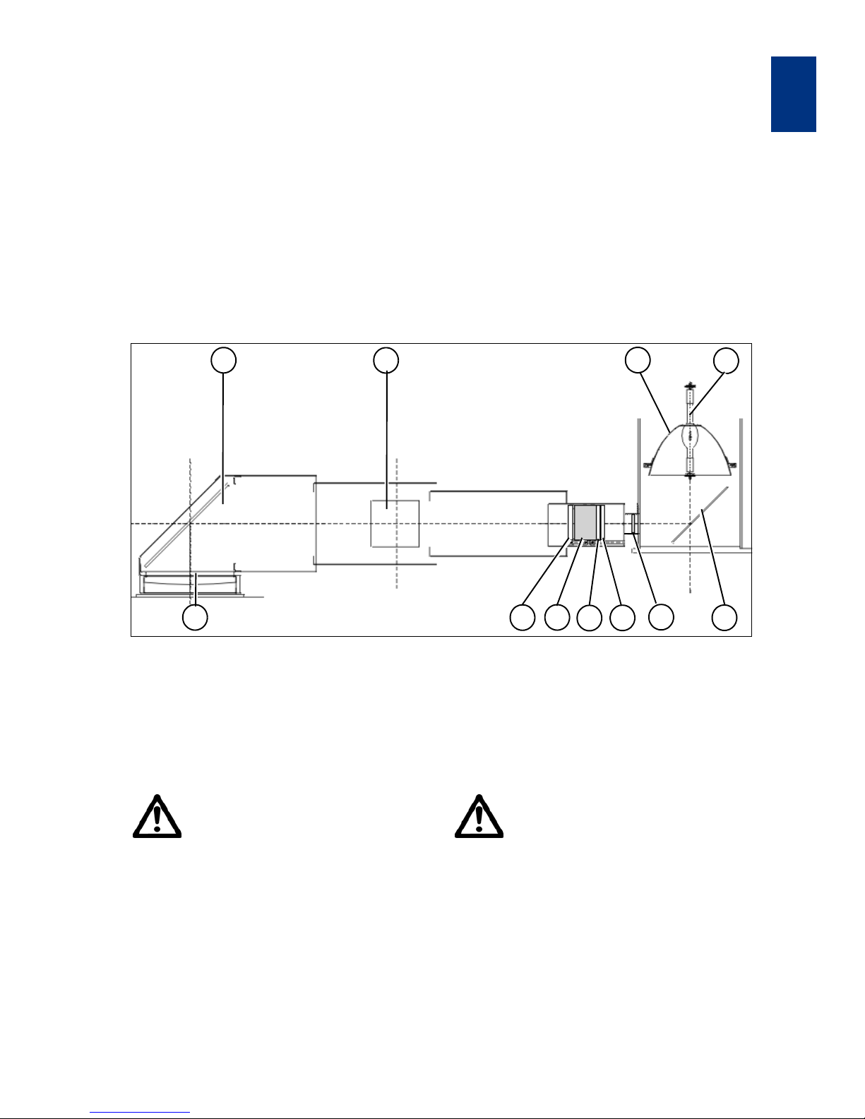
are similar in design. The optical system consists of
an exposure lamp, ellipsoidal mirror, cold light mirror
fly’s eye lens, condenser lenses, lens plates, turning
mirrors and a front lens as shown in the adjacent figure.
The following lamp houses are available:
•LH350
• LH1500/1000
•LH5000
Exposure Optics MA 8 with LH1000
1 Exposure Lamp
2 Ellipsoidal Mirror
3 Cold Light Mirror
4 Fly’s Eye Lens or Glass Window
5 Condenser Lens
Warning!
UV light can harm eyes and skin.
Work on optical components should
be done with the exposure lamp
switched off, or at least with closed
lamp house shutter. If lighting is es
sential for adjustment purposes, wear
UV protecting goggles and skin protection.
6 Filter, optional
7 Integrator Block
8 Field Lens
9 Turning Mirror
10 Front Lens
Essential Note!
Accurate arrangement of optical com-
ponents is essential for the quality of
exposure.
Modify positions or components only if
trained for this job, and when the ap
propriate adjustment procedure is
available.
Also orientation of lenses and the cold
light mirror must not be changed.
1
4
10
8
7
6
5
9
2
3
9
Page 14
OPERATION OF THE MACHINE
MA6 / MA8 - 1. Operation of the Machine - Rev.05 07-06
1
6
1.1.4.1 Exposure Lamp
For the UV400 and UV300 exposure optics, the
standard exposure lamp is a 1000 W high pressure
mercury short-arc lamp in the LH1000.
1.1.4.2 Ellipsoidal Mirror
The exposure lamp is mounted inside an ellipsoidal
mirror in a way that the light source is exactly at its
first focal point. This mirror collects the radiation
emitted by the lamp and focusses it to the second
focal point. The ellipsoidal mirror can be the same
for all exposure optics. But very hight reflection is
available for standard UV400.
1.1.4.3 Cold Light Mirror
The cold light mirror splits the lamp radiation in the
not needed long wavelengths and the exposure
light. The long wavelengths pass through the mirror
and are absorbed by a heat sink. The exposure light
(cold light) is reflected 90° to the integrator optics. A
selective coating determines the reflected wave
lengths. This application range (e.g. UV400) is
marked on the mirror as well as the coated face (by
the tip of an arrow at the edge).
Because of the selective coating at least the cold
light mirror has to be exchanged when ahanging the
light application range.
Warning!
Mirror exchange must be done only by
trained personnel, who understand all
the risks associated with lamp replace
-
ment!
1.1.4.4 Fly’s Eye Lens
This lens disperses the light and directs it to the
condenser lens. The fly’s eye lens is made of optical
grade fused silica for all optical systems.
Alternatively for more intensity but with less unifor-
mity in the exposure area, a glass window (same
material) is available.
1.1.4.5 Condenser Lens
The condenser lens collimates the exposure light.
The position of this lens in the mirror house tube af
fects the intensity and uniformity of the exposure
light. A scale is mounted along the optical bench in
side the house tube. The position of the condenser
lens depends on the type of exposure optics. The
condenser lens is made of optical grade fused sili
-
ca.
1.1.4.6 Filters
The filter is located between the condenser lens
and the integrator block. Filters are used to select
more specific the exposure wavelength then the
cold light mirror can do it or reduce the intensity
(broad band intensity filter). All filters are made of
quartz glass.
1.1.4.7 Integrator Block
The integrator block has two lens plates with an exactly defined distance to each other. For a good u niformity, each single light channel is super
positioned at the exposure plane.The material of
the lenses is optical grade fused silica.
1.1.4.8 Field Lens
For best uniformity and a maximum of intensity of
the exposure light, the field lens overlays each light
channel of the integrator in the exposure plane on
each other. The material of the lens is optical grade
fused silica.
1.1.4.9 Turning Mirror
It deflects the exposure beam to the exposure area.
The coated side of the mirror has to face the beam.
Mirrors with dielectric coating are marked with the
application range and a sign for the coated surface.
Metallized mirrors are broad band mirrors, but not
optimized to spectral areas.
1.1.4.10 Front Lens
This lens provides collimation and uniformity of the
exposure beam. The lens is specific for each wave
length range. For the UV 400 exposure optics the
front lens is fabricated of optical crown glass.
UV300 requires quartz glass.
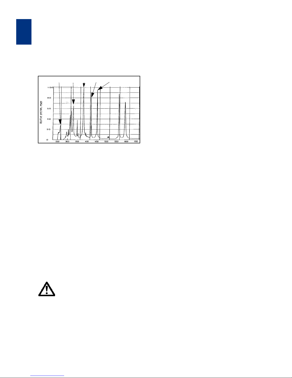
250 nm 313 nm 365 nm 405 nm 436 nm
Page 15
Operation of the Machine
MA6 / MA8 - 1. Operation of the Machine - Rev.05 07-06
7
1
1.1.4.11 Cleaning of Optical Parts
Optical Components can degrade with time by deposition of particles or fumes.
In this case they must be removed from the machine and cleaned very carefully, in order to reconstitute the original quality of the machine.
Optical surfaces are polished and/ or coated. Because of this they are extremely susceptible to mechanical damage. For cleaning they must not be
wiped, but only rinsed with liquid solvent.
No other solvent than DI-water (with or without mild
detergent) or IPA (Isopropyl alcohol) shall be used.
The choice between those depends on the charac
ter of contamination. The final cleaning step should
always use clear DI. If there is any doubt about the
adequate cleaning procedure call SUSS service.
See also instructions in the Maintenance chapter
and in the Preventive Maintenance Manual.
Caution!
To avoid damage on optical compo-
nents, use only recommended solvent
and do not wipe.
Place the part back to the identical position in the exposure optics system as
before
Warning!
When using IPO protect your skin
against contact with the solvent.
IPO is flammable, use it only away from
any ignition source. Do not spill IPO.
Used IPO and tissues soaked with IPO
must be deposited as flammable waste
following local regulations.
For details refer to the host interface documentation
delivered separately. This document describes the
GEM compliant SECS-II interface for the mentioned
equipment. It includes the information required by
the SECS-II and GEM standards including the GEM
State Models, SECS-II Message Documentation,
and other interface details.
1.1.4.12 Deep UV Exposure
Short-wave UV-light (<315nm) has a high biological
radiation effectivness and recommended maximum
dose for skin and eye exposure is very low.
Extended work in front of a laboratory mask aligner at
UV250 or UV300 optics can result in exceeding the
dose limit. Therefore it is recommended not to look to
the stray light, exiting from the mask stage during ex
posure and to keep unprotected hands away from
the stage during exposure.
Warning!
When using UV250 or UV300 then min-
imize eye-and skin- exposure from UV
stray light by increasing your distance
to the stage during exposure times.
SUSS MicroTec could also provide a
special stray light barrier to be placed
on top of the mask holder frame.
Page 16

OPERATION OF THE MACHINE
MA6 / MA8 - 1. Operation of the Machine - Rev.05 07-06
1
8
1.2 Controls and Indicators
101 MAIN POWER switch
This connects the machine to the public power station for electricity.
102 EMERGENCY POWER OFF key
In any case of danger press this button to disconnect
the machine from the public power line.
1.2.1 Alignment Stage Controls
103 Knob STG-X-MOVEMENT
This is located at the right side of the alignment stage
and moves the wafer in x-direction. Maximal travel
±10mm.
104 Knob STG-Y-MOVEMENT
This is located at the left side of the alignment stage
and moves the wafer in y-direction. Maximal travel
±5mm.
105 Knob STG-Θ-MOVEMENT
This is the small knob at the right side of the alignment stage. Maximal travel ±5°.
Page 17
Operation of the Machine
MA6 / MA8 - 1. Operation of the Machine - Rev.05 07-06
9
1
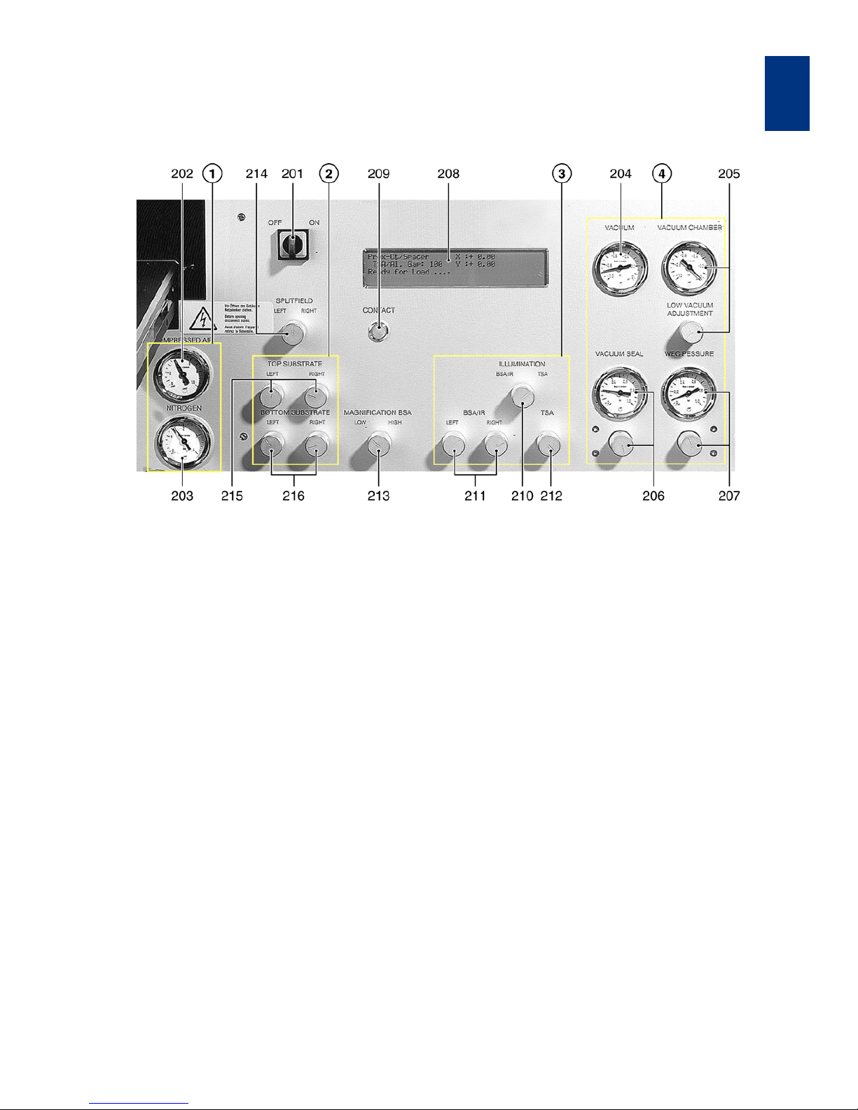
1.2.2 Front Panel Controls
Front panel
Note
Controls of MA8 Front Panel are identical
except their position.
201 POWER SWITCH ELECTRONIC
1 Pressure
202 COMPRESSED AIR gauge
203 NITROGEN gauge
4Vacuum
204 VACUUM gauge
205 VACUUM CHAMBER gauge (with regulator)
206 VACUUM SEAL (with regulator)
207 WEC - PRESSURE gauge (with regulator)
208 LCD-display
209 CONTACT indicator
3 Illumination
210 ILLUMINATION switch
211 BSA/IR microscope illumination
212 TSA microscope illumination
213 MAGNIFICATION BSA switch
214 SPLITFIELD switch
2Substrate
215 TOP SUBSTRATE LEFT/RIGHT
216 BOTTOM SUBSTRATE LEFT/RIGHT
322 BSA MICROSCOPE key
323 LEFT key
324 BOTH key
325 RIGHT key
326 TOP/BOTTOM key
Page 18

OPERATION OF THE MACHINE
MA6 / MA8 - 1. Operation of the Machine - Rev.05 07-06
1
10
201 POWER SWITCH ELECTRONIC
Start the MA6 by turning the switch shortly clockwise
to ON and release. Stop the MA6 also by turning the
switch shortly clockwise to OFF and release.
202 COMPRESSED AIR gauge
The machine operates properly when the pressure is
set to 5 bar. The air pressure is controlled by a regu
-
lator adjusted by a service engineer.
203 NITROGEN gauge
N2 gas is used to cool the exposure lamp, establish
a nitrogen "pillow" under the wafer (hard contact ex
posure), purge the wafer exposure area, and to break
residual vacuum after vacuum contact and other sec
ondary functions. At 1 bar N2 (adjusted by a service
engineer) the machine operates properly.
204 VACUUM gauge
The vacuum supplied to the machine should be
-0.8 bar related to normal air pressure what means
0.2 bar absolute pressure.
205 VACUUM CHAMBER gauge
(with regulator)
The gauge indicates the vacuum level in the vacuum
chamber during exposure. The vacuum level is ad
justed opening a N2 leak valve. Open the vacuum restrictor LOW VACUUM ADJUSTMENT below the
gauge counter clockwise. Close it by turning the
knob clockwise.
206 VACUUM SEAL (with regulator)
The required pressure to inflate the rubber lip (necessary to create the vacuum chamber) should be set to
a value p = 0.1 to 0.2 bar for standard thickness wa
fer according SEMI specification. Thicker wafer might
need a slightly higher pressure. A improper high pres
sure could create an overcurrent error.
207 WEC - PRESSURE gauge (with regulator)
To perform the wedge error compensation the wafer
must be pressed with a defined force against the
mask. The WEC-pressure is used to compensate the
higher gravitation force of a bigger chuck. The WECpressure also must be changed proportional to a
change of the wafer area. The air pressure for the
WEC-head can be set in accordance with your pro
cess requirements (range 0.2 and 1.0 bar). This is
done with the corresponding regulator below the
gauge.
208 LCD-display
This user interface displays instructions, confirmations and other messages.
209 CONTACT indicator
That lamp lights whenever mask and wafer or two
wafers for bond alignment are in contact. If you move
the wafer manually further up, this indicator starts
flashing.
210 ILLUMINATION switch
The illumination is supplied either to the TSA or BSA
microscope by way of fiber optic light cables from a
light source. BSA illumination is selected in the BSA/
IR position.
211 BSA/IR microscope illumination
The potentiometers labeled LEFT and RIGHT realize
the fine illumination adjustment for the two objectives
of the BSA microscope (BSA/IR is selected).
212 TSA microscope illumination
The fine illumination adjustment is performed with the
TSA adjustment knob. For the coarse adjustment use
control 501 (see chapter 3.2.5 Lamp house controls).
213 MAGNIFICATION BSA switch
Select between low and high magnification.
214 SPLITFIELD switch
With the rotary switch in middle position, the left/right
objective image is shown on the left/right half side of
the video monitor simultaneously. With the switch in
right or left position, the right/left objective image is
displayed on the whole video monitor. Only for the
microscope type M3xx this switch must be in left po
sition and the splitfield must be selected at the microscope itself.
215 TOP SUBSTRATE LEFT/RIGHT
In order to improve the image of the mask structures
displayed on the video monitor only minor focus ad
justments are necessary. The two potentiometers individually control the fine focus of the BSA and TSA
microscope objectives at the upper focus plane.
216 BOTTOM SUBSTRATE LEFT/RIGHT
In order to improve the image of the wafer structures
displayed on the video monitor only minor focus ad
justments are necessary. The two potentiometers individually control the fine focus of the BSA and TSA
microscope objectives at the lower focus plane.
Page 19
Operation of the Machine
MA6 / MA8 - 1. Operation of the Machine - Rev.05 07-06
11
1
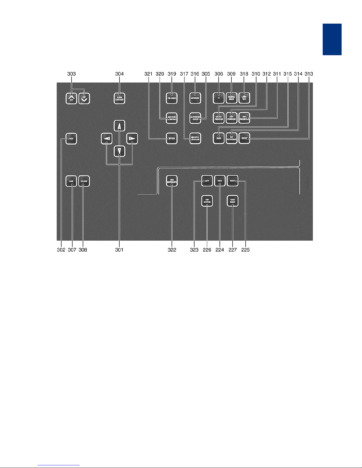
1.2.3 Keyboard Controls
Keyboard
301 X, Y-ARROW keys
302 FAST key
303 SEP keys
304 ALIGN CONT/EXP key
305 ALIGNMENT CHECK key
306 F1 key
307 LOAD key
308 UNLOAD key
309 CHANGE MASK key
310 SELECT PROGRAM key
311 EDIT PARAMETER key
312 EDIT PROGRAM key
313 ENTER key
314 SET REFERENCE key
315 SCAN key
316 EXPOSURE key
317 Multiple Exposure key
318 LAMP TEST key
319 PRE-BOND key
320 PERFORM CLAMPING key
321 OPTION key
322 BSA MICROSCOPE key
323 LEFT key
324 BOTH key
325 RIGHT key
326 TOP/BOTTOM key
327 GRAB IMAGE key
Page 20
OPERATION OF THE MACHINE
MA6 / MA8 - 1. Operation of the Machine - Rev.05 07-06
1
12
301 X, Y-ARROW keys
The function of these keys depends on the task performed:
– movement of the upper microscope (TSA)
– movement of the lower microscope(BSA)
– movement of the wafer (only motorized stage)
(STG)
– selection of next/last parameter in the control soft-
ware (X-arrows)
– change of parameter values (Y-arrows)
Arrow keys marked with X are labeled with an triangle
pointing to the right/left. To move the manipulators
along the X-axis press one of this keys. Arrow keys
marked with Y are labeled with an triangle pointing
upward/downward. To move the manipulators along
the Y-axis press one of this keys. In case the manip
ulator reaches one/both limit positions along the Xand/or Y-axis, the message on the monitor indicates:
"HW or SW limits active - use ARROW
keys"
to move back into regular range use the key for the
opposite direction.
302 FAST key
Activating this key (LED is ON) enables the movement
of the microscope manipulator and motorized stage
if existing into the desired direction with the fast
speed (otherwise the movement is performed with
the slow speed). The speed level can be adjusted
with function F1 - change align speed (see explana
-
tions to key F1).
303 SEP keys
The keys are labeled with an arrow pointing upward
and downward and marked with SEP (separation).
With these keys the alignment position of the wafer
can be changed in steps of 1 µm along the z-axis.
The keys are active after WEC. Moving to mask con
tact the CONTACT indicator lights on. Further moving
the wafer up this indicator flashes.
If mask and wafer are in contact
(CONTACT INDICATOR on),
don't align the wafer!
304 ALIGN CONT/EXP key
Acts as a toggle switch. The operator can quickly
change the position of the wafer between alignment
gap and exposure position relative to the mask.
If mask and wafer are in contact
(CONTACT INDICATOR on),
don't align the wafer!
305 ALIGNMENT CHECK key
With this key one can check the alignment prior exposure. Particles between mask and wafer or the
edge bead can affect the alignment of the wafer to
the mask. To test that the alignment remains stable
while moving to exposure position, all parameters of
the exposure program are triggered except the expo
sure itself. This key is active for the exposure programs: Vacuum Contact, Low Vacuum Contact, and
Hard Contact. For example: starting the exposure
program "Vacuum Contact" triggers the pneumatic
procedures:
Pre Vac and Full Vac:
To check the possible influence of these unexpected
factors before exposure, press the ALIGNMENT
CHECK key. Press this key again to release the wafer
back into alignment gap.
If mask and wafer are in contact
(CONTACT INDICATOR on),
don't align the wafer!
306 F1 key
If one wishes to leave the variable unchanged, simply
press the flashing F1 key.
The different functions of F1 key are:
– Microscope up/down
During loading, aligning and exposure the microscope does all necessary up and down movements automatically. For a better view to mask
and wafer this is manually possible by using the
F1 key.
– Change alignment speed
The user can select between slow and fast alignment speed by the FAST key. The speed selected
by the FAST key (fast or slow) will be displayed
here. Select the desired alignment speed for the
microscopes and motorized stage (if existing).
The Y-ARROW keys change the parameter value,
the X-ARROW keys toggle between the TSA, BSA
and STG parameter. Pressing the FAST key en
ables the adjustment of the other speed parameter (see also 3.5.4 Changing the TSA, BSA and
stage alignment speed).
– Single step config
Define the step width for the alignment stage
movement per each depression of a arrow key.
– Centering stage
For every WEC procedure the alignment stage
move to the center position for x, y and Θ. Center
ing stage on (default) means, the wafer goes to
alignment gap keeping this center position. Cen
-
tering stage off means, the alignment stage move
Page 21

Operation of the Machine
MA6 / MA8 - 1. Operation of the Machine - Rev.05 07-06
13
1
to the X-, Y- and Θ-position used during the previous alignment at time of EXPOSURE key activation. In case a prior saved program contains this
position values, it will be activated.
– Select maskloading
The two options for the loading process are:
• load manually (default)
• load by slide
For Load by slide it's possible to select between:
• without alignment of the mask (no align)
• with BSA alignment of the mask (BSA align)
Both loading procedures are described separately
(see chapters 3.3.2 First mask print mode and 3.5.8
Load mask by slide).
– Scope synchron.
Infrared light is used to look through Wafer which
are opaque for visible light. The light is locally sup
plied using the BSA microscope arms. The TSA
microscope is used as a transmitted light micro
scope. Synchronous movement of TSA and BSA
microscope is necessary. To enable this, deacti
vate the BSA MICROSCOPE key. Switch the ILLUMINATION switch (210) to BSR/IR and (if
existing) the IR switch on. Adjust the TSA-objec
tives by the OBJECTIVE X-SEPARATION knobs
(405) to the location of the IR-light supply. The
synchronous scope movement is only possible by
the arrow keys.
– Single BSA al.
Use this special function to align substrates which
alignment mark distance is smaller then the mini
mum distance of the BSA objectives. For this case
use only one objective in connection with the SET
REFERENCE key and SCAN key. For detailed in
structions read chapter 3.3.5.
– WEC-delay
A large wafer needs longer time to set itself exactly parallel to the mask. This is necessary to get
high quality mask prints of small structures over
the whole wafer. The necessary time must be
tested and set by the operator.
307 LOAD key
After the machine has been powered on, the LED of
the LOAD key is flashing. Hit the LOAD key to finalize
the boot procedure.
Press the LOAD key to start the wafer loading procedure.
308 UNLOAD key
If one wishes to unload the wafer, press this key. This
key also terminates some working sequences. Press
ing UNLOAD after starting the exposure cycle the exposure sequence will be completed without exposure
itself.
309 CHANGE MASK key
Starting from the initial screen the operator initiates
the procedure for changing (loading/unloading) of the
mask.
Unload the mask before powering off
the machine!
310 SELECT PROGRAM key
Select one of the six exposure programs of the machine (see also chapter 3.5.2).
311 EDIT PARAMETER key
After the desired exposure program has been selected, press the EDIT PARAMETER key. Edit the parameter of the exposure program. The parameter is
changed with the corresponding Y-directional arrow
key. The next parameter is selected by the X-direc
tional arrow key. The number of parameters depends
on the selected exposure program (see also chapter
3.5.3).
312 EDIT PROGRAM key
This key enables the operator to assign all parameter
settings and the microscope position to a program
number ranging from [0] to [99]. This number helps to
keep all settings in the nonvolatile memory (see also
chapter 3.5.5):
–save
after exposure program selection and the parameter adjustment, press the EDIT PROGRAM key
and toggle to "save" using the x-ARROW keys.
Assign a program number using the y-ARROWkeys. Press ENTER key to save it. A former saved
program to this number will be overwritten.
–load
press the EDIT PROGRAM key and toggle to
"load". Select a program number to load a former
saved program. Press ENTER key to load it.
–delete
press the EDIT PROGRAM key and toggle to "delete". Select a program number to delete. Delete
the displayed program.
Page 22

OPERATION OF THE MACHINE
MA6 / MA8 - 1. Operation of the Machine - Rev.05 07-06
1
14
313 ENTER key
Press the ENTER key to confirm an action whenever
the program prompts you to do so.
314 SET REFERENCE key
The SET REFERENCE key enables the operator to
store the actual microscope position of the TSA or
BSA microscope as reference position. This is neces
sary for the SCAN key function. This can be used also
for the alignment stage.
315 SCAN key
This key can be used only after a reference position
for the selected microscope with the SET REFER
ENCE key is stored (i.e. the position for the first alignment mark). Then the microscope can be moved to a
new position (i.e. the position for the second align
ment mark). Activating the SCAN key toggle the position of the microscope between the current position
and the reference position. This can be used also for
the alignment stage.
316 EXPOSURE key
This key starts the active exposure program after an
alignment or in first mask print mode.
317 Multiple Exposure key
It is possible to split the exposure in several intervals.
The key must be activated for this (LED on). See also
chapter 3.4.2.
318 LAMP TEST key
Pressing this key moves the mirror house forward
and open the light shutter. Exposure intensity and
uniformity adjustment is possible. Deactivating this
key finish this task.
319 PRE-BOND key
Enabled only in the bond-aligner-mode: this moves
the wafers together and the vacuum sequence starts.
320 PERFORM CLAMPING key
Enabled only in the bond-aligner-mode: this clamps
the wafers together with or without spacers.
321 OPTION key
The X-ARROW keys controls the Θ-movement for the
motorized alignment stage when OPTION key is acti
-
vated.
322 BSA MICROSCOPE key
Toggles the motor control and image processing between TSA (LED off) and BSA (LED on) microscopes.
323 LEFT key
For BSA alignment only the movement of the left objective is possible.
324 BOTH key
The simultaneous movement of both BSA-objectives
is possible.
325 RIGHT key
For BSA alignment only the movement of the right
objective is possible.
326 TOP/BOTTOM key
Toggle the focus plane between mask plane (LED on)
and wafer plane.
327 GRAB IMAGE key
By activating this key the current monitor image is
stored as background image to be superimposed
with the wafer image later on.
Page 23
Operation of the Machine
MA6 / MA8 - 1. Operation of the Machine - Rev.05 07-06
15
1
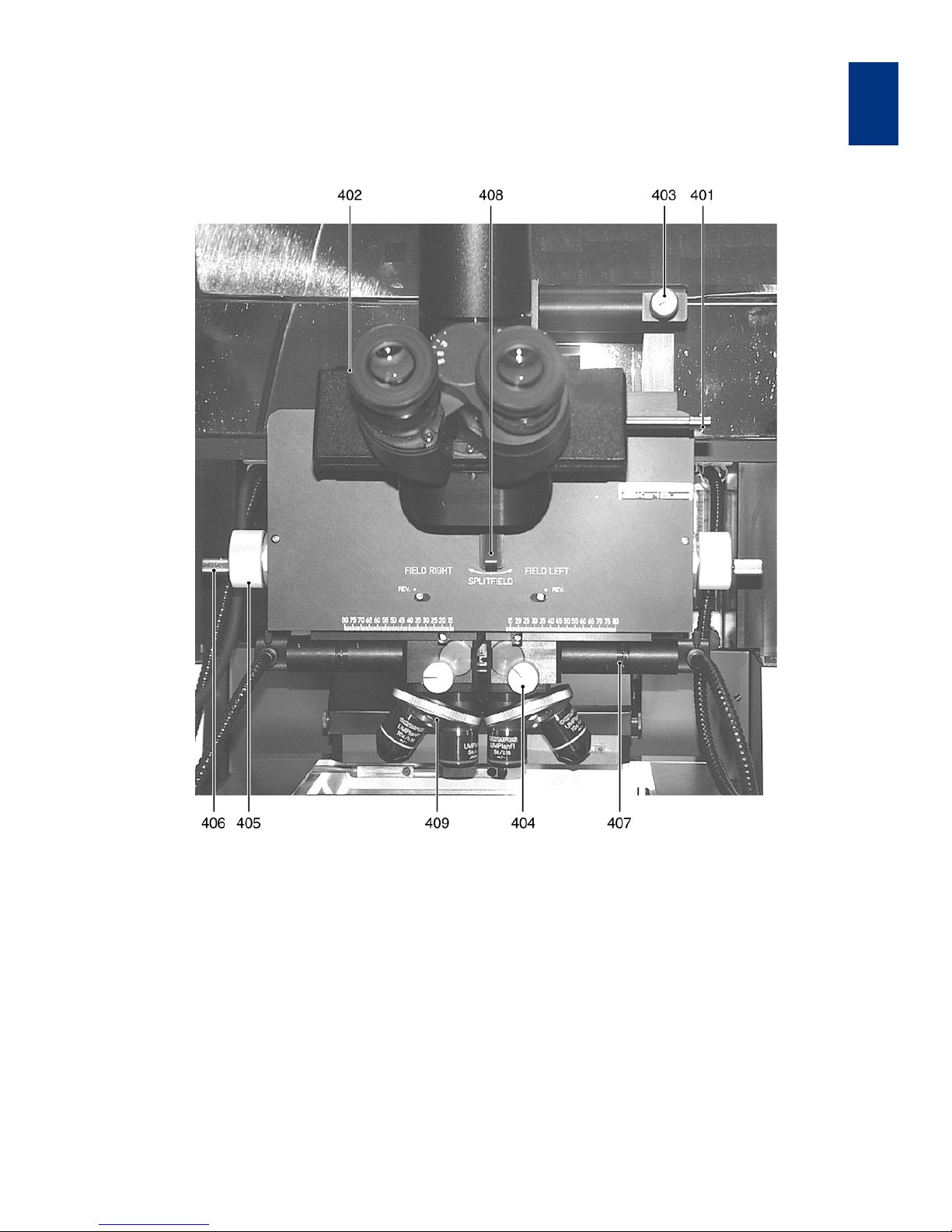
1.2.4 TSA-Microscope Controls
TSA-Microscope M 336
401 BEAM SPLITTER TSA
402 TSA Z-MOVEMENT knob
403 TSA Θ-MOVEMENT knob
404 OBJECTIVE FOCUS FINE MANUAL knob
405 OBJECTIVE X-SEPARATION knobs
406 CLAMPING SCREW
407 APERTURE TSA-Illumination
408 TSA SPLITFIELD switch
409 Turret
Page 24

OPERATION OF THE MACHINE
MA6 / MA8 - 1. Operation of the Machine - Rev.05 07-06
1
16
1.2.4.1 M 3xx Microscope
Before using the microscope make secure the TSA illumination (control 210) is on and the BSA MICROSCOPE key is off. Turn the SPLITFIELD switch
(control 214) on the front panel to left to get the TSA
image on the monitor.
401 BEAM SPLITTER TSA
This slide on right side of the microscope tube guide
the beam to the eyepieces, the monitor or both.
402 TSA Z-MOVEMENT knob
The fine movement works at any position in a range
less than on turn and with a low torque. Continuing
rotation increases the torque and enables the coarse
adjustment.
403 TSA Θ-MOVEMENT knob
Rotates the microscopes around the z-axis by turning the knob located in the upper right TSA microscope front.
404 OBJECTIVE FOCUS FINE MANUAL knob
For the M 3xx without motorized focus, fine focus of
the left/right objective is possible by the left/right
knobs only.
405 OBJECTIVE X-SEPARATION knobs
The right/left objective can move independently in xdirection by the big knobs located in the right/left side
of the TSA microscope body. Never turn this screw
when the CLAMPING SCREW is fixed.
406 CLAMPING SCREW
This has two functions. First it acts as a crank. Second it is used to clamp a certain objective position.
Press that knob gentle toward the microscope body
and turn clockwise. To release turn in the opposite di
-
rection until it snaps out.
407 APERTURE TSA-Illumination
This right/left aperture at TSA-microscope front adjusts the illumination for the right/left TSA-objective
separately.
408 TSA SPLITFIELD switch
Located on the microscope front this switch selects
the left, right or both TSA-objective as source for the
eyepieces and monitor image.
409 Turret
Turn the knurled ring to move another objective in the
beam.
Page 25
Operation of the Machine
MA6 / MA8 - 1. Operation of the Machine - Rev.05 07-06
17
1
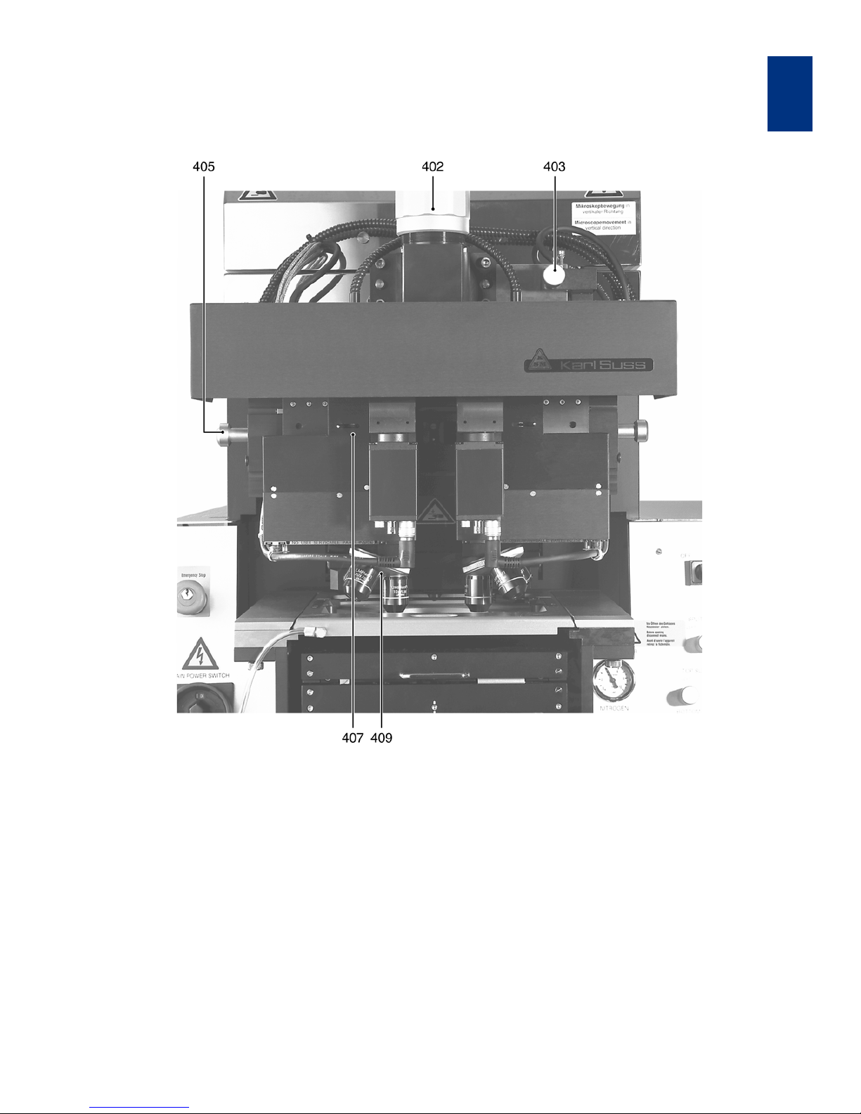
Dual Video Microscope DVM 6
402 TSA Z-MOVEMENT Knob
403 TSA Θ-MOVEMENT knob
405 OBJECTIVE X-SEPARATION knobs
407 APERTURE TSA-Illumination
409 Turret
Page 26
OPERATION OF THE MACHINE
MA6 / MA8 - 1. Operation of the Machine - Rev.05 07-06
1
18
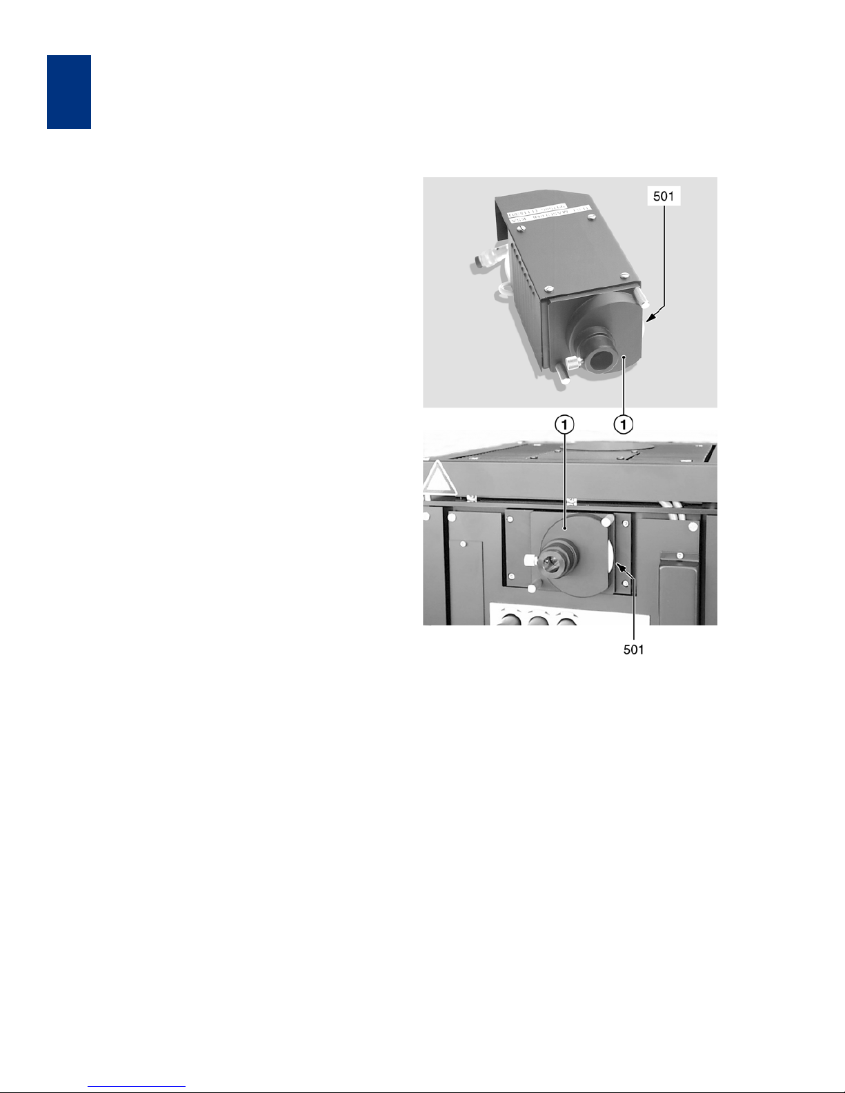
1.2.4.2 Dual Video Microscope DVM 6/8
Before using the microscope make secure the ILLUMINATION TSA (210) is on and the BSA MICROSCOPE key is off.
401 BEAM SPLITTER TSA
On this microscope not necessary.
402 TSA Z-MOVEMENT Knob
Turn this big knob to focus the microscope coarse.
403 TSA Θ-MOVEMENT knob
Rotates the microscopes around the z-axis by turning the knob located in the upper right TSA microscope front.
404 OBJECTIVE FOCUS FINE MANUAL knob
This is a motorized focus here.
405 OBJECTIVE X-SEPARATION knobs
The right/left objective can move independently in xdirection by the big knobs located in the right/left side
of the TSA microscope body.
406 CLAMPING SCREW
Does not exist at this microscope.
407 APERTURE TSA-Illumination
This right/left aperture at TSA-microscope front adjusts the illumination for the right/left TSA-objective
separately.
408 TSA SPLITFIELD switch
This function is electronically realized. See the manual
for the corresponding image processing system.
409 Turret
Turn the knurled ring to move another objective into
the beam.
1.2.5 Lamp House Controls
Lamp house LH 350 and LH 1000
501 Illumination adjustment coarse
1 Thumb wheel housing
501 ILLUMINATION ADJUSTMENT COARSE
For a coarse adjustment of the light intensity turn the
thumb wheel at the microscope light source. Turn
clockwise / counterclockwise to open/close the ap
erture. The big thumb wheel ILLUMINATION ADJUSTMENT COARSE (501) has a diameter of nearly
5 cm, 0.5 cm thick.
For the lamphouse LH 350 find the adjustment wheel
behind the lamp house. It might be necessary to re
move the left stainless steel cover of the lamphouse
to have access to the microscope illumination.
For the lamphouse LH 1000 find the adjustment
wheel on the upper front side of the lamphouse.
Lamp exchanging is possible opening the two
knurled screws.
Page 27
Operation of the Machine
MA6 / MA8 - 1. Operation of the Machine - Rev.05 07-06
19
1
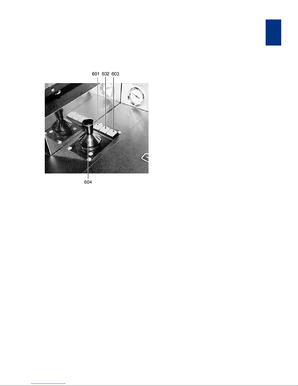
1.2.6 Joystick and Buttons
(motorized stage only)
Joystick keys
601 STG/TSA/BSA button
602 CONT/ALIGN/EXP button
603 SINGLE STEP button
604 X-Y-JOYSTICK
601 STG/TSA/BSA button
• Illuminated:
Joystick and arrow keys controls the alignment
stage motors.
• Dark:
Joystick and arrow keys control the TSA or BSA
motors depending on the status of the BSA MI
-
CROSCOPE key (see 322).
602 CONT/ALIGN/EXP button
The wafer is in alignment position if this button is activated, otherwise the wafer is in exposure position.
603 SINGLE STEP button
Every joystick flexure or arrow key depression will
only result in a single step movement in accordance
with the value programmed via the F1 key.
604 X-Y-JOYSTICK
Flexure the joystick located on the right side of the
alignment stage in this direction in which the micro
scope/alignment stage should move. Release if final
position is reached. The movement speed increase
by a stronger joystick flexure. Activating FAST key al
-
lows fast movement.
605 Θ-JOYSTICK (alignment stage only)
This joystick is located at the left side of the alignment
stage. Flexure in x-direction rotates the wafer in fast
speed clockwise or back. Flexure in y-direction ro
-
tates the wafer in slow speed clockwise or back.
Page 28

OPERATION OF THE MACHINE
MA6 / MA8 - 1. Operation of the Machine - Rev.05 07-06
1
20
1.3 Operating Procedures
A condensed step by step operation instruction is described in chapter 3.5 Step by step machine interactions.
1.3.1 Power on Procedure
A. Before powering on the machine check or ad-
just
– Compressed Air: 5 bar
– Nitrogen: 1 bar
– Vacuum. The gauge should read -0.8 bar
Turn the MAIN POWER switch (on left side of alignment stage) to the ON position.
B. Ignition of the exposure lamp (CIC 1200)
POWER SWITCH ELECTRONIC of the machine
should be OFF. Switch on power of the Constant In
tensity Controller (CIC). The software version is
shown in the display. The CIC performs a self calibra
tion test and displays "ready". Press CP (constant
power) key. Display shows "wait", followed by "Start".
Press START key. This will ignite the exposure lamp.
LED LAMP LIFE/POWER is flashing until lamp warm
ing up is finished. For more detailed information use
the CIC-manual.
Attention! Nitrogen failure for longer
then 5 minutes will turn off the
exposure lamp!
C. Starting the machine
Shortly turn the POWER SWITCH ELECTRONIC
(201) on the frontpanel clockwise into ON position
and release. Machine initialize. An example for the
display message is:
"Ready for Start - press LOAD Button
MA6-BA6-[M] V 4.000 04.05.01 SW:P"
The meaning of the second displayed line is:
configuration software version date includ-
ed options (here: purge)
Press the flashing LOAD key on the keyboard.
"Watch out machine is starting!"
Now you are asked for:
"Select machine configuration: MA6"
Select between mask align- (MA6) and bond align(BA6) operation mode (with the Y-ARROW keys). Af
ter this selection the software is loaded and the machine is in a initial state, ready for operate and
displays:
"Ready for load"
All motorized manipulators (TSA, BSA and alignment
stage) are set to the position used before the ma
chine was powered off. For your information: if you
need a software reset, press the key combination
FAST - UNLOAD (nearly 200ms time distance). Keep
the EDIT PARAMETER key (311) pressed down while
power on the POWER SWITCH ELECTRONIC (201)
overwrites all parameter settings with the default val
ues from the EPROM. Power off the machine by turning the POWER SWITCH ELECTRONIC (201) on the
front panel counterclockwise into OFF position and
release.
1.3.2 First Mask Print Mode
The first mask print of a wafer is done without alignment. This software sequence is started by the EXPOSURE key. Starting from the initial state of the
machine this steps has to be performed:
1. Adjust Parameters
– select mask loading type: F1 key
Ma k e secur e that no m ask is lo aded bef ore sele ct
mask loading type.
– select exposure mode: SELECT PROGRAM key
Press SELECT PROGRAM key (310). Toggle
through the menu and confirm your exposure pro
-
gram by pressing SELECT PROGRAM key again.
– edit parameters: EDIT PARAMETER key
Press EDIT PARAMETER key (311) to edit the parameter. Change all necessary value and confirm
by pressing EDIT PARAMETER key again.
– save all settings: EDIT PROGRAM key
This function is an optional possibility to save this
parameter set for the future. Toggle with the XARROW keys to "SAVE Pgm.". Select with the YARROW keys a program number. Prior saved
programs to the same number will be overwritten
without warning. Save the settings by the EDIT
PROGRAM key (312). Existing programs can be
loaded from here.
Page 29
Operation of the Machine
MA6 / MA8 - 1. Operation of the Machine - Rev.05 07-06
21
1
2. Load Mask
Watch out for the microscope
movement!
– start mask loading sequence: CHANGE MASK
key
You have to take out the mask holder, flip it 180°
and put it on the tray left. If a mask is loaded,
press ENTER to toggle the mask vacuum off, re
tract the mechanical mask clamp and remove the
mask.
– load mask and fix it: ENTER key
Place the mask onto the mask holder against the
stop pins. Toggle the mask vacuum on by press
ing the ENTER key. Activate the mechanical mask
clamp by pressing on the leaf spring.
– slide the mask holder back into the machine and
clamp it: CHANGE MASK key
Flip the mask holder 180° back and move it into
the machine. Lock the mask holder slide by
pressing CHANGE MASK key again.
3. Load Wafer
– first pull out transport slide and load wafer: EXPO-
SURE key
The machine instructs: "pull slide and load substrate onto chuck". Pull out the transport slide
completely. Insert the proper chuck and place the
wafer against the prealignment pins. Confirm with
ENTER key. Now the wafer is hold by vacuum.
– move slide in: ENTER key
The machine instructs: "move slide into machine
and confirm with ENTER"
– wedge error compensation
WEC starts automatically after the last action is
completed. The wafer is adjusted parallel to the
mask.
4. Exposure
After WEC the wafer moves automatically in exposure position. Depending on the exposure program
selected all program steps will be performed auto
matically. Exposure takes place. After finishing the
wafer chuck moves down to unload the exposed wa
-
fer.
5. Unload Mask: CHANGE MASK key
Hit the CHANGE MASK key and the mask holder will
be released. Pull the mask holder out, flip it by 180°
and store it on the tray to your left. Hit ENTER to
switch the mask vacuum off. Retract the mechanical
clamping and remove the mask.
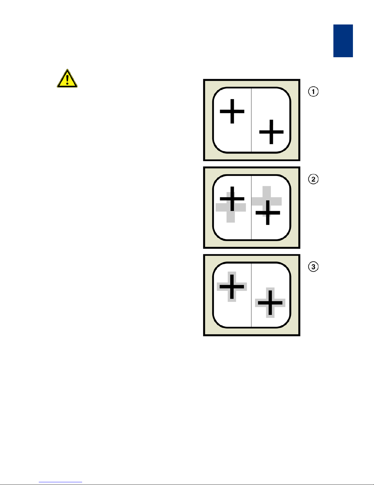
1.3.3 Top Side Alignment
Alignment Procedure
1 Grabbed mask alignment marks
2 Superimposed wafer alignment marks
3 Alignment marks central symmetrical aligned
In this mode the wafer is aligned to the mask using
the topside alignment microscope (TSA). The follow
ing example explains the steps to align and expose
with manual mask loading, soft contact print and
WEC-type contact. Starting from the initial state of
the machine these tasks must be performed:
Page 30

OPERATION OF THE MACHINE
MA6 / MA8 - 1. Operation of the Machine - Rev.05 07-06
1
22
1. Adjust Parameters
– select mask loading type: F1 key
Make secure that no mask is loaded before select
mask loading manual (default).
– select alignment microscope
Deactivate BSA MICROSCOPE key (LED off).
– select exposure mode: SELECT PROGRAM key
Press SELECT PROGRAM key (310). Toggle
through the menu and confirm the selection soft
contact by pressing SELECT PROGRAM key
again.
– edit parameter: EDIT PARAMETER key
Press EDIT PARAMETER key (311) to edit the parameter exposure time, alignment gap and WECtype. Change all necessary value and confirm by
pressing EDIT PARAMETER key again.
– save all settings: EDIT PROGRAM key
This function is an optional possibility to save this
parameter set for the future. Toggle with the XARROW keys to "SAVE Pgm.". Select with the YARROW keys a program number. Prior saved
programs to the same number will be overwritten
without warning. Save the settings by the EDIT
PROGRAM key (312). Existing programs can be
loaded from here.
2. Load Mask
Watch out for the microscope
movement!
– start mask loading sequence: CHANGE MASK
key
You have to take out the mask holder, flip it 180°
and put it on the tray left. If a mask is loaded,
press ENTER to toggle the mask vacuum off, re
tract the mechanical mask clamp and remove the
mask.
– load mask and fix it: ENTER key
Place the mask onto the mask holder against the
stop pins. Toggle the mask vacuum on by press
ing the ENTER key. Activate the mechanical mask
clamp by pressing on the leaf spring.
– Slide the mask holder back into the machine and
clamp it: CHANGE MASK key
Flip the mask holder 180° back and move it into
the machine. Lock the mask holder by pressing
CHANGE MASK key again.
3. Load Wafer
– pull out transport slide and load wafer: LOAD key
The machine instructs: "pull slide and load substrate onto chuck". Pull out the transport slide
completely. Insert the proper chuck and place the
wafer against the prealignment pins. Confirm with
ENTER key. Now the wafer is hold by vacuum.
– move slide in: ENTER key
The machine instructs: "move slide into machine
and confirm with ENTER"
Watch out for the microscope
movement!
– wedge error compensation
WEC starts automatically after the last action is
completed. The wafer is adjusted parallel to the
mask and moves to the alignment gap. The mi
-
croscope moves down to start the alignment.
4. Microscope Alignment
– set the TSA to meet your requirements (see
3.2.4): SPLITFIELD switch
For the M3xx microscope only, an actual TSA-microscope image on the monitor is enabled by
turning the SPLITFIELD switch (214) to LEFT.
Toggle BSA MICROSCOPE key (322) off. This key
switch also the controlled manipulator motors
from BSA to TSA. If no camera and monitor ex
-
ists, use the microscope eyepieces.
– microscope illumination: ILLUMINATION to TSA
Turn ILLUMINATION switch (210) to TSA and select the light intensity by the potentiometer under
this switch. Separate intensity selection for the
left/right objective is possible with the aperture lo
-
cated at the left/right microscope front.
– focus on the mask plane: TOP/BOTTOM key
Coarse focus is possible by using the TSA ZMOVEMENT knob (402) placed behind the TSAmicroscope. Make secure the TOP/BOTTOM key
LED (326) is on and adjust the fine focus sepa
rately using the TOP SUBSTRATE LEFT/RIGHT
(215) regulators. If no motorized focus exist, use
the OBJECTIVE FOCUS FINE MANUAL (404 ) on
the microscope.
– adjust microscope to the mask alignment marks
Move the left/right objective to the left/right mask
alignment mark by the OBJECTIVE X-SEPARA
-
TION knobs (405).
– grab image: GRAB IMAGE key (option)
First keystroke grabs the image. The objectives
move the focal plane to the wafer and theTOP/
BOTTOM key LED (326) goes off. The motor con
trol of the microscope manipulator is disabled at
this time. Second keystroke delete the stored im
age and enables the manipulator again.
Page 31
Operation of the Machine
MA6 / MA8 - 1. Operation of the Machine - Rev.05 07-06
23
1
5. Wafer Alignment
– focus on the wafer plane
Adjust the left/right microscope image with the
BOTTOM SUBSTRATE LEFT/RIGHT (216) regu
lator. If no motorized focus exist, use the OBJECTIVE FOCUS FINE MANUAL (404) on the
microscope.
–alignment
Use the micrometer screws of the alignment
stage for STG-X-Y-T-MOVEMENT (103, 104,
105). If these doesn't exist use instead this the
ARROW-keys or joysticks. Align the wafer align
ment marks central symmetrical to the mask
alignment marks(see Figure 7 alignment proce
-
dure).
If mask and wafer are in contact
(CONTACT INDICATOR on),
don't align the wafer!
– alignment check
Depending on your requirements, an alignment
check could be helpful using the SEP keys (303),
ALIGN CONT/EXP key (304) or the ALIGNMENT
CHECK key (305).
6. Exposure
– EXPOSURE key
By pressing this key the wafer will move into exposure position. Exposure takes place. Despite
the exposure was initiated hitting the UNLOAD
key before the light shutter has opened will con
tinue it's exposure without wafer exposure. After
finishing the wafer chuck moves down for unload
the exposed wafer.
Watch out for the microscope
movement!
7. Unload Mask: CHANGE MASK key
Hit the CHANGE MASK key and the mask holder will
be released. Pull the mask holder out, flip it by 180°
and store it on the tray to your left. Hit ENTER to
switch the mask vacuum off. Retract the mechanical
clamping and remove the mask.
1.3.4 Bottom Side Alignment
The wafer is aligned to the mask using the bottom
side alignment microscope (BSA). The following ex
ample explains the steps to align and expose with
manual mask loading, vacuum contact and WECtype proximity. Starting from the initial state of the
machine these steps have to be performed:
1. Adjust Parameters
– select maskloading type: F1 key
Make secure that no mask is loaded before select
mask loading type.
– select alignment microscope
Activate BSA MICROSCOPE key (LED on).
– select exposure mode: SELECT PROGRAM key
Press SELECT PROGRAM key (310). Toggle
through the menu up to exposure type "Vac" and
confirm by pressing SELECT PROGRAM key
again.
– edit parameter: EDIT PARAMETER key
Press EDIT PARAMETER key (311) to edit the parameter for exposure time, alignment gap, preVac
time, fullVac time, purge time and WEC type:
spacer. Confirm the settings by pressing EDIT PA
-
RAMETER key again.
– save all settings: EDIT PROGRAM key
This function is an optional possibility to save this
parameter set for the future. Toggle with the XARROW keys to "SAVE Pgm.". Select with the YARROW keys a program number. Prior saved
programs to the same number will be overwritten
without warning. Save the settings by EDIT PRO
GRAM key (312). Existing programs can be loaded from here.
2. Load Mask
Watch out for the microscope
movement!
– start mask loading sequence: CHANGE MASK
key
You have to take out the mask holder, flip it 180°
and put it on the tray left. If a mask is loaded,
press ENTER key to toggle the mask vacuum off,
retract the mechanical mask clamp and remove
the mask.
– load mask and fix it: ENTER key
Place the mask onto the mask holder against the
stop pins. Toggle the mask vacuum on by press
ing the ENTER key. Activate the mechanical mask
clamp by pressing on the leaf spring.
– slide the mask holder back into the machine and
clamp it: CHANGE MASK key
Flip the mask holder 180° back and move it into
the machine. Lock the mask holder slide by
pressing CHANGE MASK key again.
Page 32

OPERATION OF THE MACHINE
MA6 / MA8 - 1. Operation of the Machine - Rev.05 07-06
1
24
3. Load Wafer Chuck for BSA
– Insert a proper chuck without wafer onto the
transport slide
Move the BSA-chuck placed onto the transport
slide into the machine. Don't press a key.
4. Microscope Alignment
– set the monitor image: SPLITFIELD switch
Turn the SPLITFIELD switch (214) to middle position and toggle BSA MICROSCOPE key on (LED
on). This key enables the microscope manipula
-
tors accordingly.
– microscope illumination: ILLUMINATION to BSA/
IR
Turn the ILLUMINATION switch (210) to BSA/IR
and adjust the light intensity by the potentiome
ters labeled BSA/IR microscope illumination left/
right (211).
– focus on the top focus plane: TOP/BOTTOM key
Make secure the TOP/BOTTOM key LED (326) is
on and adjust the fine focus separately with the
TOP SUBSTRATE LEFT/RIGHT regulators.
– move objectives to the chuck opening: LEFT,
BOTH, RIGHT keys
Select one of these keys to move the left/right objective with the ARROW keys. If necessary use
fast speed (FAST key LED on).
– grab image: GRAB IMAGE key (option)
First keystroke grabs the mask image. The objectives move to the wafer focus plane (TOP/BOTTOM key LED off). The motor control of the
microscope manipulator is disabled. Second key
stroke GRAB IMAGE key deletes stored image
and enables the manipulator again.
5. Load Wafer
– pull out transport slide and load wafer: LOAD key
After grab image the machine informs you: "ready
for load... BSA image stored". Press LOAD key to
start this procedure. Load wafer onto chuck and
push slide into the machine as prompted on the
display. Press ENTER key.
Attention! Microscope moves
downwards!
– wedge error compensation
WEC starts automatically. After WEC the wafer
will move to the alignment gap.
6. Wafer Alignment
– focus on the wafer plane
Adjust the left/right objective image with the BOTTOM SUBSTRATE LEFT/RIGHT (216) regulators.
Correct illumination if necessary.
– alignment
Use the micrometer screws of the alignment
stage for STG-X-Y-Θ-MOVEMENT (103, 104,
105). If these doesn't exist use instead this the
ARROW-keys or joysticks. Align the wafer align
ment marks central symmetrical to the mask
alignment marks (see Figure 7 alignment proce
-
dure).
If mask and wafer are in contact
(CONTACT INDICATOR on),
don't align the wafer!
– alignment check
Depending on your requirements, an alignment
check could be helpful using the SEP keys (303),
ALIGN CONT/EXP key (304) or the ALIGNMENT
CHECK key (305).
7. Exposure
– EXPOSURE key
By pressing this key the wafer will move into exposure position. Exposure takes place. Despite
the exposure was initiated hitting the UNLOAD
key before the light shutter has opened will con
tinue it's exposure without wafer exposure. After
finishing the wafer chuck moves down for unload
the exposed wafer.
8. Unload mask: CHANGE MASK key
– CHANGE MASK key
Hit the CHANGE MASK key and the mask holder
will be released. Slide the mask holder out, flip it
by 180° and store it on the tray to your left. Hit EN
TER to switch the mask vacuum off. Retract the
mechanical clamping and remove the mask.
1.3.5 Single Bottom Side Alignment
This procedure describes the adjustment of small
substrates to a mask using only one BSA micro
scope. Therefor we recommend a transparent wafer
chuck. Starting from the initial state of the machine
these steps have to be performed:
1. Adjust Parameters
– select maskloading type: F1 key
Ma k e secur e that no m ask is lo aded bef ore sele ct
mask loading type. Select mask loading by slide
with BSA alignment.
Page 33

Operation of the Machine
MA6 / MA8 - 1. Operation of the Machine - Rev.05 07-06
25
1
– select single BSA align: F1 key
Toggle to single BSA align and enable this option.
– select alignment microscope
Activate BSA MICROSCOPE key (LED on).
– select exposure mode: SELECT PROGRAM key
Press SELECT PROGRAM key (310). Toggle
through the menu up to the desired exposure type
and confirm by pressing SELECT PROGRAM key
again.
– edit parameter: EDIT PARAMETER key
Press EDIT PARAMETER key (311) to edit the parameter for the exposure. Confirm the settings by
pressing EDIT PARAMETER key again.
– save all settings: EDIT PROGRAM key
This function is an optional possibility to save this
parameter set for the future. Toggle with the XARROW keys to "SAVE Pgm.". Select with the YARROW keys a program number. Prior saved
programs to the same number will be overwritten
without warning. Save the settings by EDIT PRO
GRAM key (312). Existing programs can be loaded from here.
2. Load Mask
Attention! Microscope moves up!
– start mask loading sequence: CHANGE MASK
key
Follow the displayed instructions.
– load mask holder
For this sequence make sure the prealignment
pins and the mechanical mask clamping is re
-
moved from the mask holder.
– load mask transfer chuck and mask: ENTER key
Insert mask transfer chuck into transport slide.
Load mask face down onto mask transfer chuck.
Toggle the mask vacuum on by pressing the EN
-
TER key.
– slide the transport slide in: ENTER key
For non motorized stages only if the chuck is not
centered, move it with the micrometer screws to
the middle position. Confirm with ENTER key. Af
ter WEC relative to the mask holder the mask is in
100 µm alignment gap.
– alignment preparation
Enable the used single BSA microscope using the
SPLITFIELD switch (214). Adjust the microscope
illumination using the BSA/IR microscope illumi
nation left/right (211). Focus on the mask plane by
activating the TOP/BOTTOM key (326) and the
corresponding TOP SUBSTRATE LEFT/RIGHT
focus regulator (215). Search for a reference mask
alignment mark with the BSA microscope. Store
this stage position by activating the SET REFER
ENCE key (314). Search for a second mask alignment mark only by the x-movement of the BSAmicroscope. Toggle back to the reference align
ment mark using the SCAN key (315). Press
GRAB IMAGE key (327) to store the reference
alignment mark image. Toggle to the second
alignment mark using the SCAN key (315).
– mask alignment
For an motorized stage only switch the manipulator control to the stage activating the STG/TSA/
BSA button (601). Adjust the real mask alignment
mark to the stored one only with the (Θ-JOY
STICK (605) or the (Θ-micrometer screw of the
alignment stage about 1/2 of the misalignment.
Switch the manipulator control to BSA deactivat
ing the STG/TSA/BSA button (601). Toggle to the
reference alignment mark using the SCAN key
(315). Press GRAB IMAGE key (327) twice to re
lease the stored and grab the new image. Press
SCAN key (315) to toggle to the second alignment
mark position. Repeat this mask alignment until
there is no misalignment left.
– load mask: ENTER key
Pressing ENTER the mask moves to the mask
holder and is taken by the mask holder vacuum.
Transport chuck moves down for unloading.
3. Load Substrate
– load wafer chuck and substrate onto the transport
slide: LOAD key
We recommend to use a transparent wafer
chuck. Move the loaded transport slide in and
confirm with ENTER key.
– wedge error compensation
WEC starts automatically. The substrate moves to
the alignment gap.
4. Substrate Alignment
– alignment preparation
Adjust the microscope illumination using the BSA/
IR microscope illumination left/right (211). Select
the Substrate focus plane by deactivating the
TOP/BOTTOM key (326). Focus by the BOTTOM
SUBSTRATE LEFT/RIGHT focus regulator (216).
Search for a reference wafer alignment mark with
the BSA microscope. Store this stage position by
activating the SET REFERENCE key (314). Search
for a second wafer alignment mark only by the xmovement of the BSA-microscope. Toggle back
to the reference alignment mark using the SCAN
key (315). Press GRAB IMAGE key (327) to store
the reference alignment mark image. Toggle to
Page 34

OPERATION OF THE MACHINE
MA6 / MA8 - 1. Operation of the Machine - Rev.05 07-06
1
26
the second alignment mark using the SCAN key
(315).
– substrate alignment
For an motorized stage only switch the manipulator control to the stage activating the STG/TSA/
BSA button (601). Adjust the real substrate align
ment mark to the stored one only with the Θ-
movement of the alignment stage about 1/2 of the
misalignment. Switch the manipulator control to
BSA deactivating the STG/TSA/BSA button (601).
Press SCAN key (315) to toggle to the reference
position. Press GRAB IMAGE key (327) to release
the stored image. Deactivate the TOP/BOTTOM
key (326) and grab the new image using GRAB
IMAGE key (327). Repeat this substrate alignment
until there is no misalignment left.
– substrate to mask alignment
Move the substrate away using the x-y-movement
of the alignment stage to see a real mask align
ment mark. Focus on the mask plane by activating the TOP/BOTTOM key (326) and using the
corresponding TOP SUBSTRATE LEFT/RIGHT
focus regulator (215). Press GRAB IMAGE key
(327) to store the mask alignment mark. Move the
substrate back using the x-y-movement of the
alignment stage. Focus on the substrate plane by
deactivating the TOP/BOTTOM key (326) and us
ing the corresponding TOP SUBSTRATE LEFT/
RIGHT focus regulator (215). Align the substrate
alignment mark central symmetrical to the mask
alignment mark. Check the alignment using the
ALIGN CONT/EXP key (304).
5. Exposure
– EXPOSURE key
By pressing this key the substrate will move into
exposure position. Exposure takes place. Despite
the exposure was initiated hitting the UNLOAD
key before the light shutter has opened will con
tinue it's exposure without substrate exposure.
After finishing the wafer chuck moves down for
unload the exposed substrate.
6. Unload Mask
– CHANGE MASK key
Hit the CHANGE MASK key to start the unload
procedure. Follow the displayed instructions to
unload the mask.
1.4 Advanced Technology
1.4.1 Exposure Programs
An important parameter for the exposure is the contact method between mask and wafer. The type of
exposure program is selectable with the SELECT
PROGRAM key. After this selection it is possible to
edit all corresponding parameters by pressing the
EDIT PARAMETER key.
Proximity Exposure
This is the most careful exposure for the mask. Mask
damage is reduced to a minimum. But the structural
resolution is not as high as with any contact expo
sure. Between mask and wafer is a distance left, the
exposure gap. The gap value is adjustable by the
EDIT PARAMETER key. The wedge error compensa
tion is performed by using three precision reference
spacers between mask and wafer.
Soft Contact Exposure
Mask and wafer are brought in contact. The structural resolution is better than in proximity exposure. The
vacuum securing the wafer onto the chuck is main
tained during exposure. The only force to press the
wafer against the mask is the force applied during
WEC.
Hard Contact Exposure
This is similar to soft contact mode. After the wafer
has moved into contact the vacuum underneath the
wafer is switched off and nitrogen is purged under the
wafer instead. So a closer contact between wafer
and mask is guaranteed, even with large wafers.
Vacuum Contact Exposure
This mode performs the highest resolution levels. After the WEC and alignment the wafer is brought into
contact with the mask. The rubber seal of a neces
sary vacuum chuck is creating a mini chamber between mask and wafer. The rubber seal pressure is
adjustable by the VACUUM SEAL regulator (206).
This chamber is evacuated in steps. Pre vacuum
gently pulls vacuum into that mini chamber to enable
a smooth contact between mask and wafer. Further
more it prevents gas bubbles to be trapped between
both. Full vacuum will be applied with the next step.
The wafer will be loaded in the closest contact posi
tion. The vacuum securing the wafer on the chuck is
replaced by nitrogen. In this mode the best contact
between mask and wafer is achieved. After the expo
-
sure nitrogen will purge into the mini chamber to
Page 35

Operation of the Machine
MA6 / MA8 - 1. Operation of the Machine - Rev.05 07-06
27
1
break the vacuum. The larger the wafer the longer the
vacuum and purge times. For best results start a test
with long times and reduce them gradually. All the pa
rameter could be set using the EDIT PARAMETER
key (311).
Low Vacuum Contact Exposure
This mode is similar to vacuum contact with one difference: The vacuum level in the wafer chamber can
be adjusted by the LOW VACUUM ADJUSTMENT
regulator (205). So the high resolution level of the vac
uum contact exposure can be combined with a minimum mechanical stress for wafer and mask. Set an
appropriate vacuum with the vacuum chamber regu
lator (205) and test the result using the ALIGNMENT
CHECK key (305).
Flood Exposure
It is possible to exposure the whole wafer without a
mask. After this mode is selected, the exposure can
be started from the initial state by pressing the EXPO
SURE key (316). The exposure takes place as long as
the exposure time was set independent if a mask
(and mask holder) is loaded or not.
1.4.2 Multiple Exposure
For special applications the numerical value for the
overall exposure time can be segmented into equal
exposure intervals alternating with wait time intervals
in which the wafer is not exposed. One exposure time
and one wait time is named as one exposure cycle.
To perform Multiple Exposure proceed as follows:
– Select the corresponding exposure program by
the SELECT PROGRAM key (310).
– Press the Multiple Exposure key (317).
– Press the EDIT PARAMETER key (311).
– Edit the parameter for the exposure program. Edit
the numerical value of the corresponding param
-
eters wait time and cycles.
– Press the flashing EDIT PARAMETER key to finish
editing and start alignment followed by the multi
-
ple exposure process.
1.4.3 Wedge Error Compensation
During this procedure the top side of the wafer will be
set exactly parallel to the bottom side of the mask.
This guarantees a perfect gap setting and so a homo
geneous quality of the exposed structures over the
whole wafer. Set the WEC type using the EDIT PA
-
RAMETER key (311).
Two methods are standard:
– contact mode:
For the exact parallel setting the wafer will be
moved against the mask.
– spacer mode:
To treat mask and wafer with maximum care the
machine moves spacers in between both. A prox
imity mask holder is necessary. Contact area is reduced to three points near the wafer edge.
Additionally two other methods are also possible.
Global WEC between mask and chuck. This could be
used for pieces or other special applications. It is
mandatory to set the thickness of a substrate or wa
-
fer accordingly before WEC procedure is initiated.
– global WEC contact mode:
The WEC will be performed between wafer chuck
and mask without the wafer (GlobCont). Before
alignment set the wafer thickness. Another pa
rameter of the EDIT PARAMETER menu is listed.
It is the substrate thickness.
– global WEC spacer mode:
The WEC will be performed between wafer chuck
and mask using spacers in between (GlobSpac).
Depending of the spacer and substrate dimen
sions it's enabled to perform this with a loaded
substrate. Before alignment set the wafer thick
-
ness using the EDIT PARAMETER menu.
1.4.4 Load Mask by Slide
Additional to the manual mask loading (described in
the operating procedures, Chapter 3.3.3, Load
mask) this method is available. Mask and mask hold
er must not be flipped 180°. The active side of the
mask is never face up. A standard mask holder and
mask loading chuck are necessary. Working with this
loading sequence prealignment pins and mechanical
mask clamping has to be removed from the mask
holder. Load the mask holder in the stage and clamp
it. insert the mask transfer chuck in the transport slide
and place the mask face down on it. Fix it by toggle
the vacuum on. Move transport slide in the machine
and confirm. Now there are two possibilities depend
ing of the prior selection (by F1 key):
– without alignment
The machine moves the mask against mask holder. After the vacuum sensor detect that the mask
holder vacuum take in the mask, the transport
slide vacuum switches off. Transport slide moves
down.
Page 36

OPERATION OF THE MACHINE
MA6 / MA8 - 1. Operation of the Machine - Rev.05 07-06
1
28
– with alignment
The machine moves the mask against mask holder and backwards in a alignment gap. Align mask
now and confirm finally with ENTER key. Mask
moves up. Same procedure as described in with
-
out alignment follows.
Page 37
Operation of the Machine
MA6 / MA8 - 1. Operation of the Machine - Rev.05 07-06
29
1
1.5 Step by Step Machine Interactions
1.5.1 Select Mask Loading Type
For example: select manual mask loading (default)
Unload the mask before this selection is
initiated!
Display message Following operator action (keystroke)
"ready for Load" F1
"microscope up/down" x
"change align speed" x
"single step config" x
"centering stage" x
"select maskloading" ENTER
"manual" x
"slide" x
"manual" ENTER
"ready for load"
Page 38
OPERATION OF THE MACHINE
MA6 / MA8 - 1. Operation of the Machine - Rev.05 07-06
1
30
1.5.2 SELECT PROGRAM for Exposure
For example: select soft contact
Display message Following operator action (keystroke)
"ready for Load" SELECT PROGRAM
"Exposure Type: Soft"
y
"Exposure Type: Flood E"
y
"Exposure Type: Prox"
y
"Exposure Type: Vac"
y
"Exposure Type: Low Vac"
y
"Exposure Type: Hard"
y
"Exposure Type: Soft" SELECT PROGRAM
"ready for Load"
Page 39
Operation of the Machine
MA6 / MA8 - 1. Operation of the Machine - Rev.05 07-06
31
1
1.5.3 EDIT PARAMETER Menu
For example: select exposure time, alignment gap,
WEC type and exposure type
The number of parameters listed depends of prior selections.
Display message Following operator action (keystroke)
"ready for Load" EDIT PARAMETER
"Exp. Time [s]: 5.0" x
(Edit value by Y and Y )
"Al. Gap [µm]: 100" x
(Edit value by Y and Y )
"WEC Type: Contact" x
(Edit value by Y and Y )
"Exposure Type: Soft"
x
(Edit value by Y and Y )
Press EDIT PARAMETER key to
confirm the edited value
"ready for Load"
Page 40
OPERATION OF THE MACHINE
MA6 / MA8 - 1. Operation of the Machine - Rev.05 07-06
1
32
1.5.4 Changing the TSA, BSA and Stage Alignment Speed
(If necessary)
(to edit the fast speed activate the FAST key, LED on)
Display message Following operator action (keystroke)
"ready for Load" F1
"microscope up/down" x
"Change align speed" ENTER
"BSA Parameter
Slow Speed [%]: 39" x
(Edit value by Y and Y )
"STG Parameter
Slow Speed [%]: 39" x
(Edit value by Y and Y )
"TSA Parameter
Slow Speed [%]: 39" x
(Edit value by Y and Y )
"BSA Parameter
Slow Speed [%]: 39" ENTER
"ready for Load"
Page 41
Operation of the Machine
MA6 / MA8 - 1. Operation of the Machine - Rev.05 07-06
33
1
1.5.5 EDIT PROGRAM Menu
For example: save a program
All active parameters and the stage position are
stored. A stored file number is indicated with [0] on
the display.
Display message Following operator action (keystroke)
"ready for Load" EDIT PROGRAM
"Load Pgm. From: 0" x
(Edit value by Y and Y )
"EXIT Pgm. Editor" x
"DELETE Pgm. no: 0" x
(Edit value by Y and Y )
"SAVE Pgm to: 0"
(Edit value by Y and Y )
EDIT PROGRAM
"ready for Load"
Page 42

OPERATION OF THE MACHINE
MA6 / MA8 - 1. Operation of the Machine - Rev.05 07-06
1
34
1.5.6 Change Mask
For example: manual
Display message Following operator action (keystroke)
"ready for Load" CHANGE MASK
"Change Mask press ENTER to toggle
mask vacuum: OFF"
• pull out mask holder and flip it 180°
• deposit it on the tray left
• place the mask against the stop pins
• press ENTER
"Change Mask press ENTER to toggle
mask vacuum: ON"
• activate the mechanical mask clamping
by pressing the leaf spring
• flip mask holder 180° and slide it back
into the machine (up to the end and
preverably to the right position)
• press CHANGE MASK
"ready for Load"
Page 43
Operation of the Machine
MA6 / MA8 - 1. Operation of the Machine - Rev.05 07-06
35
1
1.5.7 Load Wafer
Display message Following operator action (keystroke)
"ready for Load" LOAD
"pull slide and load substrate onto chuck"
• place wafer against the prealignment
pins on the chuck
• confirm with ENTER
• vacuum on transport slide goes on
"move slide into machine
and confirm with ENTER"
ENTER
"performing WEC - please wait..."
"microscope moving - please wait..."
(if BSA MICROSCOPE key is off)
"Align substrate"
• setup microscope (see chap. 3.3.3,
par. 4)
• align wafer
• optional check the alignment using
ALIGN CONT/EXP key (304) or ALIGNMENT CHECK key (305)
•press EXPOSURE
"z-axis moving -
please wait..."
(wafer moves to exposure position)
"Microscope moving -
please wait..."
(exposure takes place)
"please wait..."
(wafer moves down)
"Microscope moving - please wait..."
"pull slide and unload
exposed substrate"
do it
"ready for Load"
Page 44
OPERATION OF THE MACHINE
MA6 / MA8 - 1. Operation of the Machine - Rev.05 07-06
1
36
1.5.8 Load Mask by Slide
For Example: load mask by transport slide with BSA
align
Unload the mask before this selection
is initiated!
Display message Following operator action (keystroke)
"ready for Load" F1
"microscope up/down" x
"Change align speed" x
"single step config" x
"centering stage" x
"select maskloading" ENTER
"manual" x
"slide" ENTER
"no align"
y
"TSA align"
y
"BSA align" ENTER
"ready for Load" CHANGE MASK
"Load maskholder" ENTER
"Load mask transfer plate and
mask"
ENTER
"Perform mask loading - please wait"
Page 45

Operation of the Machine
MA6 / MA8 - 1. Operation of the Machine - Rev.05 07-06
37
1
"continue: ENTER - align mask
abort: UNLOAD"
• align mask using the alignment stage
controls and continue with ENTER
"Performing mask loading please wait"
(mask vacuum takes mask in)
"center chuck automatically"
(mask transfer chuck goes down)
"ready for Load"
Display message Following operator action (keystroke)
Page 46

OPERATION OF THE MACHINE
MA6 / MA8 - 1. Operation of the Machine - Rev.05 07-06
1
38
Page 47
MAINTENANCE
OP MA6-8/BA6-8 E Rev05 07-06 Maintenance 39
2
2. MAINTENANCE
2.1. General
This chapter will acquaint you with the general maintenance requirements and will outline the procedures for periodic maintenance and calibration such
as lamp replacements, intensity and uniformity
checks, power supply calibration and gap checks.
2.1.1. General Maintenance
The short time which you spend performing the following checks and tests will greatly improve the
overall performance of the mask aligner. Further
-
more be alert at all times to any unusual machine
noises, behavior, or changes in operation or r esults
which may be symptomatic of problems which could
damage the machine if left uncorrected.
2.1.2. Visual Checks
It is most important to conduct a thorough visual
check of the machine. Key areas include chuck and
maskholder. These parts should be free of dust and
residues, especially photoresist and pieces of bro
ken substrates. Also inspect for scratches and other
signs of wear since the use of scratched or damaged
chucks and mask holders will result in poor equip
-
ment performance.
Inflateable vacuum seals on chucks are especially
susceptible to damage by broken pieces.
Caution!
To remove substrate pieces from the
machine use always gloves AND tweezers to avoid skin contact.
2.1.3. Test Run
Run the equipment through a standard operating
program. All major subassemblies should function
properly i.e.
• Manipulators
• Alignment stage movement
• Mirror house movement
• Microscopes
2.1.4. Safety System Check
Inspect the machine for changes, which could be
harmful. Watch for evidence of degradation or unin
tended modifications.
At regular intervals (at least monthly) check the interlock systems. Activate the EMO to unpower the
machine, lamp and CIC.
With lamp OFF ubt CIC in satand -by, test:
• lamp house door interlock
• lamp socket cooling interlock by switching off
N2 supply or by reducing cooling flow.
2.2. Preventive Maintenance
for MA6/ MA8
Warning!
Always set the machine to a safe status
before starting maintenance or service
tasks.
If there is any doubt about safety requirements, completely de-energize the
machine.
Read and understand the warnings in
the safety chapter of this manual.
2.2.1. Cleaning
The following situations require specific cleaning of
the machine:
• C on ta m ina te d op tical parts:
(see the specific chapter for cleaning of optics
below)
• Any contamination at process surfaces or at vac-
uum grooves or seals:
remove contaminants immediately by gently applying an IPA soaked lintfree tissue or a vacuum
Page 48

MAINTENANCE
40
OP MA6-8/BA6-8 E Rev05 07-06 Maintenance
2
cleaner.
• Machine contaminated by broken fragments of
wafers or substrates:
remove such fragments directly before they
could enter to delicate moving subassemblies
(e.g.wedge error compensation head WEC) or
before they could damage vacuum seals or pro
cess surfaces. During removal wear safety goggles and gloves and preferably use tweezers. If
tweezers access is not possible, use a syringe or
a vacuum cleaner; or blow it away using CDA which method may be more adequate to avoid
damage.
• Machine contaminated photo resist:
remove resist contaminations immediately with
IPA soaked tissue before they harden and may
require aggressive solvents for removal, which
could damage the machine surface.
Observe the warnings in the safety chapter when
working with solvents!
2.2.2. Lamp Service
With every lamp exchange check the quality of electrical connections and of the cooling.
• Check that all electric connections in the lamp
house are metallic clean, replace any darkened
electric part!
• Check that the lamp sockets are still not darkened after use, otherwise check and readjust
lamp cooling according to the respective values
listed in the lamp cooling section; check that
socket cooling nozzles are correctly directed to
the metallic lamp sockets.
2.2.3. Greasing
No regular lubrication is required. The rails of the
mirror house and of the chuck slider can be greased
annually very thin with NBU15.
2.2.4. WEC-Check
If a Heidenhain measurement set is available, parallelity should be checked from time to time. Procedure details are described int he manual of the
Heidenhain set.
2.2.5. Recommended SUSS
Service
To keep the machine in perfect running order it is
recommended that a SUSS service technician
should inspect the system completely every 2 or 3
years. If the machine is used for full time production
(i.e. 3 shifts), the inspection is recommended every
6 months. This inspection will include a full test of
WEC-functionality and re-adjustment of WEC-sys
-
tem.
2.3. Measuring the Intensity/
Uniformity of the Expo
-
sure Light
In order to ensure that exposures will be satisfactory
for uniform production results, it is important that the
values of the light intensity are within well defined
limits. With the optical probe, measure the light in
tensity at different points of the substrate. For this
purpose use the special measuring plate. Using the
high (H) and low (L) readings, determine that the uni
-
formity, as calculated by the formula:
Uniformity (%) =[(H-L) / (H+L)] x 100
is less than the specified value for your particular optical system.
H [mW/cm²] = Intensity, highest value
L [mW/cm²] = Intensity, lowest value
Once the calculated value of the uniformity lies within the given limits, calibrate the power supply as described in the power supply manual.
2.3.1. Power Supply Calibration
To perform these adjustments, please refer to the
power supply manual (CIC).
2.3.1.1. Constant Intensity Controller
After a new exposure lamp has been installed and
adjusted for intensity and uniformity, the power sup
ply for the exposure lamp must be adjusted.
First it is necessary to adjust the power supply to the
Page 49

MAINTENANCE
OP MA6-8/BA6-8 E Rev05 07-06 Maintenance 41
2
measurement obtained on the power meter with the
optical probe placed in the center of the exposure
field. Then the power supply is adjusted to the de
sired intensity output. After adjustment, the reading
on the power meter should track the reading on the
power supply.
Also reset the lamp life counter.
2.3.1.2. Constant Power Controller
The input power of the lamp should not exceed the
manufacturer’s specification.
• Find the corresponding instructions in the data
sheet packed with each lamp.
To perform these adjustments, refer to the power
supply manual.
2.3.2. Alignment of Lamp in
Ellipsoid Mirror
According to a cartesian coordinate system X, Y, Z
the exposure lamp is brought into the correct posi
tion by actuating the manipulator control knobs Y, Z
and X correspondingly. The manipulator controls
are located on the front side of the lamp house. Op
tionally the manipulators may be connected by spindles to knobs on front of the machine.
Page 50
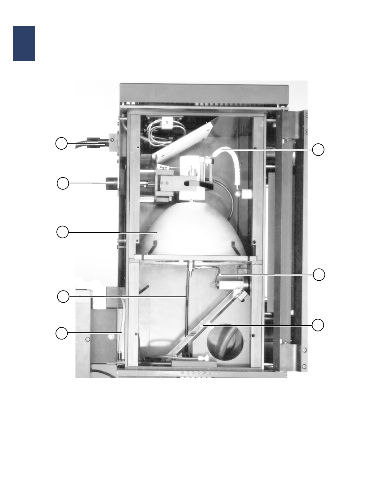
MAINTENANCE
42
OP MA6-8/BA6-8 E Rev05 07-06 Maintenance
2
2.3.2.1. Interior of the Lamp House
LH1000
1 Microscope illumination, fiber optics
2 Ellipsoidal mirror
3 Nitrogen supply tubing
4 Shutter (not visible)
5 Connecting cable, cathode (-) of exposure lamp
6 Connecting cable, anode (+) of exposure lamp
7 Cold light mirror
8 Adjustment knobs for position of exposure lamp
(X,Y,Z)
5
1
2
3
4
7
6
8
Page 51
MAINTENANCE
OP MA6-8/BA6-8 E Rev05 07-06 Maintenance 43
2
2.4. Replacement of the Exposure Lamp 1000 W
See also Chapter 1: Warnings and Safety , section
„Chemical Hazards“.
Danger!
UV lamps are pressurized and contain
mercury.
If handled careless the lamp may ex-
plode emitting shivers and spilling the
mercury.
Store lamps always in the original box.
Handle lamps only with protective gog-
gles or face shield and gloves.
Let the lamp cool down after use.
See the safety section of this manual
for a more detailed description of ade
-
quate lamp handling.
Do not touch the quartz bulb of the ex-
posure lamp or cold light mirror with
your fingers. Clean inadvertently
touched spots immediately with alco
-
hol and a soft lint-free cloth.
2.4.1. Replacement Procedure
• Switch off the mask aligner by main switch.
• If the exposure lamp power supply CIC is sepa-
rately supplied, switch it off, too.
• Do not open the lamp house until the lamp has
been switched off for at least 20 minutes.
• Unscrew the screws securing the door of the
lamp house and swing it open.
• Protect the cold light mirror with lint-free tissue.
• Disconnect the lead wire of the exposure lamp
(remove corresponding unit securing the positive
terminal of the lead wire) and remove.
• Loosen lever holding the upper socket of the ex-
posure lamp and remove lamp from the lamp
house.
Warning!
Handle the lamp only by its metal ends.
Do not mechanically stress the lamp
during installation, the glass bulb could
break or explode.
• Take the new lamp from its box and remove the
knurled nuts, which are no longer needed. If they
are used, they may intercept light from the ellip
soidal mirror, causing a loss of uniformity and
overheating of the lamp.
• Install the negative terminal (non-engraved end)
of the new lamp in the socket on top of the lamp
house (using the adapter if required ), by grasping
the lamp at the positive terminal (engraved end)
of the lamp.
• Connect the lead wire (positive terminal) and
guarantee a well conducting electrical contact
without cracking the lamp or the feed through.
Never twist the body of the lamp or of the feed
through. Counterold directly besides the nut.Re
-
place parts with worn-out electric contacts.
• Close the lamp house and secure it with three
screws.
• Pack the used lamp carefully to the original box
for save storage or disposal.
2.4.2. Adjusting the Exposure
Lamp
All exposure lamp adjustments are done with the exposure lamp power supply in idle mode.
In order to perform the adjustments, you will need an
intensity meter and the appropriate op tica l pro b es
for the wavelength 405 nm, 365 nm, 320 nm, 240
nm, or 220 nm.
WARNING!
The UV and IR radiation produced by
the exposure lamp can cause eye dam
-
age and skin burns.
Personnel entrusted with the adjust-
ment of the exposure lamp should wear
eye and skin protection against ultravi
olet radiation and should avoid extensive exposure.
SUSS MicroTec will not be responsible
for injuries arising from incorrect or un
protected work with these systems.
• Switch ON the mask aligner main switch.
• Switch ON the nitrogen and compressed air
sources which provide cooling for the lamp
house. Check for correct settings of cooling
pressure at the bottom pressure meter if neces
-
sary. Adjust the corresponding regula tor to the
Page 52
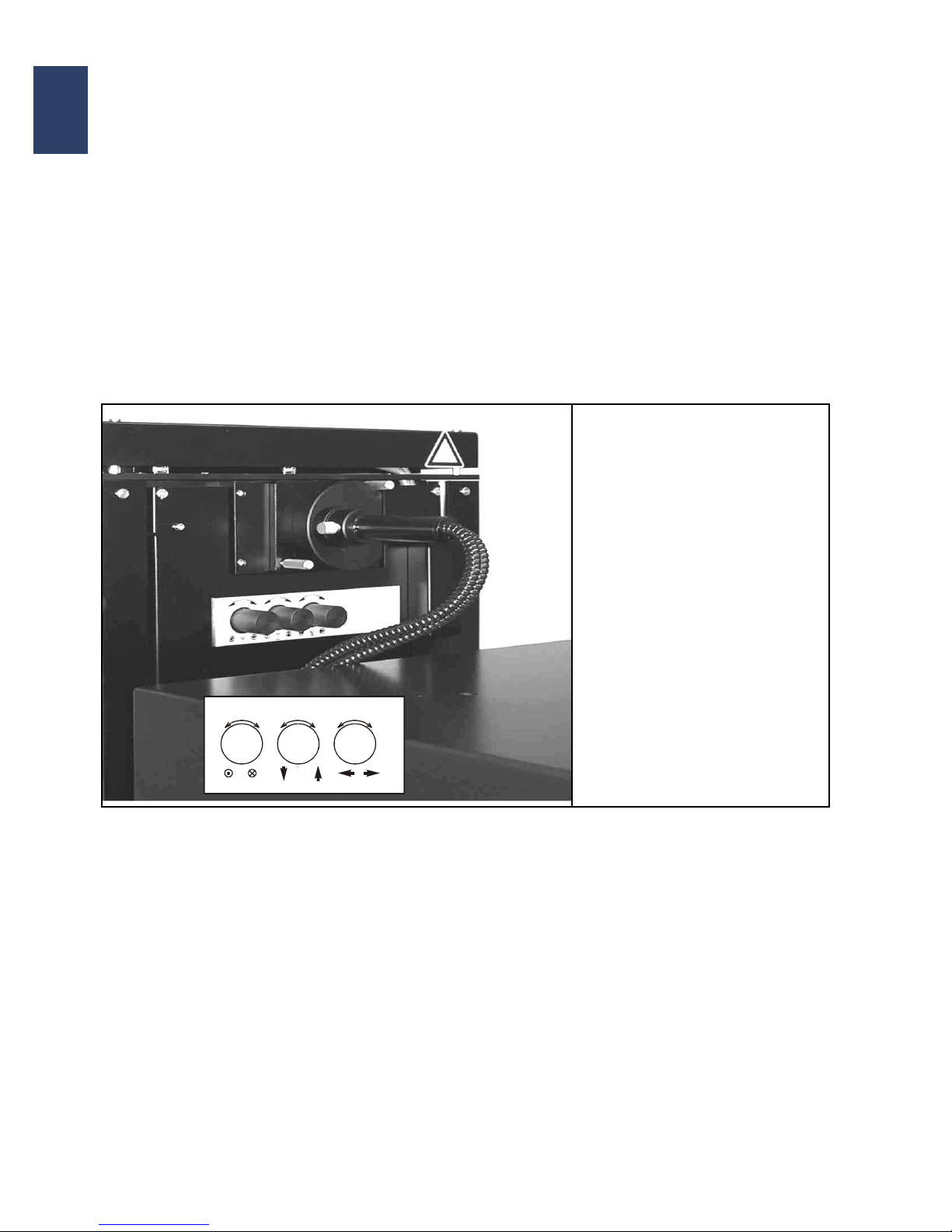
MAINTENANCE
44
OP MA6-8/BA6-8 E Rev05 07-06 Maintenance
2
proper setting.( see section Utilites and Lamp
Cooling).
• Switch ON the exposure lamp power supply CIC
and check that the correct lamp type is selected.
If not, change to correct type.
• Reset the lamp life time counter for the new lamp
(see CIC manual for details).
• Press CP at the CIC.
• Ignite the exposure lamp by pressing the START
button. Allow the lamp to stabilize for at least 15
minutes.
• Start the mask aligner.
• Complete the LOGIN procedure.
• Load the LIGHT MEASURE program (button
LAMPTEST).
• Place a measuring plate instead of the exposure
chuck to avoid scratching of the surface. Place
the optical probe on the plate.
The three lamp adjustment knobs X, Y, and Z on the
lamp house are used to adjust the position of the ex
posure lamp in the ellipsoidal mirror. Their main purpose is to achieve an uniform light distribution over
the given exposure area
2.4.2.1. Adjustment Procedure
• Maximize the respective readings on the power
meter by first shifting the lamp in the Z-direction
and then in the X- and Y-direction.
• Placing the probe alternately at the right and left
hand edges of the illuminated area, use the Xknob to shift the lamp into the corresponding di
rection until the meter gives the same reading at
both locations.
• Placing the probe alternately at the front and rear
edges of the illuminated area, use the Y-knob to
shift the lamp into the corresponding direction un
til the meter gives the same reading at both locations.
• Re ch e ck the po sitio n of the ve rt ical adjustment
knob (Z-knob).
NOTE:
The Z-knob must only be used to maximize the intensity of the exposure lamp. If you wish to adjust the
intensity for process purposes, either adjust the
power supply output or use proper filters. Using the
Z-knob to decrease the intensity will result in a buildup of excess heat in the lamp house which could
lead to lamp explosion. In order to achieve the best
position for an even distribution of light, the Z-knob
must not be readjusted from its maximum intensity
position more than one half turn.
Z-knob: shifts the lamp vertically
and thus primarily controls
the light intensity.
Y-knob:shifts the lamp in the Y-
direction.
X-knob: shifts the lamp in the X-
direction.
Y Z X
Page 53
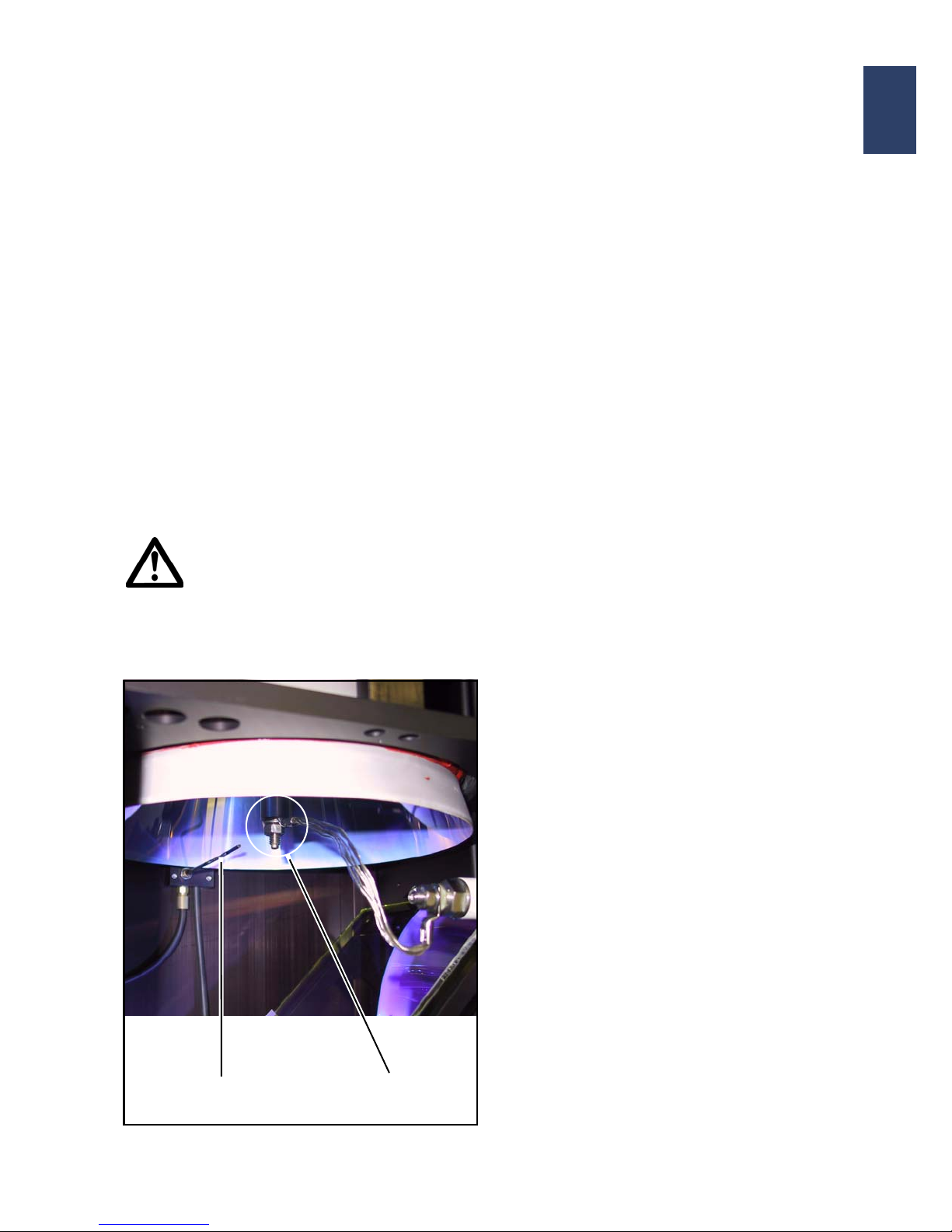
MAINTENANCE
OP MA6-8/BA6-8 E Rev05 07-06 Maintenance 45
2
2.4.3. N2-Control
Cooling of lamp sockets is adjusted by two pressure
valves 11/R5.X (X= 2 and 5), one for each lamp
socket (in LH1500). The pressure for the lower sock
-
et is continuously monitored by the pressure meter
11/C4.
• The adjustment of the N2 pressure valves has to
be done following any part exchange in the cool
-
ing system.
• Only qualified service personnel is allowed to
perform the adjustment. For details see sections:
Working with the Mask Aligner in Chapter 1 and
Utilities in Chapter 2.
• The setting must be completed prior to starting a
lamp. Otherwise there is a risk of lamp explosion.
Caution!
Whenever the ellipsoid mirror or the
coldlight mirror has to be exchanged
be sure to readjust the N2-cooling
nozzle (see fig. below) to cool the lower
lamp socket. Otherwise there is a risk
of lamp explosion.
2.4.4. Exhaust Flow Control
(in Lamp house Intake Tube)
The exhaust flow must be adjusted on site during
machine installation using the factory exhaust sys
tem.
The settings must follow the data given in section
Utilites and Lamp Cooling.
After final completion of settings, the flow sensor
(which is optional and is - if installed - located in the
lam house air intake bottom tube) can be checked
and readjusted:
• Turn the setting screw in the sensor to the switch-
ing point (indication red/green); then turn back to
green by a half rotation.
2.4.5. Use of Other Lamps
Smaller lamps (550W, 350W) can be used in the
lamp house 1000/1500W if special adapters for the
lamp and for socket cooling are installed.
For required parts and cooling specifications ask
SUSS Service.
2.4.6. Lamp House 350W and
350W Lamp Replacement
The small lamp house differs to the lamp house 100/
1500W in some respect:
• It has no access door on the side, it can be
opened only by tilting the head (the upper part) of
the lamp house. The head is secured to the bot
-
tom segment by a screw with access from top
• It has no interlock to the lamp power supply. Be-
fore opening the 350W lamp house, the lamp
power supply and the machine must always be
switched OFF! Respect the warning labels at
-
tached to the lamp house!
• In standard configuration it does not need ex-
haust for additional cooling or ozone reduction.
Forced N2 socket cooling together with natural
air convection is sufficient to cool the 350W lamp.
The glass bulb of the 350W OSRAM HBO lamp
is especially equipped to minimize deep UV radi
-
ation, resulting in very low ozone generation.
• Basic equipment is the 350W lamp.
Potential other lamps are: 200W or 500W. The
200W lamp requires a special lamp socket adapt
-
N2-Cooling Nozzle Lamp Socket
Page 54
MAINTENANCE
46
OP MA6-8/BA6-8 E Rev05 07-06 Maintenance
2
er. The 500W lamp requires removal of the standard 350W socket holder, exchange of socket
cooling nozzles (for both sockets) and installation
of an exhaust tube at the lower part of the lamp
house.
See section lamp cooling in Installation for detailed requirements.
Refitting to 500W must be done by a trained
SUSS technician only.
Warning!
Electric hazards and very intense light
present in the lamp house 350W.
Never open the 350W lamp house when
the machine is still switched on!
Regular lamp replacement in the 350W lamp house
is comparable to replacement in lamp house 100/
1500W:
• See all warnings above and in the chapter Warnings.
• Switch off the main switch.
• Wait until the lamp has cooled down.
• Get access to the lamp house by dismantling the
heat protection covers at the sides of the lamp
house.
• Unscrew the securing screws on top of the lamp
house, and tilt the upper part open.
• Be very careful in handling the lamp and the mirrors.
• Disconnect the wire on the lower lamp socket.
• Unscrew the lamp from the lamp holder and remove lamp.
• Take the new lamp from its box, detach the nuts
and screw the lamp to the lamp holder - observ
ing polarity (negative end in the holder for all
lamps except 500W deppUV - UXM510MD).
• Fasten the lamp to the holder only hand-screwed
• Re-connect the positive terminal wire - if signs of
degradation are visible, replace such electrical
connection parts.
• Check function of the socket cooling nozzle
• Close the lamp house and secure it with the top
screw.
• Re-install the heat portection covers at the lamp
house.
2.5. Replacement of the
Microscope Lamp
Depending on the type of lamp house the halogen
lamp for microscope illumination is located
• in front top of the lamp house 1000W, where
the glass fibre light guide is connected or
• in an extra lamp box located on back of the
lamp house 350W
The replacement procedure is the same for both locations:
Exchange of the lamp:
• Loosen the two knurled screws of the lamp holder and pull out the holder carefully.
• Plug off the connection cable of the lamp.
• Loosen the lamp clamping on the holder and remove the lamp.
• Insert new lamp and re-insert holder plate.
Caution!
The illumination lamp could be very hot
after use.
Let the lamp cool down for some min-
utes. Switch off the main switch of the
machine or disconnect at least the lamp
supply unit during lamp exchange.
Replace always by identical lamp type.
Watch for intense light near to the lamp,
as well
as at the output of the fiber optic
cable!
This could harm your eyes!
Page 55
MAINTENANCE
OP MA6-8/BA6-8 E Rev05 07-06 Maintenance 47
2
2.6. Cleaning of Optical
Components
Whenever the resolution worsens significantly - resulting on a blurred or obstructed image - or if light
intensity decreases, or if visible contamination is to
be seen on the optical components - including a
translucent film on mirrors, the optical surfaces
should be cleaned.
Deposition on optical surfaces can happen and may
be caused by impurity of gaseous media or by pro
cess solvents or other process related contamination. Depending on the type of deposition it could be
blown off dry or washed off by an appropriate solu
tion.
Be very gentle in cleaning because most optical
parts (mirrors, lenses) have high grade coating.
Caution!
High grade optical surfaces are a deter-
mining factor for image quality.
When cleaning any optical surface, the
surface quality could be damaged
heavily if improper method or material
is used.
Do not touch optical surfaces with
rough material or with bare skin!
Use only solvents and methods as recommended below. NEVER use aggressive solvents like acetone.
Never soak optical components in solvents for an extended time. Adhesive
compounds could be dissolved and
coatings could be destroyed.
Warning!
Isopropyl alcohol (IPA), Petroleum
Ether and many other solvents are
highly flammable.
Use of such solvents is only allowed in
a well-ventilated area, with ignition
sources removed.
Moreover, also cloth soaked with flammable solvent has a potential for selfignition.
Deposit used soaked tissues according
to local safety regulations.
Use of flammable solvents is restricted
to adequately trained personnel.
Warnings of the MSDS (Material Safety
Data Sheet) must be understand and re
-
spected.
Page 56

MAINTENANCE
48
OP MA6-8/BA6-8 E Rev05 07-06 Maintenance
2
2.6.1. Cleaning Materials
• Latex laboratory gloves:
Protective gloves should always be used, whenever solvents are applied. Moreover, use of
gloves will prevent direct touching of optical com
ponents, which would result in new contamination.
• Dry cleaning:
To blow off dust, use only filtered, dry nitrogen
gas, applied through an anti-static nozzle. If nitro
gen is not available, use extremely clean compressed air (CDA).
• Flushing:
For final flushing after wet removal of deposits,
apply always DI-water. It removes also smears
produced by solvents. Remaining water droplets
can be removed without residue by a nitrogen
blow.
• Detergent solution:
A mild soap, e.g. dish washing liquid in a 1% dilution with DI-water, is likewise appropriate. Perfumed, alkaline or colored dish washing products
are to be avoided.
• Solvent:
Isopropyl alcohol (IPA) is acceptable as a solvent.Never use acetone to clean the optical surfaces. They could be dissolved and destroyed.
For obstinate contaminations (e.g. resin) Petroleum Ether (30/40) can be used.
Note:
This special light benzine can be supplied by
chemical suppliers as Carl Roth (www.carlroth.de)
Attend the much higher flammability compared to
ordinary gasoline!
• Cloth:
Avoid wiping with cloth, because any wiping can
cause fine scratches in optical coatings.
If unavoidable for removing of persistent contaminations use only dust- and lint-free tissues, such
as lens cleaning tissues or equivalent. Soak the
tissue with solvent and apply only by wiping with
a gentle, figure eight motion or by dipping off gen
tly.
For removal of small local contamination spots as
well as for wiping very small lenses the lens tis
-
sue should be twisted around a swab.
Do not use any plastic cloths or plastic swab
stems for cleaning. Plastics could be dissolved
by alcohol and produce a smear coating on the
optical components.
2.6.2. Application Technique
Preparation for cleaning of optical components:
• Provide a clean laboratory table
• Have nitrogen blower with antistatic nozzle
• Prepare wash bottles with DI-water, detergent
solution and solvent, and empty bowls for collect
-
ing the liquids.
• Prepare submersion bowls filled with DI-water,
detergent solution and solvent.
• Supply gentle, clean cloths as described above.
• Prepare a box with a lid for safe collection of solvent soaked cloths (to prevent from self ignition).
2.6.3. Cleaning Procedure
Remove the optical component, which has to be
cleaned, from the machine and note the orientation
and exact location for later reinstallation.
Wet cleaning can be done - as appropriate - by rinsing of the liquid over the optical surface or by submersion of the optical component into the clean
liquid.
Fingerprints or droplets of oil should be removed - as
soon as they appear - in soap water.
See the flow diagram below for detailed cleaning
procedure recommendation. In case of doubt about
adequate clening call SUSS service in advance.
Note:
Solvent consuption should be kept to a reasona ble
minimum for environmental and safety reasons.
Page 57
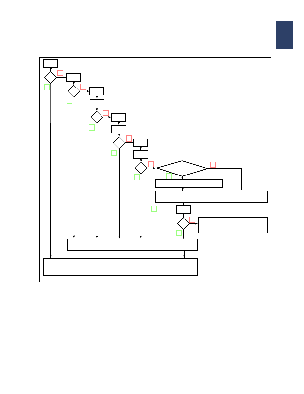
MAINTENANCE
OP MA6-8/BA6-8 E Rev05 07-06 Maintenance 49
2
Legend to the cleaning procedure diagram:
N2 - blow off dust (or droplets) with nitrogen
y/n - check, if surface is clean (y=yes/clean;
n=no/no success)
DI - rinse with DI-water or submerge to DI-
water (as appropriate for the component.
Soap - rinse or submerge with detergent (1%) in
DI-water.
IPA - rinse or submerge with isop ropanol alcohol
PE - Petroleum ether (special light benzine)
For extremely obstinate contaminations petroleum
ether can be used in addition to IPA.
If a treatment step has been nearly successful, but
one cannot be satisfied completely by the result, re
peat this step, prior to trying the next treatment step
or solvent type.
When a cleaning procedure proved to be succe ssful
at an individual machine or production line, use al
ways the same procedure and solvent when the optics of the identical machine needs cleaning again.
N
2
DI
Soap
n
?
?
n
DI
?
IPA
DI
?
n
n
Coated
Optics
Proceed exremely gently
Wipe carefully with soaked clean tissue (see text)
use the liquid, which proved most effective before
PE
DI
?
n
DI
?
n
Exchange component or
call for SUSS Service
N2 - Blow completely dry with clean Nitrogen
Reinstall the optical component
y
y
y
y
y
y
y
y
n
(attend location and orientation)
Page 58
MAINTENANCE
50
OP MA6-8/BA6-8 E Rev05 07-06 Maintenance
2
2.6.4. Safe Clean-up after Use of
Solvents
• Do not mix different liquids.
• Cap each bin (bottle, bowl, can) securely.
• Restore all unused inventory to its safe-keeping.
• Dispose each used cleaning liquid according to
company or local waste rules and regulations.
• Dispose soaked cloths accordingly.
2.6.5. Removal and Re-Insertion
of Specific Optical Compo
-
nents
2.6.5.1. Handling of the Coldlight
Mirror
In order to be able to clean the coldlight mirror properly, it must be removed from the lamp house.
Caution!
The coldlight mirror must be treated
with the utmost care!
The orientation (coated face) of the coldlight mirror
in the holder is critical if the mirror is marked at the
side rim by an arrow. The tip of the arrow must be
oriented to the lamp, because this is the coated face.
When installing the mirror, make sure that the coat
ed side is oriented toward the exposure lamp.
New mirrors without an arrow at the rim are coated
on both faces (in doubt, check for identical reflection
of both faces).
The brackets for holding the coldlight mirror should
be tightened not too tightly in order to enable a ther
-
mal expansion of the mirror during operation.
Warning!
Do not touch the UV-lamp or the N2-
cooling nozzle, when removing or installing the coldlight mirror. The lamp
could be destroyed or lamp cooling
could be affected.
For detailed advice see manual sections Lamp Exchange, Lamp Cooling
and N2-Control!
Danger!
Special care is required at the lamp
house 5000W, see resp. manual.
2.6.5.2. Handling of the Ellipsoid Mirror
For removal and installation of the ellipsoid mirror
the UV lamp must be detached.
Warning!
For safe lamp handling insstruction see
manual section lamp exchange, lamp
cooling and N
2
-Control!
Do not deadjust N2-cooling nozzle!
To move out the mirror suport frame (in
the 350W lamp house the mirror itself)
the retaining screws must be removed.
Treat the reflecting surface with utmost
care!
In reassembly watch for centering the
mirror.
2.6.5.3. Lamp House Adjustments
The replacement and installation of the exposure
lamp is described in the operator manual of the
mask aligner.
The setting of the lamp, lamp house and socket cooling is also described in the operator manual of the
mask aligner. There you will also find a list of the
cooling data, related to the lamp type used.
2.6.5.4. Adjustment of the Optics
The description of the optical components and their
exact position are found in the operato r manu a l of
the mask aligner.
The optical components are positioned in the beam
path so that the uniformity and intensity are optimally
set in the exposure plane. This adjustment is set in
the factory and should only be changed on site and
readjusted if necessary by a SUSS MircoTec service
technician.
Page 59

MAINTENANCE
OP MA6-8/BA6-8 E Rev05 07-06 Maintenance 51
2
2.6.6. Conclusion
Remarks for the Optics Cleaning
1 Use clean, dry nitrogen as a first step to remove
dust or particles.
2. Never wipe lenses with dry paper or tissue - th is
may cause scratches.
3. Never use abbrasive materials, e.g. dry leather
wipers or dry cloths or polystyrene rods.
4. Always try Di-water for cleaning before using a
solvent.
5. Never use acetone to clean any optical surface.
It could be dissolved and destroyed. Never use
acids or ammoniac for cleaning. Use only above
recommended solvents.
6. Never use „Throw-away“ Q-tips because they
contain contaminations.
7. Never use metal swabs you could scratch the optical surface.
8. Never try to disassemble combined optics and
the inner optics of the microscopes.
9. Never soak optical components in solvents for an
extended time.
2.7. Facts and Data for
Maintenance and Service
2.7.1. Consumables
• The UV-lamp must be replaced, when it reaches
the operation life time, as specified by the lamp
manufacturer. (see section Lamp Repla ce me n t
for details). Note that this time interval is speci
-
fied for both features:
• save lamp use with minimum risk of lamp explosion, and
• intensity degradation within specified limit
(mostly within 70% of original intensity). The
specified time applies only for continuous use
time with rare ignition events.
If burning times are short and the lamp is ignited
very often, the life time can be reduced to 50%. If
a lamp is used outside its specification for cooling
or the electric parameters, the time could be re
-
duced dramatically !
• The electric connection wire of the lamp (anode
wire) - and assembling materials like nuts - must
be replaced, as soon as the surface of the con
tact points degrades and is no more perfectly
conductive.
• The halogen microscope illumination lamp must
be replaced when it has burned out (many
1000h). Replace only by the identical type.
• Vacuum seals on chucks or mask holders are
sensitive and may be destroyed by fragments or
by inadequate use. They must be replaced im
-
mediately when leaking.
• Contamination and degradation of photo masks
depends highly on the exposure/contact modes
used in different applications.
Required cleaning or replacement intervalls must
be tested by the user. SUSS does not supply
photo masks.
• The elipsoid mirror has - because of its sensitive
coating - a limited life time; generally it must be
replaced after 2 to 5 years of use.
• For cleaning purposes solvents and tissues are
required as described in the appropriate sections
of the manuals.
Page 60

MAINTENANCE
52
OP MA6-8/BA6-8 E Rev05 07-06 Maintenance
2
2.7.2. Hazardous Materials and
Solid Waste
Potentially hazardous materials used at the
machine are (see also the Hazard Warning Section
of this manual for more detailed description as well
as for safety measures - especially the subsections
Chemical Hazards and Mechanical Hazards):
• The UV lamp, which contains toxic Mercury (spill-
ing at glass breakage), which is highly pressurized when hot, and which is extremely hot during
lighting and for some time after switching off.
• Process materials - if toxic - classification of toxic
material for his personnel is the responsibility of
the user.
• Sharp broken fragments of process material.
• Liquid cleaning agents including used solvents
and soaked tissues.
Solid waste resulting from machine use are:
• The UV lamp (containing mercury and to be dis-
posed as special waste according to local regulations)
• the Halogen lamp,
• Cle an in g ma te ria l (re fe r to th e ap pr o pri at e sec-
tion in this manual for more details).
2.7.3. Service Exchange of Heavy
Subassemblies
The following subassemblies have been identified
for special handling requirements, and must be dis
mounted, mounted and transported only by 2 persons:
• TSA (top side microscope), weighting 20 - 22 kg
(6” or 8”);
• Lamp supply CIC1200, weighting 20 kg
• co m pu te r un it, weigh tin g 28 kg.
2.7.4. Supplier’s Contact
See the last page of manuals (resp. last cover page
of printed folders) for a list of SUSS units and r epre
sentatives wordwide - valid at the time of manual
publication.
For the latest contact list go to www.suss.com !
Page 61
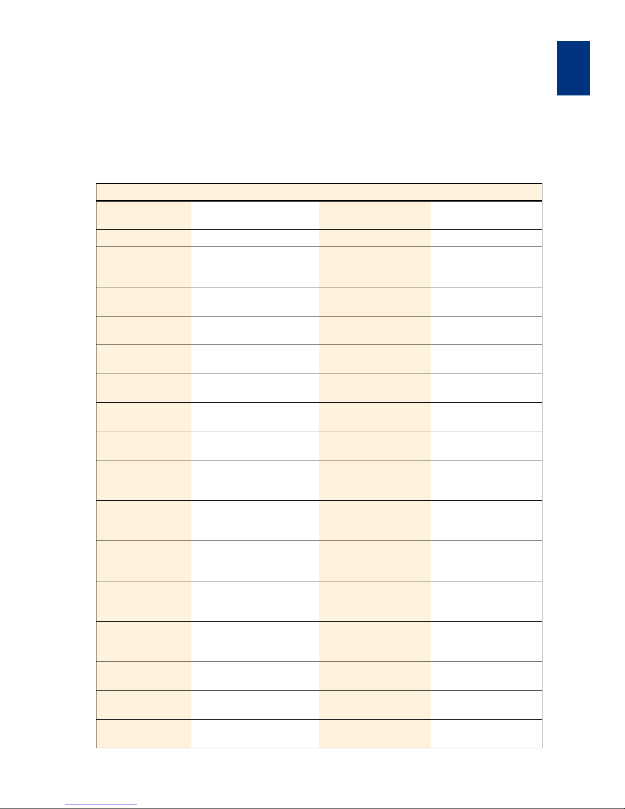
Appendix
MA6 / MA8 - 3 Appendix - Rev.05 07-06
53
3
3 APPENDIX
3.1 Parameter Ranges and Default Settings
The table shows the range of values for parameters included in the main processes exposure and bonding.
Parameter Description Default value Range of Values
Expose Type Type of exposure Soft [Soft, Hard, Low Vac,
Vac, Prox, Flood-E]
Exp. Time Time of exposure 5.0 sec. [0.1...999.9]
Wait Time Pause between the expose
cycles, using Multiple Expo
-
sure
10 sec. [1...999,9]
Exp. Cycles No. of cycles, using Multiple
Exposure
3 [1...500]
Al. Gap Alignment distance during
the alignment
100 µm [10...300]
Exp. Gap Distance during the expos-
ure in proximity
50 µm [0...300]
HC-Wait Time Time for N2 purge under the
wafer prior exposure
4 sec. [0...30]
Pre Vac Time of the pre-vacuum with
reduced vacuum pressure
4 sec. [0...30]
Full Vac Time with full vacuum before
exposing in vacuum contact
4 sec. [0...30]
Vac Purge N2 purge time into the
vacuum chamber after
exposure
4 sec. [0...30]
N2 Purge Time
1
N2 purge time before exposure for exposing in N2
atmosphere
4 sec. [0...999]
N2 Purge Gap
1
Gap distance during N2
Purge for exposing in N
2
atmosphere
30 µm [0...1000]
WEC-Offset Substrate position optional
different to contact- respec
-
tively to 0-position
0 µm [+/- 50]
WEC Type Type of the Wedge Error
Compensation
Cont [Cont / Spacer /
GlobCont 2 /
GlobSpac 2]
WEC delay Time to get parallelism bet-
ween substrate and mask
1 sec. [0,1...120]
Spacer Thick Thickness of the spacers MA = 2000
BA = 100 µm
[50, 100, 125, 200,
1000, 2000]
Substrate Thick Thickness of substrate using
global WEC
500 µm [10...3000]
Page 62
Appendix
MA6 / MA8 - 3 Appendix - Rev.05 07-06
3
54
Load Type Load type of substrate(s) Slide [Slide / Fixture]
Unload Type Unload type of the sub-
strate(s)
Slide [Slide / Fixture]
Clamp Clamping of the substrates
with or without spacers in
between
with Spacers [with Spacers, without
Spacers]
Lower Sub. Lower substrate is opaque
or transparent
Glass [Glass / Silicon]
Upper Sub. Thick 2Thickness of the upper sub-
strate
500 µm [0...2000]
Lower Sub. Thick 2Thickness of the lower sub-
strate
500 µm [0...2000]
1
These parameters are only available with special optional hard- and software.
2
These parameters are only available after activating the FUNCTION UNI-Bond.
Parameter Description Default value Range of Values
Page 63

Appendix
MA6 / MA8 - 3 Appendix - Rev.05 07-06
55
3
3.2 List of Abbreviations
Θ Theta rotation
Al. Gap Alignment gap
AL400 Large gap alignment system
BA Bond aligner
BSA Bottom side alignment
BsSubPx WEC with spacers beside substrate
CIC Constant intensity controller
Cont Contact
DIP Mikro switch at microcontroller card
DVCU Digital video control unit
E Error message
Exp. Exposure
Exp. T. Exposure time
Flood-E Exposure type: flood exposure(without mask)
F-WEC Force-sensor WEC
GlobCont Global WEC, contact mode
GlobSpac Global WEC, spacer mode
GWEC Global wedge error compensation
Hard Exposure type: hard contact
Hard Ct Exposure type: hard contact
HC Wait T. Hard contact wait time
IR InfraRed
ISA Inter substrate alignment
L:F Load the substrate by fixture
L:S Load the substrate by slide
LED Light emitting diode
Low Vac Exposure type: low vacuum contact
Lvac-Ct Exposure type: low vacuum contact
M.Pin Middle pin
MA Mask aligner
Mholder Mask holder
Page 64

Appendix
MA6 / MA8 - 3 Appendix - Rev.05 07-06
3
56
N2 Nitrogen
NFH Near field holography
P Purge (nitrogen)
Pgm. Program
Pre. Vac Pre vacuum
Prox Exposure type: proximity
S Substrate (square or irregular shape)
SBSA Single bottom side alignment
Soft Exposure type: soft contact
Soft-Ct Exposure type: soft contact
STG stage
SW software
TH Theta
Tri- B Triple stack bonding
TSA Top side alignment
Typ e A A type of chuck for anodic bonding
Typ e B A type of chuck for silicon to silicon pre bonding
U:F Unload substrate by fixture
U:S Unload substrate by slide
Vac Exposure type: vacuum contact
Vac -Ct Exposure type: vacuum contact
W Round wafer
WEC Wedge error compensation
Xl, Xr X-coordinate, left/right objective
Yl, Yr Y-coordinate, left/right objective
Z position of substrate/wafer relative to mask 0 means contact
Page 65

Appendix
MA6 / MA8 - 3 Appendix - Rev.05 07-06
57
3
3.3 Spare Parts Llist (Extract)
167330 SUSS MA6/BA6 MASK- UND BONDALIGNER STANDARD
106969 ALIGNMENT STAGE MA6/BA6
111609 Z-STROKE MA6/BA6
130727 SPINDLE
158792 COMBINATION MOTOR 3557 + ALTERNATOR HEDS 5500 A+CABLE
144845 TOOTHED BELT T 2,5 Z 152 B 6 L 380
111654 WEDGE ERROR COMPENSATION HEAD MA4/6-BSA
124500 GLAS CYLINDER DIA12
152106 O Ring NBR 769-9x1,5
152192 O Ring NBR 769-127x2
152168 O Ring NBR 769-110x2
152254 O Ring NBR 769-95x2
130086 COMPRESSION SPRING
125370 BRAKE SCREW
153042 GROOVED BALL BEARING
172959 TENSION SPRING
150896 L SWIVEL CONNECTION M5 FOR HOSE 5X1
152095 O-RING 015.30X002.40 72 NBR/872
146113 PROXIMITY SWITCH/IND/NPN/7X45
119243 COMPRESSION SPRING
119242 TENSION SPRING 0.5X3X12
150910 L-BANJO L M5 4X1 MOVEABLE BANJO FITTING
150893 DISTRIBUTOR FOR HOSE M5X1
111615 X-Y-Θ-STAGE MA6/BA6
112023 GUIDE LINEAR AXIS ROTATION
149807 PROXIMITY SWITCH/IND/NPN/S/2.0/8X8X20
152438 TENSION SPRING
149807 PROXIMITY SWITCH/IND/NPN/S/2.0/8X8X20
158792 COMBINATION MOTOR 3557+ALTERNATOR HEDS 5500 A +CABLE
112011 STAGE CASING MA6/BA6
144859 MICROMETER SCREW, 20MM, ADJUSTMENT X-Y-TRAVEL
143761 MICROMETER SCREW, 25MM, ADJUSTMENT ROTATION
144169 COUPLING MASTER SELFSEALING RED M5 R1/8"
150909 L-SWIVEL CONNECTION M5 FOR HOSE 4X1
150896 L SWIVEL CONNECTION M5 FOR HOSE 5X1
150922 SCREWED PLUG CONNECTION FOR HOSE 4X1
150893 DISTRIBUTOR FOR HOSE M5X1
150910 L-BANJO L M5 4X1 MOVEABLE BANJO FITTING
150892 CONNECTION M5 SW7 L11.5
150906 L-CONNECTION
Page 66

Appendix
MA6 / MA8 - 3 Appendix - Rev.05 07-06
3
58
149762 PROXIMITY SWITCH/IND/PNP/S/0.6/3X22/LED
111650 TRANSPORT SLIDER MA6/BA6
134111 CYLINDER
150899 REDUCING NIPPLE R 1/8" M5 SW 14
150892 CONNECTION M5 SW7 L11.5
150897 L-SWIVEL CONNECTION M5 7X11.5X11
150894 HOSE COUPLING M5 FOR HOSE 5X1
146062 PROXIMITY SWITCH/IND/NPN/S/1.5/8X8X40
129890 RUBBER LIP MA4-III
150893 DISTRIBUTOR FOR HOSE M5X1
112021 HOSE REEL FOR MA6/BA6 CHUCK STAGE
150908 HOSE PVC DIM.3/5/1
112026 SENSOR X-Y-Q-STAGE
146062 PROXIMITY SWITCH/IND/NPN/S/1.5/8X8X40
150896 L SWIVEL CONNECTION M5 FOR HOSE 5X1
169609 BASIC ASSEMBLY MA6/BA6 CPL. BASE PLATE 40MM
108347 PNEUMATIC BLOCK MA6/BA6
150906 L-CONNECTION
150920 SOLENOID VALVE NW1/8BAR/24V 65.127
150940 THROTTLE VALVE M5 SW12
150921 THROTTLE-BACK-PRESSURE VALVE 0.5BAR 10X20X22
151085 PRESSURE REGULATOR O-21 BAR
151203 PRESSURE SWITCH TYPE UPS-1K
150892 CONNECTION M5 SW7 L11.5
150903 CONNECTION COUPLING M5 SW7 LG10
150895 T-SWIVEL CONNECTION M5 14X7X11.5
150897 L-SWIVEL CONNECTION M5 7X11.5X11
150914 T-SWIVEL CONNECTION M5 FOR HOSE 4X1
150922 SCREWED PLUG CONNECTION FOR HOSE 4X1
150894 HOSE COUPLING M5 FOR HOSE 5X1
150926 T-FITTING 52.050
151024 CROSS PLUG CONNECTION M4 FOR HOSE 4X1
150947 L-PLUG CONNECTION 2X FOR HOSE 4X1
150902 DOUBLE NIPPLE MALE/MALE
150930 T-CONNECTION 3XM5 12X14X8
150907 HOSE 4X0.65 POLYAMIDE
111675 FRONT PANEL RIGHT
135073 MANOMETER 1-0BAR
135072 MANOMETER 0 -1 BAR
160967 MANOMETER 0 -4 BAR
160966 MANOMETER 0 -10BAR
Page 67

Appendix
MA6 / MA8 - 3 Appendix - Rev.05 07-06
59
3
151430 PRESSURE REGULATOR 0-1 BAR
162324 POTENTIOMETER WIRE BOUND 10KOHM
149878 PRECISION POTENTIOMETER 100 KOHM
159913 SWITCH - SPLITFIELD
159914 SWITCH - BSA/IR
159912 SWITCH - MAGNIFICATION BSA
149987 SWITCH - ILLUMINATION - ON/OFF
149988 SWITCH- OPENER
149989 SWITCH - SHUTTER
150906 L-CONNECTION
150940 THROTTLE VALVE M5 SW12
150903 CONNECTION COUPLING M5 SW7 LG10
150922 SCREWED PLUG CONNECTION FOR HOSE 4X1
135069 PRESSURE REGULATOR 0-1 BAR
150937 T-SWIVEL CONNECTION
150914 T-SWIVEL CONNECTION M5 FOR HOSE 4X1
150924 OUTLET RESTRICTOR 47.200
150895 T-SWIVEL CONNECTION M5 14X7X11.5
166666 BASE PLATE CPL. MA6/BA6
149992 MUSHROOM BUTTON WITH KEY
149993 SWITCH
108278 MAINS WIREING MA6/BA6
150068 MAIN SWITCH T3-1-102/EA/SVB-SW
158611 PROTECTIVE CIRCUIT BREAKER PROPAK 4A/250VAC 2POLAR
PHB22-A8-SX-22-H-A-4-2
150906 L-CONNECTION
151107 SCREWED PLUG CONNECTION
150922 SCREWED PLUG CONNECTION FOR HOSE 4X1
150914 T-SWIVEL CONNECTION M5 FOR HOSE 4X1
151089 PNEUMATIC ELECTRONIC SWITCH
150899 REDUCING NIPPLE R 1/8" M5 SW 14
150917 PRESSURE REGULATOR R1/8" 0-7BAR
108277 ELECTRONIC RACK MA6/BA6
113824 PC-BOARD MOTOR CONTROL MA6/BA6
146453 FUSE SLOW BLOW 3.15A DIN 41571
114307 PC-BOARD MICROCONTROLLER 8BIT BANKING
150750 SWITCH
166757 ELECTRONIC MODULE INSERT MA6/BA6
114142 PC-BOARD DISTRIBUTOR PLATE BA6
146453 FUSE SLOW BLOW 3.15A DIN 41571
146876 FUSE SLOW BLOW 2.0A DIN 41571
163001 SPARE PART KIT FOR MASKALIGNER MA6 / MA8 B A6 MJB3
146449 FUSE SLOW BLOW 1A DIN 41571
Page 68

Appendix
MA6 / MA8 - 3 Appendix - Rev.05 07-06
3
60
146876 FUSE SLOW BLOW 2.0A DIN 41571
146453 FUSE SLOW BLOW 3.15A DIN 41571
146455 MICROFUSE 10A SLOW DIN 41571
152100 O-RING 3 X 1
146847 FUSE-SLOW BLOW 1.0A US-N 6.3X32MM
146845 FUSE-SLOW BLOW 5.0A US-N 6.3X32MM
146838 FUSE-SLOW BLOW 0.5A DIN 41571
146837 FUSE-SLOW BLOW 5 A DIN 41571
158036 ADAPTION KIT FOR MASK HOLDER MA6/BA6/M-7
146062 PROXIMITY SWITCH/IND/NPN/S/1.5/8X8X40
107024 TOPSIDE MICROSCOPE STAGE MA6/BA6
111677 MICROSCOPE SUPPORT
151174 FLOWMETER
151130 REDUCING NIPPLE R1/4"/M5
150906 L-CONNECTION
107001 MICROSCOPE MANIPULATOR MA6/BA6
112020 X-Y-TSA-MANIPULATOR
158792 COMBINATION MOTOR 3557+ALTERNATOR HEDS 5500 A +CABLE
114171 AG ELECTRONIC PARTS TSA MIKROSKOP MA6/BA6
113824 PC-BOARD MOTOR CONTROL MA6/BA6
146453 FUSE SLOW BLOW 3.15A DIN 41571
158792 COMBINATION MOTOR 3557+ALTERNATOR HEDS 5500 A+CABLE
143719 RUBBER BUFFER, 55 SHORE A, 2 FEMALE THREADS
145011 COUPLING
146062 PROXIMITY SWITCH/IND/NPN/S/1.5/8X8X40
112025 Z-MOVEMENT MICROSCOPE MA6/BA6
146062 PROXIMITY SWITCH/IND/NPN/S/1.5/8X8X40
150899 REDUCING NIPPLE R 1/8" M5 SW 14
150923 THROTTLE-BACK PRESSURE VALVE M5
151385 PNEUMATIC CYLINDER/PD-63/ST-50/DA/SSC/ CUS
150974 PNEUMATIC CYLINDER/PD-8/ST-25/SA
150918 VALVE M5 SW9 LG21.5 0.5BAR
150922 SCREWED PLUG CONNECTION FOR HOSE 4X1
150937 T-SWIVEL CONNECTION
150939 Y-PLUG DIA 4 F. HOSE 4X1
150945 PLUG CONNECTION 2X FOR HOSE 4X1
157467 CARRIERUNIT MOVABLE LH350/LH1000 MA6/BA 6
111713 HOLDER MIRROR/LAMP HOUSE MA6/BA6
112003 PNEUMATIC TRANSPORT
151317 PNEUMATIC CYLINDER/PD-16/ST-200/DA/CUS
151171 COUPLING FLEXIBLE FK-M 6
150906 L-CONNECTION
Page 69

Appendix
MA6 / MA8 - 3 Appendix - Rev.05 07-06
61
3
150947 L-PLUG CONNECTION 2X FOR HOSE 4X1
150907 HOSE 4X0.65 POLYAMIDE
146113 PROXIMITY SWITCH/IND/NPN/7X45
111006 LIMIT STOP
144277 DAMPING ELEMENT FA 1010 D3 MIRROR HOUSE
111031 MIRROR HOUSE SLIDE
111006 LIMIT STOP
144277 DAMPING ELEMENT FA 1010 D3 MIRROR HOUSE
100480 POSITIONINDICATOR
146062 PROXIMITY SWITCH/IND/NPN/S/1.5/8X8X40
111712 CARRIAGE EXPOSURE UNIT MA6/BA6
146113 PROXIMITY SWITCH/IND/NPN/7X45
151386 PNEUMATIC CYLINDER/PD-20/ST-5/SA/CUS/POS
150906 L-CONNECTION
BOTTOMSIDE MICROSCOPE
112420 MICROSCOPE MANIPULATOR MA6/BA6
159207 MOTORCOMBINATION
146062 PROXIMITY SWITCH/IND/NPN/S/1.5/8X8X40
145033 TOOTHED BELT T 2,032/Z100/B4 L203,2
144804 TOOTHED BELT T 2,032 Z 90 B 4 L 182,88
112318 BSA-MICROSCOPE ILLUMINATION
146066 LAMP 6V/15W
TSA-MICROSCOPE ILLUMINATION
148649 LAMP HALOGEN 13.8V/85W
171554 FAN 12V AC
EXPOSURE OPTIC - ELLIPSOIDAL REFLECTORS
145525 ELLIPSOIDAL REFLECTOR LH350
130415 ELLIPSOIDAL REFLECTOR LH1000
130416 ELLIPSOIDAL REFLECTOR LH1000 - HP
EXPOSURE OPTIC - COLD LIGHT MIRRORS
OPTIK UV250
169678 COLD LIGHT MIRROR UV-250 - LH 350
169724 COLD LIGHT MIRROR UV-250 - LH 1000
OPTIK UV300
172414 COLD LIGHT MIRROR UV 300 - LH 350
172410 COLD LIGHT MIRROR UV 300 - LH 1000
OPTIK UV400
172412 COLD LIGHT MIRROR UV 400 - LH 350
169446 COLD LIGHT MIRROR UV 400 - LH 1000
DIVERSION MIRRORS
124463 DIVERSION MIRROR UV400 - LH 1000
Page 70

Appendix
MA6 / MA8 - 3 Appendix - Rev.05 07-06
3
62
130597 DIVERSION MIRROR UV 400HP
106970 EXPOSURE UNIT MA6/BA6/350W
106538 LAMP HOUSE 350W MA6/BA6
110189 SHUTTER LAMPHOUSE COMPLETE
107022 EXPOSURE UNIT MA6/BA6/1000W
106174 LAMP HOUSE 1000W MA6/BA6
111016 SHUTTER LAMPHOUSE COMPLETE
EXPOSURE LAMPS
146049 LAMP HG-350W/S OSRAM
182538 LAMP USH 350DS USHIO
148979 LAMP HG-XE500W USHIO
148959 LAMP HG-1000W OSRAM
169776 LAMP USH-1000 KS USHIO
Page 71
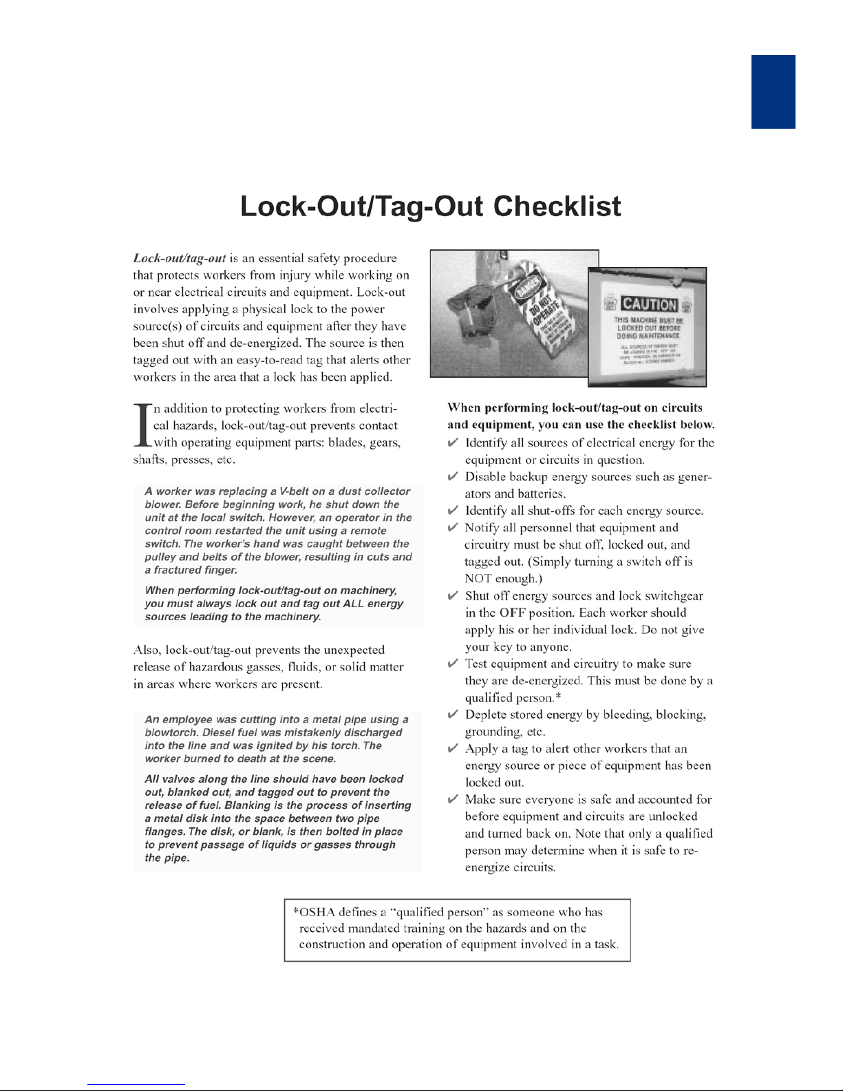
Appendix
MA6 / MA8 - 3 Appendix - Rev.05 07-06
63
3
3.4 Lock-Out / Tag-Out Checklist
Page 72

Appendix
MA6 / MA8 - 3 Appendix - Rev.05 07-06
3
64
Page 73
Appendix
MA6 / MA8 - 3 Appendix - Rev.05 07-06
65
3
3.5 Schematics of the Pneumatic System
Description Schematic Pages
Pneumatic Plan, Rev: 06-G 1 of 8 67
2 of 8 69
3 of 8 71
4 of 8 73
5 of 8 75
6 of 8 77
7 of 8 79
8 of 8 81
Page 74

Appendix
MA6 / MA8 - 3 Appendix - Rev.05 07-06
3
66
Page 75
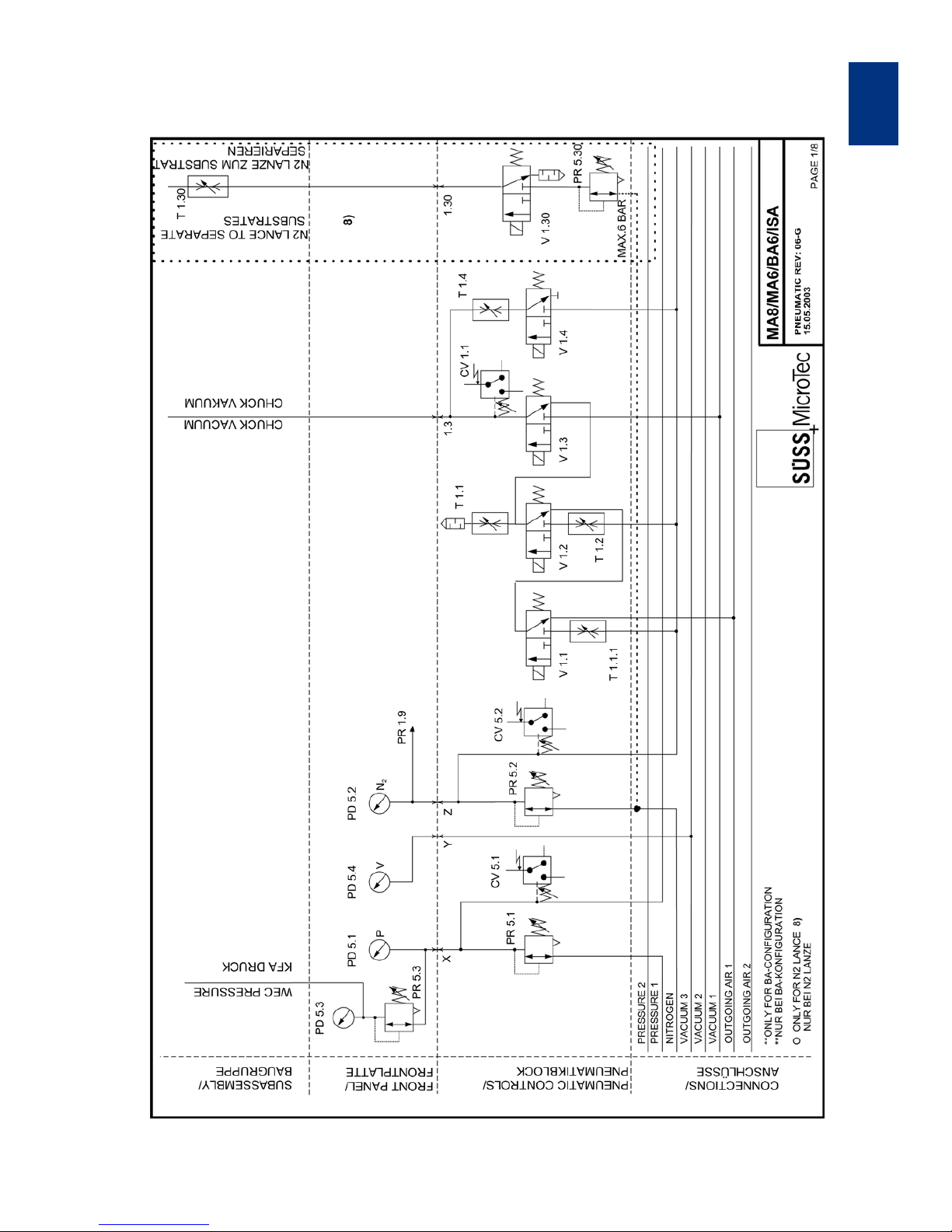
MA6 / MA8 - 3 Appendix - Rev.05 07-06
67
Appendix
3
Pneumatic Plan, Rev: 06-G, Sheet 1 of 8
Page 76

Page 77
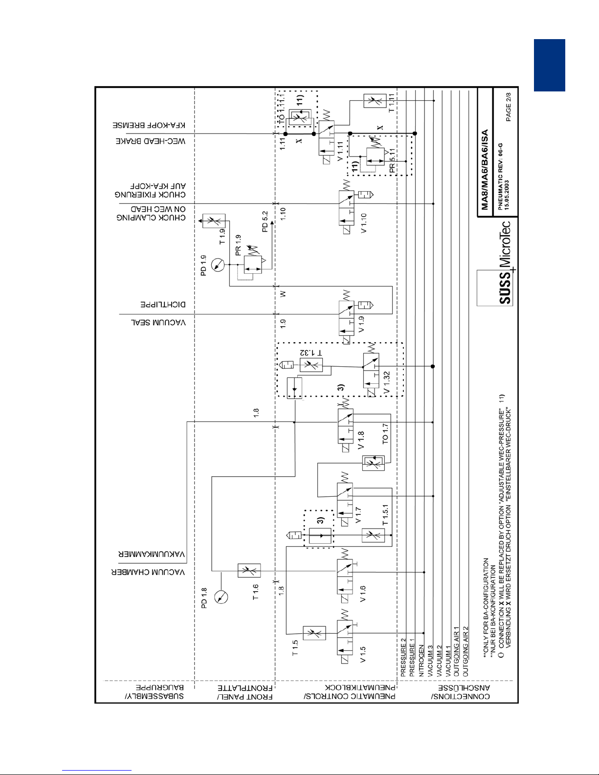
MA6 / MA8 - 3 Appendix - Rev.05 07-06
69
Appendix
3
Pneumatic Plan, Rev: 06-G, Sheet 2 of 8
Page 78

Page 79
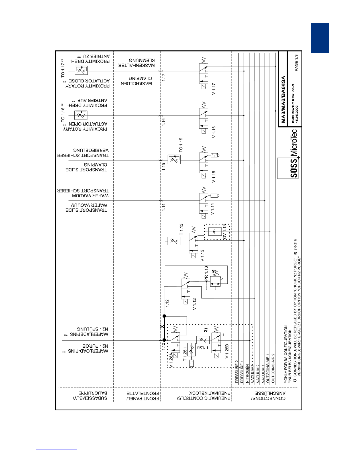
MA6 / MA8 - 3 Appendix - Rev.05 07-06
71
Appendix
3
Pneumatic Plan, Rev: 06-G, Sheet 3 of 8
Page 80

Page 81
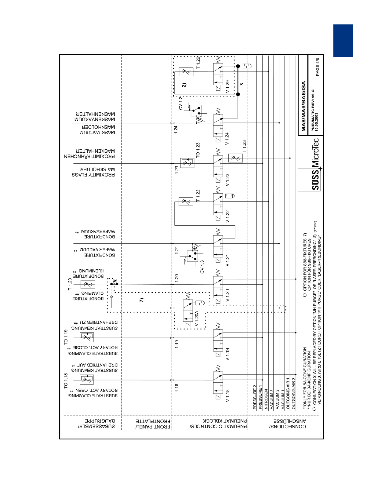
MA6 / MA8 - 3 Appendix - Rev.05 07-06
73
Appendix
3
Pneumatic Plan, Rev: 06-G, Sheet 4 of 8
Page 82

Page 83
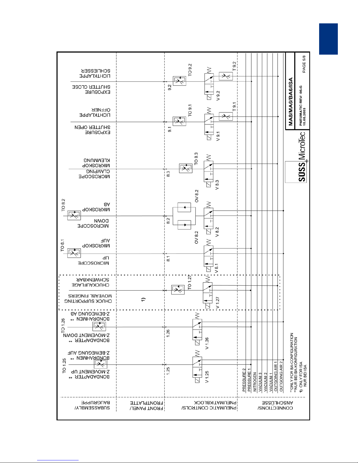
MA6 / MA8 - 3 Appendix - Rev.05 07-06
75
Appendix
3
Pneumatic Plan, Rev: 06-G, Sheet 5 of 8
Page 84

Page 85
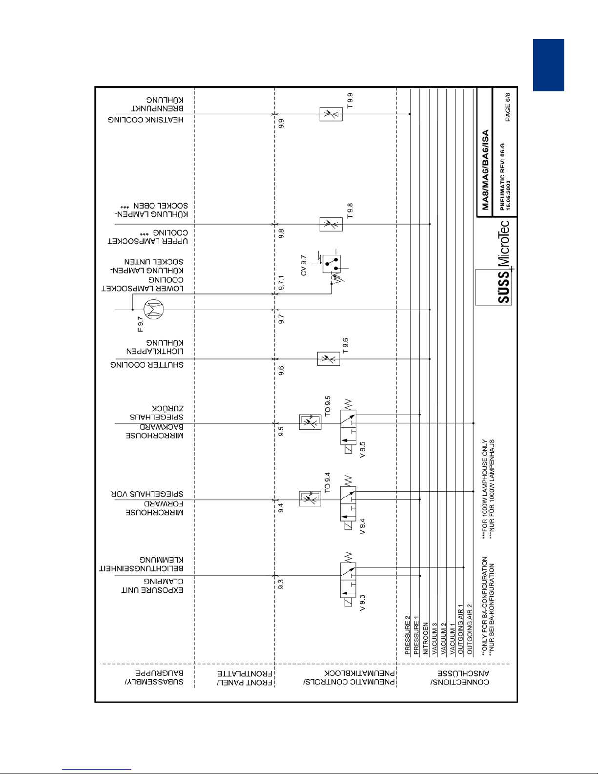
MA6 / MA8 - 3 Appendix - Rev.05 07-06
77
Appendix
3
Pneumatic Plan, Rev: 06-G, Sheet 6 of 8
Page 86

Page 87
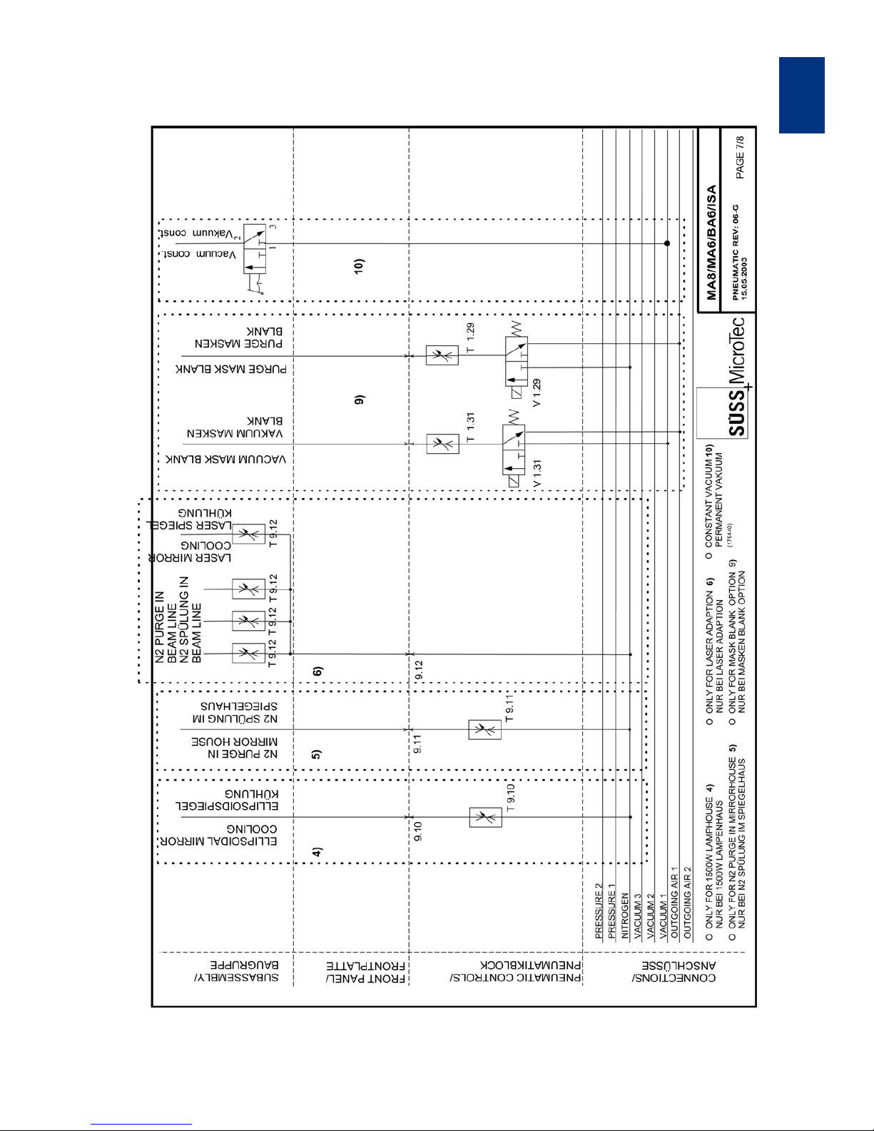
MA6 / MA8 - 3 Appendix - Rev.05 07-06
79
Appendix
3
Pneumatic Plan, Rev: 06-G, Sheet 7 of 8
Page 88

Page 89
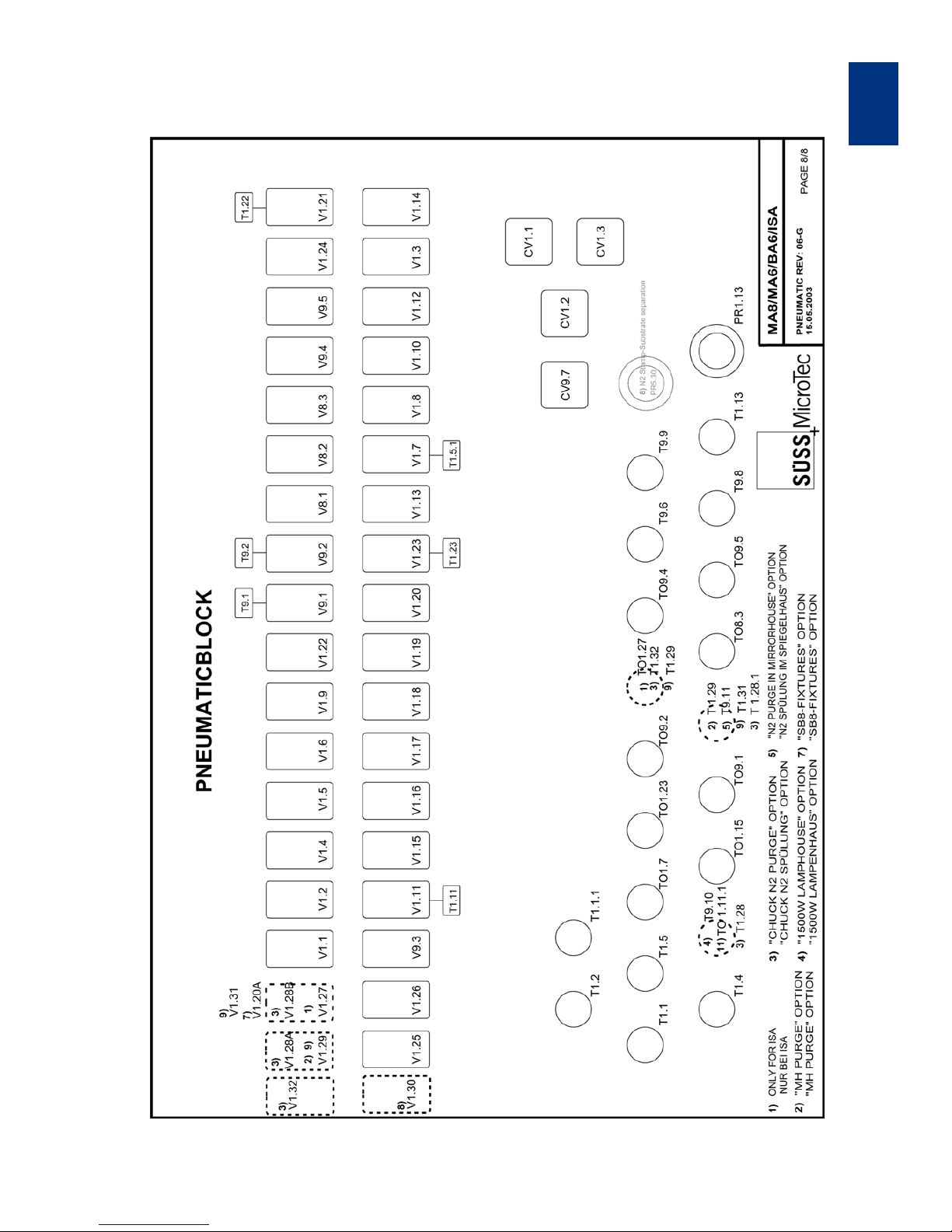
MA6 / MA8 - 3 Appendix - Rev.05 07-06
81
Appendix
3
Pneumatic Plan, Rev: 06-G, Sheet 8 of 8
Page 90

Appendix
MA6-8 / BA6-8 - 4 Appendix - Rev.05 07-06
82
3
3.6 Schematics of the Electronic System MA6/8 BA6/8
Item Description Assembly # Schematic Page
1 Mains connection 108278 103501 3 pages
2 N2-loss/interlock module 114170 103506
3 Microscope illumination 114162 103400
4 Cable microscope illumination, lamp house 113369 102451
5 Front panel 114156 103505
6 Keyboard 114145 103490
7b Junction board, standard 114142 182459
7c Junction board, with NFH, mot. stage, sep.
knife
173828 173829
8 Auxilliary PCB 168638 168697
9a Backplane, standard 114143 103488
9b Backplane, mot. stage/ separation knife 168687 168688 2 pages
10 Electronic rack 108277 103500
11 Extension cable junction board-cards 149754 182253
12 Microcontroller, 8 bit 174850 174851
13 Output card 113775 103207
14 Input card 113764 103225
15a Motor driver card, 2 channel 113824 103236
15b Motor driver card, 4 channel 166225 167593
16 Alignment stage 114197 103508
17 Pneumatic 108347 182458
18 TSA microscope manipulator 114171 103485
19 BSA stage 114173 103388
20 Exposure unit 114169 103394
21 Microscope M204/234+AL300, focus left 111835 103571
22 Microscope M204/234+AL300, focus right 111836 103571
23 Cable TSA focus left/right, AL300 114054 103373
24 Microscope BSA right 159309 162968
25 Microscope BSA left 159308 162969
26 Cable BSA focus left/right, AL300 114053 103468
27 Extension cable BSA focus left/right 160209 160707
28 Extension cable BSA magn. choice left/right 160210 160708
29 Cable focus controller - microscope 181729 181743
30 Cable adaption frame grapper 181719 182456
31 Cable data exchange - EISS 181725 181741
Page 91

Appendix
MA6-8 / BA6-8 - 4 Appendix - Rev.05 07-06
3
83
Page 92
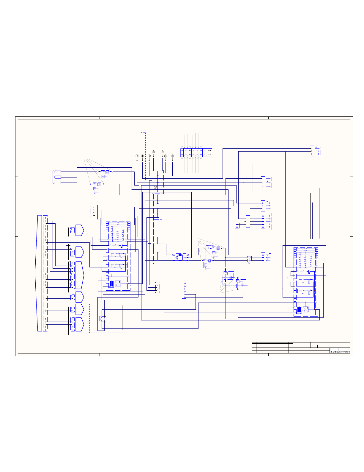
1 2 3 4
A
B
C
D
4
321
D
C
B
A
This drawing contains information which is the proprietary of Karl Suss Company.
It is received in confidence an its contends may not be disclosed without the prior
written consent of Karl Suss Company.
Sheet of
File :Drawn by:
Size : Date :
DrawingNo.: Rev.: AssemblyNo.:14
Machine: T itle:
Rev. Änd erung Datum Name
.DOC_FILE_NAME_NO_PATH
138-May-2006 A4
108278103501
Base Wiring GroundplateMA/BA6
LNPE
LNPE 123
1234
I n t I
12
I n t I I
12345
( 114142 ) - P30
N E T Z E I N G A N G
M A I N S I N
N E T Z A U S G A N G
M A I N S O U T D V C U
Elektronikeinschub
electronic rack
Lampenhaus 1000W
Rahmen Mikroskopbel.
Pneumatik
L
L
N
N
12345
678LN
-A1
123456
I n t I I I
12PE
Spannungsversorgung CIC
lamp power supply CIC
230V - 50 / 60 Hz or 208V / 2phase / 60Hz
-Z1
Not-Aus-Schaltgerät
emergency switch box
( 114154 )
Rückwand / back plane
Rückwand / back plane
back plane
Rückwand
Rückwand / back plane
Rückwand / back plane
Rückwand / back plane
Verteilerplatine / junction board
lamphouse 1000W
microscope illum. frame
pneumatic
( 150482 )
Flanschdose 6pol.
female conn. 6 pins
( 147979 )
Flanschst. 2pol.
male conn. 2 pins
( 146984 )
Flanschdose 4pol.
female conn. 4 pins
( 147621 )
( 149984 )
( 150582 )
Kaltgerätebuchse
mains supply jack
N2-Loss/Interlock
Schuko-Einbausteckdose
mains jack 2 pins + PE
Min.-Stiftstecker 5pol.
male min. conn. 5 pins
( 149294 )
AMP-Buchsenst. 3pol.
fem. AMP conn. 3 pins
( 1 x 147745
3 x 148897 )
8 x Klemme gn/ge / terminal block gn/ye ( 148393 )
11 x Klemme gr / terminal block gy ( 148392 )
rt
rd
gn/ge
gn/ye
sw
bk
sw
bk
ws
wh
br
bn
ws
wh
br
bn
gn
gn
ge
ye
gr
gy
ws
wh
br
bn
2 x LiY1.5 sw (149278)
1 x LiY1.5 gn/ge (146431)
sw
bk
sw
bk
gn/ge
gn/ye
integriert in Bgr. Pneumatik
part of pneumatic assy.
( -> 108347 )
14 24 34
13 23 33
F1
K3K1 K2
K1.1 K2.1
K3
K1.2
K3.1
K2
K2.2
K3.2
K1
A1(+) A2(-)
PE(-)
Y3 Y2S22S12S11 S11 S12 S21 Y1
G1
S33
44 54 64 72 8292 02
43 53 63 71 8191 01
S34
-F5
br
bn
bl
bu
gn/ge
gn/ye
Netzstecker
mains plug
sw
bk
sw
bk
gn/ge
gn/ye
sw
bk
sw
bk
gn/ge
gn/ye
sw
bk
sw
bk
sw
bk
sw
bk
sw
bk
sw
bk
sw
bk
gn/ge
gn/ye
sw
bk
sw
bk
sw
bk
sw
bk
sw
bk
sw
bk
gn/ge
gn/ye
gn/ge
gn/ye
rt
rd
rt
rd
ab Werk gebrückt ( sw )
bridge inserted by manufacturer ( bk )
sw
bk
br
bn
br
bn
bl
bu
bl
bu
bl
bu
bl
bu
br
bn
br
bn
Netzfilter
( 149983 )
mains filter
sw
bk
sw
bk
sw
bk
alle sonstigen Kabel, sofern nicht anders bezeichnet : AWG14
- sw / bk : 157491
alle Schutzleiter, sofern nicht anders bezeichnet : LiY 2,5
- gn/ge / gn/ye : 150873
-F2
-F1
Zweifachschutzschalter T4A
( 158611 )
dual protector
Zweifachschutzschalter
T5A ( 158612 ) oder / or T10A ( 156899 )
dual protector
4 x Kabelschuh 6,3 x 0,8 blau vollisoliert
4 x cable shoe with insulation coat
4 x Kabelschuh 6,3 x 0,8 blau vollisoliert
4 x cable shoe with insulation coat
-X10
-X9
-X8
-X5
-X6
27
28
29
30
3132
3334
35
36
37
38
Pilz PNOZ 10
-X1
2
3
456
8
9
101112
13
14
15
16
17
18
19
20
-X4
380mm360mm
340mm
-Q3
1 2 3 4 5 6 7 8 9 10111213 141516 171819 202122232425
X8 ( DVCU-Netzausgang )
Rückwand / backpanel
Z1 Filter
X10 Lamp Powersupply CIC
X 10A
X9 ( Elektronik-Rack )
Frontplatte links / left
F5 ( Not-Aus /EMO )
F4 ( Not-Aus / EMO )
Pneumatik
PE-Klemmleiste X2
Rahmen Mikroskopbel.
Haupterde Grundplatte / PE
Abdeckhaube / cover
12
ws
wh
br
bn
gn
gn
-X3
171819
20
PE- Terminalblock -X1
X2 : 2
X2 : 5
X2 : PE
Bl. 02 / B2
-Q2
Not-Aus-Schalter
emergency switch
( 149991 oder/or 149992 )
Bgr. Not-Aus-Schalter ( inkl. Anschlußkabel )
emergency switch assy. ( connection cable included )
( 114155 )
ws
wh
gn
gn
br
bn
ge
ye
Kabel / cable LiYY 4x0.5
Länge / length 1500mm
( 146089 )
( 158795 )
( 158795 )
Frontplatte / front panel ( 103505 Bl. 1 / D3...H3 )
12345678910
"splitfield" rechts / right
"splitfield" links / left
ws
wh
br
bn
gn
gn
ge
ye
gr
gy
rs
pk
bl
bu
rt
rd
sw
bk
vi
vt
Verteilerplatine ( 103487 Bl.1 ) Verteilerplatine
( 103487 Bl. 1 )
P29
P25
123
+5V
GND
Daten / data
ws
wh
br
bn
gn
gn
ge
ye
NC
NC
Verteilerplatine
( 103487 Bl. 1 )
P13
br
bn
bl
bu
12345
ws
wh
br
bn
gn
gn
ge
ye
gr
gy
12
rs
pk
bl
bu
PCB Mikroskopbel.
( 103400 Bl. 1 )
PCB Mikroskopbel.
( 103400 Bl. 1 )
NC
12
Verteilerplatine
( 103487 Bl. 1 )
P38
NC
bl
bu
-W3001 -W3002 -W5001 -W3003
-W1001
-J38
-J25
-J13
P10P9
-J9
-J10
-W3005
-W3004
-J29
gn/ge
gn/ye
gn/ge
gn/ye
gn/ge
gn/ye
Abdeckhaube
Frontplatte links
cover
front panel ( left side )
-W3006
-W3007
+24VGND
sw
bk
sw
bk
Not-Aus-Schaltgerät
emergency switch box
( 150482 )
14 24 34
13 23 33
F1
K3K1 K2
K1.1 K2.1
K3
K1.2
K3.1
K2
K2.2
K3.2
K1
A1(+) A2(-)
PE(-)
Y3 Y2S22S12S11 S11 S12 S21 Y1
G1
S33
44 54 64 72 82 92 02
43 53 63 71 81 91 01
S34
-F4
ab Werk gebrückt
bridge inserted by manufacturer
sw
bk
Pilz PNOZ 10
-F3
Zweifachschutzschalter T1,6A
( 166360 )
dual protector
4 x Kabelschuh 6,3 x 0,8 blau vollisoliert
4 x cable shoe with insulation coat
39
40
41
42
( 158795 )
24
13
LNPE
sw
bk
sw
bk
gn/ge
gn/ye
-X10A
17
( 150582 )
Schuko-Einbausteckdose
mains jack 2 pins + PE
all grounding wires - if not individually marked
all other wires - if not individually marked
Energized also when
EMO is activated
*
*
*
*
*
*
**
*
*
*
*
!!!
LiYY 2x0,5
LiYY 4x0,5
Hauptschalter
main switch
Moeller T3-1-102
Propak PHB2
Propak PHB2
Propak PHB2
Frontplate rightLamphouse
Grundplatte
ground plate
gn/ge
gn/ye
Frontplatte rechts
frontplate right
gn/ge
gn/ye
Illum
Mains
P-Supply
LiYY 2x0,5
PCB junction board
PCB junction boardPCB junction boardPCB mic.ill u mi n.PCB mic.illumination
on / off switch
09
10
11
12
-ESB -R1 und +Heissleiter
-R2 und +Heissleiter
-Rev10 und +X10A +F6
+P9 +P10 F38
02.07.99
21.07.00
05.06.01
26.09.01
lg
lg
lg
jl
13 F6 entf ./Ansch.A1,X10A neu, Bezeichnungen 10.08.05 M.Hoppe
M.HoppeAnschluß -A1 neu14 08.05.06
Page 93
1 2 3 4
A
B
C
D
4321
D
C
B
A
-T1
vio
or
gr
gn gnrtblbrge
110V
110V
12V
8V
8V
vioye bn bu rd gngn
gy
or
( 149985 )
Netztrafo Mikroskopbel.
mains transformer microscope ill.
1 x Klemme gn/ge / term. block gn/ye ( 149393 )
9 x Klemme gr / term. block gy ( 149392 )
Aderendhülse
end splice
Aderendhülsen / end splices :
- or / or : 0.5 ( 149275 )
- ws / wh : 0.75 ( 149277 )
- ge / ye : 1.0 ( 149277 )
-W3008
1 2 3 41 2
wswhbrbngngnge
ye
grgyrs
pk
-X2
12345
6
78910111213
14
151617
18
-F3 : 40
-F3 : 42
-X1 : PE
Bl. 01 / -F3
PCB Mikroskopbel.
( 103400 Bl. 1 )
PCB Mikroskopbel.
( 103400 Bl. 1 )
P2P1
1 x Sicherungsklemme / fuse terminal ( 161675 )SL12 /
80 002
169114
-R1
+ESB und F-Automat
+ESB07
08
8.04.99
8.04.99
lge
lge
-ESB / + Heißleiter -R109 2.07.99 lge
sw
bk
sw
bk
sw
bk
gn/ge
gn/ye
gn/ge
gn/ye
+ Heißleiter -R210 21.07.00 lge
- Rev 10 / + X10A u. F611 5.06.01 lge
J1 J2
12 J1, J2 26.9.01 jla
Page 94
1 2 3 4
A
B
C
D
4321
D
C
B
A
.DOC_FILE_NAME_NO_PATH
Sheet of
File :
3 3
Drawn by:
Size : Date : 12-Aug-2005
J.Wanning
A4_l
DrawingNo.: Rev.: AssemblyNo.:
108278
12
103501
Machine: Title:
Base Wiring GroundplateMA/BA6
Rev. Änderung Datum Name
Error : \\Augustus\Programme\Design Explorer 99 SE\System\microtec_logo_1.BMP File Not Supported
Rev.: 13
assy. mains connection
This drawing contains information which is the proprietary of Karl Suss Company.
It is received in confidence an its contends may not be disclosed without the prior
written consent of Karl Suss Company.
Kabelliste für Bgr. Grundverdrahtung zum Stromlaufplan
-W3001
-W3002
-W3003
-W3004
-W3005
-W3006
-W3007
-W3008
-W5001
-W1001
-W1002
Netzleitung 3 x 1,5
Netzleitung 3 x 0,75
LiYY 7 x 0,25
Ruflakabel 10pol.
Sondenkabel 2 x 0.14
LiYY 4 x 0.5
LiYY 2 x 0.5
LiYY 5 x 0.25
LiYY 2 x 0.5
LiYY 4 x 0.25
LiYY 6 x 1.0
146474
149784
148614
146405
146407
146405
146406
150824
146089
147357
keine
Kabel Nr. Kabeltyp EDV-Nr.
+ESB und F-Automat
+ESB
07
08
8.04.99
8.04.99
lge
lge
-ESB / + Heißleiter -R1
09
2.07.99 lge
+ Heißleiter -R2
10
21.07.00 lge
- Rev 10 / + X10A u. F6
11
5.06.01 lge
12
diverse in Plan 01 + 02 26.09.01 jla
Page 95
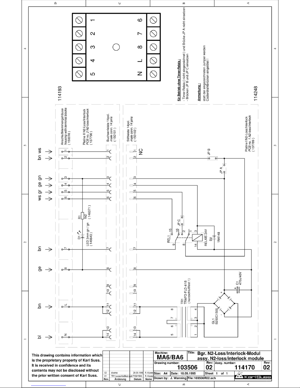
Page 96
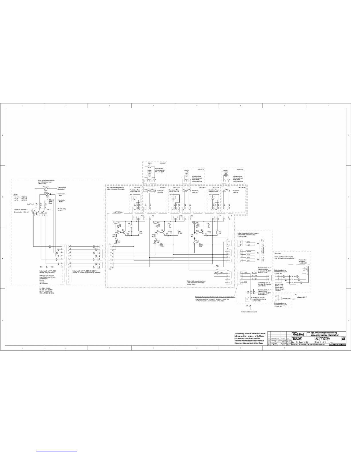
Page 97
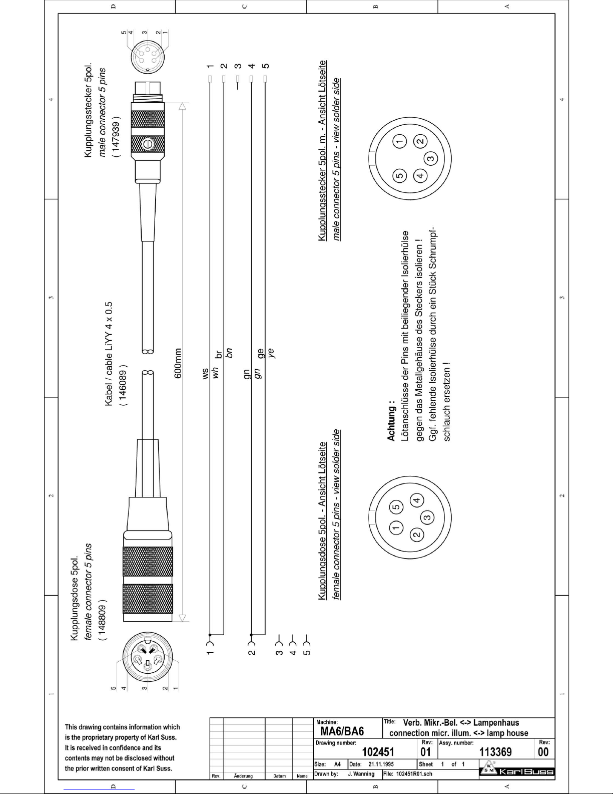
Page 98
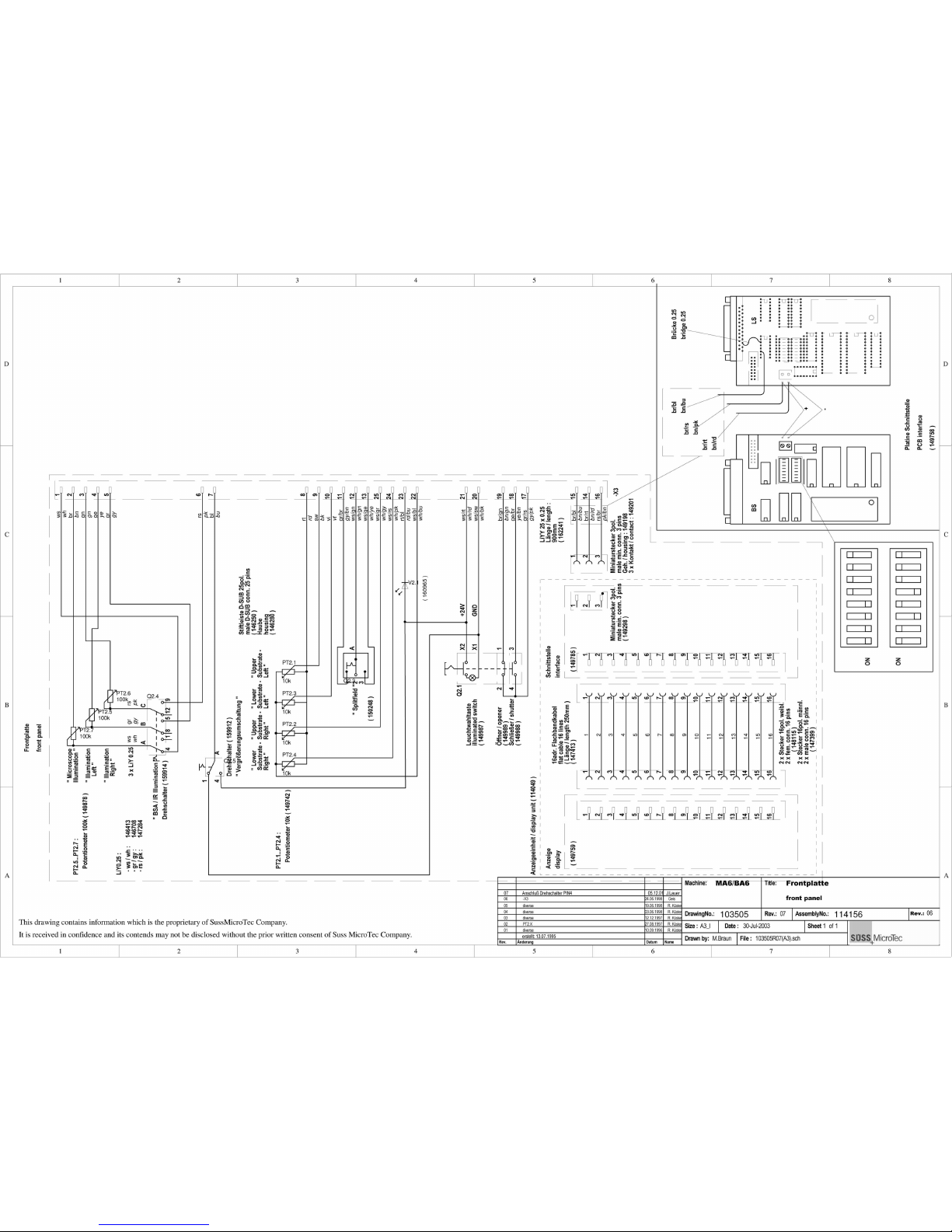
Page 99
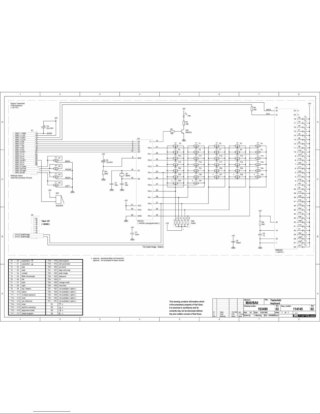
Page 100
1 2 3 4 5 6 78
A
B
C
D
8
7654321
D
C
B
A
182459R01.Sch
Sheet of
File :
11
Drawn by:
Size : Date :
27-Nov-2001
J.Lauer
A2_l
DrawingNo.: Rev.: AssemblyNo.:
114142
01
182459
Machine: Titl e: Verteilerpl. mit N2-Purge in MH,CH,LAMA6/BA6
Rev. Änderung Datum Name
Rev.: 00
junction board N2-purge MH,CH,LA
This drawing contains information which is the proprietary of Karl Suss Company.
It is received in confidence an its contends may not be discl osed without the prior
written consent of Karl Suss Company.
+24V
+5V
+24V
+5V
+12V VCU
+5V BA6
GND
GND
-12V VCU
R2
4k7
R1
4k7
TR1
2N2222A
D1
1N4148
REL1
HB2
R4
4k7
R3
4k7
D2
1N4148
REL2
HB2
R9
2k
M1
TESTP
R10
2k
TR2
2N2222A
M3
TESTP
R6
270
R5
270
IC1
CNY17-1
M2
TESTP
R7
1k
R8
1k
IC2
CNY17-1
1
2
3
4
5
6
7
8
9
10
1
2
3
4
5
6
7
8
9
10
P22
P25
GND VCU
1
2
3
4
5
6
7
8
9
10
11
12
13
14
15
16
S8.3
S8.4
S8.5
S8.6
S8.1
S8.2
+24V
+24V
+24V
+24V
+24V
+24V
+24V
+24V
+24V
+24V
+24V
GND
GND
GND
GND
GND
GND
GND
GND
GND
GND
GND
GND
GND
+5V
+5V
+5V
+5V
+5V
+5V
+5V
+5V
F2
T3.15A
F1
T2A
1
2
3
4
5
6
7
8
9
10
11
12
13
14
15
16
17
18
19
20
21
22
23
24
25
26
1
2
3
4
5
6
7
8
9
10
11
12
13
14
15
16
17
18
19
20
21
22
23
24
25
26
1
2
3
4
5
6
7
8
9
10
11
12
13
14
15
16
17
18
19
20
21
22
23
24
25
26
1
2
3
4
5
6
7
8
9
10
11
12
13
14
15
16
17
18
19
20
21
22
23
24
25
26
1
2
3
4
5
6
7
8
9
10
11
12
13
14
15
16
17
18
19
20
21
22
23
24
25
26
1
2
3
4
5
6
7
8
9
10
11
12
13
14
15
16
17
18
19
20
21
22
23
24
25
26
1
2
3
4
5
6
7
8
9
10
11
12
13
14
15
16
17
18
19
20
21
22
23
24
25
26
1
2
3
4
5
6
7
8
9
10
11
12
13
14
15
16
17
18
19
20
21
22
23
24
25
26
1
2
3
4
5
6
7
8
9
10
11
12
13
14
15
16
17
18
19
20
21
22
23
24
25
26
1
2
3
4
5
6
7
8
9
10
11
12
13
14
15
16
17
18
19
20
21
22
23
24
25
26
1
2
3
4
5
6
7
8
9
10
11
12
13
14
15
16
17
18
19
20
1
2
3
4
5
6
7
8
9
10
11
12
13
14
15
16
17
18
19
20
1
2
3
4
5
6
7
8
9
10
11
12
13
14
15
16
17
18
19
20
21
22
23
24
25
26
1
2
3
4
5
6
7
8
9
10
11
12
13
14
15
16
17
18
19
20
1
2
3
4
5
6
7
8
9
10
11
12
13
14
15
16
17
18
19
20
1
2
3
4
5
6
7
8
9
10
11
12
13
14
15
16
17
18
19
20
1
2
3
4
5
6
7
8
9
10
11
12
13
14
15
16
1
2
3
4
5
6
7
8
9
10
11
12
13
14
15
16
1
2
3
4
5
6
1
2
3
1
2
3
4
5
6
7
8
9
10
1
2
3
4
5
1
2
3
4
1
2
3
4
1
2
P12
P13
P14
P15 P16
P17
P18
P19
P20
P23
P24
P26
P27
P28
P29
P30
C1
C2
C3
C4 C5
C6
C7
C8
C9
P21
Verteilerplatine
junction board
Exposure unit Sensor table I BSA signals BSA motors
Sensor table II Pneumatik I TSA microscope Mains switch lampDisplay
TSA microscope sensorsPneumatik II
+24V / +5V
Check value Interlock
Key panel
V1.25
V1.26
( 36001597 )
CV1.3
Output
Backplane
Video
Input
Front panel Focus
DCM control TSAOutputAdjustment stage DCM control
CPU
BSA right DCM control BSA left DCM controlInput
S8.3
S8.4
S8.5
S8.6
S8.1
S8.2
an C2
to C2
von P18
from P18
12345
6
135
246
+5V VCU
blank
+5V
grab
GND
left
splitfield
right
video select (BSA/TSA)
left focus motor
right focus motor
+12V
-12V
P31
P32
123
8914
1516
123
8914
1516
S1.15
S1.14
S1.13
S1.12
S1.11
S 1.16
Tisch-Sensor Res. 2
Tisch-Sensor Res. 3
Tisch-Sensor Res. 4
+24V
GND
switched GND
M4
TESTP
M6
TESTP
M5
TESTP
1
2
3
4
5
6
7
8
9
10
11
12
13
14
15
16
17
18
19
20
21
22
23
24
25
26
C10
DCM Driver 4 channel
1
2
3
4
5
6
7
8
9
10
11
12
13
14
15
16
P35
Stage - motors
1
2
3
4
5
6
7
8
9
10
11
12
13
14
15
16
17
18
19
20
P34
PC bus control
1
2
3
4
5
6
7
8
9
10
11
12
13
14
15
16
17
18
19
20
P33
mot. chuck transport
+5V
+24V
+24V
1
2
P37
magnification right
+24V
1
2
P36
magnification left
1N4004
1N4004
Brücke für BA6 ABS
jumper for BA6 ABS
1K
R11
1
2
P38
JP 1
JP 2
123
4
123
4
JP 3
V1.29
V1.30
Ursprung 103487R06
V1.28a+b
V1.28a+b only N2 purge in chuck
V1.29 only N2 purge in mask
V1.30 only N2 purge in lance
Options:
01 V1.29 auf PIN 8 12.11.01 J.Lauer
 Loading...