

Page 1

SMR Linux Series
Smart Megapixel Video Recorder
User Manual
Release 1.0
Page 2

2
About This Document
This manual introduces the hardware components of THE SYSTEM series and
describes how to install them. It also provides an overview of Server surveillance
functionality, and includes the functions of Video Management Software for
operating and monitoring a Server network.
Version History
Description
Date
1.0
Initial release
May 2015
Page 3

3
All Rights Reserved © Surveon Technology 2015
Copyright Statement
No part of this publication may be reproduced, transmitted, transcribed,
stored in a retrieval system, or translated into any language or computer
language, in any form or by any means, electronic, mechanical, magnetic,
optical, chemical, manual or otherwise, without the prior written consent of
Surveon Technology Inc.
Disclaimer
Surveon Technology makes no representations or warranties with respect to
the contents hereof and specifically disclaim any implied warranties of
merchantability or fitness for any particular purpose. Furthermore, Surveon
Technology reserves the right to revise this publication and to make changes
from time to time in the content hereof without obligation to notify any
person of such revisions or changes. Product specifications are also subject to
change without notice.
Trademarks
Surveon and Surveon logo are trademarks of Surveon Technology Inc. Other
names prefixed with “NVR” and “SMR” are trademarks of Surveon Technology
Inc.
Microsoft Windows and Windows are registered trademarks of Microsoft
Corporation.
Linux is a trademark of Linux Torvalds.
Solaris and Java are trademarks of Sun Microsystems, Inc.
All other names, brands, products or services are trademarks or registered
trademarks of their respective owners.
Page 4

4
Table of Contents
About This Document .................................................................... 2
Version History ........................................................................... 2
Copyright Statement ......................................................................... 3
Table of Contents ............................................................................. 4
Safety Precautions .......................................................................... 14
Device Site Recommendations ............................................................ 14
Chapter 1. Product Overview ............................................................. 15
1.1. Features and Benefits ............................................................. 15
1.2. Specifications for the Linux SMR Series ........................................ 16
1.2.1. Hardware Specifications ...................................................... 16
1.2.2. VMS Specifications ............................................................. 17
Chapter 2. Hardware Overview .......................................................... 19
2.1 Front Panel ........................................................................... 19
2.2. Rear Panel ........................................................................... 20
2.3. Hard Drive Designation ............................................................ 21
2.4. LED Definitions ..................................................................... 22
2.4.1. Desktop System Front Panel LEDs ............................................ 22
2.4.2. Rear Panel Ethernet LED ...................................................... 23
Chapter 3. Software Overview ........................................................... 24
3.1. Software Introduction ............................................................. 24
3.2. Module Framework ................................................................ 25
3.3. System Architecture ............................................................... 27
3.3.1. Standalone Server (Client-Server All-in-One) .............................. 28
3.3.2. Standalone Server + Remote Client (Web Client / SPhone Client) ...... 29
3.3.3. Multiple Servers + SCC Client ................................................. 31
3.3.4. Network Requirements ........................................................ 34
Opening Ports ...................................................................... 34
Warnings / Precautions ........................................................... 34
3.4. Port Forwarding .................................................................... 35
Page 5

5
3.4.1. Port Forwarding for Accessing VMS Server ................................. 36
Chapter 4. Installation ..................................................................... 39
4.1. Before You Start .................................................................... 39
4.1.1. Checklist for Operating Environment........................................ 39
4.1.2. Checklist for Network Topology .............................................. 39
4.2. Hard Drive Installation ............................................................ 40
4.2.1. Hard Drive Installation Prerequisites ........................................ 40
4.2.2. Inserting Hard Drive into Drive Tray (Desktop Series) .................... 40
4.3. System Connections ............................................................... 42
4.4. Powering up SMR ................................................................... 44
4.4.1. SMR Systems .................................................................... 44
4.5. Logging into SMR Series ........................................................... 45
4.6. Run the Install Wizard ............................................................. 46
Chapter 5. Basic System Settings ........................................................ 59
5.1. Storage Management .............................................................. 59
5.2. Adding Cameras to the Server ................................................... 61
5.2.1. Automatic Scan for Cameras ................................................. 61
5.2.2. Manually Adding Cameras ..................................................... 63
5.3. Setting Recording Schedule ...................................................... 65
5.3.1. Recording Schedule ............................................................ 65
5.4. Setting up Live View ............................................................... 67
Chapter 6 Live View ........................................................................ 68
6.1. Live View Window Overview ..................................................... 68
6.2. View Setup .......................................................................... 71
6.2.1. Switching Between Different Screen Divisions ............................. 71
Creating and Using New Screen Divisions ...................................... 71
Auto-flipping Pages ............................................................... 71
Screen Division Page Use ......................................................... 71
Fisheye View ....................................................................... 72
E-map ............................................................................... 73
Secondary Display ................................................................. 75
Page 6

6
6.3. Functionality Within Views ....................................................... 76
6.3.1. Digital Zoom .................................................................... 76
6.3.2. Instant Playback ................................................................ 77
6.3.3. Manual Recording .............................................................. 79
6.3.4. Others ............................................................................ 80
Image Settings ..................................................................... 80
Insert ................................................................................ 81
Send to Large Channel ............................................................ 82
Reconnect .......................................................................... 82
Remove the Camera .............................................................. 82
6.4. Full Screen View ................................................................... 83
6.4.1. Entering Full Screen View ..................................................... 83
6.4.2. Exiting Full Screen Mode ...................................................... 83
Chapter 7. Server Setup ................................................................... 84
7.1. Server Settings ...................................................................... 84
7.1.1. General Server Settings ....................................................... 84
7.1.2. To perform Notification Setting .............................................. 87
7.1.3. Scheduling Recording .......................................................... 90
7.1.4. Storage Management .......................................................... 92
7.1.5. Pre/Post Recording ............................................................ 94
Chapter 8. Camera Setup .................................................................. 95
8.1. Adding Cameras .................................................................... 95
8.1.1. Automatic Scan for Cameras ................................................. 95
8.1.2. Manually Adding Cameras ..................................................... 98
8.2. Camera General Settings........................................................ 100
8.2.1. General Camera Settings ..................................................... 100
8.2.2. Edit Camera .................................................................... 103
8.2.3. OSD Settings ................................................................... 105
8.2.4. Privacy Mask Settings ......................................................... 107
8.3. Camera Image and Quality Settings ........................................... 109
8.3.1. Camera Image Settings ....................................................... 109
Page 7

7
8.3.2. Advanced Video Settings ..................................................... 112
8.4. VI Settings ......................................................................... 115
8.4.1. Camera Motion Detection .................................................... 116
Configuring and Editing Detection Windows .................................. 117
Deleting a Detection Window .................................................. 117
8.4.2. General Motion Detection .................................................... 118
Enabling or Disabling a Detection .............................................. 118
Configuring and Editing Detection Windows .................................. 118
Testing Detection Windows ..................................................... 119
Deleting a Detection Window .................................................. 119
8.4.3. Tampering Detection ......................................................... 120
Enabling or Disabling a Detection .............................................. 120
Configuring Tampering Detection .............................................. 120
Testing Tampering Detection ................................................... 121
8.4.4. Forbidden Area Detection .................................................... 122
Enabling or Disabling a Detection .............................................. 122
Configuring and Editing Detection Windows .................................. 122
Testing Detection Windows ..................................................... 123
Deleting a Detection Window .................................................. 123
8.4.5 Intrusion Detection ............................................................ 124
Enabling or Disabling a Detection .............................................. 124
Configuring and Editing Detection Windows .................................. 124
Testing Detection Windows ..................................................... 125
Deleting a Detection Window .................................................. 125
8.4.6. Virtual Fence .................................................................. 125
Enabling or Disabling a Detection .............................................. 126
Configuring and Editing Detection Windows .................................. 126
Testing Detection Windows ..................................................... 127
Deleting a Detection Window .................................................. 128
8.4.7. Missing Object Detection..................................................... 129
Enabling or Disabling a Detection .............................................. 129
Page 8

8
Configuring and Editing Detection Windows .................................. 129
Testing Detection Windows ..................................................... 130
Deleting a Detection Window .................................................. 130
8.4.8. Foreign Object Detection .................................................... 131
Enabling or Disabling a Detection .............................................. 131
Configuring and Editing Detection Windows .................................. 131
Testing Detection Windows ..................................................... 132
Deleting a Detection Window .................................................. 132
8.4.9. Tailgating Detection .......................................................... 133
Configuring and Editing Detection Windows .................................. 133
Testing Detection Windows ..................................................... 134
Deleting a Dividing Line ......................................................... 134
Enabling or Disabling a Detection .............................................. 134
8.4.10. Go In/Out Detection ........................................................ 135
Configuring and Editing Detection Windows .................................. 135
Testing Detection Windows ..................................................... 136
Deleting a Detection Window .................................................. 136
Enabling or Disabling a Detection .............................................. 136
8.5. PTZ Settings ....................................................................... 137
8.5.1. PTZ Settings .................................................................... 137
8.5.2. PTZ Preset Settings ........................................................... 140
Adding a Preset ................................................................... 142
Deleting a Preset ................................................................. 142
8.5.3. PTZ Patrol Settings............................................................ 143
8.5. PTZ Controls ....................................................................... 146
8.5.1. Directional Pad ................................................................ 146
Pan and Tilt ....................................................................... 146
8.5.2. Functional Buttons ............................................................ 147
Home ............................................................................... 147
Preset .............................................................................. 147
Auto Pan ........................................................................... 147
Page 9

9
Patrol .............................................................................. 147
Zoom ............................................................................... 147
Focus ............................................................................... 147
8.5.3. Deleting a Camera ............................................................ 148
Chapter 9. Alarms and Events .......................................................... 151
9.1. Alarm Rules ........................................................................ 151
9.1.1. Adding an Alarm Rule ......................................................... 152
Conditions ......................................................................... 153
Actions ............................................................................. 155
Alarm Scheduling ................................................................. 160
9.2. Event Log .......................................................................... 162
9.2.1. Exporting a Log ................................................................ 163
9.2.2. Searching the Event Log...................................................... 163
System ............................................................................. 164
Event Type ........................................................................ 164
Operation .......................................................................... 164
Module Name ..................................................................... 164
Device Name ...................................................................... 165
User Name ......................................................................... 165
Performing a Search ............................................................. 165
9.2.3. System Alarm View............................................................ 166
Chapter 10 Search and Playback ....................................................... 167
10.1. Introduction ..................................................................... 167
10.2. Time Search ..................................................................... 168
10.2.1. Time Selection ............................................................... 168
Specified Time .................................................................... 168
10.2.2. Use of Various Views Selection ............................................ 169
10.2.3. Camera Selection ............................................................ 169
10.2.4. Timeline ....................................................................... 170
10.2.5. Playback ...................................................................... 170
Capturing Screenshot ............................................................ 172
Page 10

10
Capturing Video Clip ............................................................. 172
10.3. VI Search ......................................................................... 174
10.3.1. Creating a VI Search ......................................................... 174
Time Selection .................................................................... 174
Camera Selection................................................................. 175
Setting New Search Criteria .................................................... 176
10.3.2. Using the Search Results .................................................... 177
Selecting the Result.............................................................. 177
Result Playback ................................................................... 177
10.4. Event Search..................................................................... 180
10.4.1. Creating an Event Search ................................................... 180
Time Selection .................................................................... 180
Camera Selection................................................................. 181
Setting Event Search Criteria ................................................... 182
10.4.2. Using the Search Results .................................................... 183
Selecting the Result.............................................................. 183
Result Playback ................................................................... 184
Chapter 11. VMS Setup ................................................................... 186
11.1. Camera ........................................................................... 186
11.1.1. Edit Camera .................................................................. 186
11.1.2. Advanced Camera............................................................ 186
11.1.3. General Camera Settings ................................................... 187
11.1.4. Image Settings................................................................ 187
11.1.5. PTZ Camera Settings ........................................................ 187
11.1.6. PTZ Preset Settings .......................................................... 187
11.1.7. PTZ Patrol Settings .......................................................... 187
11.1.8. OSD Settings .................................................................. 187
11.1.9. Mask Settings ................................................................. 187
11.1.10. Optimize Settings .......................................................... 188
11.2. VI ................................................................................... 189
11.2.1. Camera Motion Detection .................................................. 189
Page 11

11
11.2.2. General Motion Detection .................................................. 189
11.2.3. Tampering Detection ........................................................ 190
11.2.4. Forbidden Area Detection .................................................. 190
11.2.5. Intrusion Detection .......................................................... 190
11.2.6. Virtual Fence Detection .................................................... 190
11.2.7. Missing Object Detection ................................................... 190
11.2.8. Foreign Object Detection ................................................... 190
11.2.9. Tailgating Detection ......................................................... 191
11.2.10. Go In/Out Detection ....................................................... 191
11.3. Recording ........................................................................ 192
11.3.1. Schedule ...................................................................... 192
11.3.2. Storage ........................................................................ 192
11.3.3. Pre/Post Recording .......................................................... 192
11.4. Alarm .............................................................................. 193
11.4.1. Alarm Rules ................................................................... 193
11.4.2. Email .......................................................................... 193
11.4.3. SMS ............................................................................. 193
11.4.4. Digital I/O Settings .......................................................... 194
11.5. Account ........................................................................... 195
11.5.1. Accounts ...................................................................... 196
Add Account To add an account to the domain: ............................. 196
Editing an Account ............................................................... 198
Changing an Account Password ................................................. 199
Deleting an Account ............................................................. 199
11.5.2. Account Authority Settings ................................................. 200
11.6. Network .......................................................................... 201
11.6.1. NVR Settings .................................................................. 201
11.6.2. Web Server ................................................................... 202
11.6.3. Multiple LAN .................................................................. 203
11.6.4. DHCP Settings ................................................................ 204
11.6.5. DDNS Setting ................................................................. 205
Page 12

12
11.6.6. Port Mapping ................................................................. 205
11.7. System ............................................................................ 207
11.7.1. General ........................................................................ 207
11.7.2. Advanced...................................................................... 207
11.7.3. Display Resolution Settings ................................................. 208
11.7.4. Language ...................................................................... 208
11.7.5. Map Editor .................................................................... 209
11.7.6. Log Viewer .................................................................... 209
11.7.7. Optimize Settings ............................................................ 209
11.8. Maintenance ..................................................................... 210
11.8.1. Stream Status ................................................................ 210
11.8.2. Upgrade ....................................................................... 211
11.8.3. Import/Export ................................................................ 211
Importing Parameters ........................................................... 212
Exporting Parameters ............................................................ 212
11.8.4. License ........................................................................ 213
11.8.5. System Backup ............................................................... 214
11.8.6. Clear SCC Data ............................................................... 214
11.8.7. Remote Assistant ............................................................ 215
Chapter 12. Remote Web Client and SPhone Client for Simple Use (Optional)216
12.1. Software Installation for Remote Control .................................. 217
12.1. Installing the VMS .............................................................. 217
12.2. Starting the VMS Client ........................................................ 221
12.3. Starting the Web Client........................................................ 223
12.3.1. Checking the Software Version ............................................ 223
12.3.2. Use of 1x/4x views .......................................................... 223
12.3.3. PTZ Control ................................................................... 224
12.3.4. Playback Settings ............................................................ 225
12.4. Installing and Starting the SPhone Client on iOS Devices ............... 226
12.4.1. Installing the SPhone Client (Optional) ................................... 226
12.4.2. Starting the SPhone Client ................................................. 226
Page 13

13
12.4.3. Checking the Software Version ............................................ 227
12.4.4. Live View/Playback on the SPhone Client ............................... 227
12.5. Installing and Starting the SPhone Client on Android Devices ......... 232
12.5.1. Installing the SPhone Client (Optional) ................................... 232
12.5.2. Starting the SPhone Client ................................................. 232
12.5.3. Checking the Software Version ............................................ 233
12.5.4. Live View on the SPhone Client ............................................ 234
Page 14
14
Safety Precautions
Electric Shock Warning
This equipment may cause electric shocks if not handled properly.
Access to this equipment should only be granted to trained operators
and maintenance personnel who have been instructed of, and fully
understand the possible hazardous conditions and the consequences of
accessing non-field-serviceable units such as the power supplies.
The system must be unplugged before moving, or in the even that it
becomes damaged.
Reliable Grounding
Particular attention should be given to prepare reliable grounding for the
power supply connection. It is suggested to use a direct connection to the
branch circuit. Check for proper grounding before powering on the device.
Overloading Protection
The device should be installed according to specifications. Provide a suitable
power source with electrical overload protection. Do not overload the AC
supply branch circuit that provides power to the device.
ESD Precautions
Please observe all conventional anti-ESD methods while handling the device.
The use of a grounded wrist strap and an anti-static work pad are
recommended. Avoid dust and debris in your work area.
Device Site Recommendations
The device should be installed according to specifications. This device should
be operated at a site that is:
Clean, dry, and free of excessive airborne particles.
Well-ventilated and away from heat sources such as direct sunlight
and radiators.
Clear of vibration or physical shock.
Away from strong electromagnetic fields produced by other devices.
Available with properly grounded wall outlet for power. In regions
where power sources are unstable, apply surge suppression.
Available with sufficient space behind the device for cabling.
Page 15

15
Chapter 1. Product Overview
1.1. Features and Benefits
The SMR series is a state-of-the-art network video recorder features RAID, low
power. With bay hard disk trays, the system series is the best in class SMR that
supports megapixel quality video of 4 to 64 channels for video retention periods
from 7 to 40 days or more. In addition, the system series is fully burn-in-tested and
uses preloaded Enterprise VMS to eliminate compatibility issues while reducing
maintenance overheads. It is out of question that the system series is the most
reliable and cost-effective solution for small to medium sized surveillance needs.
Page 16

16
1.2. Specifications for the Linux SMR Series
1.2.1. Hardware Specifications
SMR2100
SMR8300E Series
SMR8300A Series
System Processor
Intel® Dual Core
Intel® Dual Core i3
Intel Core i7
System Memory
DDR3 2GB
DDR3 4GB (up to 16GB)
Operating System
Linux Embedded System
Storage
3.5" SATA HDDs x2
3.5" SATA HDDs x8
HDD hot swappable with LED status indicator
I/O Interface
RJ-45:
2x Gigabit Ethernet
USB: 4x USB2.0
VGA(D-Sub): x1,
E-STAT: x1
RJ-45: 2x Gigabit Ethernet
USB: 6x USB2.0
VGA(DVI): x1
HDMI: x1
COM: x1
RAID
Non RAID, RAID 1
Non RAID, RAID 1, 5, 6
Electrical
Input Voltage:
12VDC, 5A
Power Supply: 43W
Input Voltage: 100-240 V, 3.5A
Power Supply: 430W
Operating Environment
Temperature: 5° C to 40° C
Humidity: 5% to 80% (non-condensing)
LED Indicator
Yes (Fan, Temperature, Power, HDD)
Dimensions (mm)
190(H) x 110(W) x
245(D) mm
310(H) x 175(W) x 380(D) mm
Weight
(without hard drives)
3kg (without HDD)
8.9kg (without HDD)
Certificate
BSMI, CB, FCC / CE Class B, UL60959/ IEC 60950
Warranty
3 years
Page 17

17
1.2.2. VMS Specifications
Live View
• Real-time network camera discovery
• Versatile views of various screen divisions
• Multiple views supported
• View patrolling for single or multiple views
• Real time video/event alarm display
• Support 3 installation modes and 5 different
fisheye Dewarp display modes
• Support live audio
eMAP
• Drag-n-drop camera manipulation
• Hierarchical map structure
• Real time event alert
• Instant live video of camera
PTZ
• Pan, tilt, zoom operations (dependent of the camera)
• Built-in, floating PTZ control panel
• Preset position (dependent of the camera)
• Event-driven camera patrolling
I/O
• Digital I/O management
Multiple Displays
• Support dual monitors
• Supports live view, playback, eMap functions
• Direct display to secondary monitor(s)
Investigation
• Search by date, time, camera
• Search by VI event combinations
• Search over multiple days
• Search over multiple cameras
• Different color display on recorded data date
• Search via built-in VI analyzer
• Intuitive, video thumbnail search results
• Cue-in, cue-out and repeat
• Quick playback by video thumbnail
• 1/8, 1/4, 1/2, 1x, 2x, 4x, 8x play, pause, stop
• AVI-formatted video clip export
• Up to 16 channel synchronized playback (depends on product)
• Support 3 installation modes and 5 different Fisheye
Dewarp playback display modes
Video Intelligence
• General motion detection
• Camera motion detection
• Missing object detection
• Foreign object detection
• Intrusion detection
• Forbidden area detection
• Tampering detection
• Virtual Fence
• Go in/out detection (configure on remote client)
• Tailgating detection (configure on remote client)
Recording Policy
• Supports up to 64 channels megapixel recording
• Continuous recording
• Event-driven recording along with rules
• Scheduled recording on daily or weekday basis
• Post alarm recording 1-300 seconds
• Pre-alarm recording 1-300 seconds
Rule Manager
• Conditional recording/alert/notification
• Email, FTP, SMS, phone, popup window, PTZ,VI Panel, Relay
output notifications
• Sound, alarm, round-the-clock alerts
Remote Management
• Full functional operation & management via VMS Client
• Remote management and control via SCC & SCC Client
Page 18

18
Remote Client
• Web Client
• iPhone Client
• Android Client
3rd Party IPCAM
• Support ONVIF
• ACTi, Arecont Vision, Axis, Dahua, Dynacolor, Hikvision,
IQinvision, Mobotix, Panasonic, and more
Storage Expansion
• Built-in RAID storage management
General & Misc
• Video privacy mask
• Digital zoom in, zoom out
• Log viewer, log export mechanism
• Client auto login
• Automatic storage recycling
• Client-server architecture
• Customized authority account management
• Configurable video retention period
• Digital watermark proofing
• Support DDNS Function
• Support time sync with NTP time server
• Provide System and VI setup Help assistance
• Support Customized Event Management and log mechanism
• Auto port mapping for internet connection
Language
•Multiple Language supported on VMS and Web Client:
Czech, Dutch, French, German, Italian, Japanese, Korean, Persian,
Polski, Portuguese, Russian, Slovak, Spanish, Turkish, Simplified
Chinese, Traditional Chinese
Page 19
19
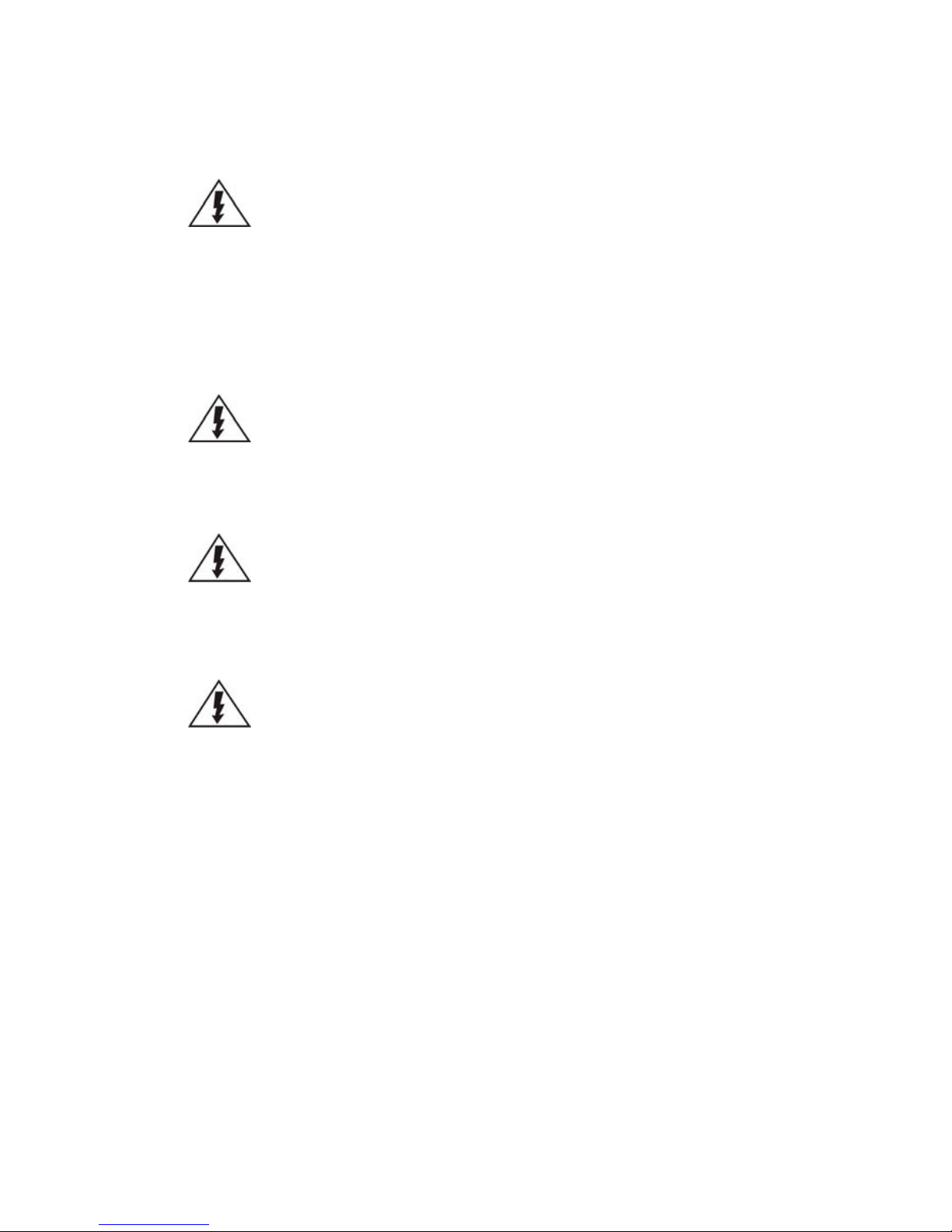
Chapter 2. Hardware Overview
2.1 Front Panel
Function
1. LCD Display
Connect the display
2. Enter Switch
Use this switch for confirmation
3. Select Switch
Use this switch for selection
4. LED Indicators
Indicates the status
5. Power Switch
Powers up the system
6. Front USB Connector
Connects external accessories such as mouse,
keyboard or other external devices.
Page 20
20
2.2. Rear Panel
Function
1. Power Socket
Used for connecting power cable.
2. e-SATA Port x1
Used for connecting the SMR with e-SATA drives.
3. USB Port x4
Used for exporting video clips as evidence support to external
storage devices.
4. LAN Port x2
(GbE Ethernet port)
Used for connecting the system with the network. Note that for
single LAN Mode, use LAN1
5. Restore Button
Use for reset the system to factory default. For details, please
refer to the table below.
6. VGA Port
Used for attaching an external monitor to the system.
7.12V DC Power Port
Used for connecting power cable.
8. Kensington Lock-hole
For use with a Kensington lock. Please refer to your Kensington
lock for instructions.
9. COM Port
Used for connecting various devices, such as a mouse, modem,
network, printer and so on.
10. HDMI Port
Used for connecting audio/video devices such as video projectors
and DVD players.
11. USB Port x2
Used for exporting video clips as evidence support to external
storage devices.
12. Safety Switch
Used for preventing injury if someone inadvertently attempts to
open the machine. Please make sure it’s on after the power cable
is attached to the power socket.
13. Audio Ports
Used for attaching audio devices such as headphones and
speakers.
Page 21
21
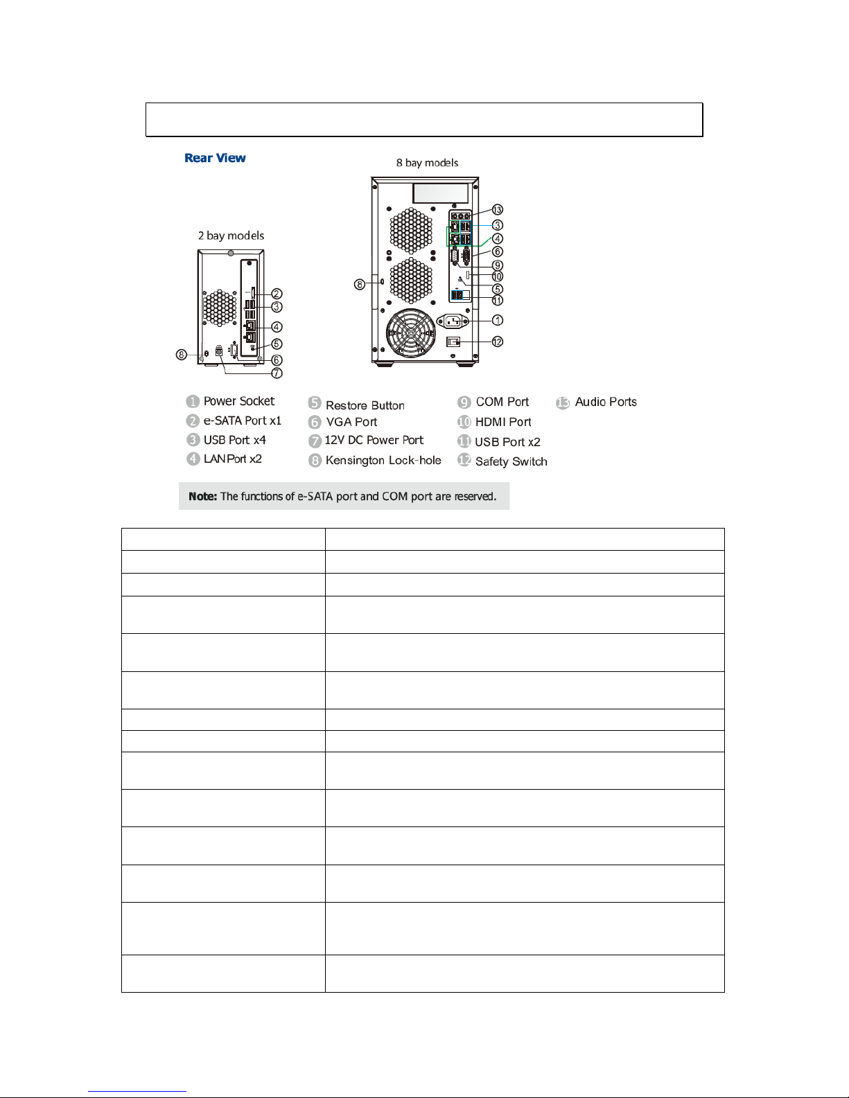
2.3. Hard Drive Designation
The hard drive arrangement for each system is shown below. The general
alignment is from left to right and/ or top to bottom in numeric order.
SMR2000 Series
SMR8000 Series
Page 22
22
2.4. LED Definitions
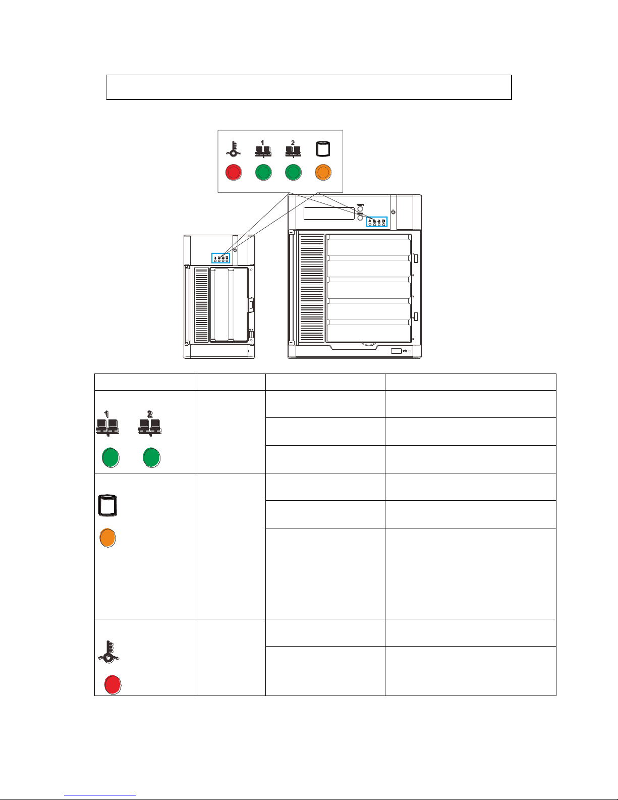
2.4.1. Desktop System Front Panel LEDs
Name
Color
LED Status
Function
Network
Green
On
Indicates that power is on and
network is connected.
Off
Indicates that network is
disconnected.
Blink
Indicates that network activity
is in progress.
HDD
Amber
On
Indicates that the hard drive can
be accessed.
Indicates that a hard drive
read/write error occurred.
Blink
Indicates one of the followings:
(1)Disk volume creation is in
progress.
(2)Online RAID level migration is
in progress.
(3)RAID rebuilding is in progress.
System
Red
On
Indicates the system fan is
malfunctioning.
Blink
Indicates that system is starting
up.
Page 23
23
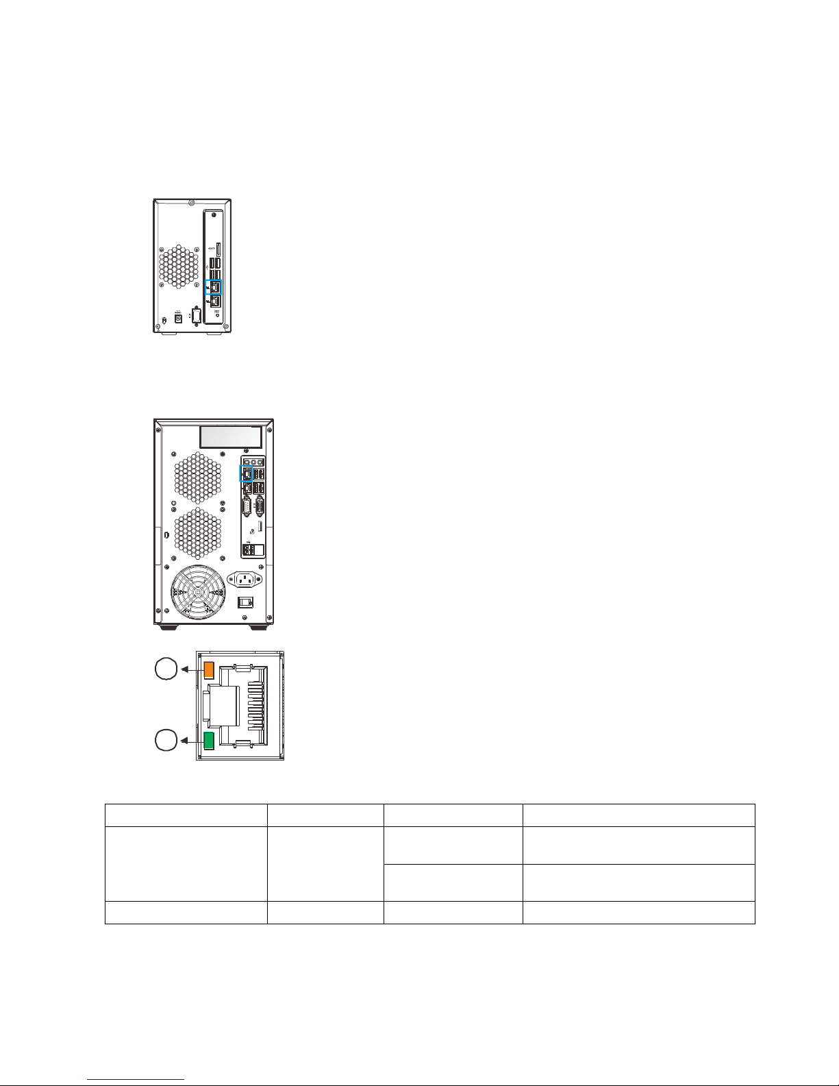
2.4.2. Rear Panel Ethernet LED
SMR2000 Series
1
2
8000 Series
1
2
RS 232/485
1
2
Name
Color
LED Status
Function
1. Link Status LED
Green
On
Indicates that the connection is
established.
Off
Indicates that the connection is
not established.
2. Activity LED
Amber
Blink
Indicates data transfer activity
Page 24

24
Chapter 3. Software Overview
3.1. Software Introduction
Video Management Software (VMS) is a highly modular and powerful video and
hardware management suite that incorporates Server recording, management, and
video monitoring and playback functionalities to serve the core purposes of a video
surveillance system.
It operates in a client-server mode: The Local Client and Local Domain Server run
for standalone SMR/NVR/VMS Server, while the Remote Client receives live video
streams and event video playbacks from LAN or Internet. All administrative tasks
are performed on the Client. The client software provides the ability to monitoring
and playback recorded videos from multiple cameras. And for users having multiple
SMR/NVR/VMS Servers, Surveon Control Center (SCC) (its main functions are the
same with the VMS) can be utilized to manage over the domain infrastructure.
Page 25

25
3.2. Module Framework
VMS/NVR Server
Combines video recording, archival and retrieval functionalities for
individual servers/standalone PCs.
Serves as the connection point for client stations.
Local Domain Server
The interface between the VMS/VI Servers and any clients.
User authentication server.
Local Client
Local access, VMS Client installed on standalone PCs/NVRs for live
video monitoring, event recording playback access and VMS system
configuration.
Remote Client (full functions)
Remote access, VMS Client installed on remote PCs for live video
monitoring, event recording playback access.
Serves as the default configuration point for NVR2000 series, which do
not have a Local Client.
Web Client (for simple use)
Remote access, an ActiveX application (OCX) installed on remote PCs
for live viewing and event playbacks through the web browser.
SPhone Client (for simple use)
SPhone Client installed on iOS/ Android devices for basic live viewing.
Web Server
Allows user to access the live video stream, PTZ control and event
recording playbacks through Microsoft Internet Explorer 7.0 (or higher)
after the Web Clients components are downloaded.
VI Server
The video intelligence processing point for a VMS solution.
Preinstalled on SMR/NVR Server, and optional on a separate server/PC
(VMS).
SCC Domain Server
Allows centralized control over multiple Trusted VMS Server points and
connections from multiple clients.
SCC Client
Page 26

26
Software capable of accessing multiple Trusted VMS Servers through
the SCC Domain Server
Page 27

27
3.3. System Architecture
VMS operates in scalable client - server architecture. This architecture can be
divided into three types: (1) Standalone Server (2) Standalone Server + Remote
Client (Web Client/SPhone Client) (3) Multiple Servers + SCC Client.
These are the hardware requirements for using PCs as Server or Client.
VMS Server + Client
Support NVRs
≥ 32CH
16~32CH
≤ 16CH
OS
64-bit :
Windows 7 Professional, Enterprise, Ultimate
CPU
Intel Core i7‐980X or
above
Intel Core i7‐860
or above
Intel Core i5‐650
or above
Memory
4 GB or above
Display
nVidia GeForce GTX660 2GB or above
Hard Drive
SATA 7200 RPM, 500 GB or above
Network
1 Gbps or above
Remote Client
OS
64-bit :
Windows 7 Professional, Enterprise, Ultimate
CPU
Intel Core i7‐980X
or above
Intel Core i7‐860
or above
Intel Core i5‐650
or above
Memory
4 GB or above
Display
nVidia GeForce GTX660 2GB or above
Hard Drive
SATA 7200 RPM, 500 GB or above
Network
1 Gbps or above
VMS Server Only
OS
64-bit :
Windows 7 Professional, Enterprise, Ultimate
CPU
Intel Core i3‐530 or above
Memory
4 GB or above
Display
On board (generic) 256MB or above
Hard Drive
SATA 7200 RPM, 500 GB or above
Network
1 Gbps or above
Page 28
28
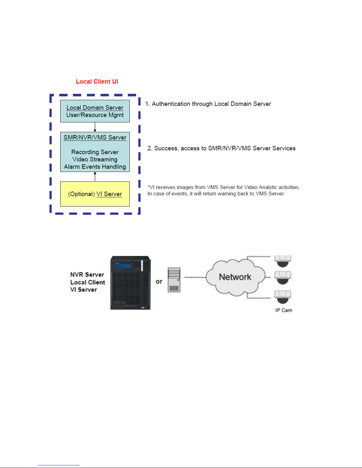
3.3.1. Standalone Server (Client-Server All-in-One)
For users with standalone Server, the Local Client UI is used to manage NVR
Server services:
※Application:
The Server, IP cameras are all in the same LAN.
Use NVR as Server
No installation needed.
Use PC as Server
Install both the VMS/NVR Server and VMS Client on a PC:
Insert the VMS/IPCAM product CD. Click VMS Suite on the menu to start the
installation. Choose Typical Setup. If you don’t need video analytic functions,
Advanced Setup can be selected to uncheck the VI Server.
Page 29
29
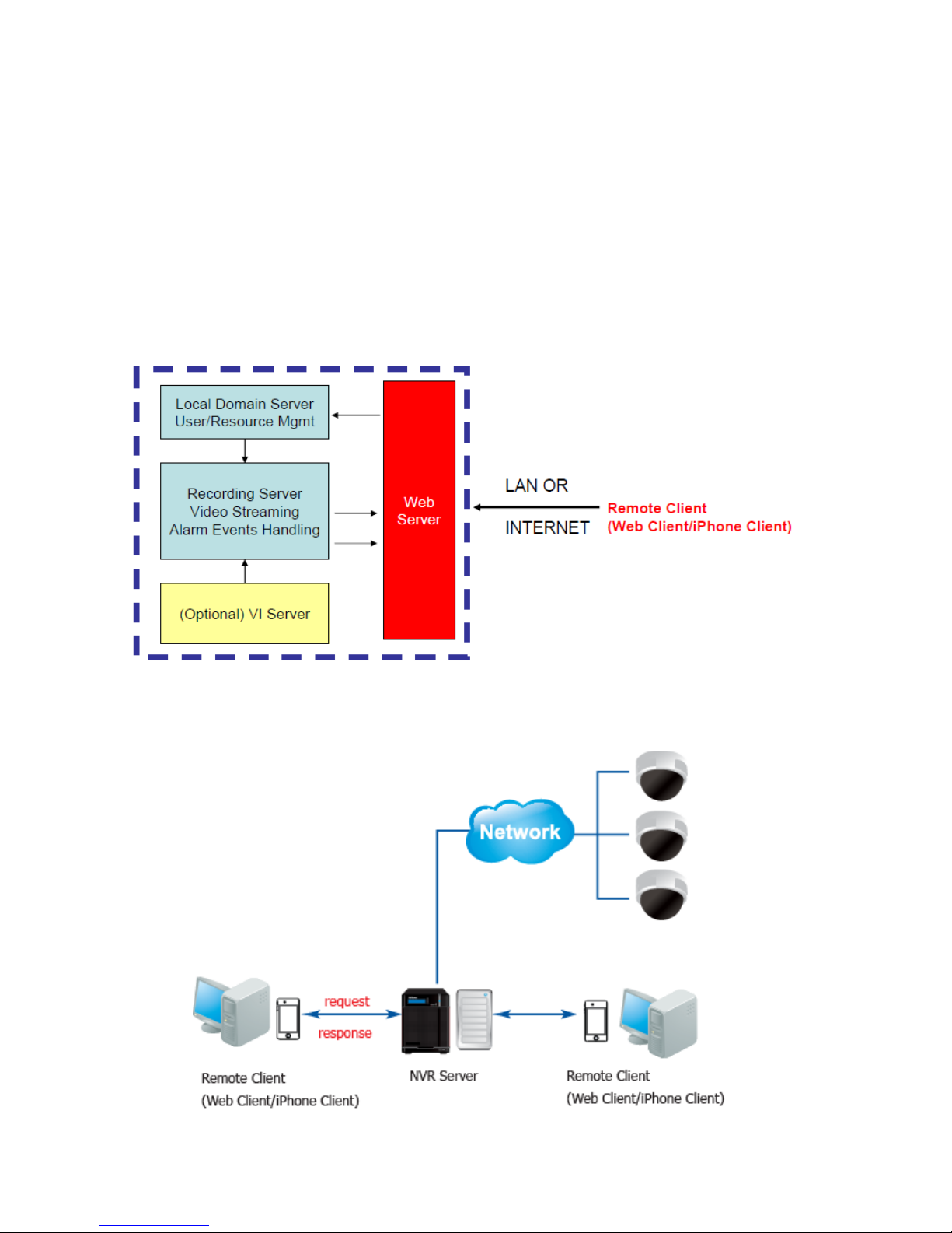
3.3.2. Standalone Server + Remote Client (Web Client
/ SPhone Client)
For remote users to connect to SMR/NVR Server, a remote access, VMS Client
installed on remote PCs is needed for live video monitoring, event recording
playback access.
Also, the Web Client, an ActiveX application (OCX) can be used for basic live
viewing and event playbacks through the web browser, while SPhone Client can
be used for basic live viewing on iPhone/Android devices.
Application1: Internet
The Server, IP cameras and the PC/Mobiles are all in the same LAN.
Page 30

30
[NVR Server]
Use SMR/NVR as Server
No installation needed.
Use PC as Server
Install the VMS/NVR Server on a PC:
Insert the VMS/IPCAM product CD.
Click VMS Suite on the menu to start the installation.
Choose Advanced Setup to uncheck the VMS Client.
If you don’t need video analytic functions, the VI Server can also be unchecked.
Install the Web Server on the PC:
Insert the VMS/IPCAM product CD.
Click Browse CD/DVD in the menu.
Double click WebServerSetup.exe to start the installation.
[Client]
Install the VMS Client on PCs:
Insert the NVR/SMR product CD.
Click VMS Client on the menu to start the installation.
Install the Web Client on the PCs (Optional):
Launch Microsoft Internet Explorer 7.0 (or above) and enter your VMS Server IP
address + “/webclient” in your web browser’s URL location, eg.
http://172.18.6.9/webclient to download the Web Client application.
Install the SPhone Client (Optional):
Download the SPhone Client from App Store on the iPhone desktop.
Install the SPhone Client (Optional)
Download the SPhone Client from App Store on the Andriod phone desktop.
Note: Please refer to Installing the VMS and Installing the Web Client for details.
Page 31

31
Application 2: Internet
The Server, some of the IP cameras and the PC are all in the same LAN, while
the other IP cameras are installed in remote location with Public IP.
3.3.3. Multiple Servers + SCC Client
For users with multiple SMR/NVR Servers, SCC Client UI is used to manage over
the domain infrastructure.
Page 32

32
Application3: Internet
(1) The Servers, IP cameras and the PCs are in LAN A.
(2) Some IP cameras are installed in LAN B, which is behind a different router in a
remote location.
(3) Users are allowed to connect the SMRs/NVRs from remote PC over the Internet.
CMS Client
NVR
Server
VI Server
CMS Domain Server
CMS Client
Multiple Servers + CMS Client
NVR
Server
NVR
Server
[NVR Server]
Use SMR/NVR as Server
No installation needed.
Use PC as Server
Install the VMS/NVR Servers on PCs:
Insert the VMS/IPCAM product CD.
Click VMS Suite on the menu to start the installation.
Choose Advanced Setup to uncheck the VMS Client.
The VI Server can also be unchecked, if you don’t need video analytic functions.
[VI Server] (Optional)
You can choose to install the VI Server only on a standalone PC to manage the
video intelligence data.
Insert the VMS/IPCAM product CD.
Click VMS Suite on the menu to start the installation.
Choose Advanced Setup to choose VI Server only.
Page 33

33
[SCC Domain Server]
Install the SCC Domain Server on a PC:
Insert the NVR/SMR product CD.
Click SCC Suite on the menu to start the installation.
Choose Advanced Setup to select the SCC Domain Server only.
[SCC Client]
Install the SCC Client on PCs:
Insert the NVR/SMR product CD.
Click SCC Suite on the menu to start the installation.
Choose Advanced Setup to select the SCC Client only.
Note: (1) For users don’t have Surevon SMR/NVR series, please contact your
dealer for the SCC installation file. (2) The SCC Domain Server can also
be installed together with the SCC Client in the same PC by choosing
Typical Setup. (3) Please refer to Installing the VMS and Installing the
SCC for details.
Page 34

34
3.3.4. Network Requirements
In order to preserve enough bandwidth for surveillance video, a surveillance
network is presumed to be free of user/business traffic. Server software
currently supports Class B and Class C type addresses. Currently the Server
software only searches for Servers on the same subnet. Cameras should also
reside on the same subnet.
Opening Ports
If access through a firewall in a local network is required, try opening the
following ports: SMTP (25), HTTP (80), FTP (20, 21), OMNI (2809), HTTPS (443) and
RTSP (554, 8554.). Other ports should also be opened while using port forwarding
to access the VMS Server: Stream Port (9090), Doman Data Port (9060), Log
Download Message Port (15507) and Log Download Data Port (9080).
Access through a firewall
Use port forwarding to access
SMTP (25),
HTTP (80),
FTP (20, 21),
OMNI (2809),
HTTPS (443),
RTSP (554, 8554.)
Stream Port (9090),
Doman Data Port (9060),
Log Download Message Port (15507),
Log Download Data Port (9080)
Note: Please refer to Port Forwarding Section for more details.
Warnings / Precautions
If the Server and a VMS client reside on separate subnets, please set up gateway,
VLAN, or cross-subnet routing to bridge surveillance traffic. Please consult with
a network administrator for problems with network setups. A VMS client needs
to be rebooted when network settings are changed.
Page 35

35
3.4. Port Forwarding
Port forwarding is a name given to the combined technique of:
1. Translating the address and/or port number of a packet to a new
destination.
2. Possibly accepting such packet(s) in a packet filter (firewall).
3. Forwarding the packet according to the routing table.
To illustrate its concept, two computers on the Internet that communicate with
each other using TCP/IP or UDP/IP protocols(though the process is not limited to
these) utilize ports to identify the opposite connection points of each other where
the data packets supposed to go to. In order to communicate, each computer
knows the port of another computer (in addition to IP address) and sends the data
to that port. Port forwarding forwards these ports in such a way that when one
computer sends data to the specific port of another computer, the data is actually
sent to a different port. This allows remote computers to connect to a specific
computer or service within a private LAN.
In a typical residential network, nodes obtain Internet access through a DSL or
cable modem connected to a router or network address translator (NAT/NAPT).
Hosts on the private network are connected to an Ethernet switch or communicate
via a wireless LAN. The NAT device's external interface is configured with a public
IP address. The computers behind the router, on the other hand, are invisible to
hosts on the Internet as they each communicate only with a private IP address.
When configuring port forwarding, the network administrator sets aside one port
number on the gateway for the exclusive use of communicating with a service in
the private network, located on a specific host. External hosts must know this port
number and the address of the gateway to communicate with the network-internal
service.
When used on gateway devices, a port forward may be implemented with a single
rule to translate the destination address and port. The source address and port are,
in this case, left unchanged. When used on machines that are not the default
gateway of the network, the source address must be changed to be the address of
the translating machine, or packets will bypass the translator and the connection
will fail.
Page 36

36
3.4.1. Port Forwarding for Accessing VMS Server
To enable port forwarding for accessing VMS Server, please follow the steps below:
1. Do Router Port Mapping for VMS/SMR Server
Go to VMS Setup > Network > Port Mapping in VMS after it is installed.
Page 37

37
A Router Port Mapping window will prompt for entering port numbers. Please put
in the numbers as listed below:
Stream Port: 9090
Login: Port: 2809
Doman Data Port: 9060
Log Download Message Port: 15507
Log Download Data Port: 9080
2. Open Ports on the Router
Host Ports: The private ports that the internal VMS/SMR Server use, which are
unchangeable.
Global Ports: The public ports for remote clients to connect to the internal
VMS/SMR Server. The Global ports are changeable, but the simplest way is to
make them the same with the host ports.
Page 38

38
Please open the listed ports on your router:
(When the option “Enable Automatic Upnp Mapping” is selected, this step can be
skipped.)
Port(Host/Global Port)
Protocol
Port Number
Domain Message Port
UDP
9050
Domain Data Port
TCP
9060
Login Port
TCP
2809
Stream Port
TCP
9090
Log Download Message Port
TCP
15507
Log Download Data Port
TCP
9080
Note: Camera port (default: 80) and stream port (default: 6002) for accessing
cameras should be opened while VMS/SMR Server and the cameras and are
not in the same LAN.
Page 39

39
Chapter 4. Installation
4.1. Before You Start
4.1.1. Checklist for Operating Environment
Users need to prepare the following devices to set up the surveillance system.
Network Video Recorder
THE SYSTEM series
IP Camera
Network Cameras (such as CAM2441)
Network
Existing LAN, Switch, Router or Hub
(please see the Network Topology below)
Storage
Hard Drives
Note: The hard drives should be purchased separately.
4.1.2. Checklist for Network Topology
Make sure you have the right switch/hub for your environment. Either of the
following options will work.
Common Topology
Reference Product
Existing LAN
LAN Switch with DHCP Server
Office LAN
Router
LAN Switch with build-in DHCP Server
D-Link DIR-130
Switch/Hub
No DHCP Server(refer to the Note below)
D-Link DES-1108
Note: For devices without DHCP Server function, please refer to Configuring DHCP
Service Section.
Page 40

40
4.2. Hard Drive Installation
4.2.1. Hard Drive Installation Prerequisites
Purchase hard drives having the same capacity and using same interface with the
pre-installed ones.
4.2.2. Inserting Hard Drive into Drive Tray (Desktop
Series)
1. Open the front panel of the SMR system.
2. Press the release button (indicated by the blue arrow) on the bezel,
the bezel panel should open automatically and gently pull out the
hard drive tray.
Release button
3. Place the hard drive into the drive tray. Make sure the hard drive’s
interface connector is facing the open side of the drive tray and its
label side facing up. Adjust the drive’s location until the mounting
holes in the drive tray are aligned with those on the hard drive.
Secure the drive with four supplied flat head screws.
Page 41

41
4. With the tray bezel open, insert the hard drive and tray into the
system enclosure.
5. Close the tray bezel.
6. Use the small flat blade screwdriver to turn the bezel lock from the
unlock to lock position.
7. Repeat above steps to install other hard drives.
8. Close the system front panel when you are done installing hard drives.
Page 42

42
4.3. System Connections
Connect cables to the rear panel ports as follows:
SMR2000 Series
1
2
8000 Series
1
2
RS 232/485
Page 43

43
Insert mouse, keyboard or other external devices to the USB port (blue
rectangles) for operating the Video Management Software (VMS).
Insert the LAN cable to the upper LAN port (blue circles) to connect the
SMR to a local network where your IP cameras reside.
(Connection to analog cameras is also available via an IP encoder.)
Connect an external monitor capable of 32bit or higher color quality to the
VGA Port (red rectangles) to view the VMS interface.
Page 44

44
4.4. Powering up SMR
4.4.1. SMR Systems
1. Attach the power cable to the power socket on the rear panel.
2. (SMR8000 Series) Make sure the safety switch on the rear panel is switched
to the “-” side, which means that it is turned on.
3. Press the Power Switch.
4. See if the System LED is blinking, which means the system is starting up.
5. See if the Network LED has turned green, which indicates power is on
and network is connected.
6. See if the HDD LED is on, which means the hard drive can be accessed.
7. (SMR8000 series) The Server name and the IP address will be shown on the
LCD screen.
SELECT
ENTER
Server
172.18.6.179
Page 45

45
4.5. Logging into SMR Series
The Local Client will prompt for the following information after the system Series
system is powered on:
Username: The username of the domain, which is always admin.
Password: The password of the domain. Default password is admin.
Auto Login: Check this option and you do not have to input the username and
the password again when logging in next time.
Click Login after the password is entered.
Page 46

46
4.6. Run the Install Wizard
When you run the system series for the first time, you need to go through the
following steps within the Install Wizard after logging in.
1. Welcome: Use the dropdown list to select the language for the VMS. Click
“Next” to go to the next step Storage Check.
Page 47

47
2. Storage Check: the system will auto detect the number of installed hard disk drives.
Check if the detection result is correct, if yes, check ”Yes and proceed to the next
step”. Click “Next” to go to the next step Create Your Storage Pool.
If the detection result is not as expected, shutdown the system and make sure all the
drives are installed properly. After checking, restart the system to run the install
wizard.
Contact your system administrator, if this error occurs again.
Page 48

48
3. Create Your Storage Pool: Select the best storage configuration for the system.
These are the RAID options.
RAID Level
RAID
Description
Min.
HDD
HDD
Used for Storage
No Protection,
Maximum Capacity
(Non-RAID)
No protection, but maximum
capacity.
2
All of HDDs
Good Protection
(RAID 5)
Use 1 disk to store the parity
function data to provide fault
tolerance.
3
HDD number
minus 1
Better Protection
(RAID 6)
Used 2 disks to store the parity
function data to provide fault
tolerance.
4
HDD number
minus 2
Best Protection
(RAID 1)
Best protection. Your data will
be mirrored.
2
Half of HDDs
Please seek for professional help, if you are not sure how to select the RAID level.
Page 49

49
3.1. After the selection is done, a confirmation will be prompted as below.
Click “Create”, if the statement shown is correct.
4. Initialize Your System: This act will take a few minutes to complete. Once it is
done, the system will reboot automatically.
Page 50

50
5. System Basic Settings: You can change or use the default password.
Check the “Use Default Password” option, if you wish to keep the default password.
If you want to change the password, input a new password and confirm the newly
created password.
Click “Next” to go to the next step Setup Time.
Page 51

51
6. Setup Time: Time setup should be done correctly, otherwise some of the functions
will be affected. Set up the time zone before setting up the time.
Click “Next” to go to the next step Recording Policy.
Note: Date / Time should be set correctly before recording.
Page 52

52
7. Recording Policy: Select the best profile for your scenario to have a balanced
resource usage for the quality of recording and local display.
• When “Always recording” is selected, every image will be recorded.
• When “Motion recording” is selected, only motion detected images will be recorded,
and approximately 25%~60% of storage can be saved according to the levels of motion
detection you have set.
Recording and Local Display Profile Selection:
•When “Standard mode” is selected, the system will not set limitations on the
recording and local display.
•When “High Quality Viewing Mode” is selected, the system will suppress the
resources on the local display to have the recording quality enhanced.
•When “Recording Capacity Maximized Mode” is selected, the system will close the
resources on the local display to maximize the recording quality.
Click “Next” to go to the next step Setup Your Network.
Page 53

53
8. Setup Your Network:
Tick the option “Obtain An IP Address Automatically”. The system will detect your
network environment automatically to see if there is a DHCP server and generate an IP
address for you.
You can also select “Input The IP Address Manually” to set up the IP address
manually.
Make sure there is no DHCP server in the network environment before ticking the
option “Auto Assign IP Address For Cameras (Make this NVR as a DHCP server)” to
make this SMR as a DHCP server. Ask your IT engineer for help, if you are not sure how
to set up.
Click “Next” to go to the next step Add Cameras.
You can click “Skip” if you wish to set up the network settings later.
After selecting “Skip”, a confirmation window will appear. Click “Shutdown” to turn
off the system.
When you turn on the system, it will take you back to this step.
Page 54

54
Warning: Make sure that only 1 DHCP server is activated in your system,
otherwise it may cause network errors.
Note: You can also change the network settings, once you’re logged in to the
Local Client. Go to Setup > Network > DHCP Server for the network configuration.
Page 55

55
9. Add Cameras
Select “Add Cameras [Simple Mode]” to add cameras by auto scan.
After selecting, you will see the list of connected cameras.
Select the cameras you’d like to add and select “Add Selected” and then click
“Finish” to complete the installation and exit the Wizard.
Note: You may reboot the cameras to refresh their IP addresses from the DHCP
server, if some of the IP addresses are shown the same or the cameras can not
be reached.
Page 56
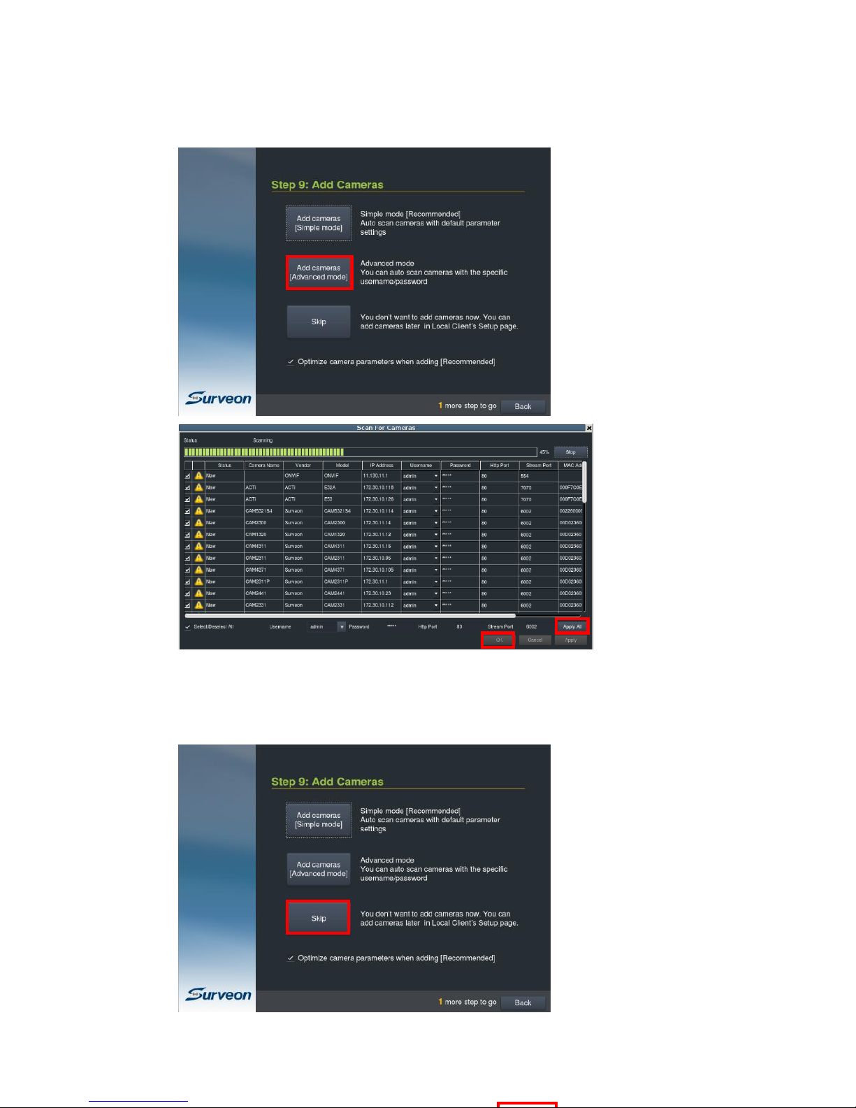
56
or “Add Cameras [Advanced Mode]” to add cameras by auto scan and with editable
parameters.
You can also click “Skip” to leave this step, if you wish to add cameras later in the
Local Client’s Setup page.
Page 57

57
Click “Skip”, a window will prompt to ask for confirmation.
Click “Shutdown” to shutdown and start from this step next time.
Click “Finish” to close this window and the system will be directed to the Local
Client.
When the option “Optimize camera parameters when adding” is not selected, a
warning will show up, confirming your wish not to optimize the cameras. Check the
option “I agree to disable camera parameter optimization” if you really to skip the
camera optimization.
Note: The cameras can also be added, after logged in to the Local Client.
Refer to the Local Client user manual Chapter 5.2. Adding Cameras to the Server
for more details.
Page 58

58
Note: After the installation is done, the system will optimize the connected cameras
and the settings of resolution, FPS and bit rate might be different from your
operation plan. In this case, please change the camera setting after adding
camera.
After the wizard installation is done, you will see the Live View page from the Local
Client. Please refer to its user manual for the system Series Local Client Operation.
Page 59

59
Chapter 5. Basic System Settings
5.1. Storage Management
1. To access the information about the drives configured in your Server, click Setup
to bring out VMS Setup window and then select Recording to see and click
Storage option for Storage Manager.
Page 60

60
2. All available Logical Drives, as well as their sizes, free space, and status will
appear. Click target drive and then Setting to set the log and location for
saving the video recordings.
3. Click the target drive first and then Settings. In “General” tab, click Check.
4. Choose the RAID level, and then click Create Logical Drive to create the
RAID configuration.
Page 61

61
5.2. Adding Cameras to the Server
Cameras can be added to the Server in two ways: via an automatic scan or by
manually inputting the camera information.
5.2.1. Automatic Scan for Cameras
Right-click on the camera to bring out the setting menu and select Scan for
Cameras.
1. The system will respond by beginning an automatic scan. Once the scan is
complete, the cameras that can be added to the Server will be displayed.
Information available for each camera will include:
Page 62

62
Name – The default camera name (Make/Model)
Status – The camera will display New if it has not been added to
this Server, otherwise it will display Assigned.
IP Address
MAC Address
Vendor - Including ACTI, Afreey, AXIS, Arecont, BOSCH, Dahua,
Dynacolor, EDIMAX, EverFocus, HIKVISION, IQinvision, JVC, LG,
Panasonic, Surveon, and ONVIF.
Model
2. To add a camera to the system, check the box by the camera entry. You may
also check the Select All box at the bottom of the window to select all the
cameras found.
Enter the username and password, and press Apply Selected. Click OK to
add the selected cameras to the Server.
The following windows will prompt for validation.
Page 63

63
5.2.2. Manually Adding Cameras
To manually add a camera to the Server:
Right-click on the camera to bring out the setting menu and select Add
Camera.
2. In the camera window fill out the following information:
IP Address
Camera Port – This value will automatically populate with the
default value for the Vendor and Model selected.
Vendor - Including Including ACTI, Afreey, AXIS, Arecont, BOSCH,
Dahua, Dynacolor, EDIMAX, EverFocus, HIKVISION, IQinvision, JVC,
LG, Panasonic, Surveon, and ONVIF.
Page 64

64
Stream Port – This value will automatically populate with the
default value for the Vendor and Model selected.
User Name – This value is not always required.
Password – This value is not always required.
Camera Name – It is recommended you change this value if you
have more than one camera of this make/model.
Camera Description
Page 65

65
5.3. Setting Recording Schedule
5.3.1. Recording Schedule
Click to bring out VMS Setup window and select Recording and then
Recording Schedule.
1. The schedule grid corresponds to every hour in the week. Click on one of
the 4 recording methods and then click on the grid area to “paint in” the
method for the corresponding hour.
Page 66

66
2. Click the Apply button to apply the schedule and OK to exit the dialog.
Page 67

67
5.4. Setting up Live View
An important part of monitoring your surveillance network is to have the right views
so that you will have the optimum viewing angle to discern a situation.
The default view setting is 4x4.
From the Camera List, you can click and drag each camera into separate frames.
The camera output will be displayed in the frame.
Page 68

68
Chapter 6 Live View
Live viewing is a crucial part of any surveillance system. Having the right view can
be the crucial difference between catching an event as it happens and missing it
altogether. VMS provides powerful tools to manage the viewing experience to help
ensure that monitoring personnel are always on top of any event.
6.1. Live View Window Overview
The live view window is split into 10 distinct parts:
1. Live View / Playback Selection Tabs – Allows users to choose live view
and playback mode.
2. Camera List – Lists all the connected cameras.
3. Snapshot – Take a snapshot of the current camera image.
4. Volume Control – Control the volume.
5. Live View Control – Interface for interacting with PTZ-enabled cameras.
6. Log - This area contains system, video, storage, network status
information.
7. Alarm – When triggered, the icon will flick with a red colored alarm
.
Page 69

69
8. Details – List all the detailed logs for review, query and export.
9. Button Area - This area contains the buttons to change views, enter the
full screen mode, go to the next/previous page, go home and auto page
flip between pages.
Full screen mode
Viewing screen modes
Auto page flip between pages
When there are more than 1 live
view page, click these buttons
to go to the next / previous
page.
Select this icon to have better
views for fisheye camera
Select according to the way your
fisheye is installed to have a best
viewing result, Ceiling Mount,
Table/Floor Mount or Wall Mount.
The distorted hemispherical
image of the fisheye camera can
be converted into a
conventional rectilinear
projection , a split-
window , a 4 split-
window with 3 enlarge
windows and 1 original image
window, an enlarged
window and the original fisheye
view .
Page 70

70
E-map
Send to the Secondary Display
Date and time
Signed in User Account
Logout
About contains version and
product information
Enclosed with the user manual
Setup button
Shutdown button
10. Main View Area – This area contains the actual video feed(s).
Page 71

71
6.2. View Setup
6.2.1. Switching Between Different Screen Divisions
Creating and Using New Screen Divisions
When a view is created, it has a default screen division setting, however when using
the view, it may be useful to change the number of screen divisions. This does not
create a different view, but divides the existing view into a new set of divisions.
To perform this function within the view, simply click the button corresponding to
the view that you want to use. The buttons are located in the area above the main
view window.
After you have clicked on the desired view, the cameras will be divided into
separate pages in the selected view; the formula is 36/selected view number. For
example, a one view will have a 36 pages of views and a 1+5 view will be 36/6, 6
pages of views.
Auto-flipping Pages
When multiple pages of screen divisions exist, you may choose to automatically flip
between the pages by clicking on the button. Clicking the button again will
end the automatic flip function.
Screen Division Page Use
The page number is displayed to the right of the view buttons. Clicking on the
arrow button to the right of the page number or clicking on the current screen
partition button will scroll through the pages in order. Clicking on the arrow button
to the left of the page number will scroll through the pages in reverse order.
Page 72

72
Fisheye View
Click the Fisheye button in the button area when using a fisheye camera. This will
bring out a selection of views for fisheye camera to have better view results.
Select according to the way your fisheye is installed to have a best viewing result,
Ceiling Mount, Table/Floor Mount or Wall Mount.
Icon
Description
Reference
conventional rectilinear
projection, panorama view
split-window, horizontal
view
4 split-windows: 3 enlarged
view windows and 1 original
fisheye window.
Place the different colored
boxes in the original fisheye
window on the upper right
corner to have detailed
views projected on the other
viewing windows.
Page 73

73
1 enlarged view window and
1 an original fisheye window.
Place the colored box in the
original fisheye window on
the upper right corner to
have a detailed view
projected.
original fisheye view
E-map
Click the E-map button in the button area to open an existing E-map or create an E-
map.
When there is an existing E-map, the E-map will be shown as below. You can click
the set camera on the map to see its surroundings. If there is an alarm, the set
camera on the E-map will begin flicking and you can have a better idea where the
event took place.
Page 74

74
When there is no E-map stored, the system will ask you to add an E-map. Follow
the steps below to create an E-map.
1. Prepare layout drawings or a map of the area being surveyed.
2. Click the Add button to bring out the Add Map window.
Page 75

75
3. Click the Browse button to open a windows dialog. Select your map and
click the Open button. The drawing will be stored in the Server.
4. Enter a name for the map in the Map Name field.
5. Click Save. Once successfully added, an E-map node will appear.
6. Go to the Camera List tab to drag and drop the cameras to the desired
location on the E-map to complete the E-map creation.
For camera relocation, click to select the cameras and then the
selected camera can be moved.
Go to VMS Setup > System > Map Editor in the setup to add another E-map
or any further setups.
Secondary Display
Click the Secondary Display button in the button area when you have the second
monitor, the view will be sent to the secondary display.
Page 76

76
6.3. Functionality Within Views
Right clicking an active window will cause a function list to appear. These are
settings and functions that can be changed within the live-view window.
6.3.1. Digital Zoom
Digital zoom increases the view size without increasing resolution. The digital zoom
function can be used within any panel (even in full screen mode) with the following
steps:
1. Right-click the panel that zoom is required on, and select Digital Zoom to
activate the function. A picture-in-picture showing the whole screen
framed by a yellow box will appear.
2. Use the mouse scroll to zoom into the center of the image. Scrolling forward
will zoom in, scrolling backward will zoom out. Click the corners of the box
and drag to the area of interest. The main picture will show the digitally-
zoomed output, while the picture and picture will display the entire view.
Page 77

77
6.3.2. Instant Playback
The instant playback function gives users the ability to instantly playback up to 45
minutes of video. Right-click the video panel that playback is required on, and
select Instant Play > [Time Length] to activate the function. A popup will open
with the desired playback. Time lengths available are dependent on, and will not
exceed the pre-alarm recording time set in Pre/Post Recording .
Page 78

78
The following table explains the buttons:
Sync all the views to play videos from the same
period of time. While in the Sync mode, the view
cannot be changed.
Async, undo syn, different views can be
selected.
Snapshot
Audio volume
Time range can be set when viewing the
playback.
Full frame mode
Key frame mode
Saves video clips/Exports selected clips
Clear all the Cue-Ins and Cue-Outs
Set Cue-In marker for clip start
Page 79

79
Set Cue-In marker for clip end
Automatic reply the clip.
(From Cue-in to Cue-Out)
Starts video playback
Pause video playback
Stops video playback.
Jumps to the previous frame
Jumps to the next frame
Jumps to the previous segment
Jumps to the next segment
The play speed can be adjusted from 1x to 8x.
6.3.3. Manual Recording
When recording schedules are set, it may be necessary to manually record a video
stream, even when the schedule does not specify for recording. In this case right-
click the panel that recording is required on, and select Manual Record > [5, 10 or
30 minutes] to activate the function. The camera will record the stream for the
amount of time specified.
Page 80

80
6.3.4. Others
Image Settings
Camera image settings can also be accessed by right-clicking the panel containing
the camera video and selecting Others > Image Settings.
1. Adjust the following sliders to change the camera image:
Brightness – The overall lighting level of the image. This value can
be used to boost or reduce the apparent lighting of the image.
Saturation – The overall color intensity of the image. This value can
be used to boost or reduce overall color intensity.
Contrast – The lighting difference between dark and light areas of
the image. This value can be used to boost or reduce apparent
differences in lighting.
Page 81

81
Hue – The color cast of the image. This value can be used to
compensate for colored lighting or other color casting.
Sharpness – The edge contrast of the image. This value can be used
to make the picture appear clearer.
2. Click OK to save your changes.
Note: Camera Image Settings can also be configured by right-click the camera entry
in the Camera List below the Live View, then click Image Adjustments >
Image Settings.
Insert
The panel can be replaced with a user overlay.
To overlay an image on top of a panel:
1. Right-click the panel and choose Others > Insert > Image. The system will
prompt you to choose an image file.
2. Choose an image file, valid image types are JPEG, BMP, TIF, PNG. Click Open
to open the file.
3. The image will be displayed in the panel. Click the red X in the top-right
corner to close the image.
Page 82

82
Send to Large Channel
When the view with different sizes is selected, views in smaller divisions can be
switched to the larger division. To perform this action, right-click the panel
corresponding to the camera and choose Others > Send to Large Channel.
Reconnect
In some cases it may be necessary to manually reset the connection to a camera.
To perform this action, right-click the panel corresponding to the camera and
choose Others > Reconnect.
Remove the Camera
The Cameras can be removed by clicking Others > Remove Camera.
Page 83

83
6.4. Full Screen View
6.4.1. Entering Full Screen View
From any view, you can switch to full screen mode by clicking on the full screen
button located above the main viewing window. Optionally you may also choose to
view a single frame in full screen mode by double clicking on the frame.
6.4.2. Exiting Full Screen Mode
To exit full screen mode, hit the ESC key on your keyboard.
Page 84

84
Chapter 7. Server Setup
This section deals with Server setup procedures.
7.1. Server Settings
7.1.1. General Server Settings
The following sections deal with Server settings that can be configured under the
Server Settings menu.
1. Click to bring out VMS Setup window and select System and then select
General Server Settings.
2. A tabbed window will appear providing the following configuration tabs: Storage
Quota and Time Settings.
Page 85

85
Storage Quota
In the Minimum Free Space field, the Minimum space required for storage is
shown. The storage will be last for 30 days. Click on the items in the Position
section and use the Up and Down buttons to change the storage priorities.
Time Settings
Page 86

86
To set the server time click on the number you wish to change and enter a
value. Click OK to preserve the setting. The default time is set according to
the real-time clock on server.
Time Synchronize
To synchronize the system time with the external server, check the
option ”Automatically synchronize time with external server” to enable this
functionality. And input the IP address of the external server in the External
Server field.
Check the option “Make this NVR as an NTP server” to enable this functionality.
And check the option “Apply to all camera” to make this SMR as an NTP server
and to have camera time and SMR time synchronized.
Page 87

87
7.1.2. To perform Notification Setting
1. Click to bring out VMS Setup window and select Alarm and then
select Email Notification or SMS Notification.
2. Click Email Notification tab to continue.
2.1. You may either enter the URL (such as smtp.abc.com) or IP address of
the SMTP server that the Server will use to deliver E-mail notifications. The
SMTP server configured here must support Unicode Transformation Format-8
(UTF-8) encoding.
Page 88

88
2.2. Enter the user name for the Server email account in the Username field.
2.3. Enter the password for the Server email account in the Password field.
2.4. Enter a valid E-mail address in the Reply Address field. This address
will be the default sender listed in E-mails sent from the Server.
2.5.Enter one or more E-mail addresses in the Recipients: field. These
address(es) will receive notifications from the Server. Multiple addresses
can be entered by separating individual addresses with semi -colons “;”.
2.6. Enter the subject of your notification E-mails, e.g., Server-
xxxsite1notification in the E- Mail Title field.
2.7. Enter a short message in the large field to describe the Server or a
surveillance network.
2.8. (Optional) Click Test to send a test message to the E-mail addresses
listed.
3. Click the SMS Notification to continue.
3.1. In the Contact Number field, enter the phone numbers that will receive
SMS notifications. Be sure to include the area code, e.g., “86”, in front of
phone numbers. Use commas, “,” to separate individual phone numbers.
3.2. Use the slider bar to select a delay between the occurrence of an event
and SMS message delivery.
Page 89

89
3.3. (Optional) If a SIM PIN is required, enter the PIN code in the PIN field.
Note that applying incorrect PIN code may disable your SIM card.
Note: To change the PIN code, remove the SIM card from your GSM modem. Use
a cell phone to change the PIN code and then re -install SIM card into the
GSM modem. Changing PIN codes is not recommended because a
configuration failure may disable your SIM card.
3.4. In the SMS Content field, type a simple description to include in the
outgoing SMS messages
3.5. (Optional) Click Test to send a test message to the phone numbers
listed.
3.6. Click the Apply button to apply the changes.
3.7. Click the OK button to exit E-mail/SMS settings.
Page 90

90
7.1.3. Scheduling Recording
Click to bring out VMS Setup window and select Recording and then
Recording Schedule.
Page 91

91
The schedule grid corresponds to every hour in the week. Click on one of the 2
recording methods and then click on the grid area to “paint in” the method for
the corresponding hour.
1. Click OK to save the settings and exit the dialog.
Page 92

92
7.1.4. Storage Management
1. To access the information about the drives configured in your Server, click
to bring out VMS Setup window and then select Recording to see and click
Storage option for Storage Manager.
2. All available Logical Drives, as well as their sizes, free space, and status will
appear. Click target drive and then Setting to set the log and location for
saving the video recordings.
Page 93

93
3. Click the target drive first and then Settings. In “General” tab, click Check.
4. Choose the RAID level, and then click Create Logical Drive to create the
RAID configuration.
Page 94

94
7.1.5. Pre/Post Recording
Video streams are constantly processed and cached in memory. The Server can
trace back and preserve video/images from several minutes before and after the
occurrence of an alarm.
Click to bring out VMS Setup window and select Recording and then select
Pre/Post Recording .
The following pop-up window will appear:
In each of the boxes enter values for the Pre and Post Recording times from 1 to
300 seconds (default is 300 seconds). Click the OK button to finish the process.
Page 95

95
Chapter 8. Camera Setup
This section deals with Camera setup procedures. These options can be accessed by
right-clicking the Camera entry in the Camera List below the Live View.
8.1. Adding Cameras
Cameras can be added to the Server in two ways: via an automatic scan or by
manually inputting the camera information.
8.1.1. Automatic Scan for Cameras
To begin an automatic scan for cameras:
Right-click on the camera to bring out the setting menu and select Scan for
Cameras.
Page 96

96
1. The system will respond by beginning an automatic scan. Once the scan is
complete, the cameras that can be added to the Server will be displayed.
Information available for each camera will include:
Status – The camera will display New if it has not been added to
this Server, otherwise it will display Assigned.
Camera Name – The default camera name (Make/Model)
Vendor - Including ACTI, Afreey, AXIS, Arecont, BOSCH, Dahua,
Dynacolor, EDIMAX, EverFocus, HIKVISION, IQinvision, JVC, LG,
Panasonic, Surveon, and ONVIF.
Model
IP Address
Username
Password
Http Port
Stream Port
MAC Address
2. To add a camera to the system, check the box by the camera entry. You may
also check the Select All box at the bottom of the window to select all the
cameras found.
Enter the username and password, and press Apply Selected. Click OK to
add the selected cameras to the Server.
Page 97

97
3. (Optional) Double-click any camera entry to bring up the camera detail
page. From this page you may change the following information:
IP Address – Changing this value will affect connectivity.
Camera Port – The web access port, default is 80.
Vendor – Changing this value will affect connectivity.
Model – Changing this value will affect connectivity.
Stream Port – Default is 6002.
User Name – This value is not always required.
Password – This value is not always required.
Information
Camera Name – It is recommended you change this value if you
have more than one camera of this make/model.
Camera Description
Page 98
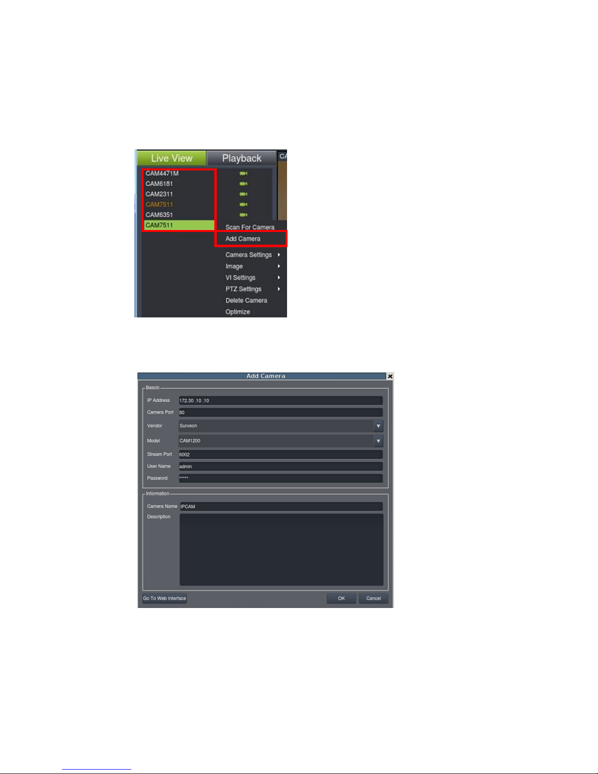
98
8.1.2. Manually Adding Cameras
To manually add a camera to the Server:
Right-click on the camera to bring out the setting menu and select Add
Camera.
2. In the camera window fill out the following information:
IP Address – Changing this value will affect connectivity.
Camera Port – The web access port, default is 80.
Vendor – Changing this value will affect connectivity.
Model – Changing this value will affect connectivity.
Page 99

99
Stream Port – Default is 6002.
User Name – This value is not always required.
Password – This value is not always required.
Information
Camera Name – It is recommended you change this value if you
have more than one camera of this make/model.
Camera Description
Page 100

100
8.2. Camera General Settings
8.2.1. General Camera Settings
Camera general settings include network connectivity settings, as well as basic
camera name, description and icon settings.
1. Right-click the camera entry and select Camera Settings > General
Camera Settings.
Or click to bring out VMS Setup window and select Camera and then
select General Camera.
 Loading...