

Page 1

SMR Series
Smart Megapixel Video Recorder
Administrator Manual
Release 2.2
Page 2

2
About This Document
This manual introduces the hardware components of SMR series and describes
how to install them. It also provides an overview of Server surveillance
functionality, and includes the functions of Video Management Software for
operating and monitoring a Server network.
Version History
Description
Date
1.0
Initial release
November 2011
1.1
1. New models are added.
2. Revise the Software Module Framework
and add the System Architecture into
the manual.
3. Add instructions for the SCC.
4. Add Software Installation section.
5. Add instructions for the Web Client.
January 2012
1.2
1. Add functionalities for SMR restore
button.
2. Update the VMS version to 2.4.7.
March 2012
1.3
New models are added.
May 2012
1.4
Update for VMS2.4.7A09
August 2012
1.5
New models are added.
January 2013
1.6
Update for VMS2.4.8
May 2013
1.7
New models are added.
June 2013
1.8
Spec updated.
August 2013
Page 3

3
1.9
New VMS FW2.5
AC 1.0 Added
August 2013
2.0
UI Modified
November 2013
2.1
Reinstallation section added
March 2014
2.2
Remote Monitoring Modified
June 2014
Page 4

4
All Rights Reserved © Surveon Technology 2014
Copyright Statement
No part of this publication may be reproduced, transmitted, transcribed,
stored in a retrieval system, or translated into any language or computer
language, in any form or by any means, electronic, mechanical, magnetic,
optical, chemical, manual or otherwise, without the prior written consent of
Surveon Technology Inc.
Disclaimer
Surveon Technology makes no representations or warranties with respect to
the contents hereof and specifically disclaim any implied warranties of
merchantability or fitness for any particular purpose. Furthermore, Surveon
Technology reserves the right to revise this publication and to make changes
from time to time in the content hereof without obligation to notify any
person of such revisions or changes. Product specifications are also subject to
change without notice.
Trademarks
Surveon and Surveon logo are trademarks of Surveon Technology Inc. Other
names prefixed with “SMR” and “EMR” are trademarks of Surveon Technology
Inc.
Microsoft Windows and Windows are registered trademarks of Microsoft
Corporation.
Linux is a trademark of Linux Torvalds.
Solaris and Java are trademarks of Sun Microsystems, Inc.
All other names, brands, products or services are trademarks or registered
trademarks of their respective owners.
Page 5

5
Table of Contents
About This Document .................................................................... 2
Version History ........................................................................... 2
Copyright Statement ......................................................................... 4
Table of Contents ............................................................................. 5
Safety Precautions .......................................................................... 19
Device Site Recommendations ............................................................ 19
Chapter 1. Product Overview ............................................................. 20
1.1. Features and Benefits ............................................................. 20
1.2. Specifications for the SMR Series ............................................... 21
1.2.1. Hardware Specifications - Desktop Series .................................. 21
1.2.2. Hardware Specifications - Rackmount Series .............................. 22
1.2.3. VMS Specifications ............................................................. 23
Chapter 2. Hardware Overview .......................................................... 25
2.1. Front Panel .......................................................................... 25
2.2. Rear Panel ........................................................................... 26
2.3. Hard Drive Designation ............................................................ 28
2.4. LED Definitions ..................................................................... 29
2.4.1. Desktop System Front Panel LEDs ............................................ 29
2.4.2. Rackmount System Front LED Panel ......................................... 30
2.4.3. Drive Tray LED .................................................................. 31
2.4.4. Rear Panel Ethernet LED ...................................................... 32
Chapter 3. Software Overview ........................................................... 33
3.1. Software Introduction ............................................................. 33
3.2. Module Framework ................................................................ 34
3.3. System Architecture ............................................................... 36
3.3.1. Standalone Server (Client-Server All-in-One) .............................. 37
3.3.2. Standalone Server + Remote Client (Web Client/SPhone Client) ....... 38
3.3.3. Multiple Servers + SCC Client ................................................. 41
3.3.4. Network Requirements ........................................................ 44
Page 6

6
Opening Ports ...................................................................... 44
Warnings / Precautions ........................................................... 44
3.4. Port Forwarding .................................................................... 45
3.4.1. Port Forwarding for Accessing VMS Server ................................. 46
Chapter 4. Installation ..................................................................... 49
4.1. Before You Start .................................................................... 49
4.1.1. Checklist for Operating Environment........................................ 49
4.1.2. Checklist for Network Topology .............................................. 49
4.2. Hard Drive Installation ............................................................ 50
4.2.1. Hard Drive Installation Prerequisites ........................................ 50
4.2.2. Inserting Hard Drive into Drive Tray (Desktop Series) .................... 50
4.2.3. Inserting Hard Drive into Drive Tray (Rackmount Series) ................ 52
4.3. System Connections ............................................................... 54
4.4. Powering up SMR ................................................................... 56
4.4.1. SMR Desktop Systems .......................................................... 56
4.4.2. SMR Rackmount Systems ...................................................... 56
4.5. Install Wizard ....................................................................... 57
4.6. Software Installation............................................................... 64
4.6.1. Installing the VMS .............................................................. 64
4.7. Starting the VMS Client............................................................ 69
4.7.1. Checking the Software Version ............................................... 70
4.7.2. Logging out ...................................................................... 70
Chapter 5. Reinstallation .................................................................. 71
5.1. Reset RAID ........................................................................... 71
5.2. Reset the Whole System .......................................................... 74
Chapter 6. Basic System Settings ........................................................ 81
6.1. Storage Management .............................................................. 81
6.2. Adding Cameras to the Server ................................................... 83
6.2.1. Automatic Scan for Cameras ................................................. 83
6.2.2. Manually Adding Cameras ..................................................... 87
6.3. Setting Recording Schedule ...................................................... 89
Page 7

7
6.3.1. Weekly Scheduling ............................................................. 89
6.3.2. Daily Scheduling ................................................................ 91
6.4. Adding Alarm Rules ................................................................ 92
6.5. Setting up Live View ............................................................... 94
6.6. Using the LCD Menu in SMR Desktop Systems ................................. 95
6.6.1. Checking the System Status .................................................. 95
6.6.2. Rebooting/Shutting Down SMR ............................................... 96
Chapter 7. Live View ....................................................................... 97
7.1. Live View Window Overview ..................................................... 97
7.1.1. Resizing and Minimizing Windows ............................................ 99
Minimizing Controls ............................................................... 99
Hiding and Showing the Explorer Area ......................................... 99
7.2. View Setup ........................................................................ 100
7.2.1. Types of Views ................................................................. 100
7.2.2. Adding a View ................................................................. 101
7.2.3. Add PAP View .................................................................. 103
7.2.4. Add Fisheye View ............................................................. 104
7.2.5. Renaming a View .............................................................. 105
7.2.6. Deleting a View ................................................................ 105
7.2.7. Sending View to a New Window ............................................. 105
7.2.8. Switching Between Views .................................................... 106
7.2.9. Switching Between Different Screen Divisions ............................ 106
Creating and Using New Screen Divisions ..................................... 106
Screen Division Page Use ........................................................ 106
Auto-flipping Pages .............................................................. 107
Exiting Different Screen Divisions .............................................. 107
7.3. Functionality Within Views ..................................................... 108
7.3.1. Digital Zoom ................................................................... 108
7.3.2. Instant Playback ............................................................... 109
7.3.3. Manual Recording ............................................................. 111
7.3.4. Preset Pan ...................................................................... 112
Page 8

8
7.3.5. Stream Selection .............................................................. 112
7.3.6. Image Settings ................................................................. 112
7.3.7. Video Ratio Adjustment ...................................................... 113
7.3.8. Inserting Overlays ............................................................. 113
Image Overlay .................................................................... 113
HTML Overlay ..................................................................... 114
7.3.9. Send to Large Channel ....................................................... 114
7.3.10. Reconnect .................................................................... 115
7.3.11. Remove the Camera ......................................................... 115
7.3.12. Onscreen PTZ Control ....................................................... 116
Pan and Tilt ....................................................................... 116
Zoom ............................................................................... 116
7.4. Full Screen View ................................................................. 117
7.4.1. Entering Full Screen View .................................................... 117
7.4.2. Exiting Full Screen Mode ..................................................... 117
7.5. E-Maps .............................................................................. 118
7.5.1. Adding E-Maps ................................................................. 118
7.5.2. Adding Sub-Maps .............................................................. 118
7.5.3. Adding Additional E-Maps .................................................... 119
7.5.4. Changing E-Map Order ........................................................ 120
7.5.5. Renaming an E-Map ........................................................... 120
7.5.6. Configuring an E-Map ......................................................... 120
7.5.7. Deleting an E-Map ............................................................. 121
7.5.8. Using the E-Map ............................................................... 121
Chapter 8. Server Setup ................................................................. 123
8.1. Server Basic Functions .......................................................... 123
8.1.1. Logging into a Server ......................................................... 123
8.1.2. Logging out of a Server ....................................................... 123
8.1.3. Renaming a Server ............................................................ 124
8.1.4. Viewing Server and Client Information..................................... 124
8.2. Server Settings .................................................................... 125
Page 9

9
8.2.1. General Server Settings ...................................................... 125
8.2.2. To perform Notification Setting ............................................. 128
8.2.3. Pre/Post Alarm Recording Settings ......................................... 130
8.2.4. Storage Management ......................................................... 131
8.3. Scheduling Recording ............................................................ 134
8.3.1. Global Scheduling ............................................................. 134
Weekly Global Scheduling ....................................................... 134
Daily Global Scheduling ......................................................... 136
8.3.2. Individual Scheduling ......................................................... 138
Weekly Individual Scheduling ................................................... 138
Daily Individual Scheduling ..................................................... 139
Chapter 9. Camera Setup ................................................................ 141
8.1. Adding Cameras .................................................................. 141
9.1.1. Automatic Scan for Cameras ................................................ 141
9.1.2. Manually Adding Cameras .................................................... 144
9.1.3. Deleting a Camera ............................................................ 145
9.1.4. Initializing a Camera .......................................................... 146
8.2. Camera General Settings........................................................ 147
8.2.1. Logging into a Camera ........................................................ 147
8.2.2. Changing the Camera Model and Vendor .................................. 147
8.2.3. General Settings ............................................................... 149
8.2.4. OSD Settings ................................................................... 150
8.2.5. Privacy Mask Settings ......................................................... 151
8.3. Camera Image and Quality Settings ........................................... 153
8.3.1. Camera Image Settings ....................................................... 153
8.3.2. Advanced Video Settings ..................................................... 154
8.4. PTZ Settings ....................................................................... 155
8.4.1. PTZ Settings .................................................................... 155
8.4.2. PTZ Preset Settings ........................................................... 156
Adding a Preset ................................................................... 156
Deleting a Preset ................................................................. 157
Page 10

10
8.4.3. PTZ Patrol Settings............................................................ 157
8.5. PTZ Controls ....................................................................... 159
8.5.1. Directional Pad ................................................................ 159
Pan and Tilt ....................................................................... 159
Zoom ............................................................................... 159
8.5.2. Functional Buttons ............................................................ 160
Speed .............................................................................. 160
Home ............................................................................... 160
Preset .............................................................................. 160
Adding a Preset ................................................................... 160
Deleting a Preset ................................................................. 160
Patrol .............................................................................. 161
Start Auto Pan .................................................................... 161
Focus ............................................................................... 161
Chapter 10. Alarms and Events ......................................................... 162
10.1. Camera VI Detection Settings ................................................ 163
10.1.1. General Motion Detection .................................................. 163
Configuring and Editing Detection Windows .................................. 163
Testing Detection Windows ..................................................... 164
Deleting a Detection Window .................................................. 164
Enabling or Disabling a Detection .............................................. 164
Opening the Help File ........................................................... 164
10.1.2. Foreign Object Detection ................................................... 165
Configuring and Editing Detection Windows .................................. 165
Testing Detection Windows ..................................................... 166
Deleting a Detection Window .................................................. 166
Enabling or Disabling a Detection .............................................. 166
Opening the Help File ........................................................... 167
10.1.3. Forbidden Area Detection .................................................. 168
Configuring and Editing Detection Windows .................................. 168
Testing Detection Windows ..................................................... 169
Page 11

11
Deleting a Detection Window .................................................. 169
Enabling or Disabling a Detection .............................................. 169
Opening the Help File ........................................................... 170
10.1.4. Intrusion Detection .......................................................... 171
Configuring and Editing Detection Windows .................................. 171
Testing Detection Windows ..................................................... 172
Deleting a Detection Window .................................................. 172
Enabling or Disabling a Detection .............................................. 172
Opening the Help File ........................................................... 173
10.1.5. Missing Object Detection ................................................... 174
Configuring and Editing Detection Windows .................................. 174
Testing Detection Windows ..................................................... 175
Deleting a Detection Window .................................................. 175
Enabling or Disabling a Detection .............................................. 175
Opening the Help File ........................................................... 176
10.1.6. Tampering Detection ........................................................ 177
Configuring Tampering Detection .............................................. 177
Testing Tampering Detection ................................................... 178
Enabling or Disabling a Detection .............................................. 178
Opening the Help File ........................................................... 178
10.1.7. Camera Motion Detection .................................................. 179
Configuring and Editing Detection Windows .................................. 179
Deleting a Detection Window .................................................. 180
Opening the Help File ........................................................... 180
10.1.8. Virtual Fence ................................................................. 181
Configuring and Editing Detection Windows .................................. 181
Testing Detection Windows ..................................................... 182
Deleting a Detection Window .................................................. 182
Enabling or Disabling a Detection .............................................. 183
Opening the Help File ........................................................... 183
10.1.9. Object Counting ............................................................. 184
Page 12

12
Configuring and Editing Detection Windows .................................. 184
Testing Detection Windows ..................................................... 185
Deleting a Detection Window .................................................. 185
Enabling or Disabling a Detection .............................................. 186
Opening the Help File ........................................................... 186
10.1.10. Going Out Detection ....................................................... 187
Configuring and Editing Detection Windows .................................. 187
Testing Detection Windows ..................................................... 188
Deleting a Detection Window .................................................. 188
Enabling or Disabling a Detection .............................................. 188
Opening the Help File ........................................................... 189
10.1.11. Tailgating Detection ....................................................... 190
Configuring and Editing Detection Windows .................................. 190
Testing Detection Windows ..................................................... 191
Deleting a Dividing LIne ......................................................... 191
Enabling or Disabling a Detection .............................................. 191
Opening the Help File ........................................................... 192
10.2. Alarm Rules ...................................................................... 193
10.2.1. Adding an Alarm Rule ....................................................... 194
Alarm Conditions ................................................................. 194
Alarm Actions ..................................................................... 202
Alarm Scheduling ................................................................. 208
10.3. Alarms View and Notification ................................................ 210
10.3.1. Live View Event Log ......................................................... 210
10.3.2. Alarm Popups ................................................................. 210
Setting Popup Sleep Time ....................................................... 211
10.3.3. Video Panel ................................................................... 212
Playback from Video Alarm Panel ............................................. 212
Tagging an Alarm Thumbnail ................................................... 213
10.4. Event Log ......................................................................... 214
10.4.1. Exporting a Log .............................................................. 214
Page 13

13
10.4.2. Searching the Event Log .................................................... 215
System Type ...................................................................... 215
Event Type ........................................................................ 215
Operation Type ................................................................... 216
Performing a Search ............................................................. 216
10.4.3. Event Log Setup .............................................................. 217
10.4.4. Log for Object Counting .................................................... 217
10.4.5. System Alarm View .......................................................... 218
Chapter 11. Search and Playback ...................................................... 219
11.1. Introduction ..................................................................... 219
11.2. Date/Time Search............................................................... 220
11.2.1. Time Selection ............................................................... 220
Recent Time ...................................................................... 220
Specified Time .................................................................... 220
11.2.2. Use of 1x/4x Views .......................................................... 221
11.2.3. Camera Selection ............................................................ 221
11.2.4. Timeline ....................................................................... 222
11.2.5. Playback ...................................................................... 224
Advanced Video Settings ........................................................ 226
Synchronized Playback .......................................................... 226
Capturing Screenshot ............................................................ 226
Capturing Video Clip ............................................................. 227
10.3. VI Search ......................................................................... 229
10.3.1. Creating a VI Search ......................................................... 229
Time Selection .................................................................... 229
Camera Selection................................................................. 230
Setting New Search Criteria .................................................... 231
10.3.2. Saving/Retrieving a VI Search .............................................. 247
10.3.3. Using the Search Results .................................................... 247
Selecting the Result.............................................................. 247
Result Playback ................................................................... 248
Page 14

14
Playback Synchronization ....................................................... 249
Capturing Screenshot ............................................................ 249
Capturing Video Clip ............................................................. 250
Logging and Noting ............................................................... 251
10.4. Event Search..................................................................... 252
10.4.1. Creating an Event Search ................................................... 252
Time Selection .................................................................... 252
Camera Selection................................................................. 253
Setting Event Search Criteria ................................................... 253
10.4.2. Using the Search Results .................................................... 254
Selecting the Result.............................................................. 254
Result Playback ................................................................... 255
Playback Synchronization ....................................................... 256
Capturing Screenshot ............................................................ 256
Logging and Noting ............................................................... 257
Chapter 12. Remote Web Client and SPhone Client for Simple Use (Optional)259
12.1. Starting the Web Client........................................................ 260
12.1.1. Checking the Software Version ............................................ 261
12.1.2. Use of 1x/4x views .......................................................... 261
12.1.3. PTZ Control ................................................................... 261
12.1.4. Playback Settings ............................................................ 262
12.2. Installing and Starting the SPhone Client on iOS Devices ............... 263
12.2.1. Installing the SPhone Client (Optional) ................................... 263
12.2.2. Starting the SPhone Client ................................................. 263
12.2.3. Checking the Software Version ............................................ 264
12.2.4. Live View/Playback on the SPhone Client ............................... 264
12.3. Installing and Starting the SPhone Client on Android Devices ......... 267
12.3.1. Installing the SPhone Client (Optional) ................................... 267
12.3.2. Starting the SPhone Client ................................................. 267
12.3.3. Checking the Software Version ............................................ 268
12.3.4. Live View on the SPhone Client ............................................ 268
Page 15

15
Chapter 13. System Setup ............................................................... 270
13.1. Home Page ....................................................................... 270
13.1.1. Entering the Home Page – VMS Server .................................... 270
Common Server Tasks ........................................................... 271
Common Camera Tasks .......................................................... 271
Common Other Tasks ............................................................ 272
Recent Key Events ............................................................... 272
System Health History ........................................................... 273
System Status ..................................................................... 273
13.1.2. Entering the Home Page – Local Domain ................................. 273
Tasks ............................................................................... 273
NVR Status ......................................................................... 275
13.2. Server Setup ..................................................................... 276
13.2.1. General Tasks ................................................................ 276
Alarm Rule Settings .............................................................. 277
View Log ........................................................................... 277
E-Map .............................................................................. 277
Global Schedule .................................................................. 277
Individual Schedule .............................................................. 277
Storage ............................................................................. 277
Pre/Post Alarm Recording Settings ............................................ 277
Email ............................................................................... 278
SMS ................................................................................. 278
Digital I/O Settings ............................................................... 278
Genera Server Settings .......................................................... 278
Joystick ............................................................................ 278
Software License Mechanism (For Local Client Only) ....................... 280
Backup (For Local Client Only) ................................................. 280
Reboot NVR Server ............................................................... 281
VI Manager ........................................................................ 282
Schedule Reboot.................................................................. 283
Page 16

16
Audio Input ........................................................................ 283
Playback Camera List Setting ................................................... 284
Playback Buffer ................................................................... 284
Auto Login ......................................................................... 284
VI Panel ............................................................................ 285
Lock Windows ..................................................................... 285
Import/Export .................................................................... 285
Customize Logo ................................................................... 286
Router Port Mapping ............................................................. 287
13.3. Camera Setup ................................................................... 288
13.3.1. General Tasks ................................................................ 288
Scan for Cameras ................................................................. 288
Add Cameras ...................................................................... 288
Delete Camera .................................................................... 289
13.3.2. Camera Settings.............................................................. 289
Image Settings .................................................................... 289
Advanced Video Settings ........................................................ 289
General Camera Settings ........................................................ 289
Edit Camera ....................................................................... 289
PTZ Settings ....................................................................... 290
Preset Settings .................................................................... 290
OSD Settings ...................................................................... 290
Compatibility Verify ............................................................. 290
Initialize ........................................................................... 290
Automatic Settings ............................................................... 290
13.3.3. Video Analytics ............................................................... 291
General Motion Detection ....................................................... 291
Foreign Object Detection ....................................................... 291
Forbidden Area Detection ....................................................... 291
Intrusion Detection .............................................................. 292
Missing Object Detection ........................................................ 292
Page 17

17
Tampering Detection ............................................................ 292
Camera Motion Detection ....................................................... 292
Virtual Fence ...................................................................... 292
Object Counting .................................................................. 293
Going Out Detection ............................................................. 293
Tailgating Detection ............................................................. 293
13.4. Ethernet I/O Box ................................................................ 294
13.4.1. General Tasks ................................................................ 294
Add Device ........................................................................ 294
Edit Device ........................................................................ 296
Delete Device ..................................................................... 296
13.5. Account Manager ............................................................... 297
13.5.1. Account List .................................................................. 297
Adding an Account ............................................................... 298
Editing an Account ............................................................... 299
Deleting an Account ............................................................. 300
13.5.2. Functional Authority ........................................................ 301
13.6. Network Parameters ........................................................... 302
13.6.1. Main Tasks .................................................................... 302
Maximum Video Connections ................................................... 302
Blacklist/Whitelist Settings ..................................................... 303
Edit NVR ........................................................................... 304
Web Server ........................................................................ 304
Multiple LAN Support ............................................................ 305
DHCP Server ....................................................................... 306
13.7. Other Parameters............................................................... 308
13.7.1. Other Tasks ................................................................... 308
Import/Export .................................................................... 308
Resolution ......................................................................... 309
Language .......................................................................... 310
Help ................................................................................ 310
Page 18

18
About ............................................................................... 310
Chapter 14. System Maintenance ...................................................... 311
14.1. Replacing the Power Supply Module (for Rackmount Series) .......... 311
14.2. Replacing a Hard drive (for Desktop Series) ............................... 313
14.3. Replacing a Hard drive (for Rackmount Series) ........................... 315
14.4. Restore Default Settings ....................................................... 317
Chapter 15. AC Device Tool ............................................................. 318
15.1. Installing the Access Control Device Tool .................................. 318
15.2. How AC Device Tool works .................................................... 322
Page 19
19
Safety Precautions
Electric Shock Warning
This equipment may cause electric shocks if not handled properly.
Access to this equipment should only be granted to trained operators
and maintenance personnel who have been instructed of, and fully
understand the possible hazardous conditions and the consequences of
accessing non-field-serviceable units such as the power supplies.
The system must be unplugged before moving, or in the even that it
becomes damaged.
Reliable Grounding
Particular attention should be given to prepare reliable grounding for the
power supply connection. It is suggested to use a direct connection to the
branch circuit. Check for proper grounding before powering on the device.
Overloading Protection
The device should be installed according to specifications. Provide a suitable
power source with electrical overload protection. Do not overload the AC
supply branch circuit that provides power to the device.
ESD Precautions
Please observe all conventional anti-ESD methods while handling the device.
The use of a grounded wrist strap and an anti-static work pad are
recommended. Avoid dust and debris in your work area.
Device Site Recommendations
The device should be installed according to specifications. This device should
be operated at a site that is:
Clean, dry, and free of excessive airborne particles.
Well-ventilated and away from heat sources such as direct sunlight
and radiators.
Clear of vibration or physical shock.
Away from strong electromagnetic fields produced by other devices.
Available with properly grounded wall outlet for power. In regions
where power sources are unstable, apply surge suppression.
Available with sufficient space behind the device for cabling.
Page 20

20
Chapter 1. Product Overview
1.1. Features and Benefits
The SMR series is a state-of-the-art network video recorder features hardware RAID,
low power and hot swappable hard disks. With bay hard disk trays, the SMR series
is the best in class NVR that supports megapixel quality video of 6 to 48 channels
for video retention periods from 7 to 40 days or more. In addition, the SMR series is
fully burn-in-tested and uses preloaded Enterprise VMS to eliminate compatibility
issues while reducing maintenance overheads. It is out of question that the SMR
series is the most reliable and cost-effective solution for small to medium sized
surveillance needs.
Page 21

21
1.2. Specifications for the SMR Series
1.2.1. Hardware Specifications - Desktop Series
SMR2000
SMR5000
SMR6000H/8000
®
Dual Core @ 1.8 GHz
Intel ® Core i3
DDR3 2GB
DDR3 4GB ® ICH9R
Intel ® Q67 Express Chipset
4GB
3.5” SATA HDD ; HDD hot swappable
Hard Disk Trays
2 bay
5 bay
6/8 bay
VGA: 1xD-Sub
RJ-45: 2x1 Gigabit Ethernet
USB: 5x USB2.0
e-SATA: x1
VGA: 1xD-Sub/1xHDMI
RJ-45: 2x1 Gigabit Ethernet
USB: 7x USB2.0 / 6x USB2.0
COM: x1
BNC Connector: 16x Video
+ 16x Audio (SMR6000H)
RAID 0, 1
RAID 0, 1, 5
RAID 0, 1, 5, JBOD
Electrical
Input Voltage: 12VDC,
5A
Power Consumption
(in operation): 43W
Input Voltage:
100~240VAC, 3.5A
Frequency: 47~63Hz
Power Consumption
(in operation): 43W
Input Voltage: 100~240VAC, 4~8A
Frequency: 47~63Hz
Power Consumption (in operation): 430W
Operating
Environment
Humidity: 5 to 80% (non-condensing)
Temperature: 5 to 40°C
LCD Panel
No
Yes
LED Indicator
Yes
Dimensions (mm)
190(H) x 110(W) x 245(D)
225(H) x 175(W) x 245(D)
310(H) x 175(W) x 380(D)
Weight
(without hard drives)
3 kg
5 kg
9 kg
Certificate
BSMI, CB, FCC / CE Class B , UL60959/ IEC60950, GOST
Page 22

22
1.2.2. Hardware Specifications - Rackmount Series
SMR4000U
SMR8000U
®
Dual Core 2.13GHz
Intel ® Core i3
DDR3 2GB
DDR3 4GB ® ICH10R
IntelR Q67 Express Chipset-Embedded
3.5” SATA HDD ; HDD hot swappable
Hard Disk Trays
4 bay
8 bay
VGA: 1xD-Sub
RJ-45: 2x Gigabit Ethernet
USB: 5x USB2.0; 2x USB3.0
e-SATA: x1
VGAx1; HDMIx1
RJ-45: 2x Gigabit Ethernet
USB: 6x USB2.0
COM: x1
RAID 0, 1, 5
RAID 0, 1, 5, JBOD
Electrical
Input Voltage: 100~240VAC, 3.5A
Power Supply: 250W
Input Voltage: 100~240VAC, 3.5A
Power Supply: 430W
Operating
Environment
Humidity: 5 to 80% (non-condensing)
Temperature: 5 to 40°C
LCD Panel
N/A
Yes
LED Indicator
Yes
Dimensions (mm)
225(H) x 175(W) x 245(D) mm
88.15(H) x 445(W)x 651.15(D) mm
Weight
5 Kg
8.9 Kg
Certificate
BSMI, CB, FCC / CE Class B, UL60959/ IEC 60950,
CCC for power only, GOST
Page 23

23
1.2.3. VMS Specifications
Live View
• Real-time network camera discovery
• Versatile views of various screen divisions
• HTML and image overlays
• Multiple views supported
• View patrolling for single or multiple views
• Real time video/event alarm display
• Instant playback
• Video clip bookmarking
eMAP
• Drag-n-drop camera manipulation
• Directional camera display
• Hierarchical map structure
• Real time event alert
• Instant live video of camera
• Multiple maps supported
PTZ
• Pan, tilt, zoom operations (dependent of the camera)
• Built-in, floating PTZ control panel
• Preset position (dependent of the camera)
• Scheduled or continuous camera patrolling
• Event-driven camera patrolling
Investigation
• Search by date, time, camera
• Search by pre-defined recent time
• Search by VI event combinations
• Search over multiple days
• Search over multiple cameras
• Video clip bookmarking and commenting
• Search via built-in VI analyzer
• Customizable bookmark
• Intuitive, video thumbnail search results
• Cue-in, cue-out and repeat
• Quick playback by video thumbnail
• 1/8, 1/4, 1/2, 1x, 2x, 4x, 8x play, pause, stop
• AVI-formatted video clip export
Instant Playback
• Supported in video alarm, event alarm, view functions
• Pre-defined playback durations
• Video clip bookmarking
Video Intelligence
• General motion detection
• Missing object detection
• Foreign object detection
• Intrusion detection
• Forbidden area detection
• Tampering detection
• Virtual Fence
•Object Counting
Remote Management
Full functional operation & management via
standalone VMS Client
3rd Party IPCAM
ACTI, ASONI, AVTECH, AXIS, Arecont, Sosch, Brickcom,
DyNACOLOR, D_Link, Dahua, EDIMAXHIKVISION,
EverFocus, HIKVISION, IQinVision, Lilin, Eessoa, Mobotix,
ONVIF, Panasonic, SIMON, SONY, Samsung, Surveon,
VIVOTEK
General & Misc
• Video codec: H.264, MPEG4, MJPEG
• Image enhancement
• Video privacy mask
• Digital zoom in, zoom out
• Log viewer
• Windows lockup
Page 24

24
• Client auto login
• Digital I/O management
• Automatic storage recycling
• Client-server architecture
• Guaranteed performance of long period recording
• Configurable video retention period
• Language supported: English, French, German,
Japanese, Portuguese, Spanish, Simple Chinese,
Traditional Chinese
Page 25
25
Chapter 2. Hardware Overview
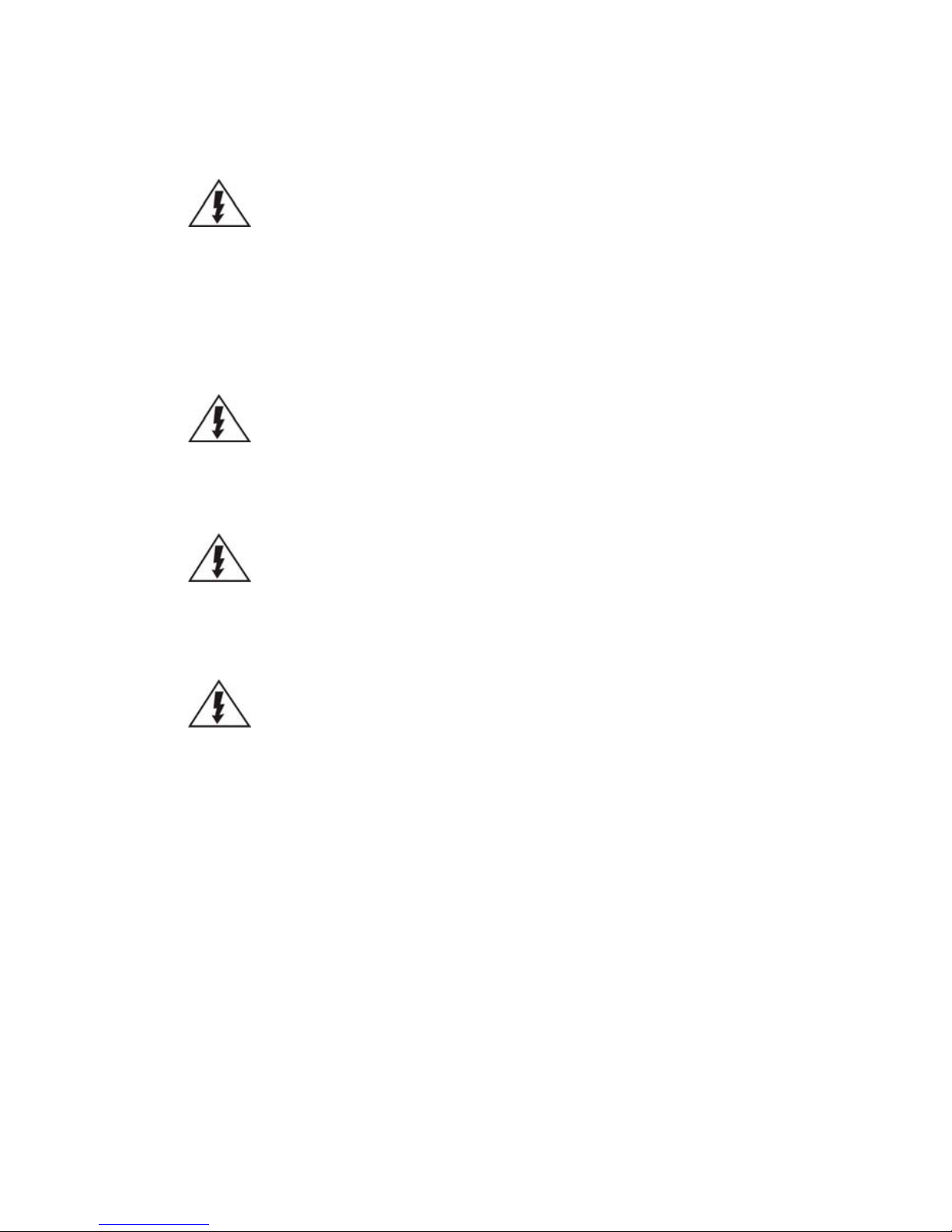
2.1. Front Panel
SMR2000 Series
SMR5000 Series
SMR Pro
SMR P ro
SMR6000H/
8000 Series
SMR4000U/
8000U Series
SMR P ro
33335 33334 33336
Function
1. LCD Display
Shows system messages.
2. Enter Switch
Confirms the options and functions after the Select Switch is used.
3. Select Switch
Shows the menu for choosing RAID0, RAID1 or RAID5. Please refer to the
RAID Option Table while choosing a RAID level.
4. LED Indicators
Indicates the network, hard drive, and system status.
5. Power Switch
Powers up the SMR. When the power is on, the power indicator will
shine in blue.
6. Front USB Connector
Connects external accessories such as mouse, keyboard or other
external devices.
7. Video Back Up Button
Reserved.
8. Hard Drives Slots
Hard drive locations
Page 26
26
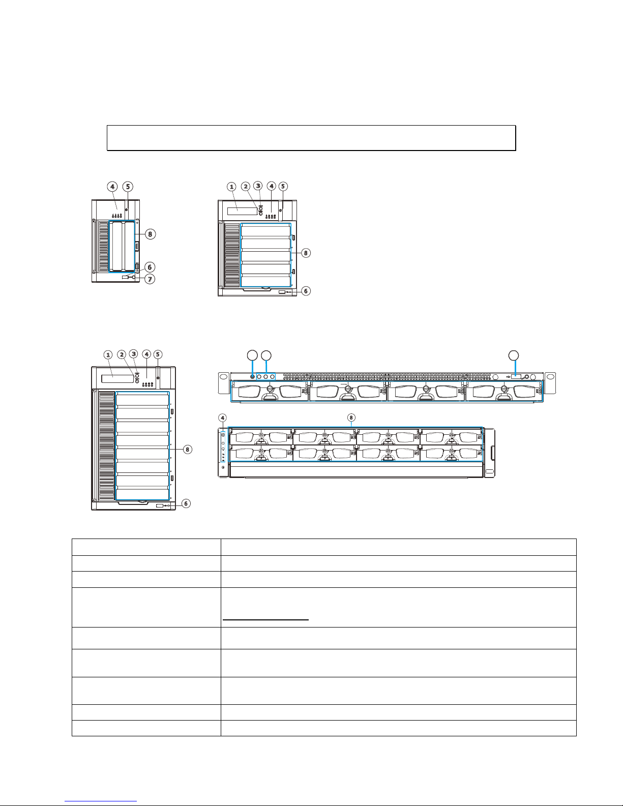
2.2. Rear Panel
SMR2000 Series
SMR5000 Series
1
2
EonNAS
1
2
SMR6000H/
8000 Series
SMR4000U/
8000U Series
3
4
1
5
6
9
10
11
12
13
8
16
3333633335 33334 33333 333323333
11
33331
33335
3333
11 33334
6
33331
33333
14
9
3333
10
3333
13
15
Function
1. Power Socket
Used for connecting power cable.
2. e-SATA Port x1
Used for connecting the SMR with e-SATA drives.
3. USB Port x4
Used for exporting video clips as evidence support to external storage devices.
4. LAN Port (GbE Ethernet
port) x2
Used for connecting the SMR with the network. Note that only the upper LAN
port can be used.
5. Restore Button
Use for reset the system to factory default. For details, please refer to the table
below.
6. VGA Port
Used for attaching an external monitor to the SMR.
7. 12V DC Power Port
Used for connecting power cable.
8. Kensington Lock-hole
For use with a Kensington lock. Please refer to your Kensington lock for
instructions.
9. COM Port
Reserved
10. HDMI Port
Used for connecting audio/video devices such as video projectors and DVD
players.
Page 27

27
11. USB Port x2
Used for exporting video clips as evidence support to external storage devices.
12. Safety Switch
Used for preventing injury if someone inadvertently attempts to open the
machine. Please make
sure it’s on after the power cable is attached to the power socket.
13. Audio Ports
Used for attaching audio devices such as headphones and speakers.
14. Power Supply Units
The two power supplies are hot-swappable and redundant.
15. Power Switch
The power switch on 8000U system can be located on the rear panel.
16. BNC Connector
Used for connecting analog cameras.
Page 28
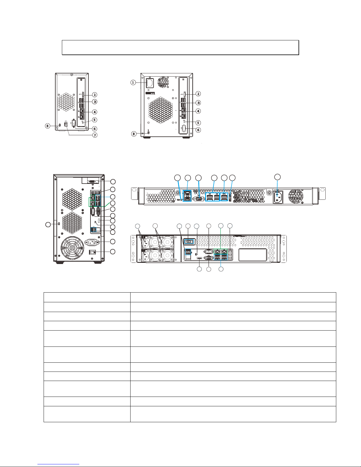
28
2.3. Hard Drive Designation
The hard drive arrangement for each system is shown below. The general
alignment is from left to right and/ or top to bottom in numeric order.
SMR2000 Series
SMR5000 Series
SMR6000H Series
SMR8000 Series
SMR4000U Series
SMR8000U Series
Page 29
29
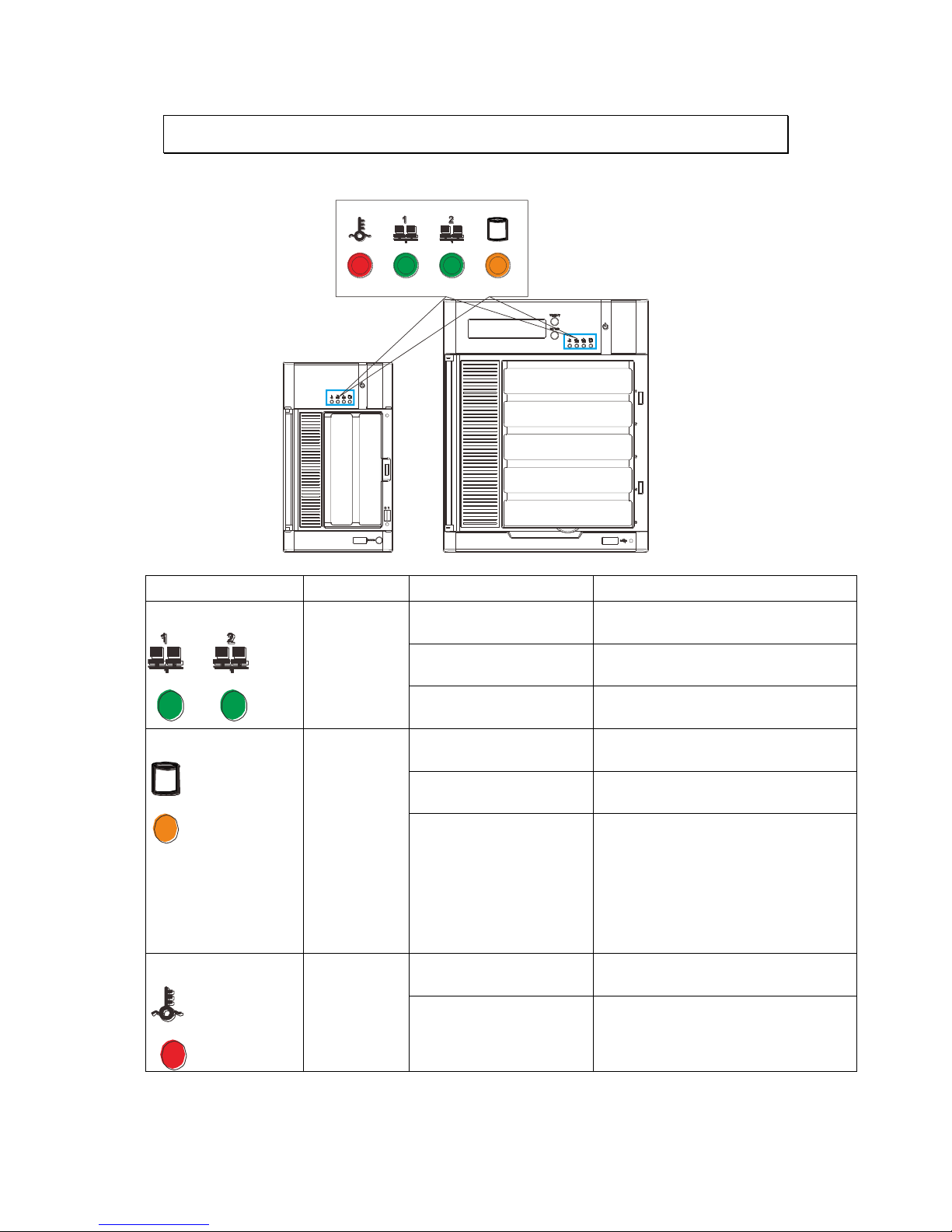
2.4. LED Definitions
2.4.1. Desktop System Front Panel LEDs
Name
Color
LED Status
Function
Network
Green
On
Indicates that power is on and
network is connected.
Indicates that network is
disconnected.
Indicates that network activity
is in progress.
HDD
Amber
On
Indicates that the hard drive can
be accessed.
Indicates that a hard drive
read/write error occurred.
Indicates one of the followings:
(1)Disk volume creation is in
progress.
(2)Online RAID level migration is
in progress.
(3)RAID rebuilding is in progress.
System
Red
On
Indicates the system fan is
malfunctioning.
Blink
Indicates that system is starting
up.
Page 30
30
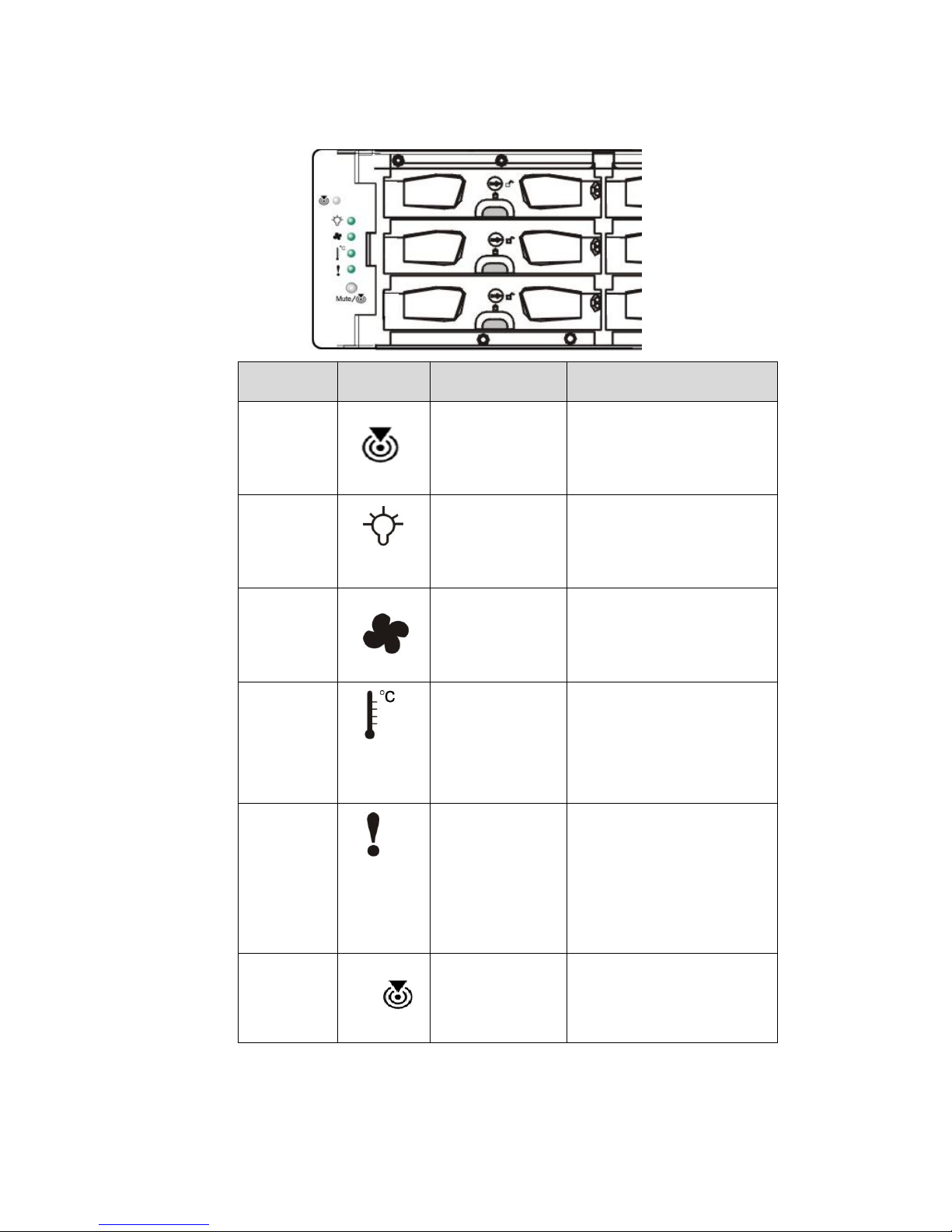
2.4.2. Rackmount System Front LED Panel
LEDs / Button
Icon
Color
Description
Service LED
White
This LED indicates the
system requires service
when lit.
Power Status
LED
Green
(Normal) /
Amber (Fail)
This LED is used to warn
users of power supply
status
Cooling
Module
Status LED
Green
(Normal) /
Amber (Fail)
This LED is used to warn
users of cooling module
status
Temperature
Sensor
Status LED
Green
(Normal) /
Amber
(Abnormal)
This LED is used to warn
users of temperature
status
System Fault
LED
Green
(operating
normally) /
Amber
(Warning)
This LED indicates
normal operation /
system failure
Mute and
Service LED
Off Button
Mute/
Reserved
Page 31

31
2.4.3. Drive Tray LED
Two LED indicators are located on the right side of each drive tray. When
notified by a drive failure message, you should check the drive tray indicators to
find the correct location of the failed drive.
1
2
Name
Color
LED Status
Function
1. Drive Busy LED
Blue
Blink
Indicates that the data is being
written to or read from the
drive.
Off
Indicates that there is no
activity on the disk drive.
2. Power Status LED
Green / Red
On
GREEN indicates that the drive
bay is populated and is working
normally.
RED indicates that the disk drive
has failed, or a connection
problem occurred.
Page 32

32
2.4.4. Rear Panel Ethernet LED
SMR2000 Series
SMR5000 Series
1
2
EonNAS
1
2
SMR6000H/
8000 Series
SMR8000U Series
1
2
RS 232/485
1
2
Name
Color
LED Status
Function
1. Link Status LED
Green
On
Indicates that the connection is
established.
Off
Indicates that the connection is
not established.
2. Activity LED
Amber
Blink
Indicates data transfer activity
Page 33

33
Chapter 3. Software Overview
3.1. Software Introduction
Video Management Software (VMS) is a highly modular and powerful video and
hardware management suite that incorporates Server recording, management, and
video monitoring and playback functionalities to serve the core purposes of a video
surveillance system.
It operates in a client-server mode: The Local Client and Local Domain Server run
for standalone SMR/NVR/VMS Server, while the Remote Client receives live video
streams and event video playbacks from LAN or Internet. All administrative tasks
are performed on the Client. The client software provides the ability to monitoring
and playback recorded videos from multiple cameras. And for users having multiple
SMR/NVR/VMS Servers, Central Management Software (its main functions are the
same with the VMS) can be utilized to manage over the domain infrastructure.
Page 34

34
3.2. Module Framework
VMS/NVR Server
Combines video recording, archival and retrieval functionalities for
individual servers/standalone PCs.
Serves as the connection point for client stations.
Local Domain Server
The interface between the VMS/VI Servers and any clients.
User authentication server.
Local Client
Local access, VMS Client installed on standalone PCs/SMRs for live
video monitoring, event recording playback access and VMS system
configuration.
Remote Client (full functions)
Remote access, VMS Client installed on remote PCs for live video
monitoring, event recording playback access.
Serves as the default configuration point for NVR2000 series, which do
not have a Local Client.
Web Client (for simple use)
Remote access, an ActiveX application (OCX) installed on remote PCs
for live viewing and event playbacks through the web browser.
SPhone Client (for simple use)
SPhone Client installed on iOS/ Android devices for basic live viewing.
Web Server
Allows user to access the live video stream, PTZ control and event
recording playbacks through Microsoft Internet Explorer 7.0 (or higher)
after the Web Clients components are downloaded.
VI Server
The video intelligence processing point for a VMS solution.
Preinstalled on SMR/NVR Server, and optional on a separate server/PC
(VMS).
SCC Domain Server
Allows centralized control over multiple Trusted VMS Server points and
connections from multiple clients.
SCC Client
Page 35

35
Software capable of accessing multiple Trusted VMS Servers through
the SCC Domain Server
Page 36

36
3.3. System Architecture
VMS operates in scalable client - server architecture. This architecture can be
divided into three types: (1) Standalone Server (2) Standalone Server + Remote
Client (Web Client/SPhone Client) (3) Multiple Servers + SCC Client.
These are the hardware requirements for using PCs as Server or Client.
VMS Server + Client
Support NVRs
≥ 32CH
16~32CH
≤ 16CH
OS
64-bit :
Windows 7 Professional, Enterprise, Ultimate
CPU
Intel Core i7‐980X or
above
Intel Core i7‐860
or above
Intel Core i5‐650
or above
Memory
4 GB or above
Display
nVidia GeForce GTX660 2GB or above
Hard Drive
SATA 7200 RPM, 500 GB or above
Network
1 Gbps or above
Remote Client
OS
64-bit :
Windows 7 Professional, Enterprise, Ultimate
CPU
Intel Core i7‐980X
or above
Intel Core i7‐860
or above
Intel Core i5‐650
or above
Memory
4 GB or above
Display
nVidia GeForce GTX660 2GB or above
Hard Drive
SATA 7200 RPM, 500 GB or above
Network
1 Gbps or above
VMS Server Only
OS
64-bit :
Windows 7 Professional, Enterprise, Ultimate
CPU
Intel Core i3‐530 or above
Memory
4 GB or above
Display
On board (generic) 256MB or above
Hard Drive
SATA 7200 RPM, 500 GB or above
Network
1 Gbps or above
Page 37

37
3.3.1. Standalone Server (Client-Server All-in-One)
For users with standalone Server, the Local Client UI is used to manage SMR
Server services:
※Application:
The Server, IP cameras are all in the same LAN.
Use SMR as Server
No installation needed.
Use PC as Server
Install both the VMS/NVR Server and VMS Client on a PC:
Insert the VMS/IPCAM product CD. Click VMS Suite on the menu to start the
installation. Choose Typical Setup. If you don’t need video analytic functions,
Advanced Setup can be selected to uncheck the VI Server.
Page 38

38
3.3.2. Standalone Server + Remote Client (Web
Client/SPhone Client)
For remote users to connect to SMR/NVR Server, a remote access, VMS Client
installed on remote PCs is needed for live video monitoring, event recording
playback access.
Also, the Web Client, an ActiveX application (OCX) can be used for basic live
viewing and event playbacks through the web browser, while SPhone Client can
be used for basic live viewing on iPhone/Android devices.
Page 39

39
Application1: Internet
The Server, IP cameras and the PC/iPhones are all in the same LAN.
[NVR Server]
Use SMR/NVR as Server
No installation needed.
Use PC as Server
Install the VMS/NVR Server on a PC:
Insert the VMS/IPCAM product CD.
Click VMS Suite on the menu to start the installation.
Choose Advanced Setup to uncheck the VMS Client.
If you don’t need video analytic functions, the VI Server can also be unchecked.
Install the Web Server on the PC:
Insert the VMS/IPCAM product CD.
Click Browse CD/DVD in the menu.
Double click WebServerSetup.exe to start the installation.
[Client]
Install the VMS Client on PCs:
Insert the NVR/SMR product CD.
Click VMS Client on the menu to start the installation.
Install the Web Client on the PCs (Optional):
Page 40

40
Launch Microsoft Internet Explorer 7.0 (or above) and enter your VMS Server IP
address + “/webclient” in your web browser’s URL location, eg.
http://172.18.6.9/webclient to download the Web Client application.
Install the Web Client on the PCs (Optional):
Install the SPhone Client (Optional):
Download the SPhone Client from App Store on the iPhone desktop.
Install the SPhone Client (Optional)
Download the SPhone Client from App Store on the Andriod phone desktop.
Note: Please refer to Installing the VMS and Installing the Web Client for details.
Page 41

41
Application 2: Internet
The Server, some of the IP cameras and the PC are all in the same LAN, while
the other IP cameras are installed in remote location with Public IP.
3.3.3. Multiple Servers + SCC Client
For users with multiple SMR/NVR Servers, SCC Client UI is used to manage over
the domain infrastructure.
Page 42

42
Application3: Internet
(1) The Servers, IP cameras and the PCs are in LAN A.
(2) Some IP cameras are installed in LAN B, which is behind a different router in a
remote location.
(3) Users are allowed to connect the SMRs/NVRs from remote PC over the Internet.
CMS Client
NVR
Server
VI Server
CMS Domain Server
CMS Client
Multiple Servers + CMS Client
NVR
Server
NVR
Server
[NVR Server]
Use SMR/NVR as Server
No installation needed.
Use PC as Server
Install the VMS/NVR Servers on PCs:
Insert the VMS/IPCAM product CD.
Click VMS Suite on the menu to start the installation.
Choose Advanced Setup to uncheck the VMS Client.
The VI Server can also be unchecked, if you don’t need video analytic functions.
[VI Server] (Optional)
You can choose to install the VI Server only on a standalone PC to manage the
video intelligence data.
Insert the VMS/IPCAM product CD.
Click VMS Suite on the menu to start the installation.
Choose Advanced Setup to choose VI Server only.
Page 43

43
[SCC Domain Server]
Install the SCC Domain Server on a PC:
Insert the NVR/SMR product CD.
Click SCC Suite on the menu to start the installation.
Choose Advanced Setup to select the SCC Domain Server only.
[SCC Client]
Install the SCC Client on PCs:
Insert the NVR/SMR product CD.
Click SCC Suite on the menu to start the installation.
Choose Advanced Setup to select the SCC Client only.
Note: (1) For users don’t have Surevon SMR/NVR series, please contact your
dealer for the SCC installation file. (2) The SCC Domain Server can also
be installed together with the SCC Client in the same PC by choosing
Typical Setup. (3) Please refer to Installing the VMS and Installing the
SCC for details.
Page 44

44
3.3.4. Network Requirements
In order to preserve enough bandwidth for surveillance video, a surveillance
network is presumed to be free of user/business traffic. Server software
currently supports Class B and Class C type addresses. Currently the Server
software only searches for Servers on the same subnet. Cameras should also
reside on the same subnet.
Opening Ports
If access through a firewall in a local network is required, try opening the
following ports: SMTP (25), HTTP (80), FTP (20, 21), OMNI (2809), HTTPS (443) and
RTSP (554, 8554.). Other ports should also be opened while using port forwarding
to access the VMS Server: Stream Port (9090), Doman Data Port (9060), Log
Download Message Port (15507) and Log Download Data Port (9080).
Note: Please refer to Port Forwarding Section for more details.
Warnings / Precautions
If the Server and a VMS client reside on separate subnets, please set up gateway,
VLAN, or cross-subnet routing to bridge surveillance traffic. Please consult with
a network administrator for problems with network setups. A VMS client needs
to be rebooted when network settings are changed.
Page 45

45
3.4. Port Forwarding
Port forwarding is a name given to the combined technique of:
1. Translating the address and/or port number of a packet to a new
destination.
2. Possibly accepting such packet(s) in a packet filter (firewall).
3. Forwarding the packet according to the routing table.
To illustrate its concept, two computers on the Internet that communicate with
each other using TCP/IP or UDP/IP protocols(though the process is not limited to
these) utilize ports to identify the opposite connection points of each other where
the data packets supposed to go to. In order to communicate, each computer
knows the port of another computer (in addition to IP address) and sends the data
to that port. Port forwarding forwards these ports in such a way that when one
computer sends data to the specific port of another computer, the data is actually
sent to a different port. This allows remote computers to connect to a specific
computer or service within a private LAN.
In a typical residential network, nodes obtain Internet access through a DSL or
cable modem connected to a router or network address translator (NAT/NAPT).
Hosts on the private network are connected to an Ethernet switch or communicate
via a wireless LAN. The NAT device's external interface is configured with a public
IP address. The computers behind the router, on the other hand, are invisible to
hosts on the Internet as they each communicate only with a private IP address.
When configuring port forwarding, the network administrator sets aside one port
number on the gateway for the exclusive use of communicating with a service in
the private network, located on a specific host. External hosts must know this port
number and the address of the gateway to communicate with the network-internal
service.
When used on gateway devices, a port forward may be implemented with a single
rule to translate the destination address and port. The source address and port are,
in this case, left unchanged. When used on machines that are not the default
gateway of the network, the source address must be changed to be the address of
the translating machine, or packets will bypass the translator and the connection
will fail.
Page 46

46
3.4.1. Port Forwarding for Accessing VMS Server
To enable port forwarding for accessing VMS Server, please follow the steps below:
1. Do Router Port Mapping for VMS/NVR Server
Go to Setup > Other Tasks > Server > Router Port Mapping in VMS after it is
installed.
Note: The VMS/NVR Server is preinstalled in NVR2000/SMR Series.
A Router Port Mapping window will prompt for entering port numbers. Please put
in the numbers as listed below:
Stream Port: 9090
Login: Port: 2809
Doman Data Port: 9060
Log Download Message Port: 15507
Log Download Data Port: 9080
Page 47

47
2. Open Ports on the Router
Host Ports: The private ports that the internal VMS/NVR Server use, which are
unchangeable.
Global Ports: The public ports for remote clients to connect to the internal
VMS/NVR Server. The Global ports are changeable, but the simplest way is to
make them the same with the host ports.
Please open the listed ports on your router:
Port(Host/Global Port)
Protocol
Port Number
Domain Message Port
UDP
9050
Domain Data Port
TCP
9060
Login Port
TCP
2809
Stream Port
TCP
9090
Log Download Message Port
TCP
15507
Log Download Data Port
TCP
9080
Page 48

48
Note: Camera port (default: 80) and stream port (default: 6002) for accessing
cameras should be opened while VMS/NVR Server and the cameras and are
not in the same LAN.
Page 49

49
Chapter 4. Installation
4.1. Before You Start
4.1.1. Checklist for Operating Environment
Users need to prepare the following devices to set up the surveillance system.
Network Video Recorder
SMR series
IP Camera
Network Cameras (such as CAM2320)
Network
Existing LAN, Switch, Router or Hub (please see the
Network Topology below)
Storage
Hard Drives
Note: The hard drives should be purchased separately.
4.1.2. Checklist for Network Topology
Make sure you have the right switch/hub for your environment. Either of the
following options will work.
Common Topology
Reference Product
Existing LAN
LAN Switch with DHCP Server
Office LAN
Router
LAN Switch with build-in DHCP Server
D-Link DIR-130
Switch/Hub
No DHCP Server(refer to the Note below)
D-Link DES-1108
Note: For devices without DHCP Server function, please refer to Configuring
DHCP Service Section.
Page 50

50
4.2. Hard Drive Installation
4.2.1. Hard Drive Installation Prerequisites
Purchase hard drives having the same capacity and using same interface with
the pre-installed ones.
4.2.2. Inserting Hard Drive into Drive Tray (Desktop
Series)
1. Open the front panel of the SMR system.
2. Press the release button (indicated by the blue arrow) on the bezel, the
bezel panel should open automatically and gently pull out the hard drive
tray.
Release button
3. Place the hard drive into the drive tray. Make sure the hard drive’s
interface connector is facing the open side of the drive tray and its label
side facing up. Adjust the drive’s location until the mounting holes in
the drive tray are aligned with those on the hard drive. Secure the drive
with four supplied flat head screws.
Page 51

51
4. With the tray bezel open, insert the hard drive and tray into the system
enclosure.
5. Close the tray bezel.
6. Use the small flat blade screwdriver to turn the bezel lock from the
unlock to lock position.
7. Repeat above steps to install other hard drives.
8. Close the system front panel when you are done installing hard drives.
Page 52

52
4.2.3. Inserting Hard Drive into Drive Tray (Rackmount
Series)
1. Remove the tray from the enclosure, press the release button and
gently pull out the tray.
2. Place the hard drive into the drive tray. Make sure the hard drive's
interface connector is facing the open side of the drive tray and its label
side facing up. Align the drive and the mounting holes on the tray.
3. With the tray bezel open, insert the installed hard drive and tray into
the enclosure. Once inserted, close the tray bezel.
Page 53

53
4. Use a small flathead screwdriver to rotate the tray bezel lock from the
unlock position to the lock position.
Page 54

54
4.3. System Connections
IP Encoder
Analog Camera(s)
IP Camera(s)
Monitor
SELECT
ENTER
SMR
Et herne t Con n ect ion
US B C onn e ctio n
Vi deo/Mon i t or Co nnec tion
Note: Shaded areas are optional devices.
Connect cables to the rear panel ports as follows:
SMR2000 Series
SMR5000 Series
1
2
EonNAS
1
2
SMR6000H/
8000 Series
SMR8000U Series
1
2
RS 232/485
Page 55

55
Insert mouse, keyboard or other external devices to the USB port (blue
rectangles) for operating the Video Management Software (VMS).
Insert the LAN cable to the upper LAN port (blue circles) to connect
the SMR to a local network where your IP cameras reside.
(Connection to analog cameras is also available via an IP encoder.)
Connect an external monitor capable of 32bit or higher color quality to
the VGA Port (red rectangles) to view the VMS interface.
Page 56

56
4.4. Powering up SMR
4.4.1. SMR Desktop Systems
1. Attach the power cable to the power socket on the rear panel.
2. (SMR6000H/8000 Series) Make sure the safety switch on the rear panel is
switched to the “-” side, which means that it is turned on.
3. Press the Power Switch.
4. See if the System LED is blinking, which means the system is
starting up.
5. See if the Network LED has turned green, which indicates power is
on and network is connected.
6. See if the HDD LED is on, which means the hard drive can be
accessed.
7. (SMR5000/6000H/8000 series) The Server name and the IP address will be
shown on the LCD screen.
SELECT
ENTER
Server
172.18.6.179
4.4.2. SMR Rackmount Systems
1. Press the Power Switch and a beep sound should follow.
2. When powered on, the service LED should remain off
while the rest of the status LEDs on the front panel
should light up green to indicate normal operation.
Service LED: Off
Power LED: Green
Cooling fan LED: Green
Thermal LED: Green
System fault LED: Green
Page 57

57
4.5. Install Wizard
When you run the SMR series for the first time, you need to go through the
following steps within the Quick Install Wizard after logging in.
1. Make sure the hard drives are inserted into the SMR case. Click Next
to continue.
Page 58

58
2. Click Storage Manager to do RAID configuration.
Click Setting, choose the RAID level in the Advanced Settings dialogue, and
then click Create Logical Drive to create the RAID configuration.
WARNING
All hard disk data will be erased.
Page 59

59
These are the RAID options for SMR models.
Minimum Hard Drives
RAID Options
Descriptions
2
RAID0
Provides no protection, but offers maximum capacity.
2
RAID1
Provides best protection. Your data will be mirrored.
3
RAID5
Provides protection against one drive failure.
Please click OK after the configuration is done, and the system will
reboot automatically. About 2 minutes later, the Wizard window will
appear again. Click Next to continue.
3. System initialization will start.
The system will shut down after the initialization is done successfully.
Please click OK.
Press the power switch to restart the system. About 1.5 minutes later,
the Wizard window will pop up again.
4. The recommended monitor resolution for the SMR is 1280x1024. Click
Open Resolution Tool to change the resolution setting.
Choose Single Display as the operating mode and Monitor as the
display selection in Primary Device. Change the screen resolution in
Display Settings. Click OK to finish.
Page 60

60
Note: SMR8000 series support dual monitor display.
Click Next to continue.
5. The default password for SMR login is admin. If you want to change the
password, please enter a new one in both the blanks of New Password
and Confirm.
Page 61

61
If you want to keep using the default password, please tick Use old
password.
Click Next to continue.
6. Choose the time zone and set the actual date and time for the SMR
system.
Click Next to continue.
7. Set an IP address for the SMR Server. Obtaining the IP address from DHCP is
recommended.
Page 62

62
The IP will change after the system is restarted.
Click Next to continue.
8. Click Scan for Cameras to add cameras to the SMR server.
The cameras that can be added to the Server will be displayed.
To add a camera to the system, check the box by the camera entry. You
may also check the Select All box at the bottom of the window to select
all the cameras found.
Page 63

63
Enter the username and password, and press Apply Selected. Click OK
to add the selected cameras to the Server.
8. Click Finish to end the wizard.
9. The VMS will start automatically after the wizard is finished.
Page 64

64
4.6. Software Installation
4.6.1. Installing the VMS
Note: For NVR2000/SMR series, users have to install VMS Client on remote PC(s)
when distant live viewing and playback are needed.
1. Insert the VMS/IPCAM CD-ROM. The CD should autorun. If it does not,
open the CD manually and double-click autorun.exe. The menu below
will be displayed.
Click VMS Suite to start the installation.
Page 65

65
2. Choose a setup type from Typical and Advanced. Then Click Next when
you are satisfied with your selection.
3. You may choose to install among the following while Advanced
Setup Type is selected:
VMS Server Suite – Includes the VMS Server and Local Domain
Server, VI Server and VMS Client.
VI Server
VMS Client
Web Server
Page 66

66
4. The confirmation screen will display. Click Install. A progress bar will
display, indicating installation progress.
Page 67

67
5. When installation is finished, an informational screen will display.
Click Finish to complete installation.
Page 68

68
6. The system will prompt for a restart. A restart is required before the
VMS will function correctly. You may choose to immediately
automatically restart your computer, or restart your computer later.
Clicking Finish will apply your choice.
Page 69

69
4.7. Starting the VMS Client
To start the software, click Programs > VMS Suite > VMS Client under the
Windows Start menu.
The software will prompt for the following information:
Access Method – Directly Access or Internet Port Forward.
Type – Choose VMS.
Server – The IP address for the VMS/NVR Server. You can click Search
button to obtain it. For users of port forwarding, it should be the IP
address of the router.
Port – The Login Port for port forwarding - 9050. It should be set
under Server > Other Tasks > Port Mapping after the first login.
Note: (1) Please refer to Port Forwarding Section for more details. (2) SCC does
not support port forwarding functionalities.
Username – The username for the domain, which is always admin.
Password – The password for the domain. Default password is admin.
Click Login after the password (and port number) is entered.
Page 70

70
4.7.1. Checking the Software Version
Users can see the software version at the lower right corner of the window after
logging in.
4.7.2. Logging out
The Client can be logged out of all the Servers configured on the system by
pressing the Logout button on the upper right hand corner in the GUI. Logging
out of individual servers can be achieved by double clicking the server entry and
clicking the Yes button on the confirmation screen.
Closing the window using the X button on the top right corner will exit the
Client. A confirmation screen will appear, click Yes to exit the system.
Note: (1) If the system becomes unresponsive, users can force shutdown the
system (press and hold the power until the system shuts down). This should
only be done when the system is unresponsive!
Page 71

71
Chapter 5. Reinstallation
5.1. Reset RAID
The actions of reset RAID (to change the RAID type or clear video data in the
RAID) and reset the whole system (to reinstall the OS) would require a
reinstallation on your SMR.
Note: (1) RAID from other vendors is not compatible.
(2) Make sure the deploying disks are NON-RAID and unformatted before
reinstallation.
(3) Reinstallation functionality is for SMR2000/4000U/5000/6000H only.
(4) SMR8000 and NRV21000 do not support OS reinstallation.
Steps to rest RAID:
1. Press “Ctrl + l” to enter the RAID bios to boot up SMR.
Note: RAID bios window will appear after pressing “Ctrl + l”.
2. Select “3. Reset Disk to NON-RAID” and then press “Enter”.
Page 72

72
3. Use the space bar on your keyboard to select the hard disk drives you’d like
to reset.
4. Once selected, press “Enter” and type “Y” to confirm and reset the selected
hard disk drive to NON-RAID.
Page 73

73
Once the reset is done, the hard disk drive will appear as NON-RAID Disk.
5. Press “ESC” to exit and then turn the SMR off to activate the settings.
Page 74

74
5.2. Reset the Whole System
1. Before power on the SMR, please take out the existing hard disk drive to
trigger system starts from DOM.
2. Switch on your SMR and you will see the “System started from DOM”.
Click “OK” to login.
3. Login VMS.
4. You will see a popup dialog asking you to configure the video path. Click
“No”. You will see the following image.
Page 75

75
5. After that, you will see the Install Wizard as the image shown below. If
the install Wizard does not run automatically, click F4 to launch.
6. Insert an unformatted hard disk drive into the SMR and click “Next”
button. If the hard disk that requires a reset is already in your SMR, click
“Next” button to proceed.
7. Skip “Step2: Storage Manager” if you want to keep your old videos and
RAID system.
Select the “Step2: Storage Manager” to set RAID configuration and go to
the “Step 3: Initialize the System”.
Page 76

76
8. Click Setting, choose the RAID level in the Advanced Settings dialogue,
and then click Create Logical Drive to create the RAID configuration.
WARNING
All hard disk data will be erased after this step.
These are the RAID level options for SMR models.
Minimum Hard Drives
RAID Options
Descriptions
2
RAID0
Provides no protection, but offers maximum capacity.
2
RAID1
Provides best protection. Your data will be mirrored.
3
RAID5
Provides protection against one drive failure.
9. After the configuration is done, click OK, and the system will reboot
automatically.
10. About 2 minutes later, the Install Wizard will appear again. Click Next to
continue.
11. In the “Step 3: Initialize the System”, after restart, login to your SMR
and the system initialization will start.
Page 77

77
12. After the initialization is done, the system will ask you to shutdown the
SMR. Click OK and turn the power off and on manually. The Install
Wizard will appear again after power on.
13. Press the power switch to restart the system. About 1.5 minutes later,
the Install Wizard will appear again.
14. In the “Step4: Display Resolution”, the recommended monitor resolution
for the SMR is 1280x1024. Click Open Resolution Tool to change the
resolution setting. If the resolution does not require a change, click
“Next” and skip the “Step4: Display Resolution”.
15. Select Single Display as the operating mode and Monitor as the display
selection in Primary Device. Change the screen resolution in Display
Settings. Click OK to finish.
Note: SMR8000 series support dual monitor display.
Page 78

78
16. Click Next to continue.
17. In the “Step 5: Change Password”, If you want to change the password,
please enter a new set in the blanks of New Password and Confirm. If
you want to use the old password, just check on the option “Use Old
Password”. Click Next to continue.
18. In the “Step 6: Time Settings”, select the time zone and set the actual
date and time the same as your region’s time and date. If the date and
time are incorrectly set, the functionality of VI, playback and schedule
may not work properly. Click Next to continue.
Page 79

79
19. In the “Step 7: Network Settings”, set the IP address for the SMR server.
It is recommended to Obtain the IP Address From DHCP. Click Next to
continue.
20. In the “Step 8: Scan for Cameras”, add cameras to the SMR server.
21. The available cameras will be listed. Check the box of the cameras that
you’d like to add in the SMR. Check the “Select/Delete All” box to add
all the available cameras in.
22. Type the username, password and click “Apply Selected”.
23. Click OK to confirm and save the settings.
24. Click Finish to end the Install Wizard.
25. The VMS will start automatically after the Install Wizard is close.
Page 80

80
26. If your SMR version is above 2.4.8A02 and you have changed SMR RAID
type, press F7 to reinitialize the updated RAID status on DOM (Internal
SSD). Click Yes to clear old Storage Configurations.
27. Click Yes to restart the SMR to activate the settings.
28. Turn on the SMR to have it start working.
Page 81

81
Chapter 6. Basic System Settings
6.1. Storage Management
1. To access the information about the drives configured in your Server,
highlight and click the Storage Manager option under Server Settings.
2. All available Logical Drives, as well as their sizes, free space, and status will
appear.
Click Edit to set the log and location for saving the video recordings.
(Step 3 and 4 are for the remote client of NVR2000/SMR Series.)
Page 82

82
3. Click the target drive first and then Settings.
In “Advanced Settings” dialogue, “General” tab, click Check.
4. Choose the RAID level, and then click Create Logical Drive to create the
RAID configuration.
Note: Storage Manager can also be accessed by clicking Server > General Tasks
> Storage or Server Entry > Common Tasks > Common Server Tasks >
Storage in the VMS Console.
Page 83

83
6.2. Adding Cameras to the Server
Cameras can be added to the Server in two ways: via an automatic scan or by
manually inputting the camera information.
6.2.1. Automatic Scan for Cameras
To begin an automatic scan for cameras:
1. Right-click the Server entry and select Scan for Cameras. The system will
respond by beginning an automatic scan. Once the scan is complete,
the cameras that can be added to the Server will be displayed.
Information available for each camera will include:
Name – The default camera name (Make/Model)
Status – The camera will display New if it has not been added to
this Server, otherwise it will display Assigned.
IP Address
MAC Address
Vendor - Including ACTI, ASONI, AVTECH, AXIS, Arecont, Sosch,
Brickcom, DyNACOLOR, D_Link, Dahua, EDIMAXHIKVISION,
EverFocus, HIKVISION, IQinVision, Lilin, Eessoa, Mobotix,
ONVIF, Panasonic, SIMON, SONY, Samsung, Surveon, VIVOTEK,
and General.
Model
Page 84

84
2. To add a camera to the system, check the box by the camera entry. You
may also check the Select All box at the bottom of the window to select
all the cameras found.
Enter the username and password, and press Apply Selected. Click OK
to add the selected cameras to the Server.
The following windows will prompt for validation.
Page 85

85
3. (Optionally) Double-click any camera entry to bring up the camera detail
page. From this page you may change the following information:
IP Address – Changing this value will affect connectivity.
Camera Port – The web access port, default is 80.
Stream Port – Default is 6002.
Vendor – Changing this value will affect connectivity.
Model – Changing this value will affect connectivity.
User Name – This value is not always required.
Password – This value is not always required.
Camera Name – It is recommended you change this value if you
have more than one camera of this make/model.
Camera Description
Camera Icon – You can also import your own icon by clicking on
the Browse button and choosing an icon file. Valid icon files
include JPEG, GIF, PNG, BMP and ICON files.
Finally, you can access the web interface for the camera by clicking on
the Go to Web Interface button. Click OK to save your changes, or
Cancel to exit without saving.
4. (Optionally) You may access the IP Utility for camera configurations of
by clicking the IP Camera Utility button.
5. Click OK to add the selected cameras to the Server.
Page 86

86
Note: Automatic Scan for Cameras can also be accessed by clicking Camera List
> General Tasks > Scan for Cameras or Server Entry > Common Tasks
> Common Server Tasks > Scan for Cameras in the VMS Console.
Page 87

87
6.2.2. Manually Adding Cameras
To manually add a camera to the Server:
1. Right-click the Server entry and select Add Camera.
2. In the camera window fill out the following information:
IP Address
Camera Port – This value will automatically populate with the
default value for the Vendor and Model selected.
Vendor - Including ACTI, ASONI, AVTECH, AXIS, Arecont, Sosch,
Brickcom, DyNACOLOR, D_Link, Dahua, EDIMAXHIKVISION,
EverFocus, HIKVISION, IQinVision, Lilin, Eessoa, Mobotix,
ONVIF, Panasonic, SIMON, SONY, Samsung, Surveon, VIVOTEK,
and General.
Model - when “General” is selected, “RTP over TCP” and “RTP
over UDP” can be further defined.
Stream Port – This value will automatically populate with the
default value for the Vendor and Model selected.
Page 88

88
User Name – This value is not always required.
Password – This value is not always required.
Camera Name – It is recommended you change this value if you
have more than one camera of this make/model.
Camera Description
URI for Stream: when “General” is selected, “URI for Stream
1” can be further defined.
For example:
For a Surveon IP camera, type
RTSP://<IP of the IP camera>/stream1 or stream2
For an AXIS IP camera, type
RTSP://<IP of the IP camera>/<codec>/media.amp
For a HIKVISION IP camera, type
RTSP://username:password@<IP of the IP Camera>
Camera Icon – You can also import your own icon by clicking on
the Browse button and choosing an icon file. Valid icon files
include JPEG, GIF, PNG, BMP and ICON files.
3. Finally, once basic camera information is filled in, you may access the
web interface for the camera by clicking on the Go to Web Interface
button. Click OK to add the camera.
Note: Cameras can also be added manually by clicking Camera List > General
Tasks > Add Camera in the VMS Console.
Page 89

89
6.3. Setting Recording Schedule
A global Schedule applies to all cameras, while individual schedules are for
each camera. Individual schedules take precedence over global schedules.
6.3.1. Weekly Scheduling
1. Right-Click the VMS entry and choose Schedule Manager > Global
Settings or Individual Schedule to bring up the Weekly Schedule popup.
2. If setting individual schedule and more than one camera is configured,
choose the camera you wish to set from the list.
3. The schedule grid corresponds to every hour in the week. Click on one
of the four recording methods and then click on the grid area to “paint
in” the method for the corresponding hour.
4. Click the Apply button to apply the schedule and OK to exit the dialog.
Page 90

90
5. (Optional) You may go to the VI setting panel by clicking Go to VI
Settings.
Page 91

91
6.3.2. Daily Scheduling
1. Right Click the server entry and choose Add Daily Schedule.
2. Click the Select Date selection box and choose the date that you want
to schedule.
3. Click on one of the methods and then click on the grid area to “paint in”
the method for the corresponding hour.
4. Click OK to apply the changes.
Page 92

92
6.4. Adding Alarm Rules
Alarm rules can be created using the following elements:
Rule: A short description. For example, “east–fence intrusion detection”
or “front entrance access control.”
Condition: Specifies triggering conditions such as Motion/Video
loss/Sensor input/Clock Alarm, etc.
Action: Specifies the action to take when the alarm is triggered.
Schedule: Allows the user to schedule the application of specific Alarm
rules. This is useful in cases such as applying rules to non-office hours.
1. Right-click the NVR entry and select the Alarm Rule Settings option
under VMS node.
Page 93

93
2. Click the New button.
3. Enter name for the new rule and click OK to create the rule.
4. Choose conditions for the Alarm. Detailed settings can be changed by
clicking Details.
5. Select actions for the alarm. Detailed settings for actions can be set by
clicking Action.
6. Click the……button in the alarm field to set up a schedule for the rule.
Default scheduling is record always on.
7. Click the Save button to save the rule.
Page 94

94
6.5. Setting up Live View
An important part of monitoring your surveillance network is to have the right
views so that you will have the optimum viewing angle to discern a situation.
The default view setting is 3x3.
You can also add a customized view to the VMS Client:
1. Right click on Views > Add View in the View Explorer window of the
VMS, and choose the type of view that you wish to add. The software
responds by placing a blank template in the main viewing area.
2. From the Device Browser window, you can click and drag each camera
into separate frames. The camera output will be displayed in the frame.
When two cameras are dragged into the same view, a popup window will ask
you whether you want to use the latter camera to replace the former one.
Page 95

95
6.6. Using the LCD Menu in SMR Desktop
Systems
The SMR 5000/8000 series come with a LCD screen that provides users with basic
system statuses. There are 6 screen messages and selections: CPU and System
Temperature, CPU fan Speed, Reboot, Shut Down, Create Disk Volume and
Return. Users can enter these menus by pressing “Enter Button” first.
CPU Temp:27.22
System Temp:28
CPU Fan: 23275
Shut down
Create Disk Volume
Return
6.6.1. Checking the System Status
CPU and System Temperature/CPU Fan Speed can be seen by pressing “Select
Button” once/twice.
Page 96

96
6.6.2. Rebooting/Shutting Down SMR
Users can enter the reboot/shut down menu by pressing “Select Button” twice
or thrice, and then press “Enter Button” to restart/shut down the system.
Note: The function of “Create Disk Volume” menu is reserved.
Page 97

97
Chapter 7. Live View
Live viewing is a crucial part of any surveillance system. Having the right view
can be the crucial difference between catching an event as it happens and
missing it altogether. VMS provides powerful tools to manage the viewing
experience to help ensure that monitoring personnel are always on top of any
event.
7.1. Live View Window Overview
The live view window is split into 14 distinct parts:
1. Live View / Playback Selection Tabs – Allows users to choose live view
and playback mode.
2. Device Browser – Lists the Servers in the domain.
3. View Explorer – Lists the views that are configured on this client.
4. E-Map Explorer – Lists the E-maps available on this Server.
5. Live View Control – Interface for interacting with PTZ-enabled
cameras.
6. Arrows for open up or close in the image panel and the VI Alarm
panel.
7. VI Alarm –Area for alarm notification and instant playback.
Page 98

98
8. Window Toolbar – Lock the window, minimize the window, or leave
the system.
9. View/Account Information – This area contains general information.
Arrow button containing Server configuration options. Question mark
indicates Help File. Logout button for a quick logout.
10. Button Area - This area contains the buttons to change views, enter
full screen mode, capture photos, send audio files to the chosen / all
cameras and other useful functions.
Snapshot
Volume control
Talk to the chosen camera
Broadcast to all the cameras
Full screen mode
Viewing screen modes
Auto page flip between pages
Reset all the settings, including page
auto-flipping and different screen
divisions
11. Main View Area – This area contains the actual video feed(s).
12. Event Log Window – Close or send to another window for a better
view of the Event Log.
13. Event Log - This area contains alarm and event information.
14. Version – Shows the current VMS version.
Page 99

99
7.1.1. Resizing and Minimizing Windows
Minimizing Controls
The Device Browser, View Explorer, E-Map Explorer, Live View Controls, and
Event Log can all be minimized by clicking on the arrow buttons on the top-right
corner of their screens.
Hiding and Showing the Explorer Area
The entire left panel (containing the Live View/Playback Selection Tabs, Device
Browser, View Explorer, E-Map Explorer, and Live View Controls) can be hidden
by clicking on the arrow on the left of the Live View Control.
Page 100

100
7.2. View Setup
7.2.1. Types of Views
The VMS/NVR Server supports viewing of up to 32 cameras in a single view, with
views of up to 36 cameras.
Note: SMR2000/5000 series supports views of up to 16 cameras.
Views with more subdivisions are more useful for giving an overview of an area,
while ones with fewer subdivisions give better details. Multiple views can also
be displayed in sequence or in separate windows for managing more than 16
cameras.
 Loading...