

Page 1
© by Surveon Technology, Inc. All rights reserved.
Only qualified service personnel should install and service this product in order to avoid risk of injury from
electrical shock and energy hazard.
Warning!
Observe all ESD (Electro-static Discharge) procedures during installation to avoid damage to the recorder
and its components.
Caution!
●
Quick Installation Guide x1
●
Product DVD x1 (including manuals)
●
Power Cord x1
●
HDD Screw x20 (SMR2000 series)
●
HDD Screw x40 (SMR5000/8000 series)
●
3.5" SATA Hard Drive (at least x2)
●
Keyboard
●
Mouse
●
Monitor
Accessories User Provided Components
Tools Required
Flat blade
screwdriver
Philips
screwdriver
Check list for Operating Environment
Before You Start
Users need to prepare the following devices to set up the surveillance system.
Note: The hard drives should be purchased separately.
NVR SMR series
IP Camera Network Cameras (such as Surveon CAM2320)
Network Existing LAN, Switch, Router or Hub (please see the Network Topology below)
Storage Hard Drives
SMR Series
QUICK INSTALLATION GUIDE
Check Network Topology
Make sure you have the right switch/hub for your environment. Either of the following options will work.
Note: For devices without DHCP Server function, please refer to the section “Configuring DHCP Service”
in SMR User Manual.
.
Existing LAN LAN Switch with DHCP Server
Common Topology
Office LAN
Router LAN Switch with built-in DHCP Server D-Link DIR-130
Switch/Hub No DHCP Server function (refer to the Note below) D-Link DES-1108
Reference Product
Hard Drive Installation
Hard Drive Installation Prerequisites
When purchasing hard drives, the following factors should be considered:
• Capacity: Use drives with the same capacity. (The maximum is 2TB for SMR2000/5000 series, and 3TB
for SMR8000 series.)
• Drive type: The system uses SATA interface 3.5-inch hard drives. Please ensure that you purchase the
correct hard drives.
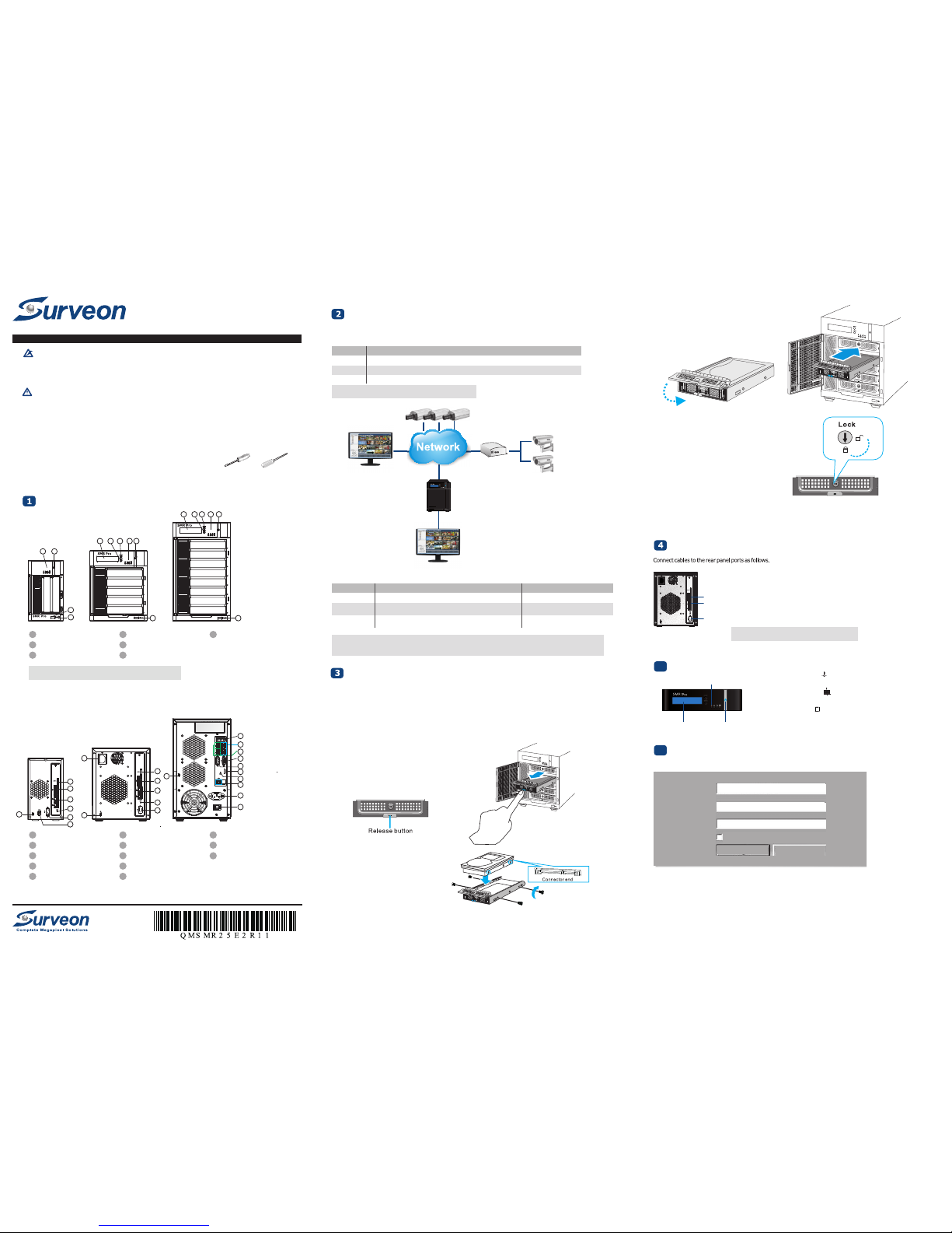
Inserting Hard Drive into Drive Tray
1. Open the front panel of the SMR system.
2. Press the release button (indicated by the blue arrow)
on the bezel, the bezel panel should open automatically
and gently pull out the hard drive tray.
3. Place the hard drive into the drive tray.
Make sure the hard drive’s interface
connector is facing the open side of the
drive tray and its label side facing up.
Adjust the drive’s location until the
mounting holes in the drive tray are aligned
with those on the hard drive. Secure the
drive with four supplied flat head screws.
System Diagram
SMR Series
IP Cameras
Analog Cameras
IP Encoder
VGA Management Station
& Live View
Remote Client
(Optional)
Note: Users can only use the upper LAN port.
USB Port
Upper
LAN Port
VGA Port
• Insert mouse, keyboard or other external devices to the USB port to operate
the Video Management Software (VMS).
• Insert the LAN cable to the upper LAN port to connect the SMR to a local
network where your IP cameras reside. (Connection to analog cameras is
also available via an IP encoder.)
• Connect an external monitor capable of 32bit or higher color quality to the
VGA Port to view the VMS interface.
• VMS/NVR – Local host for the SMR Server, which can not be changed.
• Username – The username for the domain, which is always admin.
• Password – The password for the domain. Default password is admin.
Cabling
The VMS Cli ent wi ll pro mpt for the f ollowi ng info rmatio n afte r the S MR sys tem is powere d on:
Clic k Login aft er the passwo rd is entered .
Plea se tur n over the pa ge and contin ue the insta llation proce ss.
Log gin g i nto SM R
6
LED Indicators
LCD Display Power Switch
1. Press the Power Switch.
2. See if the System LED is blinking, which means that the
system is starting up.
3. See if the Network LED has turned green, which indicates
that power is on and network is connected.
4. See if the HDD LED is on, which means that the hard drive
can be accessed.
5. The Server name and the IP address will be shown on the LCD
screen (SMR5000/8000 series).
Pow eri ng up SMR
5
VMS/NVR:
Username:
Password:
Auto Login
Login Shut Down
Local Host - 127.0.0.1
admin
Overview
Front View
SMR5000 Series
SMR8000 Series
1 LCD Display
2 Enter Switch
3 Select Switch
4 LED Indicators
5 Power Switch
67Front USB Connector
Video Back Up Button
SMR2000 Series
Rear View
SMR2000 Series
SMR5000 Series
SMR8000 Series
1 Power Socket
2
3
4
5
6
2
3
4
3
4
1
5
5
6
6
9
10
11
12
13
7
4 5
1 2 3 4 5
1 2 3 4 5
8
8
8
1
2 e-SATA Port x1
3 USB Port x4
4
5
6 VGA Port
7
8 Kensington Lock-hole
9 COM Port
10 HDMI Port
11
LAN Port (GbE Ethernet port) x2
Restore Button
12V DC Power Port
USB Port x2
12
Safety Switch
13
Audio Ports
Note: The function of Video Back Up Button is reserved.
6
6 6
7
4. With the tray bezel open, insert the hard drive and
tray into the system enclosure.
5. Close the tray bezel.
6. Use the small flat blade screwdriver to turn the bezel lock
from the unlock to lock position.
7. Repeat above steps to install other hard drives.
8. Close the system front panel when you are done installing hard drives.
Page 2
Step4: Display Resolution
Step1: Install Wizard
Step2: Storage Manager
Step3: Initialize the System
Step5: Change Password
Step8: Add Cameras
Step6: Time Settings
Step7: Network Settings
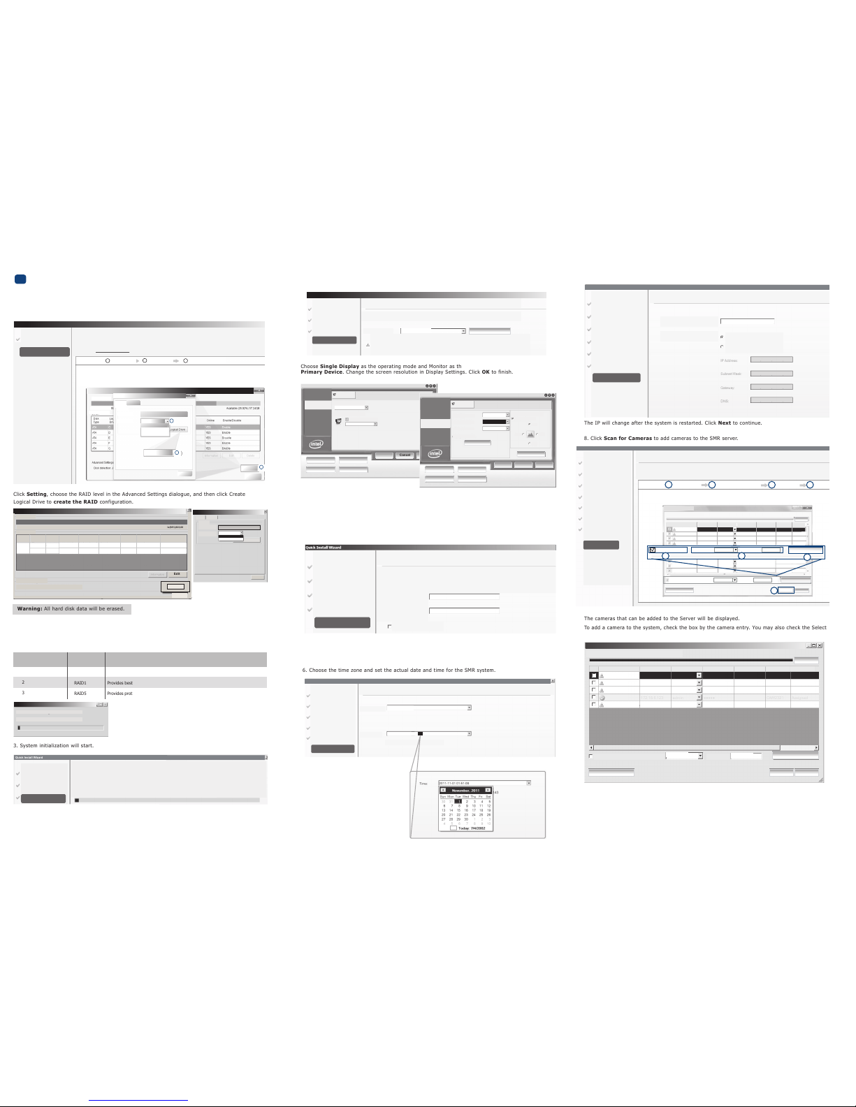
Quick Install Wizard
Step7: Network Settings
SMR Server Name:
SMR Server
SMR Server IP Address:
Obtain IP Address from DHCP
Fixed IP Address
3. Sy stem i nitial izatio n will start.
The system will s hut do wn aft er the initia lizati on is done su ccessf ully. Pl ease c lick OK .
Pres s the p ower s witch to res tart th e syst em. Ab out 1.5 minut es lat er, the W izard w indow will
pop again.
Step3: Initialize the System
Initialization System
Initialization will start automatically for enabling the system to achieve the best performance
Progress completed 2%
Step1: Install Wizard
Step2: Storage Manager
Step3: Initialize the System
7. Set an IP addre ss for the SM R Serv er. Obtai ning th e IP a ddress from D HCP is recomm ended.
8. C lick S can fo r Came ras to add c ameras to the SMR se rver.
9. C lick F inish to end the wi zard.
10. The VMS will start automa tically after the w izard i s fini shed. Please refer to SMR User
Manu al for more d etails .
The IP wil l chang e afte r the system is res tarted . Click Next to con tinue.
The cameras that can be added to the Serve r will be dis played .
To add a came ra to the sy stem, c heck t he box by the camer a entry. You may also check t he Sel ect
All box at the bo ttom o f the w indow to sel ect al l the camera s found .
Ente r the usernam e and passwo rd, and press Apply Selec ted. Click OK to a dd the selec ted
came ras to the Se rver.
Quick Install Wizard
Scan for Cameras
Status: Scan Complete
Select/Deselect All Username:
Password:
Rescan
OK
Apply Selected
IP Camera Utility
Cancel
Camera Name IP Address Username Password Vendor Model Status
CAM2321 New
New
New
Admin
Admin CAM2320
CAM2321
CAM2321
CAM2320
CAM2321
Mega-Pixel Network
CAM2321
New
IP8161
●●●●
●●●●
●●●●
●●●●
Admin
Admin
admin
●●●●172.18.6.57
172.18.6.147
172.18.6.159
172.18.6.164
If y ou want to ke ep usin g the defaul t passw ord, p lease tick U se old passw ord.
Clic k Next to co ntinue.
4. T he reco mmende d moni tor res olutio n for the SMR is 12 80x102 4. Clic k Open Resol ution Tool t o
chan ge the resolu tion s etting.
Choo se Sin gle Di splay as the operat ing mo de and Monito r as t he dis play se lectio n in
Prim ary De vice. Change the sc reen r esolut ion in Displa y Sett ings. C lick O K to f inish.
5. T he defa ult pa ssword for SM R logi n is ad min. I f you want to chang e the passwor d, ple ase
ente r a new one i n both the b lanks o f New Passwo rd and Confi rm.
Clic k Next to co ntinue.
Monitor
Display Devic es
Operatin g Mod e
Display Selec tion
Single Di splay
Monitor
Display Setti ngs
Intel
®
Graphics Medi a
Accelera tor D river
Color Co rrect ion
Hot Keys
Primary De vice
OK
Cancel Apply
3D Settings
Scheme Options
Video Overlay
Video Settings
Display Setti ngs
Intel
®
Graphics Medi a
Accelera tor D river
Color Co rrect ion
Hot Keys
Display Devic es
Monito r
3D Settings
Scheme Options
Video Overlay
Aspect Ratio Options
Advanced Settings
Video Settings
OK
Cancel Apply
Rotation
Enable Rot ation
Color Qual ity
Screen Res olutio n
Refresh Ra te
Display Expan sion
32 Bit
75 Hertz
1280 x102 4
0°
180°
0°
0°
270°
90°
6. Choose the ti me zon e and s et the actua l date and ti me for the S MR syst em.
Step4: Display Resolution
Step1: Install Wizard
Step2: Storage Manager
Step3: Initialize the System
Step5: Change Password
Step6: Time Settings
Quick Install Wizard
Step6: Time Settings
Time
Time Zone
Current System Time 2002-07-04 01:52:08
(UTC+08:00) Taipei
2011-11-01 01:51:09
Clic k Next to co ntinue.
Quick Install Wizard
Step5: Change Password
Username:
New Password:
Confirm:
Use old password
Admin
Step4: Display Resolution
Step1: Install Wizard
Step2: Storage Manager
Step3: Initialize the System
Step5: Change Password
Step1: Insta ll Wi zard
Step2: Stora ge Ma nager
Step3: Initi alize the S ystem
Step5: Chang e Pas sword
Step4: Displ ay Re soluti on
Quick Install Wizard
Step4 : Disp lay R esolut ion
Choose at le ast 1 280x10 24 fo r an o ptima l View.
If the resolu tion is low er th an 128 0x1024 , the scree n may not b e abl e to a ccomm odate some o f the items .
Displa y Sett ings
1280x1 024
Open Resolution Tool
Thes e are t he RAI D opti ons for SMR m odels.
2
2
3
Minimum Hard Drives RAID Options Descriptions
RAID0 Provides no protection, but offers maximum capacity.
Provides best protection. Your data will be mirrored.
Provides protection against one drive failure.
RAID1
RAID5
Create Logic al Dr ive
Please Wait. .. Thi s mig ht tak e seve ral m inutes .
Curren t prog ress 2%
Plea se cli ck OK a fter t he con figurat ion is done, and th e syst em wil l reboo t auto matica lly.
Abou t 2 min utes l ater, the Wizar d wind ow will appea r agai n. Clic k Next to co ntinue .
Warn ing: A ll har d disk data w ill be erased .
Clic k Sett ing, c hoose t he RAI D leve l in th e Adva nced Se ttings dialo gue, an d then click Create
Logi cal Dri ve to create the R AID co nfigura tion.
Storage Manager
Storage Usage
Advanced Settings
Disk detention, join NOR Server allocation
Edit
Detail
Disk
Type
USB C --3594
204
D
USB
Logical
Drive
RAID
Level
Data Type
Online
Used(100%)3.51GB Available(98%)923,66
Advanced Setting
Close
General
RAID
IP Storage
Logical Drive
0
1
0
Free Space
RAID Level
476950(MB)
Drive
Storage(MB)
OS APP
NO YES
YES
Enable Disable
Enable
Enable
Status
Normal
Normal
668
182
Available
Size(MB)
Close
Settings
2. C lick S torage Manag er to do RAI D confi gurati on.
Storage Manager
Advanced Settings
Step1: Install Wizard
Step2: Storage Manager
Please open storage manager to do RAID configuration for the disks installed.
1 Click”Setting”
2 Choose the RAID level, and then click”Create Logical Drive” to create the RAID configuration.
Step2: Storage Manager
Open the
Storage Manager
Operating Steps
Setting
1
2
RAID Level
Create Logical Drive
3
General
Storage Usage
2
Used(73.98%
Detail
lP Srorage
Close
Close
Setting
2626162(MB)
RAID
Free Space
RAID Level
Creat Logical Drive
1
3
Quick Install Wizard
Step4: Display Resolution
Step3: Initialize the System
Step5: Change Password
Step8: Add Cameras
Step6: Time Settings
Step7: Network Settings
When you ru n the SMR se ries fo r the first time, y ou nee d to g o throu gh the follo wing st eps
with in the Quick Instal l Wiza rd afte r logg ing in .
1. Make sure t he har d drive s are insert ed into the S MR cas e. Cli ck Next to c ontinue .
Ins tal l W iza rd
7
Step1: Install Wizard
Step2: Storage Manager
Step8: Add Cameras
Step4: Display Resolution
Step3: Initialize the System
Step5: Change Password
Step6: Time Settings
Step7: Network Settings
Step8: Add Cameras
The ‘scan camera’ will add cameras into system into system automatically.
Operating Steps
OK
Select Cameras Enter Username and Password
Apply Select
OK
Quick Install Wizard
1
2 3
4
4
Select the cameras you want, enter the correct username and password, and the press Apply Selected.Click OK to add the
selected cameras to the Server.
Scan for camera
Username: Admin
Password: ●●●●
Rescan
Apply Selected
IP Camera Utility
CAM2320
CAM2320
CAM6120
IP CAM
IP CAM
IP CAM
172.16.80.8
172.16.80.9
172.16.80.9
172.16.80.240
172.16.80199
Username
Admin
Admin
Admin
Admin
Admin
Admin
Password
●●●●
●●●●
●●●●
●●●●
●●●●
●●●●
Model
CAM2320
CAM2320
CAM6120
CAM2101
CAM4365
CAM2321
Status
New
New
New
New
New
New
Vendor
Scan for camera
Status: Scan Complete
Cancel
Select/Deselect All
CAM3260
172.16.80199
Admin ●●●●
CAM3260
New
Camera Name IP Address
Username: Admin Password: ●●●●
Apply Selected
2
Select/Deselect All
172.16.80.240
3
1
0
1
5
1
 Loading...