

Page 1
War nin g
QMN R 7 8 X 0 0 1 1 0
NV R7800 Serie s
Qu ick Insta lla tio n Guid e
• Onl y quali fied se rvice p erson nel sho uld ins tall an d servi ce this p roduc t to avoi d injur y.
Obs erve al l ESD pro cedur es duri ng inst allat ion to av oid dam aging t he equi pment .•
1
Pre parin g Tools
2
• Phi llips s crewd river ( mid-s ize)
• Fla t blade s crewd river ( small -size )
• Ant i-sta tic wri st wrap
Warni ng
Due to t he weig ht of the e nclos ure and i nstal latio n proce dure re quire ments , DO NOT
inst all HDD s befor e rackm ounti ng and at l east on e other p erson nel sho uld ass ist wit h
the in stall ation .
Unp ack the e quipm ent and m ake sur e the fol lowin g tools a re avai lable b efore i nstal latio n.
5
2
3
4
6
7
8
1
9
Item
Desc ripti on
Quant ity
01
02
03
04
05
06
07
08
09
Mounting bracket assembly, left-side
Mounting bracket assembly, right-side
Inner glides
Flathead screws #6-32 L4
Truss head screws M5 x 9.0mm
M5 cage nuts
M5 x 25mm
M6 x 25mm
#10-32 x 25.4mm
1
1
2
6
8
4
4
4
4
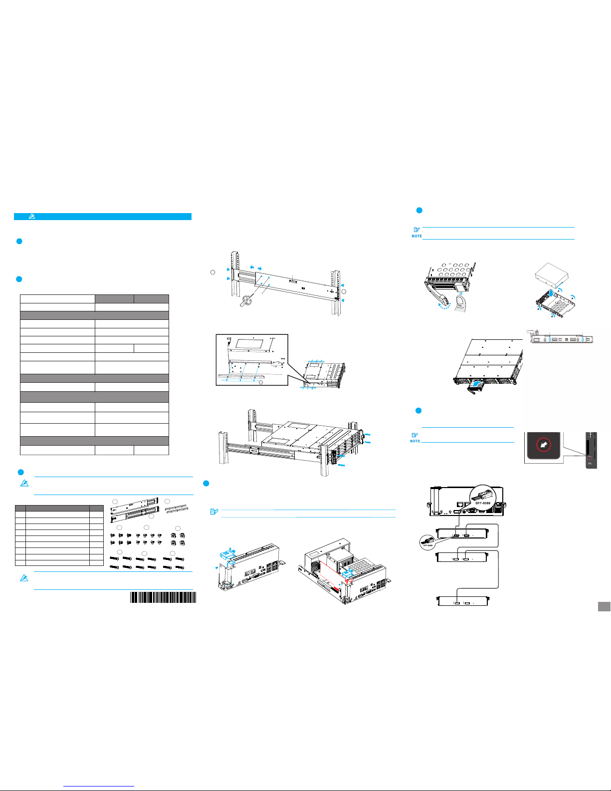
1. Det ermin e the exa ct posi tion fo r enclo sure in stall ation ( front a nd rear r ack pos ts).
2. Ref er to the i llust ratio n below t o inser t cage nu ts into t he fron t rack po st and tr uss hea d screw s to secu re
the sl ide rai l.
Pos ition s for cha ssis / M5 c age nut : Pleas e refer t o Rack Ea r Mount K it’s se ction .
3. Adj ust the l ength b y loose ning th e four sc rews on t he slid e rail. S ecure t he slid e rails t o front a nd rear
post s using t russ he ad scre ws and ti ghten t he four s crews o n the sli de to fix t he leng th.
4. Att ach the i nner gl ides to B OTH sid es of the e nclos ure usi ng flat head sc rews #6 -32.
M5 x 9.0mm
05
M5 x 9.0mm
05
Inner g lide ra il
#6-32
08
3
333
3
3. Ins ert the c ontro ller ba ck into t he encl osure , secur e the scr ews und ernea th both l evers .
At le ast fou r (4) har d drive s must be i nstal led for R AID 5 or fi ve (5) ha rd driv es
mus t be inst alled f or RAID 6 t o creat e an init ial vol ume!
To insta ll the PCI -E card , you nee d to remov e the con troll er, pleas e refer t o the pre vious se ction o n how to rem ove
the co ntroll er from t he encl osure .
Please co nfirm with su pport pers onnel on PCI- E card qualif ication be fore purcha se / installa tion!
NOTE
1. Loo sen the s crews a nd remo ve the
cove rs show n in the il lustr ation b elow.
2. Ins tall th e PCI-E c ard int o PCI-E s lot, se cure it w ith
the co ver and s crews .
4
5
4
5
4
4
Pres s the rel ease bu tton to o pen the b ezel
and ge ntly pu ll the HD D tray ou t of the en closu re.
a.R emovi ng the HD D tray
b. Att achin g the HDD
1. The i nterf ace con necto r shoul d face th e open si de of
the tr ay, whi le the la bel sid e shoul d face up .
2. Sec ure the d rive by f asten ing fou r (4) of th e suppl ied
scre ws.
5-2 . Inser ting an d Secur ing HDD t ray
Inse rt with t ray bez el open .
7
6-1 . Setti ng JBOD I Ds
JBO D enclo sure ID (s). A diffe rent ID n umber
mus t be allo cated f or each J BOD.
Use a s mall fl at blad e screw drive r to set th e
0
2
4
6
8
10
12
14
0
2
4
6
8
10
1
2
14
EonS erv is as signe d with ID “ 0" by def ault.
2U sys tem con nects o nly to 2U J BODs.
3U sys tems co nnect o nly to 3U J BODs.
1st JBOD
2nd JBOD
.
.
.
.
.
.
.
Last JBOD
6-2 . Makin g conne ction s
• 1st JB OD SAS- OUT– 2n d JBOD SA S-IN
• EonS erv SAS e xp. – 1st J BOD SAS -IN
5. Wit h the ass istan ce of ano ther pe rson, l ift and i nsert t he encl osure o nto the s lide ra il. Mak e sure th e inner g lides
on bot h sides o f the enc losur e meets t he inne r glide r ail. Se cure th e enclo sure us ing M5 or M 6 screw s from th e front .
3-1 . Slide R ail Kit C onten ts
Rac kmoun t Insta llati on
3
Mat erial s Check ing Lis t
2
Abov e box con tents a nd quan titie s are sta ndard s hipme nt, and m ay vary b ase on or der req uests
.
.
3-2 . Insta llati on
5-1 . Stand ard for m facto r HDD(3 .5'’)
PCI e Card In stall ation (Opti onal)
4
NVR7 812
NVR7 816
Box co ntent s
Quan tity
Acce ssory b ox
Quic k Insta llati on Guid e
Powe r cord
Scre ws for se curin g 3.5'’ H DDs
Powe r clamp s et
Scre ws for mo untin g enclo sure:
M5*4 /M5 NUT *4/M6 *4/31 0-32* 4
Powe r cord bo x
Encl osure c hassi s
Pre- insta lled mo dules i nclud e:
Cont rolle r modul e with OS h ard dri ves
Powe r suppl y unit (P SU) w/e mbedd ed
FAN mod ule
Prod uct DVD
Tray E PE5
HDD Tra y
12
16
1
1
16
2
1
2
2
50 70
JBO D Conne ction s
6
Ins talli ng HDD
5
Ref er to the f ollow ing tab le for th e exact a mount o f items i nclud ed in the p ackag e.
.
RS 232 S erial c able( mini US B to DB-9 )
1
NOT E
In the 3 -1 Slid e Rail Ki t Conte nts Table , items 3 ~5 are pl aced wi th the it em 2
(Mou nting b racke t assem bly, rig ht-si de) as a pa ckage . Items 6 ~9 are pu t into th e
Acce ssory b ox as Mat erial C hecki ng List s hows. ( pleas e refer t o Point 2 AS A BOVE) .
1/4
Page 2
Con troll er LEDs :
1. Ct rl Stat us LED: O n ( )
2. C_ Dirty L ED: Off
3. Ho st Busy L ED: On ( )
gre en
gre en
1 2 3
PSU L ED:
• PSU L ED: On ( )gre en
8
7-2 . Power ing up th e equip ment
1. Pow er up the n etwor king de vices .
2. Pow er up the J BODs (i f appli ed) by pr essin g the pow er swit ches on t he rear p anel.
3. Pow er up the E onSer v syste m by swit ching o n both po wer swi tches ( shown a bove in )
on the r ear pan el and pr ess the b utton o n the fro nt pane l.
4. Pow er up the a pplic ation s erver s.
gree n
8-1 . Overv iew of co nnect ion int erfac es
USB 3.0
por ts
USB 2.0
por ts
HDMI 1
HDMI 2
JBO D SAS
exp ansio n
D-S ub
VGA po rt
Eth ernet
por ts
Eth ernet
por ts
PCI e Card
Slo t (opti onal)
8
8
7-3 .
Obs erve th e front o f the enc losur e. If the L ED indi cator s show di ffere nt stat us than
des cribe d below , or if you h ear an au dible a larm, p lease c ontac t custo mer sup port.
Ver ifyin g statu s LEDs (f ront of e nclos ure)
Fro nt pane L EDs:
Syst em LED: G reen
Serv ice LED : Off
Powe r LED: Gr een
Cool ing fan L ED: Gre en
Ther mal LED : Green
Dri ve tray :
• Pow er Stat us LED: O n ( )gre en
7-4 .
Obs erve th e rear of t he encl osure . If the LE D indic ators s how dif feren t statu s than
des cribe d below , or if you h ear an au dible a larm, p lease c ontac t custo mer sup port.
Ver ifyin g the sta tus LED s (rear o f enclo sure)
88
7-1 .
Conn ect the p ower co rds to th e power s ocket ( in ) on bot h PSUs.
Con necti ng the po wer cor d
blue
7
7
4
6
6
6
7
8
7
3
Not e
For d etail ed info rmati on of OS dr ive repl aceme nt, ple ase ref er to t he 10th c hapte r of
NVR 7800 Se ris Man ual.
Ther e are two 2 .5 inch SA TA hard d rive on th e contr oller t hat mad e into RAI D 1 to incr ease the s ecuri ty of OS
driv e.
Two me thods c ould det ect the h ealth s tatus of O S drive .
The In tel too l will di splay t he stat us as “De grade d” inst ead of “N ormal o n the scr een.”
If the l ocati on show s as “Con troll er 0, Por t 2”, it st ands fo r the har d disc of s lot 2 (as A a rea sho ws) is da maged ,
If the l ocati on show s as “Con troll er 0, Por t 3”, it st ands fo r the dis c of slot 3 ( as B area s hows) i s damag ed.
(Ple ase ref er to the p ic. on th e upper r ight si de of thi s page. )
3
9
A
B
If the re is disc e rror, t he warn ing sign al will a ppear i n the wind ows eve nt log.
3
The d amage w arnin g notic e and rep lacem ent pro cedur es are as
fol lowed :
333
3. Loo sen the s crews on t he leve r, push t he lever s down to r emove t he contr oller o ut of the e nclosu re.
4. De part th e damag ed HDD ba sed on th e infor matio n you hav e. Loos e the thu mb scre ws on the
tra y and gen tly pul l out the t ray fro m the cag e.
6. Ins ert the c ontro ller ba ck into t he encl osure , secur e the scr ews und ernea th both l evers .
4
4
5
When e ither O S drive i s broke n, repla ce by PUL LING th e damag e
unit O UT then re placi ng with a n ew one to e nsure b eing pro tecte d
by RAI D1.
7. Fin ally, in sert th e contr oller b ack int o the enc losur e then re boot th e compu ter to en able RA ID 1 mirr or the fu nctio ns of the h ard dis c , secur e the scr ews
unde rneat h both le vers.
If you e ncoun ter 2 OS dr ives ar e damag ed simu ltaneo usly,
plea se cont act wit h FAE.
A
B
7
9
1. Con firm wh ich OS dri ve is dam aged by I ntel RST e AHCI& SCU Sof tware RA ID Driv er
2. Tur n off the N VR780 0 subsys tem.
5. In stall t he hard d rive in to the tr ay, ins ert it ba ck into
the c age, ti ghten t he thum b screw s.
9
8
999
3
Warni ng
Alw ays ins tall th e top hard d rive fi rst!
9-1 . Metho d One Int el RSTe AHC I&SCU S oftwa re RAID D river
9-2 . Window s Event L og
Leve l
Date a nd Time
Sour ce
Task Cat egory
Warni ng
2/18 /2016 3 :34:3 2PM
elre xpres s
27
None
Inte l(R)I 210 Gig abit
Netw ork
Conn ectio n#6
Netw ork lin k is
disc onnec ted
Warni ng
2/18 /2016 3 :34:3 2PM
elre xpres s
27
None
Inte l(R)2 10 Giga bit
Netw ork
Conn ectio n#5
Netw ork lin k is
disc onnec ted
Warni ng
2/18 /2016 3 :34:3 2PM
elre xpres s
27
None
Inte l(R)2 10 Giga bit
Netw ork
Conn ectio n#4
Netw ork lin k is
disc onnec ted
Even t ID
Inte l RSTe AHCI &SCU So ftware R AID DRI VER is pl aced in
Prod uct CD.
Tro uble- shoot ing
OS Dr ive Rep lacem ent
9
Con necti on Inte rface s
8
Pow ering U p
7
2/4
Page 3

The Comparisons between XProtect Enterprise/Corporate are listed in the following chart.
Milestone XProtect Installation
Software Installation
2-1. After the installation is complete, double-click the Smart Client shortcut on your desktop or select Start >
Programs > Milestone XProtect Smart Client > Smart Client from Windows Start Menu to start the software.
2-2. The Smart Client login window will prompt.
3. Adjust Motion Dection...
Starting Milestone XProtect Smart Client
Connect to Server
3. Adjust Motion Dection...3. Adjust Motion Dection...
The Milestone XProtect Enterprise/Professional/Corporate Management Application Windows will
prompt on the monitor display connected to the NVR78XX Series after powering on.
3. Adjust Motion Dection...
Basic System Settings through Wizards
3. Adjust Motion Dection...3. Adjust Motion Dection...
3. Adjust Motion Dection...
Note: For more details about the Wizards and Management Application, please refer to Milestone XProtect
Enterprise/Professional/Corporate Administrator’s Manual.
3. Adjust Motion Dection...
Note: If you install the Smart Client on a remote PC, you will be authenticated through your current Windows
login by default, and do not have to specify any user name or password. Please refer to Milestone
XProtect Enterprise/Corporate Administrator’s Manual for more details.
3. Adjust Motion Dection...
Use the wizards to configure the surveillance system:
3-1. Cameras and other hardware devices, such as Video encoders, NVRs, etc. can be added to your
XProtect system through the Add Hardware Devices wizard. If microphones/speakers are attached to
a hardware device, they are automatically added as well.
3-2. You can quickly configure your cameras' video storage through Configure Video Storage wizard.
3-3. The Adjust Motion Detection wizard helps you quickly configure your cameras' motion detection
properties.
3-4. The Manage User Access wizard helps you quickly configure clients' access to the XProtect
server as well as which users should be able to use clients.
3. Adjust Motion Dection...
EonOne Lite Installation
Key Features
3. Adjust Motion Dection...
Number of Connected Cameras
3. Adjust Motion Dection...
Maximum Number of Users
3. Adjust Motion Dection...
Video Export Format
3. Adjust Motion Dection...
Web Client
3. Adjust Motion Dection...
Archiving to Network Storage
3. Adjust Motion Dection...
3rd Party Application Integration
3. Adjust Motion Dection...
Support for Video Analytics
3. Adjust Motion Dection...
Scalable Multi-server Solution
3. Adjust Motion Dection...
Alarm Manager
3. Adjust Motion Dection...
Map Function
3. Adjust Motion Dection...
Centralized Management
3. Adjust Motion Dection...
Flexible Event Rule Wizard
3. Adjust Motion Dection...
Failover Servers
3. Adjust Motion Dection...3. Adjust Motion Dection...3. Adjust Motion Dection...3. Adjust Motion Dection...3. Adjust Motion Dection...3. Adjust Motion Dection...3. Adjust Motion Dection...3. Adjust Motion Dection...3. Adjust Motion Dection...3. Adjust Motion Dection...3. Adjust Motion Dection...
XProtect Enterprise
3. Adjust Motion Dection...3. Adjust Motion Dection...
Unlimited
3. Adjust Motion Dection...
JPEG, AVI, Native Database
3. Adjust Motion Dection...
Yes
3. Adjust Motion Dection...
Yes
3. Adjust Motion Dection...
Yes
3. Adjust Motion Dection...
Yes
3. Adjust Motion Dection...
Yes
3. Adjust Motion Dection...
Yes
3. Adjust Motion Dection...
Yes
3. Adjust Motion Dection...
XProtect Corporate
3. Adjust Motion Dection...3. Adjust Motion Dection...
Unlimited
3. Adjust Motion Dection...
JPEG, AVI, Native Database
3. Adjust Motion Dection...
Yes
3. Adjust Motion Dection...
Yes
3. Adjust Motion Dection...
Yes
3. Adjust Motion Dection...
Yes
3. Adjust Motion Dection...
Yes
3. Adjust Motion Dection...
Yes
3. Adjust Motion Dection...
Yes
3. Adjust Motion Dection...
Yes
3. Adjust Motion Dection...
Yes
3. Adjust Motion Dection...
Yes
2-3. Specify your login information in the following fields:
• Computer: Please choose Localhost.
• Authentication: Choose Windows authentication. (current user)
• User name: Leave it as a blank. The user name can be changed later.
• Password: Leave it as a blank. The password can be changed later.
When ready, click Connect.
2-4. The Smart Client window will open.
Go to C:\XProtect Enterprise\ or C:\XProtect Corporate\ and double-click the installation file.
Choose Install Trial and follow the instructions to start the installation.
Choosing Milestone XProtect Level
Installing Milestone XProtect
Note: (1) The trial version can be used for 30 days. Also, video channels are limited to eight as the maximum.
(2) Milestone XProtect Smart Client CANNOT be installed on the same PC with NVR7800.
4.1. You are recommended to log in to your computer as an administrator or the root user before launching
the installation/ installation process.
4.2. On the operating system of the host server or the NVR7800, download the installation package from Infortrend and
unzip the downloaded file. Double click the “setup.exe” in the extracted folder to launch the
installation wizard.
Accessing MilesLevel
4.3. Click the EonOne Lite shortcut on your Desktop to launch the web-based EonOne Lite interface, or go to
either of the following addresses using a web browser:
HTTP access: http://127.0.0.1:8816/
HTTP access: https://127.0.0.1:8817/
4.4. When login screen appears, enter the username and password, then click ”LOGIN”. The default username
and password are “admin.”
Note: EonStor Lite can run on the following platforms.
(1) An EonStor DS storage subsystem(firmware version 2.1 or later) connected to a host server via
in-band connection(through the FC/iSCSI port of the storage subsystem.)
(2) An NVR7800 system.
(3) Please refer for EonOne Lite Installation Manual for further information.
SSL Lo gin is en abled b y defau lt.
4.5. When the login process is complete, the Overview page of EonOne Lite will appear.
Quick Setup
You can see the front view and indicator lights of the storage device or JBODs (if any) displaying the device
and hard drives status.
To the right of the front view, you can see the RAID level and capacity of the partition which is about to created
from the newly added storage device and its connected JBODs (if any).
Ste p 1
5.6. When the login process is complete, the Overview page of EonOne Lite will appear. When you access
EonOne Lite for the first time, a Start Quick Setup wizard will show up for configuring storage device guidance.
Con figuri ng new partit ion
150
150
2 1
2
4
3
3
3/4
Page 4

6
6-2. Insert the USB drive to PC(s).
6-3. Double-click the installation files and follow the instructions to start the installation.
Ste p 2
Crea ting a p artit ion
Click Apply to continue with the next step, which enables the system to create a new partition based on the settings
you configured in the previous step.
Ste p 3
Fin ishing Quick Setup
Installing Milestone XProtect Smart Client/SANWatch
on Remote PC(s) (Optional)
7
Installation File Information
1. For installation file of Milestone XProtect Enterprise, will be found in C:\Milestone XProtect\
2. For installation file of Milestone XProtect Corporate, will be found in C:\Milestone XProtect\
3. For installation file of Genetec, will be found in C:\Genetec\
4. For installation files of EonOne Lite and SANWatch, will be found in C:\Surveon\
SANWatch Installation (Optional)
Installing SANWatch
If you have installed Eonstor DS RAID subsystem(s), please install SANWatch for storage management.
5-1. After installation is initiated, you will be guided to the Infortrend SANWatch Setup Wizard. Click Next to continue.
5-2. The installation program asks for Full or Custom installation. You can also select the installation folder here.
Choose Full installation if you intend to manage SANWatch directly from the host computer. Skip to 4.4 directly.
Software Registration Service Center
5-3. If choosing Custom installation, and in component list corver, select the module you need based on the
If you are using DB Flush Agent for taking snapshot images with database applications, select Data Host Agent
and/or Out-of-Band Flush Only. Click Next to continue.
5.4. Select if you want to install SANWatch in a single host computer or redundant host computers. For the redundant mode,
specify the IP addresses of the master and slave host computers. If you choose to manage you RAID subsystem network
using dual computers, it is strongly recommended you install and log in to SANWatch on the master host first, and make sure
it’s online before installing SANWatch on the slave-host.
5-5. When the installation has completed, restart the computer.
Note: This section instructs you how to install the whole GUI-based SANWatch on various OS platforms.
(2) If you choose NOT to install the Java provided by the installation CD, make sure you already have Java 6
or later installed on your computer. Please refer to SANWatch User Manual for more details.
4
4
7
6
7
7
5
Inte l RSTe AHCI &SCU So ftware R AID DRI VER is pl aced in
Prod uct CD.
4/4
 Loading...