

Surveon NVR7812, NVR7816 Quick Installation Manual
War nin g
QMN R 7 8 X 0 0 1 1 0
NV R7800 Serie s
Qu ick Insta lla tio n Guid e
• Onl y quali fied se rvice p erson nel sho uld ins tall an d servi ce this p roduc t to avoi d injur y.
Obs erve al l ESD pro cedur es duri ng inst allat ion to av oid dam aging t he equi pment .•
1
Pre parin g Tools
2
• Phi llips s crewd river ( mid-s ize)
• Fla t blade s crewd river ( small -size )
• Ant i-sta tic wri st wrap
Warni ng
Due to t he weig ht of the e nclos ure and i nstal latio n proce dure re quire ments , DO NOT
inst all HDD s befor e rackm ounti ng and at l east on e other p erson nel sho uld ass ist wit h
the in stall ation .
Unp ack the e quipm ent and m ake sur e the fol lowin g tools a re avai lable b efore i nstal latio n.
5
2
3
4
6
7
8
1
9
Item
Desc ripti on
Quant ity
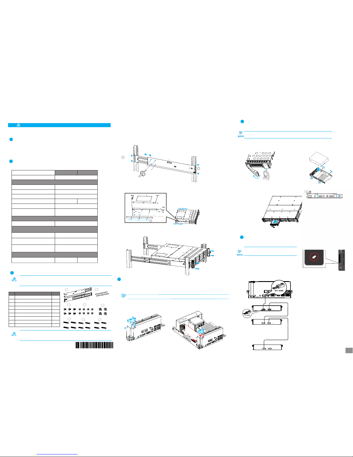
01
02
03
04
05
06
07
08
09
Mounting bracket assembly, left-side
Mounting bracket assembly, right-side
Inner glides
Flathead screws #6-32 L4
Truss head screws M5 x 9.0mm
M5 cage nuts
M5 x 25mm
M6 x 25mm
#10-32 x 25.4mm
1
1
2
6
8
4
4
4
4
1. Det ermin e the exa ct posi tion fo r enclo sure in stall ation ( front a nd rear r ack pos ts).
2. Ref er to the i llust ratio n below t o inser t cage nu ts into t he fron t rack po st and tr uss hea d screw s to secu re
the sl ide rai l.
Pos ition s for cha ssis / M5 c age nut : Pleas e refer t o Rack Ea r Mount K it’s se ction .
3. Adj ust the l ength b y loose ning th e four sc rews on t he slid e rail. S ecure t he slid e rails t o front a nd rear
post s using t russ he ad scre ws and ti ghten t he four s crews o n the sli de to fix t he leng th.
4. Att ach the i nner gl ides to B OTH sid es of the e nclos ure usi ng flat head sc rews #6 -32.
M5 x 9.0mm
05
M5 x 9.0mm
05
Inner g lide ra il
#6-32
08
3
333
3
3. Ins ert the c ontro ller ba ck into t he encl osure , secur e the scr ews und ernea th both l evers .
At le ast fou r (4) har d drive s must be i nstal led for R AID 5 or fi ve (5) ha rd driv es
mus t be inst alled f or RAID 6 t o creat e an init ial vol ume!
To insta ll the PCI -E card , you nee d to remov e the con troll er, pleas e refer t o the pre vious se ction o n how to rem ove
the co ntroll er from t he encl osure .
Please co nfirm with su pport pers onnel on PCI- E card qualif ication be fore purcha se / installa tion!
NOTE
1. Loo sen the s crews a nd remo ve the
cove rs show n in the il lustr ation b elow.
2. Ins tall th e PCI-E c ard int o PCI-E s lot, se cure it w ith
the co ver and s crews .
4
5
4
5
4
4
Pres s the rel ease bu tton to o pen the b ezel
and ge ntly pu ll the HD D tray ou t of the en closu re.
a.R emovi ng the HD D tray
b. Att achin g the HDD
1. The i nterf ace con necto r shoul d face th e open si de of
the tr ay, whi le the la bel sid e shoul d face up .
2. Sec ure the d rive by f asten ing fou r (4) of th e suppl ied
scre ws.
5-2 . Inser ting an d Secur ing HDD t ray
Inse rt with t ray bez el open .
7
6-1 . Setti ng JBOD I Ds
JBO D enclo sure ID (s). A diffe rent ID n umber
mus t be allo cated f or each J BOD.
Use a s mall fl at blad e screw drive r to set th e
0
2
4
6
8
10
12
14
0
2
4
6
8
10
1
2
14
EonS erv is as signe d with ID “ 0" by def ault.
2U sys tem con nects o nly to 2U J BODs.
3U sys tems co nnect o nly to 3U J BODs.
1st JBOD
2nd JBOD
.
.
.
.
.
.
.
Last JBOD
6-2 . Makin g conne ction s
• 1st JB OD SAS- OUT– 2n d JBOD SA S-IN
• EonS erv SAS e xp. – 1st J BOD SAS -IN
5. Wit h the ass istan ce of ano ther pe rson, l ift and i nsert t he encl osure o nto the s lide ra il. Mak e sure th e inner g lides
on bot h sides o f the enc losur e meets t he inne r glide r ail. Se cure th e enclo sure us ing M5 or M 6 screw s from th e front .
3-1 . Slide R ail Kit C onten ts
Rac kmoun t Insta llati on
3
Mat erial s Check ing Lis t
2
Abov e box con tents a nd quan titie s are sta ndard s hipme nt, and m ay vary b ase on or der req uests
.
.
3-2 . Insta llati on
5-1 . Stand ard for m facto r HDD(3 .5'’)
PCI e Card In stall ation (Opti onal)
4
NVR7 812
NVR7 816
Box co ntent s
Quan tity
Acce ssory b ox
Quic k Insta llati on Guid e
Powe r cord
Scre ws for se curin g 3.5'’ H DDs
Powe r clamp s et
Scre ws for mo untin g enclo sure:
M5*4 /M5 NUT *4/M6 *4/31 0-32* 4
Powe r cord bo x
Encl osure c hassi s
Pre- insta lled mo dules i nclud e:
Cont rolle r modul e with OS h ard dri ves
Powe r suppl y unit (P SU) w/e mbedd ed
FAN mod ule
Prod uct DVD
Tray E PE5
HDD Tra y
12
16
1
1
16
2
1
2
2
50 70
JBO D Conne ction s
6
Ins talli ng HDD
5
Ref er to the f ollow ing tab le for th e exact a mount o f items i nclud ed in the p ackag e.
.
RS 232 S erial c able( mini US B to DB-9 )
1
NOT E
In the 3 -1 Slid e Rail Ki t Conte nts Table , items 3 ~5 are pl aced wi th the it em 2
(Mou nting b racke t assem bly, rig ht-si de) as a pa ckage . Items 6 ~9 are pu t into th e
Acce ssory b ox as Mat erial C hecki ng List s hows. ( pleas e refer t o Point 2 AS A BOVE) .
1/4
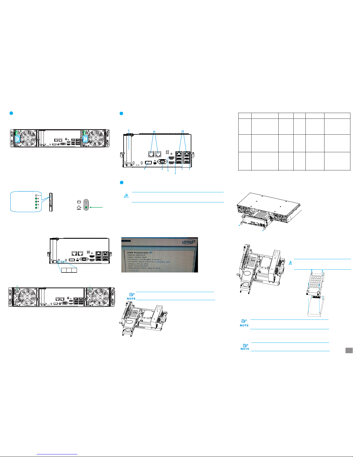
Con troll er LEDs :
1. Ct rl Stat us LED: O n ( )
2. C_ Dirty L ED: Off
3. Ho st Busy L ED: On ( )
gre en
gre en
1 2 3
PSU L ED:
• PSU L ED: On ( )gre en
8
7-2 . Power ing up th e equip ment
1. Pow er up the n etwor king de vices .
2. Pow er up the J BODs (i f appli ed) by pr essin g the pow er swit ches on t he rear p anel.
3. Pow er up the E onSer v syste m by swit ching o n both po wer swi tches ( shown a bove in )
on the r ear pan el and pr ess the b utton o n the fro nt pane l.
4. Pow er up the a pplic ation s erver s.
gree n
8-1 . Overv iew of co nnect ion int erfac es
USB 3.0
por ts
USB 2.0
por ts
HDMI 1
HDMI 2
JBO D SAS
exp ansio n
D-S ub
VGA po rt
Eth ernet
por ts
Eth ernet
por ts
PCI e Card
Slo t (opti onal)
8
8
7-3 .
Obs erve th e front o f the enc losur e. If the L ED indi cator s show di ffere nt stat us than
des cribe d below , or if you h ear an au dible a larm, p lease c ontac t custo mer sup port.
Ver ifyin g statu s LEDs (f ront of e nclos ure)
Fro nt pane L EDs:
Syst em LED: G reen
Serv ice LED : Off
Powe r LED: Gr een
Cool ing fan L ED: Gre en
Ther mal LED : Green
Dri ve tray :
• Pow er Stat us LED: O n ( )gre en
7-4 .
Obs erve th e rear of t he encl osure . If the LE D indic ators s how dif feren t statu s than
des cribe d below , or if you h ear an au dible a larm, p lease c ontac t custo mer sup port.
Ver ifyin g the sta tus LED s (rear o f enclo sure)
88
7-1 .
Conn ect the p ower co rds to th e power s ocket ( in ) on bot h PSUs.
Con necti ng the po wer cor d
blue
7
7
4
6
6
6
7
8
7
3
Not e
For d etail ed info rmati on of OS dr ive repl aceme nt, ple ase ref er to t he 10th c hapte r of
NVR 7800 Se ris Man ual.
Ther e are two 2 .5 inch SA TA hard d rive on th e contr oller t hat mad e into RAI D 1 to incr ease the s ecuri ty of OS
driv e.
Two me thods c ould det ect the h ealth s tatus of O S drive .
The In tel too l will di splay t he stat us as “De grade d” inst ead of “N ormal o n the scr een.”
If the l ocati on show s as “Con troll er 0, Por t 2”, it st ands fo r the har d disc of s lot 2 (as A a rea sho ws) is da maged ,
If the l ocati on show s as “Con troll er 0, Por t 3”, it st ands fo r the dis c of slot 3 ( as B area s hows) i s damag ed.
(Ple ase ref er to the p ic. on th e upper r ight si de of thi s page. )
3
9
A
B
If the re is disc e rror, t he warn ing sign al will a ppear i n the wind ows eve nt log.
3
The d amage w arnin g notic e and rep lacem ent pro cedur es are as
fol lowed :
333
3. Loo sen the s crews on t he leve r, push t he lever s down to r emove t he contr oller o ut of the e nclosu re.
4. De part th e damag ed HDD ba sed on th e infor matio n you hav e. Loos e the thu mb scre ws on the
tra y and gen tly pul l out the t ray fro m the cag e.
6. Ins ert the c ontro ller ba ck into t he encl osure , secur e the scr ews und ernea th both l evers .
4
4
5
When e ither O S drive i s broke n, repla ce by PUL LING th e damag e
unit O UT then re placi ng with a n ew one to e nsure b eing pro tecte d
by RAI D1.
7. Fin ally, in sert th e contr oller b ack int o the enc losur e then re boot th e compu ter to en able RA ID 1 mirr or the fu nctio ns of the h ard dis c , secur e the scr ews
unde rneat h both le vers.
If you e ncoun ter 2 OS dr ives ar e damag ed simu ltaneo usly,
plea se cont act wit h FAE.
A
B
7
9
1. Con firm wh ich OS dri ve is dam aged by I ntel RST e AHCI& SCU Sof tware RA ID Driv er
2. Tur n off the N VR780 0 subsys tem.
5. In stall t he hard d rive in to the tr ay, ins ert it ba ck into
the c age, ti ghten t he thum b screw s.
9
8
999
3
Warni ng
Alw ays ins tall th e top hard d rive fi rst!
9-1 . Metho d One Int el RSTe AHC I&SCU S oftwa re RAID D river
9-2 . Window s Event L og
Leve l
Date a nd Time
Sour ce
Task Cat egory
Warni ng
2/18 /2016 3 :34:3 2PM
elre xpres s
27
None
Inte l(R)I 210 Gig abit
Netw ork
Conn ectio n#6
Netw ork lin k is
disc onnec ted
Warni ng
2/18 /2016 3 :34:3 2PM
elre xpres s
27
None
Inte l(R)2 10 Giga bit
Netw ork
Conn ectio n#5
Netw ork lin k is
disc onnec ted
Warni ng
2/18 /2016 3 :34:3 2PM
elre xpres s
27
None
Inte l(R)2 10 Giga bit
Netw ork
Conn ectio n#4
Netw ork lin k is
disc onnec ted
Even t ID
Inte l RSTe AHCI &SCU So ftware R AID DRI VER is pl aced in
Prod uct CD.
Tro uble- shoot ing
OS Dr ive Rep lacem ent
9
Con necti on Inte rface s
8
Pow ering U p
7
2/4
 Loading...