

Page 1

Release 1.2
NVR7300 Series
User Manual
Page 2

2
Description
Date
1.0
Initial release
June 2016
1.1
SW EC3.3 released
August 2016
1.2
SW EC4.0 released
Failover / Alarm Rules Modified
December 2016
About This Document
This manual introduces the hardware components of NVR7300 series and describes
how to install them. It also provides an overview of Server surveillance
functionality, and includes the functions of Video Management Software for
operating and monitoring a Server network.
Version History
Page 3

3
All Rights Reserved © Surveon Technology 2016
Copyright Statement
No part of this publication may be reproduced, transmitted, transcribed, stored in
a retrieval system, or translated into any language or computer language, in any
form or by any means, electronic, mechanical, magnetic, optical, chemical,
manual or otherwise, without the prior written consent of Surveon Technology Inc.
Disclaimer
Surveon Technology makes no representations or warranties with respect to the
contents hereof and specifically disclaim any implied warranties of merchantability
or fitness for any particular purpose. Furthermore, Surveon Technology reserves
the right to revise this publication and to make changes from time to time in the
content hereof without obligation to notify any person of such revisions or changes.
Product specifications are also subject to change without notice.
Trademarks
Surveon and Surveon logo are trademarks of Surveon Technology Inc. Other
names prefixed with “NVR” and “SMR” are trademarks of Surveon Technology
Inc.
Microsoft Windows and Windows are registered trademarks of Microsoft
Corporation.
Linux is a trademark of Linux Torvalds.
Solaris and Java are trademarks of Sun Microsystems, Inc.
All other names, brands, products or services are trademarks or registered
trademarks of their respective owners.
Page 4

4
Table of Contents
About This Document ......................................................................... 2
Version History ................................................................................. 2
Copyright Statement .......................................................................... 3
Disclaimer ....................................................................................... 3
Trademarks ..................................................................................... 3
Table of Contents ............................................................................. 4
Safety Precautions ........................................................................... 19
Device Site Recommendations ............................................................. 19
Energy Hazards Precaution ................................................................. 20
Chapter 1. Product Overview .............................................................. 21
1.1. Features and Benefits .............................................................. 21
1.2. Specifications for the NVR7300 Series .......................................... 22
1.2.1 Hardware Specifications ........................................................ 22
1.2.2 VMS Specifications ............................................................... 23
Chapter 2. Hardware Overview ........................................................... 25
2.1. Front Panel ........................................................................... 25
NVR7316 ............................................................................. 25
2.2. Rear Panel ............................................................................ 26
NVR7316 Series ..................................................................... 26
Connection between RAID and JBOD ............................................ 27
Chassis................................................................................ 27
Internal Backplane ................................................................. 27
2.3. LED Panel & Status .................................................................. 28
LED Panel ................................................................................. 28
2.4. Drive Tray Bezel ..................................................................... 30
Drive Tray LED ...................................................................... 30
2.5. Controller ............................................................................. 31
2.5.1. Controller Type .................................................................. 31
2.5.2. Controller Connections ......................................................... 32
Page 5

5
2.5.3. Controller LED ................................................................... 33
2.5.4. Ethernet Port LEDs .............................................................. 34
2.6. PSU & Cooling Module .............................................................. 35
PSU/Cooling Module LEDs ......................................................... 36
2.7. System Monitoring Features ....................................................... 37
l2C Bus ................................................................................ 37
Audible Alarms ...................................................................... 37
2.8. Expansion Enclosure Support ..................................................... 38
Monitoring: .......................................................................... 38
JBOD Identifier: .................................................................... 38
Cooling Module Speed Adjustment: ............................................. 38
JBOD Enclosure Status Monitoring: .............................................. 38
Hot-Swapping ....................................................................... 39
Chapter 3. Software Overview ............................................................ 40
3.1. Software Introduction .............................................................. 40
3.2. Module Framework .................................................................. 41
3.3. System Architecture ................................................................ 42
3.3.1. Standalone Server (Client-Server All-in-One) ............................... 43
3.3.2. Standalone Server + Remote Client (Web Client / SPhone Client) ...... 44
3.3.3. Multiple Servers + SCC Client .................................................. 46
3.3.4. Network Requirements ......................................................... 49
Opening Ports ....................................................................... 49
Warnings / Precautions ............................................................ 49
3.4. Port Forwarding ..................................................................... 50
3.4.1. Port Forwarding for Accessing VMS Server .................................. 51
Chapter 4. Installation ...................................................................... 54
4.1. Before You Start ..................................................................... 54
4.1.1. Checklist for Operating Environment ........................................ 54
4.1.2. Checklist for Network Topology ............................................... 54
4.2. Slide Installation ..................................................................... 55
4.2.1. Slide Rail Kit Contents .......................................................... 55
Page 6

6
4.2.2. Installation Procedure .......................................................... 56
4.3. Hard Drives Installation ............................................................ 58
4.3.1. Prerequisites ..................................................................... 58
4.3.2. Hard drive Designation ......................................................... 60
4.3.3. Replacing a Hard Drive ......................................................... 61
Installing 3.5” HDD ................................................................. 61
Inserting and securing HDD tray .................................................. 62
4.4. Other Components Installation ................................................... 63
4.4.1. Installing PCIe Card (Optional) ................................................ 63
4.4.2. Replacing the Power Supply Module / Cooling Module .................... 64
4.4.3. Detecting a Failed PSU ......................................................... 64
4.4.4. Replacing Power Supply Unit .................................................. 64
4.5. Connections & Expansions ......................................................... 67
4.5.1. System Connections for Initialization ........................................ 67
4.5.2. SAS Interface ..................................................................... 68
4.5.3. Powering Up ...................................................................... 69
Connecting the power cord ....................................................... 69
Powering up the equipment ...................................................... 69
4.5.4. Status LED When Powered-on ................................................. 70
Verifying status LEDs (front of enclosure) ...................................... 70
Verifying the status LEDs (rear of enclosure) .................................. 70
PSU LED: ............................................................................. 70
4.5.5. Connecting JBOD ................................................................ 71
Setting JBOD IDs .................................................................... 71
JBOD Expansion Connections ..................................................... 71
Controller Module of JBOD Models ............................................... 73
Controller LED for JBOD Models .................................................. 74
4.5.6. Connecting Interfaces .......................................................... 75
Overview of connection interfaces .............................................. 75
4.6. Logging into NVR7300 Series ...................................................... 76
4.7. Run the Install Wizard .............................................................. 77
Page 7

7
4.8. EonOne Lite .......................................................................... 87
Chapter 5. Basic System Settings ......................................................... 89
5.1. Storage Management ................................................................ 89
5.2. Adding Cameras to the Server .................................................... 93
5.2.1. Automatic Scan for Cameras .................................................. 93
5.2.2. Manually Adding Cameras ...................................................... 95
5.3. Setting Recording Schedule ....................................................... 97
5.3.1. Recording Schedule ............................................................. 97
5.4. Setting up Live View ................................................................ 99
Chapter 6. Live View ...................................................................... 101
6.1. Live View Window Overview .................................................... 101
6.2. View Setup .......................................................................... 104
6.2.1. Switching Between Different Screen Divisions ............................ 104
Creating and Using New Screen Divisions ...................................... 104
Auto-flipping Pages ............................................................... 104
Screen Division Page Use ......................................................... 104
Fisheye View ....................................................................... 105
Fisheye Tracking ................................................................... 106
E-map ............................................................................... 107
Secondary Display ................................................................. 109
6.3. Functionality within Views ...................................................... 110
6.3.1. Object Tracking ................................................................ 110
6.3.2. Digital Zoom ..................................................................... 111
6.3.3. Instant Playback ................................................................ 111
6.3.4. Manual Recording .............................................................. 113
6.3.5. Others ............................................................................ 114
Image Settings ..................................................................... 114
Insert Image ........................................................................ 116
Insert HTML ......................................................................... 116
Send to Large Channel ............................................................ 117
Reconnect .......................................................................... 117
Page 8

8
Remove the Camera .............................................................. 118
Keep Video Length-Width Ratio / Resize to Fit Window .................... 118
Object Counting (can only be set via remote client) ........................ 118
6.4. Full Screen View ................................................................... 119
6.4.1. Entering Full Screen View ..................................................... 119
6.4.2. Exiting Full Screen Mode ...................................................... 119
Chapter 7. Server Setup .................................................................. 120
7.1. Server Settings ..................................................................... 120
7.1.1. General Server Settings ....................................................... 120
7.1.2. To Perform Notification Setting ............................................. 123
7.1.3. Scheduling Recording .......................................................... 126
7.1.4. Storage Management .......................................................... 128
7.1.5. Pre/Post Recording ............................................................ 131
7.1.6. Individual Schedule ............................................................ 132
7.1.7. EonOneLite ...................................................................... 134
Chapter 8. Camera Setup ................................................................. 135
8.1. Adding Cameras .................................................................... 135
8.1.1. Automatic Scan for Cameras ................................................. 135
8.1.2. Manually Adding Cameras ..................................................... 138
8.1.3. Managing Group ................................................................ 139
Add a group......................................................................... 139
Rename the group ................................................................. 140
Delete the group .................................................................. 140
8.1.4. Search Camera .................................................................. 141
8.2. Camera General Settings ......................................................... 142
8.2.1. General Camera Settings ...................................................... 142
8.2.2. Edit Camera ..................................................................... 145
8.2.3. OSD Settings ..................................................................... 147
8.2.4. Privacy Mask Settings .......................................................... 150
8.3. Camera Image and Quality Settings ............................................ 153
8.3.1. Camera Image Settings ........................................................ 153
Page 9

9
8.3.2. Advanced Video Settings ...................................................... 156
8.4. VI Setup .............................................................................. 159
8.4.1. Camera Motion Detection ..................................................... 160
Configuring and Editing Detection Windows .................................. 160
Deleting a Detection Window ................................................... 161
8.4.2. Object Motion Detection ...................................................... 162
Enabling or Disabling a Detection ............................................... 162
Configuring and Editing Detection Windows .................................. 162
Testing Detection Windows ...................................................... 163
Deleting a Detection Window ................................................... 163
8.4.3. Tampering Detection .......................................................... 164
Enabling or Disabling a Detection ............................................... 164
Configuring Tampering Detection ............................................... 164
Testing Tampering Detection .................................................... 165
8.4.4. Forbidden Area Detection..................................................... 166
Enabling or Disabling a Detection ............................................... 166
Configuring and Editing Detection Windows .................................. 166
Testing Detection Windows ...................................................... 167
Deleting a Detection Window ................................................... 167
8.4.5. Intrusion Detection............................................................. 168
Enabling or Disabling a Detection ............................................... 168
Configuring and Editing Detection Windows .................................. 168
Testing Detection Windows ...................................................... 169
Deleting a Detection Window ................................................... 170
8.4.6. Virtual Fence .................................................................... 171
Enabling or Disabling a Detection ............................................... 171
Configuring and Editing Detection Windows .................................. 171
Testing Detection Windows ...................................................... 172
Deleting a Detection Window ................................................... 173
8.4.7. Missing Object Detection ...................................................... 174
Enabling or Disabling a Detection ............................................... 174
Page 10

10
Configuring and Editing Detection Windows .................................. 174
Testing Detection Windows ...................................................... 175
Deleting a Detection Window ................................................... 175
8.4.8. Foreign Object Detection ..................................................... 176
Enabling or Disabling a Detection ............................................... 176
Configuring and Editing Detection Windows .................................. 176
Testing Detection Windows ...................................................... 177
Deleting a Detection Window ................................................... 177
8.4.9. Tailgating Detection ........................................................... 178
Configuring and Editing Detection Windows .................................. 178
Testing Detection Windows ...................................................... 178
Deleting a Dividing Line .......................................................... 179
Enabling or Disabling a Detection ............................................... 179
8.4.10. Go In/Out Detection .......................................................... 180
Configuring and Editing Detection Windows .................................. 180
Testing Detection Windows ...................................................... 180
Deleting a Detection Window ................................................... 181
Enabling or Disabling a Detection ............................................... 181
8.5. PTZ Settings ........................................................................ 182
8.5.1. PTZ Settings ..................................................................... 182
8.5.2. PTZ Preset Settings ............................................................ 185
Adding a Preset .................................................................... 187
Deleting a Preset .................................................................. 187
8.5.3. PTZ Patrol Settings ............................................................. 188
8.5.4. On-screen PTZ Controls ....................................................... 191
8.5.5. Directional Pad ................................................................. 191
Pan and Tilt ........................................................................ 191
8.5.6. Functional Buttons ............................................................. 192
Home ................................................................................ 192
Preset ............................................................................... 192
Auto Pan ............................................................................ 192
Page 11

11
Patrol ................................................................................ 192
Zoom ................................................................................ 192
Focus ................................................................................ 192
ESC ................................................................................... 192
8.6. Deleting a Camera ................................................................. 193
8.7. Optimizing a Camera ............................................................. 194
Chapter 9. Alarms and Events ........................................................... 196
9.1. Alarm Rules ......................................................................... 196
9.1.1. Adding an Alarm Rule .......................................................... 197
Conditions .......................................................................... 198
Sensor Input ........................................................................ 199
Clock Alarm......................................................................... 199
Disk Error ........................................................................... 200
Video Loss .......................................................................... 200
Actions .............................................................................. 200
Event Log ........................................................................... 200
PTZ Control ......................................................................... 200
Recording Controls ................................................................ 201
E-Mail ................................................................................ 201
Alarm Sound ........................................................................ 202
Video Popup / E-Map ............................................................. 203
SMS ................................................................................... 203
Relay Output ....................................................................... 204
FTP Setting ......................................................................... 205
Alarm Scheduling .................................................................. 205
9.2. Event Log ............................................................................ 207
9.2.1. Exporting a Log ................................................................. 209
9.2.2. Searching the Event Log ....................................................... 209
System ............................................................................... 209
Event Type .......................................................................... 209
Operation ........................................................................... 210
Page 12

12
Module Name ....................................................................... 210
Device Name ....................................................................... 210
User Name .......................................................................... 210
Performing a Search .............................................................. 210
9.2.3. System Alarm View ............................................................. 211
9.2.4. Overall Status ................................................................... 214
Chapter 10. Failover and Backup ....................................................... 216
Failover Topology ................................................................. 217
10.1. Multiple NVR Management ..................................................... 218
Add ................................................................................... 218
Refresh .............................................................................. 220
Delete ............................................................................... 220
10.2. Failover Management ........................................................... 221
Failover Setting .................................................................... 221
Failover History .................................................................... 225
10.3. Failover Status ................................................................... 226
10.3.1. Failover in Live View ......................................................... 226
Failover Status Icon ............................................................... 226
Failover Status & Lights .......................................................... 227
Red Status Failover Icon .......................................................... 228
10.3.2. Failover in Playback .......................................................... 229
Playback Status .................................................................... 229
Chapter 11. Search and Playback ....................................................... 231
11.1. Introduction ....................................................................... 231
11.2. Time Search ....................................................................... 232
11.2.1. Creating a Time Search ...................................................... 232
Specified Time ..................................................................... 232
11.2.2. Use of Various Views Selection ............................................. 233
11.2.3. Camera Selection ............................................................. 233
11.2.4. Timeline ........................................................................ 234
11.2.5. Playback ........................................................................ 234
Page 13

13
Capturing Screenshot ............................................................. 236
Capturing Video Clip .............................................................. 237
11.3. Backup Search .................................................................... 238
11.3.1. Creating a Backup Search ................................................... 238
Specified Time ..................................................................... 238
11.3.2. Use of Various Views Selection ............................................. 239
11.3.3. Camera Selection ............................................................. 239
11.3.4. Timeline ........................................................................ 240
11.3.5. Playback ........................................................................ 240
Capturing Screenshot ............................................................. 242
Capturing Video Clip .............................................................. 242
11.4. VI Search ........................................................................... 244
11.4.1. Creating a VI Search .......................................................... 244
Time Selection ..................................................................... 244
Camera Selection .................................................................. 245
Setting New Search Criteria ..................................................... 246
11.4.2. Using the Search Results ..................................................... 247
Selecting the Result ............................................................... 247
Result Playback .................................................................... 247
11.5. Event Search ...................................................................... 250
11.5.1. Creating an Event Search .................................................... 251
Time Selection ..................................................................... 251
Camera Selection .................................................................. 251
Setting Event Search Criteria .................................................... 252
11.5.2. Using the Search Results ..................................................... 253
Selecting the Result ............................................................... 253
Result Playback .................................................................... 253
11.6. Fisheye Search ................................................................... 256
11.6.1. Creating a Fisheye Search ................................................... 256
Specified Time ..................................................................... 256
11.6.2. Camera Selection ............................................................. 257
Page 14

14
11.6.3. Use of Various Views Selection ............................................. 258
11.6.4. Timeline ........................................................................ 260
11.6.5. Playback ........................................................................ 260
Capturing Screenshot ............................................................. 262
Capturing Video Clip .............................................................. 262
Chapter 12. VMS Setup .................................................................... 264
12.1. Camera ............................................................................. 264
12.1.1. Advanced Camera ............................................................. 264
12.1.2. OSD .............................................................................. 265
12.1.3. General Camera ............................................................... 265
12.1.4. Image ........................................................................... 265
12.1.5. PTZ .............................................................................. 266
12.1.6. Preset ........................................................................... 266
12.1.7. Patrol ........................................................................... 266
12.1.8. Edit Camera .................................................................... 266
12.1.9. Mask ............................................................................. 267
12.1.10. Optimize ...................................................................... 267
12.2. External ............................................................................ 268
12.2.1. I/O Box ......................................................................... 268
Add ................................................................................... 268
Edit .................................................................................. 270
Delete ............................................................................... 270
12.2.2. Joystick ......................................................................... 271
12.2.3. UPS .............................................................................. 273
12.3. VI .................................................................................... 276
12.3.1. Camera Motion Detection ................................................... 276
12.3.2. Object Motion Detection .................................................... 277
12.3.3. Tampering Detection ......................................................... 277
12.3.4. Forbidden Area Detection ................................................... 278
12.3.5. Intrusion Detection ........................................................... 278
12.3.6. Virtual Fence .................................................................. 278
Page 15

15
12.3.7. Missing Object ................................................................. 279
12.3.8. Foreign Object ................................................................ 279
12.3.9. Tailgating ...................................................................... 280
12.3.10. Go In/Out ..................................................................... 280
12.3.11. General Setting .............................................................. 280
12.4. Record .............................................................................. 281
12.4.1. Schedule ........................................................................ 281
12.4.2. Storage ......................................................................... 282
12.4.3. Pre/Post Recording ........................................................... 282
12.4.4. Individual Schedule ........................................................... 282
12.4.5. EonOneLite ..................................................................... 283
12.5. Alarm ............................................................................... 284
12.5.1. Rule ............................................................................. 284
12.5.2. Email Notification ............................................................ 284
12.5.3. SMS Notification ............................................................... 285
12.5.4. Digital I/O ...................................................................... 285
12.5.5. FTP Setting ..................................................................... 286
12.6. Account ............................................................................ 287
12.6.1. Accounts ........................................................................ 287
Enable LDAP ........................................................................ 288
Add Account ........................................................................ 288
Editing an Account ................................................................ 290
Changing an Account Password .................................................. 291
Deleting an Account ............................................................... 291
12.6.2. Account Authority Settings .................................................. 292
12.7. Network ............................................................................ 293
12.7.1. Web Service .................................................................... 294
12.7.2. NVR Settings ................................................................... 295
12.7.3. Multi LAN ....................................................................... 295
12.7.4. DHCP ............................................................................ 296
12.7.5. DDNS ............................................................................ 297
Page 16

16
12.7.6. Port Mapping ................................................................... 297
12.8. System ............................................................................. 299
12.8.1. Log Viewer ..................................................................... 299
12.8.2. Advanced ....................................................................... 300
12.8.3. Display .......................................................................... 300
12.8.4. Language ....................................................................... 300
12.8.5. Map Editor ..................................................................... 301
12.8.6. General ......................................................................... 301
12.8.7. Optimize Settings ............................................................. 301
12.9. Maintenance ...................................................................... 302
12.9.1. Stream Info .................................................................... 302
12.9.2. Upgrade ........................................................................ 303
12.9.3. Import/Export ................................................................. 303
Importing Parameters ............................................................. 304
Exporting Parameters ............................................................. 304
12.9.4. License ......................................................................... 305
12.9.5. Backup System ................................................................ 306
Add a Backup Schedule ........................................................... 306
Edit a Backup Schedule ........................................................... 308
Stop a Backup Schedule .......................................................... 309
Delete a Backup Schedule........................................................ 310
12.9.6. Clear SCC Data ................................................................ 310
12.9.7. Remote Assistant .............................................................. 311
12.9.8. Database Rebuild ............................................................. 311
Chapter 13. Remote Web Client and SPhone Client for Simple Use (Optional)
................................................................................................. 312
13.1. Software Installation for Remote Control ................................... 313
13.1.1 Installing the VMS .............................................................. 313
13.2. Starting the VMS Client ......................................................... 317
13.3. Starting the Web Client ......................................................... 319
13.3.1. Checking the Software Version ............................................. 319
13.3.2. Use of 1x/4x views ........................................................... 319
Page 17

17
13.3.3. PTZ Control .................................................................... 320
13.3.4. Playback Settings ............................................................. 321
13.4. Installing and Starting the SPhone Client on iOS Devices ............... 322
13.4.1. Installing the SPhone Client (Optional).................................... 322
13.4.2. Starting the SPhone Client .................................................. 322
13.4.3. Checking the Software Version ............................................. 323
13.4.4. Functionalities on the SPhone Client ...................................... 323
Live View ........................................................................... 323
Icon Descriptions .................................................................. 325
Playback ............................................................................ 326
PTZ/Preset ......................................................................... 326
DI/DO ................................................................................ 327
Info .................................................................................. 327
13.5. Installing and Starting the SPhone Client on Android Devices .......... 328
13.5.1. Installing the SPhone Client (Optional).................................... 328
13.5.2. Starting the SPhone Client .................................................. 328
13.5.3. Checking the Software Version ............................................. 329
13.5.4. Functionalities on the SPhone Client ...................................... 330
Live View ........................................................................... 330
Icon Descriptions .................................................................. 332
Playback ............................................................................ 333
PTZ/Preset ......................................................................... 333
DI/DO ................................................................................ 334
Info .................................................................................. 334
Chapter 14. SurveOne (Optional) ....................................................... 335
14.1. Installation ........................................................................ 335
14.2. Login ................................................................................ 343
14.3. Overview .......................................................................... 344
14.4. Monitor ............................................................................. 350
Device ............................................................................... 350
Network ............................................................................. 351
Page 18

18
Storage .............................................................................. 351
14.5. Workflow .......................................................................... 353
Enable Web Server / DDNS ....................................................... 353
Back Up Configuration ............................................................ 356
NVR Multiple IP Setup ............................................................. 357
Copy Configuration to Multiple Cameras ...................................... 359
Backup Configuration ............................................................. 360
14.6. Event Log .......................................................................... 362
Search ............................................................................... 362
Export ............................................................................... 363
Appendix ..................................................................................... 364
A. Technical Specifications ............................................................ 364
Connection Interface .................................................................. 364
CPU & Operating System Hard Drive ................................................ 364
Power Supply ............................................................................ 365
Dimensions .............................................................................. 365
2U series ............................................................................ 365
3U series ............................................................................ 365
Environment ............................................................................. 366
B. Certifications ......................................................................... 367
Summary ................................................................................. 367
Page 19
19
Safety Precautions
Electric Shock Warning
This equipment may cause electric shocks if not handled properly.
Access to this equipment should only be granted to trained operators
and maintenance personnel who have been instructed of, and fully
understand the possible hazardous conditions and the consequences of
accessing non-field-serviceable units such as the power supplies.
The system must be unplugged before moving, or in the even that it
becomes damaged.
Reliable Grounding
Particular attention should be given to prepare reliable grounding for the power
supply connection. It is suggested to use a direct connection to the branch circuit.
Check for proper grounding before powering on the device.
Overloading Protection
The device should be installed according to specifications. Provide a suitable power
source with electrical overload protection. Do not overload the AC supply branch
circuit that provides power to the device.
ESD Precautions
Please observe all conventional anti-ESD methods while handling the device. The
use of a grounded wrist strap and an anti-static work pad are recommended. Avoid
dust and debris in your work area.
Device Site Recommendations
The device should be installed according to specifications. This device should be
operated at a site that is:
Clean, dry, and free of excessive airborne particles.
Well-ventilated and away from heat sources such as direct sunlight
and radiators.
Clear of vibration or physical shock.
Away from strong electromagnetic fields produced by other devices.
Available with properly grounded wall outlet for power. In regions
where power sources are unstable, apply surge suppression.
Page 20

20
Available with sufficient space behind the device for cabling.
Energy Hazards Precaution
The device should be installed according to specifications. This device should be
operated at a site that is:
This equipment is intended to be used in Restrict Access Location, like computer
room. The access can only be gained by SERVICE PERSONS or by USERS who have
been instructed about the metal chassis of the equipment is have energy hazards
that service persons have to pay special attention or take special protection before
touching it. Further, the access is through the use of key or security identity
system. Only authorized by well trained professional person can access the restrict
access location.
Page 21

21
Chapter 1. Product Overview
1.1. Features and Benefits
The NVR7300 Linux RAID NVR is part of Surveon Corporate Series. Featuring 16-bay
hot-swappable hard disks and RAID 1, 5, 6 data protection, the NVR7300 supports
Full HD (1080P) video recording of up to 128 channels for the video retention
period from 7 to 30 days. Based on the client-server architecture, the NVR7300
provides high I/O, large capacities, and overall system stability necessary for
scalable projects. The NVR7300 also comes with the enterprise VMS with real-time
monitoring and video analytics and supports centralized management and TV wall
matrix with the Surveon Control Center (SCC). The cableless design, redundant
components such as cooling fans and power supplies also ensure excellent system
reliability and easy maintenance for large applications.
Page 22

22
Product Series
NVR7300
Product Name
NVR7312(2U) NVR7316(3U)
System Processor
Intel Xeon E3 Quad Core 3.2GHz
System Memory
DDR3 16GB (up to 32GB)
Operating System
Linux Embedded System
Storage
12/16 x 3.5" SATAII/SATAIII hard disk drives
I/O Interface
RJ-45: Gigabit Ethernet x 2 (default)
Up to x 4 GbE port (optional)
USB: USB2.0 x 2; USB3.0 x 2
VGA x 1
HDMI x 2
Mic. In port x 1
Speaker out port x 1
RAID
RAID 1/5/6/1+Spare/5+Spare/6+Spare
Electrical
Dual Redundant PSU (460W)
Operating Environment
Temperature: 5° C to 40° C
Humidity: 5% to 80% (non-condensing)
LED Indicator
Yes (Power, HDD, Fan, System Fault)
Dimensions (mm)
NVR7312: 2U 19-inch rackmount with chassis ears:
(H)88.00mm x (W)447.40mm x (L)524.41mm
NVR7316: 3U 19-inch rackmount with chassis ears:
(H)130.00mm x (W)447.40mm x (L)524.20mm
Weight
NVR7312: 13.60kg/ 29.98lbs (without HDDs)
NVR7316: 21.54kg/ 47.49lbs (without HDDs)
Certificate
FCC Class A, CE Class A, LVD
Warranty
3 years
1.2. Specifications for the NVR7300 Series
1.2.1 Hardware Specifications
Page 23

23
Live View
Real-time network camera discovery
Versatile views of various screen divisions
Multiple views supported
View patrolling for single or multiple views
Real time video/event alarm monitoring
Support 3 installation modes and 5 different fisheye
Dewarp display modes
Support live audio
eMAP
Drag-n-drop camera manipulation
Hierarchical and multiple layer map structure
Real-time event alert
Instant live video of camera
PTZ
Pan, tilt, zoom operations (depends on camera)
Built-in PTZ control panel
Preset position (dependent on camera)
Event-driven camera patrolling
Support OnScreen PTZ
I/O
Digital I/O management
Support Ethernet Digital I/O controller
Multiple Displays
Support dual monitors
Support live view, playback, eMap functions (depends
on product)
Direct display to secondary monitor(s)
Investigation
Search by date, time and camera
Search by VI event combinations
Search over multiple days
Search over multiple cameras
Different colored recording indicator on calendar
Search via built-in VI analyzer
Intuitive, video thumbnail search results
Cue-in, cue-out and loop playback
Quick playback by video thumbnail
1/8, 1/4, 1/2, 1x, 2x, 4x, 8x play, pause, stop
AVI-formatted video clip export
Up to 16 channel synchronized playback (depends on
product)
Support 3 installation modes and 5 different Fisheye
Dewarp playback display modes
Video Intelligence
General motion detection
Camera motion detection
Missing object detection
Foreign object detection
Intrusion detection
Forbidden area detection
Tampering detection
Virtual Fence
Go in/out detection (configure on remote client)
Tailgating detection (configure on remote client)
Object counting (configure on remote client)
1.2.2 VMS Specifications
Page 24

24
Recording Policy
Support up to 128 channels megapixel recording
(depends on product)
Continuous recording
Event-driven recording along with rules
Scheduled recording on daily or weekday basis
Post-alarm recording 1-300 seconds
Pre-alarm recording 1-300 seconds
Support individual schedule recording
Rule Manager
Conditional recording/alert/notification
Email, FTP, SMS, popup window, PTZ,VI Panel, Relay
output notifications
Sound, alarm, round-the-clock alerts
Support email template
Remote Management
Remote operation & management via VMS Client
Remote management and control via SCC & SCC Client
Remote Client
Web Client
iPhone Client
Android Client
3rd Party IPCAM
Support ONVIF Profile S & ONVIF Scan
ACTi, Arecont Vision, Axis, Dahua, Dynacolor, Hikvision,
IQinvision, Mobotix, Panasonic, and more
Storage Expansion
Built-in RAID storage management
Recording to iSCSI/NAS
Backup to iSCSI/NAS
General & Misc
Video privacy mask
Digital zoom in, zoom out
Log viewer, log export mechanism
Client auto login
Automatic storage recycling
Client-server architecture
Customized authority account management
Digital watermark proofing
Support DDNS Function
Support time sync with NTP server
Provide System and VI setup Help assistance
Support Customized Event Management and log
mechanism
Auto port mapping for internet connection
Support batch setting IPCAM parameters
Support Health Check function
Support standby recording (Failover)
Support offline recording with Surveon cameras
Support APC SMART-UPS
Language
Support multiple language on VMS including English, Czech,
Dutch, French, German, Italian, Japanese, Korean, Persian,
Polski, Portuguese, Russian, Slovak, Spanish, Turkish,
Simplified Chinese, Traditional Chinese
Page 25
25
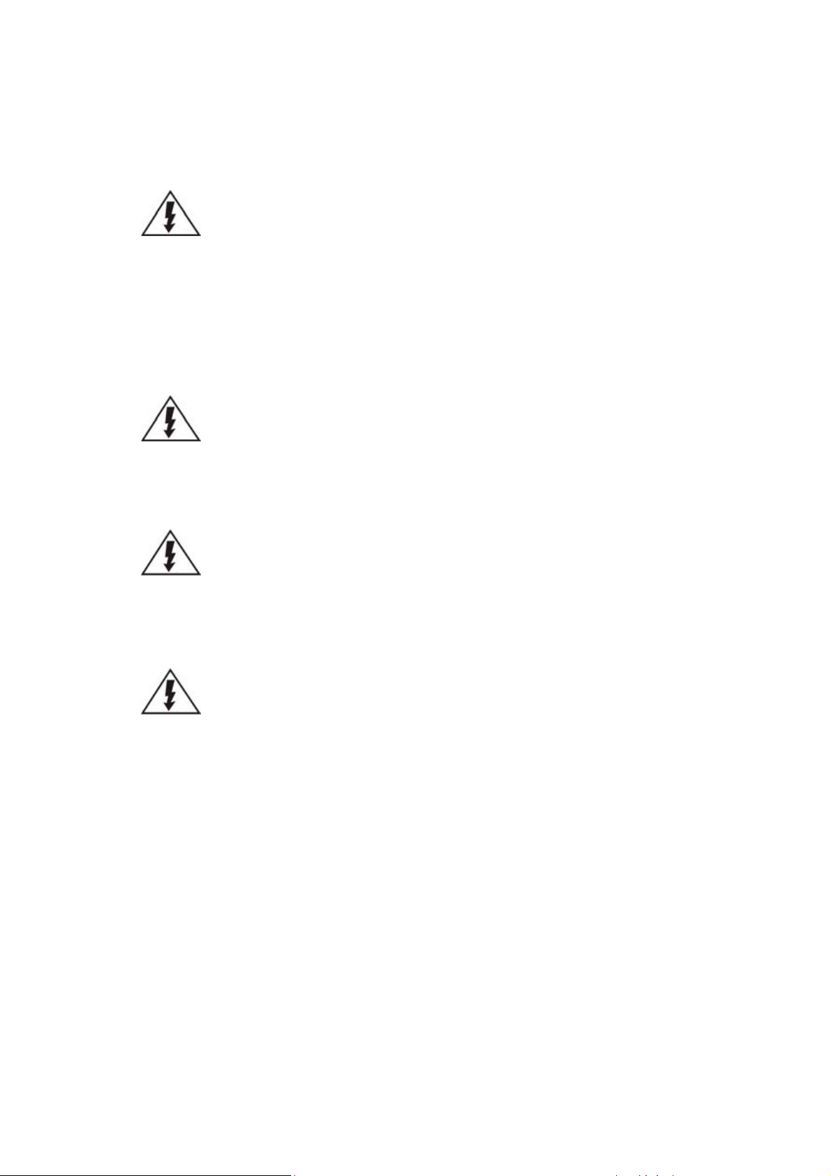
Function
1. Drive Trays
Holds 3.5” HDDs
2. LED Panel
Indicates the system status, including Service / Power /
Cooling Fan / Thermal / System LEDs.
3. Handle
To pull / push the enclosure out and into the cabinet when
the enclosure is installed on a slide rail rackmount system.
4. Power Button
Powers up the system.
5. Mute Button
Mutes an alarm when sound or indicates to the
administrator the system requires service.
1
3
2
3
4
5
Chapter 2. Hardware Overview
2.1. Front Panel
NVR7316
Page 26
26
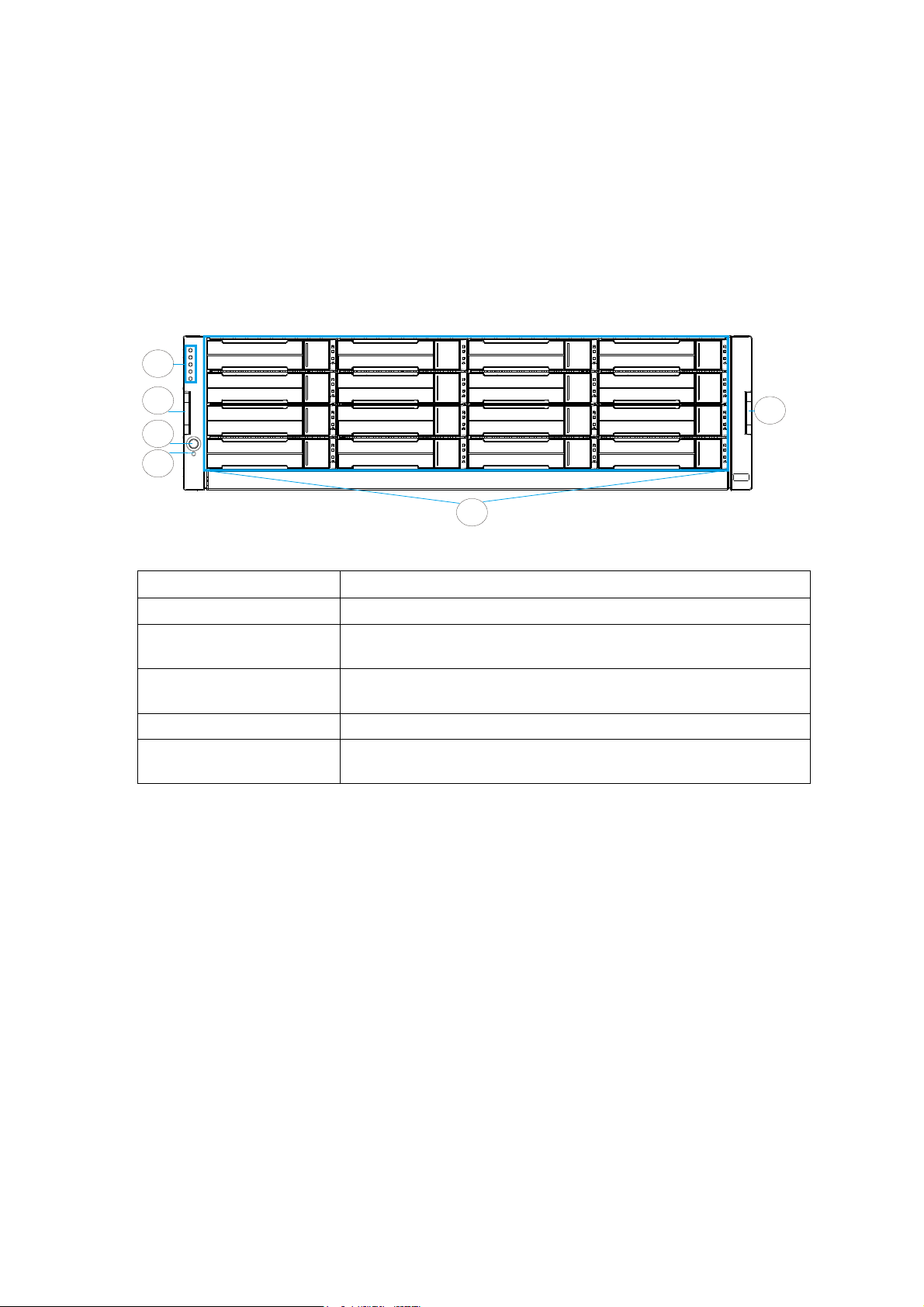
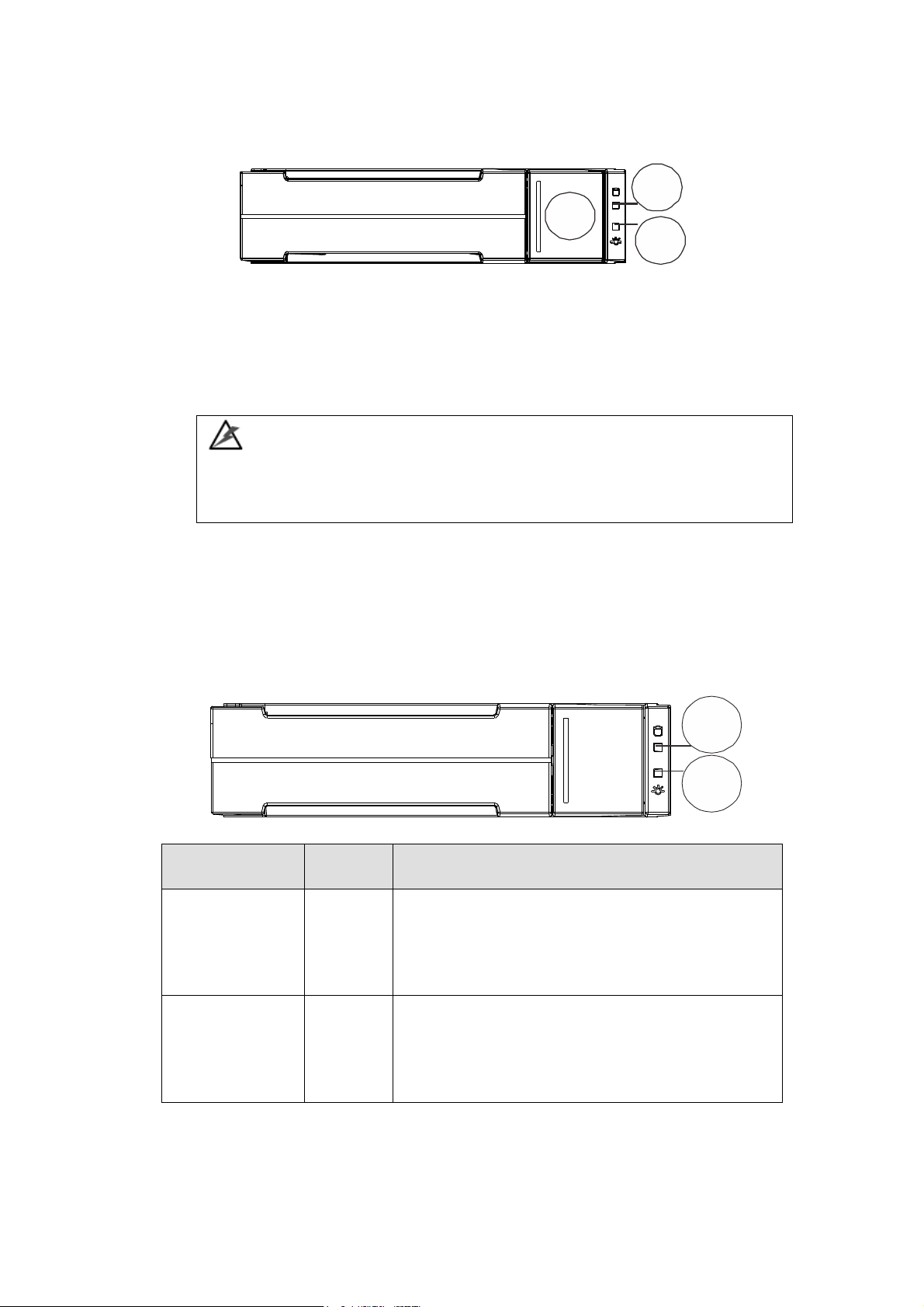
2
12
Function
1. Controller
The controller module represents the server component
of the system that contains a main circuit board with
various output and connections at the rear.
2. Power supply unit &
cooling module
The hot-swappable PSUs provide power to the system.
There is a cooling module within each PSU.
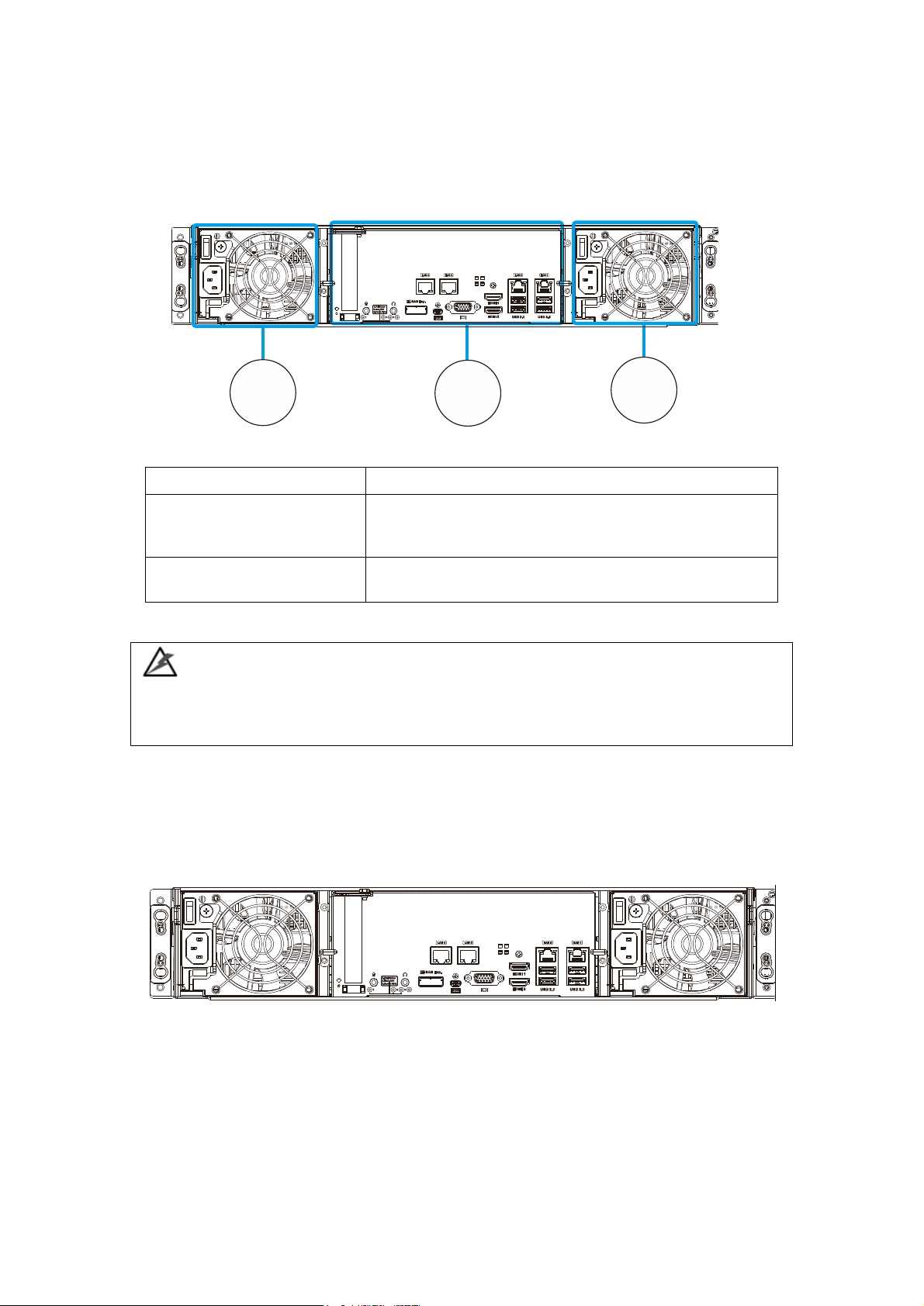
2U System
2.2. Rear Panel
NVR7316 Series
WARNING
Do NOT remove the non-redundant components!
Do NOT remove redundant components without a replacement on hand!
Main components are the rear side of the system consists of two power
supplies at the two ends with a controller in the middle.
Page 27
27
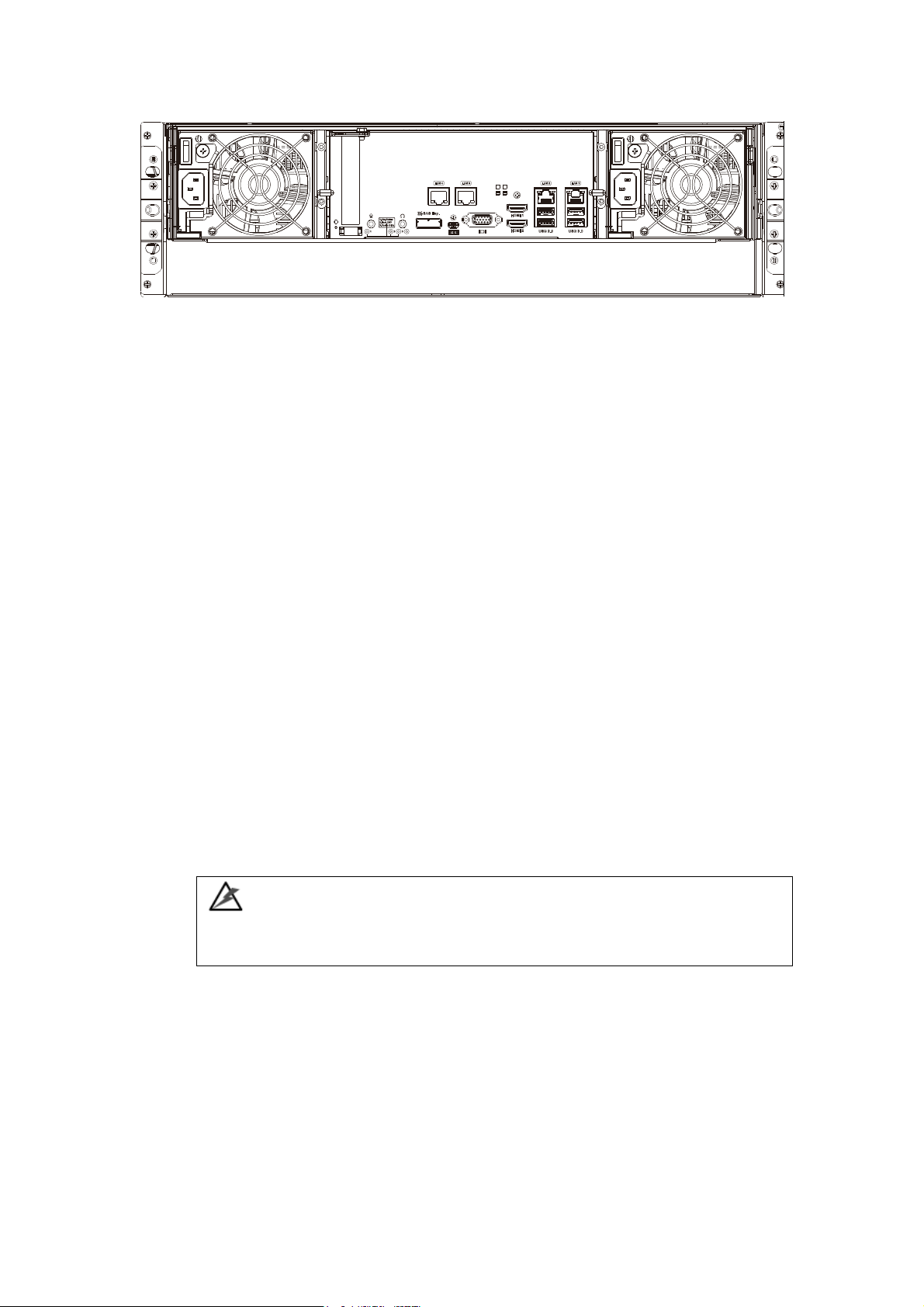
3U System
Connection between RAID and JBOD
The following rule applies when connecting RAID and JBOD(s):
2U systems connect to 2U JBODs.
3U systems connect to 3U JBODs.
Chassis
The RAID chassis is a rugged storage chassis divided into front and rear sections.
The chassis is designed to be installed into a rack or cabinet.
Internal Backplane
An integrated backplane separates the front and rear sections of the chassis.
This circuit board provides logic level signals and low voltage power paths.
Thermal sensors and I2C devices are embedded to detect system temperatures
and PSU/cooling module operating status. This board contains no user-
serviceable components.
WARNING
Accessing the backplane board may lead to fatal damage of the system. Also,
physical contact with the backplane board may cause electrical hazards.
Page 28
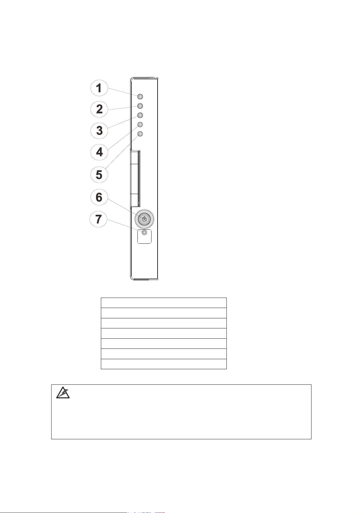
28
1. Service LED
2. Power supply status LED
3. Cooling module status LED
4. Temperature sensor status LED
5. System fault LED
6. Power button
7. Mute service button
2.3. LED Panel & Status
LED Panel
The LED panel can be located on the chassis ear.
WARNING
If critical faults are indicated on the LED panel, verify the cause of the problem as
soon as possible and contact your system vendor and arrange for a replacement
module.
Page 29

29
Name
Color
Status
1. Service
White
White indicates that the system is being serviced
or is requiring services.
OFF indicates that the system is not being
serviced nor is requiring services.
2. Power
Green/
Amber
Green indicates that the system is powered
properly.
Amber indicates that there is a power failure in
the system.
3. Cooling fan
Green/
Amber
Green indicates that the cooling fan is operating
properly.
Amber indicates that the there is a cooling fan
failure in the system.
4. Thermal
Green/
Amber
Green indicates that the internal temperature is
within the safety threshold.
Amber indicates that the internal temperature
has gone over the safety threshold.
5. System fault
Green/
Amber
Green indicates that the system is operating
normally.
Amber indicates that the system has
encountered abnormal conditions:
6. Power
button
N/A
Press and release instantly to turn on the
system.
To force system to shutdown, press and hold till
system shuts down!
Note: Some systems’ power button is located at
the rear.
7. Mute/
service button
N/A
Press the button once mutes the audible alarm.
Press and hold for more than two seconds to
mute the alarm and activates the service LED.
Page 30
30
Name
Color
Status
1. Drive Busy
Blue
Flashing Blue indicates data is being written to or
read from the drive. The drive is busy.
Steady Blue indicates that a hard drive is plugged-in
but there is no activity on the disk drive.
2. Power Status
Green /
Red
Green indicates that the drive bay is populated and
is working normally.
RED indicates that the disk drive has failed, or a
connection problem occurred.
1
2
3
1
2
2.4. Drive Tray Bezel
The drive tray is designed to accommodate separately purchased SAS or SATA
interface hard disk drives. There is a release button (1) that can be used when
retrieving disk drives from the chassis. To the right of the bezel plate, there is a
drive busy LED (2) and a power status LED (3).
WARNING
Be careful not to warp, twist, or contort the drive tray in any way (e.g., by
dropping it or resting heavy objects on it). If the drive bay structure is deformed
or altered, the drive trays may not fit into the drive bay.
Drive Tray LED
Two LED indicators are located on the right side of each drive tray. When
notified by a drive failure message, you should check the drive tray indicators to
find the correct location of the failed drive.
Page 31

31
Type I
Type II
2.5. Controller
2.5.1. Controller Type
There are two types of controller panels. The main difference is the LEDs. Type
II controller will be used for illustration purposes.
Page 32

32
12
11
9
10
8
7
2
6
3
4
5
1
12
14
16
13
15 17
1. Reset to default button and LED
10. HDMI port (Video only, Res: 1920
x1080@60Hz)
2. PCI-E expansion slot
11. USB 2.0 port
3. Controller status LED
12. USB 3.0 port
4. Host Busy LED
13. 3.5mm microphone jack
5. Cache Dirty LED
14. 3.5mm headphone jack
6. Reserved LEDs
15. 1 Gb/s Ethernet
7. 6Gb/s SAS expansion port
16. 1 Gb/s Ethernet (Wake On LAN)
8. miniUSB COM port
17. 1 Gb/s Ethernet
9. D-Sub VGA port
(Res: 1920 x1080@60Hz)
2.5.2. Controller Connections
Note:
The management port supports only 100Mbs and 1000Mbs (1Gbs) speeds.
PCI-E card is an optional add-on component!
WARNING
The only time you should remove the controller is to install/ replace the failed
controller. The RAID controller is built of sensitive components and unnecessary
tampering may damage the controller.
Page 33

33
1 2 3
Name
Color
Status
1.Ctrl Status
LED
Green/
Amber
Green indicates that a RAID controller is operating
healthily.
Amber indicates that a component failure has
occurred, or inappropriate RAID configurations
have caused system faults. It is also lit during the
initialization process.
2. Host
Busy
Green
Blinking Green to indicate traffic on the host bus.
3.Cache
Dirty LED
Amber
Amber indicates the following:
- Cache Memory is dirty.
- Errors occurred with cache memory (ECC
errors).
- Battery voltage is lower than 2.5V.
- Battery temperature reading is abnormal (out of
the 0 to 45°C range).
- Battery is not present.
OFF indicates that the cache is clean, and that the
battery backup unit is capable of sustaining
memory in case of power loss.
2.5.3. Controller LED
Page 34

34
Name
Status
Status
1. Speed
status LED
Green
Green indicates 1Gb connection established.
Off
Off indicates 10/100Mb connection established or
no connection established.
2. Link /
activity
Amber
Steady amber indicates a connection has been
established.
Flashing amber indicates data I/O.
Off indicates connection not established.
1
2
2.5.4. Ethernet Port LEDs
Page 35

35
1
2
3
4
5
6
2.6. PSU & Cooling Module
The two redundant, hot-swappable PSU have a power socket (1), power switch (2),
PSU status LED (3), cooling module (4), retention screw (5) and an extraction
handle (6).
The cooling modules can operate at three rotation speed settings. Under normal
operating conditions, the cooling fans run at the low speed. Under the following
conditions, cooling fans raise their rotation speed to increase the airflow:
Component failure: if a cooling module, PSU, or a temperature
Elevated temperature: if the temperature breaches the upper
During the system initialization stage, the cooling fans operate
NOTE
There are two upper temperature thresholds: one for event notification and the
other for triggering higher fan rotation speed. The preset-value for event
notification can be changed using the firmware-embedded configuration utility,
while the fan speed trigger cannot be changed. Refer to the Firmware Operation
Manual for details.
sensor fails.
threshold set for any of the interior temperature sensors.
at high speed and return to low speed once the initialization
process has completed and no erroneous condition detected.
Page 36

36
Status
Description
Flashing (Green)
The system is connected to power supply but the power switch has
not turned on.
On (Green)
The PSU / cooling module is operating normally.
On (Red)
The PSU / cooling module is faulty.
PSU/Cooling Module LEDs
The PSU (Power Supply Unit) contains the LEDs for the PSU and the cooling
module statuses. When either of the unit fails, you need to replace the PSU as
soon as possible.
PSU & Cooling Module Status LED
Page 37

37
2.7. System Monitoring Features
There are a number of monitoring approaches that provide the operating status of
individual components.
l2C Bus
The detection circuitry and temperature sensors are interfaced through a non-
user-serviceable I2C bus. When JBODs are attached to RAID controllers, JBOD
component status is reported through in-band protocols over expansion links that
is managed by a proprietary enclosure service.
The operating status of PSU and cooling fan modules are collected through an I2C
serial bus. If either of those modules fails, the failure will be detected and you
will be notified through the same methods as in the audible alarms.
Audible Alarms
If any of the following components fails, the audible alarm will be triggered:
Cooling fan modules
PSU modules
Hard disk drives
Sensors or presence detection circuitries
If the system administrator hears an alarm, the manager must read the error
message on the terminal or software screen to determine what has triggered the
alarm, and then take appropriate actions to rectify the problem. The alarm can
be turned off using the mute button on the front panel and the Alarm beep
pattern is described in the Troubleshooting Guide included in the CD-ROM.
NOTE
When temperature exceeds a preset threshold, the controller’s charger circuits
will stop charging. You will then receive a message that reads “Thermal
Shutdown/Enter Sleep Mode.” When the temperature falls back within normal
range, the battery will resume charging.
Page 38

38
2.8. Expansion Enclosure Support
Monitoring:
A managing RAID system is aware of the status of JBOD components including
those of:
Expander controller (presence, voltage and thermal readings)
PSU
Cooling module
Enclosure thermal sensor
Service (the Service signal to specify a specific enclosure)
Disk drives
JBOD Identifier:
The managing system will sound the alarm and deliver warning messages if there
is a conflict between JBOD IDs.
If more than one JBOD is connected to the managing RAID system, each JBOD
needs a unique enclosure ID set using the rotary switch on the LED panel. For
example, the firmware automatically disconnects the second JBOD if it is
connected online and comes with an ID identical to that of the first JBOD.
NOTE
The IDs for JBODs are #1 to #15. For details, please refer to JBOD connections.
Cooling Module Speed Adjustment:
If any of the detected temperature readings breaches the temperature
threshold, the firmware running on the managing RAID system automatically
raises the rotation speed of all cooling fans.
JBOD Enclosure Status Monitoring:
When connected with expansion JBODs, acquires the component status within
other enclosures via a proprietary enclosure monitoring service using the in-band
connectivity. No additional management connection is required.
Page 39

39
Hot-Swapping
The system comes with a number of hot-swappable components that can be
exchanged while the system is still online without affecting the operational
integrity. These components should only be removed from the system when they
are being replaced.
The following components can be user-maintained and hot-swappable:
PSU (including cooling modules)
Hard drive
NOTE
Normalized airflow ensures sufficient cooling of the system and is only
attained when all components are properly installed. Therefore, a failed
component should only be removed when a replacement is available. For
instructions on how to replace these hot-swappable components, please
refer to System Maintenance.
Page 40

40
Chapter 3. Software Overview
3.1. Software Introduction
Video Management Software (VMS) is a highly modular and powerful video and
hardware management suite that incorporates Server recording, management, and
video monitoring and playback functionalities to serve the core purposes of a video
surveillance system.
It operates in a client-server mode: The Local Client and Local Domain Server run
for standalone SMR/NVR/VMS Server, while the Remote Client receives live video
streams and event video playbacks from LAN or Internet. All administrative tasks
are performed on the Client. The client software provides the ability to monitoring
and playback recorded videos from multiple cameras. And for users having multiple
SMR/NVR/VMS Servers, Surveon Control Center (SCC) (its main functions are the
same with the VMS) can be utilized to manage over the domain infrastructure.
Page 41

41
3.2. Module Framework
VMS/NVR Server
Combines video recording, archival and retrieval functionalities for
individual servers/standalone PCs.
Serves as the connection point for client stations.
Local Domain Server
The interface between the VMS/VI Servers and any clients.
User authentication server.
Local Client
Local access, VMS Client installed on standalone PCs/NVRs for live video
monitoring, event recording playback access and VMS system
configuration.
Remote Client (full functions)
Remote access, VMS Client installed on remote PCs for live video
monitoring, event recording playback access.
Serves as the default configuration point for NVR2000 series, which do
not have a Local Client.
Web Client (for simple use)
Remote access, an ActiveX application (OCX) installed on remote PCs
for live viewing and event playbacks through the web browser.
SPhone Client (for simple use)
SPhone Client installed on iOS/ Android devices for basic live viewing.
Web Server
Allows user to access the live video stream, PTZ control and event
recording playbacks through Microsoft Internet Explorer 7.0 (or higher)
after the Web Clients components are downloaded.
VI Server
The video intelligence processing point for a VMS solution.
Preinstalled on SMR/NVR Server, and optional on a separate server/PC
(VMS).
SCC Domain Server
Allows centralized control over multiple Trusted VMS Server points and
connections from multiple clients.
SCC Client
Page 42

42
VMS Server + Client
Support NVRs
≥ 32CH
16~32CH
≤ 16CH
OS
64-bit :
Windows 7 Professional, Enterprise, Ultimate
CPU
Intel Core i7‐980X or
above
Intel Core i7‐860
or above
Intel Core i5‐650
or above
Memory
4 GB or above
Display
nVidia GeForce GTX660 2GB or above
Hard Drive
SATA 7200 RPM, 500 GB or above
Network
1 Gbps or above
Remote Client
OS
64-bit :
Windows 7 Professional, Enterprise, Ultimate
CPU
Intel Core i7‐980X
or above
Intel Core i7‐860
or above
Intel Core i5‐650
or above
Memory
4 GB or above
Display
nVidia GeForce GTX660 2GB or above
Hard Drive
SATA 7200 RPM, 500 GB or above
Network
1 Gbps or above
VMS Server Only
OS
64-bit :
Windows 7 Professional, Enterprise, Ultimate
CPU
Intel Core i3‐530 or above
Memory
4 GB or above
Display
On board (generic) 256MB or above
Hard Drive
SATA 7200 RPM, 500 GB or above
Network
1 Gbps or above
Software capable of accessing multiple Trusted VMS Servers through the
SCC Domain Server
3.3. System Architecture
VMS operates in scalable client - server architecture. This architecture can be
divided into three types: (1) Standalone Server (2) Standalone Server + Remote
Client (Web Client/SPhone Client) (3) Multiple Servers + SCC Client.
These are the hardware requirements for using PCs as Server or Client.
Page 43

43
3.3.1. Standalone Server (Client-Server All-in-One)
For users with standalone Server, the Local Client UI is used to manage NVR
Server services:
Application:
The Server, IP cameras are all in the same LAN.
Use NVR as Server
No installation needed.
Use PC as Server
Install both the VMS/NVR Server and VMS Client on a PC:
Insert the VMS/IPCAM product CD. Click VMS Suite on the menu to start
the installation. Choose Typical Setup. If you don’t need video analytic
functions, Advanced Setup can be selected to uncheck the VI Server.
Page 44

44
3.3.2. Standalone Server + Remote Client (Web
Client / SPhone Client)
For remote users to connect to SMR/NVR Server, a remote access, VMS Client
installed on remote PCs is needed for live video monitoring, event recording
playback access.
Also, the Web Client, an ActiveX application (OCX) can be used for basic live
viewing and event playbacks through the web browser, while SPhone Client can
be used for basic live viewing on iPhone/Android devices.
Application1: Internet
The Server, IP cameras and the PC/Mobiles are all in the same LAN.
Page 45

45
[NVR Server]
Use SMR/NVR as Server
No installation needed.
Use PC as Server
Install the VMS/NVR Server on a PC:
Insert the VMS/IPCAM product CD.
Click VMS Suite on the menu to start the installation.
Choose Advanced Setup to uncheck the VMS Client.
If you don’t need video analytic functions, the VI Server can also be
unchecked.
Install the Web Server on the PC:
Insert the VMS/IPCAM product CD.
Click Browse CD/DVD in the menu.
Double click WebServerSetup.exe to start the installation.
[Client]
Install the VMS Client on PCs:
Insert the NVR/SMR product CD.
Click VMS Client on the menu to start the installation.
Install the Web Client on the PCs (Optional):
Launch Microsoft Internet Explorer 7.0 (or above) and enter your VMS Server IP
address + “/webclient” in your web browser’s URL location, eg.
http://172.18.6.9/webclient to download the Web Client application.
Install the SPhone Client (Optional):
Download the SPhone Client from App Store on the iPhone desktop.
Install the SPhone Client (Optional)
Download the SPhone Client from App Store on the Andriod phone desktop.
Note: Please refer to Installing the VMS and Installing the Web Client for details.
Page 46

46
Application 2: Internet
The Server, some of the IP cameras and the PC are all in the same LAN, while the
other IP cameras are installed in remote location with Public IP.
3.3.3. Multiple Servers + SCC Client
For users with multiple SMR/NVR Servers, SCC Client UI is used to manage over
the domain infrastructure.
Page 47

47
CMS Client
NVR
Server
VI Server
CMS Domain Server
CMS Client
Multiple Servers + CMS Client
NVR
Server
NVR
Server
Application3: Internet
(1) The Servers, IP cameras and the PCs are in LAN A.
(2) Some IP cameras are installed in LAN B, which is behind a different outer
in a remote location.
(3) Users are allowed to connect the SMRs/NVRs from remote PC over the
Internet.
[NVR Server]
Use SMR/NVR as Server
No installation needed.
Use PC as Server
Install the VMS/NVR Servers on PCs:
Insert the VMS/IPCAM product CD.
Click VMS Suite on the menu to start the installation.
Choose Advanced Setup to uncheck the VMS Client.
The VI Server can also be unchecked, if you don’t need video analytic functions.
[VI Server] (Optional)
You can choose to install the VI Server only on a standalone PC to manage the
video intelligence data.
Insert the VMS/IPCAM product CD.
Page 48

48
Click VMS Suite on the menu to start the installation.
Choose Advanced Setup to choose VI Server only.
[SCC Domain Server]
Install the SCC Domain Server on a PC:
Insert the NVR/SMR product CD.
Click SCC Suite on the menu to start the installation.
Choose Advanced Setup to select the SCC Domain Server only.
[SCC Client]
Install the SCC Client on PCs:
Insert the NVR/SMR product CD.
Click SCC Suite on the menu to start the installation.
Choose Advanced Setup to select the SCC Client only.
Note:
(1) For users don’t have Surveon SMR/NVR series, please contact your dealer for the
SCC installation file.
(2) The SCC Domain Server can also be installed together with the SCC Client in the
same PC by choosing Typical Setup.
(3) Please refer to Installing the VMS and Installing the SCC for details.
Page 49

49
Access through a firewall
Use port forwarding to access
SMTP (25),
HTTP (80),
FTP (20, 21),
OMNI (2809),
HTTPS (443),
RTSP (554, 8554.)
Stream Port (9090),
Doman Data Port (9060),
Log Download Message Port (15507),
Log Download Data Port (9080)
3.3.4. Network Requirements
In order to preserve enough bandwidth for surveillance video, a surveillance
network is presumed to be free of user/business traffic. Server software currently
supports Class B and Class C type addresses. Currently the Server software only
searches for Servers on the same subnet. Cameras should also reside on the same
subnet.
Opening Ports
If access through a firewall in a local network is required, try opening the following
ports: SMTP (25), HTTP (80), FTP (20, 21), OMNI (2809), HTTPS (443) and RTSP
(554, 8554.). Other ports should also be opened while using port forwarding to
access the VMS Server: Stream Port (9090), Doman Data Port (9060), Log Download
Message Port (15507) and Log Download Data Port (9080).
Note: Please refer to Port Forwarding Section for more details.
Warnings / Precautions
If the Server and a VMS client reside on separate subnets, please set up gateway,
VLAN, or cross-subnet routing to bridge surveillance traffic. Please consult with a
network administrator for problems with network setups. A VMS client needs to be
rebooted when network settings are changed.
Page 50

50
3.4. Port Forwarding
Port forwarding is a name given to the combined technique of:
1. Translating the address and/or port number of a packet to a new destination.
2. Possibly accepting such packet(s) in a packet filter (firewall).
3. Forwarding the packet according to the routing table.
To illustrate its concept, two computers on the Internet that communicate with each
other using TCP/IP or UDP/IP protocols(though the process is not limited to these)
utilize ports to identify the opposite connection points of each other where the data
packets supposed to go to. In order to communicate, each computer knows the port of
another computer (in addition to IP address) and sends the data to that port. Port
forwarding forwards these ports in such a way that when one computer sends data to
the specific port of another computer, the data is actually sent to a different port.
This allows remote computers to connect to a specific computer or service within a
private LAN.
In a typical residential network, nodes obtain Internet access through a DSL or cable
modem connected to a router or network address translator (NAT/NAPT). Hosts on the
private network are connected to an Ethernet switch or communicate via a wireless
LAN. The NAT device's external interface is configured with a public IP address. The
computers behind the router, on the other hand, are invisible to hosts on the Internet
as they each communicate only with a private IP address.
When configuring port forwarding, the network administrator sets aside one port
number on the gateway for the exclusive use of communicating with a service in the
private network, located on a specific host. External hosts must know this port number
and the address of the gateway to communicate with the network-internal service.
When used on gateway devices, a port forward may be implemented with a single rule
to translate the destination address and port. The source address and port are, in this
case, left unchanged. When used on machines that are not the default gateway of the
network, the source address must be changed to be the address of the translating
machine, or packets will bypass the translator and the connection will fail.
Page 51

51
3.4.1. Port Forwarding for Accessing VMS Server
To enable port forwarding for accessing VMS Server, please follow the steps below:
1. Do Router Port Mapping for VMS/NVR Server
Go to VMS Setup > Network > Port Mapping in VMS after it is installed.
Page 52

52
Port(Host/Global Port)
Protocol
Port Number
Domain Message Port
UDP
9050
Domain Data Port
TCP
9060
Login Port
TCP
2809
Stream Port
TCP
9090
Log Download Message Port
TCP
15507
A Router Port Mapping window will prompt for entering port numbers. Please put
in the numbers as listed below:
Stream Port: 9090
Login: Port: 2809
Doman Data Port: 9060
Log Download Message Port: 15507
Log Download Data Port: 9080
2. Open Ports on the Router
Host Ports: The private ports that the internal VMS/NVR Server use, which are
unchangeable.
Global Ports: The public ports for remote clients to connect to the internal
VMS/NVR Server. The Global ports are changeable, but the simplest way is to make
them the same with the host ports.
Please open the listed ports on your router:
(When the option “Enable Automatic UPnP Mapping” is selected, this step can be
skipped.)
Page 53

53
Log Download Data Port
TCP
9080
Note: Camera port (default: 80) and stream port (default: 6002) for accessing
cameras should be opened while VMS/NVR Server and the cameras and are not
in the same LAN.
Page 54

54
Network Video
Recorder
NVR7300 series
IP Camera
Network Cameras (such as CAM2441)
Network
Existing LAN, Switch, Router or Hub
(please see the Network Topology below)
Storage
Hard Drives
Common Topology
Reference Product
Existing LAN
LAN Switch with DHCP Server
Office LAN
Router
LAN Switch with build-in DHCP Server
D-Link DIR-130
Switch/Hub
No DHCP Server(refer to the Note below)
D-Link DES-1108
Chapter 4. Installation
4.1. Before You Start
4.1.1. Checklist for Operating Environment
Users need to prepare the following devices to set up the surveillance system.
Note: The hard drives should be purchased separately.
4.1.2. Checklist for Network Topology
Make sure you have the right switch/hub for your environment. Either of the
following options will work.
Note: For devices without DHCP Server function, please refer to Configuring DHCP
Service Section.
Page 55

55
Item
Description
Quantity
01
Mounting bracket assembly, left-side
1
02
Mounting bracket assembly, right-side
1
03
Inner glides
2
04
Flathead screws #6-32 L4
6
05
Truss head screws M5 x9.0mm
8
06
M5 cage nuts
4
07
M5 x 25mm
4
08
M6 x 25mm
4
09
#10-32 x 25.4mm
4
5
2
3
4
6
7
8
1
9
4.2. Slide Installation
4.2.1. Slide Rail Kit Contents
The following table shows all accessories that came with the slide rail kit.
Page 56

56
M5 x 9.0mm
05
M5 x 9.0mm05
Inner glide rail
#6-3208
4.2.2. Installation Procedure
1. Determine the exact position for enclosure installation (front and rear rack
posts).
2. Refer to the illustration below to insert cage nuts into the front rack post
and truss head screws to secure the slide rail.
3. Adjust the length by loosening the four screws on the slide rail. Secure the
slide rails to front and rear posts using truss head screws (05) and tighten
the four screws on the slide to fix the length.
4. Attach the inner glides to BOTH sides of the enclosure using flathead screws
#6-32 (04).
5. With the assistance of another person, lift and insert the enclosure onto the
slide rail.
Page 57

57
UNLOCK U NLOCK U NLOCK
6. Make sure the inner glides on both sides of the enclosure meets the inner
glide rail. Secure the enclosure using M5 or M6 screws from the front.
Page 58

58
4.3. Hard Drives Installation
Hard disk drives are purchased separately. When selecting hard disk drives (HDD), HDD
manufacturers always urge users to choose enterprise/surveillance grade drives for
24/7 surveillance operations to ensure system stability. The surveillance hard drives
on our Approved Vendor List (AVL) are engineered to work continuously, withstand
high-temperature fluctuations and equipment vibrations found in any typical
surveillance application. To reduce errors occurred on your RAID data and the chance
of the recording performance being affected, it is highly recommended to use HDDs
listed on our Approved Vendor List (AVL) to ensure reliability. Find the AVL on our web
page: http://www.surveon.com/support/hardware.asp
4.3.1. Prerequisites
Hard drives are separately purchased and when purchasing hard drives, the
following factors should be considered:
Capacity (MB/GB): Use hard drives that have the same capacity and rotation speeds.
RAID arrays use a “least-common-denominator” approach meaning the maximum
capacity used in each drive for comprising a logical configuration is the maximum
capacity of the smallest drive.
Drive Interface Type: The enclosure accommodates SATA-II or SATA-III hard drives.
Note: The hard drives and drive trays should only be installed into the system after it
has been mounted into a rack cabinet. If the hard drives are installed first, the
system will be too heavy to handle and the possible impact during installation
may damage your hard drives.
Users MUST install at least ONE hard drive into slot 1 to setup the system. It is
strongly recommended to install at least TWO hard drives upon initialization!
Page 59

59
RAID Level
Max. No. of Failed Drives without Data Loss
0
No fault tolerance. 1 drive fails and the data is lost.
1
1 (mirrored pair)
5 1 6
2
RAID Configuration: Below is a list of the level of fault tolerance for different RAID
levels:
Hard drive for storage: It is recommended to use hard drives that are of the same
brand, capacity, rotation speed and same model in an enclosure. RAID arrays use a
“least-common-denominator” approach meaning the maximum capacity used in
each drive for comprising a logical configuration is the maximum capacity of the
smallest drive.
Note: Hard drives dedicated for OS will have certain storage capacities that are
unavailable for use towards the total storage capacity.
WARNING
Make sure all enclosure tray slots are filled a hard drive tray (with or with a hard drive) as an
empty tray slot may affect the airflow efficiency of the enclosure!
The hard drives should only be installed into the system AFTER the enclosure has been rack
mounted as the combined weight will be too heavy to handle.
Handle hard drives with extreme care and observe all ESD prevention methods when installing
drives.
Only use screws supplied with the system package. Longer screws may damage the hard drives
or its trays.
Page 60

60
1 2 3
4
5 6 7 8 9
10
11
12
2U systems
1 2 3 4 5 6 7
8
9
10
11
12
13
14
15
16
3U systems
Hard Drive
Slot 1
Hard Drive
Slot 2
Hard Drive
Slot 3
Hard Drive
Slot 4
Hard Drive
Slot 5
Hard Drive
Slot 6
Hard Drive
Slot 7
Hard Drive
Slot 8
Hard Drive
Slot 9
Hard Drive
Slot 10
Hard Drive
Slot 11
Hard Drive
Slot 12
Hard Drive
Slot 13
Hard Drive
Slot 14
Hard Drive
Slot 15
Hard Drive
Slot 16
4.3.2. Hard drive Designation
Illustrations shown below are system hard drive slot number designations. Please
familiarize yourself with the designations to avoid withdrawing the hard drive(s) out
of the enclosure.
The general alignment is from left to right and/ or top to bottom in numeric order
as shown below.
Page 61

61
Note: At least four (4) hard drives must be installed for RAID 5 or five (5) hard drives
must be installed for RAID 6 to create an initial volume!
4.3.3. Replacing a Hard Drive
Installing 3.5” HDD
Removing the HDD tray
Press the release button to open the bezel and gently pull the HDD tray out of the
enclosure.
Attaching the HDD
The interface connector should face the open side of the tray, while the label side
should face up.
Secure the drive by fastening four (4) of the supplied screws.
Page 62

62
3.5”
2.5”
Front
Inserting and securing HDD tray
Insert with tray bezel open.
Once the hard drives have been installed in the drive trays, the drive trays are ready
to be installed into the system.
With the tray bezel open, insert the installed hard drive and tray into the
enclosure. Once inserted, close the tray bezel.
Page 63

63
4.4. Other Components Installation
4.4.1. Installing PCIe Card (Optional)
To install the PCI-E card, you need to remove the controller. Please confirm with
support personnel on PCI-E card qualification before purchase / installation!
1. Loosen the screws and remove the covers shown in the illustration below.
2. Install the PCI-E card into PCI-E slot. Secure it with the cover and screws.
PCI-E 3.0 x 8 (optional)
3. Insert the controller back into the enclosure. Secure the screws
underneath both levers.
Page 64

64
4.4.2. Replacing the Power Supply Module / Cooling
Module
The power supply units (PSU) are configured in a redundant configuration with each
PSU housed in a robust steel canister.
4.4.3. Detecting a Failed PSU
If a PSU module fails, the system notifies you through the following indicators:
PSU status LED locations
Audible alarm
Firmware utility (refer to Firmware User Manual in the CD-ROM for
details)
4.4.4. Replacing Power Supply Unit
A failed PSU should be replaced as soon as possible, but only when you have a
replacement module in your hand. Contact your vendor for more details.
WARNING
Although the system can operate with a failed PSU in a system, it is not
recommended to run the system with a failed PSU for an extended period of
time. The failed spare redundant PSU should be replaced as soon as possible!
To replace a PSU, follow these steps:
1. Power off the system, turn off the PSU and unplug the power cord.
Page 65

65
2. Loosen the retention screw that secures the extraction handle to the
chassis.
3. To remove the PSU module, pull the extraction handle downwards to
disconnect the PSU from the backplane connectors. Once dislodged, gently
pull the PSU out of the system. If the system is mounted in a rackmount
rack, use another hand to support its weight while removing the module.
Page 66

66
4. Insert the replacement module. Make sure the extraction handle is
pointing outwards. Push the replacement PSU into the chassis, and when
you feel the contact resistance, push the extraction handle towards the
PSU module and it should engage the back-end connectors.
5. Fasten the thumb screw.
6. Reconnect the power cord.
7. Power on the PSU module.
Page 67

67
4.5. Connections & Expansions
4.5.1. System Connections for Initialization
Note: Make sure you have at least installed ONE hard drive into the system.
It is strongly recommended to install at least TWO hard drives upon
initialization!
The system connection requires the user to
(1) Connect an Ethernet cable from the system to a switch / router
(2) Place the CD that came with the system into your PC’s CD-ROM
(3) Connect an Ethernet cable from the “SAME” switch / router to the PC
(4) Connect the power cable(s) to the system and to a power outlet
(5) Press the power button / switches to start up the system
Page 68

68
4.5.2. SAS Interface
The SAS interface features a dual-ported connectivity with pins on both sides of its
connector that include SAS primary links (1), power link (2) and underneath it, the
SAS secondary links (3). The SATA drives have only one port that includes the SATA
physical links (4) and the power link (5). In a redundant-controller system, the MUX-
enabled drive trays must be separately purchased and applied. The single-controller
JBODs do not require MUX kit.
Dual-ported SAS and Single-port SATA Connectors
WARNING
The hard drives and drive trays should only be installed into the system after rack
mounting. If the hard drives are installed first, the system will be too heavy to handle
and the possible impact during installation may damage your hard drives.
Handle hard drives with extreme care and observe all ESD prevention methods when
installing drives.
Only use screws supplied with the system package. Longer screws may damage the
drive.
Page 69

69
4.5.3. Powering Up
Connecting the power cord
Connect the power cords to the power socket (in blue) on both PSUs.
Powering up the equipment
1. Power up the networking devices.
2. Power up the JBODs (if applied) by pressing the power switches on the rear panel.
3. Power up the system by switching on both power switches (shown above in green)
on the rear panel and press the power button on the front panel.
4. Power up the application servers.
Page 70

70
System LED: Green
Service LED: Off
Power LED: Green
Cooling fan LED: Green
Thermal LED: Green
4.5.4. Status LED When Powered-on
Verifying status LEDs (front of enclosure)
Observe the front of the enclosure. If the LED indicators show different status than
described below, or if you hear an audible alarm, please contact customer support.
Front panel LEDs:
Drive tray:
• Power Status LED: On (green)
Verifying the status LEDs (rear of enclosure)
Observe the rear of the enclosure. If the LED indicators show different status than
described below, or if you hear an audible alarm, please contact customer support.
PSU LED:
• PSU LED: On (green)
Page 71

71
4.5.5. Connecting JBOD
The following illustration is the recommended JBOD expansion connection; the
maximum of JBOD expansion connection is up to 3 sets.
Setting JBOD IDs
Use a small flat blade screwdriver to set the JBOD enclosure ID(s). A different ID
number must be allocated for each JBOD.
Configuring enclosure IDs:
The configurable IDs for JBODs are from 1 to 15. Usually the numbering starts
from the one closest to the managing RAID enclosure.
Make sure a unique ID is configured on each JBOD so that the SAS WWN addresses of
disk drives can be properly assigned. NVR7300 system firmware automatically
manages these addresses.
JBOD Expansion Connections
• EonServer SAS exp. – 1st JBOD SAS-IN
• 1st JBOD SAS-OUT – 2nd JBOD SAS-IN .. and so forth!
Page 72

72
1st JBOD
2nd JBOD
.
.
.
.
.
.
.
Last JBOD
Page 73

73
1
2
3
4
4
5
1
2
34 4
Controller Module of JBOD Models
The expansion JBOD controllers features SAS expansion ports (1), SAS expansion port
status LEDs (2), controller status LEDs (3), extraction levers and retention screws
(4) and convection holes* (5).
The expansion controller contains a circuit board within a metal canister, interfaced
through hot-swap docking connectors at the back-end. Two SAS wide ports on the
interface faceplate connect to a managing RAID system or other JBODs.
WARNING
The only time you should remove the controller is to replace a failed controller. The
controller is built of sensitive components and unnecessary tampering can damage the
controller.
Page 74

74
Name
Color
Status
1. SAS Link
Green
Steady green indicates all 4 PHYs are validly linked to
external devices.
Blinking green indicates one of the 4 PHYs links has
failed.
OFF indicates all 4 PHYs are offline.
2. SAS Speed
Green /
Amber
Green indicates 6Gbps link speed.
Amber indicates 3Gbps link speed.
OFF indicates no connection.
3. Ctrl Status
Green /
Amber
Green indicates the controller is operating normally.
Amber indicates a component failure has occurred. It
is also lit during the initialization process.
1
2
3
Controller LED for JBOD Models
Page 75

75
U S B 3 . 0
p or t s
U S B 2 . 0
po r ts
HD M I 1
HD M I 2
J B O D S A S
e x pa n s io n
D -S ub
V G A p o r t
E th e r ne t
po r ts ( o p t io n al )
E th e r ne t
po r ts
P C I e C a r d
S lo t (o p t ion a l)
4.5.6. Connecting Interfaces
Overview of connection interfaces
Page 76

76
4.6. Logging into NVR7300 Series
The Local Client will prompt for the following information after the NVR7300 Series
system is powered on:
Username: The username of the domain, which is always admin.
Password: The password of the domain. Default password is admin.
Auto Login: Check this option and you do not have to input the username and the
password again when logging in next time.
Click Login after the password is entered.
Page 77

77
4.7. Run the Install Wizard
When you run the NVR series for the first time, you need to go through the following
steps within the Install Wizard after logging in.
1. Welcome: Use the dropdown list to select the language for the VMS. Click “Next”
to go to the next step Confirm the number of your hard drives.
2. Confirm the number of your hard drives: the system will auto detect the
number of installed hard drives.
Check if the detection result is correct, if yes, click ”Yes and proceed” or
“Next” to go to the next step Recording plan.
If the detection result is not as expected, click ” No and shutdown”. Shutdown
the system and make sure all the drives are installed properly. After checking,
restart the system to run the install wizard.
Contact your system administrator, if this error keeps happening.
Page 78

78
RAID Level
RAID
Description
Min.
HDD
HDD Used
for Storage
Non-RAID
No protection, but maximum
capacity.
2
All of HDDs
RAID 1
Best protection. Your data will be
mirrored.
2
Half of HDDs
RAID 5
Use 1 disk to store the parity
function data to provide fault
tolerance.
3
HDD number
minus 1
RAID 6
Used 2 disks to store the parity
function data to provide fault
tolerance.
4
HDD number
minus 2
3. Recording plan: Select the best storage configuration for the system. See the
following table for reference.
Please seek for professional help, if you are not sure how to select the RAID level.
Page 79

79
Note: (1) Use EonOne Lite to setup RAID level configuration. (2) When setup RAID for
JBOD connections, please make sure to stop NVR recording firstly before
configuration.
(3-1) Default recording behavior: Select the best recording method. When Always
recording is selected, every image will be recorded. When Motion recording is
selected, only motion detected images will be recorded, and approximately
25~60% storage can be saved according to the levels of motion detection
sensitivities you have set.
Page 80

80
Click “Next” to go to the next step Time.
4. Time: Time setup should be done correctly; otherwise some of the functions will
be affected. Set up the time zone before setting up the time.
Note: Date/Time should be set correctly before recording.
(4-1) Time synchronization: There are options to choose from.
Time synchronization can be applied to all connected cameras.
You can also make this NVR as time server so that the time synchronization
Page 81

81
can be applied to all the connected devices.
You can have the time on the system to be synchronized with the NTP time
server.
Click “Next” to go to the next step Basic settings.
5. Basic Settings: You can change or use the default password. Check the “Use
Default Password” option, if you wish to keep the default password.
If you want to change the password, input a new password and confirm the newly
created password.
Note: The system will restart when the server name is changed.
Page 82

82
Click “Next” to go to the next step Network.
6. Network: Different network settings can be applied to 2 LANs if there are 2 LANs
on the system. It is recommended to select “Auto detect”, since the system will
detect if there is any DHCP server available. If yes, it will assign an IP address.
You also can select “Use fixed IP” to input the IP address of this NVR and make
this NVR as a DHCP server. After selecting, input the relevant information and
check “Enable DHCP service on this NVR” to confirm the setting.
Warning: Make sure that only 1 DHCP server is activated in your system,
otherwise it may cause network errors.
Note: You can also change the network settings, once you’re logged in to the
Local Client. Go to Setup > Network > DHCP Server for the network configuration.
Click “Next” to go to the next step Summary.
7. Summary: This page shows the setting results you have set so far. Check if the
results are what you wished for. If not, click on the items to go back the items
you wish to modify and set up again.
Page 83

83
After clicking “Next”, the wizard will start to initialize your system and go to the
next step Progressing.
If you wish to set up the local display, you can click this item and go to the Local
display page.
Local display: Select the best method for your scenario to have a balanced resource
usage for the quality of recording and local display.
Page 84

84
Note: The system will restart when the setting is changed.
8. Progressing: After clicking “Next” on the summary page, the wizard will start to
initialize your system. This act will take a few minutes to complete. Once it is
done, the system will reboot automatically.
9. All complete: All the necessary settings are done. Click “Finish” to close this
Page 85

85
window and the system will be directed to the VMS. You can modify and configure
more settings later in the setup page.
(9-1) Camera detection: The system will detect the cameras in the same LAN.
Click the detection result to go to the next step Add camera.
Click “Finish” to close this window. You can add cameras later in the setup page.
10. Add camera: The detected cameras will be shown here. Select the cameras you
wish to add and click “Add selected” to add the selected cameras.
Click “Rescan” to detect the cameras again.
Page 86

86
Click “Finish” to close this window. You can also add cameras later in the setup
page.
After the wizard installation is done, you will see the Live View page from the
Local Client.
Page 87

87
4.8. EonOne Lite
EonOne Lite: EonOne Lite is a browser-based Graphical User Interface (GUI) that
can to monitor and manage the system. For more details, please refer to EonStor
Lite Installation Manual.
(1) You are recommended to log in to your computer as an administer or the root
user before launching the installation / installation process.
(2) On the operating system of the host server, download the installation package
and unzip the downloaded file. In the extracted folder, double-click "setup.exe"
to launch the installation wizard.
(3) Click the EonOne Lite shortcut on your Desktop to launch the web-based EonOne
Lite interface, or go to either of the following addresses using a web browser:
HTTP access: http://127.0.0.1:8816/
HTTPS access: https://127.0.0.1:8817/
(4) When the login screen appears, enter the username and password, select or
deselect the checkboxes, and then click “LOGIN”. The default username and
password are “admin.”
(5) When the login process is complete, the overview page of EonOne Lite will
appear.
Page 88

88
(1) When you access EonOne Lite for the first time, a Start Quick Setup will show up
for configuring storage device guidance.
Step 1 Configuring new partition
You can see the front view and indicator lights of the storage device or JBODs (if
any) displaying the status of the device(s) and hard drives.
To the right of the front view, you can see the RAID level and the capacity of the
partition which is about to be created from the newly added storage device and
its connected JBODs (if any).
Step 2 Creating a partition
Click Apply to continue with the next step, which enables the system to create a
new partition based on the settings you configured in the previous step.
Step 3 Finishing Quick Setup
When the partition is created, you can do either of the following
Click Device Management to enter the management GUI of EonOne Lite.
Click Logout to leave EonOne Lite.
Page 89

89
Chapter 5. Basic System Settings
5.1. Storage Management
1. To access the information about the drives configured in your Server, click Setup
to bring out VMS Setup window and then select Record to see and click
Storage option for Storage Manager.
2. All available Logical Drives, as well as their sizes, free space, and status will
appear. Click target drive and then Setting to set the log and location for saving
the video recordings.
Page 90

90
3. Click the target drive first and then Settings. In “General” tab, click Check.
4. Choose the RAID level, and then click Create Logical Drive to create the RAID
configuration. The system supports recording to ISCSI and NAS.
5. In “IP Storage” tab, you can authenticate targets by clicking CHAP to setup CHAP.
Page 91

91
Add: Click Add and input the required information to add more targets.
Delete: Click Delete to delete the selected.
Refresh: Click Refresh to refresh.
Target: Click Targets to see the setup result.
6. In “NAS” tab, you can add NAS in as the video storage.
Click Add and input the required information to add NAS as the video storage.
Page 92

92
Page 93

93
5.2. Adding Cameras to the Server
Cameras can be added to the Server in two ways: via an automatic scan or by manually
inputting the camera information.
5.2.1. Automatic Scan for Cameras
Right-click on the “Default Group” area to bring out the setting menu and select
Scan For Camera.
1. The system will respond by beginning an automatic scan. Once the scan is
complete, the cameras that can be added to the Server will be displayed.
Information available for each camera will include:
Page 94

94
Name – The default camera name (Make/Model)
Status – The camera will display New if it has not been added to this
Server, otherwise it will display Assigned.
IP Address
MAC Address
Vendor - Including ACTI, Afreey, AXIS, Arecont, BOSCH, Dahua,
Dynacolor, EDIMAX, EverFocus, HIKVISION, IQinvision, JVC, LG,
Panasonic, Surveon, and ONVIF.
Model
2. To add a camera to the system, check the box by the camera entry. You may
also check the Select All box at the bottom of the window to select all the
cameras found. Enter the username and password, and press Apply Selected.
Click OK to add the selected cameras to the Server.
The following windows will prompt for validation.
Page 95

95
5.2.2. Manually Adding Cameras
1. Right-click on the “Default Group” area to bring out the setting menu and
select Add Camera to manually add a camera to the Server.
2. In the camera window, fill out the following information:
IP Address
Camera Port – This value will automatically populate with the default
value for the Vendor and Model selected.
Page 96

96
Vendor - Including Including ACTI, Afreey, AXIS, Arecont, BOSCH,
Dahua, Dynacolor, EDIMAX, EverFocus, HIKVISION, IQinvision, JVC,
LG, Panasonic, Surveon, and ONVIF.
Stream Port – This value will automatically populate with the default
value for the Vendor and Model selected.
User Name – This value is not always required.
Password – This value is not always required.
Camera Name – It is recommended you change this value if you have
more than one camera of this make/model.
Camera Icon – Select or change icon here.
Camera Description – Add more information here.
Page 97

97
5.3. Setting Recording Schedule
5.3.1. Recording Schedule
Click to bring out VMS Setup window and select Record and then Schedule.
1. The schedule grid corresponds to every hour in the week. Click on one of the
4 recording methods and then click on the grid area to “paint in” the method
for the corresponding hour.
Page 98

98
2. Click the Apply button to apply the schedule and OK to exit the dialog.
Page 99

99
5.4. Setting up Live View
An important part of monitoring your surveillance network is to have the right views so
that you will have the optimum viewing angle to discern a situation.
The default view setting is 4x4.
From the Camera List, you can click and drag each camera into separate frames.
The camera output will be displayed in the frame.
On the Main View Area, right click on one camera view. Select Others >> Remove
Camera to delete this camera view on the main frame.
Page 100

100
 Loading...