

Page 1

NVR2100 Series
User Manual
Release 1.3
Page 2

2
Revision History
Description
Date
1.0
Initial release
July 2013
1.1
FW2.5 upgraded
August 2013
1.2
UI Modified
November 2013
1.3
Remote Monitoring Modified
June 2014
Page 3

3
All Rights Reserved © Surveon Technology 2014
Copyright Statement
No part of this publication may be reproduced, transmitted, transcribed,
stored in a retrieval system, or translated into any language or computer
language, in any form or by any means, electronic, mechanical, magnetic,
optical, chemical, manual or otherwise, without the prior written consent of
Surveon Technology Inc.
Disclaimer
Surveon Technology makes no representations or warranties with respect to
the contents hereof and specifically disclaim any implied warranties of
merchantability or fitness for any particular purpose. Furthermore, Surveon
Technology reserves the right to revise this publication and to make changes
from time to time in the content hereof without obligation to notify any
person of such revisions or changes. Product specifications are also subject to
change without notice.
Trademarks
Surveon and Surveon logo are trademarks of Surveon Technology Inc. Other
names prefixed with “SMR” are trademarks of Surveon Technology Inc.
Microsoft Windows and Windows are registered trademarks of Microsoft
Corporation.
Linux is a trademark of Linux Torvals.
Solaris and Java are trademarks of Sun Microsystems, Inc.
All other names, brands, products or services are trademarks or registered
trademarks of their respective owners.
Page 4

4
Table of Contents
Revision History ............................................................................... 2
Copyright Statement ......................................................................... 3
Table of Contents ............................................................................. 4
Safety Precautions .......................................................................... 18
Device Site Recommendations ............................................................ 18
Chapter 1. Product Overview ............................................................. 19
1.1. Features and Benefits ............................................................. 19
1.2. Specifications for NVR2100 Series .............................................. 19
1.2.1. Hardware Specifications ...................................................... 19
1.2.2. VMS Specifications ............................................................. 20
Chapter 2. Hardware Overview .......................................................... 22
2.1. Front Panel .......................................................................... 22
2.2. Rear Panel ........................................................................... 22
2.3. LED Definitions ..................................................................... 23
Chapter 3. Hardware Installation ........................................................ 24
3.1. Installing the System into a Rack ................................................ 24
3.1.1. Identifying the Sections of the Rack Rails .................................. 24
3.1.2. Installing the Rear Inner Rails ................................................ 24
3.1.3. Installing the Rack Rails ....................................................... 25
3.1.4. Installing the Server into the Rack .......................................... 25
3.1.5. Installing the Server into a Telco Rack ...................................... 26
3.2. Checking the Drive Bay Setup ................................................... 27
3.2.1. Checking the Drives ............................................................ 27
3.2.2. Providing Power ................................................................ 27
3.3. SATA Drive Carrier LEDs .......................................................... 28
3.4. Making Host Connections ......................................................... 28
3.5. Making Network Connections .................................................... 29
3.5.1. Cabling with iSCSI targets ..................................................... 29
Chapter 4. Maintenance ................................................................... 31
Page 5

5
4.1. Accessing the Drive Bays.......................................................... 31
4.1.1. Mounting a SATA Drive in a Drive Carrier ................................... 31
4.1.2. Installing/Removing SATA Drives ............................................ 32
4.1.3. SATA Backplane ................................................................ 32
4.2. Power Supply ....................................................................... 32
4.2.1. Power Supply Failure .......................................................... 33
4.2.2. Replacing the Power Supply .................................................. 33
Chapter 5. Software Overview ........................................................... 34
5.1. Introduction ......................................................................... 34
5.2. Module Framework ................................................................ 34
5.3. System Architecture ............................................................... 36
5.3.1. Standalone Server (Client-Server All-in-One) .............................. 37
5.3.2. Standalone Server + Remote Client (Web Client/SPhone Client) ....... 39
5.3.3. Multiple Servers + SCC Client ................................................. 43
5.3.4. Network Requirements ........................................................ 46
Configuring Windows Firewall Exceptions ..................................... 46
Opening Ports ...................................................................... 47
Warnings / Precautions ........................................................... 47
5.3.5. Windows Vista/7 User Notes .................................................. 47
5.4. Port Forwarding .................................................................... 49
5.4.1. Port Forwarding for Accessing VMS Server ................................. 50
5.5. Installing the VMS .................................................................. 53
5.6. Starting the VMS Client............................................................ 57
5.6.1. Checking the Software Version ............................................... 58
5.6.2. Logging out ...................................................................... 58
Chapter 6. Basic System Settings ........................................................ 59
6.1. Storage Management .............................................................. 59
6.2. Adding Cameras to the Server ................................................... 61
6.2.1. Automatic Scan for Cameras ................................................. 61
6.2.2. Manually Adding Cameras ..................................................... 64
6.3. Setting Recording Schedule ...................................................... 66
Page 6

6
6.3.1. Weekly Scheduling ............................................................. 66
6.3.2. Daily Scheduling ................................................................ 68
6.4. Adding Alarm Rules ................................................................ 69
6.5. Setting up Live View ............................................................... 71
Chapter 7. Live View ....................................................................... 72
7.1. Live View Window Overview ..................................................... 72
7.1.1. Resizing and Minimizing Windows ............................................ 74
Minimizing Controls ............................................................... 74
Hiding and Showing the Explorer Area ......................................... 74
7.2. View Setup .......................................................................... 75
7.2.1. Types of Views .................................................................. 75
7.2.2. Adding a View .................................................................. 76
7.2.3. Add PAP View ................................................................... 77
7.2.4. Add Fisheye View .............................................................. 78
7.2.5. Renaming a View ............................................................... 79
7.2.6. Deleting a View ................................................................. 79
7.2.7. Sending View to a New Window .............................................. 79
7.2.8. Switching Between Views ..................................................... 81
7.2.9. Switching Between Different Screen Divisions ............................. 81
Creating and Using New Screen Divisions ...................................... 81
Screen Division Page Use ......................................................... 81
Auto-flipping Pages ............................................................... 82
Exiting Different Screen Divisions ............................................... 82
7.3. Functionality Within Views ....................................................... 83
7.3.1. Digital Zoom .................................................................... 83
7.3.2. Instant Playback ................................................................ 84
7.3.3. Manual Recording .............................................................. 87
7.3.4. Preset Pan ....................................................................... 87
7.3.5. Stream Selection ............................................................... 87
7.3.6. Image Settings .................................................................. 87
7.3.7. Video Ratio Adjustment ....................................................... 88
Page 7

7
7.3.8. Inserting Overlays .............................................................. 88
Image Overlay ..................................................................... 88
HTML Overlay ...................................................................... 89
7.3.9. Send to Large Channel ........................................................ 90
7.3.10. Reconnect ..................................................................... 90
7.3.11. Remove the Camera .......................................................... 90
7.3.12. Onscreen PTZ Control ........................................................ 91
Pan and Tilt ........................................................................ 91
Zoom ................................................................................ 91
7.4. Full Screen View ................................................................... 92
7.4.1. Entering Full Screen View ..................................................... 92
7.4.2. Exiting Full Screen Mode ...................................................... 92
7.5. E-Maps ................................................................................ 93
7.5.1. Adding E-Maps .................................................................. 93
7.5.2. Adding Sub-Maps ............................................................... 94
7.5.3. Adding Additional E-Maps ..................................................... 94
7.5.4. Changing E-Map Order ......................................................... 95
7.5.5. Renaming an E-Map ............................................................ 95
7.5.6. Configuring an E-Map .......................................................... 95
7.5.7. Deleting an E-Map .............................................................. 96
7.5.8. Using the E-Map ................................................................ 96
Chapter 8. Server Setup ................................................................... 98
8.1. Server Basic Functions ............................................................ 98
8.1.1. Logging into a Server .......................................................... 98
8.1.2. Logging out of a Server ........................................................ 98
8.1.3. Renaming a Server ............................................................. 99
8.1.4. Viewing Server and Client Information...................................... 99
8.2. Server Settings .................................................................... 100
8.2.1. General Server Settings ...................................................... 100
8.2.2. To perform Notification Setting ............................................. 103
8.2.3. Pre/Post Alarm Recording Settings ......................................... 105
Page 8

8
8.2.4. Storage Management ......................................................... 106
8.3. Scheduling Recording ............................................................ 108
8.3.1. Global Scheduling ............................................................. 108
Weekly Global Scheduling ....................................................... 108
Daily Global Scheduling ......................................................... 110
8.3.2. Individual Scheduling ......................................................... 111
Weekly Individual Scheduling ................................................... 111
Daily Individual Scheduling ..................................................... 113
Chapter 9. Camera Setup ................................................................ 115
9.1. Adding Cameras .................................................................. 115
9.1.1. Automatic Scan for Cameras ................................................ 115
9.1.2. Manually Adding Cameras .................................................... 118
9.1.3. Deleting a Camera ............................................................ 119
9.1.4. Initializing a Camera .......................................................... 119
9.2. Camera General Settings........................................................ 121
9.2.1. Logging into a Camera ........................................................ 121
9.2.2. Changing the Camera Model and Vendor .................................. 121
9.2.3. General Settings ............................................................... 123
9.2.4. OSD Settings ................................................................... 124
9.2.5. Privacy Mask Settings ......................................................... 125
9.3. Camera Image and Quality Settings ........................................... 127
9.3.1. Camera Image Settings ....................................................... 127
9.3.2. Advanced Video Settings ..................................................... 128
9.4. PTZ Settings ....................................................................... 129
9.4.1. PTZ Settings .................................................................... 129
9.4.2. PTZ Preset Settings ........................................................... 130
Adding a Preset ................................................................... 130
Deleting a Preset ................................................................. 131
9.4.3. PTZ Patrol Settings............................................................ 131
9.5. PTZ Controls ....................................................................... 133
9.5.1. Directional Pad ................................................................ 133
Page 9

9
Pan and Tilt ....................................................................... 133
Zoom ............................................................................... 133
9.1.2. Functional Buttons ............................................................ 134
Speed .............................................................................. 134
Home ............................................................................... 134
Preset .............................................................................. 134
Adding a Preset ................................................................... 134
Deleting a Preset ................................................................. 134
Patrol .............................................................................. 135
Start Auto Pan .................................................................... 135
Focus ............................................................................... 135
Chapter 10. Alarms and Events ......................................................... 136
10.1. Camera VI Detection Settings ................................................ 137
10.1.1. General Motion Detection .................................................. 137
Configuring and Editing Detection Windows .................................. 137
Testing Detection Windows ..................................................... 138
Deleting a Detection Window .................................................. 138
Enabling or Disabling a Detection .............................................. 138
Opening the Help File ........................................................... 138
10.1.2. Foreign Object Detection ................................................... 139
Configuring and Editing Detection Windows .................................. 139
Testing Detection Windows ..................................................... 140
Deleting a Detection Window .................................................. 140
Enabling or Disabling a Detection .............................................. 140
Opening the Help File ........................................................... 141
10.1.3. Forbidden Area Detection .................................................. 142
Configuring and Editing Detection Windows .................................. 142
Testing Detection Windows ..................................................... 143
Deleting a Detection Window .................................................. 143
Enabling or Disabling a Detection .............................................. 143
Opening the Help File ........................................................... 144
Page 10

10
10.1.4. Intrusion Detection .......................................................... 145
Configuring and Editing Detection Windows .................................. 145
Testing Detection Windows ..................................................... 146
Deleting a Detection Window .................................................. 146
Enabling or Disabling a Detection .............................................. 146
Opening the Help File ........................................................... 147
10.1.5. Missing Object Detection ................................................... 148
Configuring and Editing Detection Windows .................................. 148
Testing Detection Windows ..................................................... 149
Deleting a Detection Window .................................................. 149
Enabling or Disabling a Detection .............................................. 149
Opening the Help File ........................................................... 150
10.1.6. Tampering Detection ........................................................ 151
Configuring Tampering Detection .............................................. 151
Testing Tampering Detection ................................................... 152
Enabling or Disabling a Detection .............................................. 152
Opening the Help File ........................................................... 152
10.1.7. Camera Motion Detection .................................................. 153
Configuring and Editing Detection Windows .................................. 153
Deleting a Detection Window .................................................. 154
Opening the Help File ........................................................... 154
10.1.8. Virtual Fence ................................................................. 155
Configuring and Editing Detection Windows .................................. 155
Testing Detection Windows ..................................................... 156
Deleting a Detection Window .................................................. 156
Enabling or Disabling a Detection .............................................. 157
Opening the Help File ........................................................... 157
10.1.9. Object Counting ............................................................. 158
Configuring and Editing Detection Windows .................................. 158
Testing Detection Windows ..................................................... 159
Deleting a Detection Window .................................................. 160
Page 11

11
Enabling or Disabling a Detection .............................................. 160
Opening the Help File ........................................................... 160
10.1.10. Going Out Detection ....................................................... 161
Configuring and Editing Detection Windows .................................. 161
Testing Detection Windows ..................................................... 162
Deleting a Detection Window .................................................. 162
Enabling or Disabling a Detection .............................................. 162
Opening the Help File ........................................................... 163
10.1.11. Tailgating Detection ....................................................... 164
Configuring and Editing Detection Windows .................................. 164
Testing Detection Windows ..................................................... 165
Deleting a Dividing LIne ......................................................... 165
Enabling or Disabling a Detection .............................................. 165
Opening the Help File ........................................................... 166
10.2. Alarm Rules ...................................................................... 167
10.2.1. Adding an Alarm Rule ....................................................... 168
Alarm Conditions ................................................................. 168
Alarm Actions ..................................................................... 176
Alarm Scheduling ................................................................. 182
10.3. Alarms View and Notification ................................................ 184
10.3.1. Live View Event Log ......................................................... 184
10.3.2. Alarm Popups ................................................................. 184
Setting Popup Sleep Time ....................................................... 185
10.3.3. Video Panel ................................................................... 186
Playback from Video Alarm Panel ............................................. 186
Tagging an Alarm Thumbnail ................................................... 187
10.4. Event Log ......................................................................... 188
10.4.1. Exporting a Log .............................................................. 188
10.4.2. Searching the Event Log .................................................... 189
System Type ...................................................................... 189
Event Type ........................................................................ 189
Page 12

12
Operation Type ................................................................... 190
Performing a Search ............................................................. 190
10.4.3. Event Log Setup .............................................................. 190
10.4.4. Log for Object Counting .................................................... 191
10.4.5. System Alarm View .......................................................... 192
Chapter 11. Search and Playback ...................................................... 193
11.1. Introduction ..................................................................... 193
11.2. Date/Time Search............................................................... 194
11.2.1. Time Selection ............................................................... 194
Recent Time ...................................................................... 194
Specified Time .................................................................... 194
11.2.2. Use of 1x/4x Views .......................................................... 195
11.2.3. Camera Selection ............................................................ 195
11.2.4. Timeline ....................................................................... 196
11.2.5. Playback ...................................................................... 198
Advanced Video Settings ........................................................ 199
Synchronized Playback .......................................................... 200
Capturing Screenshot ............................................................ 200
Capturing Video Clip ............................................................. 201
11.3. VI Search ......................................................................... 203
11.3.1. Creating a VI Search ......................................................... 204
Time Selection .................................................................... 204
Camera Selection................................................................. 205
Setting New Search Criteria .................................................... 206
11.3.2. Saving/Retrieving a VI Search .............................................. 221
11.2.3. Using the Search Results .................................................... 221
Selecting the Result.............................................................. 221
Result Playback ................................................................... 222
Playback Synchronization ....................................................... 223
Capturing Screenshot ............................................................ 223
Capturing Video Clip ............................................................. 224
Page 13

13
Logging and Noting ............................................................... 225
11.4. Event Search..................................................................... 226
11.4.1. Creating an Event Search ................................................... 226
Time Selection .................................................................... 226
Camera Selection................................................................. 227
Setting Event Search Criteria ................................................... 227
11.4.2. Using the Search Results .................................................... 228
Selecting the Result.............................................................. 228
Result Playback ................................................................... 229
Playback Synchronization ....................................................... 230
Capturing Screenshot ............................................................ 230
Logging and Noting ............................................................... 231
Chapter 12. Remote Web Client and SPhone Client for Simple Use (Optional)233
12.1. Starting the Web Client........................................................ 234
12.1.1. Checking the Software Version ............................................ 235
12.1.2. Use of 1x/4x views .......................................................... 235
12.1.3. PTZ Control ................................................................... 235
12.1.4. Playback Settings ............................................................ 236
12.2. Installing and Starting the SPhone Client on iOS Devices ............... 237
12.2.1. Installing the SPhone Client (Optional) ................................... 237
12.2.2. Starting the SPhone Client ................................................. 237
12.2.3. Checking the Software Version ............................................ 238
12.2.4. Live View/Playback on the SPhone Client ............................... 238
12.3. Installing and Starting the SPhone Client on Android Devices ......... 241
12.3.1. Installing the SPhone Client (Optional) ................................... 241
12.3.2. Starting the SPhone Client ................................................. 241
12.3.3. Checking the Software Version ............................................ 242
12.3.4. Live View on the SPhone Client ............................................ 242
Chapter 13. System Setup ............................................................... 244
13.1. Home Page ....................................................................... 244
13.1.1. Entering the Home Page – VMS Server .................................... 244
Page 14

14
Common Server Tasks ........................................................... 245
Common Camera Tasks .......................................................... 245
Common Other Tasks ............................................................ 246
Recent Key Events ............................................................... 246
System Health History ........................................................... 246
System Status ..................................................................... 246
13.1.2. Entering the Home Page – Local Domain ................................. 247
Tasks ............................................................................... 247
NVR Status ......................................................................... 249
13.2. Server Setup ..................................................................... 250
13.2.1. General Tasks ................................................................ 250
Alarm Rule Settings .............................................................. 250
View Log ........................................................................... 251
E-Map .............................................................................. 251
Global Schedule .................................................................. 251
Individual Schedule .............................................................. 251
Storage ............................................................................. 251
Pre/Post Alarm Recording Settings ............................................ 251
Email ............................................................................... 251
SMS ................................................................................. 251
Digital I/O Settings ............................................................... 252
Genera Server Settings .......................................................... 252
Joystick ............................................................................ 252
Software License Mechanism (For Local Client Only) ....................... 254
Backup (For Local Client Only) ................................................. 254
13.2.2. Other Tasks ................................................................... 255
Reboot NVR Server ............................................................... 255
VI Manager ........................................................................ 256
Schedule Reboot.................................................................. 257
Audio Input ........................................................................ 257
Playback Camera List Setting ................................................... 258
Page 15

15
Playback Buffer ................................................................... 258
Auto Login ......................................................................... 258
VI Panel ............................................................................ 259
Lock Windows ..................................................................... 259
Import/Export .................................................................... 259
Customize Logo ................................................................... 260
Router Port Mapping ............................................................. 260
13.3. Camera Setup ................................................................... 262
13.3.1. General Tasks ................................................................ 262
Scan for Cameras ................................................................. 262
Add Cameras ...................................................................... 262
Delete Camera .................................................................... 262
13.3.2. Camera Settings.............................................................. 263
Image Settings .................................................................... 263
Advanced Video Settings ........................................................ 263
General Camera Settings ........................................................ 263
Edit Camera ....................................................................... 263
PTZ Settings ....................................................................... 263
Preset Settings .................................................................... 264
OSD Settings ...................................................................... 264
Mask Settings ..................................................................... 264
Compatibility Verify ............................................................. 264
Initialize ........................................................................... 264
Automatic Settings ............................................................... 264
13.3.3. Video Analytics ............................................................... 265
General Motion Detection ....................................................... 265
Foreign Object Detection ....................................................... 265
Forbidden Area Detection ....................................................... 265
Intrusion Detection .............................................................. 265
Missing Object Detection ........................................................ 266
Tampering Detection ............................................................ 266
Page 16

16
Camera Motion Detection ....................................................... 266
Virtual Fence ...................................................................... 266
Object Counting .................................................................. 266
Going Out Detection ............................................................. 266
Tailgating Detection ............................................................. 266
13.4. Ethernet I/O Box ................................................................ 267
13.4.1. General Tasks ................................................................ 267
Add Device ........................................................................ 267
Edit Device ........................................................................ 269
Delete Device ..................................................................... 269
13.5. Account Manager ............................................................... 270
13.5.1. Account List .................................................................. 270
Adding an Account ............................................................... 271
Editing an Account ............................................................... 272
Deleting an Account ............................................................. 273
13.5.2. Functional Authority ........................................................ 274
13.6. Network Parameters ........................................................... 275
13.6.1. Main Tasks .................................................................... 275
Blacklist/Whitelist Settings ..................................................... 276
Edit NVR ........................................................................... 277
Web Server ........................................................................ 277
Multiple LAN Support ............................................................ 278
DHCP Server ....................................................................... 278
13.7. Other Parameters............................................................... 280
13.7.1. Other Tasks ................................................................... 280
Import/Export .................................................................... 280
Resolution ......................................................................... 281
Language .......................................................................... 282
Help ................................................................................ 282
About ............................................................................... 282
Chapter 14. RAID Configurations for Eonstor DS RAID Subsystem(s) (Optional) 283
Page 17

17
14.1. Installing SANWatch ............................................................ 283
14.2. Activating SANWatch Commander ........................................... 283
System Event Notifications ..................................................... 286
Chapter 15. AC Device Tool ............................................................. 288
15.1. Installing the Access Control Device Tool .................................. 288
15.2. How AC Device Tool works .................................................... 292
Page 18
18
Safety Precautions
Electric Shock Warning
This equipment may cause electric shocks if not handled properly.
Access to this equipment should only be granted to trained operators
and maintenance personnel who have been instructed of, and fully
understand the possible hazardous conditions and the consequences of
accessing non-field-serviceable units such as the power supplies.
The system must be unplugged before moving, or in the even that it
becomes damaged.
Reliable Grounding
Particular attention should be given to prepare reliable grounding for the
power supply connection. It is suggested to use a direct connection to the
branch circuit. Check for proper grounding before powering on the device.
Overloading Protection
The device should be installed according to specifications. Provide a suitable
power source with electrical overload protection. Do not overload the AC
supply branch circuit that provides power to the device.
ESD Precautions
Please observe all conventional anti-ESD methods while handling the device.
The use of a grounded wrist strap and an anti-static work pad are
recommended. Avoid dust and debris in your work area.
Device Site Recommendations
The device should be installed according to specifications. This device should
be operated at a site that is:
Clean, dry, and free of excessive airborne particles.
Well-ventilated and away from heat sources such as direct sunlight
and radiators.
Clear of vibration or physical shock.
Away from strong electromagnetic fields produced by other devices.
Available with properly grounded wall outlet for power. In regions
where power sources are unstable, apply surge suppression.
Available with sufficient space behind the device for cabling.
Page 19

19
Chapter 1. Product Overview
1.1. Features and Benefits
The NVR2100 series is a powerful network video recorder supporting up to 64
channels of megapixel quality video. Featuring a virus free, installation free
embedded design that is fully burn-in tested, the NVR2100 eliminates
compatibility issues while reducing maintenance overheads. In addition to this,
the NVR2100 also features Clustered Video Storage Technology (CVST), enabling
seamless online storage expansion and configuration, while reducing
maintenance, provisioning, and equipment costs, making the NVR2100 a reliable
and cost-effective solution for medium to large sized surveillance needs.
1.2. Specifications for NVR2100 Series
1.2.1. Hardware Specifications
System
Client-server architecture, Chassis: 1U 19" Rack
Intel Core i3 @ 3.3 GHz or Intel XEON @ 3.2 GHz
System Memory
4GB, DDRIII-1333
3.5” SATA HDD ; HDD hot swappable
I/O Interface
PS/2 Mouse port x1
PS/2 Keyboard port x1
USB port x2
Serial Port x1
VGA Port x1
RJ-45: 2x Gigabit Ethernet
SAS Expansion port (Option)
Electrical
Input Voltage: 100-240 V, 50-60 Hz, 4.2-1.8 Amp
Power: Single 350 watt AC power
Power Consumption
Rated output power: 350 W
Environmental
Temperature:
Operating: 10° C to 35° C (50° F to 95° F)
Non-operating: -40° C to 70° C (-40° F to 158° F)
Humidity:
Operating: 8% to 90%, non-condensing
Non-operating: 5% to 95% non-condensing
LCD Panel
No
LED Indicator
Yes
Dimensions (mm)
50.3(W)x 43.7(D)x 4.3(H) cm (19.85 " x 17.2 " x 1.7 ")
Weight
(without hard drives)
Gross weight: 16.5 kg (38 lb.)
Certificate
CB, FCC / CE Class A, UL60959/ IEC 60950, CCC
Page 20

20
1.2.2. VMS Specifications
Live View
• Real-time network camera discovery
• Versatile views of various screen divisions
• HTML and image overlays
• Multiple views supported
• View patrolling for single or multiple views
• Real time video/event alarm display
• Instant playback
• Video clip bookmarking
eMAP
• Drag-n-drop camera manipulation
• Directional camera display
• Hierarchical map structure
• Real time event alert
• Instant live video of camera
• Multiple maps supported
PTZ
• Pan, tilt, zoom operations (dependent of the camera)
• Built-in, floating PTZ control panel
• Preset position (dependent of the camera)
• Scheduled or continuous camera patrolling
• Event-driven camera patrolling
Investigation
• Search by date, time, camera
• Search by pre-defined recent time
• Search by VI event combinations
• Search over multiple days
• Search over multiple cameras
• Video clip bookmarking and commenting
• Search via built-in VI analyzer
• Customizable bookmark
• Intuitive, video thumbnail search results
• Cue-in, cue-out and repeat
• Quick playback by video thumbnail
• 1/8, 1/4, 1/2, 1x, 2x, 4x, 8x play, pause, stop
• AVI-formatted video clip export
Instant Playback
• Supported in video alarm, event alarm, view functions
• Pre-defined playback durations
• Video clip bookmarking
Video Intelligence
• General motion detection
• Missing object detection
• Foreign object detection
• Intrusion detection
• Forbidden area detection
• Tampering detection
• Virtual Fence
•Object Counting
Remote Management
Full functional operation & management via
standalone VMS Client
3rd Party IPCAM
ACTI, ASONI, AVTECH, AXIS, Arecont, Sosch, Brickcom,
DyNACOLOR, D_Link, Dahua, EDIMAXHIKVISION,
EverFocus, HIKVISION, IQinVision, Lilin, Eessoa, Mobotix,
ONVIF, Panasonic, SIMON, SONY, Samsung, Surveon,
VIVOTEK
General & Misc
• Video codec: H.264, MPEG4, MJPEG
• Image enhancement
• Video privacy mask
• Digital zoom in, zoom out
• Log viewer
• Windows lockup
• Client auto login
Page 21

21
• Digital I/O management
• Automatic storage recycling
• Client-server architecture
• Guaranteed performance of long period recording
• Configurable video retention period
• Language supported: English, French, German,
Japanese, Portuguese, Spanish, Simple Chinese,
Traditional Chinese
Page 22
22
Chapter 2. Hardware Overview
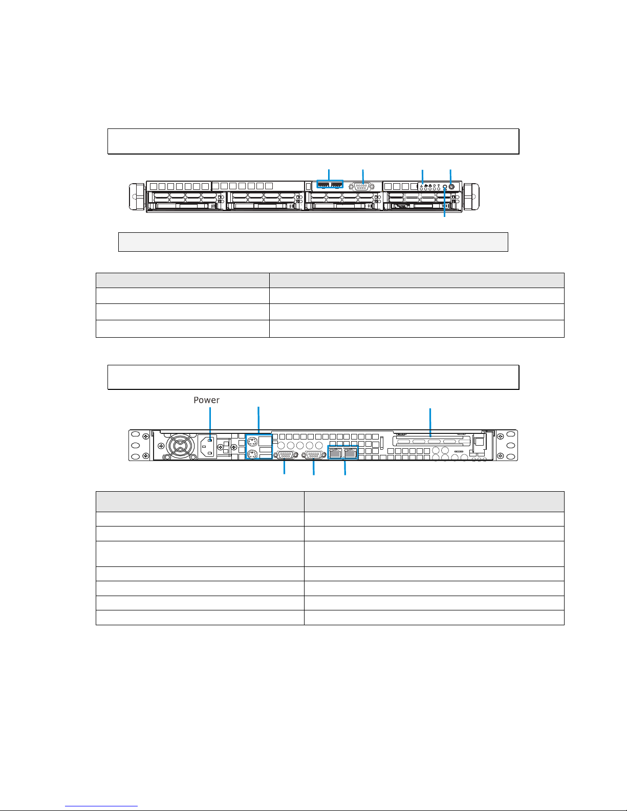
2.1. Front Panel
LED Panel Power Sw it c h
Res et Butt on
COM Po rt
USB Port
Note: The functions of USB port and COM port are reserved.
Item
Function
1. Power Switch
Powers up the NVR.
2. LED Indicators
Indicates the network, hard drive, and system status.
3. Reset Button
Reboots the NVR system.
2.2. Rear Panel
Mouse/Keboard/ USB Port
COM Po rt VGA Port LAN Port
SAS Exp an sion Port
Item
Function
1. Power Socket
Used for connecting power cable.
2. PS/2 Mouse/Keyboard Connector
Used for connecting mouse and keyboard.
3. USB Ports
Used for exporting video clips as evidence support to
external storage devices.
4. VGA Port
Used for attaching an external monitor to the NVR.
5. LAN Port (GbE Ethernet port) x2
Used for connecting the EMR with the network.
6. COM Port
Reserved.
7. SAS ports
SAS ports for RAID expansion purposes.
Page 23
23
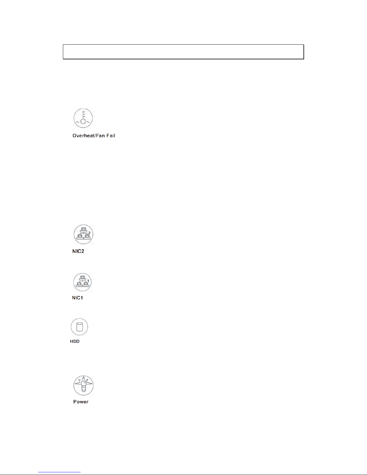
2.3. LED Definitions
The control panel located on the front of the chassis has five LEDs. These LEDs
provide you with critical information related to different parts of the system.
This section explains what each LED indicates when illuminated and any
corrective action you may need to take.
When this LED flashes, it indicates a fan failure. When on continuously it
indicates an overheat condition, which may be caused by cables obstructing the
airflow in the system or the ambient room temperature being too warm. Check
the routing of the cables and make sure all fans are present and operating
normally. You should also check to make sure that the chassis covers are
installed. Finally, verify that the heat sinks are installed properly (see Chapter
5). This LED will remain flashing or on as long as the indicated condition exists.
Indicates network activity on LAN2 when flashing.
Indicates network activity on LAN1 when flashing.
Channel activity for all HDDs. This light indicates SATA drive activity on the
NVR2100 when flashing.
Indicates power is being supplied to the system's power supply units. This LED
should normally be illuminated when the system is operating.
Page 24

24
Chapter 3. Hardware Installation
3.1. Installing the System into a Rack
This section provides information on installing the NVR2100 into a rack unit with
the rack rails provided. If the server has already been mounted into a rack, you
can skip ahead to other sections.
3.1.1. Identifying the Sections of the Rack Rails
You may have received rack rails with the NVR2100. (Two front inner rails
should already be attached to the chassis.) This hardware consists of two rear
inner rails that secure to the chassis, one on each side just behind the
preinstalled front inner rails. Note that these two rails are left/right specific.
3.1.2. Installing the Rear Inner Rails
First, locate the right rear inner rail (the rail that will be used on the right side
of the chassis when you face the front of the chassis). Align the two square
holes on the rail against the hooks on the right side of the chassis. Securely
attach the rail to the chassis with M4 flat head screws. Repeat these steps to
install the left rear inner rail to the left side of the chassis. You will also need to
attach the rail brackets when installing into a telco rack.
Locking Tabs: Both chassis rails have a locking tab, which serves two functions.
The first is to lock the server into place when installed and pushed fully into the
rack, which is its normal position. Secondly, these tabs also lock the server in
place when fully extended from the rack. This prevents the server from coming
completely out of the rack when you pull it out for servicing.
Page 25
25
Figure 3-1
Installing
Rear Inner Chassis
Rails
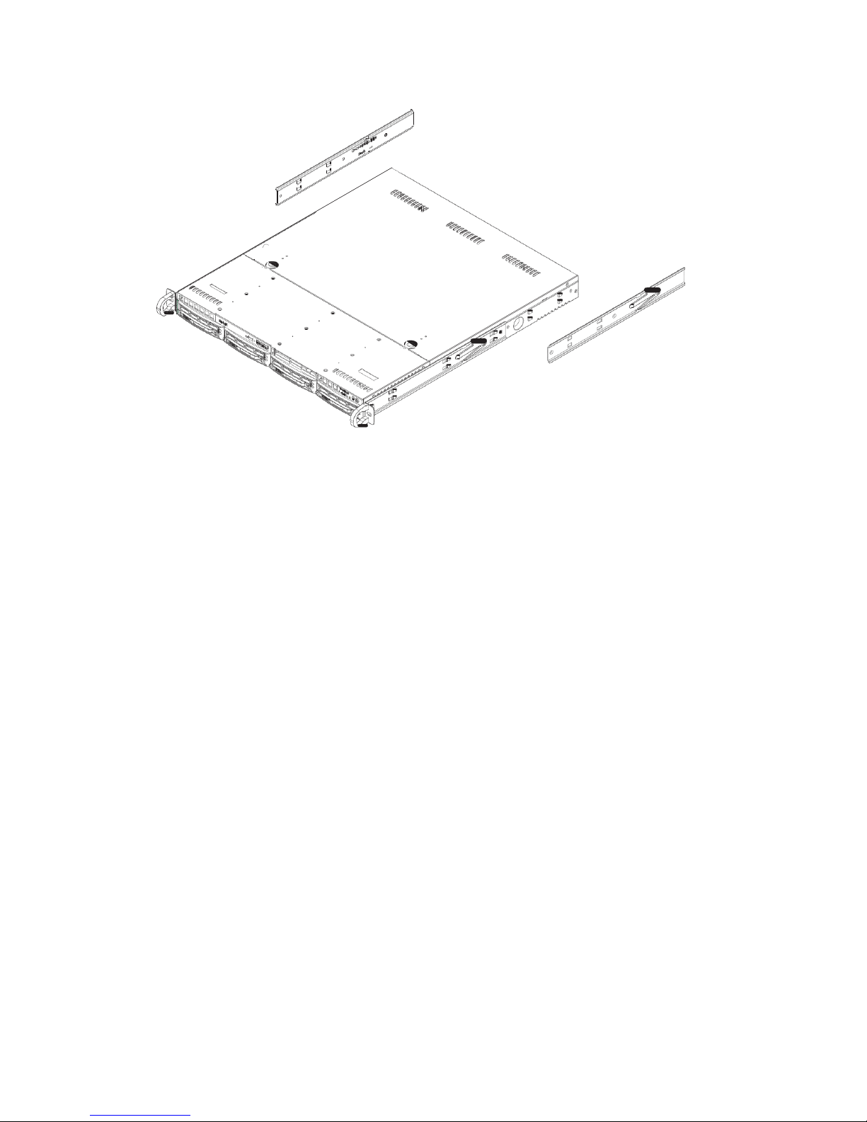
3.1.3. Installing the Rack Rails
Determine where you want to place the NVR2100 in the rack. Position the
chassis rail guides at the desired location in the rack, keeping the sliding rail
guide facing the inside of the rack. Screw the assembly securely to the rack
using the brackets provided. Attach the other assembly to the other side of the
rack, making sure that both are at the exact same height and with the rail
guides facing inward.
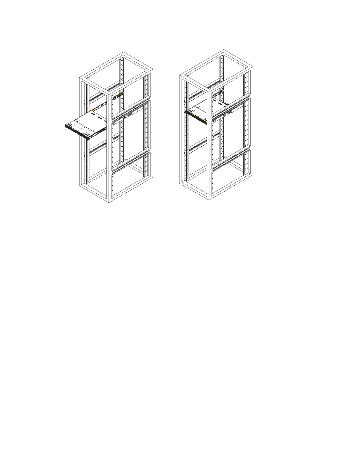
3.1.4. Installing the Server into the Rack
You should now have rails attached to both the chassis and the rack unit. The
next step is to install the server into the rack. Do this by lining up the rear of
the chassis rails with the front of the rack rails. Slide the chassis rails into the
rack rails, keeping the pressure even on both sides (you may have to depress the
locking tabs when inserting).
When the server has been pushed completely into the rack, you should hear the
locking tabs "click".
Page 26
26
Figure 3-2 Installing the Server into a Rack
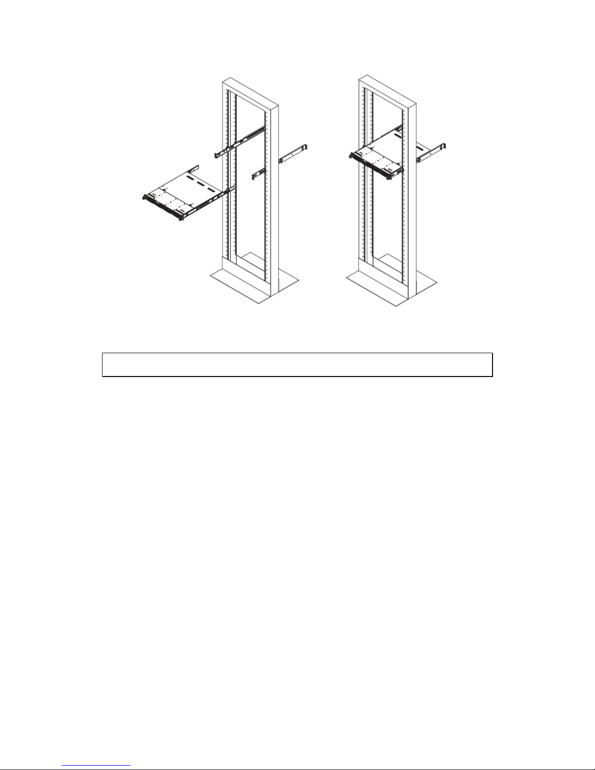
3.1.5. Installing the Server into a Telco Rack
To install the chassis into a Telco type rack, use two L-shaped brackets on
either side of the chassis (four in total). First, determine how far the server will
extend out the front of the rack. Larger chassis should be positioned to balance
the weight between front and back. If a bezel is included on your server,
remove it. Then attach the two front brackets to each side of the chassis, then
the two rear brackets positioned with just enough space to accommodate the
width of the rack.
Finish by sliding the chassis into the rack and tightening the brackets to the rack.
Page 27
27
Figure 3-3 Installing the Server into a Telco Rack
3.2. Checking the Drive Bay Setup
Next, you should check to make sure the peripheral drives and the SATA drives
and SATA backplane have been properly installed and all essential connections
have been made.
3.2.1. Checking the Drives
All drives can be accessed from the front of the server. The SATA disk drives can
be installed and removed from the front of the chassis without removing the top
chassis cover.
Depending upon your system's configuration, your system may have one or more
SATA drives already installed.
3.2.2. Providing Power
1. Plug the power cord from the power supply unit into a high-quality power
strip that offers protection from electrical noise and power surges. It is
recommended that you use an uninterruptible power supply (UPS).
Page 28
28
2. Depress the power button on the front of the chassis to power up the
system.
3.3. SATA Drive Carrier LEDs
Each SATA drive carrier has two LEDs.
Green: When illuminated, the green LED on the front of the SATA drive
carrier indicates drive activity. A connection to the SATA backplane
enables this LED to blink on and off when that particular drive is being
accessed.
Red: The red LED indicates two states. When blinking, it indicates the
drive is rebuilding. When solid, it indicates a drive failure. If a SATA
drive fails, you should be notified by your system management software.
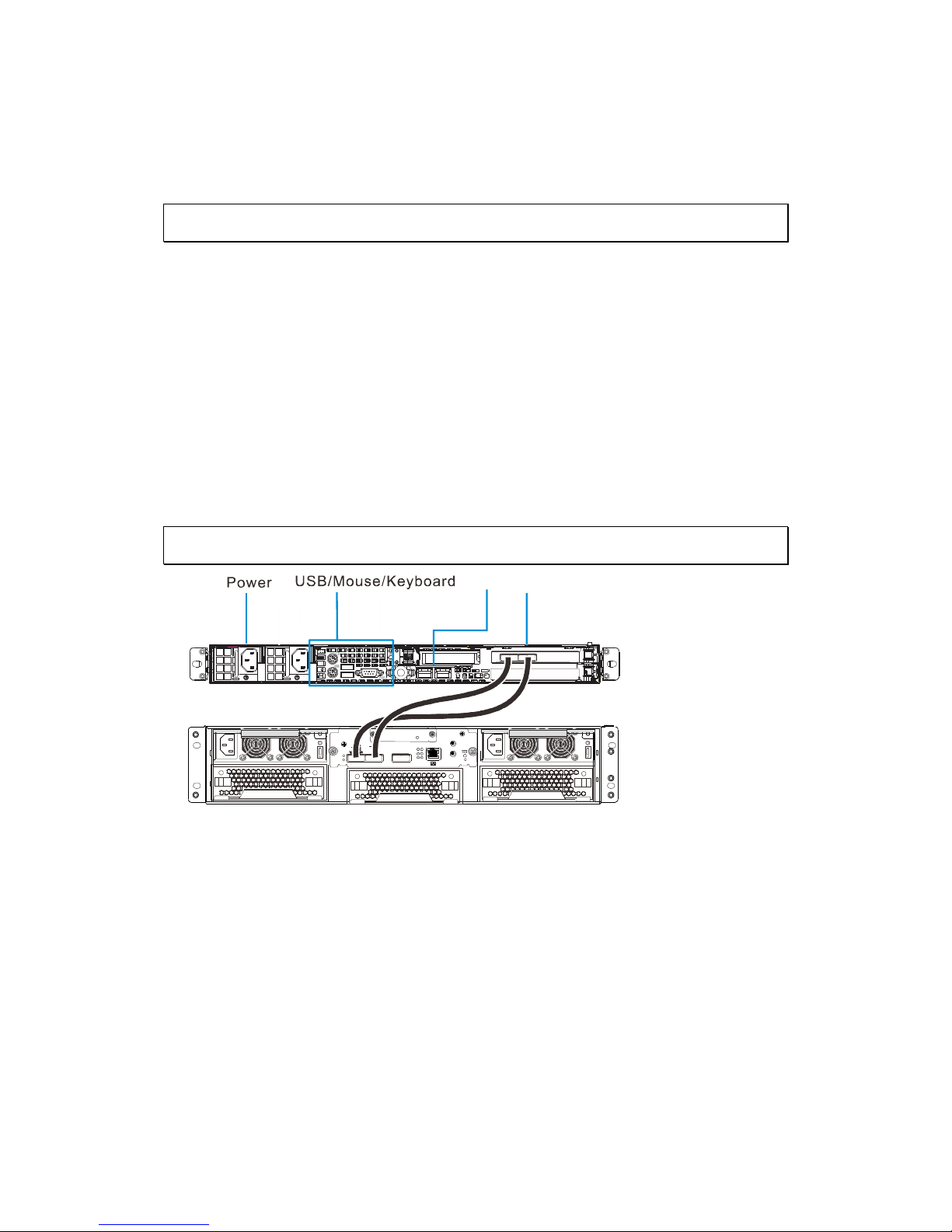
3.4. Making Host Connections
SAS cable
COM1
COM2
BBU Status
S
A
S
CH0 Link
CH1 Link
HOST-CH0 HOST-CH1 SAS Exp.
1.Ctrl Stat us
2.C_Dir ty
3.Temp.
4.BBU Lin k
5.Hst Bsy
6.Drv Bsy
1
2
3 6
5
4
LAN
Make the following connections:
LAN port: to connect the NVR2100 to the Internet.
SAS cable: to connect the NVR2100 controller to the storage
alley/enclosure.
Power cable
(Optional) USB port: to connect external devices such as CD-ROM for
recovery.
(Optional) Mouse and Keyboard.
Page 29
29
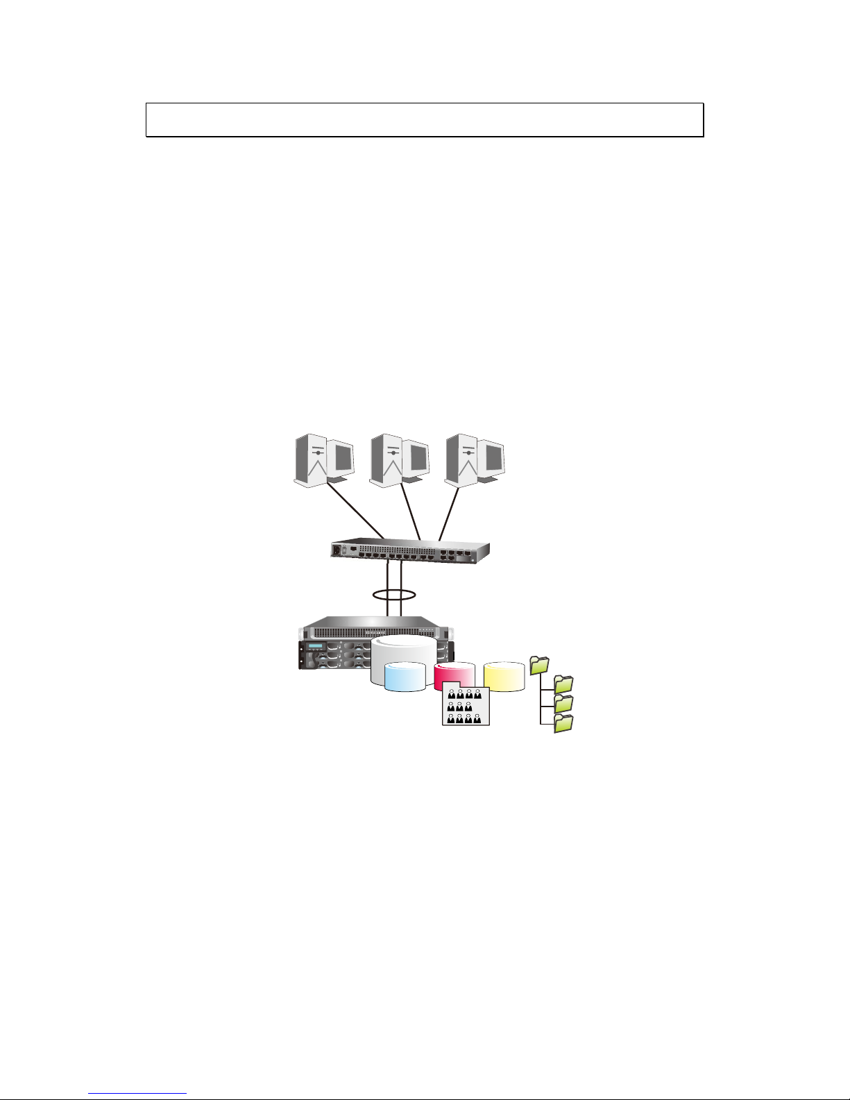
3.5. Making Network Connections
You do not need to connect other interfaces, such as VGA, mouse/keyboard, etc.
They are reserved for debug purposes. A web-based GUI is provided with the
server by connecting to LAN0 server IP.
LAN1 comes with a default IP: <10.0.0.2> and netmask 255.255.0.0.
Use a LAN cable to connect LAN1 from a laptop to start the initial access and
begin the initial setup such as changing its IP address. Ethernet cables are user-
supplied.
Use quality CAT5e cables.
It is preferred the server shares the same subnet with its clients.
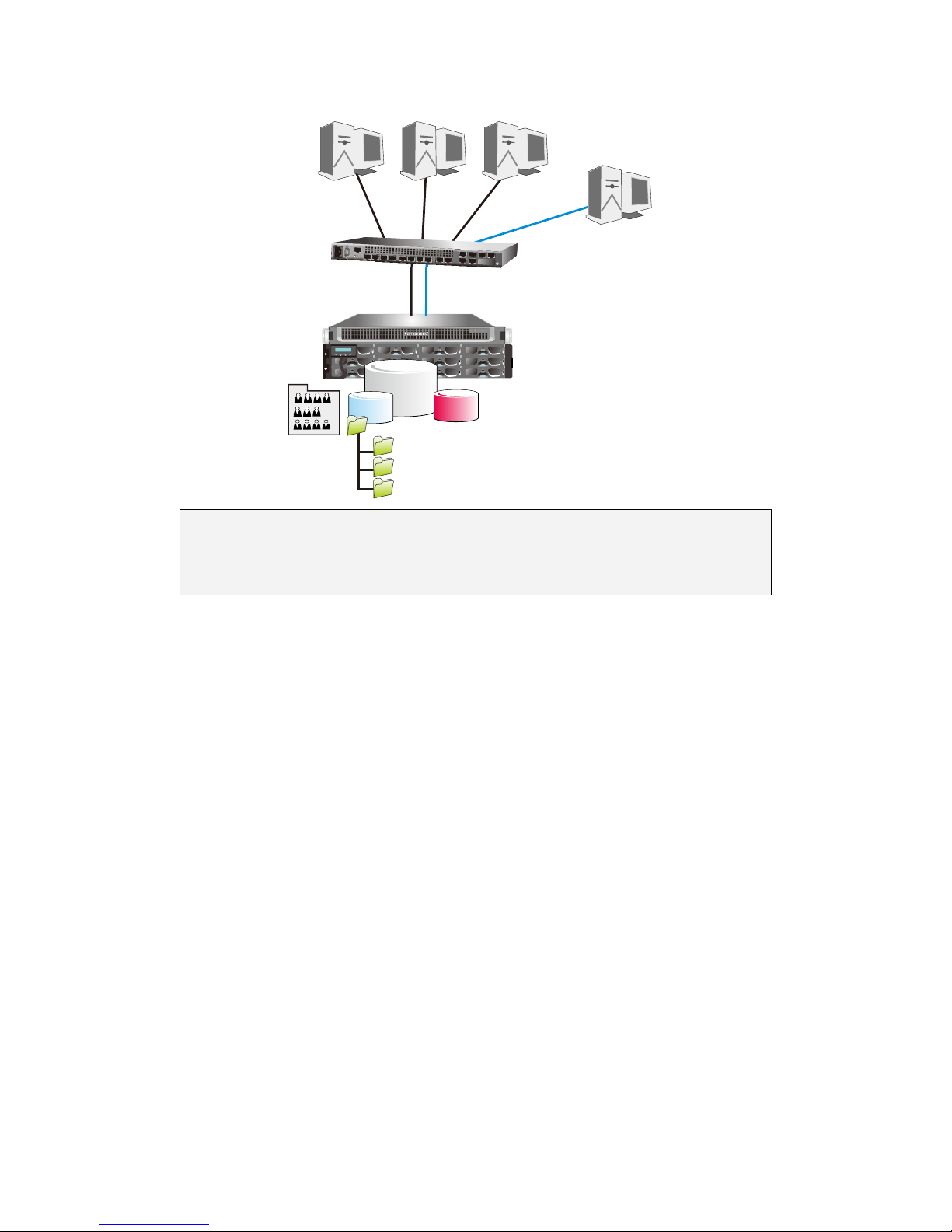
ESC ENT
PWR
BUSY
MUTEATTEN
Trunk (Link Aggregation)
192.168.0.1
192.168.0.1 192.168.0.1 192.168.0.1
NAS
server
GbE
switch
Trunk (Link Aggregation)
192.168.0.1
192.168.0.1 192.168.0.1 192.168.0.1
192.168.0.11 192.168.0.12 192.168.0.13
Pool &
shares
3.5.1. Cabling with iSCSI targets
You can also present a storage volume within a virtual pool as an iSCSI target.
The default iSCSI path is LAN0, and you might consider using LAN Masking or
LANto segregate different I/O paths. iSCSI CHAP authentication is also supported.
Page 30
30
ESC ENT
PWR
BUSY
MUTE
ATTEN
192.168.0.1
192.168.0.1 192.168.0.1
192.168.0.2
192.168.0.2
192.168.0.14
Initiator
NAS
server
GbE
switch
192.168.0.1
192.168.0.1
192.168.0.1 192.168.0.1
192.168.0.11 192.168.0.12 192.168.0.13
192.168.0.2
192.168.0.2
192.168.0.14
Initiator
iSCSI
Target
Pool &
shares
Note: For storage management for iSCSI connection, please refer to RAID
Configurations for Eonstor DS RAID Subsystem(s) section or SANWatch
User manual for more details.
Page 31

31
Chapter 4. Maintenance
This chapter covers the steps required to install components and perform
maintenance on the chassis.
Tools Required: The only tool you will need to install components and perform
maintenance is a Philips screwdriver.
4.1. Accessing the Drive Bays
SATA Drives: Because of their tray swap design, you do not need to access the
inside of the chassis or power down the system to install or replace SATA drives.
Proceed to the next step for instructions. Serial ATA Drive Installation
4.1.1. Mounting a SATA Drive in a Drive Carrier
The SATA drives are mounted in drive carriers to simplify their installation and
removal from the chassis. These carriers also help promote proper airflow for
the system. For this reason, even empty carriers without drives installed must
remain in the chassis.
1. Install a new SATA drive into the carrier with the printed circuit board
side facing down so that the mounting holes align with those in the
carrier.
2. Secure the drive to the carrier with six screws.
Page 32

32
4.1.2. Installing/Removing SATA Drives
To remove a carrier, push the release button located beside the drive LEDs.
Swing the colored handle fully out and use it to pull the unit straight out.
Note: Your operating system must have RAID support to enable the hot-plug
capability of the SATA drives.
4.1.3. SATA Backplane
The SATA drives plug into a backplane that provides power, drive ID and bus
termination.
Figure 4-3 Removing a SATA Drive from the Server
4.2. Power Supply
The NVR2100 has a single 300 watt power supply. This power supply has the
capability of operating at 100 - 240 input volts. Depress the main power button
on the front of the chassis and then unplug the AC power cord to completely
remove power from the system before removing the power supply.
Page 33

33
4.2.1. Power Supply Failure
If the power supply unit fails, the system will shut down and you will need to
replace the power supply unit. Replacement units can be ordered directly from
your dealer.
4.2.2. Replacing the Power Supply
To replace a power supply, you must first remove the top chassis cover. Follow
the procedure on the previous page.
1. First unplug the power cord from the system.
2. To remove the failed power unit, remove the two screws on the back of
the power supply, which secure it to the chassis. You can then lift the
unit straight out of the chassis.
3. Replace the failed unit with another unit of the same wattage. It is
highly recommended to replace it with the exact same power supply.
4. Carefully insert the new unit into position in the chassis and secure it
with the two screws at the rear of the unit.
5. Before reconnecting the power cord, make sure the power switch on the
power supply is in the off position. Then reconnect the power cord,
replace the chassis top cover and push the unit back into the rack.
6. Finish by turning the power switch on the power supply on, and then
depress the power button on the front of the system.
Page 34

34
Chapter 5. Software Overview
5.1. Introduction
Video Management Software (VMS) is a highly modular and powerful video and
hardware management suite that incorporates Server recording, management, and
video monitoring and playback functionalities to serve the core purposes of a video
surveillance system.
It operates in a client-server mode: The Local Client and Local Domain Server run
for standalone SMR/NVR/VMS Server, while the Remote Client receives live video
streams and event video playbacks from LAN or Internet. All administrative tasks
are performed on the Client. The client software provides the ability to monitoring
and playback recorded videos from multiple cameras. And for users having multiple
SMR/NVR/VMS Servers, Central Management Software (its main functions are the
same with the VMS) can be utilized to manage over the domain infrastructure.
5.2. Module Framework
VMS/NVR Server
Combines video recording, archival and retrieval functionalities for
individual servers/standalone PCs.
Serves as the connection point for client stations.
Local Domain Server
The interface between the VMS/VI Servers and any clients.
User authentication server.
Local Client
Local access, VMS Client installed on standalone PCs/SMRs for live
video monitoring, event recording playback access and VMS system
configuration.
Remote Client (full functions)
Remote access, VMS Client installed on remote PCs for live video
monitoring, event recording playback access.
Serves as the default configuration point for NVR2000 series, which do
not have a Local Client.
Page 35

35
Web Client (for simple use)
Remote access, an ActiveX application (OCX) installed on remote PCs
for live viewing and event playbacks through the web browser.
SPhone Client (for simple use)
SPhone Client installed on iOS/ Android devices for basic live viewing.
Web Server
Allows user to access the live video stream, PTZ control and event
recording playbacks through Microsoft Internet Explorer 7.0 (or higher)
after the Web Clients components are downloaded.
VI Server
The video intelligence processing point for a VMS solution.
Preinstalled on SMR/NVR Server, and optional on a separate server/PC
(VMS).
SCC Domain Server
Allows centralized control over multiple Trusted VMS Server points and
connections from multiple clients.
SCC Client
Software capable of accessing multiple Trusted VMS Servers through
the SCC Domain Server.
Page 36

36
5.3. System Architecture
VMS operates in scalable client - server architecture. This architecture can be
divided into three types: (1) Standalone Server (2) Standalone Server + Remote
Client (Web Client/SPhone Client) (3) Multiple Servers + SCC Client.
These are the hardware requirements for using PCs as Server or Client.
VMS Server + Client
Support NVRs
≥ 32CH
16~32CH
≤ 16CH
OS
64-bit :
Windows 7 Professional, Enterprise, Ultimate
CPU
Intel Core i7‐980X or
above
Intel Core i7‐860
or above
Intel Core i5‐650
or above
Memory
4 GB or above
Display
nVidia GeForce GTX660 2GB or above
Hard Drive
SATA 7200 RPM, 500 GB or above
Network
1 Gbps or above
Remote Client
OS
64-bit :
Windows 7 Professional, Enterprise, Ultimate
CPU
Intel Core i7‐980X
or above
Intel Core i7‐860
or above
Intel Core i5‐650
or above
Memory
4 GB or above
Display
nVidia GeForce GTX660 2GB or above
Hard Drive
SATA 7200 RPM, 500 GB or above
Network
1 Gbps or above
VMS Server Only
OS
64-bit :
Windows 7 Professional, Enterprise, Ultimate
CPU
Intel Core i3‐530 or above
Memory
4 GB or above
Display
On board (generic) 256MB or above
Hard Drive
SATA 7200 RPM, 500 GB or above
Network
1 Gbps or above
Page 37

37
5.3.1. Standalone Server (Client-Server All-in-One)
For users with standalone Server, the Local Client UI is used to manage SMR
Server services:
※Application:
The Server, IP cameras are all in the same LAN.
Standalone Server (Client-Server All-in-One)
NVR Server
Local Client
VI Server
Standalone Server + Remote Web Client
Use SMR as Server
No installation needed.
Use PC as Server
Install both the VMS/NVR Server and VMS Client on a PC:
Insert the VMS/IPCAM product CD.
Click VMS Suite on the menu to start the installation.
Page 38

38
Choose Typical Setup. If you don’t need video analytic functions, Advanced
Setup can be selected to uncheck the VI Server.
Page 39

39
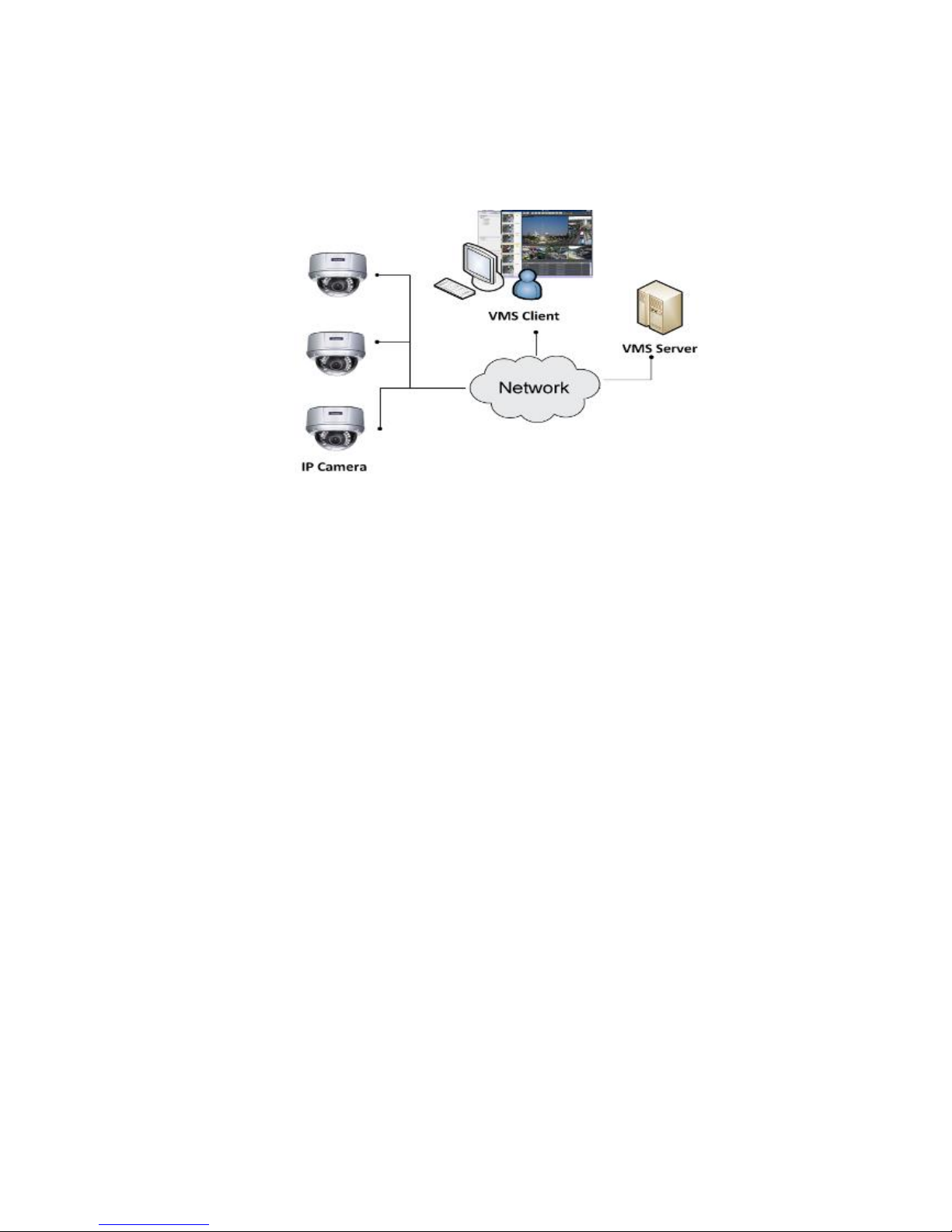
5.3.2. Standalone Server + Remote Client (Web
Client/SPhone Client)
For remote users to connect to SMR/NVR Server, a remote access, VMS Client
installed on remote PCs is needed for live video monitoring, event recording
playback access.
Also, the Web Client, an ActiveX application (OCX) can be used for basic live
viewing and event playbacks through the web browser, while SPhone Client can
be used for basic live viewing on iPhone/Android devices.
Page 40

40
※Application1: Internet
The Server, IP cameras and the PC/iPhones are all in the same LAN.
[NVR Server]
Use SMR/NVR as Server
No installation needed.
Use PC as Server
Install the VMS/NVR Server on a PC:
Insert the VMS/IPCAM product CD.
Click VMS Suite on the menu to start the installation.
Choose Advanced Setup to uncheck the VMS Client. If you don’t need video
analytic functions, the VI Server can also be unchecked.
Install the Web Server on the PC:
Insert the VMS/IPCAM product CD.
Click Browse CD/DVD in the menu.
Double click WebServerSetup.exe to start the installation.
[Client]
Install the VMS Client on PCs:
Insert the NVR/SMR product CD.
Click VMS Client on the menu to start the installation.
Install the Web Client on the PCs (Optional):
Page 41

41
Install the SPhone Client (Optional):
Download the SPhone Client from App Store on the iPhone desktop.
Install the SPhone Client (Optional)
Download the SPhone Client from App Store on the Andriod phone desktop.
Note: Please refer to Installing the VMS and Installing the Web Client for details.
Page 42
42
※Application 2: Internet
The Server, some of the IP cameras and the PC are all in the same LAN, while
the other IP cameras are installed in remote location with Public IP.
Page 43

43
5.3.3. Multiple Servers + SCC Client
For users with multiple SMR/NVR Servers, SCC Client UI is used to manage over
the domain infrastructure.
※Application: Internet
(1) The Servers, IP cameras and the PCs are in LAN A.
(2) Some IP cameras are installed in LAN B, which is behind a different router in a
remote location.
(3) Users are allowed to connect the SMRs/NVRs from remote PC over the Internet.
Page 44

44
CMS Client
NVR
Server
VI Server
CMS Domain Server
CMS Client
Multiple Servers + CMS Client
NVR
Server
NVR
Server
[NVR Server]
Use SMR/NVR as Server
No installation needed.
Use PC as Server
Install the VMS/NVR Servers on PCs:
Insert the VMS/IPCAM product CD.
Click VMS Suite on the menu to start the installation.
Choose Advanced Setup to uncheck the VMS Client. The VI Server can also be
unchecked, if you don’t need video analytic functions.
[VI Server] (Optional)
You can choose to install the VI Server only on a standalone PC to manage the
video intelligence data.
Insert the VMS/IPCAM product CD.
Click VMS Suite on the menu to start the installation.
Choose Advanced Setup to choose VI Server only.
[SCC Domain Server]
Install the SCC Domain Server on a PC:
Insert the NVR/SMR product CD.
Click SCC Suite on the menu to start the installation.
Choose Advanced Setup to select the SCC Domain Server only.
Page 45

45
[SCC Client]
Install the SCC Client on PCs:
Insert the NVR/SMR product CD.
Click SCC Suite on the menu to start the installation.
Choose Advanced Setup to select the SCC Client only.
Note: (1) For users don’t have Surevon SMR/NVR series, please contact your
dealer for the SCC installation file. (2) The SCC Domain Server can also be
installed together with the SCC Client in the same PC by choosing Typical Setup.
(3) Please refer to Installing the VMS and Installing the SCC for details.
Page 46

46
5.3.4. Network Requirements
In order to preserve enough bandwidth for surveillance video, a surveillance
network is presumed to be free of user/business traffic. Server software
currently supports Class B and Class C type addresses. Currently the Server
software only searches for Servers on the same subnet. Cameras should also
reside on the same subnet.
Configuring Windows Firewall Exceptions
The Windows firewall will block incoming network connections, so the VMS
should be added to the firewall exceptions list. The instructions below are for
Windows XP, however the process is similar under Vista and Windows 7.
1. Open Settings > Control Panel > Windows Firewall.
2. Under the Exceptions tab, click Add Program…
3. Click browse and go to your install directory.
4. Select NVRService.exe.
5. If you require DHCP services, repeat steps 3 and 4 and add dhcpsrv.exe
Page 47

47
6. Click OK to save your settings.
Opening Ports
If access through a firewall in a local network is required, try opening the
following ports: SMTP (25), HTTP (80), FTP (20, 21), OMNI (2809), HTTPS (443) and
RTSP (554, 8554.). Other ports should also be opened while using port forwarding
to access the VMS Server: Stream Port (9090), Doman Data Port (9060), Log
Download Message Port (15507) and Log Download Data Port (9080).
Note: Please refer to Port Forwarding Section for more details.
Warnings / Precautions
If the Server and a VMS client reside on separate subnets, please set up gateway,
VLAN, or cross-subnet routing to bridge surveillance traffic. Please consult with
a network administrator for problems with network setups. A VMS client needs
to be rebooted when network settings are changed.
5.3.5. Windows Vista/7 User Notes
Page 48

48
Windows Vista and 7 users may experience problems with the video
display/overlay when using certain themes. If you experience these problems,
we recommend you change your theme to Windows Classic under Control Panel
> Appearance and Personalization > Personalization.
In Windows Vista and Windows 7, User Account Control (UAC) is a security
infrastructure that restricts application privileges. This feature must be disabled
for the recording functionality of the VMS to work correctly. To disable UAC,
first open a command prompt by selecting All Programs> Accessories >
Command Prompt. At the command line, enter the following command:
C:\Windows\System32\cmd.exe /k %windir%\System32\reg.exe
ADD HKLM\SOFTWARE\Microsoft\Windows\CurrentVersion\Policies\System /v
EnableLUA /t REG_DWORD /d 0 /f
To re-enable UAC use the following command:
C:\Windows\System32\cmd.exe /k %windir%\System32\reg.exe
ADD KLM\SOFTWARE\Microsoft\Windows\CurrentVersion\Policies\System
/v EnableLUA /t REG_DWORD /d 1 /f
Page 49

49
5.4. Port Forwarding
Port forwarding is a name given to the combined technique of:
1. Translating the address and/or port number of a packet to a new
destination.
2. Possibly accepting such packet(s) in a packet filter (firewall).
3. Forwarding the packet according to the routing table.
To illustrate its concept, two computers on the Internet that communicate with
each other using TCP/IP or UDP/IP protocols(though the process is not limited to
these) utilize ports to identify the opposite connection points of each other where
the data packets supposed to go to. In order to communicate, each computer
knows the port of another computer (in addition to IP address) and sends the data
to that port. Port forwarding forwards these ports in such a way that when one
computer sends data to the specific port of another computer, the data is actually
sent to a different port. This allows remote computers to connect to a specific
computer or service within a private LAN.
In a typical residential network, nodes obtain Internet access through a DSL or
cable modem connected to a router or network address translator (NAT/NAPT).
Hosts on the private network are connected to an Ethernet switch or communicate
via a wireless LAN. The NAT device's external interface is configured with a public
IP address. The computers behind the router, on the other hand, are invisible to
hosts on the Internet as they each communicate only with a private IP address.
When configuring port forwarding, the network administrator sets aside one port
number on the gateway for the exclusive use of communicating with a service in
the private network, located on a specific host. External hosts must know this port
number and the address of the gateway to communicate with the network-internal
service.
When used on gateway devices, a port forward may be implemented with a single
rule to translate the destination address and port. The source address and port are,
in this case, left unchanged. When used on machines that are not the default
gateway of the network, the source address must be changed to be the address of
the translating machine, or packets will bypass the translator and the connection
will fail.
Page 50

50
5.4.1. Port Forwarding for Accessing VMS Server
To enable port forwarding for accessing VMS Server, please follow the steps below:
1. Do Router Port Mapping for VMS/NVR Server
Go to Setup > Other Tasks > Server > Router Port Mapping in VMS after it is
installed.
Note: The VMS/NVR Server is preinstalled in NVR2000/SMR Series.
A Router Port Mapping window will prompt for entering port numbers. Please put
in the numbers as listed below:
Stream Port: 9090
Login: Port: 2809
Doman Data Port: 9060
Log Download Message Port: 15507
Log Download Data Port: 9080
Page 51

51
2. Open Ports on the Router
Host Ports: The private ports that the internal VMS/NVR Server use, which are
unchangeable.
Global Ports: The public ports for remote clients to connect to the internal
VMS/NVR Server. The Global ports are changeable, but the simplest way is to
make them the same with the host ports.
Please open the listed ports on your router:
Port(Host/Global Port)
Protocol
Port Number
Domain Message Port
UDP
9050
Domain Data Port
TCP
9060
Login Port
TCP
2809
Stream Port
TCP
9090
Log Download Message Port
TCP
15507
Log Download Data Port
TCP
9080
Page 52

52
Note: Camera port (default: 80) and stream port (default: 6002) for accessing
cameras should be opened while VMS/NVR Server and the cameras and are not in
the same LAN.
Page 53

53
5.5. Installing the VMS
Note: For NVR2000/SMR series, users have to install VMS Client on remote PC(s)
when distant live viewing and playback are needed.
1. Insert the VMS/IPCAM CD-ROM. The CD should autorun. If it does not,
open the CD manually and double-click autorun.exe. The menu below
will be displayed.
Click VMS Suite to start the installation.
Page 54

54
2. Choose a setup type from Typical and Advanced. Then Click Next when
you are satisfied with your selection.
3. You may choose to install among the following while Advanced
Setup Type is selected:
a. VMS Server Suite – Includes the VMS Server and Local Domain
Server, VI Server and VMS Client.
b. VI Server
c. VMS Client
d. Web Server
Page 55

55
4. The confirmation screen will display. Click Install. A progress bar will
display, indicating installation progress.
5. When installation is finished, an informational screen will display.
Click Finish to complete installation.
Page 56

56
6. The system will prompt for a restart. A restart is required before the
VMS will function correctly. You may choose to immediately
automatically restart your computer, or restart your computer later.
Clicking Finish will apply your choice.
Page 57

57
5.6. Starting the VMS Client
To start the software, click Programs > VMS Suite > VMS Client under the
Windows Start menu.
The software will prompt for the following information:
Access Method – Directly Access or Internet Port Forward.
Type – Choose VMS.
Server – The IP address for the VMS/NVR Server. You can click Search
button to obtain it. For users of port forwarding, it should be the IP
address of the router.
Port – The Login Port for port forwarding - 9050. It should be set
under Server > Other Tasks > Port Mapping after the first login.
Note: (1) Please refer to Port Forwarding Section for more details. (2) SCC does
not support port forwarding functionalities.
Username – The username for the domain, which is always admin.
Password – The password for the domain. Default password is admin.
Click Login after the password (and port number) is entered.
Page 58

58
5.6.1. Checking the Software Version
Users can see the software version at the lower right corner of the window after
logging in.
5.6.2. Logging out
The Client can be logged out of all the Servers configured on the system by
pressing the Logout button on the upper right hand corner in the GUI. Logging
out of individual servers can be achieved by double clicking the server entry and
clicking the Yes button on the confirmation screen.
Closing the window using the X button on the top right corner will exit the
Client. A confirmation screen will appear, click Yes to exit the system.
Note: (1) If the system becomes unresponsive, users can force shutdown the
system (press and hold the power until the system shuts down). This should only
be done when the system is unresponsive!
Page 59

59
Chapter 6. Basic System Settings
6.1. Storage Management
1. To access the information about the drives configured in your Server,
highlight and click the Storage Manager option under Server Settings.
2. All available Logical Drives, as well as their sizes, free space, and status will
appear.
Click Edit to set the log and location for saving the video recordings.
(Step 3 and 4 are for the remote client of NVR2000/SMR Series.)
Page 60

60
3. Click the target drive first and then Settings.
In “Advanced Settings” dialogue, “General” tab, click Check.
4. Choose the RAID level, and then click Create Logical Drive to create the
RAID configuration.
Note: Storage Manager can also be accessed by clicking Server > General Tasks
> Storage or Server Entry > Common Tasks > Common Server Tasks >
Storage in the VMS Console.
Page 61

61
6.2. Adding Cameras to the Server
Cameras can be added to the Server in two ways: via an automatic scan or by
manually inputting the camera information.
6.2.1. Automatic Scan for Cameras
To begin an automatic scan for cameras:
1. Right-click the Server entry and select Scan for Cameras. The system will
respond by beginning an automatic scan. Once the scan is complete, the
cameras that can be added to the Server will be displayed. Information
available for each camera will include:
Name – The default camera name (Make/Model)
Status – The camera will display New if it has not been added to
this Server, otherwise it will display Assigned.
IP Address
MAC Address
Vendor - Including ACTI, ASONI, AVTECH, AXIS, Arecont, Sosch,
Brickcom, DyNACOLOR, D_Link, Dahua, EDIMAXHIKVISION,
EverFocus, HIKVISION, IQinVision, Lilin, Eessoa, Mobotix,
ONVIF, Panasonic, SIMON, SONY, Samsung, Surveon, VIVOTEK,
and General.
Model - when “General” is selected, “RTP over TCP” and “RTP
over UDP” can be further defined.
2. To add a camera to the system, check the box by the camera entry. You
may also check the Select All box at the bottom of the window to select
all the cameras found.
Enter the username and password, and press Apply Selected. Click OK
to add the selected cameras to the Server.
Page 62

62
The following windows will prompt for validation.
Page 63
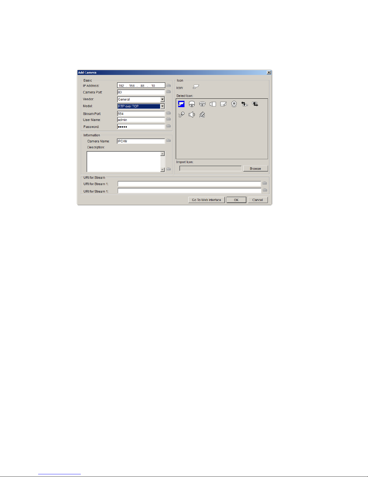
63
3. (Optionally) Double-click any camera entry to bring up the camera detail
page. From this page you may change the following information:
IP Address – Changing this value will affect connectivity.
Camera Port – The web access port, default is 80.
Stream Port – Default is 6002.
Vendor – Changing this value will affect connectivity.
Model – Changing this value will affect connectivity.
User Name – This value is not always required.
Password – This value is not always required.
Camera Name – It is recommended you change this value if you
have more than one camera of this make/model.
Camera Description
Camera Icon – You can also import your own icon by clicking on
the Browse button and choosing an icon file. Valid icon files
include JPEG, GIF, PNG, BMP and ICON files.
Finally, you can access the web interface for the camera by clicking on
the Go to Web Interface button. Click OK to save your changes, or
Cancel to exit without saving.
4. (Optionally) You may access the IP Utility for camera configurations by
clicking the IP Camera Utility button.
5. Click OK to add the selected cameras to the Server.
Page 64

64
Note: Automatic Scan for Cameras can also be accessed by clicking Camera List >
General Tasks > Scan for Cameras or Server Entry > Common Tasks > Common
Server Tasks > Scan for Cameras in the VMS Console.
6.2.2. Manually Adding Cameras
To manually add a camera to the Server:
1. Right-click the Server entry and select Add Camera.
2. In the camera window fill out the following information:
IP Address
Camera Port – This value will automatically populate with the
default value for the Vendor and Model selected.
Vendor - Including ACTI, ASONI, AVTECH, AXIS, Arecont, Sosch,
Brickcom, DyNACOLOR, D_Link, Dahua, EDIMAXHIKVISION,
EverFocus, HIKVISION, IQinVision, Lilin, Eessoa, Mobotix,
ONVIF, Panasonic, SIMON, SONY, Samsung, Surveon, VIVOTEK,
and General.
Page 65

65
Model: “General” is selected, “RTP over TCP” and “RTP over
UDP” can be further defined.
Stream Port – This value will automatically populate with the
default value for the Vendor and Model selected.
User Name – This value is not always required.
Password – This value is not always required.
Camera Name – It is recommended you change this value if you
have more than one camera of this make/model.
Camera Description
Camera Icon – You can also import your own icon by clicking on
the Browse button and choosing an icon file. Valid icon files
include JPEG, GIF, PNG, BMP and ICON files.
When there’s no suitable option for your device, you can select
“General” from the Vendor dropdown list and defined if it’s a “RTP
over TCP” or a “RTP over UDP” from the Model dropdown list.
Once set, define URI for Stream 1.
See the reference below for further setting.
For an AXIS IP camera,
key in “RTSP://<IP of the IP camera>/<codec>/media.amp”
For a HIKVISION IP camera,
key in “RTSP://username:password@<IP of the IP Camera>”
For a Surveon IP camera,
key in “RTSP://<IP of the IP camera>/stream1 or stream2”
4. Finally, once basic camera information is filled in, you may access the
web interface for the camera by clicking on the Go to Web Interface
button. Click OK to add the camera.
Note: Cameras can also be added manually by clicking Camera List > General
Tasks > Add Camera in the VMS Console.
Page 66
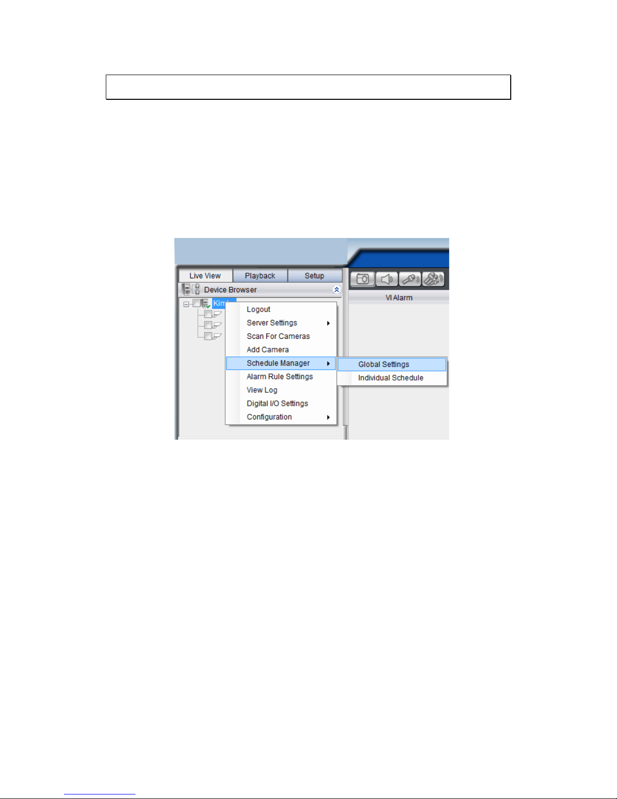
66
6.3. Setting Recording Schedule
A global Schedule applies to all cameras, while individual schedules are for
each camera. Individual schedules take precedence over global schedules.
6.3.1. Weekly Scheduling
1. Right-Click the VMS entry and choose Schedule Manager > Global
Settings or Individual Schedule to bring up the Weekly Schedule popup.
2. If setting individual schedule and more than one camera is configured,
choose the camera you wish to set from the list.
3. The schedule grid corresponds to every hour in the week. Click on one
of the four recording methods and then click on the grid area to “paint
in” the method for the corresponding hour.
4. Click the Apply button to apply the schedule and OK to exit the dialog.
Page 67

67
5. (Optional) You may go to the VI setting panel by clicking Go to VI
Settings.
Page 68

68
6.3.2. Daily Scheduling
1. Right Click the server entry and choose Add Daily Schedule.
2. Click the Select Date selection box and choose the date that you want
to schedule.
3. Click on one of the methods and then click on the grid area to “paint in”
the method for the corresponding hour.
4. Click OK to apply the changes.
Page 69

69
6.4. Adding Alarm Rules
Alarm rules can be created using the following elements:
Rule: A short description. For example, “east–fence intrusion detection”
or “front entrance access control.”
Condition: Specifies triggering conditions such as Motion/Video
loss/Sensor input/Clock Alarm, etc.
Action: Specifies the action to take when the alarm is triggered.
Schedule: Allows the user to schedule the application of specific Alarm
rules. This is useful in cases such as applying rules to non-office hours.
1. Right-click the NVR entry and select the Alarm Rule Settings option
under VMS node.
Page 70

70
2. Click the New button.
3. Enter name for the new rule and click OK to create the rule.
4. Choose conditions for the Alarm. Detailed settings can be changed by
clicking Details.
5. Select actions for the alarm. Detailed settings for actions can be set by
clicking Action.
6. Click the……button in the alarm field to set up a schedule for the rule.
Default scheduling is record always on.
7. Click the Save button to save the rule.
Page 71

71
6.5. Setting up Live View
An important part of monitoring your surveillance network is to have the right
views so that you will have the optimum viewing angle to discern a situation.
The default view setting is 3x3.
You can also add a customized view to the VMS Client:
1. Right click on Views > Add View in the View Explorer window of the
VMS, and choose the type of view that you wish to add. The software
responds by placing a blank template in the main viewing area.
2. From the Device Browser window, you can click and drag each camera
into separate frames. The camera output will be displayed in the frame.
When two cameras are dragged into the same view, a popup window will ask
you whether you want to use the latter camera to replace the former one.
Page 72

72
Chapter 7. Live View
Live viewing is a crucial part of any surveillance system. Having the right view
can be the crucial difference between catching an event as it happens and
missing it altogether. VMS provides powerful tools to manage the viewing
experience to help ensure that monitoring personnel are always on top of any
event.
7.1. Live View Window Overview
The live view window is split into 14 distinct parts:
1. Live View / Playback Selection Tabs – Allows users to choose live view
and playback mode.
2. Device Browser – Lists the Servers in the domain.
3. View Explorer – Lists the views that are configured on this client.
4. E-Map Explorer – Lists the E-maps available on this Server.
5. Live View Control – Interface for interacting with PTZ-enabled
cameras.
Page 73

73
6. Arrows for open up or close in the image panel and the VI Alarm
panel.
7. VI Alarm –Area for alarm notification and instant playback.
8. Window Toolbar – Lock the window, minimize the window, or leave
the system.
9. View/Account Information – This area contains general information.
Arrow button containing Server configuration options. Question mark
indicates Help File. Logout button for a quick logout.
10. Button Area - This area contains the buttons to change views, enter
full screen mode, capture photos, send audio files to the chosen / all
cameras and other useful functions.
Snapshot
Volume control
Talk to the chosen camera
Broadcast to all the cameras
Full screen mode
Viewing screen modes
Auto page flip between pages
Reset all the settings, including page
auto-flipping and different screen
divisions
11. Main View Area – This area contains the actual video feed(s).
12. Event Log Window – Close or send to another window for a better
view of the Event Log.
13. Event Log - This area contains alarm and event information.
14. Version – Shows the current VMS version.
Page 74

74
7.1.1. Resizing and Minimizing Windows
Minimizing Controls
The Device Browser, View Explorer, E-Map Explorer, Live View Controls, and
Event Log can all be minimized by clicking on the arrow buttons on the top-right
corner of their screens.
Hiding and Showing the Explorer Area
The entire left panel (containing the Live View/Playback Selection Tabs, Device
Browser, View Explorer, E-Map Explorer, and Live View Controls) can be hidden
by clicking on the arrow on the left of the Live View Control.
Page 75

75
7.2. View Setup
7.2.1. Types of Views
The VMS/NVR server supports viewing of up to 32 cameras in a single view, with
views of up to 36 cameras.
Views with more subdivisions are more useful for giving an overview of an area,
while ones with fewer subdivisions give better details. Multiple views can also
be displayed in sequence or in separate windows for managing more than 16
cameras.
Page 76
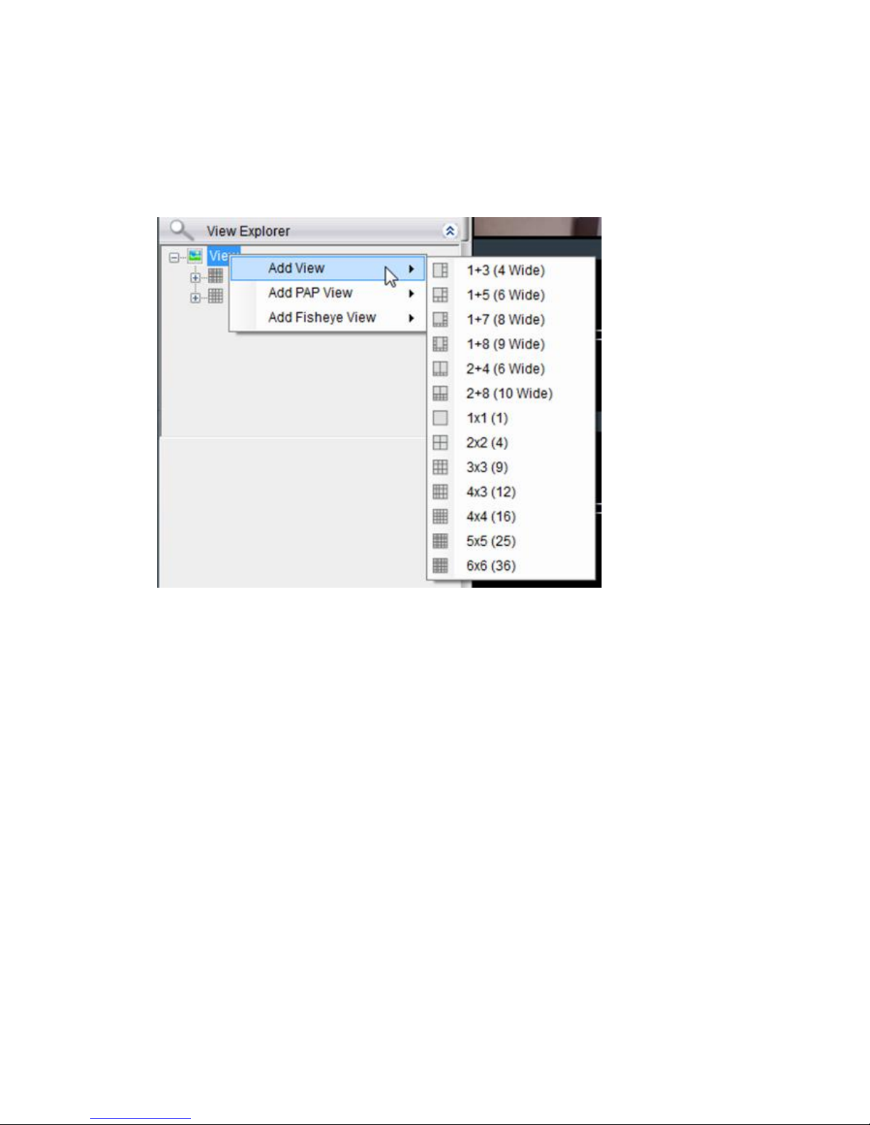
76
7.2.2. Adding a View
An important part of monitoring your surveillance network is to have the right
views so that you will have the optimum viewing angle to discern a situation. To
add a customized view to the VMS client:
1. Right click on Views in the View Explorer window, and choose the Add
View option, the software will respond by listing available screen
division types.
2. Choose the type of view that you wish to add by clicking on the view.
The software responds by placing a blank template in the main viewing
window that has been subdivided into individual frames according to the
view selected. The empty frames will display the message No camera.
3. From the Device Browser window, you can click and drag the entries for
individual cameras into the separate frames. The camera output will be
displayed in the frame. Cameras in the view do not have to all be from
the same server.
Dragging a camera into a frame that already has a camera assigned to it will
cause the frame to be reassigned to the new camera. You can also drag the
same camera into multiple frames or leave frames blank, although this is not
suggested.
Page 77

77
The View Explorer will be updated as you add cameras to your view. The root
will list the camera numbers that have been added to the view starting from the
top left frame and going from left to right and top to bottom.
Note: Depending on your connection and computer speed, it may take a
moment for the image to refresh after dragging the camera into the view
window. During this time the frame may still display No Camera or Failed to
connect. If this problem persists, however, there may be a problem with your
connection or hardware.
7.2.3. Add PAP View
PAP (Picture and Picture) View allows you to select multiple regions from one
image to zoom.
1. Right-click the View entry in the View Explorer window. This will bring
up an options popup.
2. Select “Add PAP View” and then select the desired window number. 1
indicates the main original image and the number behind “+” means the
numbers of the zoomed areas that you are about to create. For
example, 1+8 means 1 main original image + 8 zoomed areas.
3. Drag the set value from the View Explorer to the main image window.
4. Drag the desired camera from the Device Browser to the main image
window. Images from the camera you dragged will appear on the main
image window.
5. Move your mouse to select one window from the zoomed windows on
the right. From the main image window use your mouse to drag out an
area you’d like to zoom for the selected zoomed window. Zoomed
images will appear on the zoomed windows.
Page 78

78
6. Repeat Step 5 to create more zoomed areas; 8 zoomed areas can be
created when you set the PAP view to 1+8.
7. Move the cursor to the box of the unwanted region and left click to see
the options, Clear Region (clear 1 selected region)/ Clear All (clear
every created region).
7.2.4. Add Fisheye View
Viewing angles are crucial for fisheye cameras to capture images and
different installation method can affect the viewing angles. Fisheye viewing
is supported in VMS.
1. Right-click the View entry in the View Explorer window. This will bring
up an options popup.
2. Select “Add Fisheye View” and then “1x1(1)”.
3. Drag the desired camera from the Device Browser to the main window.
Images from the camera you dragged will appear on the main image
window.
4. Select according to the way your fisheye is installed to have a best
viewing result, Ceiling Mount, Table/Floor Mount or Wall Mount.
Page 79

79
5. The distorted hemispherical image of the fisheye camera can be
converted into a conventional rectilinear projection , a split-
window , a 4 split-window , and the original fisheye view
.
7.2.5. Renaming a View
To perform this function:
1. Right-click the view entry in the View Explorer window. This will bring
up an options popup.
2. Highlight and click the Rename option.
3. Enter a new name for the server and press enter to save the name.
7.2.6. Deleting a View
As views become superfluous or unused, it is desirable to delete a view. To
perform this function:
1. Right-click the view entry in the View Explorer window. This will bring
up an options popup.
2. Highlight and click the Delete option. The system will respond with a
confirmation screen.
3. Click the Yes button to delete the view.
7.2.7. Sending View to a New Window
In multi-monitor setups, you may send views to a separate window which can
then be dragged to other screens. To do this:
1. Right-click the view entry in the View Explorer window. This will bring
up an options popup.
2. Highlight and click the Send View To > Floating Window option. The
system will respond by placing the view in a separate floating window.
This window can be dragged to a separate screen, maximized, or closed.
Page 80

80
Page 81

81
7.2.8. Switching Between Views
To switch between saved views, simply click and drag the view entry from the
View Explorer window into the main view window. Note that the current view is
always indicated in Bold lettering in the View Explorer window.
7.2.9. Switching Between Different Screen Divisions
Creating and Using New Screen Divisions
When a view is created, it has a default screen division setting, however when
using the view, it may be useful to change the number of screen divisions. This
does not create a different view, but divides the existing view into a new set of
divisions.
To perform this function within the view, simply click the button corresponding
to the view that you want to use. The buttons are located in the area above the
main view window.
After you have clicked on the desired view, the original number of cameras will
be split into separate pages in the new view. For example, an original view
consisting of 16 cameras would display the cameras on 2 pages of 8 frames,
clicking on the 4 division button would display the 16 cameras in 4 pages of 4
frames each.
Screen Division Page Use
The page number is displayed to the right of the view buttons. Clicking on the
arrow button to the right of the page number or clicking on the current screen
partition button will scroll through the pages in order. Clicking on the arrow
button to the left of the page number will scroll through the pages in reverse
order.
Page 82

82
Auto-flipping Pages
When multiple pages of screen divisions exist, you may choose to automatically
flip between the pages by clicking on the SPOT button. Clicking the button
again will end the automatic flip function.
Configuring Page Dwell Time
Right-clicking the SPOT button will bring up a field to configure the amount of
time each page will be displayed when automatically flipping pages. Enter the
dwell time in seconds and click OK to change this value.
Exiting Different Screen Divisions
There are two methods to return to your original un-paginated view. You may
either drag the original view into the main view area, or click the Home button
in the button area. This will reset all the settings, including page auto-flipping
and different screen divisions.
Page 83

83
7.3. Functionality Within Views
Right clicking an active window will cause a function list to appear. These are
settings and functions that can be changed within the live-view window.
7.3.1. Digital Zoom
Digital zoom increases the view size without increasing resolution. The digital
zoom function can be used within any panel (even in full screen mode) with the
following steps:
1. Right-click the panel that zoom is required on, and select Digital Zoom
to activate the function. A picture-in-picture showing the whole screen
framed by a yellow box will appear.
2. Click the corners of the box and drag to resize it over the area of
interest. The main picture will show the digitally-zoomed output, while
the picture and picture will display the entire view.
3. Alternatively, you may use the mouse scroll to zoom into the center of
the image. Scrolling forward will zoom in, scrolling backward will zoom
out.
Page 84

84
7.3.2. Instant Playback
The instant playback function gives users the ability to instantly playback up to
45 minutes of video. Right-click the panel that playback is required on, and
select Instant Play > [Time Length] to activate the function. A popup will open
with the desired playback. Time lengths available are dependent on, and will
not exceed the pre-alarm recording time set in Pre/Post Alarm Recording
Settings.
Playback can be displayed in 3 modes, Real Time , Frame By Frame ,
and Just Key Frame . The default setting is in Real Time Mode, clicking
on the button to change modes.
Page 85
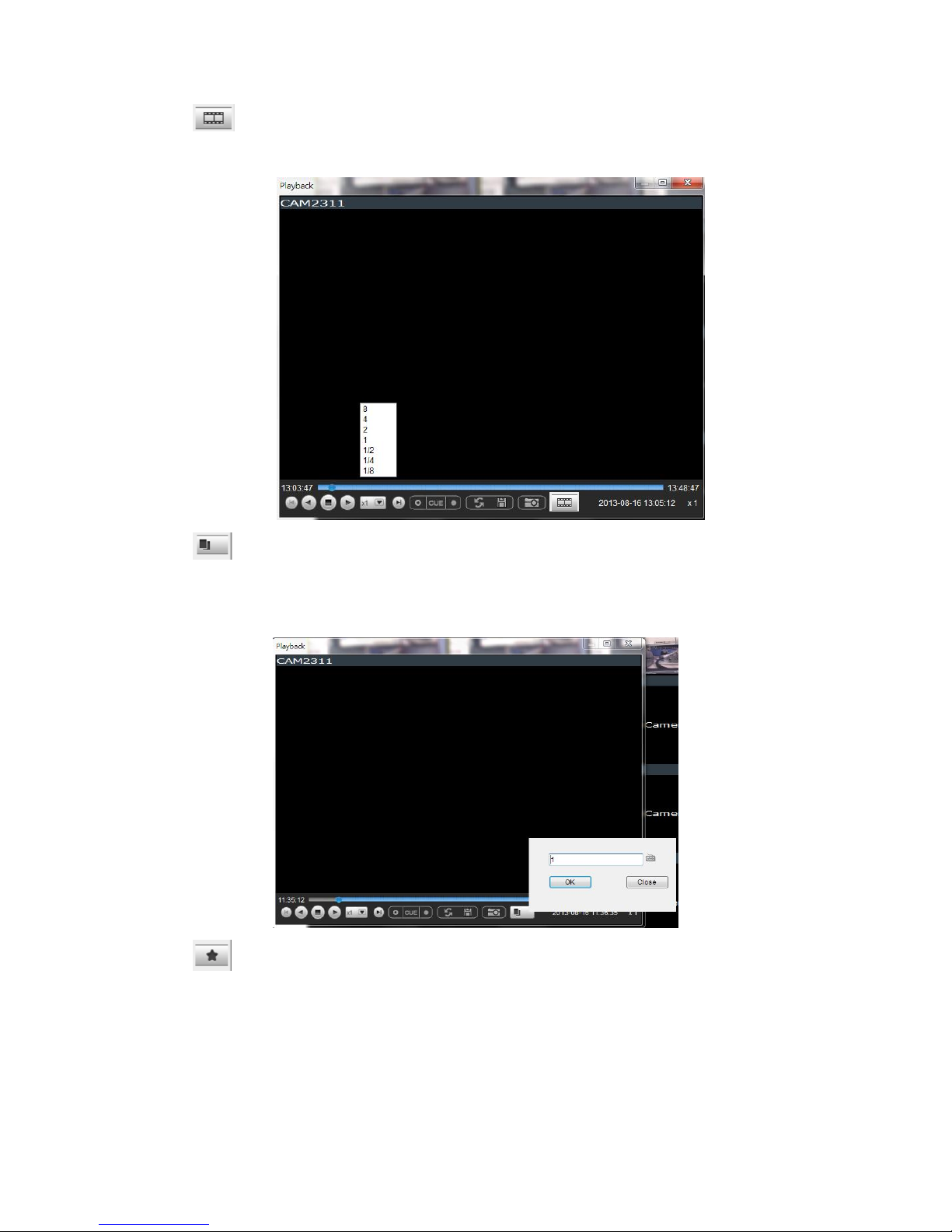
85
”Real Time” can be further defined to play in the speeds of 8x, 4x, 2x,
1x, 1/2x, 1/4x, and 1/8x.
“Frame By Frame” can be further defined to play in intervals from 1 to
15. Right click on the “Frame By Frame Mode” button to set the interval.
“Just Key Frame” can be further defined to play in intervals from 1 to
15. Right click on the “Just Key Frame Mode” button to set the interval.
Page 86

86
The following table explains the buttons:
Starts video playback.
Reverses video playback.
Stops video playback.
Jumps to the next segment.
Jumps to the previous segment.
Clears the cue-in and cue-out markers.
Set Cue-In marker for clip start
Set Cue-Out marker for clip end
Loop, continuous playback within Cue-In & Cue-Out
Enable / Disenable loop. Loop to continuous playback
within Cue-In & Cue-Out.
Saves video clips/Exports selected clips.
Snapshot
Real time mode
Frame by frame mode
Just key frame mode
Page 87

87
7.3.3. Manual Recording
When recording schedules are set, it may be necessary to manually record a
video stream, even when the schedule does not specify for recording. In this
case right-click the panel that recording is required on, and select Manual
Record > [5, 10 or 30 minutes] to activate the function. The camera will
record the stream for the amount of time specified.
7.3.4. Preset Pan
In cameras equipped with PTZ functionalities, presets set on the camera in the
PTZ Preset Settings will be available. To access the presets, right-click on the
panel containing the camera feed, and mouse-over Preset. The system will
respond with a list of presets configured on the camera. Selecting a preset will
pan the camera to the preset position.
7.3.5. Stream Selection
Video Streams can be selected by right-clicking the panel that playback is
required on, and then select Stream > Stream1/Stream2.
7.3.6. Image Settings
Camera image settings can also be accessed by right-clicking the panel
containing the camera video and selecting Others > Image Settings. This will
pull up the camera image settings menu.
Page 88

88
7.3.7. Video Ratio Adjustment
In most cases the video panel size will not match the size of the video feed
exactly. By default the VMS will stretch or shrink the video to fit the screen,
however you may also choose to preserve the original video ratio by right-
clicking the screen and selecting Others > Keep Video Length-Width Ratio. To
return to a stretched view, right-click the appropriate panel and choose Others
> Resize to Fit Window.
7.3.8. Inserting Overlays
The panel can be replaced with a user overlay.
Image Overlay
To overlay an image on top of a panel:
1. Right-click the panel and choose Others > Insert > Image. The system
will prompt you to choose an image file.
Page 89

89
2. Choose an image file, valid image types are JPEG, BMP, TIF, PNG. Click
Open to open the file.
3. The image will be displayed in the panel. Click the red X in the top-
right corner to close the image.
HTML Overlay
The HTML overlay function allows simple integration of web applications in the
VMS by replacing one or more panels of the screen with an active browsing
window. To overlay an HTML form or website on top of a panel:
1. Right-click the panel and choose Others > Insert > HTML.
2. In the field, enter a URL or the path containing the HTML form. You may
also choose to click Browse and choose an HTML file.
3. The HTML or website will be displayed in the panel. Click the red X in
the top-right corner to close the image.
Page 90
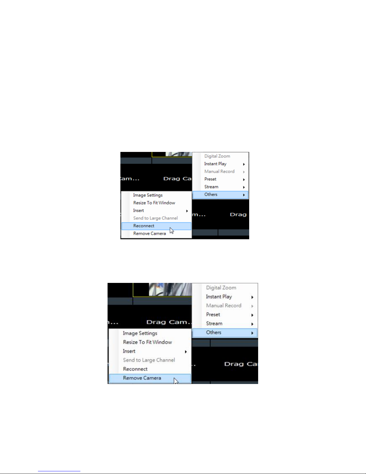
90
7.3.9. Send to Large Channel
Views in smaller divisions can be switched to the larger division. To perform this
action, right-click the panel corresponding to the camera and choose Others >
Send to Large Channel.
7.3.10. Reconnect
In some cases it may be necessary to manually reset the connection to a camera.
To perform this action, right-click the panel corresponding to the camera and
choose Others > Reconnect.
7.3.11. Remove the Camera
The Cameras can be removed by clicking Others > Remove Camera.
Page 91

91
7.3.12. Onscreen PTZ Control
Cameras equipped with Pan-Tilt-Zoom functionality can be controlled directly
within the VMS client software. These controls can be found within live views
whenever the cursor comes closer to the image panel, the onscreen PTZ control
will appear.
Pan and Tilt
The pan and tilt functionalities can be controlled with the directional pad.
Clicking the right or left arrow will pan the camera by one step in the direction
clicked. Clicking the up or down arrow will tilt the camera by one step in the
direction clicked. Clicking diagonal arrows will combine the pan and tilt action
of the adjacent arrows.
Zoom
The zoom on a camera can be controlled with the + and – buttons located inside
the direction pad. Pressing the + button will increase zoom distance by 1 step.
Pressing the – button will decrease zoom distance by one step.
Page 92

92
7.4. Full Screen View
7.4.1. Entering Full Screen View
From any view, you can switch to full screen mode by clicking on the full screen
button located above the main viewing window. Optionally you may also choose
to view a single frame in full screen mode by double clicking on the frame.
7.4.2. Exiting Full Screen Mode
To exit full screen mode, hit the ESC key on your keyboard.
Page 93

93
7.5. E-Maps
7.5.1. Adding E-Maps
1. Prepare layout drawings or a map of the area being surveyed.
2. Right click on E-Map Configuration in the E-map Explorer window, Click
Add under the E-map tab.
3. Click the Browse button to open a windows dialog. Select your map and
click the Open button. The drawing will be stored in the Server.
4. Enter a name for the map in the Map Name field.
5. Click Save. Once successfully added, an E-map node will appear.
Note: The E-Maps can also be edited by clicking Server > General Tasks > E-map
or Server Entry > Common Tasks > Common Server Tasks > E-map in the VMS
Console.
Page 94
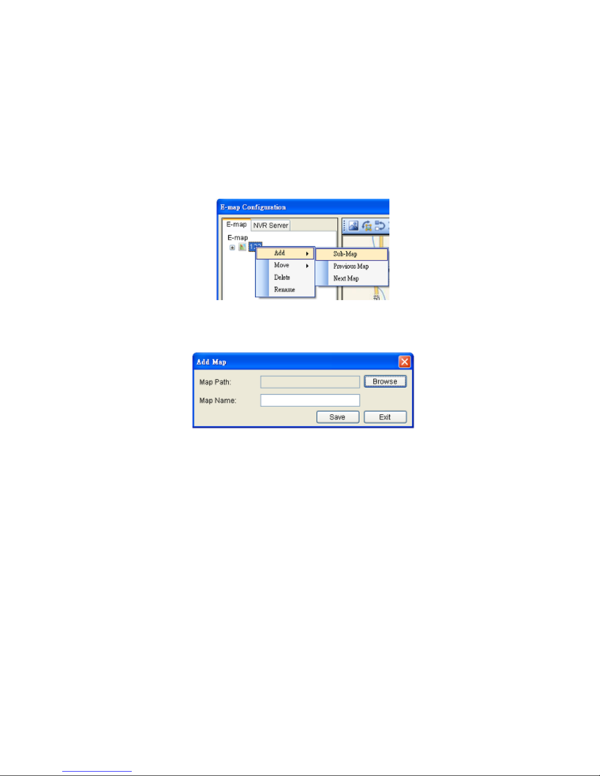
94
7.5.2. Adding Sub-Maps
Sub-maps can be used when separate areas within a large maps are complicated
enough to have their own specific layout.
1. Prepare layout drawings or a map of the area being surveyed.
2. In the E-map configuration screen, under the E-map tab, right-click the
node that you wish to add a sub-map to, and select Add > Sub-Map.
3. Click the Browse button to open a windows dialog. Select your map and
click the Open button. The drawing will be stored in the Server.
4. Enter a name for the map in the Map Name field.
5. Click Save. Once successfully added, an E-map node will appear as a
sub-node on the tree panel. A link with the sub-map name will also be
placed on the root map.
7.5.3. Adding Additional E-Maps
The typical E-map Add function will add new maps to the end of the list. You
may choose to add a map before or after an existing map by:
1. Prepare layout drawings or a map of the area being surveyed.
2. In the E-map configuration screen, under the E-map tab, right-click the
node which you want to add a map before or after. Choose Add >
Previous Map to add a map before the selected map, or choose Add >
Next Map to add a map after the selected map.
Page 95

95
3. Click the Browse button to open a windows dialog. Select your map and
click the Open button. The drawing will be stored in the Server.
4. Enter a name for the map in the Map Name field.
5. Click Save. Once successfully added, an E-map node will appear as in
the tree panel.
In the e-maps list, it is recommended to organize your e-maps in a logical order.
7.5.4. Changing E-Map Order
To re-order the e-maps you have added, right-click the node which you want to
move. Choose Move > Previous Map to move the selected map up the list, or
choose Move > Next Map to move the selected map down the list.
7.5.5. Renaming an E-Map
To rename an e-map you have added, right-click the node which you want to
delete and choose Rename. Enter a new name for the map and press enter to
save your changes.
7.5.6. Configuring an E-Map
1. Select an E-map entry clicking it.
2. Click the NVR Server tab to bring up a list of the cameras available for
placement.
Page 96

96
3. Drag and drop cameras to anywhere on the layout drawing. The map
may be moved by clicking and dragging the map, you may also zoom in
and out using the buttons above the map display.
4. Once a camera icon is placed, it may be rotated by clicking one of the
dotted corners of the camera icon.
5. You may save any time by clicking on the Save button located above the
map display.
7.5.7. Deleting an E-Map
To delete an e-map you have added, right-click the node which you want to
delete and choose Delete. This action will delete the node and any sub-nodes
from the map list.
7.5.8. Using the E-Map
Once E-Maps have been configured on the system, you can pull up an E-Map by
double clicking its entry in the E-Maps section of the Live View screen. This will
open the E-Map in a floating window.
Double-clicking on any camera icon that has been placed on the map will bring a
live view screen for this camera.
Page 97

97
You can choose to do instant playback, snapshot capture and alarm management
by right clicking on the live view screen.
The camera icons that have been placed on the map will blink if there is an
alarm associated with it. Double-click on any camera icon to bring up a live
video feed in a popup window.
There are also a few buttons associated with this view:
Zoom Out: Located at the bottom mid-left. This button shrinks the background
map display.
Zoom In: Located at the bottom mid-right. This button enlarges the background
map display.
Arrows: Located on the top left. Use the arrow keys to move from map levels.
Up to 4 cameras can be popped up at the same time, when there’s any alarm
triggered. If there’s a fifth alarm occurs, the VMS will close the oldest popup
window and show the new popup.
Page 98

98
Chapter 8. Server Setup
This section deals with Server setup procedures.
8.1. Server Basic Functions
When you are logged into a domain, the Servers configured on the domain will
appear in the Device Browser area. The icon by the Server shows the current
connection state of the Server.
Icon
Meaning
The Server cannot be reached
The Server can be reached, but the
user is not logged in
The user is logged in to the Server
8.1.1. Logging into a Server
1. Right-click the server entry in the Device Browser window to bring up the
options popup.
2. Highlight and click the Login option. As long as the credentials supplied
at the beginning of the session are correct, you will be automatically
logged in.
8.1.2. Logging out of a Server
1. Right-click the server entry in the Device Browser window to bring up the
options popup.
2. Highlight and click the Logout option to bring up the logout dialog box.
3. Press the Yes button to logout.
Note: Logging out of the domain server will cause the client to logout
completely.
Page 99

99
8.1.3. Renaming a Server
You must be connected to a server as an admin to rename it. To rename a
Server:
1. Right-click the server entry in the Device Browser window to bring up the
options popup.
2. Highlight and click the Configuration > Rename option.
3. Type the new name in the box that appears.
8.1.4. Viewing Server and Client Information
1. Right-click the server entry in the Device Browser window to bring up the
options popup.
2. Highlight and click the Configuration > About option to bring up the
About dialog box.
3. Click OK when finished viewing.
Note: The Server and Client information can also be viewed by clicking Others >
Other Tasks > About in the VMS Console.
Page 100
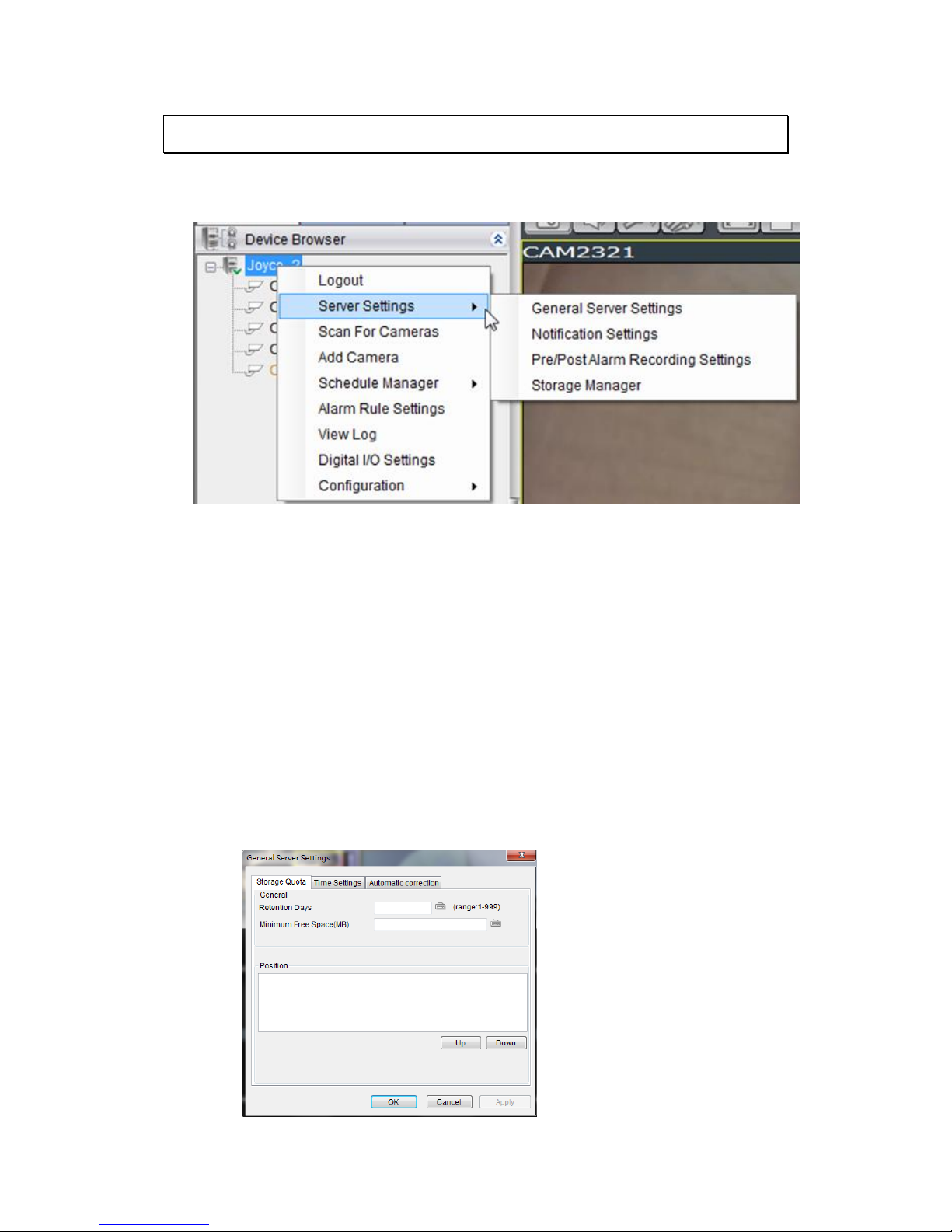
100
8.2. Server Settings
The following sections deal with Server settings that can be configured under
the Server Settings menu.
8.2.1. General Server Settings
Server general setup procedures involve configuring both storage and server
time settings. To perform Server general setup:
Right-click the Server entry in the Device Browser highlight and click the Server
Settings > General Server Settings option. A tabbed window will appear
providing the following configuration tabs: Storage Quota, Time Settings, and
Automatic Correction.
1. Storage Quota
 Loading...