


Network IR PTZ Camera
User Manual
Ver. 1.0
002C83XZZ1A3


1
All Rights Reserved © Surveon Technology 2017
Copyright Statement
No part of this publication may be reproduced, transmitted, transcribed, stored in a retrieval
system, or translated into any language or computer language, in any form or by any means,
electronic, mechanical, magnetic, optical, chemical, manual or otherwise, without the prior written
consent of Surveon Technology Inc.
Disclaimer
Surveon Technology makes no representations or warranties with respect to the contents hereof
and specifically disclaim any implied warranties of merchantability or fitness for any particular
purpose. Furthermore, Surveon Technology reserves the right to revise this publication and to
make changes from time to time in the content hereof without obligation to notify any person of
such revisions or changes. Product specifications are also subject to change without notice.
Trademarks
Surveon and Surveon logo are trademarks of Surveon Technology Inc. Other names prefixed with
“SMR” and “EMR” are trademarks of Surveon Technology Inc.
Microsoft Windows and Windows are registered trademarks of Microsoft Corporation.
Linux is a trademark of Linux Torvalds.
Solaris and Java are trademarks of Sun Microsystems, Inc.
All other names, brands, products or services are trademarks or registered trademarks of their
respective owners.

2
Revision History
Description
Date
1.0
Initial release
October 2017

3
Table of Contents
1. Overview ................................................................................................................................. 7
2. Technical Specification ............................................................................................................ 8
2.1
Package Contents .................................................................................................. 10
2.2
Dimensions ............................................................................................................ 11
2.3
Connectors ............................................................................................................ 12
3. Camera Cabling .................................................................................................................... 13
3.1
Connectors ............................................................................................................ 14
3.2
Ethernet Cable Connection .................................................................................... 14
3.3
Audio / Alarm I/O & RS-485 Connection ................................................................ 14
4. System Requirements ........................................................................................................... 16
5. Access Camera ................................................................................................ ..................... 16
6. Setup Video Resolution ......................................................................................................... 20
7. Configuration Files Export / Import ........................................................................................ 22
8. Tech Support Information ...................................................................................................... 23
8.1
Deleting the Exisiting DCViewer ............................................................................. 23
8.2
Setup Internet Security........................................................................................... 24
9. Menu Tree ............................................................................................................................. 25
9.1
Home Page ............................................................................................................ 26
9.1.1
Function Items on Home Page ....................................................................... 26
9.2
System ................................................................................................................... 31
9.2.1
System ........................................................................................................... 31
9.2.2
Security .......................................................................................................... 33
9.2.2.1 User ........................................................................................................ 33
9.2.2.2 HTTPS ................................................................................................... 36
9.2.2.3 IP Filter ................................................................ ................................... 38
9.2.2.4 IEEE 802.1X ........................................................................................... 40
9.2.3
Network .......................................................................................................... 41
9.2.3.1 Basic ...................................................................................................... 41
9.2.3.2 QoS ........................................................................................................ 45
9.2.3.3 SNMP ..................................................................................................... 46
9.2.3.4 UPnP ...................................................................................................... 48
9.2.4
DDNS ............................................................................................................. 49
9.2.5
Mail ................................................................................................................ 49
9.2.6
FTP ................................................................................................................ 50
9.2.7
HTTP.............................................................................................................. 50
9.2.8
Events (Alarm Settings) .................................................................................. 51
9.2.8.1 Application .............................................................................................. 51
9.2.8.2 Motion Detection ..................................................................................... 56
9.2.8.3 Network Failure Detection ...................................................................... 62
9.2.8.4 Periodical Event ...................................................................................... 64
9.2.8.5 Manual Trigger ....................................................................................... 67
9.2.8.6 Audio Detection ...................................................................................... 71
9.2.9
Storage Management ..................................................................................... 75
9.2.9.1 SD Card.................................................................................................. 75
9.2.9.2 Network Share (NAS) ............................................................................. 77
9.2.10
Recording ....................................................................................................... 79
9.2.11
Schedule ........................................................................................................ 80
9.2.12
File Location (Snapshots and Web Recording) ............................................... 81
9.2.13
View Information ............................................................................................ 81
9.2.13.1 Log File ........................................................................................... 81
9.2.13.2 User Information ............................................................................. 82
9.2.13.3 Parameters ..................................................................................... 82
9.2.14
Factory Default ............................................................................................... 83
9.2.15
Software Version ............................................................................................ 83
9.2.16
Software Upgrade .......................................................................................... 84
9.2.17
Maintenance................................................................................................... 85
9.3
Streaming .............................................................................................................. 86

4
9.3.1
Video Format (Video Resolution and Rotate Type) ......................................... 87
9.3.2
Video Compression ........................................................................................ 89
9.3.3
Video OCX Protocol ....................................................................................... 90
9.3.4
Video Frame Rate .......................................................................................... 90
9.3.5
Audio (Audio Mode and Bit Rate Settings) ...................................................... 91
9.4
Camera ................................................................................................ .................. 93
9.4.1
Exposure ........................................................................................................ 94
9.4.2
White Balance ................................................................................................ 95
9.4.3
Picture Adjustment ......................................................................................... 97
9.4.4
IR Function ..................................................................................................... 98
9.4.5
Noise Reduction ........................................................................................... 100
9.4.6
Profile ........................................................................................................... 101
9.4.7
Backlight ...................................................................................................... 102
9.4.8
Digital Zoom ................................................................................................. 102
9.4.9
WDR ............................................................................................................ 102
9.4.10
Image Stabilizer ........................................................................................... 103
9.4.11
TV System.................................................................................................... 104
9.5
PTZ ...................................................................................................................... 105
9.5.1
Preset........................................................................................................... 105
9.5.2
Cruise........................................................................................................... 106
9.5.3
Auto Pan ...................................................................................................... 107
9.5.4
Sequence ..................................................................................................... 108
9.5.5
Home Function ............................................................................................. 109
9.5.6
Tilt Range ..................................................................................................... 110
9.5.7
Privacy Mask ................................................................................................ 110
9.5.8
PTZ Setting .................................................................................................. 112
2.5.9 RS485 .......................................................................................................... 114
9.6
Logout .................................................................................................................. 114
Appendix A: Install UPnP Components ........................................................................................ 115
Appendix B: IP Addresses from Decimal to Binary ....................................................................... 116
Appendix C: Video Resolution ..................................................................................................... 117
WDR OFF ............................................................................................................................. 117
Quad Streams- 4M Models Only .................................................................................... 117
Quad Streams- 3M Models Only .................................................................................... 125
Quad Streams- 4M/3M/2M Models ................................................................................ 128
Triple Streams- 4M Models Only ................................................................................... 139
Triple Streams- 3M Models Only ................................................................................... 141
Triple Streams- 4M/3M/2M Models ................................................................................ 142
Dual Streams- 4M Models Only ..................................................................................... 146
Dual Streams- 3M Models Only ..................................................................................... 146
Dual Streams- 4M/3M/2M Models.................................................................................. 146
Single Stream- 4M/3M/2M Models ................................................................................. 147
WDR ON- 2 Shutter Mode .................................................................................................... 148
Triple Streams- 4M Models Only ................................................................................... 148
Triple Streams- 3M Models Only ................................................................................... 150
Triple Streams- 4M/3M/2M Models ................................................................................ 151
Dual Streams- 4M Models Only ..................................................................................... 155
Dual Streams- 3M Models Only ..................................................................................... 155
Dual Streams- 4M/3M/2M Models.................................................................................. 155
Single Stream- 4M/3M/2M Models ................................................................................. 156
WDR ON- 3 Shutter Mode .................................................................................................... 157
Triple Streams- 4M Models Only ................................................................................... 157
Triple Streams- 3M Models Only ................................................................................... 159
Triple Streams- 4M/3M/2M Models ................................................................................ 160
Dual Streams- 4M Models Only ..................................................................................... 164
Dual Streams- 3M Models Only ..................................................................................... 164
Dual Streams- 4M/3M/2M Models.................................................................................. 164
Single Stream- 4M/3M/2M Models ................................................................................. 165
5
Safety Precautions
Electric Shock Warning
This equipment may cause electric shocks if not handled properly.
Access to this equipment should only be granted to trained operators and maintenance
personnel who have been instructed of, and fully understand the possible hazardous
conditions and the consequences of accessing non-field-serviceable units such as the
power supplies.
The system must be unplugged before moving, or in the even that it becomes damaged.
Reliable Grounding
Particular attention should be given to prepare reliable grounding for the power supply
connection. It is suggested to use a direct connection to the branch circuit. Check for proper
grounding before powering on the device.
Overloading Protection
The device should be installed according to specifications. Provide a suitable power source with
electrical overload protection. Do not overload the AC supply branch circuit that provides
power to the device.
ESD Precautions
Please observe all conventional anti-ESD methods while handling the device. The use of a
grounded wrist strap and an anti-static work pad are recommended. Avoid dust and debris in
your work area.

6
Device Installation/Site Selection
The device should be installed according to specifications. This device should be operated at a
site that is:
Clean, dry, and free of excessive airborne particles.
Well-ventilated and away from heat sources such as direct sunlight and radiators.
Clear of vibration or physical shock.
Away from strong electromagnetic fields produced by other devices.
Available with properly grounded wall outlet for power. In regions where power sources
are unstable, apply surge suppression.
Available with sufficient space behind the device for cabling.
Never install or use, unless waterproof or dust-resistant is listed as a feature, the device in
the following locations:
Areas where chemicals are used.
Areas where dust, debris, or pollen is in excess.
Areas where corrosive gas, sea water or high humidity is present.
Areas where steam vapor or flammable environments is generated.
Areas where radiation, X-rays, strong electric waves, or magnetism is generated.
Areas outside of the allowable ambient operating temperature range.
Areas subject to impact or rigorous vibration.

7
1. Overview
With the latest encoding technology and built-in IR LEDs, Network IR PTZ
Camera presents strong HDR and high sensitivity performance. The camera is
capable of capturing high resolution images during daylight hours and even in
pitch-black darkness.
At night, or in any environment where there is low/zero lighting, Network IR PTZ
Camera is able to provide effective illumination to the objects up to 200 meters
away, and also deliver crystal clear and image with high quality up to 30x optical
zoom lens in long distance.
With delicate mechanism design, Network IR PTZ Camera features Servo
Feedback technology, which makes the camera precisely return to the previous
position without stalling, and ensures the target monitoring region is fully
secured. IP66 International standard is also guaranteed for outdoor installation.
Furthermore, combining 0 downtime power switching technology, the camera
ensures smooth streaming without sudden power-loss.

8
2. Technical Specification
Technical Specification
CAM6371LZ
CAM6571LZ
Camera
Image Sensor
1/2.8” Megapixel Sony
Progressive CMOS
1/3” Megapixel Progressive
CMOS
Lens
f4.3 – 129mm autofocus lens, F1.6(wide) – F4.7(tele)
SNR
50dB
WDR
High Dynamic Range (120dB)
Day/Night ICR
Yes
IR LED
200M
100M
Min. Illumination
0.005lux@F1.6(B/W)
0.02lux@F1.6(Color)
0 lux@F1.6(B/W with IR)
0.02lux@F1.6(Color)
Iris Control
Automatic/Manual IRIS control
Shutter Time
1/1 ~ 1/10,000s
Viewing Angle
68.7° (Wide); 2.6° (Tele)
60.8° (Wide); 2.3° (Tele)
Camera Angle
Adjustment
Pan: 360°endless, 0.1° ~ 280 /s
Tilt: -20°~+200°,0.1° ~ 300°/s
Pan/Tilt/Zoom
Functionalities
-180°Horizontal Instant Flip
-256 preset positions
-Preset position auto scanning
-Sequence up to 8, Auto Pan up to 4, Cruise up to 8
-30x optical zoom
-10x digital zoom
Video
Video
Compression
MJPEG & H.264 Baseline/Main and High profile
Resolution
Up to 2M (1920 x 1080)
Up to 4M (2560 x 1440)
Frame Rate
60 fps at 1080P (1920x1080)
60 fps at SXGA (1280x1024)
60 fps at 720P (1280x720))
60 fps at D1 (720x480)
60 fps VGA (640x480)
60 fps QVGA (320x240)
30 fps at 4M (2560x1440)
60 fps at 1080P (1920x1080)
60 fps at SXGA (1280x1024))
60 fps at D1 (720x480)
60 fps VGA (640x480)
60 fps QVGA (320x240)
Video Stream
Dual stream at H.264 and MJPEG simultaneously
Bit Rate
64K ~ 10Mbps, VBR, CBR, controller frame rate and quality
Video Control
-AGC(Auto Gain Control), AWB(Auto White Balance), BLC(Back
Light Compensation), 2D/3D Noise Reduction, Electrical Image
Stabilizer (EIS), Image adjustment, Privacy zone:On/Off(20zones)
Intelligent Video
Motion Detection
Video Jack
N/A
Audio
Built-in MIC
N/A
Audio
Compression
G.711/G.726/AAC

9
Audio
Input/Output
Two-Way Audio
I/O and
Event
Managem
ent
Alarm In
4, terminal block
Alarm Out
2, terminal block
Video Buffer
N/A
Event Action
Send snapshot or video clip by FTP or email, record to local
storage, trigger DO
Network
Supported
Protocols
IPv4/v6, TCP/IP, UDP, RTP, RTSP, HTTP, HTTPS, ICMP, FTP,
SMTP, DHCP, PPPoE, UPnP, IGMP, SNMP, QoS, ONVIF, ARP
Ethernet
RJ-45, 1Gbps Ethernet
System
Local Storage
SD support
RS-485
N/A
USB
N/A
SDK
Surveon SDK 2.0
Viewing
System
OS
Microsoft Windows 7/8 or above
Browser
Internet Explorer (10.0+)/Firefox/Safari
Software
Surveon BVR v3.4 or above
General
Temperature
Operation:-40°C~50°C(-40°F~122°F)
Humidity
10%~90%, No Condensation
Power
802.3at PoE+ / AC 24V± 20%
Power
Consumption
Max. 44.5W (with IR & Heater on)
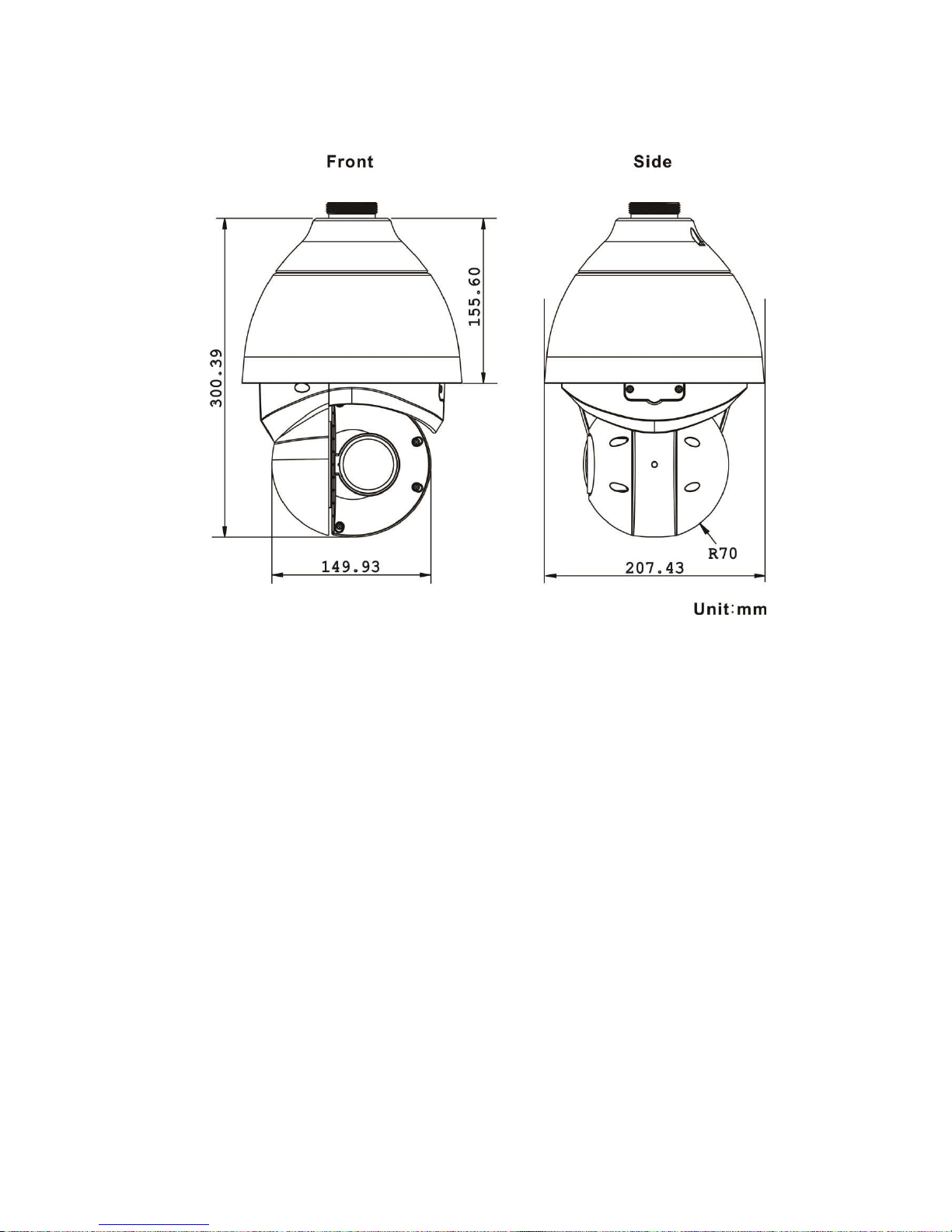
Dimension
(WxHxD)
ø207.43 x 300.39mm
Weight
Net: 3.8kg / Gross: 5.0kg
Certification
CE/FCC/RoHS/IP66
Warranty
2 years
10
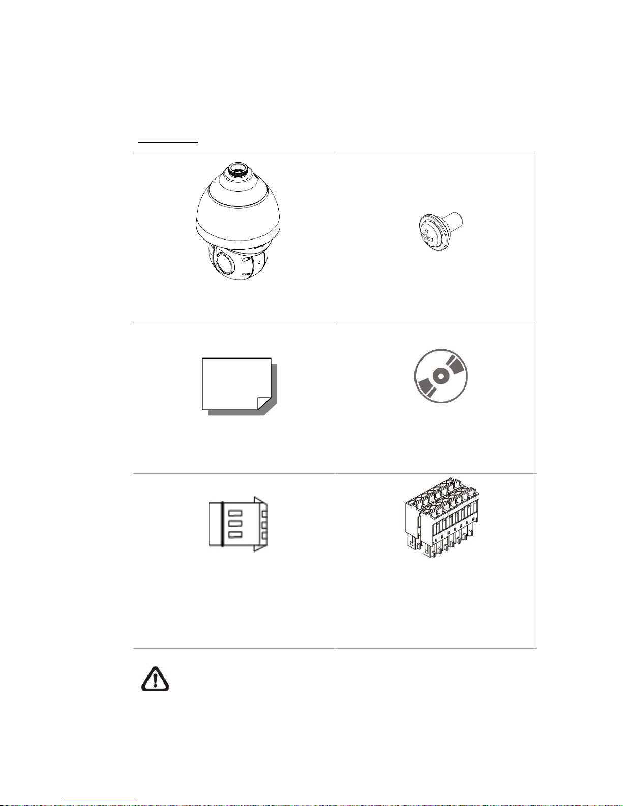
2.1
Package Contents
Please check the box contains the items listed here. If any item is missing or has defects,
DO NOT install or operate the product and contact the dealer for assistance.
Outdoor
Network IR PTZ
Camera
M4 Security Screw with
Rubber
Quick Guide
CD
3-Pin
Power
Terminal
Block
14-Pin Alarm/Audio
I/O Terminal
Block
NOTE: To purchase power adaptor, please contact the camera
manufacturer for further information.
11
2.2
Dimensions
12
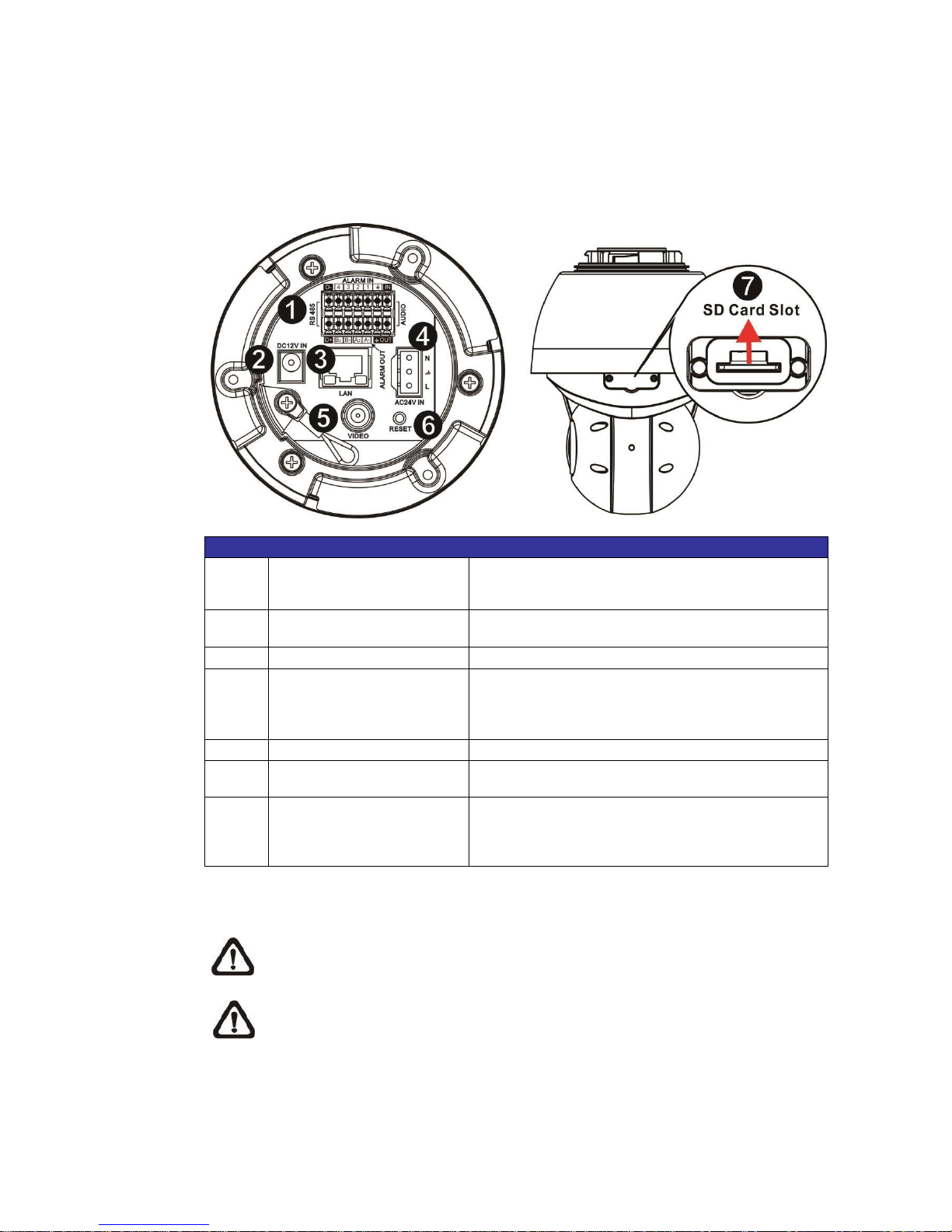
2.3
Connectors
Refer to the diagrams below for the positions of the reset button and various
connectors of the camera. Definition of the reset button and the connectors are
given as follow.
No.
Connector
Definition
1
Audio/Alarm I/O & RS485
Connector *
Audio/Alarm I/O & RS-485 connection
2
Power Connector
(DC12V)
DC12V power connection
3
RJ-45 Port **
IEEE 802.3at (PoE+) 4-Pair 60W only
4
Power
Connector
(AC24V / DC2848V)
AC24V / DC28-48V power connection
5
BNC
For analog video output
6
Reset Button
Press the button with a proper tool for at least 20
seconds to restore the system.
7
SD Card Slot
Insert the SD card into the card slot to store
videos and snapshots. Do not remove the SD
card when
the camera is powered on.
*Do NOT connect external power supply to the alarm I/O connector of the camera.
**Please contact the manufacturer for compatible PoE injector.
NOTE: DC12V power jack and AC24V / DC28-48V power connector
cannot be used at the same time in case of unexpected damage.
NOTE: It is not recommended to record with the SD card for 24/7
continuously, as it may not be able to support long term continuous data
read/write. Please contact the manufacturer of the SD card for information
regarding the reliability and the life expectancy.
13
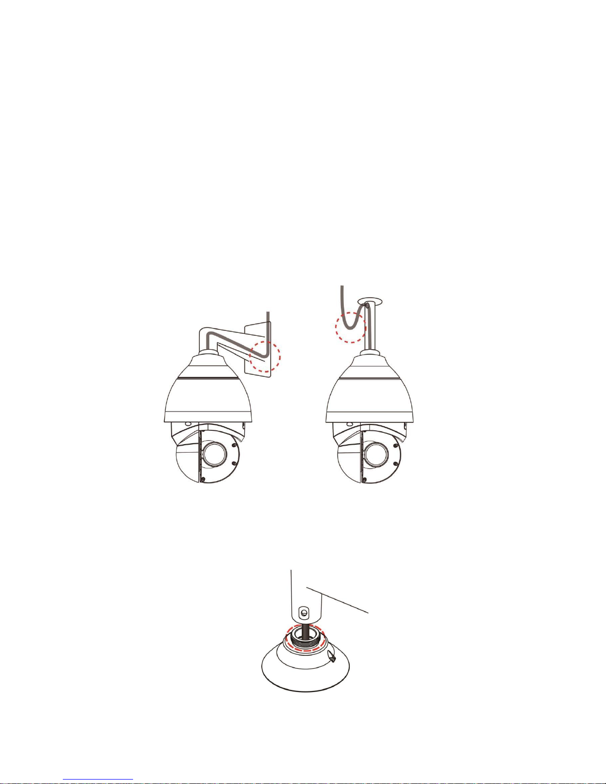
3. Camera Cabling
The outdoor models are being IP66-rated to prevent water from entering the
camera. However, water might still enter the camera if it is being improperly
installed. Please make sure the warnings below are strictly followed when
installing the camera.
Place all cables and the adaptor in dry and well-waterproofed
environments, e.g. waterproof boxes. The purpose is to prevent moisture
accumulation inside the camera and moisture penetration into cables.
While running cables, slightly bend the cables to a U-shaped curve to
make a low point (as demonstrated in the figures below). The purpose is
to prevent water from entering the camera along the cables from above.
The cable entry hole of the outdoor mounting kit (indicated in the figure
below) needs to be sealed with thread seal tape to avoid water from
entering the camera.
14
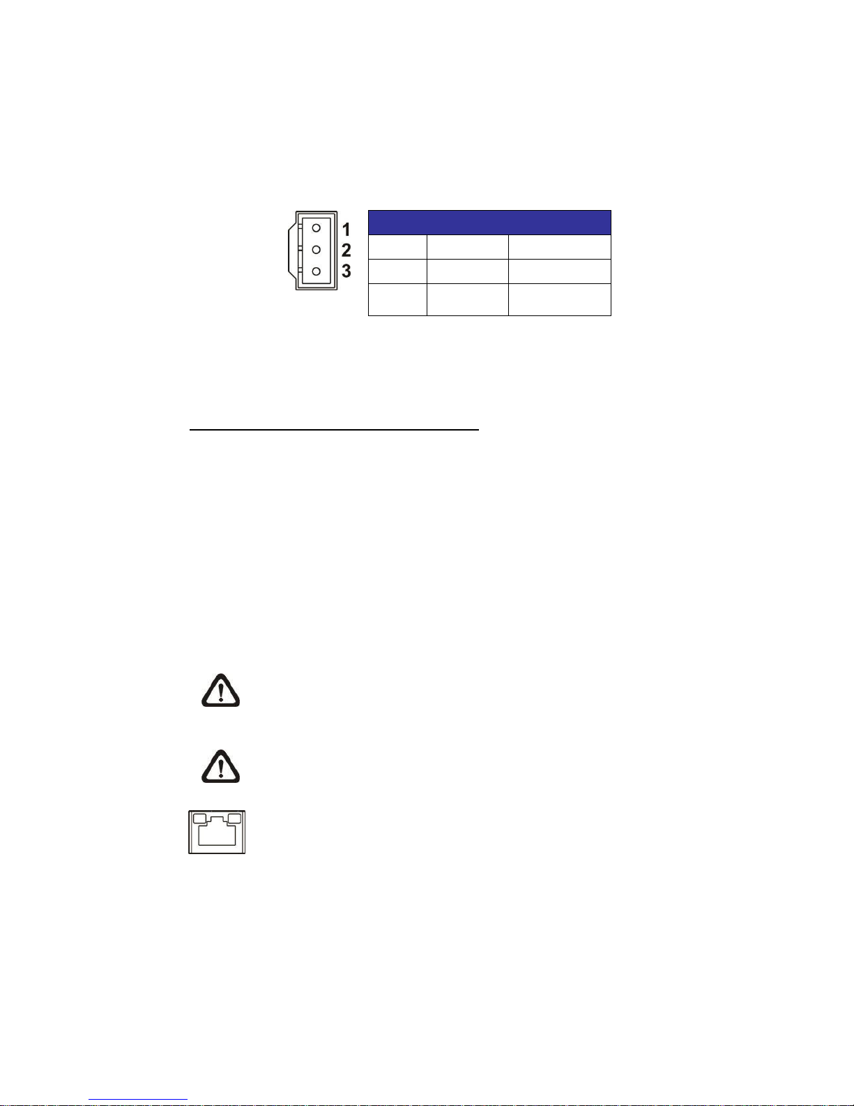
3.1
Connectors
To power up the camera, connect the DC12V or AC24V / DC28-48V power
adaptor to the power connector of the camera and the power outlet. Refer to the
diagram and pin definition below for AC24V / DC28-48V power connection.
Pin
Definition
1
AC24V N
DC28-48V +
2
GND
-
3
AC24V L
DC28-48V -
Alternatively, users can use an Ethernet cable and connect it to the RJ-45 port
of the camera and an IEEE 802.3at (PoE+) 4-Pair 60W switch.
Zero Downtime Power Switching (ZDT)
When users connect DC12V power jack and the RJ-45 port at the same time,
the power input comes from the DC12V connector. If the DC12V power source
fails, the camera will switch power input seemly to the RJ-45 port until the
DC12V power source is restored.
3.2
Ethernet Cable Connection
To connect one end of the Ethernet cable to the RJ-45 connector of the camera,
and plug the other end of the cable to the network switch or PC.
NOTE: In some cases, Ethernet crossover cable might be needed when
connecting the camera directly to the PC.
NOTE: Check the status of the link indicator and activity indicator LEDs.
If the LEDs are unlit, please check the LAN connection.
Green Link Light indicates good network connection.
Orange Activity Light flashes for network activity
indication.
3.3
Audio / Alarm I/O & RS-485 Connection
Please refer to the diagram and pin definition tables below for audio/alarm I/O &
RS-485 connection.

15
Pin
Definition
Pin
Definition
Pin
Definition
Pin
Definition
1
Audio In
5
Alarm In 1
9
Alarm In 3
13
RS-485 D-
2
Audio Out
6
Alarm Out A1
10
Alarm Out B1
14
RS-485 D+
3
GND (Alarm
I/O & RS-485)
7
Alarm In 2
11
Alarm In 4
4
GND
(Audio I/O)
8
Alarm Out A2
12
Alarm Out B2

16
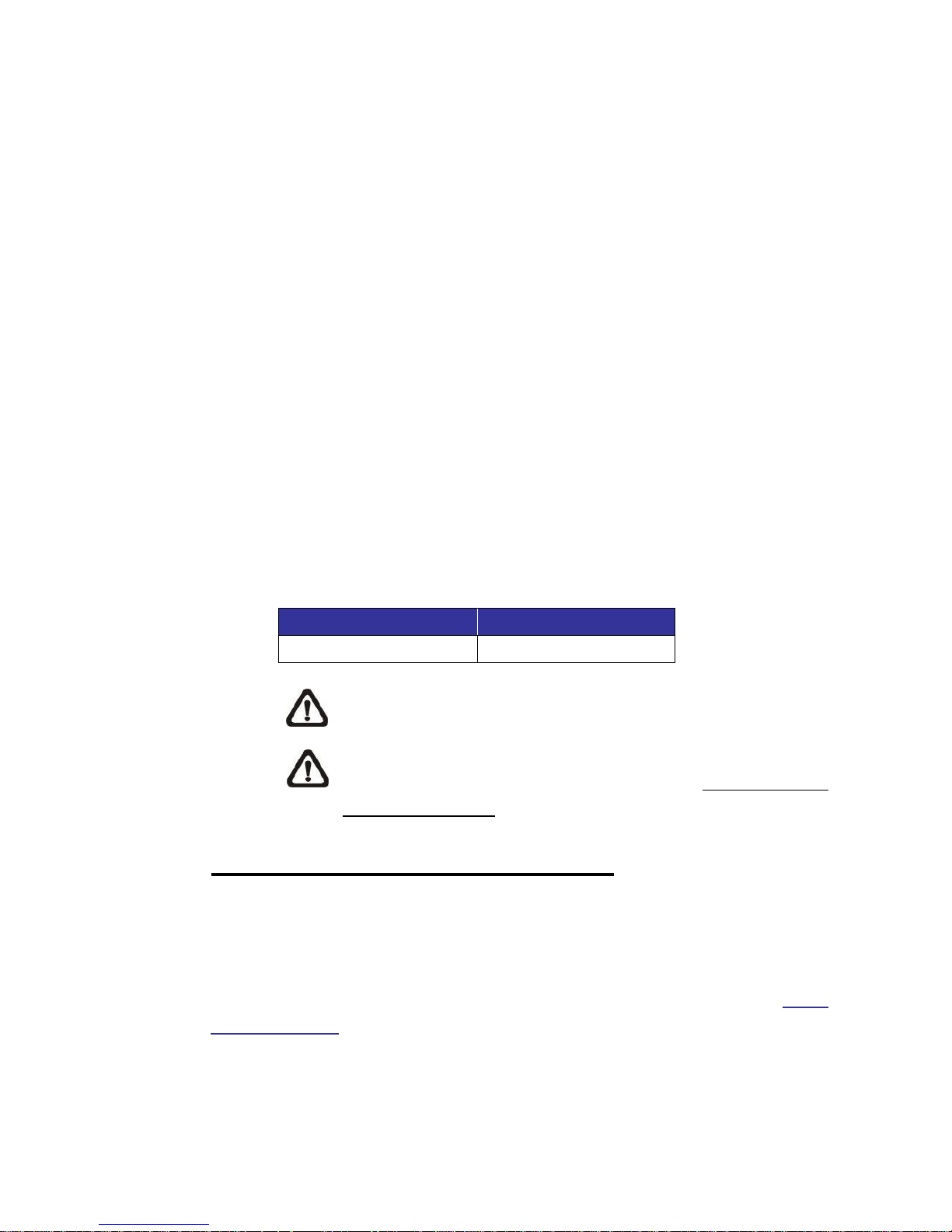
4. System Requirements
To perform the camera via web browser, please ensure the PC is in good
network connection, and meet the system requirement as described below.
Items
System Requirement
Personal Computer
Minimum :
1. Intel® CoreTM i5-2430M @ 2.4 GHz
2. 2 GB RAM or more
Recommended :
3. Intel® CoreTM i7-870 @ 2.93 GHz
4. 8 GB RAM
Operating System
Windows VISTA / Windows XP / Windows 7
Web Browser
Microsoft Internet Explorer 10.0 or later
(recommended) Firefox (32-bit)
Safari
Network Card
10Base-T (10 Mbps) or 100Base-TX (100 Mbps) or
1000Base-T operation
Viewer
ActiveX control plug-in for Microsoft IE
Apple QuickTime 7.7.7 or Before for Firefox
NOTE: The ITE is to be connected only to PoE networks without routing
to the outside plant or equivalent description.
5. Access Camera
For initial access to the camera, users can search the camera through the
installer program: DeviceSearch.exe, which can be found in “Device Search”
folder in the supplied CD.
Accessing the Camera by Device Search Software
Step 1: Double click on the program Device Search.exe.
Step 2: After its window appears, click on the <Device Search> button on the
top. All the finding IP devices will be listed in the page.
Step 3: Find the camera in the list by its IP address and click on it. The default
IP address of the camera is: 192.168.0.250.
Step 4: The default IP address of the camera may not be in the same LAN as
17
the IP address of the PC. If so, the IP address of the camera needs to
be changed. Right click on the camera and click <Network Setup>.
Meanwhile, record the MAC address of the camera, for future
identification.
Step 5: The <Network Setup> page will come out. Select <DHCP> and click
<Apply> down the page. The camera will be assigned with a new IP
address.
Step 6: Click <OK> on the Note of setting change. Wait for one minute to re-
search the camera.
Step 7: Click on the <Device Search> button to re-search all the devices. Find
the camera in the list by its MAC address. Then double click or right
click and select <Browse> to access the camera directly via a web
browser.
Step 8: A prompt window requesting for default username and password will
appear. Enter the default username and password shown below to
login to the camera.
Login ID
Password
Admin
1234
NOTE: ID and password are case sensitive.
NOTE: It is strongly advised that administrator’s password be
altered for the security concerns. Refer to the Network IR PTZ
Camera Menu Tree in the supplied CD for further details.
Installing DCViewer Software Online
For the initial access to the camera, a client program, DCViewer, will be
automatically installed to the PC when connecting to the camera.
If the web browser doesn’t allow Viewer installation, please check the Internet
security settings or ActiveX controls and plug-ins settings (refer to section Setup
Internet Security) to continue the process.
The Information Bar (just below the URL bar) may come out and ask for
permission to install the ActiveX Control for displaying video in browser.
Right click on the Information Bar and select <Install ActiveX Control…> to allow

18
the installation. A security warning window will pop up. Click on <Install> to carry
on software installation.
The download procedure of DCViewer software is specified as follows.
Step 1: In the DCViewer installation window, click on <Next> to start the
installation.
Step 2: A status bar will be displayed to show the installation progress.
After the installation is completed, click on <Finish> to exit the
installation process.
Step 3: Click on <Finish> to close the DCViewer installation page.
19
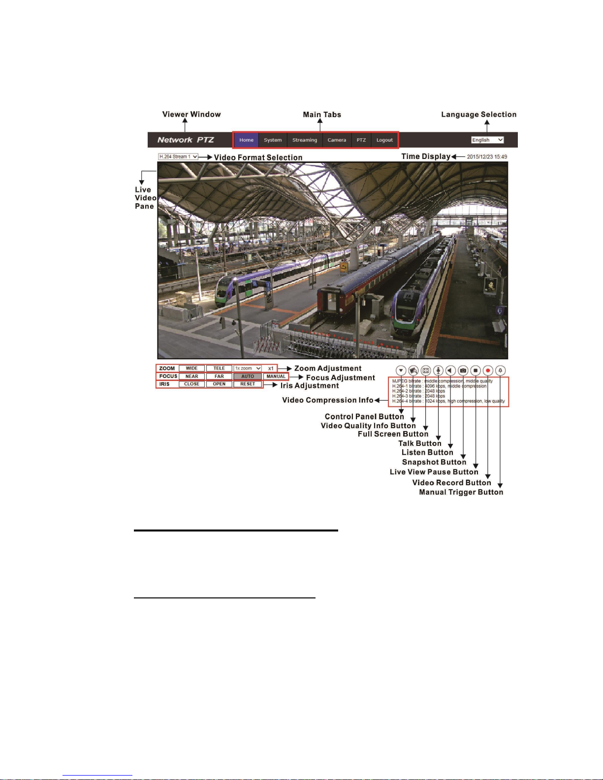
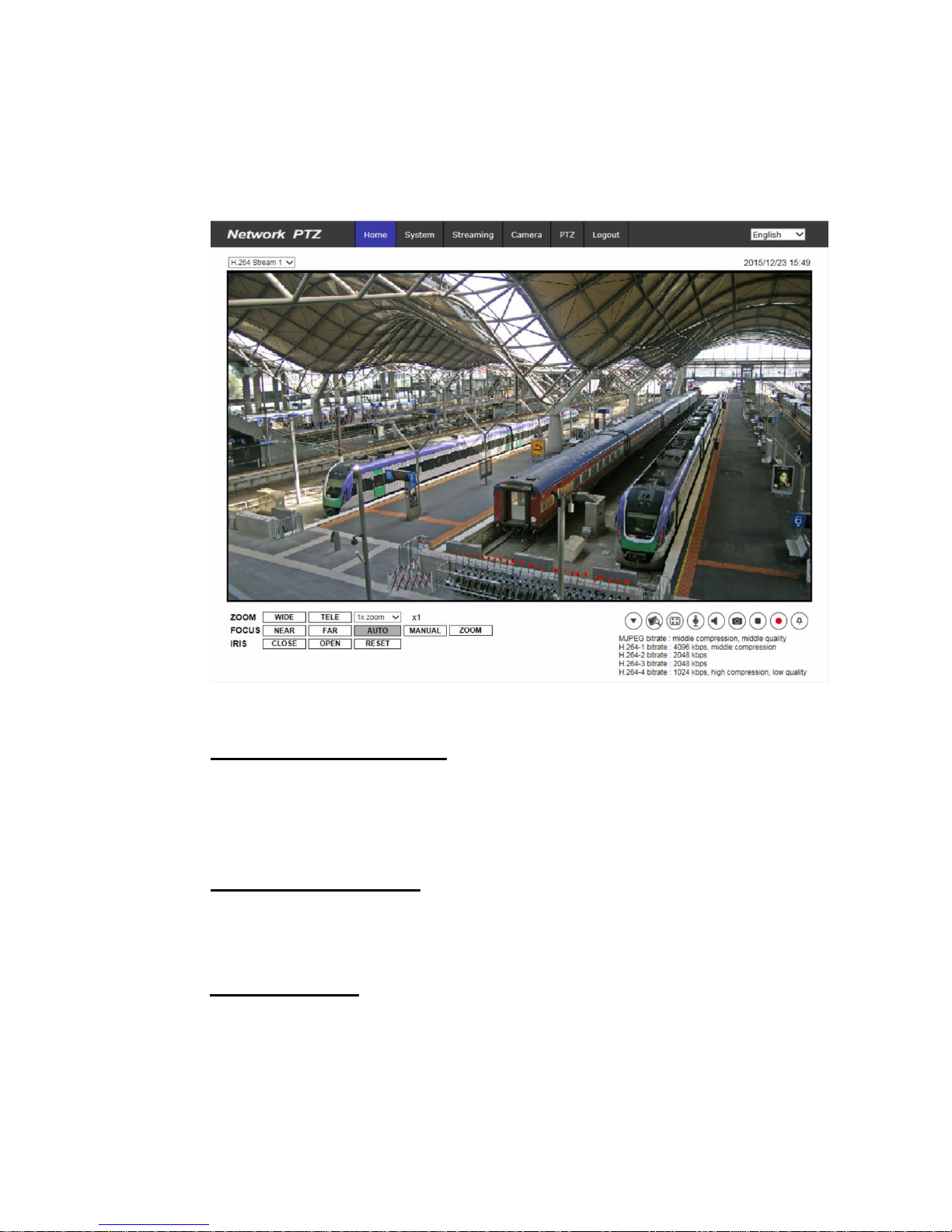
Once the Viewer is successfully installed, the Home page of the camera will be
shown as the figure below.
Zoom and Focus Adjustment
The live image will be displayed on the Home page when the
camera is successfully accessed. If zoom or focus is not at the desired position,
please use the function buttons on the Home page for adjustment. Refer to the
Network IR PTZ Camera Menu Tree in the supplied CD for more details about
the function buttons.
20
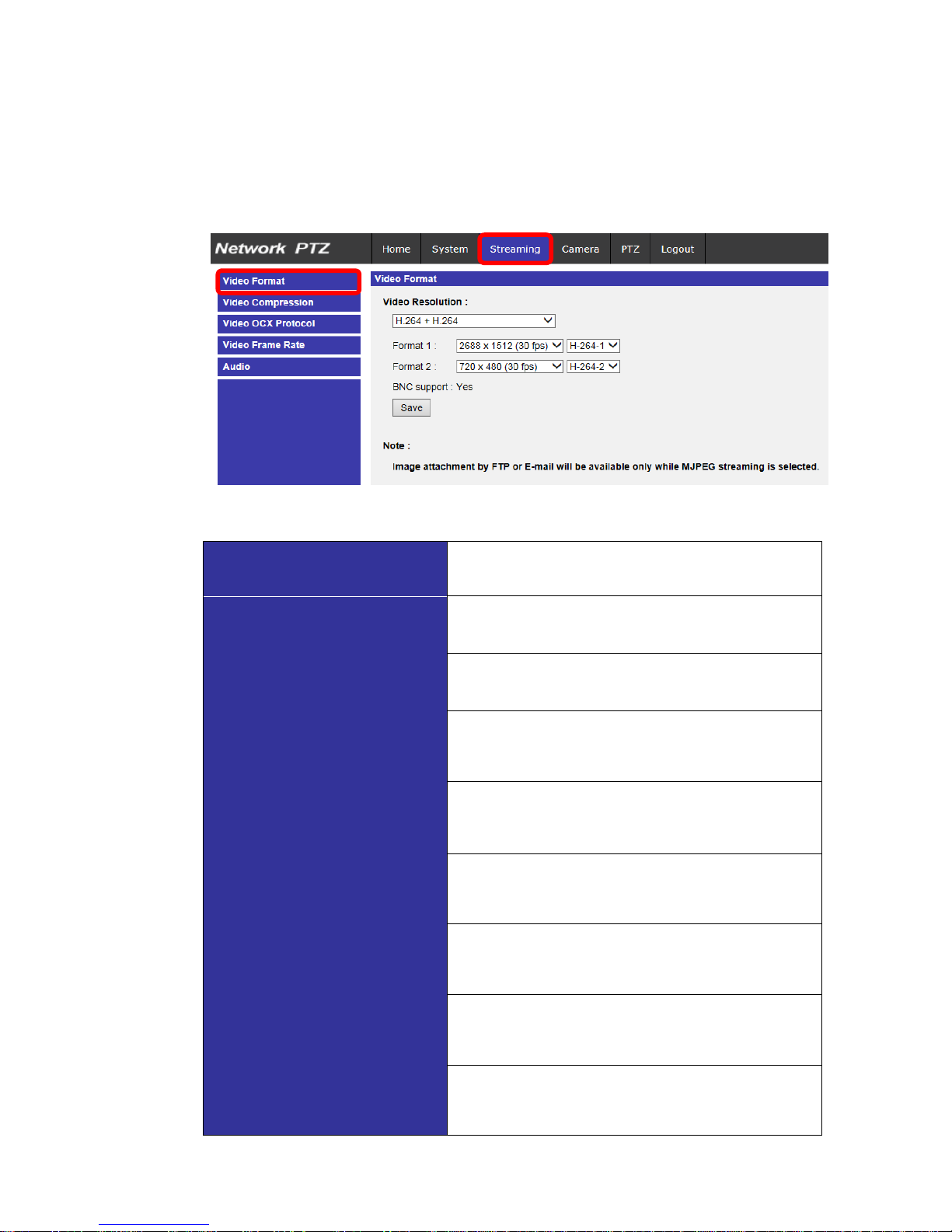
6. Setup Video Resolution
Users can setup video resolution on Video Format page of the user-friendly
browser-based configuration interface.
Video Format can be found under this path: Streaming> Video Format.
The default value of the video resolution is as below.
Normal Mode
H.264- 1920 x 1080 (60/50 fps) +
H.264- 720 x 480 (60 fps) / 720 x 576 (50 fps)
2M
HDR Mode-2
Shutter
H.264- 1920 x 1080 (30/25 fps) +
H.264- 720 x 480 (30 fps) / 720 x 576 (25 fps)
HDR Mode-3
Shutter
H.264- 1920 x 1080 (30/25 fps) +
H.264- 720 x 480 (30 fps) / 720 x 576 (25 fps)
Normal Mode
H.264- 2048 x 1536 (60/50 fps) +
H.264- 720 x 480 (60 fps) / 720 x 576 (50
fps)
3M HDR Mode-2
Shutter
H.264- 2048 x 1536 (30/25 fps) +
H.264- 720 x 480 (30 fps) / 720 x 576 (25
fps)
HDR Mode-3
Shutter
H.264- 2048 x 1536 (15/13 fps) +
H.264- 720 x 480 (15 fps) / 720 x 576 (13
fps)
Normal Mode
H.264- 2688 x 1512 (30/25 fps) +
H.264- 720 x 480 (30 fps) / 720 x 576 (25
fps)
4M
HDR Mode-2
Shutter
H.264- 2560 x 1440 (30/25 fps) +
H.264- 720 x 480 (30 fps) / 720 x 576 (25
fps)
HDR Mode-3
Shutter
H.264- 2560 x 1440 (15/13 fps) +
H.264- 720 x 480 (15 fps) / 720 x 576 (13
fps)

21
For more details about the combinations of video resolution, please refer to the Network IR PTZ
Camera Menu Tree in the supplied CD.

22
7. Configuration Files Export / Import
To export / import configuration files, users can access the Maintenance page
on the user-friendly browser-based configuration interface.
The Maintenance setting can be found under this path: System> Maintenance.
Users can export configuration files to a specified location and retrieve data by
uploading an existing configuration file to the camera. It is especially convenient
to make multiple cameras having the same configuration.
Export
Users can save the system settings by exporting the configuration file (.bin) to a
specified location for future use. Click on the <Export> button, and the popup
File Download window will come out. Click on <Save> and specify a desired
location for saving the configuration file.
Upload
To upload a configuration file to the camera, click on <Browse> to select the
configuration file, and then click on the <Upload> button for uploading.

23
8. Tech Support Information
This chapter will introduce how to delete previously-installed DCViewer in the PC and
how to setup the Internet security.
8.1
Deleting the Exisiting DCViewer
For users who have installed the DCViewer in the PC previously, please remove
the existing DCViewer from the PC before accessing to the IP camera.
Deleting the DCViewer
In the Windows <Start Menu>, activate <Control Panel>, and then double click
on <Add or Remove Programs>. In the <Currently installed programs> list,
select <DCViewer> and click on the button <Remove> to uninstall the existing
DCViewer.
Deleting Temporary Internet Files
To improve browser performance, it is suggested to clean up all the files in the
<Temporary Internet Files>. The procedure is as follows.
Step 1: In the web browser, clicks on the <Tools> tab on the menu bar and
select <Internet Options>.
Step 2: Click on the <Delete> button under the <Browsing History> section.
Step 3: In the appeared window, tick the box beside the <Temporary Internet
Files> and click on <Delete> to start deleting the files.

24
8.2
Setup Internet Security
If ActiveX control installation is blocked, please either set Internet security level
to default or change ActiveX controls and plug-ins settings.
Internet Security Level: Default
Step 1: Start the Internet Explorer (IE).
Step 2: Click on the <Tools> tab on the menu bar and select <Internet
Options>.
Step 3: Click on the <Security> tab, and select <Internet> zone.
Step 4: Down the page, click on the <Default Level> button and click on <OK>
to confirm the setting. Close the browser window, and restart a new
one later to access the IP camera.
ActiveX Controls and Plug-ins Settings
Step 1: Repeat Step 1 to Step 3 of the previous section above.
Step 2: Down the page, click on the <Custom Level> button to change ActiveX
controls and plug-ins settings. The Security Settings window will pop
up.
Step 3: Under <ActiveX controls and plug-ins>, set ALL items (as listed below)
to <Enable> or <Prompt>. Please note that the items vary by IE
version.
Step 4: Click on <OK> to accept the settings. A prompt window will appear for
confirming the setting changes, click <Yes(Y)> to close the Security
Setting window.
Step 5: Click on <OK> to close the Internet Options screen.
Step 6: Close the browser window, and restart a new one later to access the IP
camera.
ActiveX controls and plug-ins settings:
1.
Binary and script behaviors.
2.
Download signed ActiveX controls.
3.
Download unsigned ActiveX controls.
4.
Allow previously unused ActiveX controls to run without prompt.
5.
Allow Scriptlets.
6.
Automatic prompting for ActiveX controls.
7.
Initialize and script ActiveX controls not marked as safe for scripting.
8.
Run ActiveX controls and plug-ins.
9.
Only allow approved domains to use ActiveX without prompt.
10.
Script ActiveX controls marked safe for scripting*.
11.
Display video and animation on a webpage that does not use external media player.

25
9. Menu Tree
There are six setting tabs, including <Home>, <System>, <Streaming>,
<Camera>, <PTZ> and <Logout> on the Home Page.
Home
Users can monitor the live video of the targeted area.
System Setting
The administrator can set host name, system time, root password, network
related settings, etc. Further details will be interpreted in chapter System.
Streaming Setting
The administrator can configure video format, video compression, video OCX
protocol, video frame rate and audio compression in this page.
Camera Setting
This setting page is only available for the administrator and user accounts that
have been granted the privilege of camera control. The administrator and users
can adjust various camera parameters including Exposure, White Balance,
Sharpness, IR Function, Digital Zoom, WDR, etc.
PTZ Setting
This setting page is only available for the administrator and user accounts that
have been granted the privilege of camera control. The administrator and users
can program Preset Point(s), Cruise Line(s), Auto Pan Path(s) and Sequence
Line(s) via PTZ controls.
Logout
Click on the tab to re-login the camera with another username and password.
26
9.1
Home Page
Click on the tab <Home> to access the <Home> Page. There are several
function buttons on this page. Detailed information of each item is as described
in the following section.
9.1.1
Function Items on Home Page
Multiple Languages Support
Multiple languages are supported, including German, English, Spanish, French,
Italian, Japanese, Portuguese, Russian, Simplified Chinese and Traditional
Chinese for the viewer window interface.
Display Stream Selection
According to the streaming setting, users can choose the one stream to display
from the drop-down list.
Zoom Adjustment
Click on the buttons <WIDE / TELE> to control zoom in / out. Or move the
cursor to the zoom adjustment drop-down menu to adjust the zoom ratio.

27
Focus Adjustment
Near / Far Buttons
Click on the <MANUAL> button first, and users can adjust focus
manually via <NEAR> and <FAR> buttons.
Auto Focus (Continuous AF)
Click on the <AUTO> button to enable AF mode. In this mode, the
camera will keep in focus automatically and continuously regardless
of zoom changes or any view changes.
Manual Button
Click on the <MANUAL> button, and users can adjust focus manually
via
NEAR / FAR buttons.
Zoom Button (Zoom Triggered AF)
Click on the <ZOOM> button, and AF will be activated every time when
zoom is adjusted
Iris Adjustment
Click on the buttons / > to control the brightness of the
image. Or click on > to go back to the default value.
Control Panel Button
(Close / Open)
Click on the <Control Panel> button to open and close the control
panel.
After clicking the <Control Panel> Button, the control panel will be shown as the
figure below.
Pan & Tilt Direction and Speed Control
The <Pan & Tilt Direction Control> arrows on the control panel allow
users to control the camera to intended direction. And users can set a
number between 1 and 10 to determine the pan/tilt speed of the
camera from the drop-down list on the control panel. 1 is the slowest
and 10 is
the fastest.
28
Run Preset / Cruise / Sequence
After setup the Preset / Cruise / Sequence lines according to the PTZ
Settings, select a Preset / Cruise / Sequence line and start it from the
drop-down list.
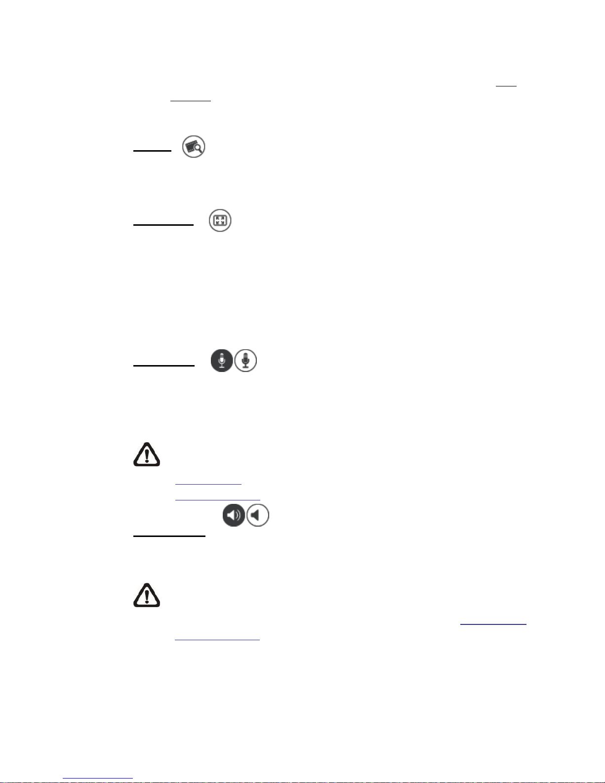
Quality
Click to show/hide the video quality information including bitrate
and compression.
Full Screen
Image display size can be adjusted to full screen. Alternatively, right click on
the Live Video Pane and select <Fullscreen> to go full screen.
To exit full screen mode, users can (1) tap <Esc> on the keyboard; (2) double
click on the Live Video Pane; (3) right click on the Live Video Pane and select
<Normal view>.
Talk Button
(On / Off)
Talk function allows the local site talks to the remote site. Click on the button
to switch it to On / Off. Users must select the suitable transmission mode
under this path: Streaming> Audio to enable this function.
NOTE: This function is only available for user accounts that have
been granted this privilege by the administrator. Please refer to
Security: Add
user> Talk/Listen for further details.
Listen Button
(On / Off)
Click on the <Listen> button to mute / activate the audio. Users must select the
suitable transmission mode under Streaming> Audio to enable this function.
NOTE: This function is only available for user accounts that have been
granted this privilege by the administrator. Please refer to Security: Add
user> Talk/Listen for further details.

29
Snapshot Button
Click on the button and the JPEG snapshots will automatically be saved in
the appointed place. The default place of saving snapshots is: C:\. To
change the storage location, please refer to section File Location of the next
chapter for further details.
NOTE: With Windows 7 operating system or above, to implement
the Snapshot function, users must run IE as administrator. To run IE
as administrator, right click on the IE browser icon and select “Run
As Administrator” to launch IE.
Live View Pause / Restart Button
(Pause / Restart)
Click on the <Pause> button to disable video streaming, the live video will be
displayed as black. Press the <restart> button to show the live video.
Record Button
(On / Off)
Click on the <Record> button and the Live View through the web browsing
will be directly recorded to the specific location on the local hard drive, which
could be configured in the <File Location> page. The default storage
location for the web recording is: C:\. Please refer to section File Location of
the next chapter for further details.
NOTE: With Windows 7 operating system or above, to implement
the Web Recording function, users must run IE as administrator. To
run IE as administrator, right click on the IE browser icon and select
“Run As
Administrator” to launch IE.
Manual Trigger Button
(On / Off)
Click on the <Manual Trigger > button to turn on and off the manual
trigger. Please refer to section Manual Trigger of the next chapter for
further details.

30
Pan/Tilt Control
Users can implement pan/tilt control by moving the cursor to the live video pane,
then left click and drag the pointer in any direction.
Optical / Digital Zoom Control
In Normal View display mode, users can implement zoom in / out by moving the
cursor to the live video pane and scrolling the mouse wheel. Digital zoom is only
available when the function is activated in <Digital Zoom> page under the
<Camera> tab. When the camera reaches the limit of its optical range, it will
automatically switch to digital zoom.
Set Center Mode
Right click on the Live Video Pane and select <Set Center Mode>. Then users
can position the interest area in the center of the Live Video Pane automatically
by clicking on the point of interest. In <Set Center Mode>, right click on the Live
Video Pane again and select <Set Emulated Joystick Mode> to return to control
the camera direction by left clicking and dragging the pointer
on the Live
Video Pane.

31
9.2
System
Under the tab <System>, the categories are shown as the configure page
below.
NOTE: The <System> configuration page is only accessible by the
administrator.
9.2.1
System
The System setting can be found under the path: System> System.
Host Name
The name is for camera identification. If the alarm function (refer to section
Events) is enabled and is set to send alarm messages by Mail / FTP, the host
name entered here will be displayed in the alarm message.
Time Zone
Select the time zone from the drop-down menu according to the location of the
camera.
Enable Daylight Saving Time
To enable DST, please check the item and then specify the time offset and the
DST duration. The format for time offset is [hh:mm:ss]; for instance, if the
amount of time offset is one hour, please enter “01:00:00” into the field.

32
Time format
Choose a time format (yyyy/mm/dd or dd/mm/yyyy) from the drop-down menu.
The format of the date and time displayed above the live video window will be
changed according to the selected format.
Sync with Computer Time
Select the item, and video date and time display will synchronize with the PC’s.
NOTE: Users MUST click on the <Save> button to confirm the setting.
Otherwise, the time will not be synced.
Manual
The administrator can set video date and time manually. Entry format should be
identical with the examples shown next to the enter fields.
Sync with NTP Server
Network Time Protocol (NTP) is an alternate way to synchronize the camera’s
clock with a NTP server. Please specify the server that is wished to synchronize
in the entry field. Then select an update interval from the drop-down menu.
For further information about NTP, please see the web site: www.ntp.org.
NOTE: The synchronization will be done every time the camera boots
up.
Click on <Save> to confirm the setting.

33
9.2.2
Security
The Security setting can be found under this path: System> Security.
Click on the <Security> category, there will be a drop-down menu with tabs
including <User>, <HTTPS>, <IP Filter>, and <IEEE 802.1X>.
9.2.2.1 User
The User setting can be found under this path: System> Security> User.
Admin Password
This item is for the administrator to reset password. Enter the new password in
<Admin password> and <Confirm password>. The maximum length is 14
characters. The input characters / numbers will be displayed as dots for security
purposes. Click on <Save> to confirm the changes. After the changes are
confirmed, the web browser will ask the administrator to re-login to the camera
with the new password.
NOTE: The following characters are valid: A-Z, a-z, 0-9, !#$%&’-.@^_~.
Add User
This item is for the administrator to add new users. Enter the new user’s name
in <User name> and the password in <User password>. Username can be up to
16 characters, and the maximum length of the password is 14 characters. Tick
the boxes below to give privileges for functions, including “Camera control”,
“Talk” and “Listen”. Click on <Add> to add the new user. The name of the new
added user will be displayed in the <User name> drop-down list under <Manage
User>. There is a maximum of twenty user accounts.
I/O access
This item supports fundamental functions that enable users to view the
live video when accessing to the camera.
Camera control
This item allows the appointed user to change camera parameters on
the <Camera> and <PTZ> setting page.

34
Talk/Listen
This item allows the appointed user in the local site (PC site) to
communicate with, for instance, the administrator in the remote site.
Manage User
Delete user
Pull down the <User name> drop-down list and select the username that
is wished to be deleted. Click on <Delete> to remove the selected name.
Edit user
Pull down the <User name> drop-down list and select the username.
Click on <Edit> and a popup window will appear. In the appeared
window, enter the new user password and reset the privileges. Click on
<Save> to confirm the changes. Then click on <Close> to complete the
editing.
HTTP Authentication Setting
This setting allows secured connections between the IP camera and web
browser by enforcing access controls to web resources. When users approach
to the web browser, it’ll ask for username and password, which protects the
camera settings or live streaming information from snooping. There are two
security models available: Basic and Digest. Refer to the descriptions below for
more details.
Basic
This mode can only provide basic protection for the connection security.
There will still be risks for the password being intercepted.
Digest
Digest mode is a safer option for protection. The password is sent in an
encrypted format to prevent it from being stolen.
NOTE: Users MUST click on the <Save> button to apply the setting.

35
Streaming Authentication Setting
This setting provides security against unauthorized users from getting streaming
via Real Time Streaming Protocol (RTSP). If the setting is enabled, users will be
requested to enter user name and password before viewing the live streams.
There are three security modes available: Disable, Basic and Digest. Refer to
the descriptions below for more details.
Disable
If disable mode is selected, there will be no security provided to against
unauthorized access. Users will not be asked to input user name and
password for authentication.
Basic
This mode can only provide basic protection for the live streams.
There will still be risks for the password being intercepted.
Digest
Digest mode is a safer option for protection. The password is sent in an
encrypted format to prevent it from being stolen.
NOTE: Users MUST click on the <Save> button to apply the setting.

36
9.2.2.2 HTTPS
The HTTPS setting can be found under this path: System> Security> HTTPS.
<HTTPS> allows secure connections between the camera and the web browser
using <Secure Socket Layer (SSL)> or <Transport Layer Security (TLS)>, which
ensure camera settings or Username / Password info from snooping. It is
required to install a self-signed certificate or a CA-signed certificate for
implementing HTTPS.
To use HTTPS on the camera, an HTTPS certificate must be installed.
The HTTPS certificate can be obtained by either creating and sending a
certificate request to a Certificate Authority (CA) or creating a self-signed
HTTPS certificate, as described below.
Create Self-signed Certificate
Before a CA-issued certificate is obtained, users can create and install a selfsigned certificate first.
Click on <Create> under “Create self-signed certificate” and provide the
requested information to install a self-signed certificate for the camera.
Please refer to the last part of this section Provide the Certificate Information for
more details.
NOTE: The self-signed certificate does not provide the same high level
of security as when using a CA-issued certificate.
Install Signed Certificate
Click on the <Create Certificate Request> button to create and submit a
certificate request in order to obtain a signed certificate from CA.
Provide the request information in the create dialog. Please refer to the
following section Provide the Certificate Information for more details.
When the request is complete, the subject of the Created Request will be shown
in the field. Click on <Properties> below the Subject field, copy the PEMformatted request and send it to the selected CA.
When the signed certificate is returned, install it by uploading the signed
certificate.

37
Provide the Certificate Information
To create a Self-signed HTTPS Certificate or a Certificate Request to CA,
please enter the information as requested.
Create Self Signed
Certificate
Create Certificate Request
Country
v
v
State or Province
v
v
Locality
v
v
Organization
v
v
Organizational Unit
v
v
Common Name
v
v
Valid Days
v -
Country
Enter a two-letter combination code to indicate the country the certificate
will be used in. For instance, type in “US” to indicate United States.
State or province
Enter the local administrative region.
Locality
Enter other geographical information.
Organization
Enter the name of the organization to which the entity identified in
“Common Name” belongs.
Organization Unit
Enter the name of the organizational unit to which the entity identified in
“Common Name” belongs.
Common Name
Indicate the name of the person or other entity that the certificate
identifies (often used to identify the website).
Valid days
Enter the period in days (1 to 9999) to indicate the valid period of
certificate.
Click on <OK> to save the Certificate Information after completing the setting.

38
9.2.2.3 IP Filter
The IP Filter setting can be found under this path: System> Security> IP Filter.
With IP Filter, users can allow or deny specific IP addresses from accessing the
camera.
Enable IP Filter
Check the box to enable the IP Filter function. Once enabled, the listed
IP addresses (IPv4) in the <Filtered IP Addresses> list box will be
allowed / denied to access the camera.
Select <Allow> or <Deny> from the drop-down list and click on the
<Apply> button to determine the IP filter behavior.
Add IP Address
Input IP address at the blank space below the <Filtered IP Address> list
and click <Add>. The newly-added address will be shown in the list. Up
to 256 IP address entries can be specified.
In addition, to filter a group of IP addresses, enter an address at the
blank space followed with a slash and a number ranging from 1 to 31,
e.g.
192.168.2.81/30. The number after the slash can define how many
IP addresses will be filtered. For details, please refer to the following
example.
Example: Filtering a group of consecutive IP addresses
The steps below show what will be filtered when 192.168.2.81/30 is
entered.
Step 1: Convert 192.168.2.81 to binary numbers. The binary
numbers are 11000000.10101000.00000010.01010001. Users can
refer to Appendix B: IP Addresses from Decimal to Binary for
converting the IP addresses to binary numbers. The number “30”
after the slash is referring to the first 30 digits of the binary numbers.
Step 2: Convert a few IP addresses before and after 192.168.2.81
to binary numbers. Then compare their first 30 digits with the binary
numbers of 192.168.2.81.

39
a.
Convert 192.168.2.80 to binary numbers. The binary numbers
are 11000000.10101000.00000010.01010000. The first 30
digits are the same with the binary numbers of 192.168.2.81,
thus 192.168.2.80 will be filtered.
b.
Convert 192.168.2.79 to binary numbers. The binary numbers
are 11000000.10101000.00000010.01001111. The first 30
digits are different with the binary numbers of 192.168.2.81,
thus 192.168.2.79 will not be filtered. This also means the IP
addresses before 192.168.2.79 will not be filtered. Therefore,
users can stop converting the IP addresses before
192.168.2.79 to binary numbers.
c.
Repeat the same procedure in “a” with the IP addresses after
192.168.2.81. Stop when the situation occurs in “b” happened.
Namely, the 30th digit of the binary numbers of IP address
192.168.2.84 is different, and will not be filtered.
As a result, the IP addresses 192.168.2.80 to 192.168.2.83 will be
filtered when entering 192.168.2.81/30. The following table clearly
shows the 30th digit of the binary numbers of IP addresses
192.168.79 and 192.168.84 are different from the others. Therefore,
these two IP addresses will not be filtered.
IP Addresses
Binary Numbers
192.168.2.79
11000000.10101000.00000010.01001111
192.168.2.80
11000000.10101000.00000010.01010000
192.168.2.81
11000000.10101000.00000010.01010001
192.168.2.82
11000000.10101000.00000010.01010010
192.168.2.83
11000000.10101000.00000010.01010011
192.168.2.84
11000000.10101000.00000010.01010100
Delete IP Address
To remove an IP address from the <Filtered IP Address> list, please
select the address and click on <Delete>.

40
9.2.2.4 IEEE 802.1X
The IEEE 802.1X setting can be found under this path: System> Security>
IEEE 802.1X.
The camera is allowed to access a network protected by 802.1X/EAPOL
(Extensible Authentication Protocol over LAN).
Users need to contact with the network administrator for gaining certificates,
user IDs and passwords.
CA Certificate
The CA certificate is created by the Certification Authority for the purpose of
validating itself. Upload the certificate for checking the server’s identity.
Client Certificate / Private Key
Upload the Client Certificate and Private Key for authenticating the camera
itself.
Settings
Identity
Enter the user identity associated with the certificate. Up to 16
characters can be used.
Private Key Password
Enter the password (maximum 16 characters) for user identity.
Enable IEEE 802.1X
Check the box to enable IEEE 802.1X.
Click on <Save> to save the IEEE 802.1X/EAP- TLS setting.

41
9.2.3
Network
The Network setting can be found under this path: System> Network.
Click on the <Network> category, there will be a drop-down menu with tabs
including <Basic>, <QoS>, <SNMP>, and <UPnP>.
9.2.3.1 Basic
The Basic setting can be found under this path: System> Network> Basic.
This setting page is for setting a new IP address for the camera, configuring
other network-related parameters and activating IPv6 address (if the network
supports it).
General
This setting menu is for configuring a new IP address for the camera. To setup
an IP address, please find out the network type first. Contact the network
provider for it. Then refer to the network type and follow the instructions to setup
the IP address.
NOTE: If the network type is Point-to-Point Protocol over Ethernet
(PPPoE), please obtain the PPPoE username and password from the
network provider.
Get IP address automatically (DHCP)
Select the item and click <Save> to confirm the new setting. A note for
camera system restart will appear. Click <OK> and the camera system
will be restarted. The camera will be assigned with a new IP address.
Close the web browser and search the camera through the installer
program: DeviceSearch.exe, which can be found in “DeviceSearch”
folder in the supplied CD. Refer to the steps below to connect the
camera through “DeviceSearch” software.
NOTE: Before searching the camera through DeviceSearch.exe,
please record the camera’s MAC address, which can be found
on the label or on the package container of the camera, for later
use and identification in the future.

42
Step 1: Double click on the program DeviceSearch.exe.
Step 2: After its window appears, click on the <Device Search> button
on the top. All the finding IP devices will be listed in the page.
Step 3: Find the camera by its MAC address.
Step 4: Then double click or right click and select <Browse> to access
the camera directly by the web browser.
Step 5: A prompt window requesting for the username and the
password will appear. Enter the username and the password to
login to the camera.
Use fixed IP address
Select the item and insert the new IP address, e.g. 192.168.7.123. Note
that the inserted IP address should be in the same LAN as the PC’s IP
address. Then go to the Default gateway (explained later) blank and
change the setting, eg. 192.168.7.254. Click on <Save> to confirm the
new setting. A note for system restart will appear, click <OK> and the
system will restart. Wait for 15 seconds. The camera’s IP address in the
URL bar will be changed, and users have to login again.
When using a static IP address to connect the camera, users can
access the camera by inputting the IP address in the URL bar and hit
<Enter> on the keyboard. Alternatively, users can access the camera by
the installer program: DeviceSearch.exe, which can be found in
“DeviceSearch” folder in the supplied CD. Refer to the steps below to
connect the camera through “DeviceSearch” software with a static IP
address.
Step 1: Double click on the program DeviceSearch.exe.
Step 2: After its window appears, click on the <Device Search> button
on the top. All the finding IP devices will be listed in the page.
Step 3: Find the camera by its IP address.
Step 4: Then double click or right click and select <Browse> to access
the camera directly by the web browser.

43
Step 5: A prompt window requesting for the username and the
password will appear. Enter the username and the password to
login to the camera.
IP address
This is necessary for network identification.
Subnet mask
It is used to determine if the destination is in the same subnet. The
default value is “255.255.255.0”.
Default gateway
This is the gateway used to forward frames to destinations in
different subnet. Invalid gateway setting will fail the transmission to
destinations in different subnet.
Primary DNS
Primary DNS is the primary domain name server that translates
hostnames into IP addresses.
Secondary DNS
Secondary DNS is a secondary domain name server that backs up
the primary DNS.
Use PPPoE
For the PPPoE users, enter the PPPoE username and password into
the enter fields, and click on the <Save> button to complete the setting.

44
Advanced
The following introduces the camera’s Web Server port, RTSP port, MJPEG
over HTTP port, and HTTPS port.
Web Server port
The default web server port is 80. With the default web server port ‘80’,
users can simply input the IP address of the camera in the URL bar of a
web browser to connect the camera. When the web server port is
changed to any number other than 80, users have to enter the camera’s
IP address followed by a colon and the port number. For instance, a
camera whose IP address as 192.168.0.100 and web server port as
8080 can be connected by entering “http://192.168.0.100:8080” in the
URL bar.
RTSP port
The default setting of RTSP Port is 554; the RTSP Port should be set as
554 or from the range 1024 to 65535.
MJPEG over HTTP port
The default setting of MJPEG over HTTP Port is 8008; the MJPEG over
HTTP Port should be set as 8008 or from the range1024 to 65535.
HTTPS port
The default setting of HTTPS Port is 443; the HTTPS Port should be set
as 443 or from the range 1024 to 65535.
NOTE: Please make sure the port numbers set above are not the same
with each other; otherwise, network conflict may occur.
IPv6 Address Configuration
If the network supports IPv6, users can check the box beside <Enable IPv6>
and click <Save>. An IPv6 address will appear beside <Address>, and users
can use it to connect to the camera.

45
9.2.3.2 QoS
The QoS (Quality of Service) setting can be found under this path: System>
Network> QoS.
QoS allows providing differentiated service levels for different types of traffic
packets, which guarantees delivery of priority services especially when network
congestion occurs. Adapting the Differentiated Services (DiffServ) model, traffic
flows are classified and marked with DSCP (DiffServ Codepoint) values, and
thus receive the corresponding forwarding treatment from DiffServ capable
routers.
DSCP Settings
The DSCP value range is from 0 to 63. The default DSCP value is 0, which
means DSCP is disabled. The camera uses the following QoS Classes: Video,
Audio and Management.
Video DSCP
The class consists of applications such as MJPEG over HTTP,
RTP/RTSP and RTSP/HTTP.
Audio DSCP
This setting is only available for the cameras that support audio.
Management DSCP
The class consists of HTTP traffic: Web browsing.
NOTE: To enable this function, please make sure the switches / routers
in the network support QoS.

46
9.2.3.3 SNMP
The SNMP (Simple Network Management Protocol) setting can be found under
this path: System> Network> SNMP.
With Simple Network Management Protocol (SNMP) support, the camera can
be monitored and managed remotely by the network management system.
SNMP v1 / v2
Enable SNMP v1 / v2
Select the version of SNMP to use by checking the box.
Read Community
Specify the community name that has read-only access to all supported
SNMP objects. The default value is “public”.
Write Community
Specify the community name that has read / write access to all
supported SNMP objects (except read-only objects). The default value is
“private”.
SNMP v3
SNMP v3 supports an enhanced security system that provides protection
against unauthorized users and ensures the privacy of the messages. Users will
be requested to enter security name, authentication password and encryption
password while setting the camera connections in the network management
system. With SNMP v3, the messages sent between the cameras and the
network management system will be encrypted to ensure privacy.
Enable SNMP v3
Enable SNMP v3 by checking the box.
Security Name
The maximum length of the security name is 32 characters.
NOTE: The valid characters are A-Z, a-z, 0-9 and !#$%&’-.@^_~.
Authentication Type
There are two authentication types available: MD5 and SHA. Select
<SHA> for a higher security level.

47
Authentication Password
The authentication password must be 8 characters or more. The input
characters / numbers will be displayed as dots for security purposes.
NOTE: The valid characters are A-Z, a-z, 0-9 and !#$%&’-.@^_~.
Encryption Type
There are two encryption types available: DES and AES. Select <AES>
for a higher security level.
Encryption Password
The minimum length of the encryption password is 8 characters and the
maximum length is 512 characters. The input characters / numbers will
be displayed as dots for security purposes. The encryption password
can also be left blank. However, the messages will not be encrypted to
protect privacy.
NOTE: The valid characters are A-Z, a-z, 0-9 and !#$%&’-.@^_~.
Traps for SNMP v1 / v2 / v3
Traps are used by the camera to send massages to a management system for
important events or status changes.
Enable Traps
Check the box to activate trap reporting.
Trap address
Enter the IP address of the management server.
Trap community
Enter the community to use when sending a trap message to the
management system.
Trap Option
Warm Start
A Warm Start SNMP trap signifies that the SNMP device, i.e. IP camera,
performs software reload.
Click on <Save> button when complete.

48
9.2.3.4 UPnP
The UPnP setting can be found under this path: System> Network> UPnP.
UPnP Setting
Enable UPnP
When the UPnP is enabled, whenever the camera is presented to the
LAN, the icon of the connected cameras will appear in My Network
Places to allow for direct access.
NOTE: To enable this function, please make sure the UPnP
component is installed on the computer. Please refer to
Appendix A: Install UPnP Components for UPnP component
installation procedure.
Enable UPnP port forwarding
When the UPnP port forwarding is enabled, the camera is allowed to
open the web server port on the router automatically.
NOTE: To enable this function, please make sure that the router
supports UPnP and it is activated.
Friendly name
Set a name for the camera for identity.
Click on <Save> when finished.

49
9.2.4
DDNS
The DDNS setting can be found under this path: System> DDNS.
Dynamic Domain Name System (DDNS) allows a host name to be constantly
synchronized with a dynamic IP address. In other words, it allows those using a
dynamic IP address to be associated to a static domain name so others can
connect to it by name.
Enable DDNS
Check the item to enable DDNS.
Provider
Select one DDNS host from the provider list.
Host name
Enter the registered domain name in the field.
Username/E-Mail
Enter the username or E-mail required by the DDNS provider for authentication.
Password/Key
Enter the password or key required by the DDNS provider for authentication.
9.2.5
Mail
The Mail setting can be found under this path: System> Mail.
The administrator can send an E-mail via Simple Mail Transfer Protocol (SMTP)
when an alarm is triggered. SMTP is a protocol for sending E-mail messages
between servers. SMTP is a relatively simple, text-based protocol, where one or
more recipients of a message are specified and the message text is transferred.
Two sets of SMTP can be configured. Each set includes SMTP Server, Account
Name, Password and E-mail Address settings. For SMTP server, contact the
network service provider for more specific information.

50
9.2.6
FTP
The FTP setting can be found under this path: System> FTP.
The administrator can set the camera to send the alarm messages to a specific
File Transfer Protocol (FTP) site when an alarm is triggered. Users can assign
alarm message to up to two FTP sites. Enter the FTP details, which include
server, server port, username, password and remote folder, in the fields.
Click on <Save> when finished.
9.2.7
HTTP
The HTTP setting can be found under this path: System> HTTP.
An HTTP Notification server can listen for the notification messages from the
cameras by triggered events. Enter the HTTP details, which include server
name (for instance, http://192.168.0.1/admin.php), username, and password in
the fields. <Alarm> triggered and <Motion Detection> notifications can be sent
to the specified HTTP server.
Click on <Save> when finished.
Please refer to Events> Application> Send HTTP notification for HTTP
Notification settings.

51
9.2.8
Events (Alarm Settings)
The Events setting can be found under this path: System> Events.
Click on the <Events> category, there will be a drop-down menu with tabs
including <Application>, <Motion Detection>, <Network Failure Detection>,
<Periodical Event>, <Manual Trigger>, and <Audio Detection>.
9.2.8.1 Application
The Application setting can be found under this path: System> Events>
Application.
The camera equips four alarm inputs and two relay outputs for cooperating with
the alarm system to catch events’ images. Please refer to the User’s Manual in
the supplied CD for alarm I/O pin definitions to connect the alarm devices.
Alarm Setting
Alarm Switch
Select an alarm pin which is to be configured from the drop-down menu.
The default setting for the Alarm Switch function is <Off>. Enable the
function by selecting <On>. Users can also activate the function
according to the schedule previously set in the <Schedule> setting page.
Select <By schedule> and click <Please select…> to choose the desired
schedule from the drop-down menu.
Alarm Type
Select an alarm type, <Normal close> or <Normal open>, that
corresponds with the alarm application.

52
Triggered Action (Multi-option)
The administrator can specify alarm actions that will take at an alarm
occurrence. All options are listed as follows.
Enable Alarm Output 1/2
Select these items to enable alarm relay outputs.
Send Message by FTP/E-Mail
The administrator can select whether to send an alarm message by FTP
and/or E-mail when an alarm is triggered.
Upload Image by FTP
Select this item and the administrator can assign an FTP site and
configure various parameters. When the alarm is triggered, event
images will be uploaded to the appointed FTP site.
<Pre-trigger buffer> function allows users to check what caused the
trigger. The <Pre-trigger buffer> frame rate could be pre-determined.
On the other hand, <Post-trigger buffer> is for users to upload certain
amount of images after the alarm input is triggered.
NOTE: Normally the setting range of the <Pre-trigger buffer> is 1
frame to 20 frames. However, the setting range will change
accordingly if the frame rate of MJPEG on the <Video Frame
Rate> setting page is 6 or smaller.
Check the box <Continue image upload> to upload the triggered images
during certain time or keep uploading until the trigger is off.
Select <Upload for sec> and enter the duration in the blank.
The images of the duration will be uploaded to FTP when the alarm input
is triggered. The setting range is from 1 sec. to 99999 sec. Select
<Upload while the trigger is active> to make the images keep being
uploaded to FTP during the trigger active until the alarm is released. Set
the Image frequency as the upload frame rate. The setting range is from
1 frame to 15 frames per second.
NOTE: Make sure the FTP configuration has been completed.
Refer to section FTP for further details.

53
Upload Image by E-Mail
Select this item and the administrator can assign an E-mail address and
configure various parameters. When the alarm is triggered, event
images will be sent to the appointed E-mail address.
<Pre-trigger buffer> function allows users to check what happened to
cause the trigger. The <Pre-trigger buffer> frame rate could be predetermined. On the other hand, <Post-trigger buffer> is for users to
upload certain amount of images after alarm input is triggered.
NOTE: Normally the setting range of the <Pre-trigger buffer> is 1
frame to 20 frames. However, the setting range will change
accordingly if the frame rate of MJPEG on the <Video Frame
Rate> setting page is 6 or smaller.
Check the box <Continue image upload> to upload the triggered images
during certain time or keep uploading until the trigger is off.
Select <Upload for sec> and enter the duration in the blank.
The images of the duration will be uploading by E-mail when the alarm
input is triggered. The setting range is from 1 sec. to 99999 sec. Select
<Upload while the trigger is active> to make the images keep being
uploaded to E-mail during the trigger active until the alarm is released.
Set the Image frequency as the upload frame rate. The setting range is
from 1 frame to 15 frames per second.
NOTE: Make sure SMTP configuration has been completed.
Please refer to section Mail for further details.
Send HTTP Notification
Check this item, select the destination HTTP address, and specify the
parameters for event notifications by <Alarm> triggered. When an alarm
is triggered, the notification can be sent to the specified HTTP server.
For instance, if the custom parameter is set as “action=1&group=2”, and
the HTTP server name is “http://192.168.0.1/admin.php”, the notification
will be sent to HTTP server as “http://192.168.0.1/admin.php?
action=1&group=2” when alarm is triggered.

54
Record Video Clip
Check this item and select a video recording storage type, <SD Card> or
<NAS> (Network-Attached Storage). The alarm-triggered recording will
be saved into the SD card or the NAS.
Pre-trigger buffer recording function allows users to check what
happened to cause the trigger. The pre-trigger buffer time range is from
1 sec. to 3 sec. Select <Upload for sec> to set the recording duration
after alarm is triggered. The setting range is from 1 sec. to 99999 sec.
Select <Upload while the trigger is active> to record the triggered video
until the trigger is off.
NOTE: Please make sure the local recording (with SD card) or
the remote recording (with NAS) is activated so that this function
can be implemented. Refer to section Recording for further
details.
PTZ Function
Assign a camera function: Preset, Sequence, Autopan or Cruise, and
specify a Function Line for the camera to perform when an alarm is
triggered.
NOTE: Please refer to the sections Preset, Cruise, Autopan, and
Sequence for details of Preset Point / Cruise Line / Autopan Path
/ Sequence Line setups.
If the selected function is <Preset>, it is required to enter its dwell time (1
sec. to 256 sec.) in the corresponding field. When the alarm is triggered,
the camera will go to the selected Preset Point and stay there for a
user-defined period of time. As for other function modes, the camera will
keep executing the specified function; to stop the performance, simply
change the camera’s status.
NOTE: The dwell time is only adjustable when <Preset> is
selected. When the dwell time is up, the camera will go back to
its trigger position and recheck the alarm pin status.

55
File Name
Enter a file name in the File name field, e.g. image.jpg. The uploaded image’s
file name format can be set in this section. Please select the one that meets the
requirements.
Add date/time suffix
File name: imageYYMMDD_HHNNSS_XX.jpg
Y: Year, M: Month, D: Day
H: Hour, N: Minute, S: Second
X: Sequence Number
Add sequence number suffix (no maximum value)
File name: imageXXXXXXX.jpg
X: Sequence Number
Add sequence number suffix up to # and then start over
File Name: imageXX.jpg
X: Sequence Number
The file name suffix will end at the number being set. For example, if the
setting is up to “10”, the file name will start from 00, end at 10, and then
start all over again.
Overwrite
The original image in the FTP site will be overwritten by the new
uploaded file with a static filename.
Save
Click on <Save> to save the settings.

56
9.2.8.2 Motion Detection
The Motion Detection setting can be found under this path: System> Events>
Motion Detection.
Motion Detection function allows the camera to detect suspicious motion and
trigger alarms when motion volume in the detected area reaches / exceeds the
determined sensitivity threshold value.
The function supports up to 4 sets of Motion Detection Settings. Settings can be
chosen from the drop-down menu beside <Motion Detection>. In each set of
setting, there is a Motion Detection Window (the red frame shown in the figure
below) displayed on the Live Video Pane. The Motion Detection Window is for
defining the motion detection area. To change the size of the Motion Detection
Window, move the mouse cursor to the edge of the frame and draw it outward /
inward. To shift the window to the intended location, move the mouse cursor to
the center of the window and click and drag.
Users can configure up to 10 sets of Motion Detection Windows in each set of
Motion Detection Setting. Click on the <add> button under the Live Video Pane
to add a Motion Detection Window. To cancel a Motion Detection Window, move
the mouse cursor to the selected Window, and click on the <delete> button.
If Motion Detection function is activated, the pop-up window (Motion) with
indication of motion will be shown.

57
When motion is detected, the signals will be displayed on the Motion window as
shown below. Motion is detected by comparing sampling pixels in the detection
area of two consecutive live images.
Motion Detection
In each set of Motion Detection Setting, the default setting for the Motion
Detection function is <Off>. Enable the function by selecting <On>. Users can
also activate the function according to the schedule previously set in the
<Schedule> setting page. Select <By schedule> and click <Please select…> to
choose the desired schedule from the drop-down menu.
Motion Detection Setting
Users could adjust various parameters of Motion Detection in this section.
Sampling pixel interval [1-10]:
This item is used to examine the differences between two frames. Users
can configure the interval of sampling pixel. The default value is 1. For
instance, if users set the interval as 3, IP camera system will take one
sampling pixel from every 3 pixels of each row and each column in
detection area (refer to the figure below). The alarm will be triggered
when differences are detected.

58
Detection level [1-100]:
Users can configure detection level for each sampling pixel. Detection
level is how much the camera can accept the differences between two
sampling pixels. The smaller the value is, the more minor motions it
detects. The default level is 10.
Sensitivity level [1-100]:
The default level is 80, which means if 20% or more sampling pixels are
detected differently, system will detect motion. The bigger the value,
the more sensitive it is. Meanwhile, when the value is bigger, the red
horizontal line in the motion indication window will be lower accordingly.
Time interval (sec) [0-7200]:
The value is the interval between each detected motion. The default
interval is 10.
Triggered Action (Multi-option)
The administrator can specify alarm actions that will take when motion is
detected. All options are listed as follows.
Enable Alarm Output 1/2
Check the item and select the predefined type of alarm output to enable
alarm relay output when motion is detected.
Send Alarm Message by FTP/E-Mail
The administrator can select whether to send an alarm message by FTP
and/or E-mail when motion is detected.
Upload Image by FTP
Select this item and the administrator can assign an FTP site and
configure various parameters. When motion is detected, event images
will be uploaded to the appointed FTP site.
<Pre-trigger buffer> function allows users to check what happened to
cause the trigger. The <Pre-trigger buffer> frame rate could be predetermined. On the other hand, <Post-trigger buffer> is for users to
upload certain amount of images after motion event occurs.

59
NOTE: Normally the setting range of the <Pre-trigger buffer> is 1
frame to 20 frames. However, the setting range will change
accordingly if the frame rate of MJPEG on the <Video Frame
Rate> setting page is 6 or smaller.
Check the box <Continue image upload> to upload the triggered images
during certain time or keep uploading until the trigger is off.
Select <Upload for sec> and enter the duration in the blank.
The images of the duration will be uploaded to FTP when the motion
event occurs. The setting range is from 1 sec. to 99999 sec.
Select <Upload during the trigger active> to make the images keep
being uploaded to FTP during the trigger active until the event stops. Set
the Image frequency as the upload frame rate. The setting range is from
1 frame to 15 frames per second.
NOTE: Make sure FTP configuration has been completed. Refer
to section FTP for further details.
Upload Image by E-Mail
Select this item and the administrator can assign an E-mail address and
configure various parameters. When motion is detected, event images
will be sent to the appointed E-mail address.
<Pre-trigger buffer> function allows users to check what happened to
cause the trigger. The <Pre-trigger buffer> frame rate could be predetermined. On the other hand, <Post-trigger buffer> is for users to
upload certain amount of images after the motion event occurs.
NOTE: Normally the setting range of the <Pre-trigger buffer> is 1
frame to 20 frames. However, the setting range will change
accordingly if the frame rate of MJPEG on the <Video Frame
Rate> setting page is 6 or smaller.
Check the box <Continue image upload> to upload the triggered images
during certain time or keep uploading until the trigger is off.
Select <Upload for sec> and enter the duration in the blank.
The images of the duration will be uploading by E-mail when the motion
event occurs. The setting range is from 1 sec. to 99999 sec.
Select <Upload during the trigger active> to make the images keep
being uploaded to E-mail during the trigger active until the event stops.

60
Set the Image frequency as the upload frame rate. The setting range is
from 1 frame to 15 frames per second.
NOTE: Make sure SMTP configuration has been completed.
Refer to section Mail for further details.
Send HTTP Notification
Check this item, select the destination HTTP address, and specify the
parameters for event notifications by <Motion Detection> triggered.
When an alarm is triggered, the notification can be sent to the specified
HTTP server.
For instance, if the custom parameter is set as “action=1&group=2”, and
the HTTP server name is “http://192.168.0.1/admin.php”, the notification
will be sent to HTTP server as “http://192.168.0.1/admin.php?
action=1&group=2” when alarm is triggered.
Record Video Clip
Check this item and select a video recording storage type, <SD Card> or
<NAS> (Network-Attached Storage>. The Motion Detection recording
will be stored in SD card or the NAS when motion is detected.
Pre-trigger buffer recording function allows users to check what
happened to cause the trigger. The pre-trigger buffer time range is from
1 sec. to 3 sec. Select <Upload for sec> to set the recording duration
after motion is triggered. The setting range is from 1 sec. to 99999 sec.
Select <Upload during the trigger active> to record the triggered video
until the trigger is off.
NOTE: Please make sure the local recording (with SD card) or
the remote recording (with NAS) is activated so that this function
can be implemented. Refer to section Recording for further
details.

61
File Name
Enter a file name in the blank, e.g. image.jpg. The uploaded image’s file name
format can be set in this section. Please select the one that meets the
requirements.
Add date/time suffix
File name: imageYYMMDD_HHNNSS_XX.jpg
Y: Year, M: Month, D: Day
H: Hour, N: Minute, S: Second
X: Sequence Number
Add sequence number suffix (no maximum value)
File name: imageXXXXXXX.jpg
X: Sequence Number
Add sequence number suffix up to # and then start over
File Name: imageXX.jpg
X: Sequence Number
The file name suffix will end at the number being set. For example, if the
setting is up to “10”, the file name will start from 00, end at 10, and then
start all over again.
Overwrite
The original image in the FTP site will be overwritten by the new
uploaded file with a static filename.
Save
Click on <Save> to save the settings.

62
9.2.8.3 Network Failure Detection
The Network Failure Detection setting can be found under this path: System>
Events> Network Failure Detection.
Network Failure Detection allows the camera to ping another IP device (e.g.
NVR, VSS, Video Server, etc.) within the network periodically and generates
some actions in case of network failure occurs, for instance, a Video Server is
somehow disconnected.
Being capable of implementing local recording (through SD card) or remote
recording (via NAS) when network failure happens, the camera can be a backup
recording device for the surveillance system.
Detection Switch
The default setting for the Detection Switch function is <Off>. Enable the
function by selecting <On>. Users can also activate the function according to
the schedule time that is previously set in the <Schedule> setting page.
Select <By schedule> and click <Please select…> to choose the desired
schedule from the drop-down menu.
Detection Type
Input the IP device address and the period of ping time to ping. The camera will
ping the IP device every N minute(s). If it fails up to three times, the alarm will
be triggered automatically. The ping time setting range is from 1 to 99 minutes.
Triggered Action (Multi-option)
The administrator can specify alarm actions that will take when network failure
is detected. All options are listed as follows.
Enable Alarm Output 1 /2
Select the item to enable alarm relay output.
Send Alarm Message by FTP/E-Mail
The administrator can select whether to send an alarm message by FTP
and/or E-mail when an alarm is triggered.
Record Video Clip
Check the item and select a video recording storage type, <SD Card> or
<NAS> (Network-Attached Storage). The alarm-triggered recording will
be saved into the SD card.

63
Pre-trigger buffer recording function allows users to check what
happened to cause the trigger. The pre-trigger buffer time range is from
1 sec. to 3 sec. Select <Upload for sec> to set the recording duration
after alarm is triggered. The setting range is from 1 sec. to 99999 sec.
Select <Upload during the trigger active> to record the triggered video
until the trigger is off.
NOTE: Please make sure the local recording (with SD card) or
the remote recording (with NAS) is activated so that this function
can be implemented. Refer to section Recording for further
details.
Save
Click on the <Save> button to save all the settings mentioned above.

64
9.2.8.4 Periodical Event
The Periodical Event setting can be found under this path: System> Events>
Periodical Event.
With Periodical Event setting, users can set the camera to upload images
periodically to an FTP site or an E-mail address. For example, if the time interval
is set to 60 seconds, the camera will upload images to the FTP site or the E-mail
address every 60 seconds. The images to be uploaded are the images before
and after the triggered moment. Users can define how many images to be
uploaded in the <Triggered Action> section of this setting page.
Periodical Event
The default setting for the Periodical Event function is <Off>. Enable the
function by selecting <On>.
Time Interval
The default value of the time interval is 60 seconds. The setting range of the
time interval is from 60 to 3600 seconds.
Triggered Action
Upload Image by FTP
Select this item and the administrator can assign an FTP site and
configure various parameters. Images will be uploaded to the appointed
FTP site periodically.
The <Pre-trigger buffer> function can define how many images to be
uploaded before the triggered moment. The <Post-trigger buffer>
function can define how many images to be uploaded after the triggered
moment.
NOTE: Normally the setting range of the <Pre-trigger buffer> is 1
frame to 20 frames. However, the setting range will change
accordingly if the frame rate of MJPEG on the <Video Frame
Rate> setting page is 6 or smaller.
NOTE: Make sure FTP configuration has been completed.
Refer to section FTP of this chapter for further details.

65
Upload Image by E-Mail
Select this item and the administrator can assign an E-mail address and
configure various parameters. Images will be uploaded to the appointed
E-mail address periodically.
The <Pre-trigger buffer> function can define how many images to be
uploaded before the triggered moment. The <Post-trigger buffer>
function can define how many images to be uploaded after the triggered
moment.
NOTE: Normally the setting range of the <Pre-trigger buffer> is 1
frame to 20 frames. However, the setting range will change
accordingly if the frame rate of MJPEG on the <Video Frame
Rate> setting page is 6 or smaller.
NOTE: Make sure SMTP configuration has been completed.
Refer to section Mail of this chapter for further details.
File Name
Enter a file name in the blank, e.g. image.jpg. The uploaded image’s file name
format can be set in this section. Please select the one that meets the
requirements.
Add date/time suffix
File name: imageYYMMDD_HHNNSS_XX.jpg
Y: Year, M: Month, D: Day
H: Hour, N: Minute, S: Second
X: Sequence Number
Add sequence number suffix (no maximum value)
File name: imageXXXXXXX.jpg
X: Sequence Number
Add sequence number suffix up to # and then start over
File Name: imageXX.jpg
X: Sequence Number
The file name suffix will end at the number being set. For example, if the
setting is up to “10”, the file name will start from 00, end at 10, and then
start all over again.

66
Overwrite
The original image in the FTP site will be overwritten by the new
uploaded file with a static filename.
Save
Click on <Save> to save all the settings mentioned above.

67
9.2.8.5 Manual Trigger
The Manual Trigger setting can be found under this path: System> Events>
Manual Trigger.
With Manual Trigger setting, the current image(s) or video can be uploaded to
the appointed destination, such as an FTP site or an E-mail address. The
administrator can specify the triggered actions that will take when the users
switch the Manual Trigger button to ON. All options are listed as follows.
Manual Trigger
The default setting for the Manual Trigger function is <Off>. Enable the function
by selecting <On>. After the Manual Trigger function is enabled, click the
Manual Trigger button on the Home page to start uploading data. Click again to
stop uploading.
Triggered Action (Multi-option)
The administrator can specify alarm actions that will take at an alarm
occurrence. All options are listed as follows.
Enable Alarm Output 1/2
Select these items to enable alarm relay outputs.
Send Message by FTP/E-Mail
The administrator can select whether to send an alarm message by FTP
and/or E-mail when an alarm is triggered.
Upload Image by FTP
Select this item and the administrator can assign an FTP site and
configure various parameters. When the alarm is triggered, event
images will be uploaded to the appointed FTP site.
<Pre-trigger buffer> function allows users to check what happened to
cause the trigger. The <Pre-trigger buffer> frame rate could be predetermined. On the other hand, <Post-trigger buffer> is for users to
upload certain amount of images after the alarm input is triggered.
NOTE: Normally the setting range of the <Pre-trigger buffer> is 1
frame to 20 frames. However, the setting range will change
accordingly if the frame rate of MJPEG on the <Video Frame
Rate> setting page is 6 or smaller.

68
Check the box <Continue image upload> to upload the triggered images
during certain time or keep uploading until the trigger is off.
Select <Upload for sec> and enter the duration in the blank.
The images of the duration will be uploaded to FTP when the alarm input
is triggered. The setting range is from 1 sec. to 99999 sec. Select
<Upload during the trigger active> to make the images keep being
uploaded to FTP during the trigger active until the alarm is released. Set
the Image frequency as the upload frame rate. The setting range is from
1 frame to 15 frames per second.
NOTE: Make sure the FTP configuration has been completed.
Refer to section FTP for further details.
Upload Image by E-Mail
Select this item and the administrator can assign an E-mail address and
configure various parameters. When the alarm is triggered,
event images will be sent to the appointed E-mail address.
<Pre-trigger buffer> function allows users to check what happened to
cause the trigger. The <Pre-trigger buffer> frame rate could be predetermined. On the other hand, <Post-trigger buffer> is for users to
upload certain amount of images after alarm input is triggered.
NOTE: Normally the setting range of the <Pre-trigger buffer> is 1
frame to 20 frames. However, the setting range will change
accordingly if the frame rate of MJPEG on the <Video Frame
Rate> setting page is 6 or smaller.
Check the box <Continue image upload> to upload the triggered images
during certain time or keep uploading until the trigger is off.
Select <Upload for sec> and enter the duration in the blank.
The images of the duration will be uploading by E-mail when the alarm
input is triggered. The setting range is from 1 sec. to 99999 sec. Select
<Upload during the trigger active> to make the images keep being
uploaded to E-mail during the trigger active until the alarm is released.
Set the Image frequency as the upload frame rate. The setting range is
from 1 frame to 15 frames per second.
NOTE: Make sure SMTP configuration has been completed.
Please refer to section Mail for further details.

69
PTZ Function
Assign a camera function: Preset, Sequence, Autopan or Cruise, and
specify a Preset Point / Sequence Line / Autopan Path / Cruise Line for
the camera to perform at an alarm occurrence.
NOTE: Please refer to the sections through Preset Programming
to Sequence Line Programming for details of Preset Point /
Cruise Line / Autopan Path / Sequence Line setups.
If the selected function is <Preset>, it is required to enter its dwell time (1
sec. to 256 sec.) in the corresponding field. When the alarm is triggered,
the camera will go to the selected Preset Point and stay there for a
user-defined period of time. As for other function modes, the camera will
keep executing the specified function; to stop the performance, simply
change the camera’s status.
NOTE: The dwell time is only adjustable when <Preset> is
selected. When the dwell time is up, the camera will go back to
its trigger position and recheck the alarm pin status.
Send HTTP notification
Check this item, select the destination HTTP address, and specify the
parameters for event notifications by <Alarm> triggered. When an alarm
is triggered, the notification can be sent to the specified HTTP server.
For instance, if the custom parameter is set as “action=1&group=2”, and
the HTTP server name is “http://192.168.0.1/admin.php”, the notification
will be sent to HTTP server as “http://192.168.0.1/admin.php?
action=1&group=2” when alarm is triggered.
Record Video Clip
Check the item and select a video recording storage type, <SD Card> or
<NAS> (Network-Attached Storage). The alarm-triggered recording will
be saved into the SD card or the NAS.
Pre-trigger buffer recording function allows users to check what
happened to cause the trigger. The pre-trigger buffer time range is from
1 sec. to 3 sec. Select <Upload for sec> to set the recording duration
after alarm is triggered. The setting range is from 1 sec. to 99999 sec.

70
Select <Upload during the trigger active> to record the triggered video
until the trigger is off.
NOTE: Please make sure the local recording (with SD / SDHC
card) or the remote recording (with NAS) is activated so that this
function can be implemented. Refer to section Recording for
further details.
File Name
Enter a file name in the File name field, e.g. image.jpg. The uploaded image’s
file name format can be set in this section. Please select the one that meets the
requirements.
Add date/time suffix
File name: imageYYMMDD_HHNNSS_XX.jpg
Y: Year, M: Month, D: Day
H: Hour, N: Minute, S: Second
X: Sequence Number
Add sequence number suffix (no maximum value)
File name: imageXXXXXXX.jpg
X: Sequence Number
Add sequence number suffix up to # and then start over
File Name: imageXX.jpg
X: Sequence Number
The file name suffix will end at the number being set. For example, if the
setting is up to “10”, the file name will start from 00, end at 10, and then
start all over again.
Overwrite
The original image in the FTP site will be overwritten by the new
uploaded file with a static filename.
Save
Click on <Save> to save all the settings mentioned above.

71
9.2.8.6 Audio Detection
The Audio Detection setting can be found under this path: System> Events>
Audio Detection.
Audio Detection function allows the camera to detect audio and trigger alarms
when audio volume in the detected area reaches / exceeds the determined
sensitivity threshold value.
NOTE: Audio Detection function is only available for models equipped
with Audio I/O function.
Audio Detection
In Audio Detection Setting, the default setting for the Audio Detection function is
<Off>. Enable the function by selecting <On>.
Audio Detection Setting
Users could adjust various parameters of Audio Detection in this section.
Detection level [1-100]:
The item is to set detection level for each sampling volume; the smaller
the value, the more sensitive it is. The default level is 10.
Time interval (sec) [0-7200]:
The value is the interval between each detected audio. The default
interval is 10.
Triggered Action (Multi-option)
The administrator can specify alarm actions that will take when audio is
detected. All options are listed as follows.
Enable Alarm Output 1/2
Select these items to enable alarm relay outputs.
Send Alarm Message by FTP/E-Mail
The administrator can select whether to send an alarm message by FTP
and/or E-mail when audio is detected.

72
Upload Image by FTP
Select this item and the administrator can assign an FTP site and
configure various parameters. When audio is detected, event images
will be uploaded to the appointed FTP site.
<Pre-trigger buffer> function allows users to check what happened to
cause the trigger. The <Pre-trigger buffer> frame rate could be predetermined. On the other hand, <Post-trigger buffer> is for users to
upload certain amount of images after audio event occurs.
NOTE: Normally the setting range of the <Pre-trigger buffer> is 1
frame to 20 frames. However, the setting range will change
accordingly if the frame rate of MJPEG on the <Video Frame
Rate> setting page is 6 or smaller.
Check the box <Continue image upload> to upload the triggered images
during certain time or keep uploading until the trigger is off.
Select <Upload for sec> and enter the duration in the blank.
The images of the duration will be uploaded to FTP when the audio
event occurs. The setting range is from 1 sec. to 99999 sec.
Select <Upload during the trigger active> to make the images keep
being uploaded to FTP during the trigger active until the event stops.
Set the Image frequency as the upload frame rate. The setting range is
from 1 frame to 15 frames per second.
NOTE: Make sure FTP configuration has been completed. Refer
to section FTP for further details.
Upload Image by E-Mail
Select this item and the administrator can assign an E-mail address and
configure various parameters. When audio is detected, event images
will be sent to the appointed E-mail address.
<Pre-trigger buffer> function allows users to check what happened to
cause the trigger. The <Pre-trigger buffer> frame rate could be predetermined. On the other hand, <Post-trigger buffer> is for users to
upload certain amount of images after the audio event occurs.
NOTE: Normally the setting range of the <Pre-trigger buffer> is 1
frame to 20 frames. However, the setting range will change
accordingly if the frame rate of MJPEG on the <Video Frame
Rate> setting page is 6 or smaller.

73
Check the box <Continue image upload> to upload the triggered images
during certain time or keep uploading until the trigger is off.
Select <Upload for sec> and enter the duration in the blank.
The images of the duration will be uploading by E-mail when the audio
event occurs. The setting range is from 1 sec to 99999 sec.
Select <Upload during the trigger active> to make the images keep
being uploaded to E-mail during the trigger active until the event stops.
Set the Image frequency as the upload frame rate. The setting range is
from 1 frame to 15 frames per second.
NOTE: Make sure SMTP configuration has been completed.
Refer to section Mail for further details.
Send HTTP Notification
Check this item, select the destination HTTP address, and specify the
parameters for event notifications by <Audio Detection> triggered. When
an alarm is triggered, the notification can be sent to the specified HTTP
server.
For instance, if the custom parameter is set as “action=1&group=2”, and
the HTTP server name is “http://192.168.0.1/admin.php”, the notification
will be sent to HTTP server as “http://192.168.0.1/admin.php?
action=1&group=2” when alarm is triggered.
Record Video Clip
Check this item and select a video recording storage type, <SD Card> or
<NAS> (Network-Attached Storage>. The Audio Detection recording will
be stored in SD card or the NAS when audio is detected.
Pre-trigger buffer recording function allows users to check what
happened to cause the trigger. The pre-trigger buffer time range is from
1 sec. to 3 sec. Select <Upload for sec> to set the recording duration
after audio is triggered. The setting range is from 1 sec to 99999 sec.
Select <Upload during the trigger active> to record the triggered video
until the trigger is off.
NOTE: Please make sure the local recording (with SD card) or
the remote recording (with NAS) is activated so that this function
can be implemented. Refer to section Recording for further
details.

74
File Name
Enter a file name in the blank, e.g. image.jpg. The uploaded image’s file name
format can be set in this section. Please select the one that meets the
requirements.
Add date/time suffix
File name: imageYYMMDD_HHNNSS_XX.jpg
Y: Year, M: Month, D: Day
H: Hour, N: Minute, S: Second
X: Sequence Number
Add sequence number suffix (no maximum value)
File name: imageXXXXXXX.jpg
X: Sequence Number
Add sequence number suffix up to # and then start over
File Name: imageXX.jpg
X: Sequence Number
The file name suffix will end at the number being set. For example, if the
setting is up to “10”, the file name will start from 00, end at 10, and then
start all over again.
Overwrite
The original image in the FTP site will be overwritten by the new
uploaded file with a static filename.
Save
Please click on the <Save> button to save all the Audio Detection settings
mentioned above.

75
9.2.9
Storage Management
The Storage Management setting can be found under this path: System>
Storage Management.
Click on the <Storage Management> category, there will be a drop-down menu
with tabs including <SD Card> and <Network Share>.
9.2.9.1 SD Card
The SD Card setting can be found under this path: System> Storage
Management> SD Card.
Users can implement local recording to the SD card up to 64GB. This page
shows the capacity information of the SD card and a recording list with all the
recording files saved on the memory card. Users can also format the SD card
and implement automatic recording cleanup through the setting page.
To implement SD card recording, please go to the <Recording> page (refer to
section Recording) for activation.
NOTE: Please format the SD card when using it for the first time.
Formatting will also be required when a memory card is being used on
one camera and later transferred to another camera with different
software platform.
NOTE: It is not recommended to record with the SD card for 24/7
continuously, as it may not be able to support long term continuous data
read/write. Please contact the manufacturer of the SD card for
information regarding the reliability and the life expectancy.
Device Information
When users insert the SD card, the card information such as the memory
capacity and status will be shown at the <Device Information> section.
Device Setting
Click on the <Format> button to format the memory card. Two filesystems are
provided, <vfat (default)> and <ext4 (recommended)>. It is recommended to
select <ext4> as the filesystem of the memory card for steady and better
performances.

76
Disk Cleanup Setting
Users can enable automatic recordings cleanup by specifying the time <1~999
day(s) or 1~142 week(s)> and storage limits <1~99% full>.
Recording List
Each video file on the SD card will be listed in the Recording list. The maximum
file size is 60 MB/per file.
When the recording mode is set as <Always> (consecutive recording) and the
SD card recording is also allowed to be enabled by events triggered, once
events occur, the system will immediately implement events recording to the
memory card. After the recording of the events are finished, the camera will
return to the regular recording mode.
Remove
To remove a file, select the file first, and then click on the <Remove>
button.
Sort
Click on the <Sort> button, and the files in the Recording list will be
listed in name and date order.
NOTE: The capital letter A / M / N / R / V / U appearing in the
very beginning of name denotes the sort of the recording: A
stands for Alarm; M stands for Motion; N stands for Network
Failure; R stands for Regular Recording; V stands for Manual
Trigger; U stands for Audio Detection.
Download
To open / download a video clip, select the file first, and then click on the
<download> button below the Recording list field. The selected file
window will pop up. Click on the AVI file to directly play the video in the
player or download it to a specified location.

77
9.2.9.2 Network Share (NAS)
The Network Share setting can be found under this path: System> Storage
Management> Network Share.
Users can store the recording videos to a network share folder, or NAS
(Network-Attached Storage). A NAS device is used for data storage and data
sharing via network. This page displays the capacity information of the network
device and a recording list with all the recording files saved on the network
device. Users can also format the NAS and implement automatic recording
cleanup through the setting page.
Device information
When a NAS is successfully installed, the device information such as the
memory capacity and status will be shown at the <Device Information> section.
Storage setting
The administrator can set the camera to send the alarm messages to a specific
NAS site when an alarm is triggered. Enter the network device details, which
include host (the IP of the NAS), share (the folder name of the NAS), user name,
and password, in the fields.
Click on <Save> when finished.
Storage Tools
Click on the <Format> button to format the NAS.
Disk cleanup setting
Users can enable automatic recordings cleanup by specifying the time <1~99
day(s) or 1~142 week(s)> and storage limits <1~99% full>.

78
Recording List
Each video file on the Network Share will be listed in the Recording list. The
maximum file size is 60 MB/per file.
When the recording mode is set as <Always> (consecutive recording) and the
NAS recording is also allowed to be enabled by events triggered, once events
occur, the system will immediately implement events recording to the memory
card. After the recording of the events are finished, the camera will return to the
regular recording mode.
Remove
To remove a file, select the file first, and then click on the <Remove>
button.
Sort
Click on the <Sort> button, and the files in the Recording list will be
listed in name and date order.
NOTE: The capital letter A / M / N / R / V / U appearing in the
very beginning of name denotes the sort of the recording: A
stands for Alarm; M stands for Motion; N stands for Network
Failure; R stands for Regular Recording; V stands for Manual
Trigger; U stands for Audio Detection.
Download
To open / download a video clip, select the file first, and then click on the
<download> button below the Recording list field. The selected file
window will pop up. Click on the AVI file to directly play the video in the
player or download it to a specified location.

79
9.2.10
Recording
The Recording setting can be found under this path: System> Recording.
In the <Recording> setting page, users can specify the recording schedule that
fits the present surveillance requirement.
Recording Storage
Select a recording storage type, <SD Card> or <Network Share>.
Activating the Recording Schedule
Two types of schedule mode are offered: <Always> and <Only during time
frame>. Users can select <Always> to activate SD Card or Network Share
Recording all the time. Or, select a set of schedule from the time frame blank,
check specific weekdays and setup the start time (hour:minute) and time period
(hour:minute) to activate the recording at certain time frames. The setting range
for the duration time is from 00:00 to 168:59. Please click on <Save> to save the
setup.
Select a recording schedule from the schedule list, and click <Delete> to delete
the recording schedule.
Terminating the Recording Schedule
Select <Disable> to terminate the recording function.

80
9.2.11
Schedule
The Schedule setting can be found under this path: System> Schedule.
This function allows users to setup schedules for features including: <Alarm
Switch>, <Motion Detection> and <Network Failure Detection>. The function
supports up to 10 sets of time frames in the time frame list.
Setting Schedules
Step 1. Select a time frame from the time frame list.
Step 2. Check the weekday boxes below to choose the specific weekdays.
Step 3. Select a time mode, Day, Night or Time. Under Time mode, specify the
start time (hour:minute) and the time duration (hour:minute) to activate
the schedule triggered features. The setting range for the time duration
is from 00:00 to 168:59.
Step 4. Click on <Save> to save the setup. Alternatively, click on <Delete> to
delete a chosen time frame.
Time Mode
Day / Night
The camera profile will be loaded when IR cut filter is on / off.
Time
This indicates the start time and the time duration for the schedule.
NOTE: Users MUST select <By schedule> under each feature setting
page to enable the schedule function.

81
9.2.12
File Location (Snapshots and Web Recording)
The File Location setting can be found under this path: System> File Location.
Users can specify a storage location on the PC or in the hard drive for the
snapshots and the live video recordings. The default setting is: C:\. Once the
setting is confirmed, click on <Save>, and all the snapshots and the web
recordings will be saved in the designate location.
NOTE: Make sure the selected file path contains valid characters such
as letters and numbers.
NOTE: With Windows 7 operating system or above, to implement the
Snapshot and Web Recording functions, users must run IE as
administrator. To run IE as administrator, right click on the IE browser
icon and select “Run As Administrator” to launch IE.
9.2.13
View Information
The View Information function can be found under this path: System> View
Information.
Click on the category: <View Information>, there will be a drop-down menu with
tabs including <Log File>, <User Information>, and <Parameters>.
9.2.13.1 Log File
The Log File function can be found under this path: System> View
Information> Log File.
Click on the tab to view the system log file. The content of the file provides
useful information about connections after system boot-up.

82
9.2.13.2 User Information
The User Information function can be found under this path: System> View
Information> User Information.
The administrator can view the login information and privileges of each added
user (refer to section Security).
Get User Information
All users in the network will be listed in the <User information> zone as shown
below.
User: 4321
It indicates that one user’s login username is “User”, and the password is
“4321”.
Get User Privacy
Click on <get user privacy> at the bottom of the page, and the administrator can
view each user’s privileges as shown below.
User: 1:1:0:1
1:1:0:1= I/O access: Camera control: Talk: Listen (refer to section Security)
Therefore, it denotes the user is granted privileges of I/O access, Camera
control and Listen.
9.2.13.3 Parameters
The Parameters function can be found under this path: System> View
Information> Parameter.
Click on this item to view the parameter settings of the entire system, such as
Camera Settings, Mask Information and Network Information.

83
9.2.14
Factory Default
The Factory Default setting can be found under this path: System> Factory
Default.
Users can follow the instructions on this page to reset the camera to factory
default settings if needed.
Full Restore
Click on <Full Restore> to recall the factory default settings. The camera system
will restart in 30 seconds. The IP address will be restored to default. After the
camera system is restarted, reconnect the camera using the default IP address.
The default IP address is 192.168.0.250.
Partial Restore
Click on <Partial Restore> to recall the factory default settings (excluding
network settings). The camera system will restart in 30 seconds. Refresh the
browser page after the camera system is restarted.
NOTE: The IP address will not be restored to default.
Reboot
Click on <Reboot> and the camera system will restart without changing the
current settings. Refresh the browser page after the camera system is restarted.
9.2.15
Software Version
The Software Version can be found under this path: System> Software
Version.
The software version page displays the current software version, and the
pan/tilt/zoom mcu version.

84
9.2.16
Software Upgrade
The Software Upgrade setting can be found under this path: System> Software
Upgrade.
NOTE: Make sure the upgrade software file is available before carrying
out software upgrade.
The procedure of software upgrade is as below.
Step 1: Click on <Browse> and locate the upgrade file, for example,
“ulmage_userland”.
NOTE: Do not change the name of the upgrade file, or the
system will fail to find the file.
Step 2: Pick a file type from the drop-down list. In this case, select
“ulmage+userland.img”.
Step 3: Click on the <Upgrade> button. Then the system will prepare to start
the software upgrade. Subsequently, an upgrade status bar will be
displayed on the page to show the current upgrade process. After the
upgrade process is finished, the viewer will return to the <Home>
page.
Step 4: Close the video browser.
Step 5: Click on <Start> and activate the <Control Panel>. In the appeared
window, double click on <Add or Remove Programs>. A window with
the <Currently install programs> list will popup. In the list, select
<DCViewer> and click on <Remove> to uninstall the existing Viewer.
Step 6: Open a new web browser and re-login the camera. Users will be
prompted to download the Viewer. Once the Viewer is downloaded
and installed, the live video will be available.

85
9.2.17
Maintenance
The Maintenance setting can be found under this path: System> Maintenance.
Users can export configuration files to a specified location and retrieve data by
uploading the configuration file to the camera.
Export
Users can save the system settings by exporting a configuration file (.bin) to a
specified location for future use. Click on the <Export> button, and the popup
File Download window will come out. Click on <Save> and specify a desired
location for saving the configuration file.
Upload
To upload a configuration file to the camera, click on <Browse> to select the
configuration file and then click on the <Upload> button for uploading.

86
9.3
Streaming
Under the tab <Streaming>, there are categories including: <Video Format>,
<Video Compression>, <Video OCX Protocol>, <Video Frame Rate>, and
<Audio>.
In the Streaming submenu, the administrator can configure specific video
resolution, video compression mode, video protocol, audio transmission mode,
etc. Further details of these settings will be specified in the following sections.
NOTE: Only administrator can access the <Streaming> setting page.

87
9.3.1
Video Format (Video Resolution and Rotate Type)
The Video Format setting can be found under this path: Streaming> Video
Format.
Video Resolution
Under Video Resolution section, the available video resolution formats include
MJPEG and H.264. Please refer to Appendix D: Video Resolution for more
combination details.
Click on <Save> to confirm the setting.
Text Overlay Settings
Users can select the items to display data, including date / time / text on the live
video pane.
Include date/time
Check the box to enable date, time, or date & time display on the Live
Video Pane and decide the string align position from the drop-down list.
Include text string
Check the box to enable text string display on the Live Video Pane and
decide the string align position from the drop-down list. The maximum
length of the text string is 15 alphanumeric characters.
Include subtitle
Check the box to enable subtitle display on the Live Video Pane. Users
can set at most 5 subtitles, and the maximum length of each subtitle is
16 alphanumeric characters.
Include azimuth
Check the box to enable azimuth display on the Live Video Pane and
decide the azimuth alignment position from the drop-down list.
Click on <Save> to confirm the Text Overlay setting.

88
Video Rotate Type
Users can change video display type if necessary. Selectable video rotate types
include Normal video, Flip video, Mirror video, 90 degree clockwise, 180 degree
rotate, and 90 degree counterclockwise. Refer to the following descriptions for
the different video rotate type.
Flip video
If <Flip video> is selected, the image will be rotated vertically.
Mirror video
If <Mirror video> is select, the image will be rotated horizontally.
90 degree Counter-/clockwise
Select <90 degree counter-/clockwise> to rotate the image by 90°
counter-/clockwise.
180 degree rotate
Select <180 degree rotate> to rotate the image by 180°.
Click on <Save> to confirm the setting.
GOV Settings
Users can set the GOV length to determine the frame structure (I-frames and
P-frames) in a video stream for saving bandwidth. Less bandwidth is needed if
the GOV length is set to a high value. However, the shorter the GOV length, the
better the video quality is. The setting range is from 1 to 255. The default value
for H.264-1 / H.264-2 / H.264-3 / H.264-4 is 60 / 60 / 30 / 30 (NTSC) or 50 / 50 /
25 / 25 (PAL). Click on <Save> to confirm the GOV setting.
Click on <Save> to confirm the setting.
H.264 Profile
Users can set each H.264 Profile to <Baseline Profile>, <Main Profile> or <High
Profile> according to its compression needs. With the same bit rate, the higher
the compression ratio, the better the image quality is. The default setting is
<Main Profile>.
NOTE: Please make sure the higher compression ratio is supported by
the system before setup.
Click on <Save> to confirm the setting.

89
9.3.2
Video Compression
The Video Compression setting can be found under this path: Streaming>
Video Compression.
This setting page allows the administrator to adjust the bit rate of MJPEG and
H.264-1 / H.264-2 / H.264-3 / H.264-4. Higher value implies higher bit rate and
higher visual quality.
MJPEG Q (Quality) factor
The default setting of MJPEG Q factor is 35; the setting range is from 1 to 70.
H.264-1 / H.264-2 / H.264-3 / H.264-4 bit rate
The default setting of H.264-1 is 4096 kbit/s, for H.264-2 / H.264-3 is 2048 kbit/s,
and for H.264-4 is 1024 kbit/s. The setting range is from 64 to 20480 kbps, and
the total bit rate should not exceed 26624 kbps.
Compression Information Setting
Users can also decide whether to display compression information on the home
page.
CBR Mode Setting
The CBR (Constant Bit Rate) mode could be the preferred bit rage mode if the
bandwidth available is limited. It is important to take account of image quality
while choosing to use CBR mode.
Click on <Save> to confirm the setting.

90
9.3.3
Video OCX Protocol
The Video OCX Protocol setting can be found under this path: Streaming>
Video OCX Protocol.
In the <Video OCX protocol> setting page, the administrator can select RTP
over UDP, RTP over RTSP(TCP), RTSP over HTTP or MJPEG over HTTP, for
streaming media over the network. In the case of multicast networking, users
can select the Multicast mode. Click on <Save> to confirm the setting.
Video OCX protocol setting options include:
RTP over UDP / RTP over RTSP(TCP) / RTSP over HTTP / MJPEG
over HTTP
Multicast Mode
Enter all required data, including <Multicast IP address>, <Multicast
H.264-1 / H.264-2 / H.264-3 / H.264-4 Video Port>, <Multicast MJPEG
Video Port>, <Multicast Audio Port> and <Multicast TTL> into each
blank.
Click on <Save> to confirm the setting.
9.3.4
Video Frame Rate
The Video Frame Rate setting can be found under this path: Streaming> Video
Frame Rate.
Video frame rate is for setting the frames per second (fps) if necessary.
MJPEG / H.264-1 / H.264-2 / H.264-3 / H.264-4 Frame Rate
The default setting of MJPEG / H.264-1 / H.264-2 / H.264-3 / H.264-4 Frame
Rate is 30 fps (NTSC) or 25 fps (PAL); the setting range is from 1 to 30 (NTSC)
or 1 to 25 (PAL). The maximum range of MJPEG / H.264-1 / H.264-2 / H.264-3 /
H.264-4 Frame Rate will change according to the selected video resolution on
the <Video Format> page.
NOTE: Low frame rate will decrease video smoothness.
Click on <Save> to confirm the setting.

91
9.3.5
Audio (Audio Mode and Bit Rate Settings)
The Audio Mode setting can be found under this path: Streaming> Audio.
In this page, the administrator can adjust the sound transmission mode, the
audio gain levels and the audio bit rate. Setting for enabling sound recording to
the SD card is also available.
Transmission Mode
Full-duplex (Talk and Listen simultaneously)
In the Full-duplex mode, the local and remote sites can communicate
with each other simultaneously, i.e. both sites can speak and listen to
the other side at the same time.
Half-duplex (Talk or Listen, not at the same time)
In the Half-duplex mode, the local / remote site can only talk or listen to
the other site at a time.
Simplex (Talk only)
In the Talk only Simplex mode, the local / remote site can only talk to the
other site.
Simplex (Listen only)
In the Listen only Simplex mode, the local / remote site can only listen to
the other site.
Disable
Select the item to turn off the audio transmission function.
Server Gain Setting
Set the audio input / output gain levels for the sound amplification. The audio
input gain value is adjustable from 1 to 10. The audio output gain value is
adjustable from 1 to 6. The sound will be turned off if the audio gain is set to
“Mute”.

92
Bit Rate
Selectable audio transmission bit rate include 16 kbps, 24 kbps, 32 kbps, 40
kbps, uLAW (64 kbps), ALAW (64 kbps), AAC (128 kbps), PCM (128 kbps),
PCM (256 kbps), PCM (384 kbps), and PCM (768 kbps). Higher bit rate will let
higher audio quality and require bigger bandwidth. Click on <Save> to confirm
the setting.
Recording to Storage
Select <Enable> from the drop-down menu to enable audio recording with
videos into the SD card or the NAS.
NOTE: If the chosen bit rate is not compatible with the player, there will
only be noise instead of audio during playback.
Click on <Save> to confirm the setting.

93
9.4
Camera
Under the tab <Camera>, there are categories including: <Exposure>, <White
Balance>, <Picture Adjustment>, <IR Function>, <Noise Reduction>, <Profile>,
<Backlight>, <Digital Zoom>, <WDR Function>, <Stabilizer>, and <TV
System>.

94
9.4.1
Exposure
The Exposure setting can be found under this path: Camera> Exposure.
In the <Camera-Exposure> setting page, users can select either the <Full Auto>
mode or adjust the parameter of the P-Iris Priority / Iris Priority / Shutter Priority
mode for optimized video output in accordance with the operating environment.
Auto Mode
Max Gain
This item is for users to set the maximum limit of gain. The Max Gain
ranges from 1 to 3, or select <Off> to disable the function. The default
setting is 3.
NOTE: Higher max gain may cause more image noises.
Auto Iris
In this mode, the camera will automatically adjust the iris to suit the
environment illumination.
The minimum shutter speed can be set from 1/30 to 1 sec. (NTSC) or
1/25 to 1/1.5 sec. (PAL). AGC (Auto Gain Control) will function
automatically according to the light conditions of the subject.
P-Iris Priority Mode
-
Iris Size Setting
When users select <Auto Detect>, the camera will automatically
detect the best iris size for the environment. Alternatively, users can
manually adjust the iris size by selecting <Manual>. Click
and
to adjust the iris size.
-
Minimum Shutter Speed
The minimum shutter speed can be set from 1/30 to 1 sec. (NTSC)
or 1/25 to 1/1.5 sec. (PAL).
Iris Priority Mode
In this mode, it is the iris that has the premier priority in control of the
exposure. The value of iris is adjustable from 0 to 10 (Full Open=10).
The minimum shutter speed range is configurable from 1/30 to 1 sec.
(NTSC) or 1/25 to 1/1.5 sec.(PAL).

95
Auto Shutter Mode
In this mode, the camera will automatically adjust the shutter speed and
the iris size according to the light intensity. The minimum shutter speed
can be set from 1/500 to 1 sec.(NTSC) or 1/425 to 1/1.5 sec.(PAL).
Shutter Priority Mode
In this mode, it is the shutter speed that takes the main control of the
exposure. The range of the shutter speed is from 1/500 sec. to 1/30 sec.
(NTSC) or 1/425 sec. to 1/25 sec. (PAL).
Manual Mode
In this mode, users can change the Shutter Speed, Iris Size, and Gain manually.
The shutter speed range is from 1/10000 sec. to 1 sec. (NTSC) or from 1/10000
sec. to 1/1.5 sec. (PAL). The range of the iris size is from 0 to 10 (Full Open=10).
The gain value range is from 1dB to 9dB, or users can select <Off> to disable
the function.
9.4.2
White Balance
The White Balance setting can be found under this path: Camera> White
Balance.
A camera needs to find reference color temperature, which is a way of
measuring the quality of a light source, for calculating all the other colors. The
unit for measuring this ratio is in degree Kelvin (K). Users can select one of the
White Balance Control modes according to the operating environment. The
following table shows the color temperature of some light sources for reference.
Light Sources
Color Temperature in K
Cloudy Sky
6,000 to 8,000
Noon Sun and Clear Sky
6,500
Household Lighting
2,500 to 3,000
75-watt Bulb
2,820
Candle Flame
1,200 to 1,500
Auto Mode
The Auto Balance White mode is suitable for environment with light source
having color temperature in the range roughly from 2700K to 7500K.

96
ATW Mode (Auto Tracing White Balance)
With Auto Tracking White Balance function, the white balance in a scene will be
automatically adjusted while temperature color is changing. The ATW Mode is
suitable for environments with light source having color temperature in the
range roughly from 2500K to 10000K.
One Push
With One Push function, white balance is adjusted and fixed according to the
scene the camera sees at the moment. This function is suitable for light sources
with any kind of color temperature and situations with minimal scene changes
and continuous lighting. Follow the steps below to set the white balance.
Point the camera to the monitoring area.
Select <One Push> in the White Balance setting menu.
Click on the <Trigger> button to adjust the white balance.
NOTE: In this mode, the value of white balance will not change as the
scene or the light source varies. Users might have to re-adjust the white
balance by clicking on the <Trigger> button again when needed.
Manual Mode
In this mode, users can change the White Balance value manually via
specifying R gain and B gain; the range of R/B gain is from 0 to 127.
The following image displays the general color shifts of the scene when different
Rgain / Bgain combinations are applied.
Click on < > to confirm the setting.

97
9.4.3
Picture Adjustment
The Picture Adjustment setting can be found under this path: Camera> Picture
Adjustment.
Brightness
The brightness level of the images is adjustable from -12 to +13.
Sharpness
The sharpness level of the images is adjustable from +0 to +15. The edge of the
objects is enhanced as the sharpness level increases.
Contrast
The contrast level of the images is adjustable from -6 to +19.
Saturation
The saturation level of the images is adjustable from -6 to +19.
Hue
The hue level of the images is adjustable from -12 to +13.

98
9.4.4
IR Function
The IR Function setting can be found under this path: Camera> IR Function.
Day/Night Function
This item is for users to define the action of the IR cut filter and IR LED lights.
Refer to the descriptions of each option below to select a suitable mode.
Auto Mode
With this mode, the camera will decide the occasion to remove the IR
cut filter.
Night Mode
Use this mode when the environment light level is low. The IR cut filter
will be removed to allow the camera to deliver clear images in black and
white.
Day Mode
Select this mode to turn on the IR cut filter. The IR cut filter can filter out
the IR light and allows the camera to deliver high quality images in color.
Light Sensor Mode
IR LED lights will be turned on / off depending on the light sensor.
Light On Mode
In this mode, IR LED lights will always be on.
Light Off Mode
In this mode, IR LED lights will always be off.
Smart Mode
With Smart mode, the camera will decide the occasion to remove the IR
cut filter. The Smart mode mechanism can judge whether the main light
source is from IR illumination. If the main light source is from IR
illumination, the IR cut filter will be kept opened (i.e. monochrome/night
mode).
 Loading...