

Surveon CAM6351 Quick Installation Manual
© by Surveon Technology, Inc. All rights reserved.
Only qualified service personnel should install and service this product in order to avoid risk of injury from
electrical shock and energy hazard.
Observe all ESD (Electro-static Discharge) procedures during installation to avoid damage to the camera and its
components.
Warning!
●
Quick Installation Guide x1
●
Product CD x1
(including manuals and VMS
installation file)
●
Camera Body x1
●
Outdoor Flange x1
●
Dome Coverx1
●
M3 (Standard) Screw x1
●
M5 (Standard) Screw x1
●
M3 (Security) Screw x1
●
M5 (Security) Screw x1
●
Waterproof Rubberx1
●
Lubricantx1
●
Security Torx
(for Security Screws) x1
Standard Package Contents
●
Philips Screwdriver
●
Mini Screwdriver
●
Electrical Drill
●
Wrench Kit
●
User-provided Items:
●
PC with Windows (XP or above) and web browsers (Internet Explorer
6.0 or above) installed.
●
Screws and Screw Anchors for fixing the Straight Tube onto the ceiling/wall
Tools Required
●
AC Power Adapter
●
Ceiling Mounting Kit
●
Wall Mounting Kit
Optional Accessories
Full HD Outdoor Speed Dome
QUICK INSTALLATION GUIDE
Hardware Overview
Bottom View
Hardware Installation
Note: Users can choose to use the standard or security screws.
Note: For purchasing these optional accessories, please contact your dealer.
1
2
3
5
6
4
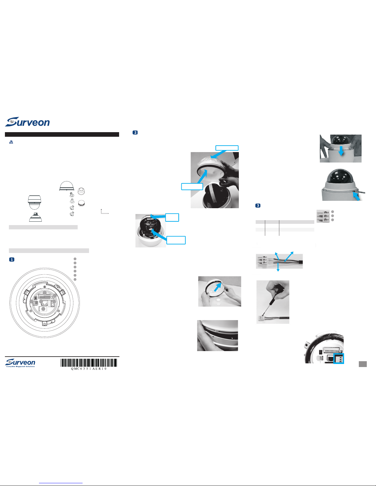
1. Unpack the dome package and take out the dome body.
2. Remove the plastic wrapping on the dome cover.
3. Remove the Styrofoam sheet from the inside of the dome cover.
Preparation for Dome Camera Setup
Plastic wrapping
Styrofoam sheet
4. Remove the tape and lens cap on the camera.
5. Remove the two screws on the dome cover.
6. Attach the dome cover. Before doing that, apply some lubricant
on the cover’s water-proof rubber to make the installation
process smoother.
Note that the tiny protrusion on the dome cover must align
with one of the four holes on the dome body.
Tape
Lens cap
Blue or Black
Brown or White
Yellow/Green or Green
7. Gently pressure the dome cover downward with two hands
on the side of it.
8. Use one M3 Screw and the original two screws to screw the
dome cover and camera body together.
1 LAN Connector
2
3 Power Connector Slot
4
5 Reset Button
6 Audio In/Out Connector
Alarm In/Out Connector
Micro SD Card Slot
1. Connect the power wires of AC adapter with the power connector. Please check the colors of the
power wires carefully, and screw them with the connector properly.
2. Insert the power connector into the power connector slot.
1/4
Pin definitions of the power connector:
Connecting Power
Camera Cable Connections
1
2
3
1 AC 24-
Pin Definition
Blue or Black
2 FG Yellow/Green or Green
3 AC 24+ Brown or White
Color of Power Wire Connected
1/4
2/4
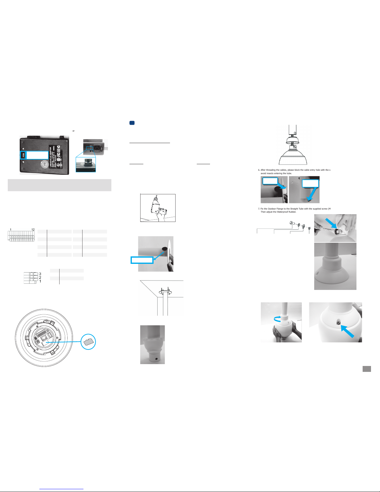
6. After threading the cables, please block the cable entry hole with the supplied sponge(s) to
avoid insects entering the tube.
4. Fit the Waterproof Rubber to the Straight Tube. (You may turn the Waterproof Rubber inside out,
which is shown in the picture below, to make the fitment easier.)
7. Fix the Outdoor Flange to the Straight Tube with the supplied screw (M8x12) and washers.
Then adjust the Waterproof Rubber.
5. Thread the cables through the Straight Tube and the Outdoor Flange.
Ceiling Mounting
Dome Camera Installation
4
Package Contents of Ceiling Mounting Kit
●
M8x12 Screw x1
●
Spring Washer-8 x1
●
Pendant Tube Washer x1
●
Rubber Washer-8 x1
●
Sponge x2
Tools Needed
●
Electric Drill
●
Screw Driver
●
Wrench Kit
Items Needed
●
Waterproof Rubber x1 (provided with the package of the
camera)
●
M5 Screw x1 (provided with the package of the camera)
●
Screws and Screw Anchors for fixing the Straight Tube onto
the ceiling (provided by users)
1. Ensure that the ceiling can support the weight of the Dome Camera and Straight Tube.
2. Make one cable entry hole and four screw holes on the ceiling with the electric drill.
Otherwise, users can remove the Cable Entry Cover on the Straight Tube to place the cables.
3. Fix the Straight Tube to the ceiling with screws and screw anchors.
Sponge
Sponge
8. Mount the Dome Camera to the Outdoor Flange. Rotate the dome body and make sure the thread holes
on the Lock Screw Plate and Outdoor Flange are aligned. Then screw the M5 Screw.
Please go to page 4 for software installation.
Cable Entry Cover
Connecting Power with Optional AC Adapter
Note: (1) Contact your dealer for purchasing the adapters. (2) If the adapter doesn’t work, please
check whether the fuses inside are blown or not. You can change the fuses yourself according
to the specifications: S504-1.6A/250V for 110V input; S504-1A/250V for 220V input.
3. Adjust the power selector according to the practical local power
voltage, and connect the power cord with the adapter and power
outlet
Connecting LAN Cable
1. Connect one end of the LAN cable to the LAN connector of the network Speed Dome Camera, and the
other end of the cable to the network switch or PC.
2. Check the status of the link indicator and activity indicator LEDs; if the LEDs are unlit, please check
LAN connection.
1. Make sure the golden finger of the Micro SD card is facing downwards.
2. Push the Micro SD card into the card slot until you hear a click sound.
For ceiling mounting, please look into Ceiling Mounting Section in this page, and for wall
mounting, please go to Wall Mounting Section in page3.
Applying Alarm I/O (Optional)
Applying Audio (Optional)
Inserting the Micro SD Card (Optional)
The network Speed Dome Camera supports 4 digital alarm inputs and 2 digital alarm outputs. Please
make sure the alarm connections are properly wired before starting to configure alarm related settings.
Please refer to the pin definition table below for alarm system wiring.
Set up the audio according to the audio
pin definition.
1 ALARM_OUT_NO_1
Pin Definition
Power selector
2 ALARM_OUT_NC_1
3 ALARM_OUT_COM_1
4 GND
5 ALARM_OUT_NO_2
6 ALARM_OUT_NC_2
7 ALARM_OUT_COM_2
Pin Definition
8 GND
9 ALARM_IN_4
10 ALARM_IN_3
11 ALARM_IN_2
12 ALARM_IN_1
1 LINE_OUT
Pin Definition
2 GND
3 LINE_IN
M8x12
screw
Pendant
tube washer
Spring
washer
Rubber
washer
 Loading...