

Surveon CAM4xxx Series, CAM4110, CAM4160, CAM4210, CAM4220 User Manual
...
CAM4xxx Series
User Manual
Release 1.1

2
All Rights Reserved © Surveon Technology 2012
Copyright Statement
No part of this publication may be reproduced, transmitted, transcribed,
stored in a retrieval system, or translated into any language or computer
language, in any form or by any means, electronic, mechanical, magnetic,
optical, chemical, manual or otherwise, without the prior written consent of
Surveon Technology Inc.
Disclaimer
Surveon Technology makes no representations or warranties with respect to
the contents hereof and specifically disclaim any implied warranties of
merchantability or fitness for any particular purpose. Furthermore, Surveon
Technology reserves the right to revise this publication and to make changes
from time to time in the content hereof without obligation to notify any
person of such revisions or changes. Product specifications are also subject to
change without notice.
Trademarks
Surveon and Surveon logo are trademarks of Surveon Technology Inc. Other
names prefixed with “SMR” and “EMR” are trademarks of Surveon Technology
Inc.
Microsoft Windows and Windows are registered trademarks of Microsoft
Corporation.
Linux is a trademark of Linux Torvalds.
Solaris and Java are trademarks of Sun Microsystems, Inc.
All other names, brands, products or services are trademarks or registered
trademarks of their respective owners.

3
Revision History
Ver
sion Description Date
1.0 Initial release: All the CAM4xxx series
models are put into this manual; both
hardware and software aspects are
covered.
April 2012
1.1 New model: CAM4311/4371 are added. June 2012

4
Table of Contents
Copyright Statement .........................................................................2
Revision History ...............................................................................3
Table of Contents .............................................................................4
Safety Precautions............................................................................8
Device Site Recommendations..............................................................8
Chapter 1. Product Overview...............................................................9
1.1. Network Camera Introduction .....................................................9
1.2. Features and Benefits...............................................................9
1.3. Technical Specifications .......................................................... 11
Model List for CAM4xxx Series........................................................ 11
Specifications for CAM41xx Series ................................................... 11
Specifications for CAM42xx Series ................................................... 13
Specifications for CAM431x Series ................................................... 15
Specifications for CAM436x Series ................................................... 17
Specifications for CAM437x Series ................................................... 19
Chapter 2. Hardware Overview .......................................................... 21
2.1. Overview............................................................................. 21
Side View ................................................................................ 21
Indoor: Fixed Lens (CAM4110/4210/4310/4311).............................. 21
Indoor: Varifocal Lens (CAM4220)............................................... 21
Outdoor (CAM4160/4260/4360/4361/4365/4371) ............................ 21
Top View and Bottom View........................................................... 22
Indoor (CAM4110/4210/4220/4310/4311) ..................................... 22
Outdoor (CAM4160/4260/4360/4361/4365/4371) ............................ 22
2.2. Functions ............................................................................ 23
2.3. Installation........................................................................... 27
Installing the Dome Camera .......................................................... 27
2.4. Camera Deployment ............................................................... 31

5
2.5. Before You Start.................................................................... 31
Chapter 3. Connecting to the Network Camera....................................... 32
3.1. Connecting with a Web Browser ................................................ 33
Obtaining IP address through the IP Utility......................................... 33
Connecting to the Network Camera................................................. 33
Logging into the System............................................................... 34
Installing Active X Components in Internet Explorer.............................. 34
Logging Out of the System............................................................ 35
Using the Help Interface .............................................................. 35
3.2. Connecting with an RTSP Player ................................................ 37
Connecting with a Mobile Device RTSP Player ..................................... 37
Chapter 4. Configuration through the Web Interface................................ 38
4.1. Interface Layout.................................................................... 40
Control Descriptions ................................................................... 41
4.2. Settings............................................................................... 43
General .................................................................................. 43
Basic Settings ...................................................................... 43
User Account....................................................................... 45
Date & Time ....................................................................... 48
Network ................................................................................. 50
Network Configuration ........................................................... 50
Port Settings ....................................................................... 52
UpnP ................................................................................ 54
Video & Audio Settings ................................................................ 55
Basic Settings ...................................................................... 55
Image Appearance Settings ...................................................... 56
Image Appearance (for CAM4110/4160) ....................................... 56
Image Appearance (for CAM4210/4220/4260) ................................ 60
Image Appearance (for CAM4310)............................................... 63
Image Appearance (for CAM4311)............................................... 67
Image Appearance (for CAM4360/4365) ....................................... 70

6
Image Appearance (for CAM4361/4371) ....................................... 75
Video Streams ..................................................................... 80
Audio Settings ..................................................................... 85
PTZ ....................................................................................... 86
Recording................................................................................ 87
Recording Basic Settings ......................................................... 87
Recorded File Management...................................................... 88
Event Notification...................................................................... 90
Event Server ....................................................................... 90
Motion Detection .................................................................. 92
Tampering Detection ............................................................. 94
DI & DO ............................................................................. 95
Event Settings ..................................................................... 97
System .................................................................................. 103
MicroSD Card Management...................................................... 103
System Status ..................................................................... 104
System Log ........................................................................ 105
Firmware Upgrade ............................................................... 106
Emergency Recovery Procedure................................................ 107
Resetting to Factory Default Settings ......................................... 107
Export/Import & Reboot ........................................................ 109
Chapter 5. Configuration through the IP Utility..................................... 110
5.1. Overview........................................................................... 112
5.2. Installing the IP Utility .......................................................... 112
5.3. IP Utility Basics ................................................................... 114
Starting the IP Utility................................................................. 114
IP Utility Main Screen................................................................. 114
Exiting the IP Utility .................................................................. 114
5.4. Camera Actions ................................................................... 115
Search................................................................................... 115
Login .................................................................................... 115

7
Properties .............................................................................. 116
Delete from Tool ...................................................................... 117
Select All ............................................................................... 118
Rebooting Camera .................................................................... 118
Set IP.................................................................................... 119
Link to Camera Web Interface ...................................................... 120
Link to Camera ................................................................... 120
Link to Camera User Manager .................................................. 120
Clearing and Setting Status.......................................................... 121
Clear New Status ................................................................. 121
Set New Status.................................................................... 121
5.5. Camera Group Actions........................................................... 123
Add Group.............................................................................. 123
Delete Group........................................................................... 123
Rename Group......................................................................... 124
Move to Group ......................................................................... 125
Copy to Group ......................................................................... 126
5.6. Configuration Settings........................................................... 127
Download Configuration.............................................................. 127
Update Configuration................................................................. 128
5.7. Firmware Actions ................................................................ 129
Download Firmware................................................................... 129
Update Firmware...................................................................... 129
5.8. Focus Tool ......................................................................... 131
8
Safety Precautions
Electric Shock Warning
This equipment may cause electric shocks if not handled properly.
Access to this equipment should only be granted to trained operators
and maintenance personnel who have been instructed of, and fully
understand the possible hazardous conditions and the consequences of
accessing non-field-serviceable units such as the power supplies.
The system must be unplugged before moving, or in the even that it
becomes damaged.
Reliable Grounding
Particular attention should be given to prepare reliable grounding for the
power supply connection. It is suggested to use a direct connection to the
branch circuit. Check for proper grounding before powering on the device.
Overloading Protection
The device should be installed according to specifications. Provide a suitable
power source with electrical overload protection. Do not overload the AC
supply branch circuit that provides power to the device.
ESD Precautions
Please observe all conventional anti-ESD methods while handling the device.
The use of a grounded wrist strap and an anti-static work pad are
recommended. Avoid dust and debris in your work area.
Device Site Recommendations
The device should be installed according to specifications. This device should
be operated at a site that is:
Clean, dry, and free of excessive airborne particles.
Well-ventilated and away from heat sources such as direct sunlight
and radiators.
Clear of vibration or physical shock.
Away from strong electromagnetic fields produced by other devices.
Available with properly grounded wall outlet for power. In regions
where power sources are unstable, apply surge suppression.
Available with sufficient space behind the device for cabling.

9
Chapter 1. Product Overview
1.1. Network Camera Introduction
CAM4xxx series are professional network cameras that use Internet Protocol (IP) to
transmit video streams and control signals over networks. Capable of operating
over both LANs and WANs, they provide a complete budget-conscious remote
surveillance solution that are ultra clear and highly integrated. CAM4xxx series
combine a user-friendly interface and simplified installation with a powerful
feature set to provide users an easy upgrade path to new digital surveillance
system in a virtual environment. These highlights make CAM4xxx series ideal
choices for environments that require remote surveillance or video transmission.
1.2. Features and Benefits
4xxx series IP camera is a cutting-edge digital video transmission device. It can
compress and transmit real-time images of outstanding quality using a
reasonable amount of bandwidth through a standard TCP/IP network. The
following features make this IP camera an outstanding choice when building an
intelligent IP surveillance system:
High Video Quality
High image quality is essential in security surveillance applications. It is
important to be able to clearly capture an incident in progress and
identify persons or objects involved. A network camera gives exceptional
video quality, even greater than that of traditional analog cameras, which
means that more detail or larger areas can be covered.
H.264/MPEG-4/MJPEG Compression
Motion JPEG, MPEG-4, and H.264 (also known as MPEG-4 Part 10/AVC),
each employ different techniques to reduce the amount of data
transferred and stored in a network video system. Network cameras that
support multiple compression standards are ideal for maximum flexibility
and integration possibilities.

10
Dual Streaming
Dual-stream design enables simultaneous support of real-time video
monitoring, video recording, or mobile viewing applications which require
different resolutions, compression formats and frame rates.
MicroSD/SDHC card slot
IP surveillance relies on network connectivity, making it susceptible to
attacks on the network between the camera and recording facilities. With
onboard recording capability, our network cameras can truly be online
24/7. The microSD/SDHC card slot design ensures sufficient recording
capacity for an over-weekend period even at full frame rate and high
resolution.
Tampering Detection
This is an intelligent video analytics application available only in selected
network cameras in the market. When a camera is manipulated in any way
(e.g. accidental redirection, blocking, defocusing, spray-painted, covered
or damaged), it can automatically trigger recording and alert notifications.
Power-over-Ethernet
The built-in Power-over-Ethernet support reduces cabling and installation
costs, and enables users to consolidate power facilities for higher
reliability. With PoE, a camera can still operate in the event of a power
failure if it is connected to a centralized backup power with an
Uninterruptible Power Supply.
IR LED Illuminators
With the built-in IR illuminators, the camera is capable of working in low
light conditions, with a range up to 15m.

11
1.3. Technical Specifications
Model List for CAM4xxx Series
CAM4110
D1 IP Fixed Dome
CAM4160 D1 D/N Outdoor IP Fixed Dome
CAM4210 1.3M IP Fixed Dome
CAM4220 1.3M D/N IP Fixed Dome
CAM4260 1.3M D/N Outdoor IP Fixed Dome
CAM4310 2M IP Fixed Dome
CAM 4311 2M D/N IP Fixed Dome
CAM4360 2M D/N Outdoor IP Fixed Dome
CAM4361
2M WDR D/N Outdoor IP Fixed Dome
CAM4365
3M D/N Outdoor IP Fixed Dome
CAM4371
2M WDR D/N Outdoor IP Fixed Dome
Specifications for CAM41xx Series
Model Name CAM4110 CAM4160
Description D1 IP Fixed Dome D1 D/N Outdoor IP Fixed Dome
Image Sensor 1/3.2" D1 progressive color CMOS
Lens 4.2 mm, F1.8 (default) 2.8 - 11 mm varifocal lens, F1.4
SNR 50dB
WDR N/A
Day/Night ICR Dual Band Filter Yes
IR LED Yes (15M) Yes (30M)
Min Illumination
0 Lux (IR LEDs on)
0.3 Lux @ F1.8 (Color)
Iris Control N/A
Viewing Angle
Diagonal:89°
Horizontal:71°
Vertical:49.5°
Diagonal: 122°~35°
Horizontal: 96°~28°
Vertical: 72°~21°
Camera Angle
Adjustment
Pan 0º~340º
Tilt 30º~90º
Pan/Tilt/Zoom
Functionalities
N/A
Shutter Time 1/60~1/10,000s
Video Compression H.264/MPEG-4/MJPEG
Resolution Up to 720 x 480

12
Video FPS
30 fps at D1 (720 x 480)
30 fps at VGA (640 x 480)
30 fps at QVGA (320 x 240)
Video Control
AGC (Auto Gain Control),
AWB (Auto White Balance),
AES (Auto Electronic Shutter),
BLC (Back Light Compensation),
Image Adjustment
Video Stream Dual stream at H.264, MPEG-4, and MJPEG simultaneously
Bit Rate 64K ~ 6Mbps, VBR, CBR, controller frame rate and quality
Intelligent Video
Motion Detection,
Tampering Detection
(blocked, redirected, defocused, or spray-painted)
Video Jack N/A
Audio 2 Way Audio, Built-in MIC 2 Way Audio
Audio Compression 32KHz, ADPCM
Audio Input/Output 3.5mm phone jack
Alarm In/Out 2/1, terminal block
Video Buffer 5 second pre-alarm, 30 second post-alarm
Event Action
Send snapshot or video clip by FTP or email, record to NAS, record to local
storage, trigger DO
Supported Protocols
IPv4, ARP, TCP, UDP, ICMP, DHCP, NTP, DDNS, SMTP, FTP, HTTP, CIFS,
PPPoE, UPnP, RTP, RTSP, RTCP, 3GPP
Ethernet 10/100 Base-T / RJ45
Local Storage
microSD/SDHC x 1
(Class 2/Class 4/Class 6)
RS-485 1 (2 pin on terminal block)
USB N/A
SDK SDK 2.0
OS Microsoft Windows XP/Vista/7
Browser Microsoft IE 6.0 or above
Software VMS 2.4.1
Temperature
Operation: -10~50°C (14~122°F)
Storage: -30~60°C (-22~140°F)
Operation: -25~50°C (-13~122°F)
Storage: -30~60°C (-22~140°F)
Humidity 5 to 90%
Power
12VDC 1.5A;PoE (IEEE 802.3af) with Class 3
Power Consumption Max. 7.5W
Max. 7.5W (w/o Heater)
Max. 12W (w/ Heater)
Dimension
ø128.8mm x 98.6mm (H)
ø5.07” x 3.88”(H)
ø144mm x 116mm (H)
ø5.67” x 4.57”(H)
Weight
Net: 620g (1.37lb.)
Gross: 1290g (2.85lb.)
Net: 1,260g (2.78lb.)
Gross: 1,930g (4.27lb.)
Certification
Safety: LVD
EMC: FCC, CE
Safety: LVD
EMC: FCC, CE
IP66

13
Specifications for CAM42xx Series
Model Name CAM4210 CAM4220 CAM4260
Description 1.3M IP Fixed Dome 1.3M D/N IP Fixed Dome
1.3M D/N Outdoor IP Fixed
Dome
Image Sensor 1/3" 1.3 megapixel progressive scan CMOS
Lens 4.2 mm, F1.8 (default) 2.8 - 11 mm varifocal lens, F1.4
WDR N/A
Day/Night ICR Dual Band Filter Yes
IR LED Yes (15M) Yes (30M)
Min Illumination
0 Lux (IR LEDs on)
3 Lux @ F1.0 (Color)
Iris Control N/A Manual IRIS
Viewing Angle
Diagonal:89°
Horizontal:71°
Vertical:49.5°
Diagonal: 122°~35°
Horizontal: 96°~28°
Vertical: 72°~21°
Camera Angle
Adjustment
Pan 0º~340º
Tilt 30º~90º
Pan/Tilt/Zoom
Functionalities
N/A
Shutter Time 1/5~1/15,000 s
Video Compression H.264/MPEG-4/MJPEG
Resolution Up to 1280 x 1024
Video FPS
15 fps at SXGA (1280 x 1024)
15 fps at HD720 (1280 x 720)
30 fps at VGA (640 x 480)
30 fps at QVGA (320 x 240)
Video Control
AGC (Auto Gain Control),
AWB (Auto White Balance),
AES (Auto Electronic Shutter),
BLC (Back Light Compensation),
Image Adjustment
Video Stream Dual stream at H.264, MPEG-4, and MJPEG simultaneously
Bit Rate 64K ~ 6Mbps, VBR, CBR, controller frame rate and quality
Intelligent Video
Motion Detection,
Tampering Detection
(blocked, redirected, defocused, or spray-painted)
Video Jack N/A
Audio 2/1 2 Way Audio, Built-in MIC 2 Way Audio
Audio Compression 32KHz, ADPCM
Audio Input/Output 3.5mm phone jack
Alarm In/Out 2/1, terminal block
Video Buffer 5 second pre-alarm, 30 second post-alarm

14
Event Action
Send snapshot or video clip by FTP or email, record to NAS, record to local storage, trigger
DO
Supported Protocols
IPv4, ARP, TCP, UDP, ICMP, DHCP, NTP, DDNS, SMTP, FTP, HTTP, CIFS, PPPoE, UPnP, RTP,
RTSP, RTCP, 3GPP
Ethernet 10/100 Base-T / RJ45
Local Storage
microSD/SDHC x 1
(Class 2/Class 4/Class 6)
RS-485 1 (2 pin on terminal block)
USB N/A
SDK SDK 2.0
OS Microsoft Windows XP/Vista/7
Browser Microsoft IE 6.0 or above
Software VMS 2.4.1
Temperature
Operation: -10~50°C (14~122°F)
Storage: -30~60°C (-22~140°F)
Operation: -25~50°C (-
13~122°F)
Storage: -30°C ~ 60°C (-
22°F~140°F)
Humidity 5 to 90%
Power
12VDC 1.5A;PoE (IEEE 802.3af) with Class 3
Power Consumption Max. 7.5W
Max. 7.5W (w/o Heater)
Max. 12W (w/ Heater)
Dimension
ø128.8mm x 98.6mm (H)
ø5.07” x 3.88”(H)
ø128.8mm x 115mm (H)
ø5.07” x 4.52" (H)
ø144mm x 116mm (H)
ø5.67” x 4.57”(H)
Weight
Net: 620g (1.37lb.)
Gross: 1290g (2.85lb.)
Net: 700g (1.54lb.)
Gross: 1370g (3.00lb.)
Net: 1,260g (2.78lb.)
Gross: 1,930g (4.27lb.)
Certification
Safety: LVD
EMC: FCC, CE
Safety: LVD
EMC: FCC, CE
IP66

15
Specifications for CAM431x Series
Model Name CAM4310 CAM4311
Description 2M IP Fixed Dome 2M D/N IP Fixed Dome
Image Sensor 1/2.7" 2 megapixel progressive scan CMOS
Lens 4.2 mm, F1.8 (default) 4.0 mm, F2.0
SNR 48dB
WDR N/A
Yes
Day/Night ICR N/A
Yes
IR LED N/A
Yes (10M)
Min Illumination
0.5 Lux @ F1.0
0.5 Lux @ F1.0 (Color)
0.01 Lux @ F1.2 (B/W)
0.1 Lux @ F1.2 (Color)
Iris Control N/A
Viewing Angle
Diagonal:89°
Horizontal:71°
Vertical:49.5°
Diagonal: 101.7°°
Horizontal: 87.7°°
Vertical: 48°
Camera Angle
Adjustment
Pan 0º~340º
Tilt 30º~90º
Pan/Tilt/Zoom
Functionalities
N/A
Shutter Time 1/30~1/50,000 s
Video
Compression
H.264/MPEG-4/MJPEG
Resolution Up to 1920 x 1080
Video FPS
25 fps at 1080P (1920 x 1080)
30 fps at SXGA (1280 x 1024)
30 fps at HD720 (1280 x 720)
30 fps at D1 (720 x 480)
30 fps at VGA (640 x 480)
30 fps at QVGA (320 x 240)
25 fps at 1080P (1920 x 1080)
30 fps at SXGA (1280 x 1024)
30 fps at HD720 (1280 x 720)
30 fps at D1 (720 x 480)
30 fps at VGA (640 x 480)
30 fps at QVGA (320 x 240)
Video Control
AGC (Auto Gain Control),
AWB (Auto White Balance),
AES (Auto Electronic Shutter),
BLC (Back Light Compensation),
HLC (High Light Compensation),
3D Noise Reduction,
Defog,
Image Adjustment
Video Stream Dual stream at H.264, MPEG-4, and MJPEG simultaneously
Bit Rate 64K ~ 6Mbps, VBR, CBR, controller frame rate and quality
Intelligent Video Motion Detection
Video Jack N/A
Audio 2 Way Audio, Built-in MIC N/A
Audio
Compression
32KHz, ADPCM

16
Audio
Input/Output
3.5mm phone jack
Alarm In/Out N/A
Video Buffer 5 second pre-alarm, 30 second post-alarm
Event Action
Send snapshot or video clip by FTP or email, record to NAS, record to local
storage, trigger DO
Supported
Protocols
IPv4, ARP, TCP, UDP, ICMP, DHCP, NTP, DDNS, SMTP, FTP, HTTP, CIFS, PPPoE,
UPnP, RTP, RTSP, RTCP, 3GPP
Ethernet 10/100 Base-T/RJ45
Local Storage
microSD/SDHC x 1
(Class 2/Class 4/Class 6)
RS-485 1 (2 pin on terminal block)
USB N/A
SDK Surveon SDK 2.0
OS Microsoft Windows XP/Vista/7
Browser Microsoft IE 6.0 or above
Software Surveon VMS 2.4.1
Temperature
Operation: -10~50°C (14~122°F)
Storage: -30~60°C (-22~140°F)
Humidity 5 to 90%
Power
12VDC 1.5A;PoE (IEEE 802.3af) with Class 3
Power
Consumption
Max. 7.5W
Dimension
ø128.8mm x 98.6mm (H)
ø5.07” x 3.88”(H)
Weight
Net: 620g (1.37lb.)
Gross: 1290g (2.85lb.)
Certification
Safety: LVD
EMC: FCC, CE

17
Specifications for CAM436x Series
Model Name CAM4360 CAM4361 CAM4365
Description
2M D/N Outdoor
IP Fixed Dome
2M WDR D/N Outdoor
IP Fixed Dome
3M D/N Outdoor
IP Fixed Dome
Image Sensor 1/2.7" 2 megapixel progressive scan CMOS
1/2.8" 3 megapixel SONY low
light CMOS
Lens 3~10 mm motor lens, F1.3 2.8~11 mm varifocal lens, F1.4
3~10 mm motor lens, F1.3
SNR 48dB
WDR N/A Yes
Day/Night ICR Yes
IR LED Yes (15M) Yes (20M)
Yes (15M)
Min Illumination
0 Lux (IR LEDs on)
0.5 Lux @ F1.0 (Color)
0.01 Lux @ F1.2 (B/W)
0.1 Lux @ F1.2 (Color)
0 Lux (IR LEDs on)
0.1 Lux @ F1.2 (Color)
Iris Control DC drive
Viewing Angle
Diagonal: 122°~35°
Horizontal: 96°~28°
Vertical: 72°~21°
Diagonal: 99°~37.3°
Horizontal: 79.3°~29.8°
Vertical: 59.5°~22.4°
Diagonal: 122°~35°
Horizontal: 96°~28°
Vertical: 72°~21°
Camera Angle
Adjustment
Pan 0º~340º
Tilt 30º~90º
Pan/Tilt/Zoom
Functionalities
N/A
Shutter Time 1/7.5 ~ 1/100,000s
1/30~1/50,000s 1/7.5 ~ 1/100,000s
Video Compression H.264/MPEG-4/MJPEG
Resolution Up to 1920 x 1080 Up to 2048 x 1536
Video FPS
25 fps at 1080P (1920 x 1080)
30 fps at SXGA (1280 x 1024)
30 fps at HD720 (1280 x 720)
30 fps at D1 (720 x 480)
30 fps at VGA (640 x 480)
30 fps at QVGA (320 x 240)
15 fps at QXGA (2048 x 1536)
25 fps at 1080P (1920 x 1080)
30 fps at SXGA (1280 x 1024)
30 fps at HD720 (1280 x 720)
30 fps at D1 (720 x 480)
30 fps at VGA (640 x 480)
30 fps at QVGA (320 x 240)
Video Control
AGC (Auto Gain Control),
AWB (Auto White
Balance),
AES (Auto Electronic
Shutter),
BLC (Back Light
Compensation),
HLC (High Light
Compensation),
3D Noise Reduction,
Defog,
Image Adjustment
AGC (Auto Gain Control),
AWB (Auto White Balance),
AES (Auto Electronic Shutter),
BLC (Back Light Compensation),
HSLC (High Suppression
Backlight Compensation),
3D Noise Reduction, Defog,
Image Adjustment
AGC (Auto Gain Control),
AWB (Auto White Balance),
AES (Auto Electronic
Shutter),
BLC (Back Light
Compensation),
Image Adjustment
Video Stream Dual stream at H.264, MPEG-4, and MJPEG simultaneously
Bit Rate 64K ~ 6Mbps, VBR, CBR, controller frame rate and quality

18
Intelligent Video Motion Detection
Motion Detection,
Tampering Detection (blocked,
redirected,
Motion Detection
Video Jack N/A
Yes (BNC)
N/A
Audio 2 Way Audio N/A
2 Way Audio
Audio Compression 32KHz, ADPCM
Audio Input/Output 3.5mm phone jack
Alarm In/Out 2/1, terminal block
N/A 2/1, terminal block
Video Buffer 5 second pre-alarm, 30 second post-alarm
Event Action
Send snapshot or video clip by FTP or email, record to NAS, record to local storage, trigger
DO
Supported Protocols
IPv4, ARP, TCP, UDP, ICMP, DHCP, NTP, DDNS, SMTP, FTP, HTTP, CIFS, PPPoE, UPnP, RTP,
RTSP, RTCP, 3GPP
Ethernet 10/100 Base-T / RJ45
Local Storage
microSD/SDHC x 1
(Class 4/Class 6 only)
RS-485 1 (2 pin on terminal block)
N/A 1 (2 pin on terminal block)
USB N/A
SDK SDK 2.0
OS Microsoft Windows XP/Vista/7
Browser Microsoft IE 6.0 or above
Software VMS 2.4.1
Temperature
Operation: -25~ 50°C (-13~122°F)
Storage: -30~60°C (-22~140°F)
Humidity 5 to 90%
Power
12VDC 1.5A;PoE (IEEE 802.3af) with Class 3
Power Consumption
Max. 7.5W (w/o Heater)
Max. 12W (w/ Heater)
Max. 8W (w/o Heater )
Max. 35W (w/ Heater )
Max. 7.5W (w/o Heater)
Max. 12W (w/ Heater)
Dimension
ø144mm x 116mm (H)
ø5.67” x 4.57”(H)
Weight
Net: 1,260g (2.78lb.)
Gross: 1,930g (4.27lb.)
Certification
Safety: LVD
EMC: FCC, CE
IP66

19
Specifications for CAM437x Series
Model Name CAM4371
Description
2M WDR D/N Outdoor
IP Fixed Dome
Image Sensor 1/2.8" 2 megapixel SONY Exmor CMOS (CAM4371)
Lens 3~9 mm moto lens, F1.2
SNR 48dB
WDR Yes
Day/Night ICR Yes
IR LED
Yes (20M)
Min Illumination
0.01 Lux @ F1.2 (B/W)
0.1 Lux @ F1.2 (Color)
Iris Control DC drive
Viewing Angle
Diagonal: 148.4°- 43.8°
Horizontal: 121.2°- 38.1°
Vertical: 62.1° - 21.3°
(CAM4371)
Camera Angle Adjustment
Pan 0º~340º
Tilt 30º~90º
Pan/Tilt/Zoom
Functionalities
N/A
Shutter Time
1/30~1/50,000s
Video Compression H.264/MPEG-4/MJPEG
Resolution Up to 1920 x 1080
Video FPS
25 fps at 1080P (1920 x 1080)
30 fps at SXGA (1280 x 1024)
30 fps at HD720 (1280 x 720)
30 fps at D1 (720 x 480)
30 fps at VGA (640 x 480)
30 fps at QVGA (320 x 240)
Video Control
AGC (Auto Gain Control),
AWB (Auto White Balance),
AES (Auto Electronic Shutter),
BLC (Back Light Compensation),
HSLC (High Suppression Backlight Compensation),
3D Noise Reduction, Defog,
Image Adjustment
Video Stream
Dual stream at H.264, MPEG-4, and MJPEG
simultaneously
Bit Rate 64K ~ 6Mbps, VBR, CBR, controller frame rate and quality
Intelligent Video
Motion Detection,
Tampering Detection (blocked, redirected,
Video Jack Yes (BNC)

20
Audio
2 Way Audio
Audio Compression 32KHz, ADPCM
Audio Input/Output 3.5mm phone jack
Alarm In/Out
N/A
Video Buffer
5 second pre-alarm,
30 second post-alarm
Event Action
Send snapshot or video clip by FTP or email, record to NAS,
record to local storage, trigger DO
Supported Protocols
IPv4, ARP, TCP, UDP, ICMP, DHCP, NTP, DDNS, SMTP, FTP,
HTTP, CIFS, PPPoE, UPnP, RTP, RTSP, RTCP, 3GPP
Ethernet 10/100 Base-T / RJ45
Local Storage microSD/SDHC x 1 (Class 2/Class 4/Class 6)
RS-485
N/A
USB N/A
SDK SDK 2.0
OS Microsoft Windows XP/Vista/7
Browser Microsoft IE 6.0 or above
Software VMS 2.4.1
Temperature
Operation: -25~ 50°C (-13~122°F)
Storage: -30~60°C (-22~140°F)
Humidity 5 to 90%
Power
12VDC 1.5A;PoE (IEEE 802.3af) with Class 3
Power Consumption
Max. 8W (w/o Heater )
Max. 35W (w/ Heater )
Dimension
ø144mm x 116mm (H)
ø5.67” x 4.57”(H)
Weight
Net: 1,260g (2.78lb.)
Gross: 1,930g (4.27lb.)
Certification
Safety: LVD
EMC: FCC, CE
IP66

21
Chapter 2. Hardware Overview
2.1. Overview
Side View
Indoor: Fixed Lens (CAM4110/4210/4310/4311)
Indoor: Varifocal Lens (CAM4220)
Outdoor (CAM4160/4260/4360/4361/4365/4371)
22
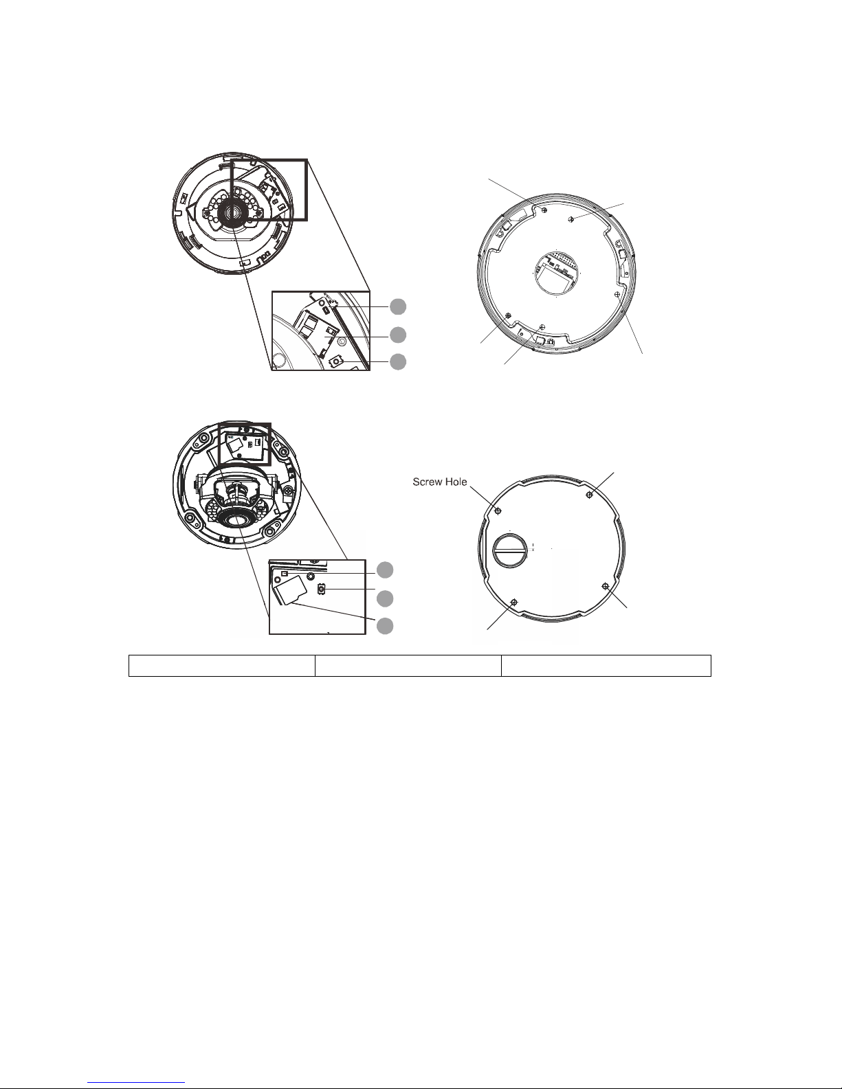
Top View and Bottom View
Indoor (CAM4110/4210/4220/4310/4311)
Screw Hole
Screw Hole
Screw Hole
Screw Hole
Screw Hole
1
3
2
Outdoor (CAM4160/4260/4360/4361/4365/4371)
Screw Hole
Screw Hole
Screw Hole
1
2
3
1. Status LED Indicator 2. Reset Button 3. MicroSD/SDHC Card Slot
23
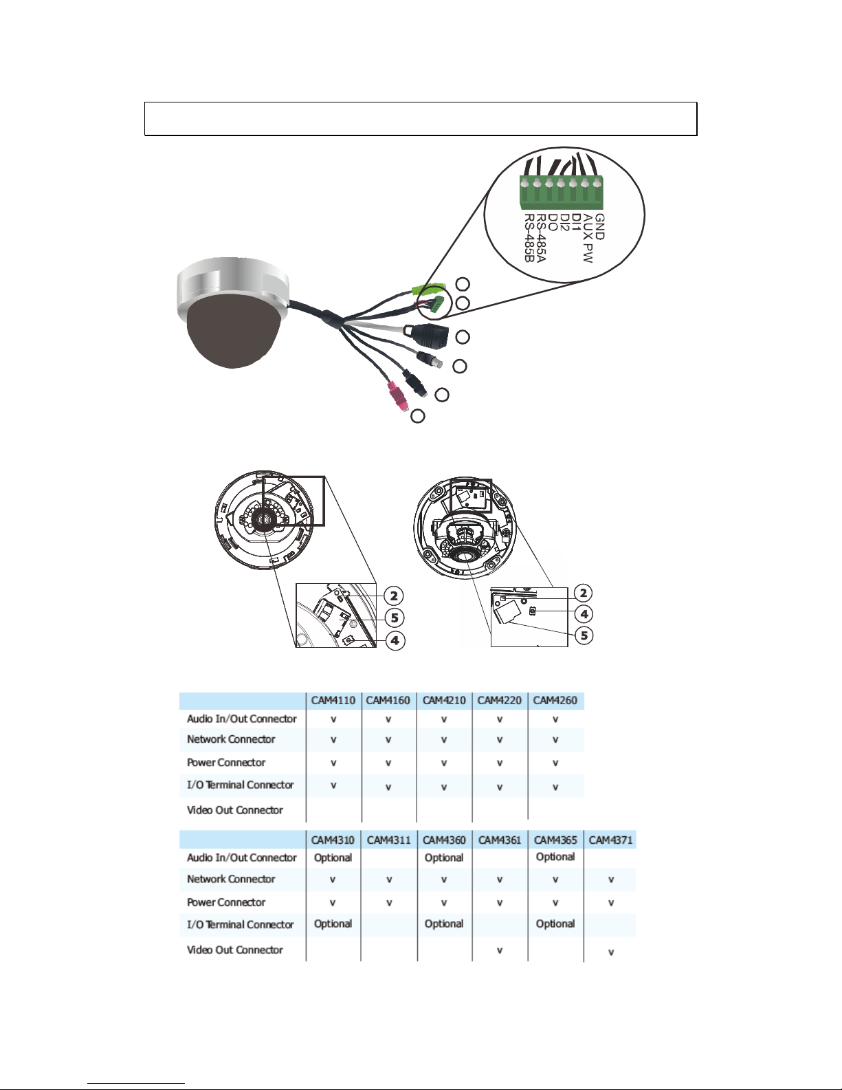
2.2. Functions
7
1
1
8
6
3
Indoor Outdoor
Please look into the following table for cable options:

24
1. Audio In/Out Connector
Audio In/Out are both for 3.5mm jacks. Audio-in provides for an external
mono microphone. Audio out can be connected to a public address
system or an active speaker with a built-in amplifier. A pair of
headphones can also be attached.
Note: Built-in microphone can also be used for certain models. Please
refer to Audio Setting section for details.
2. Status LED Indicator
The LED will light up after the camera has successfully completed the
boot process. The Status LED indicator in the rear of the camera can be
set to light whenever the unit is accessed, or be shut off.
Green
Shows steady green for normal operation, flashing
when the camera is accessed.
Note: The Status LED can be configured to be
unlit.
Steady during startup, reset to factory default or
when restoring settings.
Amber
Flashes every 0.2 sec during firmware upgrade.
(On:0.2 sec, Off: 0.2 sec)
Note: Startup or reboot may have failed if the status LED shows
steady amber for over 1 minute.
Status
LED
(rear)
Unlit No network connection.
3. Video Out Connector (CAM4361 only)
Video Out Connector is used for connecting monitors with BNC ports.
4. Reset Button
Pressing the reset button will restore the camera to its factory default
settings, as described in Resetting to the Factory Default Settings.
5. microSD/SDHC Card Slot
The microSD/SDHC card slot can be used for local recording and
firmware upgrade.
Note: Apacer 4GB Class 6/Transcend 8GB Class 6/Kingston 16GB Class 2,
SanDisk 16GB Class 2/SanDisk 32GB Class 4 MicroSDHC card are
recommended, since they have passed the SD Card QVL (Qualified
Vender List) test.
6. Network Connector

25
The camera connects to the network via a standard RJ-45 network
connector. The camera detects the speed of the local network
(10/100BaseT). The camera also supports PoE (Power-over-Ethernet), and
can be powered directly through the network cable.
7. Power Connector
The power connector is provided for solutions without PoE.
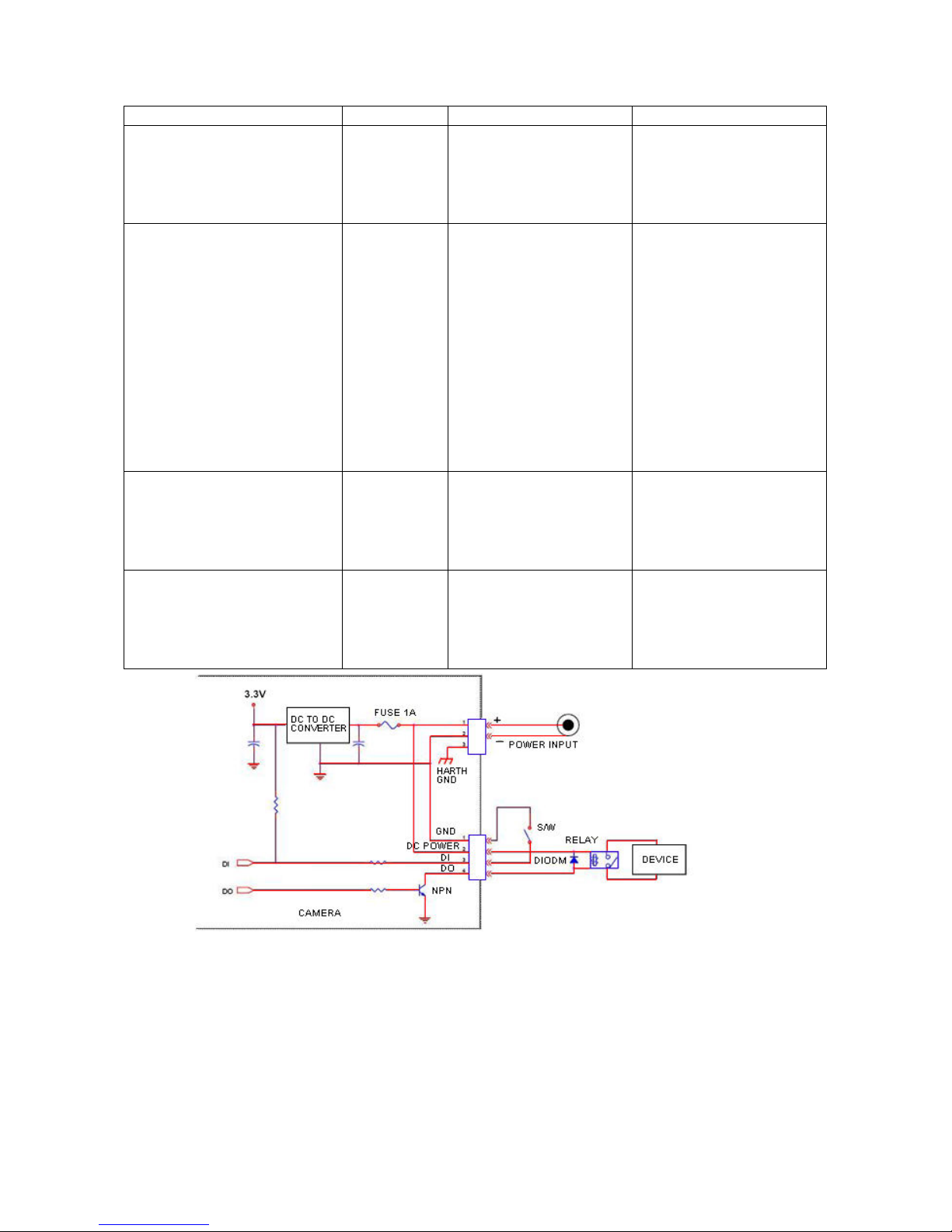
8. I/O terminal Connector
The I/O terminal connector provides an RS-485 interface, one transistor
output, two digital inputs, and connection points for auxiliary DC power
and GND.
The I/O terminal connector provides the interface to:
1 transistor output - For connecting external devices such as relays
and LEDs. Devices can be activated by Output buttons on the Live
View page or by an Event. The output will show as active (in Event
Configuration > Port Status) if the alarm device is activated.
2 digital inputs - An alarm input for connecting devices that can
toggle between an open and closed circuit, for use with devices
such as PIRs, door/window contacts, glass break detectors, etc.
When a signal is received the state changes and the input becomes
active (shown under Event Configuration > Port Status).
Auxiliary power and GND
GND Pin 1 Ground Description
12V Auxiliary DC Power
(not to power this
camera)
Pin 2 Electrically
connected in
parallel with the
connector for the
power supply, this
pin provides an
auxiliary connector
for main power to
the unit. This pin
can also be used to
power auxiliary
equipment with a
maximum current of
100mA.
Voltage: 12V DC,
Max: 1.2W
DI1(Digital Input) Pin 3 Connect to GND to
activate, or leave
floating (or
unconnected) to
Must not be exposed
to voltages greater
than 30V DC
26
deactivate.
DI2 (Digital Input) Pin 4 Connect to GND to
activate, or leave
floating (or
unconnected) to
deactivate.
Must not be exposed
to voltages greater
than 30V DC
DO(Digital Output) Pin 5 Uses an open-
collector NPN
transistor with the
emitter connected
to the GND pin. If
used with an
external relay, a
diode must be
connected in
parallel with the
load, for protection
against voltage
transients.
Max load = <100mA
Max voltage = 24V DC
(to the transistor)
RS-485A Pin 6 Data transmission
connector for
control of external
devices. (ex.
Pan/Tilt scanners)
Tx
RS-485B Pin 7 Data transmission
connector for
control of external
devices. (ex.
Pan/Tilt scanners)
Tx

27
2.3. Installation
Installing the Dome Camera
Indoor
Base Plate
Outdoor
1. Use screw hole indicator sticker to mark the desired camera position on
the ceiling.
2. Make one cable entry hole and 3 or 4 screw holes on the ceiling with the
electrical drill.
3. (Indoor) Remove the base plate from the bottom of the camera assembly.
(Outdoor) Use the provided L-type hex wrench to unscrew the cover of
the camera.
4. (Indoor) Align the base plate with the sticker and turn it clockwise to
secure it on top of the sticker.
28
(Outdoor) Align the housing with the sticker and fasten the screws to
secure the housing on top of the sticker.
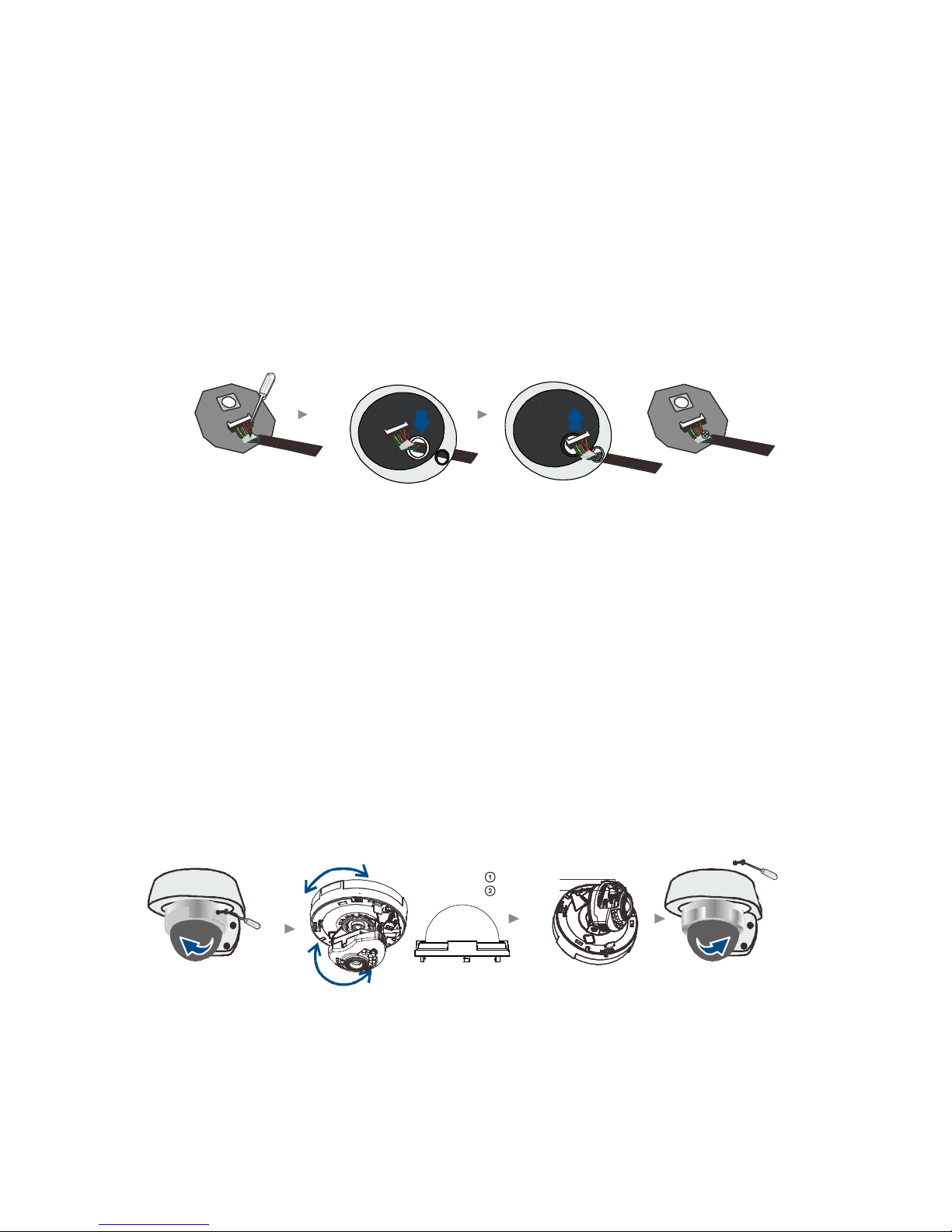
5. Thread the multiple connector interface cable through the cable entry
hole on the base plate or housing.
(Outdoor - Optional) The default cable entry hole is located on bottom of
the camera. If the installation requires use of the lateral-side cable hole,
remove the cap from the lateral-side cable hole. Disconnect the cable from
the board entirely, and reinsert it through the lateral cable hole.
Reconnect the cable to the camera.
Unscrew the retaining clip
Reattach the Retaining Clip
6. Connect the camera to network with the network connector.
7. Connect the power connector to a power outlet.
8. The status LED indicator will blink amber to indicate the boot-up sequence
has started. Wait until the LED is in a steady green state, indicating the
camera boot-up is complete.
9. (Indoor) Reattach the camera assembly to the base plate.
10. (Indoor) Remove the camera cover by twisting it counterclockwise.
Adjust the desired view angle as needed. On models equipped with
varifocal lenses, you may also adjust the zoom and focus by unscrewing
the corresponding puller, adjusting and then re-tightening the puller.
After adjustments are complete, reinstall the camera cover and secure it
with the included retaining screw.
Focus Puller
Zoom Puller
*
Vari foc al len s
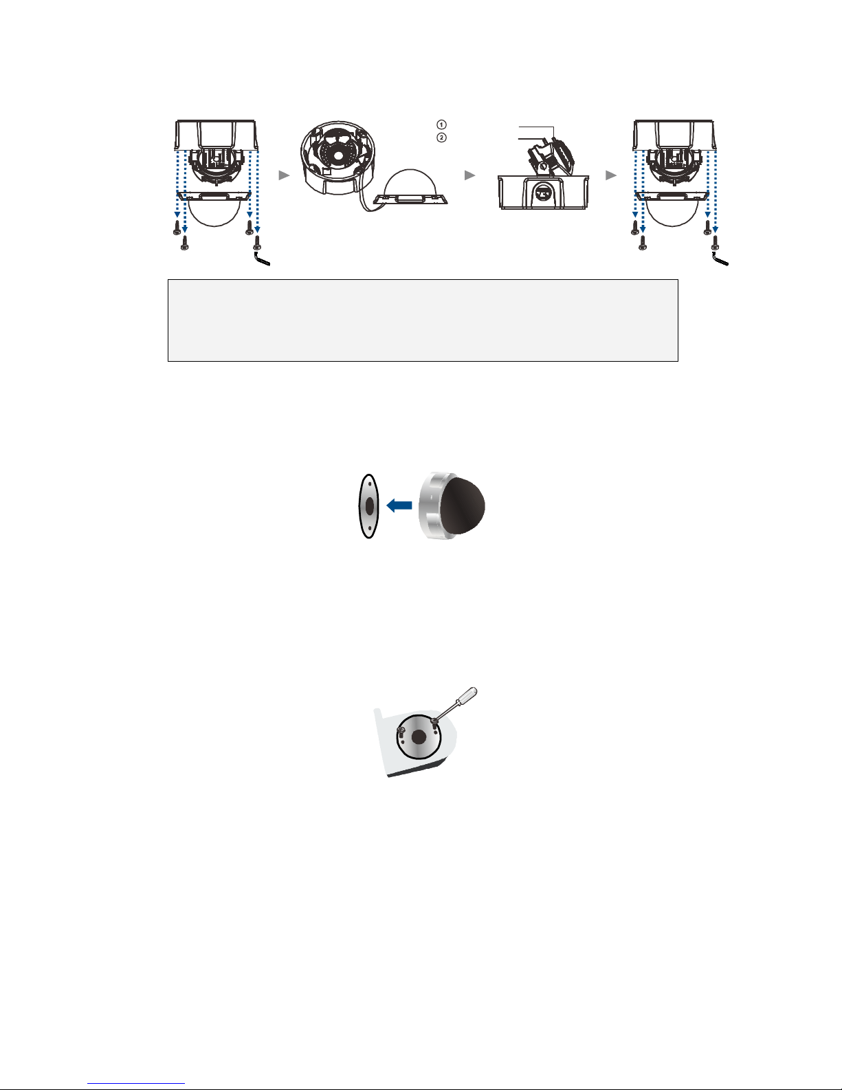
Outdoor) Unscrew the zoom puller on the lens and adjust the desired view
angle as needed. Re-tighten the zoom puller. Unscrew the focus puller on the
lens and adjust the focus as required. Re-tighten the focus puller and
29
reinstall the camera cover.
Focus Puller
Zoom Puller
Unscrew the Housing
Reattach the Housing
Note: (1) Cover removal is not required on models with motorized lenses
(CAM4360/4365/4371). (2) Please check the live view after the
camera is logged in.
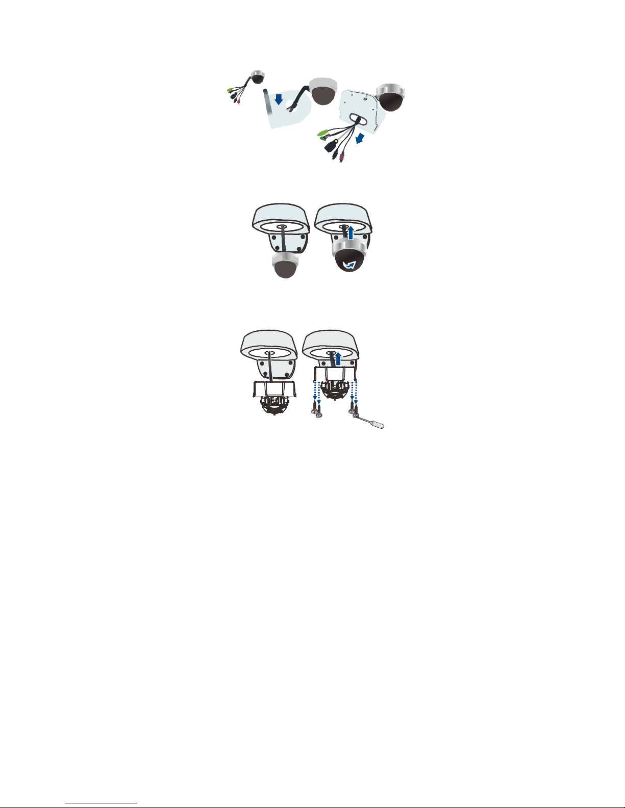
Installing the Dome Camera with the Mounting
Bracket (Optional)
1. (Indoor) Remove the base plate from the bottom of the camera.
(Outdoor) Use the provided L-type hex wrench to unscrew the cover of the
camera.
2. (Indoor) Align the base plate with the mounting bracket and fasten
screws to secure the plate on the bracket.
3. Fasten the mounting bracket to the wall at the desired camera location.
If required, use the provided thread-spaces on the side of the bracket for
wires.
4. (Indoor) Thread the multiple connector interface cable and any other
input or output cables for sensors or alarms through the base plate hole and
the back of the mounting bracket.
30
5. (Indoor) Reattach the camera assembly to the base plate.
(Outdoor) Align the housing with the mounting bracket and fasten screws
to secure the housing on the bracket.
 Loading...