

SurroundVideo AV5585PM, AV12585PM, AV12586PM, AV20585PM Installation Manual
SurroundVideo®!G5
Installation Manual!
Models:
5 Megapixel
• AV5585PM
12 Megapixel
• AV12585PM
• AV12586PM
20 Megapixel
• AV20585PM
!

!! ! Installation!Manual!
Page | 2 support@arecontvision.com
!
!
+1.818.937.0700 877.CAMERA.8 www.arecontvision.com avsales@arecontvision.com
SurroundVideo®!G5
!
Contents
!
Package Contents!..................................................................................................................................................!3!
In-ceiling Mount!......................................................................................................................................................!9!
Mounting Recommendations!..............................................................................................................................!14!
Pendant Mount!.....................................................................................................................................................!16!
Surface Mount!......................................................................................................................................................!17!
Wall Mount!............................................................................................................................................................!19!
Pole Mount!............................................................................................................................................................!20!
Corner Mount!........................................................................................................................................................!22!
Electrical Box Adapter!.........................................................................................................................................!24!
Adjusting the Pan, Tilt and Focus!......................................................................................................................!25!
Optional: Connecting Digital I/O!.........................................................................................................................!27!
Connecting Heater and Blower!..........................................................................................................................!29!
Camera Discovery, Setup, and Configuration!.................................................................................................!32!
Network Protocols!................................................................................................................................................!32!
General Remote Focus!.......................................................................................................................................!33!
AV IP Utility Focus Tab ........................................................................................................................... 34
Support!..................................................................................................................................................................!35!
!
!
!! ! Installation!Manual!
Page | 3 support@arecontvision.com
!
!
+1.818.937.0700 877.CAMERA.8 www.arecontvision.com avsales@arecontvision.com
SurroundVideo®!G5
'
CAUTION!
1. Do not attempt to service a damaged unit yourself. Refer all servicing to qualified service
personnel.
2. Wiring methods shall be in accordance with the National Electrical Code/NFPA 70/ANSI, and
with all local codes and authorities having jurisdiction. Wiring should be UL Listed and/or
Recognized wire suitable for the application.
3. Always use hardware e.g. screws, anchors, bolts, locking nuts etc. which are compatible with
mounting surface and of sufficient length and construction to insure a secure mount.
Package Contents
This equipment should be unpacked and handled with care. The original packaging is the safest
container in which to transport the unit and can be used if returning the unit for service. The packaging
contains:
• One (1) Arecont Vision SurroundVideo® G5 Camera
• One (1) mounting template
• Four (4) Mounting Wood Screws
• Four (4) Mounting Dry Wall Anchors
• One (1) RJ45 Female to female coupler
• One (1) Security L-key
• One (1) Hex key
!
!
!
!
!! ! Installation!Manual!
Page | 4 support@arecontvision.com
!
!
+1.818.937.0700 877.CAMERA.8 www.arecontvision.com avsales@arecontvision.com
SurroundVideo®!G5
Warranty Information
Global (3 Year) Limited Warranty
ARECONT VISION warrants to Purchaser (and only Purchaser) (the “Limited Warranty”), that: (a) each
Product shall be free from material defects in material and workmanship for a period of thirty-six (36)
months from the date of shipment (the “Warranty Period”); (b) during the Warranty Period, the
Products will materially conform with the specification in the applicable documentation; (c) all licensed
programs accompanying the Product (the “Licensed Programs”) will materially conform with applicable
specifications. Notwithstanding the preceding provisions, ARECONT VISION shall have no obligation or
responsibility with respect to any Product that (i) has been modified or altered without ARECONT
VISION’s written authorization; (ii) has not been used in accordance with applicable documentation; (iii)
has been subjected to unusual stress, neglect, misuse, abuse, improper storage, testing or connection;
or unauthorized repair; or (iv) is no longer covered under the Warranty Period. ARECONT VISION
MAKE NO WARRANTIES OR CONDITIONS, EXPRESS, IMPLIED, STATUTORY OR OTHERWISE,
OTHER THAN THE EXPRESS LIMITED WARRANTIES MADE BY ARECONT VISION ABOVE, AND
ARECONT VISION HEREBY SPECIFICALLY DISCLAIMS ALL OTHER EXPRESS, STATUTORY AND
IMPLIED WARRANTIES AND CONDITIONS, INCLUDING THE IMPLIED WARRANTIES OF
MERCHANTABILITY, FITNESS FOR A PARTICULAR PURPOSE, NON-INFRINGEMENT AND THE
IMPLIED CONDITION OF SATISFACTORY QUALITY. ALL LICENSED PROGRAMS ARE LICENSED
ON AN “AS IS” BASIS WITHOUT WARRANTY. ARECONT VISION DOES NOT WARRANT THAT (I)
THE OPERATION OF THE PRODUCTS OR PARTS WILL BE UNINTERRUPTED OR ERROR FREE;
(II) THE PRODUCTS OR PARTS AND DOCUMENTATION WILL MEET THE END USERS’
REQUIREMENTS; (III) THE PRODUCTS OR PARTS WILL OPERATE IN COMBINATIONS AND
CONFIGURATIONS SELECTED BY THE END USER; OTHER THAN COMBINATIONS AND
CONFIGURATIONS WITH PARTS OR OTHER PRODUCTS AUTHORIZED BY ARECONT VISION
OR (IV) THAT ALL LICENSED PROGRAM ERRORS WILL BE CORRECTED.
For RMA and Advance Replacement information visit http://www.arecontvision.com
!

!! ! Installation!Manual!
Page | 5 support@arecontvision.com
!
!
+1.818.937.0700 877.CAMERA.8 www.arecontvision.com avsales@arecontvision.com
SurroundVideo®!G5
Camera Overview!
The SurroundVideo® G5 multi-sensor, multi-megapixel dome camera pushes the boundaries of next
generation technology, providing users with four (4) integrated, motorized P-iris lenses for an incredible
180° panoramic experience in a single indoor/outdoor housing. SurroundVideo® G5 cameras provide
an all-in-one solution for capturing wide area video surveillance while maximizing the field-of-view and
reducing the total number of cameras required.
The SurroundVideo® G5 multi-megapixel camera series delivers 5-, 12-, or 20-megapixel resolutions.
For added flexibility, users can view the camera’s four (4) sensors individually or as a smooth transition
of all images blended together for a full 180° panoramic view. The camera is factory aligned with a
slight image overlap to ensure you never miss a thing.
The series combines a day/night mechanical IR cut filter for the highest image quality at any time of
day. The SurroundVideo® G5 camera features four (4) factory-installed P-iris lenses, ensuring the best
possible depth of field and image clarity for precise performance from each individual sensor. Once
mounted, the operator can quickly focus and position the camera remotely, eliminating the need to
adjust the camera on-site. No more hassle individually installing multiple cameras to cover a wide area,
manually focusing lenses, or risk missing critical information.
SurroundVideo® G5 is designed for demanding environments. Subjected and certified to rigorous dust
and water tests, the IP66 rating, and its extended operating temperature range make it ideal for outdoor
applications. The IK-10 rated, rugged dome housing is perfect for deterring vandals since it can
withstand the equivalent of 55 kg (120 lbs) of force.
!! ! Installation!Manual!
Page | 6 support@arecontvision.com
!
!
+1.818.937.0700 877.CAMERA.8 www.arecontvision.com avsales@arecontvision.com
SurroundVideo®!G5
Installation
1. Determine a secure location to mount the camera.
2. Use the supplied security L-key, to loosen the four (4) screws securing the dome cover (Figure
1). Remove dome cover. Do not remove screws from the dome cover.
Figure 1: Remove dome cover
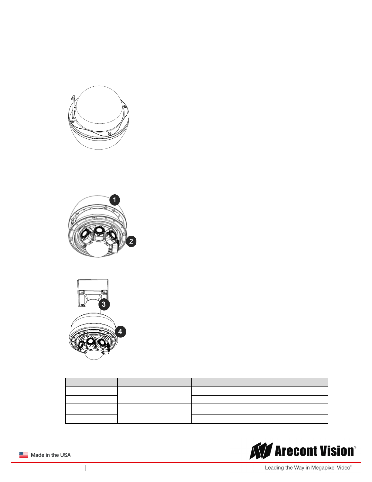
3. The SurroundVideo® G5 camera has been designed to provide installers with flexible mounting
options such as ceilings, walls, poles or corners. Choose the best method for your installation:
Remove for in-ceiling installation
!
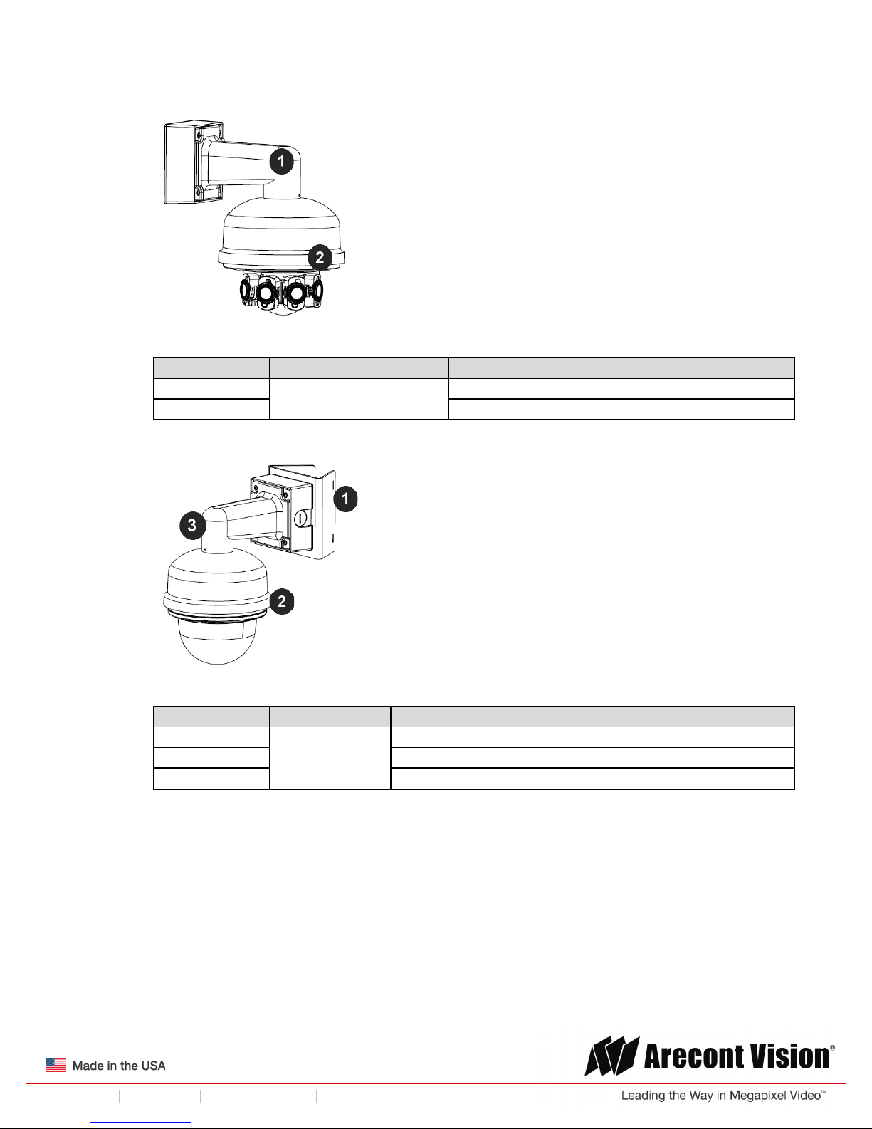
Pendant mount
Reference #
Mount Type
Parts Required
1
In-ceiling mount
Remove surface mount portion of camera
2
+ SV-FMA flush mount adapter
3
Pendant mount
AV-PMJB pendant mount
4
+ SV-CAP mount cap
!! ! Installation!Manual!
Page | 7 support@arecontvision.com
!
!
+1.818.937.0700 877.CAMERA.8 www.arecontvision.com avsales@arecontvision.com
SurroundVideo®!G5
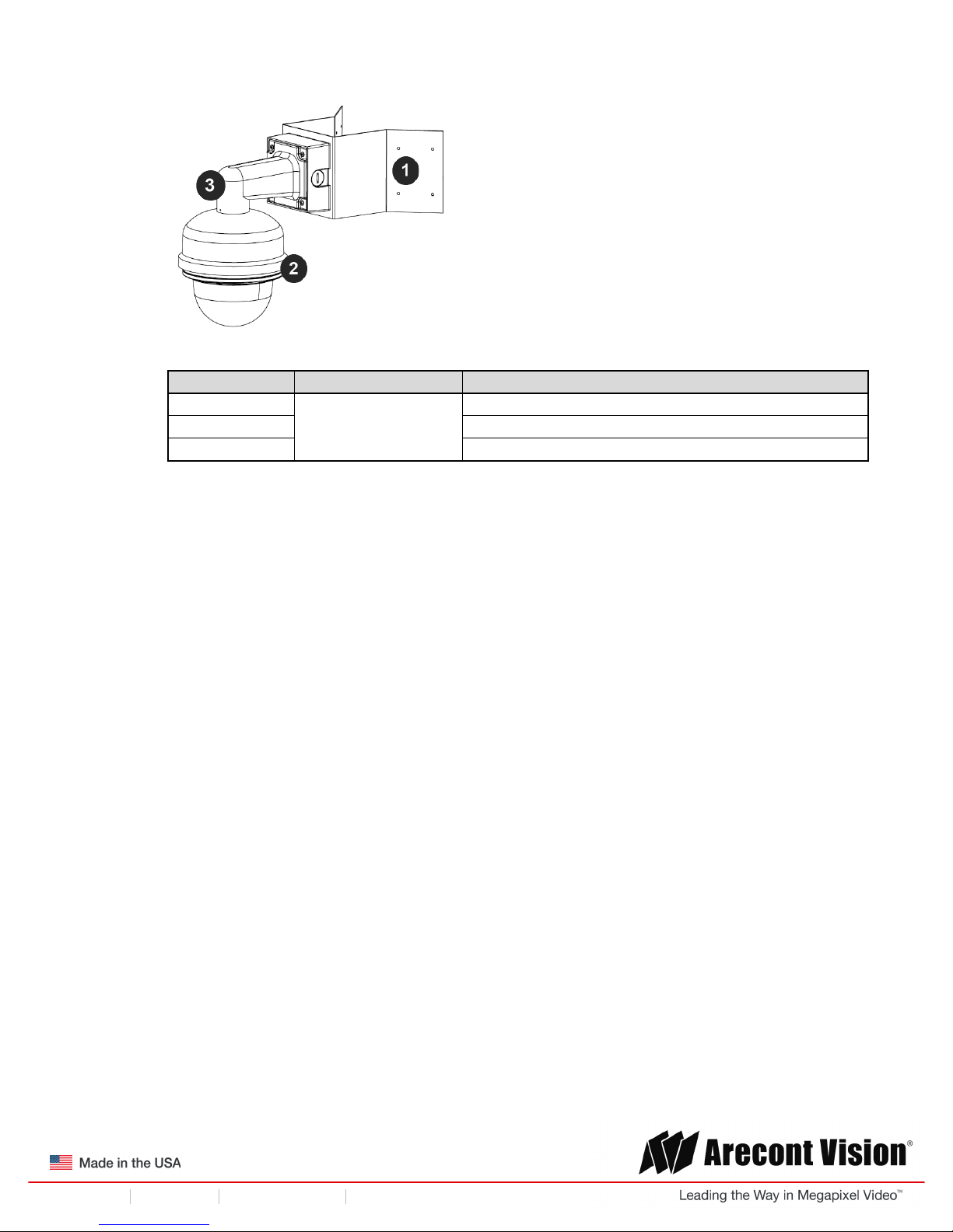
Wall mount
Reference #
Mount Type
Parts Required
1
Wall mount
AV-WMJB
2
+ SV-CAP mount cap
Pole mount
Reference #
Mount Type
Parts Required
1
Pole mount
AV-PMA
2
+ SV-CAP mount cap
3
+ AV-WMJB
!! ! Installation!Manual!
Page | 8 support@arecontvision.com
!
!
+1.818.937.0700 877.CAMERA.8 www.arecontvision.com avsales@arecontvision.com
SurroundVideo®!G5
Corner mount
Reference #
Mount Type
Parts Required
1
Corner mount
AV-CRMA
2
+ SV-CAP mount cap
3
+ AV-WMJB
NOTE: It is recommended to conduct periodic inspections of the installation. Rust on the metal
parts or screws may result in damage to the camera.
4. Use the Arecont Vision software AV IP Utility located on the CD or available for download at our
website (www.arecontvision.com) for camera discovery and setup (see Instruction Manual
located on the CD or available on our website).
!! ! Installation!Manual!
Page | 9 support@arecontvision.com
!
!
+1.818.937.0700 877.CAMERA.8 www.arecontvision.com avsales@arecontvision.com
SurroundVideo®!G5
In-ceiling Mount
To properly flush mount the SurroundVideo® G5 to a drop ceiling or similar surface, a flush mount
adapter kit (SV-FMA) is required (sold separately). An in-ceiling mount should only be attached onto
hard ceilings including wood, plastic, metal and concrete.
1. Cut a hole in the ceiling using the template provided to fit the camera housing.
NOTE: SurroundVideo® G5 ships with both surface mount and in-ceiling mount, the mounting
template takes both into consideration.
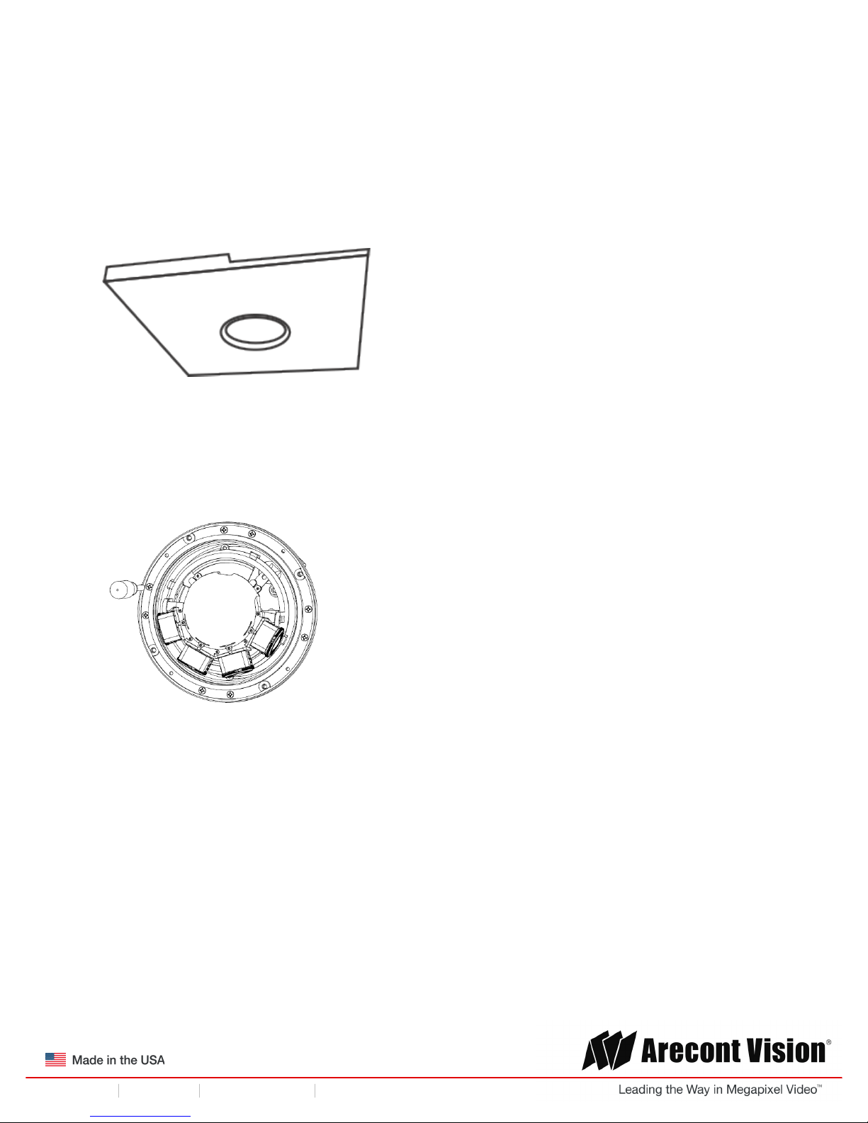
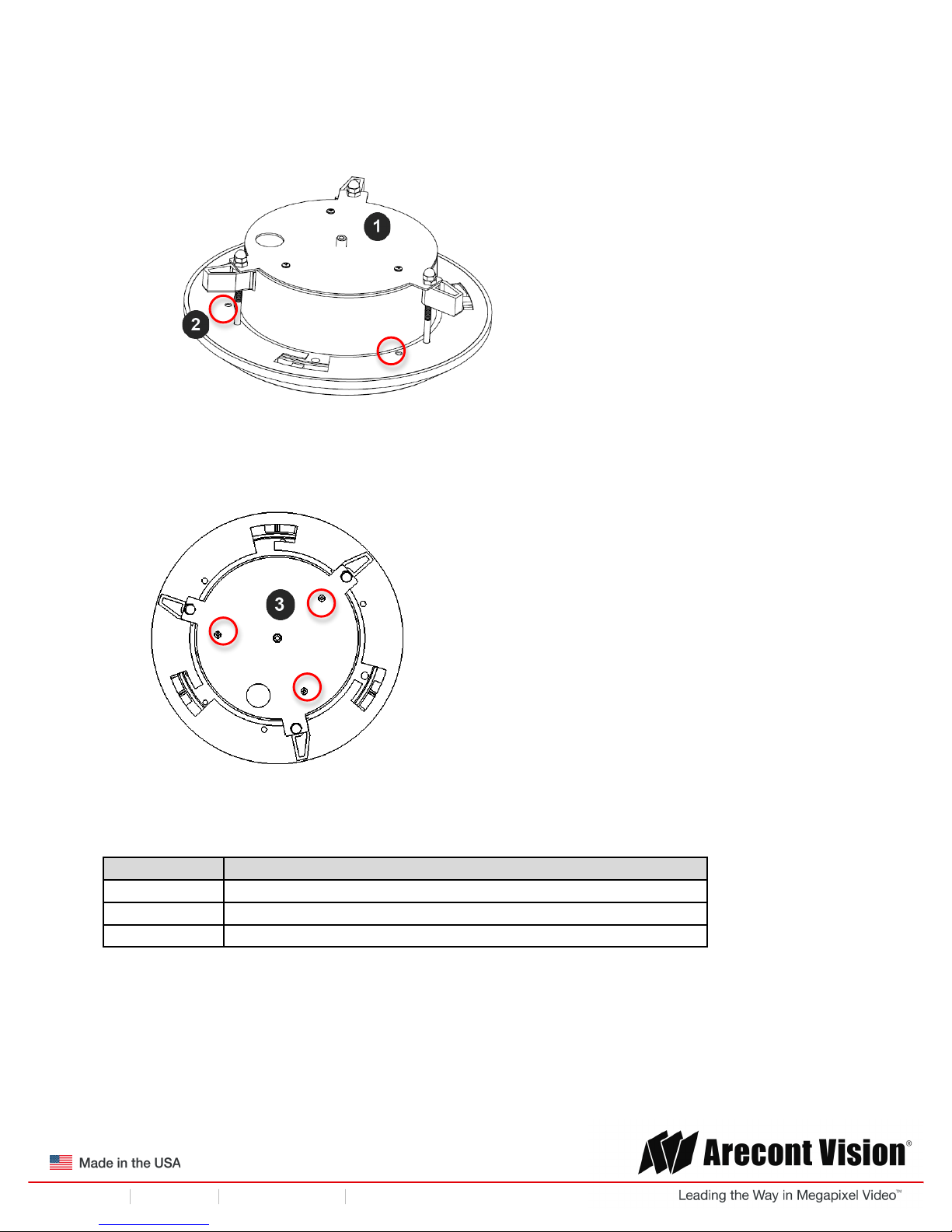
2. Loosen the four (4) machine screws with user-supplied #2 Phillips head screwdriver and remove
the in-ceiling mount housing from the surface mount housing (see Figure 4). Set surface mount
housing aside for future use.
Figure 3: Remove four (4) screws
NOTE: The above removed screws are also used to attach the camera with in-ceiling mount
housing to the pendant mount and wall mount. Do not discard.
!! ! Installation!Manual!
Page | 10 support@arecontvision.com
!
!
+1.818.937.0700 877.CAMERA.8 www.arecontvision.com avsales@arecontvision.com
SurroundVideo®!G5
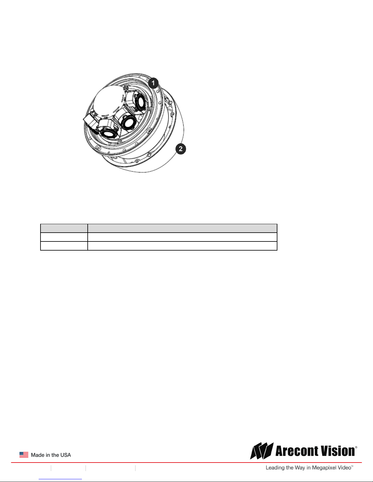
Figure 4: Remove in-ceiling mount from surface mount housing
Reference #
Description
1
In-ceiling mount
2
Surface mount
!! ! Installation!Manual!
Page | 11 support@arecontvision.com
!
!
+1.818.937.0700 877.CAMERA.8 www.arecontvision.com avsales@arecontvision.com
SurroundVideo®!G5
3. Attach the Flange Plate to the in-ceiling mount with the 3 set screws as shown in Figure 5.
Figure 5: Attach Flange Plate to in-ceiling mount with 3 set screws
4. Attach Top Plate to in-ceiling mount with other 3 set screws as shown in Figure 6.
Figure 6: Attach Top Plate to in-ceiling mount with 3 set screws
Reference #
Description
1
In-ceiling mount
2
Flange Plate
3
Top Plate
 Loading...