

Page 1
www.surna.com
303.993.5271
Surna Commercial Chiller
Operating & Maintenance Manual
Models: 24-1, 42-1, 60-1, 90-3, 120-3 Revised: February 2015
Page 2

Page 3

Table of Contents
Warranty Information 4
Limited Warranty 4
Limitation of Liability 4
Warranty Disclaimer 4
Product Suitability 4
Service Under Warranty 5
Service NOT Under Warranty 5
Warnings 6
Safety Symbols 6
Surna Chiller Safety Guide 6
Parts List 8
Installation Instructions 9
Location 9
Electrical 9
Plumbing 9
Plumbing Tips 10
Operations Instructions 12
Temperature Settings 12
System Maintenance Instructions 12
and Recommendations
System Specications 14
Troubleshooting 18
Temperature Controller has no 18
Power
Temperature controller is on, but 18
the Chiller Won’t Start
Fan Turns on and off, Even Though 19
the Compressor is Running
3
Page 4

Warranty Information
Limitation of Liability
Thank you for choosing the Surna Chiller System.
Because your chiller is built with
leading technologies and the highest quality
components, with proper care and
maintenance, it will provide you with years of
worry-free service. Please examine the unit upon
arrival to be sure there is no damage as a result
of shipping. If shipping damage has occurred,
please note the damage on the receiving slip,
and contact Surna immediately.
If you are missing parts or believe that you have
a warranty issue, DO NOT return this item to the
store of purchase. You must contact Surna at
303-993-5271 for troubleshooting and service
instructions.
Limited Warranty
A 90-day all-inclusive warranty for: parts, labor,
and shipping (including refrigerant). Choice of
repair facility and technician is at the discretion
of Surna.
A 1-year warranty on any defective part is also
provided (including refrigerant). Choice of repair
facility and technician is at the discretion of the
chiller’s owner, although Surna is happy to assist
with locating a technician. If Surna chooses the
technician, limited labor coverage may apply.
A 5-year warranty is provided for standard
compressors (excluding refrigerant and labor).
Choice of repair facility and technician is at the
discretion of the chiller’s owner, although Surna is
happy to assist with locating a technician.
To the extent allowable under applicable law,
Surna’s liability for consequential and incidental
damages is expressly disclaimed. Surna’s liability
in all events is limited to and shall not exceed the
cost of repair. Shipping damage is not covered
under warranty. In the event that the item(s)
arrive with shipping damage, Surna will assist with
the repair or replacement of the damaged item
ONLY if the damage is noted on the delivery
receipt.
Warranty Disclaimer
Surna provides product information in this
literature for the sole purpose of identication,
and does not state or imply that the products are
merchantable, or t for a particular purpose, or
that the products will conform to the descriptions.
Product Suitability
Many jurisdictions have codes and regulations
governing sales, construction, installation, and/
or use of products for certain purposes, which
may vary from those in neighboring areas. While
Surna attempts to ensure that its products
comply with such codes, it cannot guarantee
compliance, and cannot be responsible for how
the product is installed or used. Before purchase
and use of a product, review the product
applications, and all applicable national and
local codes and be sure that the product,
installation and use will comply with them.
A 10-year warranty is provided for high efciency
compressors (excluding refrigerant and labor).
Choice of repair facility and technician is at the
discretion of the chiller’s owner, although Surna is
happy to assist with locating a technician.
Note: Extended warranty for parts, labor and
shipping are available for purchase for a nominal
fee. Contact Surna within 15 days of your chiller’s
arrival if you would like to purchase an extended
warranty.
4
Page 5

Service Under Warranty
This product is warranted by Surna against
defects due to fault in workmanship or materials.
If the product has been damaged under
normal use, it will be entitled to warranty service
of the type described and within the timeframes
outlined. Damage caused by abnormal use, or
after the timeframes outlined have expired, carry
no such guarantee. Service under warranty is
provided only upon presentation of reasonable
evidence (purchase receipt) that the date of
claim is within the warranty period.
Service NOT
Under Warranty
The warranty is not valid if the defect is due to
accidental damage, misuse, shipping damage,
neglect, or in the case of alterations or repair
carried out by unauthorized persons. Surna can,
at its discretion, assist the consumer with shipping
claims in the case of damage incurred during
shipping, so long as the customer follows the
instructions outlined above.
5
Page 6
Warnings
Safety Symbols Used
CAUTION: Important information, consult
product manual and read the provided
instructions carefully.
WARNING: Potential electric shock hazard.
Protective Earth Connection
Action Prohibited
Surna Chiller Safety Guide
Please read the information in this document
carefully prior to attempting the installation,
operation and/or servicing of the Surna Chiller.
This document contains all information required
to install and operate the Surna Chiller
commercial line of water-cooling devices.
Failure to follow the directions provided
herein may impair the safeties provided and
could cause damage to the Surna Chiller
equipment and or accessory equipment,
damage to building facilities, and/or cause
serious injury or death to the operator. Please
adhere to all applicable safety guideline
requirements in this document and all applicable
electrical and mechanical jurisdictional codes.
Prior to providing power to the equipment, be
sure to inspect the area for water spills, which
may present a shock hazard to the user. Take
extra care to mount accessory electrical
equipment away from areas regularly exposed
to water and be sure to provide secure wire and
cable routing to protect personnel from shock
hazards.
Only operate the equipment with an
appropriately sized breaker in place and wire
sizes with adequate current carrying capacity.
Consult with an electrician before attempting
electrical installation.
Using the Surna Chiller equipment in a manner
not described in this manual may void its
warranty.
Following unit installation and maintenance
activities, the user shall observe the system
operation to verify that normal operation has
resumed prior to leaving the equipment to
operate unattended.
6
Page 7
Only use parts provided with, or specied for use
with, the Surna Chiller equipment.
DO NOT operate the Surna Chiller at a
temperature setting lower than 45°F (7°C) or risk
freezing the evaporator, which is not covered
under the product warranty.
DO NOT operate the Surna Chiller without an
appropriate mixture of Propylene Glycol. For
optimum performance, Surna recommends using
a 50%/50% (glycol/water) mixture. The system
requires a minimum of 30%/70% (glycol/water)
mixture to operate safely. A 50%/50%
(glycol/water) mixture is needed when outdoor
temps fall below 20°F (-7°C).
DO NOT operate the Surna Chiller without
adequate water ow. These chiller systems
require 2.5 GPM (Gallons per Minute) per ton of
cooling to prevent freezing of the evaporator.
DO NOT remove the grounded connection
while power is being supplied to the Surna Chiller
equipment. Doing so presents an electric shock
hazard to users and service personnel.
Our chiller systems are approved for use with
devices used in water chilled applications that
allow for the use of propylene glycol and
require a temperature of 45°F (7°C) or higher.
Any such devices shall be used in accordance
with the safety regulations in your local
jurisdiction. Please contact Surna if you are
unsure about how to properly incorporate our
chillers within your system.
DO NOT use the Surna Chiller indoors without
proper ventilation. If the indoor temperatures
are greater than 100°F (38°C), the room does not
have adequate ventilation.
7
Page 8
Surna Chiller Parts List
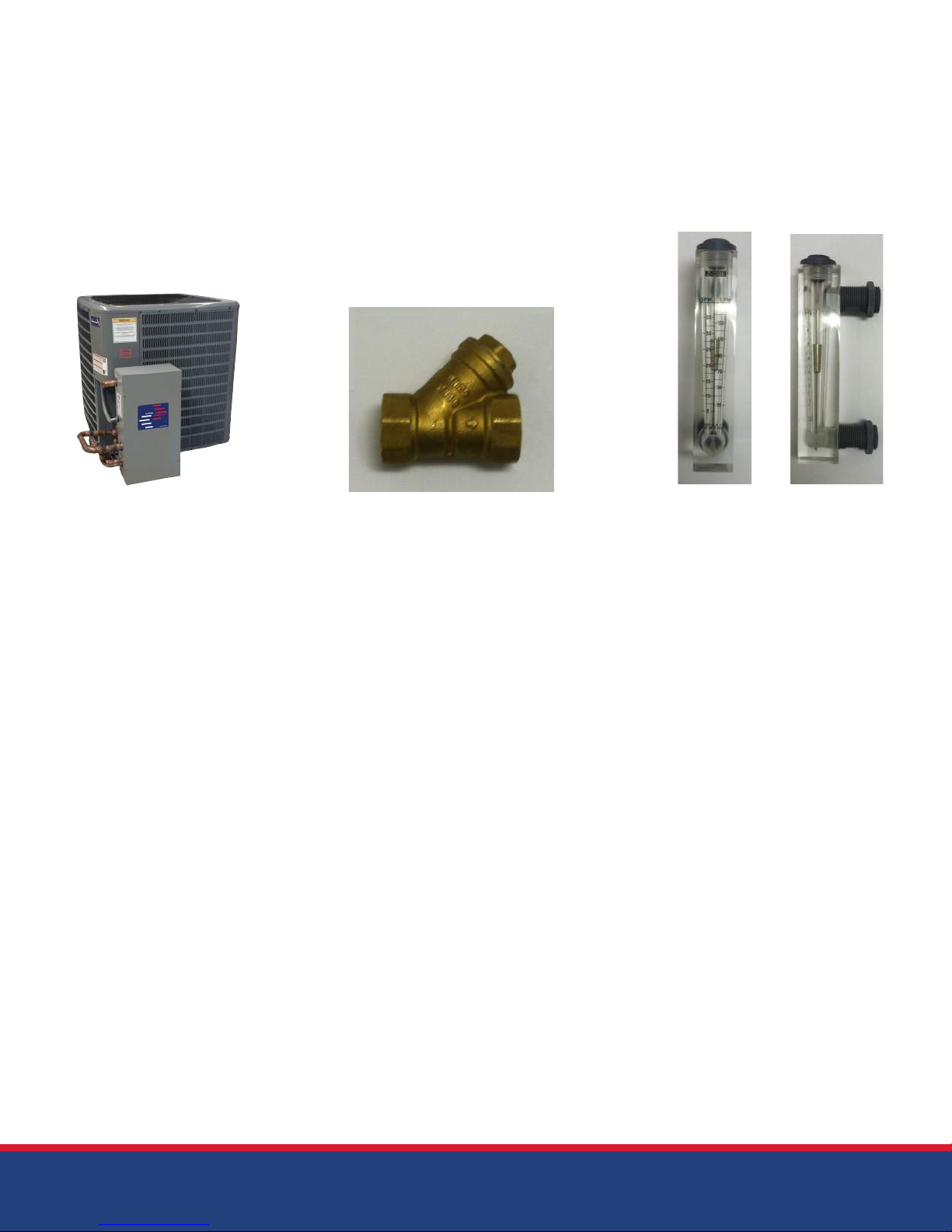
Below is a list of all parts provided with each
Surna Chiller system.
1. Surna Chiller Product Manual
2. Chiller Unit
3. Strainer
4. Flow Meter
3. Brass Strainer
4. Flow Meter (front and side view)2. Chiller Unit
8
Page 9

Installation Instructions
Location
Only install the Surna Chiller equipment on a at,
level surface. Acceptable surfaces include concrete slabs, A/C pads, or pressure treated wood.
Before attempting installation, be sure to verify
that the mounting surface exhibits suitable load
bearing capacity. Please consult the
specication section of this document for the
weight information for each chiller model. The
unit shall be placed on a hard surface that
extends a minimum of 6 inches from all sides of
the chiller housing. This is to prevent dirt and
debris from entering the condenser, which will
affect cooling efciency. DO NOT place the unit
directly on the ground. Damage caused by
debris striking the condenser is not covered
under warranty. Roof mounting is acceptable
so long as the roof joists are rated to support the
chillers weight load. Consult your local building
codes and guidelines before attempting roof
mounting.
Following installation, verify that there is a
minimum of 24 inches of clearance from
obstruction on all sides and no obstructions
above the unit to ensure proper airow over the
condenser.
Electrical
Contact an electrician if you are not familiar
with the local codes and standards in your
jurisdiction. Before attempting electrical
installation, be sure to verify that
appropriately sized circuit breakers are in
place to handle the electrical load of your
chiller. The ampacity is provided for each
chiller unit in the Specications section of this
document along with recommendations for
sizing your circuit breaker. The cross-sectional
wire sizing to be used for the power
connections is a product of the chiller unit’s
ampacity and the length of wire needed.
Consult an electrician for more information
on power wire sizing and connection.
Plumbing
IMPORTANT: You must use a mixture of Propylene
Glycol and water in your reservoir. Your
reservoir should contain 30% Propylene Glycol
to 70% water (minimum), and contain up to 50%
Propylene Glycol to 50% water (maximum). We
recommend a 50%/50% mixture for optimum
cooling efciency. A 50%/50% mixture is
necessary when outdoor temperatures fall below
20°F (-7°C). Failure to use an appropriate amount
of Propylene Glycol may result in degradation
of system performance and/or damage to the
chiller unit which is not covered under warranty.
DO NOT use standard car antifreeze in the Surna
Chiller System (Ethylene Glycol).
Reservoir size is dependent on the type and
amount of equipment being cooled. If your
chiller is properly sized, a reservoir size of greater
than 50 gallons per 10 Tons of cooling is rarely
necessary, although larger reservoirs will result in
longer cycle times.
Depending on the size of your unit, the
plumbing connections will come in either 1” or
3/4” connections. Refer to the Specications
section in this document for information on your
chiller’s plumbing inlet/outlet connections. It is
our recommendation that you use tubing that
is sized 1/4” larger than the provided plumbing
connections on your specic chiller unit (use
an appropriate adapter for connection to the
chiller). This is to ensure maximum water ow
without restriction.
Be sure to install the water connections to the
appropriately labeled “WATER IN” and “WATER
OUT” ports on the chiller unit. This equipment will
not function if these connections are reversed.
9
Page 10
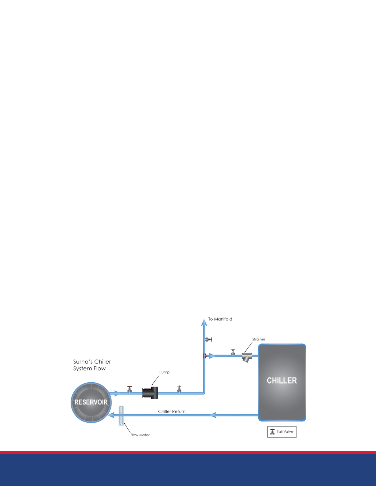
Important Plumbing Tips
• ALWAYS use a backup wrench when
installing water ttings. Failure to do so can
cause damage to the copper lines, which is
not covered under warranty.
• ALWAYS use the brass strainer that is
provided with the unit. This strainer should be
installed on the supply line water connection
and is meant to prevent particles from
entering the heat exchanger so as to
maintain optimum water ow and efciency.
• Periodically check the strainer to verify that
the chiller is receiving the desired water ow.
We recommend installing in-line water valves
both before and after the strainer. This will
allow you to inspect the strainer regularly
without losing Glycol.
• If 90 degree bends are required in your
layout, we recommend using long-turn 90’s
or exible spa tubing to prevent restriction of
water ow. Spa tubing can be glued with
PVC glue or PVC tting. In either case, we
recommend using piping/tubing that is sized
1 size larger that the chiller water connections
provided.
• Your chiller requires a ow rate of 2.5 GPM/
ton (i.e. 5 GPM for a 2 ton chiller, 25 GPM for
a 10 ton chiller, etc.). Failure to ensure
adequate water ow through the chiller may
result in system degradation, damage to the
evaporator, and/or damage to the
compressor.
• The chiller is provided with an appropriate
ow meter for your system so that you can
verify adequate ow through the chiller.
Always install this meter INDOORS where it
can be easily monitored. Maintaining proper
ow rates through your chiller is critical to the
efciency of the unit and to prevent
damaging the evaporator.
• The proper pump sizing will vary based
on water line lengths, equipment being
pumped to, lift rates, etc. Please contact
Surna for more details on properly sizing your
pump.
Flow Diagram
Single pump layout. Consult Surna if your layout requires multiple pumps or chillers.
10
Page 11
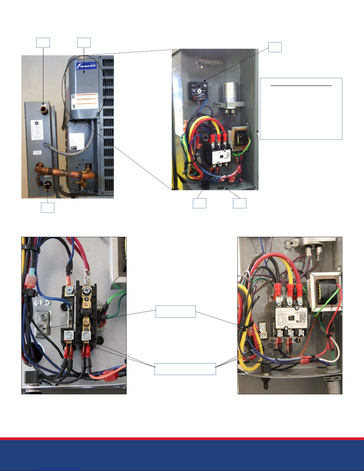
Installation Connections
A
B
C
D E
F
Installation Connections
A – Water Inlet
B – Water Outlet
C – Electrical Panel
D – Power Connections
(beneath contactor)
E – Cable Routing Port
F – Delay Timer
2, 3.5 & 5-Ton Power 7.5 & 10-Ton Power
Grounding
Power Connectors
NOTE: If the compressor makes an unusual noise after applying 3-Phase power (7.5 and 10-ton units), you have installed the
power wiring backwards. Shut the unit off immediately, shut the electric supply off at the breaker, and reverse any 2 of the
3 line conductor wires.
11
Page 12

Operation Instructions
Temperature Settings
After you have made all of the appropriate
electrical and plumbing connections per the
instructions provided above, you may power on
the chiller unit and set your desired temperature
using the following procedure:
• Turn the chiller on using the switch on the
temperature controller.
• Press “Set” once: Choose Celsius or
Fahrenheit using up or down arrows.
• Press “Set” twice: Using the up and down
arrows, set your desired chiller temperature set
point (NEVER set this below 45°F / 7°C)
• Press “Set” three times: This is your
temperature differential and should NEVER be
changed from the factory preset of 3 degrees.
Reducing this will cause rapid cycling of the
chiller’s compressor, which will shorten the
life-span of the unit. Increasing this number
could lead to temperature spikes.
• Press “Set” four times: This should always
read “C1” per the factory preset. If this menu
reads anything other than “C1,” the chiller will
not function.
• All other settings should never be changed
from the factory presets.
System Maintenance
Instructions and
Recommendations
• ALWAYS maintain a clean condensing coil
for maximum efciency. Chiller units located
indoors will need to be cleaned often due
to dust build-up. Units located outdoors are
often washed by rainfall.
• ALWAYS maintain 24” of clearance on all
sides of the unit and an unobstructed
clearance on the top of the unit. Make sure
the unit has plenty of fresh air available for
heat exchange. We recommend outdoor
use.
• DO NOT use the chiller indoors without
proper ventilation. If temperatures in the
room reach 100°F (38°C), the room is not
properly ventilated.
• If using the chiller in an environment with
freezing ambient temperatures, a compressor
heater is needed to prevent the compressor
from freezing. Damage caused due to failure
to use a compressor heater is not covered
under warranty. The compressor heater can
be installed at the factory, or be purchased
aftermarket and be installed on-site by a
qualied technician.
• When using the chiller unit with water-cooled
air handlers: Start the chiller temperature at
55°F (13°C) and adjust up or down based on
cooling and dehumidication needs. NEVER
set this temperature below 45°F (7°C).
• When using your chiller with other
water-cooled devices, such as Ice Boxes or
Cool Coils: Start the chiller temperature at 65°F
(18°C) and adjust up or down based on
cooling needs. NEVER set this temperature
below 45°F (7°C).
12
• ALWAYS provide a minimum of 2.5 GPM
(Gallons per Minute) per ton of chiller
capacity to prevent freezing of the
evaporator and to achieve optimum system
performance.
• ALWAYS install the strainer/lter provided
with the equipment to prevent debris from
clogging the heat exchanger.
• We strongly recommend a 50%/50% (glycol/
water) mixture to operate your chiller system
under optimum conditions. At a minimum, a
30%/70% (glycol/water) mixture must be used
for chiller operation. Not using the prescribed
Page 13

glycol/water mixture may cause system
inefciencies or damage to the evaporator,
which is not covered under warranty.
• NEVER set the chiller below 45°F (7°C) or risk
freezing the evaporator, which is not
covered under warranty.
• Only use properly sized breakers and wiring
with an appropriate ampacity or damage to
the compressor could occur. The further the
unit is away from the breaker box, the larger
the wire gauge must be to carry
sufcient amperage when the compressor
starts. Damage caused by improper wiring is
not covered under warranty. Please consult
with a qualied electrician for more
information on proper breaker and wire sizing
if you are not sure.
• Chillers must be installed on concrete or
an A/C condenser pad. Failure to do so can
cause the condenser to become dirty sooner
from splashing dirt and debris when it rains.
This will also cause premature rusting of the
chiller base where it contacts the ground.
• Proper voltage must always be maintained.
Consult the System Specication section of
this document for more information.
13
Page 14
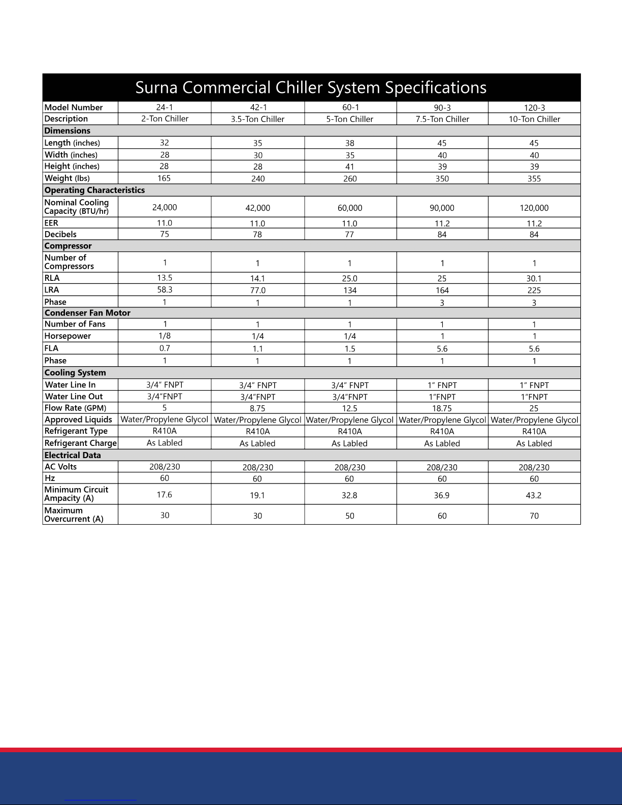
System Specications
14
Page 15
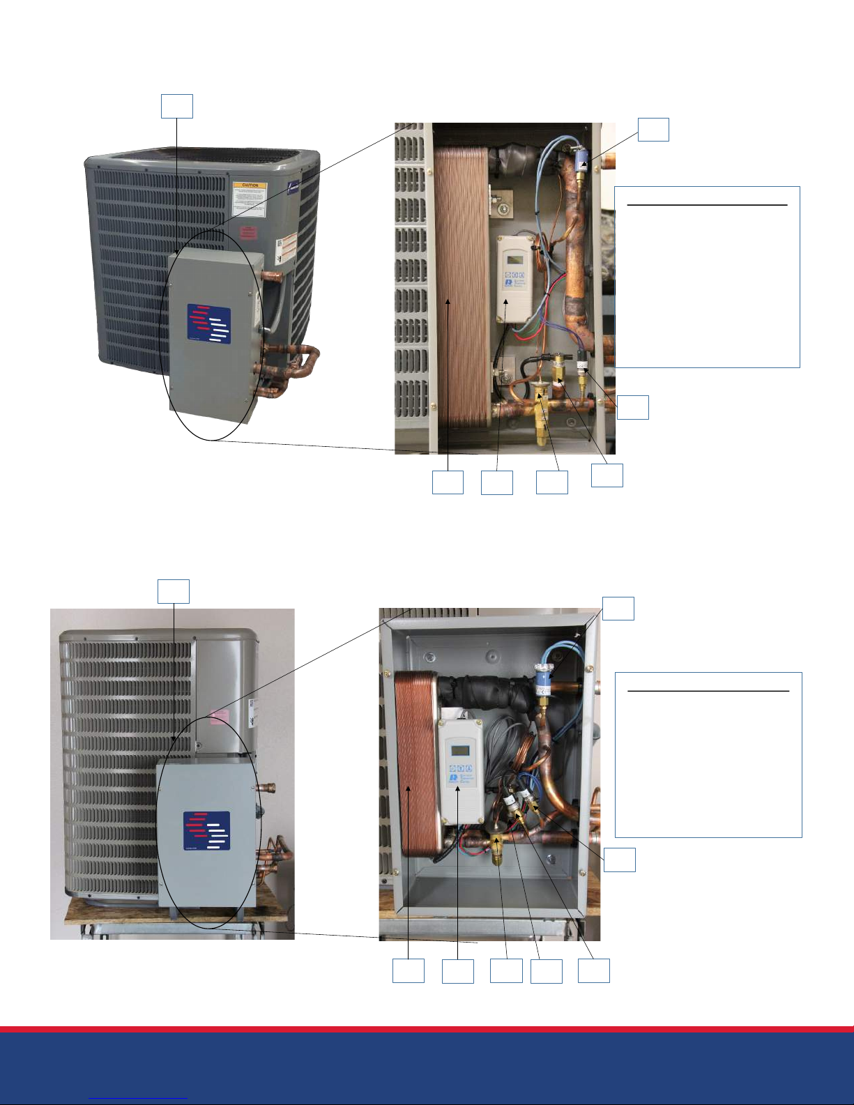
10-Ton Chiller Chiller Control Panel Connections
A
F
Control Panel Components
A – Control Panel Exterior
B – Heat Exchanger
C – Temperature Controller
D – Thermal Expansion Valve
E – Flow Switch
F – Low Pressure Switch
G – Fan Cycle Switch
*High Pressure Switch
located inside unit
G
B
C
D
5-Ton Chiller Control Panel Connections
A
E
F
Control Panel Components
A – Control Panel Exterior
B – Heat Exchanger
C – Temperature Controller
D – Thermal Expansion Valve
E – High Pressure Switch
F – Low Pressure Switch
G – Fan Cycle Switch
H- Flow Switch (behind E)
G
B
C
D
H
E
15
Page 16
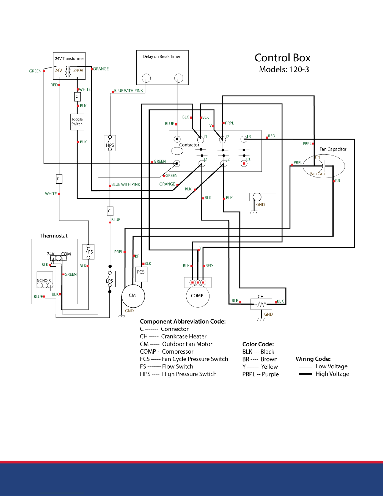
10-ton Chiller Wiring Diagram
16
Page 17
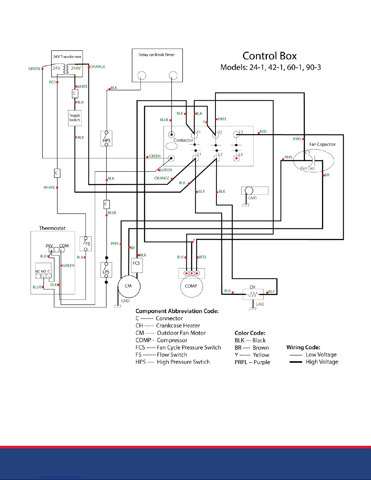
2-7.5 ton Chiller Wiring Diagram
Page 18

Troubleshooting
This unit is equipped with safety sensors that may
include high and low pressure sensors for the
refrigeration circuit and also a ow switch to help
prevent freezing if there is a pump failure or other
loss of ow. If any of these sensors are not
satised, they will not allow the chiller to function.
Some of the troubleshooting steps listed below
can be performed by the end user, and some
of these steps must be performed by a licensed
HVAC technician. Retain this guide should your
chiller ever require servicing in the future.
sure you are getting 24VAC across the sensor
while sufcient water is owing. If there is no
voltage across the sensor leads with a
proper ow-rate, then the sensor needs to be
replaced.
9. Check the direction of ow in the water circuit.
If water is owing backwards, the ow switch will
not allow power to the temperature controller,
and the unit will not function properly.
Temperature controller
is on, but the unit will not
start
Temperature controller has
no power
1. Check and make sure switch is in the on
position.
2. Check breaker for proper function.
3. Check ow meter for adequate water ow
(2.5 GPM per ton). Insufcient ow will cause
loss of power.
4. QUALIFIED SERVICE PERSONNEL ONLY: Check
ow for proper voltage at the unit with an
electric volt-meter.
5. Visually check for any loose wires.
6. QUALIFIED SERVICE PERSONNEL ONLY:
Remove the front cover of the temperature
sensor and check voltage. If 24 VAC is
present, and all wires are installed and tight,
then most likely the controller will need to be
replaced. If no voltage is present, see the next
step.
7. The controller is wired so that it will not come
on if there is not sufcient water ow to the unit.
If there is no voltage at the controller, check
the ow and verify that the chiller is receiving at
least 2.5 GPM for each ton of cooling required.
If there is sufcient ow, see the next step.
8. Check connections of the ow sensor (the
ow sensor is installed in the water line) to make
1. The unit has a 5-minute delay on start-up
before beginning normal operation. Before
troubleshooting, ensure that 5 minutes have
passed.
2. Check the temperature set-points of the
controller to verify that the desired settings are
still in place. The factory differential temperature
should be 3 degrees, and shouldn’t be changed.
For example, with the factory set differential
temperature setting of 3 degrees, and a desired
temperature setting of 45°F (8°C), the unit will not
start until the water reaches 48°F (9°C).
4. Check to make sure the controller is set to C1.
5. QUALIFIED SERVICE PERSONNEL ONLY: Check
voltage at relay (space terminals on each side),
which should be 24VAC while the temperature
controller is calling for cooling, then check for a
loose wire on the controller. If none are found,
check for power at the relay inside the controller.
If you have power there the other cause would
be a tripped high/low pressure sensor, in which
case an HVAC technician will need to service
your unit. He/she should check the refrigeration
pressures with a gauge set to verify that there is
not a problem with system pressures. If no
problems are found with pressure, then the high/
low pressure sensor may need to be replaced.
6. QUALIFIED SERVICE PERSONNEL ONLY: Check
the voltage across the ENDS of the main relay
with a meter. This should be 240VAC on each
side when the temperature controller is
18
Page 19

calling for cooling. If there is not 240VAC on
each side, the relay is malfunctioning and
needs to be replaced.
Fan turns on & off even
though the compressor is
7. QUALIFIED SERVICE PERSONNEL ONLY: If
there is voltage across the relay when the
temperature controller is calling for cooling
and the compressor, fan, or both are not
coming, the capacitor could be
malfunctioning and needs to be replaced.
Check voltage across the capacitor to
verify. Bulging capacitors are an indication of
a problem.
8. If both the compressor and fan are not
engaging, then the problem is almost certainly
an easily replaced bolt on component, and
not with the fan or compressor themselves. If
one of the two components is not running after
these troubleshooting steps have been
attempted, there could be a problem with
one of those components and they may need
to be replaced. The fan motor is simple to
replace and can be done by the end user
after all power has been disconnected from
the unit. If compressor replacement is
required, a licensed refrigeration technician
must complete the associated repairs.
running
1. The unit is equipped with a fan cycle switch,
in which case the fan will come on only when
absolutely needed. The cycling of the fan is
most common in cooler weather.
9. QUALIFIED SERVICE PERSONNEL ONLY: If the
refrigerant charge of the unit is in question, the
best avenue for checking this is to recover and
weigh the charge. The amount of refrigerant
in the system is written on the product label.
Pressures are an unreliable indicator of proper
charge.
19
Page 20

 Loading...