


BY EMB MFG INC.
EMB Manufacturing Inc.
4144 Boomer Line · St. Clements, On · N0B 2M0 · Canada
Ph: (519) 699-9283 · Fax: (519) 699-4146
www.surgemaster.ca
STANDARD PORTABLE
GENERATORS
OPERATOR'S MANUAL
SHS3000
SHS3000R
SCS3000
SCS3000R
SHS7000
SHS7000R
SCS7000
SCS7000R
SHS3000
SHS3000R
SHS5000
SHS5000R
SHS7000
SHS7000R
FIRST USE: DO NOT attempt to crank or start the engine
before it has been properly lled with the recommended amount and type of oil.
Damage to the generator as a result of failure to follow these instructions will void your
warranty. See the engine owners manual for detailed instructions.
SCS3000
SCS3000R
SCS5000
SCS5000R
SCS7000
SCS7000R
SHS5000
SHS5000R
SCS5000
SCS5000R
Thoroughly review this manual and the engine manual for
U1 Lawn & Garden 250 CCA battery is not included
Keep this manual with the Generator at all times
PRINTED IN CANADA
REV 080316 PART NUMBER: Z97094
safe and proper operation.
PS
C
ELECTRICAL SAFETY
®
CERTIFIED.

TABLE OF CONTENTS
WARRANTY ............................................................... 3
DELIVERY INSPECTION REPORT ........................... 4
SERIAL NUMBER LOCATION .................................. 5
LABEL INFORMATION ............................................. 5
1 INTRODUCTION ........................................... 6
2 SAFETY ........................................................ 7
2.1 SAFETY DO'S & DON'TS' ......................... 8
2.2 EQUIPMENT SAFETY GUIDELINES ........ 9
2.3 SAFETY TRAINING ................................. 10
2.4 PREPARATION ........................................ 10
2.5 MAINTENANCE SAFETY .........................11
2.6 BATTERY SAFETY ...................................11
2.7 REFUELING SAFETY ............................. 12
2.8 OPERATING SAFETY ............................. 12
2.9 TRANSPORT SAFETY ............................ 13
2.10 STORAGE SAFETY................................. 13
2.11 ELECTRICAL SAFETY ............................ 13
2.12 GAS MOTOR SAFETY ............................ 14
2.13 SIGN-OFF FORM .................................... 15
3 SAFETY SIGNS .......................................... 16
3.1 HOW TO INSTALL SAFETY SIGNS: ....... 16
3.2 SAFETY SIGN EXPLANATIONS: ............ 16
4 OPERATION & FEATURES ....................... 18
4.1 TO THE NEW OPERATOR OR OWNER 18
4.1.1 SAFE CONDITION ................................. 18
4.2 MACHINE COMPONENTS ...................... 19
4.3 MACHINE BREAK-IN .............................. 20
4.4 PREOPERATION CHECKLIST................ 20
4.5 CONTROLS ............................................. 21
4.5.1 ENGINE CONTROLS .............................. 21
4.5.2 ELECTRICAL PANEL FEATURES ........... 22
4.5.3 ELECTRICAL PANEL............................... 23
SHS3000 & SHS3000R ....................... 23
SCS3000 & SCS3000R ....................... 23
SHS5000 & SHS5000R ....................... 23
SCS5000 & SCS5000R ....................... 24
SHS7000 & SHS7000R ....................... 24
SCS7000 & SCS7000R ....................... 24
CIRCUIT BREAKERS:......................... 25
OPERATING HINTS: ........................... 25
4.6 ELECTRICAL LOAD ...........................26
4.6.1 WATTAGE AND LOAD .........................26
REACTIVE LOAD ............................26
RESISTIVE LOAD ...........................26
CONTINUOUS WATTAGE ..............26
MAXIMUM WATTAGE .....................26
4.6.2 CALCULATING LOAD .........................26
4.6.4 WATTAGE CHART ...............................27
5 FIELD OPERATION ................................28
5.1 PREPARE ............................................28
5.2 START ..................................................29
5.2.1 STARTING THE GENERATOR:...........29
5.2.2 STOPPING: .........................................29
5.2.3 EMERGENCY STOPPING: .................29
5.2.4 TERRAIN: ...........................................29
5.2.5 WEATHER: ..........................................29
5.2.6 ELECTRICAL LOADS: .........................29
5.2.7 COMPONENT CONDITION: ...............29
5.2.8 ELECTRICAL HAZARDS: ....................29
5.3 RESIDENTIAL......................................30
5.4.1 TRANSPORTING: ...............................30
5.4.2 LIFTING HOOK: ...................................31
5.4.3 FOLDING HANDLE: ............................31
5.5 STORAGE ...........................................32
5.5.1 PLACING IN STORAGE ......................32
5.5.2 REMOVING FROM STORAGE ...........32
6 SERVICE AND MAINTENANCE ............33
6.1 SERVICE .............................................33
6.1.1 FLUIDS AND LUBRICANTS ................33
6.2 MAINTENANCE ...................................34
6.2.1 GENERAL MAINTENANCE .................34
6.2.2 ENGINE MAINTENANCE ....................34
6.2.3 ALTERNATOR MAINTENANCE ..........34
6.2.4 BATTERY MAINTENANCE .................35
7 SPECIFICATIONS ..................................36
7.1 MECHANICAL......................................36
7.2 BOLT TORQUE ....................................37
8 TROUBLE SHOOTING ...........................38
9 ACCESSORIES ......................................39
10 INDEX .....................................................40
2

Warranty
of prots. The manufacturer is under no circumstances liable for tow vehicle of any kind. The manufacturer is not liable for
receipt of the product. Unit or parts shall be returned at the customer’s expense to the authorized service centre. Damage
WARRANTY
Effective on products retailed on or after January 1, 2015.
Register your product online at www.surgemaster.ca within 30 days of purchase to activate warranty.
This product is warranted to be free of defects in materials and workmanship under normal use and service, for a period of
Five (5) Years for Consumer
Two (2) Year for Commercial/Rental
from the date of purchase, when operated and maintained in accordance with the Operating and Maintenance Instructions
supplied with this unit. Warranty is limited to the repair of the product and/or replacement of parts.
This warranty does not cover the following items:
1) Parts lost or damaged during shipment,
2) Normal maintenance or adjustments
3) Normal replacement of service items.
4) Accessory items / parts not supplied by EMB MFG INC.
5) Damages resulting from:
• misuse, negligence, accident, theft or re
• use of improper or insufcient fuel, uids or lubricants
• use of parts or after market accessories other than genuine EMB MFG INC. parts
• modications, alteration, tampering or improper repair performed by parties other than an authorized servicer
• any device or accessories installed by parties other than an authorized EMB servicer
Engines are covered by the manufacturer of the engine and covered by the warranty period specied by that manufacturer.
Engine warranty must be registered at the engine manufactures website. For service contact your local engine dealer.
Under no circumstances will the manufacturer be liable for any consequential damage or expense of any kind, including loss
the maintenance of the product.
This warranty is extended only to the original purchaser and is not transferable. Warranty is void if repairs are attempted by
anyone other than an authorized service centre.
If a difculty develops with the product, contact EMB MFG INC. Only our authorized service centres may make repairs to
the product or affect the replacement of defective parts, which will be done at no charge within a reasonable time after the
in transit is not covered by warranty. Include the original purchase receipt with any claim (keep a copy of the receipt
for your les).
The distributor’s liability under warranty is limited to the repair of the product and/or replacement of parts and is given to the
purchaser in lieu of all other remedies including incidental and consequential charges. There are no warranties, expressed
or implied, other than those specied herein.
EMB MFG Inc
4144 Boomer Line, St Clements, ON N0B 2M0 Canada
Phone: 519-699-9283 Fax: 519-699-4146 : attention to Warranty Dept
Email: warranty@embmfg.com
rev.270315
WARRANTY IS VOID IF NOT REGISTERED
3

SurgeMaster
Portable Generator
Check Electrical Connecons
Check Funcon of Generator
Check that Fasteners are ght
Check Engine Fluid Levels
Review Operang and Safety Instrucons
Safety Checks
All Safety Decals Installed
Guards and Shields Installed and Secured
Test GFCI oulets
Review Operang and Safety Instrucons
Backup Power Series: SHS3000, SHS3000R,
SHS5000, SHS5000R, SHS7000, SHS7000R
Jobsite Rated Series: SCS3000, SCS3000R,
SCS5000, SCS5000R, SCS7000, SCS7000R
DELIVERY INSPECTION REPORT
To activate warranty, register your product online at
www.surgemaster.ca
_________________________________________
Customer’s Name
_________________________________________
Contact Name
_________________________________________
Dealer Name
(_________)_______________________________
Phone Number
Pre-Delivery Inspection
Inspect for damage from shipping, immediately contact
the shipping company if damage is found.
_________________________________________
Serial Number
__________ /__________ /__________
Delivery Date
I have thoroughly instructed the buyer on the equipment care, adjustments, safe operation and applicable warranty
policy and reviewed the manual.
_________________________________________
Dealer’s Rep. Signature
__________ /__________ /__________
Date
The product manuals have been received by me and I have been thoroughly instructed as to care, adjustments,
safe operation and applicable warranty policy.
_________________________________________
Owner's Signature
__________ /__________ /__________
Date
4

SERIAL NUMBER LOCATION
Always reference the serial number of your SurgeMaster generator when ordering parts or requesting service
or other information.
The serial number plate is located where indicated. Please mark the numbers in the spaces provided for
easy reference. (Serial label location is the same for ALL models)
SERIAL NUMBER LOCATION
Serial Number
Location
Backup Power Series or Jobsite Rated Series Portable Gas Generator
Model Number ____________________________________________________
Serial Number ____________________________________________________
LABEL INFORMATION
As you begin to get familiar with your SurgeMaster product, you will notice that there are numerous labels
located on the machine. Here is a brief explanation of what they are for and how to read them.
There are three different types of labelling: safety, informative and product labels.
Safety Labels are pictorial with a yellow background and generally 2
panel. The top panel shows the safety alert (the potential hazard) and the
bottom panel shows the message (how to avoid the hazard).
Safety Notice Labels are pictorial with a blue background and generally
rectangular with single or multiple symbols. The label illustrates
requirements for safe operation (safety equipment, housekeeping etc).
These labels are accompanied by detailed instructions in the owners
manual, with the label illustrated along side.
Informative Labels are generally pictorial with a white background and can vary to the number of panels.
The label will illustrate the function of a feature and is accompanied by detailed instructions in the owners
manual, with the label illustrated along side.
Product Labels are associated with the product and carry various messages (model, serial, etc).
Maintenance Labels are associated with the product and carry various messages. They are generally
pictorial. They may be round or rectangular, have a green background and can vary to the number of
panels. The label may illustrate the type maintenance and frequency in time between services. Labels are
accompanied by detailed instructions in the owners manual, with the label illustrated along side.
See the section on safety signs for safety label denitions. For a complete illustration of labels and label
locations, download the parts manual for your model product at www.embmfg.com.
safety alert
message
Z94207
safety label
5

1 INTRODUCTION
Congratulations on your choice of the SurgeMaster Generator. This equipment has been designed and
manufactured to meet the needs of a home owner, business operator or industry that needs electric power
during power outage, at a remote location or any time remote power is needed.
Safe, efcient and trouble free operation of your SurgeMaster Generator requires that you and anyone
else who will be using or maintaining the generator, review this SurgeMaster Operators manual and
read and understand the Safety, Operation, Maintenance and Trouble Shooting information contained
within this Manual.
All SurgeMaster generators are CSA certied and are "neutral bonded to frame" this is a safety feature
that means that the neutral line of the electrical circuit has been bonded to the frame of the generator. The
purpose is to make fulll advantage of the overcurrent protection device to prevent shocks & electrocution
due to a short circuit from a defective cord or device. In effect this will cause the current from a short circuit
to travel back to the generator and activate the breaker, instead of through a person to ground
The
SurgeMaster Backup Power Series generator
reliable source of continuous power for the home owner, or
Utilizing robust gas powered engines to provide a steady and dependable
source of power,
in case of power outage,
or when the need arises.
The Backup Power series is intended to be connected directly to the
appliance/equipment requiring electrical power. It is not recommended to
connect these generators to a home electrical system without appropriate
equipment and a qualied electrician to make the connections.
The
SurgeMaster Jobsite Rated Series generator
contractor in mind. Equipped with GFCI protected outlets, these generators
are a safe and dependable source of continuous power on the job site. Small
and portable,
source of power,
the gas powered engines produce a steady and dependable
for all your power tools.
As well having the neutral
conductor bonded to the frame, Jobsite Rated generators feature GFCI
outlet protection, an OSHA requirement when using portable electrical
equipment on job sites.
From home owners, recreational use campers, hunters, snowmobilers, to jobsite contractors, decks,
docks, & fence builders, rugged roll-cage frame to stand-up to jobsite demands, the SurgeMaster
line-up of generators will get you up and running.
Use the Table of Contents or Index as a guide to locate required information. Keep this manual handy for
frequent reference and to pass on to new operators or owners.
7000 series generators require a U1 Lawn & Garden style battery available from your dealer.
Call your SurgeMaster dealer or the Distributor if you need assistance, information or additional copies of
the manuals.
OPERATOR ORIENTATION - The directions left, right, front and rear, as mentioned throughout this
manual, are determined when facing the control panel
is designed to be a
recreational use.
are designed with the
SHS3000 / SHS3000R
SCS3000 / SCS3000R
6
SHS5000 / SHS5000R
SCS5000 / SCS5000R
SHS7000 / SHS7000R
SCS7000 / SCS7000R

2 SAFETY
SAFETY ALERT SYMBOL
This Safety Alert symbol means
ATTENTION! BECOME ALERT!
YOUR SAFETY IS INVOLVED!
Why is SAFETY important to you?
3 Big Reasons
SIGNAL WORDS:
Note the use of the signal words DANGER,
WARNING and CAUTION with the safety
messages. The appropriate signal word for
each message has been selected using the
following guide-lines:
The Safety Alert symbol identies
important safety messages on the
SurgeMaster Generator and in the
manual. When you see this symbol,
be alert to the possibility of personal
injury or death. Follow the instructions
in the safety message.
Accidents Disable and Kill
Accidents Cost
Accidents Can Be Avoided
DANGER - Indicates an imminently hazardous
situation that, if not avoided, will
result in death or serious injury. This
signal word is to be limited to the
most extreme situations typically
for machine components which,
for functional purposes, cannot be
guarded.
If you have any questions not answered in this manual or require additional copies or the manual is damaged,
please contact your dealer or SurgeMaster, 4144 Boomer Line, St. Clements, ON, N0B 2M0. Phone (519)
699-9283 or Fax (519) 699-4146.
WARNING - Indicates a potentially hazardous
situation that, if not avoided, could
result in death or serious injury, and
includes hazards that are exposed
when guards are removed. It may
also be used to alert against unsafe
practices.
CAUTION - Indicates a potentially hazardous
situation that, if not avoided, may result
in minor or moderate injury. It may
also be used to alert against unsafe
practices.
7
SAFETY
YOU are responsible for the SAFE operation
and maintenance of your SurgeMaster Portable
Generator. YOU must ensure that you and anyone
else who is going to use, maintain or work around the
generator be familiar with the use and maintenance
procedures and related SAFETY information
contained in this manual. This manual will take you
step-by-step through your working day and alerts
you to all good safety practices that should be used
while using the Generator.
Remember, YOU are the key to safety. Good
safety practices not only protect you but also
the people around you. Make these practices a
working part of your safety program. Be certain
that EVERYONE using this equipment is familiar
with the recommended use and maintenance
procedures and follows all the safety precautions.
Most accidents can be prevented. Do not risk injury
or death by ignoring good safety practices.
2.1 SAFETY DO'S & DON'TS'
• DO give operating instructions to operators or
employees before allowing them to operate the
machine, and REVIEW annually thereafter.
• DO NOT run a generator indoors, a generator’s
exhaust contains toxic carbon monoxide, which
you cannot smell or see. Breathing carbon
monoxide can be lethal.
• DO read and understand
ALL Safety and Operating
instructions in the manual and
follow them. Most accidents
can be avoided. The most important safety
device on this equipment is a SAFE operator.
• DO NOT expect a person who has not read
and understood all use and safety instructions
to operate the machine. An untrained operator
is not qualified and exposes himself and
bystanders to possible serious injury or death.
It is the owners responsibility to the operator
to ensure familiarity and understanding of the
machine.
• DO NOT modify the equipment in any way.
Unauthorized modification may impair the
function and/or safety and could affect the life
of the equipment.
• DO NOT risk injury or death by ignoring good
safety practices.
• DO review safety related items annually with
all personnel who will operating or maintaining
the generator
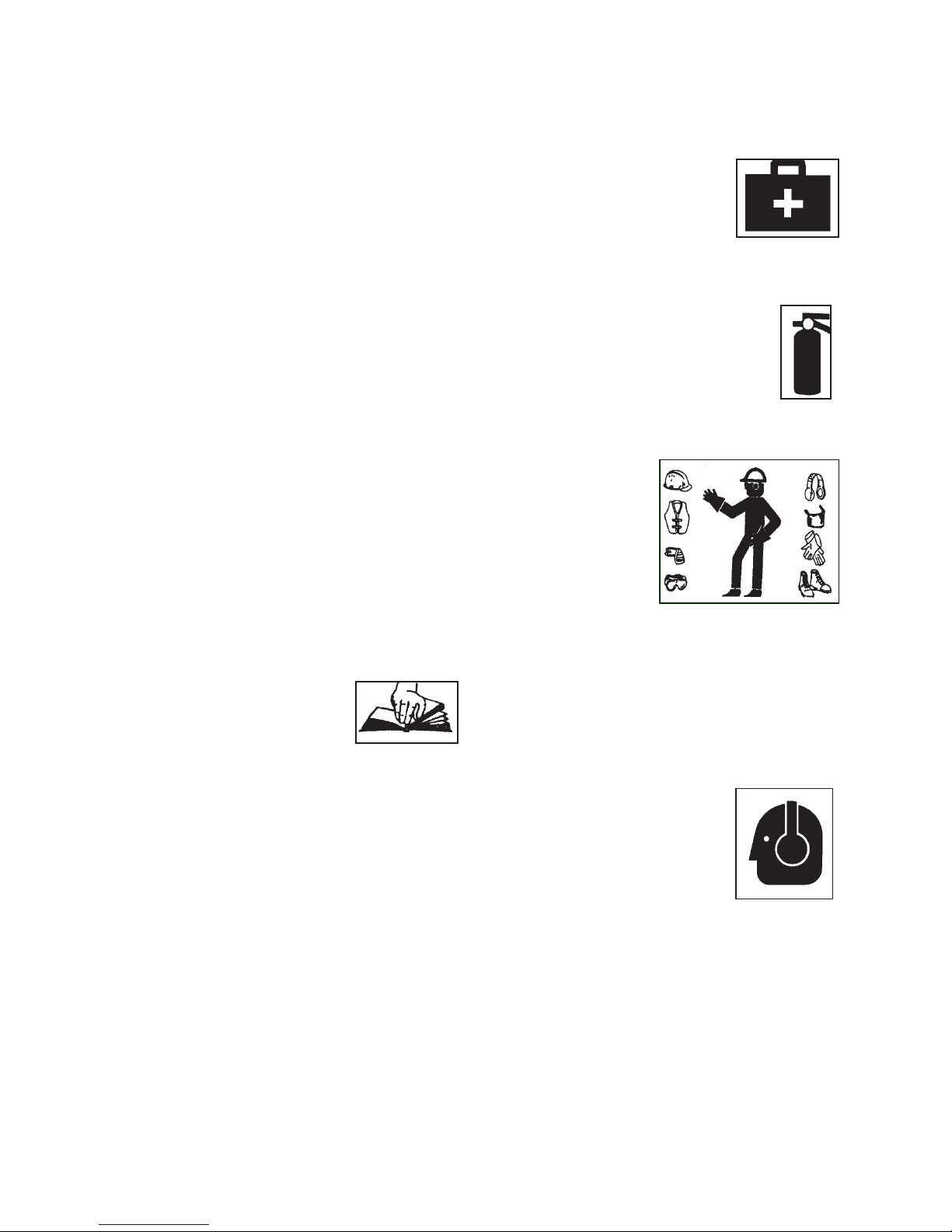
• DO have a rst-aid kit available
for use should the need arise
and know how to use it.
• DO read and understand all
safety signs located on the
machine before using, maintaining, adjusting
or cleaning the generator
• DO have a re extinguisher suitable
for electrical res available, should
the need arise and know how to use it.
• DO inspect and secure all guards
before starting.
• DO wear appropriate protective gear. This list
includes but is not limited to:
• Heavy gloves
• Hearing
protection
• Protective shoes
with slip resistant
soles
• Protective
glasses, goggles
or face shield
• DO prepare before servicing, adjusting,
repairing or unplugging:
• stop the machine, disconnect load
• shut off the engine,
• wait for all moving parts to stop
• clear the area of people, especially small
children.
• DO wear suitable ear protection for prolonged
exposure to excessive noise.
• DO operate on dry level ground
away from combustibles.
• DO NOT touch hot engine
parts, mufer, mufer cover,
engine body, engine oil, etc.
during operation and after the engine has been
shut off. Contact may cause burns.
• DO NOT modify the control panel wiring or any
grounding on the generator
• DO think SAFETY! Work SAFELY!
8

2.2 EQUIPMENT SAFETY GUIDELINES
Z94216
Safety of the operator and bystanders is one of the main concerns in designing and developing equipment.
However, every year many accidents occur which could have been avoided by a few seconds of thought and
a more careful approach to handling equipment. You, the operator, can avoid many accidents by observing
the following precautions in this section. To avoid personal injury or death, study the following precautions
and insist those working with you, or for you, follow them.
1. In order to provide a better view, certain
photographs or illustrations in this manual may
show an assembly with a safety shield removed.
However, equipment should never be used in
this condition. Keep all shields in place. If shield
removal becomes necessary for repairs, replace
the shield prior to use.
2. Replace any safety sign or instruction sign that
is not readable or is missing. Location of such
safety signs is indicated in this manual.
3. Never use alcoholic beverages or drugs which
can hinder alertness or coordination while using
this equipment. Consult your doctor about
using this machine while taking prescription
medications.
4. Under no circumstances should young
children be allowed to work with this
equipment. Do not allow persons to use
this until they have read this manual and
have developed a thorough understanding of
the safety precautions and of how it works.
Review the safety instructions with all users
annually.
5. This equipment is dangerous to children and
persons unfamiliar with its operation. The
operator should be a responsible, properly
trained and physically able person familiar with
machinery and familiar with this equipment's
operations. If the elderly are assisting with work,
their physical limitations need to be recognized
and accommodated.
6. Never exceed the limits of a piece of machinery.
If its ability to do a job, or to do so safely, is in
question - DON'T TRY IT.
7. Never run a generator indoors,
a generator’s exhaust contains
toxic carbon monoxide, which you
cannot smell or see. Breathing
carbon monoxide can be lethal.
8. Do not modify the equipment
in any way. Unauthorized
modication may result in serious
injury or death and may impair the
function and life of the equipment.
9. In addition to the design and conguration
of this equipment, including Safety Signs
and Safety Equipment, hazard control and
accident prevention are dependent upon the
awareness, concern, prudence, and proper
training of personnel involved in the operation,
transport, maintenance, and storage of the
machine. Refer also to Safety Messages and
operation instruction in each of the appropriate
sections of the engine and machine manuals.
Pay close attention to the Safety Signs afxed
to the machine.
10. Safe condition involves the following procedure:
• Flip main switch "off" or disconnect all loads
• Shut off the engine.
• Ensure all components have stopped moving.
Safe Condition procedure should be performed
before any service, maintenance work or
storage preparation.
9

2.3 SAFETY TRAINING
2.4 PREPARATION
1. Train all new personnel and review instructions
frequently with existing workers. Safety is a
primary concern in the design and manufacture
of our products. Unfortunately, our efforts to
provide safe equipment can be wiped out by a
single careless act of an operator or bystander.
2. In addition to the design and conguration
of equipment, hazard control and accident
prevention are dependent upon the awareness,
concern, prudence and proper training of
personnel involved in the operation, transport,
maintenance and storage of this equipment.
3. It has been said, "The best safety feature is an
informed, careful operator."
We ask you to be that kind
of an operator. It is the
operator's responsibility to
read and understand ALL
Safety and Use instructions in the manual and
to follow these. Accidents can be avoided.
4. Working with unfamiliar equipment can
lead to careless injuries. Read this manual
before assembly or using, to acquaint
yourself with the machine. If this machine
is used by any person other than yourself,
or is loaned or rented, it is the machine
owner's responsibility to make certain that
the operator, prior to using:
• Reads and understands the operator's
manuals.
• Is instructed in safe and proper use of
the equipment.
• Understands and knows how to perform
the "safe condition" procedure:
• Flip main switch "off" or disconnect all
loads
• Shut off the engine.
• Ensure all components have stopped
moving.
5. Know your controls and how to stop the engine
and machine quickly in an emergency. Read this
manual and the one provided with your engine.
6. Be certain only a properly trained and physically
able person will use the machinery. A person who
has not read and understood all using and safety
instructions is not qualied to use the machine.
An untrained operator exposes himself and
bystanders to possible serious injury or death.
If the elderly are assisting with the work, their
physical limitations need to be recognized and
accommodated.
1. Never use the engine and machine until the
operators have been adequately trained in the
safe operation of the machine and have read
and completely understand:
• Safety, Operation and Feature sections of
this manual,
• Engine Operator's Manual
• Each of the Safety Messages found on the
safety signs on the engine and machine.
2. Personal protection equipment including:
• safety glasses
• safety shoes
• gloves
• hearing protection
are recommended
during assembly,
installation,
operation, adjustment, maintaining, repairing,
removal, cleaning, or moving the generator.
Do not allow long hair, loose tting clothing or
jewellery to be around equipment.
3. PROLONGED EXPOSURE TO LOUD NOISE
MAY CAUSE PERMANENT HEARING LOSS!
Power equipment can often be noisy enough
to cause permanent, partial hearing loss. We
recommend that you wear
hearing protection on a fulltime basis. Noise over 85dB
on a long-term basis can
cause severe hearing loss.
Noise over 90db adjacent to
the Operator over a long-term
basis may cause permanent,
total hearing loss.
4. Clear working area of stones, branches or hidden
obstacles that might be hooked or snagged,
causing injury or damage.
5. Use only in daylight or good articial light.
6. Be sure machine is properly mounted, adjusted
and in good operating condition.
7. Ensure that all safety shielding and safety signs
are properly installed and in good condition.
8. If fuel is on site, store it well away from the
machine and ammable materials.
9. Perform the "PreOperation Checklist" procedure
before starting work.
10

2.5 MAINTENANCE SAFETY
1. Good maintenance is your responsibility. Poor
maintenance is an invitation to trouble.
2. Follow good shop practices.
• Keep service area clean
and dry.
• Be sure electrical outlets
and tools are properly
grounded.
• Use adequate light for
the job at hand.
3. Make sure there is plenty of
ventilation. Never operate the machine or the
towing vehicle in a closed building. The exhaust
fumes may cause asphyxiation.
4. Put the machine in safe condition before
working on this machine:
• Flip main switch "off" or disconnect all loads
• Shut off the engine.
• Ensure all components have stopped moving.
5. Allow the engine to cool before performing
maintenance, engine components and oil may
be hot enough to cause injury.
6. Never work under equipment unless it is blocked
securely.
7. When performing any service or maintenance
work always use personal protection devices
such as
• safety glasses,
• hand protection - gloves
• hearing protectors
• safety shoes
8. Where replacement parts are necessary for
periodic maintenance and servicing, genuine
factory replacement parts must be used to restore
your equipment to original specications. The
manufacturer will not be responsible for injuries
or damages caused by use of unapproved parts
and/or accessories.
9. An appropriate re extinguisher (electrical res)
and rst aid kit should be kept readily accessible
while performing maintenance on this equipment.
10. Inspect and tighten all bolts, nuts and screws
and check that all electrical and fuel connections
are properly secured to ensure generator is in
a safe condition.
11. When completing a maintenance or service
function, make sure all safety shields and devices
are installed before placing the generator in
service.
12. When performing
maintenance on this
equipment always have at
least 2 workers present. Do
not work alone in case an
emergency should arise.
13. When cleaning any parts, do not use gasoline
but use regular cleanser.
14. Always use proper tools, that are in good
condition. Make sure you understand how to
use them, before performing any service work.
2.6 BATTERY SAFETY
Caution: Poison / Danger - Causes
Severe Burns. The battery contains
sulphuric acid. Avoid contact with skin,
eyes or clothing. Keep out of reach of
children.
1. Wear gloves and safety glasses or face shield
when working on or near batteries.
2. Use a battery carrier to lift the battery or place
hands at opposite corners to avoid spilling
acid through the vents.
3. Avoid contact with battery electrolyte:
External Contact: Flush immediately with
water.
Eye Contact: Flush with water for 15 minutes.
Get prompt medical attention. Clean up any
spilled electrolyte immediately.
4. Avoid contact with battery posts, terminals
and related accessories, they contain lead
and lead compounds, chemicals known to
cause harm. Wash hands immediately after
handling battery.
5. Keep all sparks and ames away from batteries, as gas given off by electrolyte is explosive.
6. To avoid injury from spark
or short circuit, disconnect
battery ground cable before
servicing any part of the electrical system.
7. FROZEN BATTERIES CAN
EXPLODE and result in death
or serious injury. DO NOT
jump start / charge a frozen
battery. Let battery thaw before charging.
8. DO NOT use or charge the battery if its uid
level is below the LOWER mark.
11

Z94216
Z94222
2.7 REFUELING SAFETY
1. Allow the engine to cool if the generator has
been in operation.
2. Refuel only outdoors in a well-ventilated area
with the engine off.
3. Never smoke near fuel, and keep other ames
and sparks away.
4. Do not overll the fuel tank.
5. Always store fuel in an approved
container. Make sure that any
spilled fuel has been wiped up
before starting the engine.
2.8 OPERATING SAFETY
1. Please remember it is important that you read
and heed the safety signs on the generator.
Clean or replace all safety signs if they cannot
be clearly read and understood. They are there
for your safety, as well as the safety of others.
The safe use of this machine is strictly up to
you, the operator.
2. All things with moving parts are potentially
hazardous. There is no substitute for a cautious,
safe-minded operator who recognizes potential
hazards and follows reasonable safety practices.
The manufacturer has designed this generator
to be used with all its safety equipment properly
attached, to minimize the chance of accidents.
Read and understand operator's manual before
starting, to make sure you have all safety
equipment attached and operational.
3. Close and secure all covers, guards, deectors
and shields before starting and operating.
4. Never run a generator indoors,
a generator’s exhaust contains
toxic carbon monoxide, which you
cannot smell or see. Breathing
carbon monoxide can be lethal.
5. Do not operate near openings to
any building that can be occupied
in order to help avoid the exhaust
hazard.
6. Personal protection equipment
including hearing protection, safety glasses,
safety shoes, and gloves are recommended
during assembly, installation, operation,
adjustment, maintaining, repairing, removal,
or moving.
7. Inspect electrical harness, and controller to
ensure they are in good condition before
operating to maintain control.
8. Keep the generator dry. Operate on a dry surface
under an open well ventilated, covered structure.
9. Never use alcoholic beverages or drugs which
can hinder alertness or coordination while
operating this equipment. Consult your doctor
about operating this machine while taking
prescription medications.
10. Never allow children or unauthorized people to
operate or be around this machine.
11. Plug appliances directly into generator or use a
heavy-duty outdoor-rated extension cord. Make
sure entire extension cord is free of cuts or
tears and the plug has all 3 prongs, especially
a grounding pin.
12. If necessary to connect generator to house
wiring to power appliances, have a qualied
electrician install appropriate equipment. Or,
your utility company may be able to install an
appropriate transfer switch.
13. Keep the working area clean and free of debris
to prevent tripping. Operate only on level
ground.
14. Parts of a generator become very hot during
operation and remain hot for a
time after stopping the engine.
Be careful not to touch the mufer
while it is hot. Let the engine
cool before storing the generator
indoors.
15. To prevent a possible re, keep
the generator at least 3 feet (1
meter) away from building walls
and other equipment during
operation. Do not place ammable objects close
to the engine.
16. NEVER plug the generator into a wall outlet.
This practice, known as backfeeding, can cause
an electrocution risk to utility workers and others
served by the same utility transformer.
12

Z94221
2.9 TRANSPORT SAFETY
1. Comply with Provincial / state and local laws
governing safety and transporting of machinery
on public roads.
2. Do not exceed a safe travel speed. Slow down
for rough terrain and cornering.
3. Do not transport or move the generator with the
engine running.
4. Inspect all access panels and guards to ensure
they are secured.
5. If the generator has been running, allow the
engine to cool for at least 15 minutes before
loading the generator on the transport vehicle.
A hot engine and exhaust system can burn you
and may ignite some materials.
6. Ensure the fuel tank cap is on tight and keep the
generator level when transporting to reduce the
possibility of fuel leakage.
7. Move the fuel valve lever to the OFF position.
8. When using ropes or tie-down straps to secure
the generator for transportation, be sure to only
use the frame bars as attachment points. Do
not fasten ropes or straps to any portions of the
generator body.
9. Do not drink and drive.
10. Just before transport, perform a circle check to
ensure everything is safe and secure.
2.11 ELECTRICAL SAFETY
1. The generator produces enough
electric power to cause a serious
shock or electrocution if misused.
2. Using a generator or electrical
appliance in wet conditions
(rain or snow), or near a pool
or sprinkler system, or when
your hands are wet, could
result in electrocution. Keep the
generator and the immediate
area dry.
3. If the generator has been outdoors, unprotected
from the weather, check all of the electrical
components on the control panel before
each use. Moisture can cause a short circuit
in electrical components that could result in
electrocution.
4. Do not connect to a building’s electrical system
unless an transfer / isolation switch has been
installed by a qualied electrician.
5. NEVER tamper with the factory settings of
the engine or engine governor. Engine speed
controls the frequency portion of the electrical
output (60hZ). Personal injury or damage to the
engine or equipment can result if operating in
speed ranges above the maximum or below the
minimum allowable.
2.10 STORAGE SAFETY
1. Store the unit in a well vented area away from
human activity.
2. If possible, store in a dry area, avoid storage
areas with high humidity, because that promotes
rust and corrosion.
3. Avoid any area where power tools are operated
or spark-producing electric motors.
4. Do not allow children to play on or around the
stored machine.
5. Place the generator on a level surface. Tilting or
laying it on its side can cause fuel or oil leakage.
Support the frame with planks if required.
6. Allow the engine / exhaust to cool. A hot engine
and exhaust system can ignite or melt some
materials.
7. With the engine and exhaust system cool, cover
the generator to keep out dust.
8. Do not use a nonporus sheet as a dust cover. A
nonporous cover will trap moisture around the
generator, promoting rust and corrosion.
13

2.12 GAS MOTOR SAFETY
14. DO NOT crank engine with spark plug removed.
If engine is ooded, crank until engine starts.
BEFORE STARTING ENGINE, READ
AND UNDERSTAND THE OPERATING
AND MAINTENANCE INSTRUCTIONS
THAT CAME WITH YOUR ENGINE.
WARNING: DO NOT
1. DO NOT run engine in an enclosed area.
Exhaust gases contain carbon monoxide, an
odourless and deadly poison.
2. DO NOT place hands or feet near moving or
rotating parts.
3. DO NOT store, spill, or use gasoline near an
open ame, or devices such as a stove, furnace,
or water heater which use a pilot light or devices
which can create a spark.
4. DO NOT refuel indoors where area is not well
ventilated. Outdoor refuelling is preferred.
5. DO NOT refuel while engine is running. Allow
engine to cool for 5 minutes before refuelling.
Store fuel in approved safety containers.
15. DO NOT strike ywheel with a hard object or
metal tool as this may cause ywheel to shatter
in operation. Use proper tools to service engine.
16. DO NOT operate engine without a mufer.
Inspect periodically and replace, if necessary.
If engine is equipped with a mufer deector,
inspect periodically and replace, if necessary
with correct deector.
17. DO NOT operate engine with an accumulation
of grass, leaves, dirt or other combustible
materials in the mufer area.
18. DO NOT use this engine on any forest covered,
brush covered, or grass covered unimproved
land unless a spark arrester is installed on
the mufer. The arrester must be maintained
in effective working order by the operator. In
the state of California the above is required
by law (Section 4442 of the California Public
Resources Code). Other states may have
similar laws. Federal laws apply on federal land.
19. DO NOT touch hot mufer, cylinder or ns
because contact may cause burns.
6. DO NOT remove fuel tank cap while engine is
running.
7. DO NOT operate engine if gasoline is spilled.
Move machine away from the spill and
avoid creating any ignition until gasoline has
evaporated.
8. DO NOT smoke while lling fuel tank.
9. DO NOT choke carburetor to stop engine.
Whenever possible, gradually reduce engine
speed before stopping.
10. DO NOT run engine above rated speeds. This
may result in injury.
11. DO NOT tamper with governor springs,
governor links or other parts which may
increase the governed speed.
12. DO NOT tamper with the engine speed selected
by the original equipment manufacturer.
13. DO NOT check for spark with spark plug or
spark plug wire removed.
20. DO NOT run engine with air cleaner or air
cleaner cover removed.
WARNING: DO
1. ALWAYS DO remove the wire from the spark
plug when servicing the engine or equipment
to prevent accidental starting. Disconnect
the negative wire from the battery terminal if
equipped with a 12 volt starting system.
2. DO keep cylinder ns and governor parts free of
grass and other debris which can affect engine
speed.
3. DO examine mufer periodically to be sure it is
functioning effectively. A worn or leaking mufer
should be repaired or replaced as necessary.
4. DO use fresh gasoline. Stale fuel can gum
carburetor and cause leakage.
5. DO check fuel lines and ttings frequently for
cracks or leaks. Replace if necessary.
14

2.13 SIGN-OFF FORM
SurgeMaster follows the general Safety Standards specied by the American Society of Agricultural and
Biological Engineers (ASABE) and the Occupational Safety and Health Administration (OSHA). Anyone
who will be using and/or maintaining the Portable Generator must read and clearly understand ALL Safety,
Usage and Maintenance information presented in this manual.
Do not use or allow anyone else to use this generator until such information has been reviewed. Annually
review this information before the season start-up.
Make these periodic reviews of SAFETY and OPERATION a standard practice for all of your equipment.
We feel that an untrained operator is unqualied to use this machine.
A sign-off sheet is provided for your record keeping to show that all personnel who will be working with the
equipment have read and understand the information in the Operator’s Manual and have been instructed
in the operation of the equipment.
SIGN-OFF FORM
DATE
EMPLOYEES SIGNATURE EMPLOYERS SIGNATURE
15

3 SAFETY SIGNS
Z94221
Z94225
1. Keep safety signs clean and legible at all times,
2. Replace safety signs that are missing or have become illegible.
3. Replaced parts that displayed a safety sign should also display the current sign.
4. Safety signs in Section 3 each have a part number displayed with it. Use this part number when ordering
replacement parts.
5. Safety signs are available from your authorized Distributor or Dealer Parts Department or the factory.
3.1 HOW TO INSTALL SAFETY SIGNS:
• Be sure that the installation area is clean and dry.
• Be sure temperature is above 50°F (10°C).
• Determine exact position before you remove the backing paper.
• Remove the smallest portion of the split backing paper.
• Align the sign over the specied area and carefully press the small portion with the exposed sticky
backing in place.
• Slowly peel back the remaining paper and carefully smooth the remaining portion of the sign in place.
• Small air pockets can be pierced with a pin and smoothed out using the piece of sign backing paper.
3.2 SAFETY SIGN EXPLANATIONS:
Caution: A generator produces enough
electrical power to cause serious shock
or electrocution. Using a generator in
wet conditions such as in rain or snow,
, or with wet hands could result in
electrocution. Keep the generator dry.
Caution: Do not refuel the machine
while smoking or when near open ame
or sparks. Fuel is highly ammable,
handle with care.
Caution: Parts of a generator become
very hot during operation and remain hot
for a time after stopping the engine. Be
careful not to touch the mufer while it is
hot. Let the engine cool before storing the
generator indoors.
Z94222
Using a generator indoors CAN KILL YOU IN MINUTES. Generator
Exhaust contains carbon monoxide. This is a poison you cannot see
L'utilisation d'un générateur àl'intérieur PEUT VOUS FAIRE MOURIR
NEVER use inside a home or
maisonoudans dessecteurs
partiellement inclustelsque des
garages,MÊMESIles portes et
DANGER!
EN MINUTES. L'échappement contient le monoxyde de carbone,
garage, EVEN IF doors and
N'employerJAMAIS dans la
lesfenetressoientouvertes.
or smell.
Ceci est un toxiqueque vous ne pouveznivoirnisentir.
Only use OUTSIDE and far
away from windows, doors,
windows are open.
and vents.
Employer seulemer DEHORS
et loin de fenêtres, desporte
et des ventilateurs.
Danger: Never run a
generator indoors, a
generator’s exhaust contains
toxic carbon monoxide,
which you cannot smell
or see. Breathing carbon
monoxide can be lethal.
Caution: Read and understand ALL
safety and operating instructions in
the manual, read and understand ALL
safety labels located on the machine.
The most important safety device on this
equipment is an informed SAFE operator.
NEUTRAL BONDED TO FRAME
NEUTRE RACCORDÉ AU BÂTI
Note: This is a
safety feature and
Z94170
indicates that the
neutral line of the electrical circuit has been
bonded to the frame of the generator.
16

3 SAFETY SIGN LOCATIONS
Z94215
!
The types of safety signs and locations on the equipment are shown in the illustrations that follow. Good
safety requires that you familiarize yourself with the various safety signs, the type of warning and the area,
or particular function related to that area, that requires your SAFETY AWARENESS.
• Think SAFETY! Work SAFELY!
Z94255 On Both Sides
Models Without Electric
Start
DANGER!
Using a generator indoors CAN KILL YOU IN MINUTES. Generator
Exhaust contains carbon monoxide. This is a poison you cannot see
L'utilisationd'ungénérateur àl'intérieur PEUT VOUS FAIRE MOURIR
EN MINUTES. L'échappement contient le monoxyde de carbone,
or smell.
Ceci est un toxiqueque vous ne pouvez ni voir ni sentir.
Using a generator indoors CAN KILL YOU IN MINUTES. Generator
Exhaust contains carbon monoxide. This is a poison you cannot see
L'utilisationd'ungénérateur àl'intérieur PEUT VOUS FAIRE MOURIR
EN MINUTES. L'échappement contient le monoxyde de carbone,
DANGER!
or smell.
Ceci est un toxiqueque vous ne pouvez ni voir ni sentir.
NEVER use inside a home or
garage, EVEN IF doors and
windows are open.
N'employerJAMAIS dans la
maisonoudans dessecteurs
partiellement inclustelsque des
garages,MÊMESIles portes et
les fenetressoientouvertes.
0°
Only use OUTSIDE and far
away from windows, doors,
and vents.
Employer seulemer DEHORS
et loin de fenêtres, desporte
et des ventilateurs.
Z94225
Z94252 On Both Sides
Models With Electric
Start
Z94255
NEVER use inside a home or
garage, EVEN IF doors and
windows are open.
N'employerJAMAIS dans la
maisonoudans dessecteurs
partiellement inclustelsque des
garages,MÊMESIles portes et
les fenetressoientouvertes.
REMEMBER - If safety signs have been damaged, removed, become illegible or parts replaced without
safety signs, new signs must be applied. New safety signs are available from your authorized dealer.
Only use OUTSIDE and far
away from windows, doors,
and vents.
Employer seulemer DEHORS
et loin de fenêtres, desporte
et des ventilateurs.
Z94225
Z94222
Z94216
Z94221
Z94252
17

4 OPERATION & FEATURES
OPERATING SAFETY
• Read and understand operator's manual before
starting. Review safety instructions annually.
• Stop and disable engine, and wait for all moving
parts to stop before servicing, adjusting or
repairing.
• To prevent electrical shocks, do not operate
this generator in the rain or with wet hands.
Generator should be kept dry and not operated
on wet or damp surfaces.
• Close and secure all guards, deectors and
shields before starting and operating.
• Do not connect the generator to a commercial
power line.
• Do not operate with damaged or defective
extension cords, or power cords. Protect
the cord from getting pinched or crushed if it
passes through a window or doorway.
• Use properly rated, grounded 3-prong
extension cords, tools, and appliances.
• Do not operate this generator indoors, or
in areas with poor ventilation. The exhaust
fumes contain carbon monoxide, a poisonous,
odourless, invisible gas. Prolonged exposure
can lead to unconsciousness and death.
• Do not refuel the engine while it is in operation
or still hot. Do not refuel the engine near
open ames, pilot lights or sparking electrical
devices (e.g. power tools, welders or grinders).
• To prevent a possible re, keep the generator
at least 1 meter (3 feet) away from building
walls and other equipment during operation.
• Do not place ammable objects close to the
engine.
• The engine should be refuelled in a well-lit,
adequately vented area. Avoid fuel spillage.
• Never allow children or unauthorized people
to operate or be around this machine.
• Keep the working area clean and free of
debris to prevent tripping. Operate only on
level ground.
• Do not cover the generator while in operation.
Overheating can result in damaged equipment.
• For storage, do not cover the generator until
it has cooled down completely.
• The ambient temperature should not exceed
100° F/40° C.
DO NOT attempt to crank or start the engine
before it has been properly lled with the recommended amount and type of oil.
4.1 TO THE NEW OPERATOR OR OWNER
The SurgeMaster Portable Generators are designed
to provide portable electrical power to equipment
that is not connected to the electrical grid system.
It is the responsibility of the owner or operator
to read this manual and to train all other
operators before they start working with the
machine. Follow all safety instructions exactly.
Safety is everyone's business. By following
recommended procedures, a safe working
environment is provided for the operator,
bystanders and the area around the work site.
Untrained operators are not qualied to use the
machine.
Many features incorporated into this machine are
the result of suggestions made by customers like
you. Read this manual carefully to learn how to use
the Generator safely and how to set it to provide
maximum field efficiency. By following these
instructions in conjunction with a good maintenance
program, your Portable Generator will provide many
years of trouble-free service.
4.1.1 SAFE CONDITION
Ensure all operators understand how to put the
machine in safe condition before working with
this machine,
• Flip main switch "off" or disconnect all loads
• Shut off the engine.
• Ensure all components have stopped moving.
18

4.2 MACHINE COMPONENTS
Engine
Alternator
Continuous
Maximum
SurgeMaster Portable Generators consists of
several models of generators. Although slightly
different for each model, controls and power outlets
are mounted in similar locations for convenient
access and operation.
Series Model
SHS3000 163cc 2.9 2100 2500
SHS3000R 163cc 2.9 2100 2500
SHS5000 270cc 4.9 4250 5000
SHS5000R 270cc 4.9 4250 4600
SHS7000 389cc 6.8 6250 6500
SHS7000R 389cc 6.8 6250 6700
SCS3000 163cc 2.9 2100 2500
SCS3000R 163cc 2.9 2100 2500
The unit is designed to provide electrical power
for work (Jobsite Rated series) or home (Backup
Power series). Each outlet is designed with a circuit
breaker to protect against overload. For protection
against electrical shocks from short circuits, the
machine is neutral bonded to the frame. The entire
assembly is mounted within the frame for added
protection and convenient access.
cc
kW
wattage
wattage
All SurgeMaster generators are CSA certied and have the safety feature
of the neutral conductor bonded to the frame, an OSHA requirement when
Engine
See "Controls" section
and engine owners
manual for more
engine information.
SCS5000 270cc 4.9 4250 5000
SCS5000R 270cc 4.9 4250 4600
SCS7000 389cc 6.8 6250 6500
SCS7000R 389cc 6.8 6250 6700
Note:
using portable electrical equipment on job sites.
Outlets
Circuit
Breaker
Frame
19

4.3 MACHINE BREAK-IN
Check and lubricate the machine per the schedule outline
Exhaust gas contains poisonous carbon monoxide. Never
Check all electrical connections. Replace, repair or clean
Make sure that all lids, guards and shields are in place,
Check condition of the battery and other electrical
Check the fuel level, Starting with a full tank will help to
Check engine fluid levels. Top up as required. Refer to the
Check the air filter
Check all power cords that will be used, ensure they are in
good repair.
Check that the alternator cooling air intake and discharge
4.4 PREOPERATION CHECKLIST
Although there are no operational restrictions on the
portable generator when used for the rst time, it is
recommended that the following mechanical items
be checked:
DO NOT attempt to crank or start the engine
before it has been properly lled with the
recommended amount and type of oil.
A. After operating for 1 hour:
1. Ensure the machine is in safe condition
before checking any components. (see
4.1.1)
2. Review the engine operators manual for
break-in.
3. Inspect the axle, tires, and wheels.
4. Torque all fasteners and hardware.
5. Check that the alternator cooling air intake
and discharge openings are free and
unblocked
6. Check condition of electrical components
and connectors. Keep all components /
connectors in good condition.
B. After operating for 8 hours:
1. Repeat steps 1 through 6 listed above.
(Section A)
2. Go to the normal servicing and maintenance
schedule as dened in the Maintenance
Section.
Air Discharge
Efcient and safe operation of the SurgeMaster
Portable Generator requires that each operator
reads and understands the use procedures and all
related safety precautions outlined in this section.
A PreOperation checklist is provided for the
operator. It is important for both the personal safety
and maintaining good mechanical condition that this
checklist is followed.
Before operating the SurgeMaster Portable
Generator and each time thereafter, the following
areas should be checked off:
Pre-Operation Checklist
in the Maintenance Section.
run the generator in an enclosed area. Be sure there is
adequate ventilation in the work area.
as required.
secured and functioning as designed.
components. Keep all components in good condition.
eliminate or reduce operating interruptions for refueling.
engine operators manual.
P
Air Intake
Ensure alternator openings
are free and unblocked
20
openings are free and unblocked

4.5 CONTROLS
Please review this section to familiarize yourself with the location and function of each control before starting.
The controls of the SurgeMaster generators are laid out so that they are easy to see and use. Familiarizing
yourself with the controls will enable you to take advantage of all the features available on the SurgeMaster
generators and apply them as conditions demand.
4.5.1 ENGINE CONTROLS
Always read the engine operator's manual supplied with the machine to familiarize yourself with its operating
and starting procedure details.
Generator Models And Engines:
SHS3000 & SHS3000R.......................GX160 SCS3000 & SCS3000R.......................GX160
SHS5000 & SHS5000R.......................GX270 SCS5000 & SCS5000R.......................GX270
SHS7000 & SHS7000R.......................GX390 SCS7000 & SCS7000R.......................GX390
The GX270 engine is described in the illustration below. The GX160 and GX390 are similar in layout with
the exception of the ignition switch on the GX390, which is located on the control panel.
1. Ignition Switch: This switch controls the electric power to the engine.(GX160 & GX270)
2. Throttle: The throttle is preset and locked to run at optimum RPM and is not adjustable. Engine RPM
directly affects output from the alternator, and therefore the RPM should never be adjusted.
3. Choke: (GX160) This slide lever controls the position of the choke. Close the choke for starting when
the engine is cold. Open the choke as the engine warms. Always fully open the choke when operating
the machine. (GX270 & 390 feature auto choke)
4. Starting Rope: Pull sharply on the starting rope T bar when starting the engine. Release the T bar
when engine is running.
5. Electric Start: (GX390) This switch controls the electric power to the engine, turn ignition switch located
on control panel to start the engine. Release the switch once engine starts.
6. Fuel Shut-Off Valve: This valve controls the ow of fuel to the engine. Turn the valve on when running
the engine and off when refuelling or not in use.
Choke
GX160
Fuel
Shut-off
Ignition Switch
Starting
Rope
GX270
GX390
Electric Start
21

4.5.2 ELECTRICAL PANEL FEATURES
SurgeMaster Standard Series generators have models available with a range of features. All standard
generators feature a reliable Honda engine, large fuel tanks for extended run time, and a heavy duty
wheeled frame with fold away handle.
Some models feature:
AVR (auto voltage regulation): an electronic circuit, designed to automatically maintain a constant voltage
level through a range of loads.
AVR indicator light shows the status of AVR:
• Indicator is on steady: Load is within range and voltage is being regulated.
• Indicator is ashing quickly: Load is too high and voltage is dropping out of
acceptable range.
Auto Idle: When there is no load detected, the AVR indicator light will blink slowly,
and the engine will slow to an idle. This feature is switchable on or off.
Full Power Feature: When the 240v leg is not used, turning on the full power feature utilizes the secondary
winding of the alternator (normally used for 240v) to increase the power capacity of all 120v outlets (5-20R
and L5-30). Amperage values in the specication chart are shown with the Full Power feature on. Turning
on the full power feature disables the 240v L14-30 receptacle.
Ground terminal: The generator ground terminal is connected to the
ground terminals of each receptacle and the frame of the generator.
Before using the ground terminal, consult a qualied electrician or
electrical inspector for any local codes that apply to the intended use of
the generator. Ground and neutral are bonded to the frame.
GROUD FAULT
SENSING MODULE
GCFI Protection: Jobsite Rated Series feature full panel GFCI protection.
The main breaker also functions as a ground fault circuit interrupter
(GFCI) which is able to detect an imbalance as small as 6 milliamps, and
it can react almost instantly to trip the circuit. GFCI circuit protection is a
requirement for OSHA.
GFCI Module Function And Testing: In a typical circuit, the current
returning to the power supply will be equal to the current leaving the
power supply. If the difference between the current leaving and current
returning through the GFCI exceeds 6 milliamps, the GFCI opens and
de-energizes the circuit.
Normal operating state:
• Power LED is green indicating power is on.
• Circuit breaker is at “on” position.
• Fault indicator LED is off.
Ground fault is detected:
• Power green LED will go out.
• Red fault led will start blinking.
• Circuit breaker will trigger to off position.
Note: An electrical overload
is indicated if the breaker
trips and the GFCI green
power light is still on.
• Switch off or disconnect the load, determine the source of the fault and correct.
• GFCI module will automatically reset, no need to press reset button.
• Turn on the circuit breaker.
• Reconnect the load.
TEST
TEST
P
O
W
E
R
RESET
F
A
U
L
T
RESET
WARNING
TEST BEFORE EACH USE
SEE INSTRUCTIONS
Test GFCI for proper operation before each use. Press test button. The circuit should be de-energized,
power green LED will go out, red fault led will start blinking. Push the reset button to reset. Do not operate
generator and have the GFCI module inspected by a qualied electrician if GFCI fails this test.
22

4.5.3 ELECTRICAL PANEL
SHS3000 & SHS3000R
One three prong twist lock outlet is used to
provide 120v power. One duplex outlet for
120v power. Full panel is protected by a 15
amp breaker.
125v L5-30
receptacle
SCS3000 & SCS3000R
15 amp main
breaker
125v duplex
receptacle
(5-20R)
AVR indicator
SHS3000R
only
Ground
terminal
15 amp main
breaker
One three prong twist lock outlet is used to
provide 120v power. One duplex outlet for 120v
power. Full panel is protected by a 15 amp
breaker and GFCI module.
125v L5-30
receptacle
2 x 125v duplex
receptacles (5-20R)
SHS5000 & SHS5000R
One three prong twist lock outlet is used to
provide 120v power. One four prong twist lock
outlet is used to provide 120/240v power. Two
duplex outlets for 120v power, protected by 15
amp pop up breakers. Full panel is protected by
a 17.5 amp breaker.
AVR indicator
SCS3000R
only
2 x 15 amp pop
up breaker
Full panel GFCI
module
125v duplex
receptacle
(5-20R)
Ground
terminal
125/250v L14-30
receptacle
125v L5-30
receptacle
Full power feature
Hourmeter
Ground
terminal
AVR / Auto
idle indicator.
AVR on
SHS5000R only
Auto idle
control switch
17.5 amp
main breaker
23

2 x 125v duplex
receptacles (5-20R)
2 x 15 amp pop
up breaker
Full panel GFCI
module
SCS5000 & SCS5000R
One three prong twist lock outlet is used to
provide 120v power. One four prong twist lock
outlet is used to provide 120/240v power. Two
duplex outlets for 120v power, protected by 15
amp pop up breakers. Full panel is protected by
a 17.5 amp breaker and GFCI module.
Hourmeter
Ground
terminal
2 x 125v duplex
receptacles (5-20R)
SHS7000 & SHS7000R
One three prong twist lock outlet is used to
provide 120v power. One four prong twist lock
outlet is used to provide 120/240v power. Two
duplex outlets for 120v power, protected by 15
amp pop up breakers. Full panel is protected by
a 26 amp breaker.
Hourmeter
Ground
terminal
AVR / Auto idle
indicator. AVR on
SCS5000R only
2 x 15 amp pop
up breaker
AVR / Auto idle
indicator. AVR on
SHS7000R only
125/250v L14-30
Full power feature
Auto idle
control switch
125/250v L14-30
Full power feature
Auto idle
control switch
receptacle
125v L5-30
receptacle
17.5 amp
main breaker
receptacle
125v L5-30
receptacle
26 amp main
breaker
2 x 125v duplex
receptacles (5-20R)
SCS7000 & SCS7000R
One three prong twist lock outlet is used to
provide 120v power. One four prong twist lock
outlet is used to provide 120/240v power. Two
duplex outlets for 120v power, protected by 15
amp pop up breakers. Full panel is protected by
a 26 amp breaker and GFCI module.
Hourmeter
24
Ground
terminal
2 x 15 amp pop
up breaker
AVR / Auto idle
indicator. AVR on
SCS7000R only
Full panel GFCI
module
Auto idle
control switch
125/250v L14-30
receptacle
125v L5-30
receptacle
Full power feature
26 amp main
breaker

CIRCUIT BREAKERS:
Z94221
Z94252
Outlets on the electrical panel are protected
with circuit breakers to prevent overloading the
circuit. If a breaker trips, reduce the load before
re-setting the breaker. The pop out breakers
control duplex outlets only. The main circuit
breaker controls entire panel. On GFCI models,
GFCI controls entire panel.
• If a breaker trips:
• the breaker reset pops out or switch trips,
• switch off or disconnect the load,
determine the source of the over load
and correct,
• allow the breaker to cool,
• depress the breaker button or reset
switch to reset,
• turn on or reconnect the load
Pop out breakers
Main circuit
breaker
GFCI module
Note: For GFCI full panel protected models: A
ground fault is indicated if the breaker trips and the
GFCI red fault light is on.
OPERATING HINTS:
• Position frame on a level area to minimize
the chance of spilling fuel and maximize
the fuel capacity of the tank. Spilled fuel
can be ignited by a spark from the electrical
power system.
• Do not refuel while the engine is running.
Wait until the unit has cooled before refuelling.
• Keep the working area neat and clean
to prevent slipping and tripping. Prevent
accidents at the work site.
• Always keep the generator and connections
dry, do not let water pool around the
generator or connections to prevent potential
electrocution hazard.
• Position the generator under cover to protect
it from rain or bad weather.
• Do not operate when the ambient temperature
exceeds 100° F (40° C) to prevent overheating.
• Do not cover the unit during operation to
prevent overheating.
IMPORTANT
A circuit breaker that trips
repeatedly indicates a
problem.
Generator in optimum
working conditions
DANGER
Carbon Monoxide Hazard:
Never run a generator indoors. A
generator’s exhaust contains toxic
carbon monoxide, which you cannot
smell or see. Breathing carbon
monoxide can be lethal.
Z94216
25

4.6 ELECTRICAL LOAD
below maximum
Starting
Watts
Running
Watts
Load Calculation Example
4.6.1 WATTAGE AND LOAD
Your SurgeMaster generator has two wattage
(power) specications that need to be considered
when you are connecting loads: continuous watts
and maximum watts.
At the same time there are two different types of
loads, resistive and reactive.
REACTIVE LOAD
Generally a tool or appliance that contains an
electric motor is a reactive load, Reactive loads
have two modes of operation: startup and running.
An electric motor starting watts (reactive load)
could possibly require up to 3 x its running watts
at start up.
In other words wattage will spike at starting and
level off to running (continuous) wattage when it is
operating normally. (See wattage chart)
RESISTIVE LOAD
A resistive load is lighting, hot plate, TV, etc,
Resistive loads generally will not spike and starting
wattage is the same as running wattage. (See
wattage chart)
CONTINUOUS WATTAGE
Continuous wattage is the wattage range that can be
safely generated by the alternator for an extended
period.
4.6.2 CALCULATING LOAD
When calculating load in watts, you will need to
determine two wattage values:
• running wattage + starting wattage: determine
the starting wattage of your reactive loads and
add them to the running wattage of your resistive
loads.
• running wattage only: add up the running
wattage of both the resistive and reactive loads.
Generator Spec: 2000 maximum watt, 1500 continuous watt
Qty Load
1
Refrigerator/Freezer 1200 192
load calculation ex-
1
Furnace Fan (1/8 hp) 500 300
ample
6
Lighting (40w ea) 240 240
Totals
The example totals match the second combination
on the chart, and shows that the run status is OK.
Wattage Combination Status
total starting wattage + total running wattage is
within the continuous rating
total starting wattage is over the continuous
rating but below maximum, and total running
wattage is within continuous rating
1940 732
OK
OK
MAXIMUM WATTAGE
Maximum wattage is the wattage range the
generator can produce but for only short periods
of time (electric motor starting). Drawing maximum
wattage for extended periods will cause the breaker
to trip.
total starting wattage is over the continuous &
maximum rating, and total running wattage is
within continuous rating
total starting wattage is over the continuous &
maximum rating, and total running wattage is
over continuous rating
both the total starting wattage and total running
wattage are over the continuous rating but
Stop
Stop
Stop
26

50,000 BTU
4.6.4 WATTAGE CHART
The chart below contains general wattage information, and is intended to be used as a guide only.
For some electrical, and electronic appliances, you can determine the power needed by looking at the data
tag supplied by the manufacturer.
Most products and all electrical motors should have a data tag attached to their bodies that give volts and
amps and may contain wattage information.
To determine the wattage, use this formulae:
Amps x Volts = Watts
(See wattage chart)
Household Wattage Approx. Starting Running Industrial Motors Approx. Starting Running
Coffee Maker 600 600 Split Phase ¼ hp 1700 400
Dish Washer 540 216 Split Phase ½ hp 2600 600
Electric Frying Pan 1500 1500 Capacitor Start Induction Run ¹/
Electric Range 8" Element 2100 2100 Capacitor Start Induction Run 1 hp 2300 1000
Microwave Oven (650 watts) 1000 1000 Capacitor Start Capacitor Run 1-½ hp 4200 1600
Refrigerator/Freezer (Energy Star) 1200 132-192 Fan - ¼ hp 1200 650
Automatic Washer 3400 1200
Clothes Dryer (Electric) 6750 5400
Furnace Fan (1/8 hp) 500 300 Air Compressor (½ hp) 1600 975
Furnace Fan (1/6 hp) 750 500 Air Compressor (1 hp) 4500 1600
Furnace Fan (1/4 hp) 1000 600 Bench Grinder (8") 2500 1400
Furnace Fan (1/3 hp) 1400 700 Hand Drill (½") 900 600
Furnace Fan (1/2 hp) 2350 875 Pressure Washer (1 hp) 3600 1200
Lighting Circular Saw (7 - ¼") 2300 1400
Radio 50-200 50-200 Electric Chain Saw (14", 2hp) 1100 1100
Sump Pump (1/3 hp) 1300 800 230 Amp AC (at 100 amp) 7800 7800
Sump Pump (1/2 hp) 2150 1050 Table Saw (10 Inches) 4500 1800
Television: tube / 43" flat screen 300 / 190 300 / 190 Drill (3/8", 4 amps) 600 440
Air Conditioner (10000 BTU) 2200 1500 Drill (1/2", 5.4 amps) 900 600
Laptop Computer 200-250 200-250
Desktop Computer 600-800 600-800
Monitor (LCD style) 30 30 Electric Fence (25 miles) 250
Printers Milk Cooler 1800 1100
Ink Jet / Ink Jet Multi Function 20 / 250 20 / 250 Milker (Vacuum Pump, 2hp) 2300 1000
DVD Player 350 350
Satelite Receiver 250 250 90,000 BTU 725 500
Fan (portable) 120 40 150,000 BTU 1000 625
add up various wattages
Laser 400-850 400-850 Portable Heater(Kerosene / Diesel
Contractor Approx. Starting Running
Farm Equipment Approx. Starting Running
Battery Charger
60 Amp w/ 250 Amp Boost 1500/5750 1500/5750
100 Amp w/ 300 Amp Boost 2400/7800 2400/7800
Electric Welder (200 Amp AC) 9000 9000
3 hp 975 450
600 400
15 Amp 380 380
27

5 FIELD OPERATION
OPERATING SAFETY
• Read and understand operator's manual before
starting. Review safety instructions annually.
• Stop and disable engine, remove ignition key
and place in your pocket and wait for all moving
parts to stop before servicing, adjusting or
repairing.
• To prevent electrical shocks, do not operate
this generator in the rain or with wet hands.
Generator should be kept dry and not operated
on wet or damp surfaces.
• Close and secure all guards, deectors and
shields before starting and operating.
• Do not connect the generator to a commercial
power line.
• Do not operate with damaged or defective
extension cords, or power cords. Protect
the cord from getting pinched or crushed if it
passes through a window or doorway.
• Use properly rated, grounded 3-prong
extension cords, tools, and appliances.
• Do not operate this generator indoors, or
in areas with poor ventilation. The exhaust
fumes contain carbon monoxide, a poisonous,
odourless, invisible gas. Prolonged exposure
can lead to unconsciousness and death.
• Do not refuel the engine while it is in operation
or still hot. Do not refuel the engine near
open ames, pilot lights or sparking electrical
devices (e.g. power tools, welders or grinders).
• To prevent a possible re, keep the generator
at least 1 meter (3 feet) away from building
walls and other equipment during operation.
• Do not place ammable objects close to the
engine.
• The engine should be refuelled in a well-lit,
adequately vented area. Avoid fuel spillage.
• Never allow children or unauthorized people
to operate or be around this machine.
• Keep the working area clean and free of
debris to prevent tripping. Operate only on
level ground.
• Do not cover the generator while in operation.
Overheating can result in damaged equipment.
• For storage, do not cover the generator until
it has cooled down completely.
• The ambient temperature should not exceed
100° F/40° C.
The operator has the responsibility of being
familiar with all operating and safety procedures
and following them.
Although the Portable Generator is easy to use, each
operator should review this section to familiarize
himself with the detailed safety and operating
procedures. When using this machine, follow this
procedure:
5.1 PREPARE
• Clear the area of bystanders, especially small
children.
• Each operator must be trained and familiar with
the set up and operation of the generator and
its components.
• Review the machine components.
(see Section 4.2)
28
• Review and follow the PreOperation Checklist.
(see Section 4.4).
• Review operation and function of the controls.
(see section 4.5)
• Survey the work site, move to a clear, level work
area and position at the work site. Do not start
the generator until it is in position.
• Review loads section. (see section 4.6).
Ensure all operators understand how to put the
machine in safe condition before working with this
machine,
• Flip main switch "off" or disconnect all loads
• Shut off the engine.
• Ensure all components have stopped moving.

5.2 START
Please review the engine controls section and the engine owners manual for starting and stopping the
engine.
5.2.1 STARTING THE GENERATOR:
• Ensure the main power switch / breaker is
in the "off" position or turn all the appliances
or electrical loads off.
• Plug in power cords from appliances or
loads.
• Ensure the cooling vents around the
alternator are free and not blocked
• Pull start: Turn on the ignition switch, pull
sharply on the starting rope T bar to start the
engine. (Refer to engine manual for detailed
engine starting procedure.)
Electric start (GX390): Turn ignition
switch located on control panel to start the
engine. Release the switch once engine
starts.
• Run the engine for a few moments until it
warms up.
• Flip the main switch / breaker to "on", or
switch appliances or electrical loads on.
5.2.2 STOPPING:
• Flip the main power switch / breaker to the
"off" position or turn all the appliances or
electrical loads off.
• Run the engine for a few moments to allow
the engine to cool.
• Switch engine off, unplug all appliances or
loads.
5.2.3 EMERGENCY STOPPING:
• Immediately ip off the main breaker
• Turn the engine off.
• Correct the emergency condition before
resuming work and re-starting the engine.
5.2.4 TERRAIN:
The generator works well in a wide variety
of operating conditions but it should always
be positioned on a level surface. When the
frame is level, fuel spillage is minimized and
the gas tank capacity is maximized. Do not
operate unless the frame is level.
5.2.5 WEATHER:
• Do not operate in the rain, in damp wet
conditions or with wet hands. Keep the
generator and work area dry to prevent
shocks and shorts. Use properly rated,
grounded 3-prong extension cords, tools,
and appliances.
• Do not operate at temperatures above
100° F (40° C) to prevent overheating of the
engine or generator. Always run for a few
minutes without an electrical load to help
cool the components before shutdown.
5.2.6 ELECTRICAL LOADS:
The generator is ideally suited to camping,
farm, household, workshop, construction site
or anywhere that back-up power is required.
In order to determine the power requirements
of your appliance, refer to section 4.6.
If the power draw for the appliance exceeds
the outlet capacity, the circuit breaker will be
tripped. Reduce the current draw and reset
the breaker before resuming operation.
5.2.7 COMPONENT CONDITION:
Always use electrical components that are
in good condition. Do not use electrical
cords, plugs and connectors that are frayed,
damaged, cracked or not in good condition.
Electrical components that are not in good
condition can lead to shocks, shorts or
sparking. Any of these conditions can create
and lead to an undesirable or unsafe situation.
5.2.8 ELECTRICAL HAZARDS:
The generator is designed to generate an
electrical current at a high enough power level
to get meaningful work done. However, power
at these levels also includes the possibility of
electrical hazards. Some things to remember
about electrical hazards include but are not
limited to:
• Keep all electrical components in good
condition.
• Do not operate with frayed, cracked or
damaged parts.
• Do not operate if operating in damp or wet
conditions.
• Do not operate with wet hands.
29

5.2.9 ELECTRICAL CORDS
Power cords are rated by AWG number. The
lower the AWG number, the thicker the wire
(gauge). The thicker the wire the more wattage
can travel through it.
Using underrated power cords to supply power
to electrical devices may cause over current
draw, trip a breaker and potentially damage
your device.
Depending on the amp draw or wattage of
your appliance, the gauge of the wire in your
extension cords becomes a factor in the length
of the cord you can use.
Because a wire can cause resistance to the
power ow, the thinner the wire, the more the
resistance. Similarly, the longer the wire, the
more the resistance.
Resistance due to the cord thickness or length
keeps the device from getting the power it
needs. You may have to increase the thickness
of the wire (lower number AWG), or shorten
the cord.
5.3 RESIDENTIAL
The most economical way to supply power during
a power outage is to use a portable generator and
run extension cords into the house to power chosen
appliances.
Never connect a generator to a house electrical
system without an appropriate transfer switch.
Known as "backfeeding" it is illegal, extremely
dangerous and potentially lethal.
A safer option is to use your generator in a standby
conguration. This requires an electrician to install a
generator sub panel, connected to the house's main
electrical panel. Prepare the generator, run a single
extension cord into the sub panel, ip the switch and
power the circuits you need.
This eliminates the risk of electrical “back feed”,
potentially injuring or killing utility workers repairing
downed power lines.
For standby installation: please note that
SurgeMaster generators have a "neutral bonded
to frame" feature, and requires connection by a
certied electrician when connecting the generator
to a house electrical system.
A portable electric generator can provide power for
fridges, freezers, sump pump, furnace fan small
kitchen appliances, power tools, lights and other
comforts of civilization when you are experiencing
a power outage.
When not required for home, portable generators
can be used to power recreational vehicles, or
put to work on construction sites that have no
electrical service, providing clean, reliable power to
operate saws, drills, air compressors, heaters, paint
sprayers and other AC-powered tools.
Electronics are sensative and may become
damaged if subjected to voltage and frequency
varitations. SurgeMaster generators equipped
with AVR (auto voltage regulation) help to regulate
voltage within a range, controlling dips in voltage
that could potentialy damage electronics.
However, appliances that have a reactive load
(electric motors in fridges, furnaces etc) cause a
momentary voltage drop at startup. AVR cannot
reacte fast enough compensate for the short drop
in voltage. Therefore it is important to consider what
loads are connected to your generator along with
your electronics.
For example if your 3000w generator has a 50%
constant load (lights, heaters etc) and a refridgerator
starts up (50% startup wattage) the result is a
momentarty voltage drop that could damage
sensative electronics.
Decreasing your constant load or increasing
the size of your generator will help the AVR to
regulate voltage. Another level of protection for
your electronics is have them connected to a UPS
(uninteruptable power supply) which will act as a
lter against voltage drops.
5.4 MOVING
5.4.1 TRANSPORTING:
When transporting from location to location, keep
the following points in mind:
• If the generator has been running, allow the
engine to cool for at least 15 minutes before
loading the generator on the transport vehicle.
A hot engine and exhaust system can burn you
and can ignite some materials.
• Keep the generator level when transporting to
reduce the possibility of fuel leakage. Move the
fuel valve lever to the OFF position.
• Do not lay the generator on its side when moving,
storing, or during operation. A hazardous
condition may be created by oil or fuel leaking.
• Transport when the fuel tank is empty or nearly
empty. Turn the fuel line off.
• When using ropes or tie-down straps to secure
the generator for transportation, be sure to only
use the frame bars as attachment points. Do
not fasten ropes or straps to any portions of the
engine or alternator.
30

5.4.2 LIFTING HOOK:
SurgeMaster standard generators feature a "sky
hook" lifting hook location for lifting with a crane.
Lifting locations are indicated by lift
hook labels and are located at the
centre of balance for the generator.
Lifting at this point is the safest way
to lift the generator. Have an extra
Lifting hook
Z94440
5.4.3 FOLDING HANDLE:
SurgeMaster standard generators are equipped
with a folding handle to allow for easy transportation.
To raise handle, simply lift the handle, and the latch
pins will release. Pivot handle upward until pins
engage to lock handle in raised position.
To lower handle, push down on the handle and the
latch pins will release. Pivot handle downward until
pins engage to lock handle in lowered position.
Latch pins
person with a guide rope attached to the generator
to prevent swaying.
Generators without sky hook location are not
designed to be lifted by crane.
Do not lift entire generator by folding handle. Folding
handle is not intended for motorized transport of
generator.
31

5.5 STORAGE
STORAGE SAFETY
• Store the unit in an area away from human
activity, or children playing
• Do not store near any tool, machine,
appliance that produces ame or sparks.
• Store the unit in a level area.
5.5.1 PLACING IN STORAGE
After use or when the machine will not be used
for a period of time, completely inspect all major
systems of the Portable Generator. Replace or
repair any worn or damaged components to prevent
any unnecessary down time at next use. PLEASE
REFER TO THE ENGINE OWNERS MANUAL TO
PREPARE THE ENGINE FOR STORAGE
Follow this procedure before storing:
1. Remove all plugs or electrical loads from the
electrical panel.
2. Thoroughly clean the machine with a damp cloth
to remove all dirt, mud or debris. Ensure all the
vents on the alternator are clean and clear.
3. Touch up all paint nicks and scratches to prevent
rusting.
4. Turn fuel valve off.
5. If the generator is to be stored for longer periods,
(over 6 months) follow the engine manufacturers
recommendations for storage preparation
6. Store the machine inside in cool dry area. Avoid
storage areas with high humidity, because that
promotes rust and corrosion.
7. Use a canvas tarp or similar material to keep
it covered and free of dust. Avoid plastic or
nonporus cover that will trap moisture and
promote corrosion.
8. If stored outside (not recommended), keep
it sheltered, store it on wooden blocks or a
wooden pallet, cover with a waterproof tarpaulin
and tie down securely.
9. Store in an area away from human activity.
10. Do not allow children to play around the stored
unit.
5.5.2 REMOVING FROM STORAGE
When removing this machine from storage, follow
this procedure:
1. Remove the tarpaulin if covered.
2. Review and follow the pre-operation checklist.
3. Check engine operators manual for engine
startup after storage.
IMPORTANT
If the machine has been stored for more
than 12 months with fuel, to prevent
hard starting, drain the fuel tank and
replace with fresh fuel.
Cleaned , prepared & ready for storage
(Typical)
32

6 SERVICE AND MAINTENANCE
MAINTENANCE SAFETY
• Good maintenance is your responsibility.
Poor maintenance is an invitation to trouble.
• Read the instructions before you begin,
and make sure you have the tools and
skills required. Do not smoke or have
sources of ignition nearby while performing
maintenance.
• Follow good shop practices.
- Keep service area clean and dry.
- Be sure electrical outlets and tools are
properly grounded.
- Use adequate light for the job at hand.
• Make sure there is plenty of ventilation.
Never operate the engine in a closed
building. The exhaust fumes may cause
asphyxiation.
• Before working on this machine, shut off the
engine, disconnect all loads, and turn fuel
valve off.
6.1 SERVICE
• Never work under equipment unless it is
blocked securely.
• A re extinguisher and rst aid kit should
be kept readily accessible while performing
maintenance on this equipment.
• Periodically tighten all bolts, nuts and
screws and check that all electrical and fuel
connections are properly secured to ensure
unit is in a safe condition.
• When completing a maintenance or service
function, make sure all safety shields and
devices are installed before placing unit in
service.
• Caution: Burns from hot parts. Let the
engine, alternator and exhaust system cool
before touching.
• Use only a non-ammable solvent, not
gasoline, to clean parts.
6.1.1 FLUIDS AND LUBRICANTS
1. Engine Oil:
See engine owners manual for full detail on oil
type specic to operating conditions and capacity.
2. Engine Fuel:
See engine owners manual for full detail on fuel
types and limitations.
Fuel Tank Capacity:
SHS3000 & SHS3000R 18 L (4.75 US gal)
SCS3000 & SCS3000R 18 L (4.75 US gal)
SHS5000 & SHS5000R 26 L (6.9 US gal)
SCS5000 & SCS5000R 26 L (6.9 US gal)
SHS7000 & SHS7000R 26 L (6.9 US gal)
SCS7000 & SCS7000R 26 L (6.9 US gal)
3. Storing Lubricants:
Your machine can operate at top efciency
only if clean lubricants are used. Use clean
containers to handle all lubricants. Store them
in an area protected from dust, moisture and
other contaminants.
DO NOT attempt to crank or start the engine
before it has been properly lled with the
recommended amount and type of oil.
33

6.2 MAINTENANCE
By following a careful service and maintenance program for your machine, you will enjoy many years of
trouble free operation.
Ensure all operators understand how to put the machine in safe condition before working with this machine,
• Flip main switch "off" or disconnect all loads
• Shut off the engine.
• Ensure all components have stopped moving.
Good maintenance is essential for safe, economical, and trouble free operation. It will also help reduce air
pollution.
To properly care for your generator, it is recommended to perform maintenance procedures on a regular
basis. Other service tasks that are more difcult or require special tools are best handled by professionals
and are normally performed by your small engine technician or other qualied mechanic.
If you operate your generator under unusual conditions, such as sustained high-load or high-temperature
operation, or use it in dusty conditions, consult your service technician for recommendations applicable to
your individual needs and use.
Improper maintenance, or failure to correct a problem before operation, can cause a malfunction which may
void your warranty. Always follow the inspection and maintenance recommendations.
Remember that your service technician knows your generator best and is fully equipped to maintain and
repair it. To ensure the best quality and reliability, use only new, genuine parts for repair and replacement.
Genuine factory replacement parts must be used to restore your equipment to original specications. The
manufacturer will not be responsible for injuries or damages caused by use of unapproved parts and/or
accessories.
WARNING
Use caution when performing maintenance.
Only you can decide whether or not you should
perform a given task.
6.2.1 GENERAL MAINTENANCE
On a regular basis check all nuts, bolts and screws
and ensure they are all properly secured. Ensure the
machine is clean free of oil and fuel spills. Inspect
fuel line connections between the engine and fuel
tank.
NEVER attempt to adjust or modify the factory
settings of the engine or engine governor. Engine
speed controls frequency portion of the electrical
output (60hZ) Personal injury or damage to the
engine or equipment can result if operating in
speed ranges above the maximum or below the
minimum allowable. Only qualied technicians with
the proper equipment should to make adjustments
to the engine settings.
6.2.2 ENGINE MAINTENANCE
Review the engine owners manual periodic
maintenance section. Follow the recommendations
for service and maintenance as outlined in your
engine owners manual. Always follow the safety
procedures and
precautions in the owner’s manual.
6.2.3 ALTERNATOR MAINTENANCE
Review the alternator owners manual maintenance
section. Follow the recommendations for service and
maintenance as outlined in your alternators owners
manual. Always follow the safety procedures and
precautions in the owner’s manual.
34

6.2.4 BATTERY MAINTENANCE
Read Section 2.6 on battery safety for safe
handling of the battery
Jump Starting Battery
Read Section 2.6 on battery safety for safe
handling of the battery.
Caution: Battery posts,
terminals and related
accessories contain lead and lead
compounds, chemicals known to
cause cancer and reproductive
harm. Wash hands immediately
after handling battery.
Remove
1. Disconnect negative (–) cable rst, then
positive (+) cable.
2. Remove battery hold-down bracket and
battery from unit.
Install
1. Install battery in the battery compartment
2. Connect positive (+) cable rst, then negative
(–) cable.
3. Coat terminals with dielectric grease or
petroleum jelly.
Cleaning the Battery
1. Disconnect negative (–) cable rst, then
positive (+) cable.
2. Clean battery cable ends and terminals with
wire brush. Rinse with a weak baking soda
solution.
3. Connect positive (+) cable rst, then negative
(–) cable.
4. Coat terminals with dielectric grease or
petroleum jelly.
Charging the Battery
DO NOT fast charge. Charging at a higher rate
will reduce battery life.
ALWAYS follow information provided on battery
and battery charger. Contact battery manufacturer
and battery charger manufacturer for detailed
instructions.
1. Remove battery from unit.
2. Use a battery carrier to lift the battery or place
hands at opposite corners to avoid spilling
acid through the vents
3. Place battery on bench or other wellventilated area.
4. Connect positive (+) lead of charger to
positive (+) terminal, and negative (–) lead to
negative (–) terminal.
5. Charge battery according to the instructions
from battery charger manufacturer and battery
manufacturer.
WARNING:
frozen batteries
can explode and result
in death or serious
injury. DO NOT charge
a frozen battery. Let
battery thaw before
charging.
Unit used for jump-starting should have a 12-volt
battery and a negatively grounded system.
1. Connect positive (+) jumper cable to positive
terminal of discharged battery.
2. Connect the other end of the same jumper
cable to positive (+) terminal of booster
battery.
3. Connect one end of the second jumper cable
to negative (–) terminal of booster battery.
4. Make the nal jumper cable connection to
engine block or the furthest ground point away
from the discharged battery.
5. Start engine.
6. After engine starts leave cables connected for
one to two minutes.
7. Disconnect jumper cables in reverse order of
installation.
8. Operate unit as normal to charge battery.
U1 Lawn & Garden 250 CCA
battery is not included
35

7 SPECIFICATIONS
Decibel Rating @7 meters (22ft)
5000
4600 R Models
6500
6700 R Models
5000
4600 R Models
6500
6700 R Models
Continuous amps (120-V)
*with full power feature on
160 CC
270 CC
389 CC
160 CC
270 CC
389 CC
4.75 US gal
4.75 US gal
6.9 US gal
4.75 US gal
6.9 US gal
6.9 US gal
Estimated run time (hours) Half load
Full load
12.5
9.1
7.2
12.5
9.1
7.2
kg
32
94
123
32
94
123
Dimensions length / width / height
Inch
cm
62.2 x 61 x 57.8
78.2 x 69.6 x 67.3
78.2 x 69.6 x 67.3
62.2 x 61 x 57.8
78.2 x 69.6 x 67.3
78.2 x 69.6 x 67.3
Full power feature
*120v continuous amps value above
is with Full Power feature on.
2 x Duplex 5-20R
1 x L5-30
1 x L5-30
2 x Duplex 5-20R
1 x L5-30
1 x L5-30
Honda Engines: Oil Alert
EPA Certified
Backup Power Series
Jobsite Rated Series
7.1 MECHANICAL
Standard Generators
Maximum watts
Continuous watts
Continuous amps (240-V)
Voltage 1
Voltage 2
Frequency
Engine
Full tank capacity
Weight lbs
Starting System
Auto idle control
Fuel
24.5 x 24 x 22.75
SHS3000
SHS3000R
68dBA 68dBA
2500
2100 4250 6250 2100 4250 6250
18.75 35.5* 52* 18.75 35.5* 52*
-- 17.75 26 -- 17.75 26
-- --
Honda GC160
18 L
16.6
145
No Yes Yes No Yes Yes
SHS5000
SHS5000R
120 120
Honda GX270
18 L
12.3
206
30.8 x 27.4 x 26.5
Pull Start Pull Start
SHS7000
SHS7000R
70.5dBA 70.5dBA
240 240
Honda GX390
26 L
12.4
271
30.8 x 27.4 x 26.5
Electric Start Electric Start
SCS3000
SCS3000R
2500
60 Hz
Honda GC160
Gasoline
18 L
16.6
145
24.5 x 24 x 22.75
SCS5000
SCS5000R
Honda GX270
26 L
12.3
206
30.8 x 27.4 x 26.5
SCS7000
SCS7000R
Honda GX390
26 L
12.4
271
30.8 x 27.4 x 26.5
No Yes* Yes* No Ye s* Yes*
Full panel GFCI protection
Automatic voltage regulation
Receptacles
Options
Details:
No No No Yes Yes Yes
WHS3000R Only WHS5000R Only WHS7000R Only W CS3000R only W CS5000R Only WCS7000R Only
1 x L5-30
G20211 • 10’ Power Cord • one male, one female • L14-30 30A Twistlock
G20212 • 20’ Power Cord • one male, one female • L14-30 30A Twistlock
G20213 • 25’ Power Cord • one male, one female • L14-30 30A Twistlock
All generators incorporate "neutral bonding to generator frame" safety feature.
CSA Certified
1 x L14-30
1 x L14-30
1 x L5-30
SPECIFICATIONS SUBJECT TO CHANGE WITHOUT NOTICE
1 x L14-30
1 x L14-30
36

7.2 BOLT TORQUE
CHECKING BOLT TORQUE
The tables shown below give correct torque values for various bolts and capscrews. Tighten all bolts to the
torques specied in chart unless otherwise noted. Check tightness of bolts periodically, using bolt torque
chart as a guide. Replace hardware with the same strength bolt.
ENGLISH TORQUE SPECIFICATIONS
Bolt
Bolt Torque*
Diameter
"A"
1/4"
5/16"
3/8"
7/16"
1/2"
9/16"
5/8"
3/4"
7/8"
1"
METRIC TORQUE SPECIFICATIONS
SAE 2
(N.m) (lb-ft)
8
13
27
41
61
95
128
225
230
345
6
10
20
30
45
60
95
165
170
225
SAE 5
(N.m) (lb-ft)
12
25
45
72
110
155
215
390
570
850
Bolt Torque*
Bolt
Diameter
"A"
8.8
(N.m) (lb-ft)
(N.m) (lb-ft)
9
19
33
53
80
115
160
290
420
630
10.9
SAE 8
(N.m) (lb-ft)
17
36
63
100
155
220
305
540
880
1320
12
27
45
75
115
165
220
400
650
970
M3
M4
M5
M6
M8
M10
M12
M14
M16
M20
M24
M30
M36
Torque gures indicated above are valid for non-greased or non-oiled threads and heads unless otherwise
specied. Therefore, do not grease or oil bolts or capscrews unless otherwise specied in this manual.
When using locking elements, increase torque values by 5%.
* Torque value for bolts and capscrews are identied by their head markings.
.5
3
6
10
25
50
90
140
225
435
750
1495
2600
.4
2.2
4
7
18
37
66
103
166
321
553
1103
1917
1.8
4.5
9
15
35
70
125
200
310
610
1050
2100
3675
1.3
3.3
7
11
26
52
92
148
229
450
774
1550
2710
37

PROBLEM CAUSE SOLUTION
Bad fuel (generator
fuel)
Low oil level caused
engine
then restart the engine
Check appliance, tool, any load connected
Electrical cords
damaged
Check cord and connections for damage,
replace
(3600 RPM - 60HZ)
technician
CAUTION
8 TROUBLE SHOOTING
SurgeMaster generators are designed with high quality engines combined with tested and tough 120 / 240v
alternators to produce a system that very reliable and robust.
In the following page, we have listed many of the causes and solutions to the problems that you may encounter.
If you encounter a problem that is difcult to solve, even after having read through this trouble shooting
section, please call your local distributor or dealer. Before you call, please have this Operator's Manual and
serial number ready.
Fuel valve OFF Turn lever ON
Choke on Ensure choke is open
Out of fuel Refuel Ensure machine is off
Engine will not start
Breakers tripping
Erratic or No Power
120 / 240 v
stored without
treating or draining
Oil Alert to stop
Fuel filter restricted Replace filter Ensure machine is off
Load connected Flip off main switch, or unplug load
Ignition malfunction,
valves stuck, etc
Electrical load too high Reduce electrical load Ensure machine is off
Load or cord defective
Incorrect residential
connection
GFCI
Breaker tripped
Alternator problem
Electrical cords
damaged / cut
Defective capacitor Have capacitor tested and replaced
Broken / worn
receptacle
Engine RPM too low
Drain fuel tank , refuel with fresh fuel Ensure machine is off
Add oil, turn engine switch to OFF and
Take the generator to an authorized
servicing dealer for repair
to generator for damage, shorting
Call electrician Ensure machine is off
Some induction motors will cause GFCI to
trip, switch to non GFCI receptacle
Reset breaker / GFCI, correct reason for
breaker trip, replace if defective
Check connections / receptacles at
control panel, inspect alternator
Check cord and connections for damage,
replace
Check receptacle / GFCI for function,
damage, or bad connections, replace
Have engine tuned / maintenance
Ensure machine is off
Ensure machine is off / Call
technician
Ensure machine is off
Ensure machine is off
Ensure machine is off
Ensure machine is off / Call
technician
Ensure machine is off
Ensure machine is off / Call
technician
Ensure machine is off
Ensure machine is off / Call
38

9 ACCESSORIES
Call your dealer for pricing and availability
Generator Extention cord, the right length and
size, to make the most of your generator.
• Heavy Duty SJTW Cable
• -40° cold weather jacket
• Nema L14-30P 30a 125/250v Plug
• Nema L14-30R 30a 125/250v Connector
• Water & Flame Resistant
• UL, OSHA compliant
Z63402
Z63411
G20211
Z63417
Availalbe in three sizes.
G20211 • 10’ Power Cord
G20212 • 20’ Power Cord
G20213 • 25’ Power Cord
Replacement Plugs.
Z63417 • 125/250V
• Universal Style 3 pole 4 wire
• Congure for 14-30P (30A)or 14-50P (50A)
• 4 Prong
Z63402 • 125/250V
• 30A Twistlock 3 pole 4 wire
• L14-30P
• 4 Prong
Z63411 • 125V
• 30A Twistlock 2 pole 3 wire
• L5-30P
• 3 Prong
Z93201
Z93204
U1 Style Lawn & Garden Batterys
For models:
SHS7000, SHS7000R, SCS7000 & SCS7000R.
#Z93201 U1 250CCA Lawn & Garden Battery
The perfect battery to reliably get your generator
started.
#Z93204 U1 340CCA Lawn & Garden Battery,
chose this battery for dependable starts in cold
weather.
39

10 INDEX
A
ACCESSORIES ...................................................................39
AFTER OPERATING FOR 1 HOUR ....................................20
AFTER OPERATING FOR 8 HOURS ..................................20
AIR DISCHARGE ................................................................. 20
AIR INTAKE .........................................................................20
B
BACKFEEDING ............................................................ 12, 30
BATTERY ................................................................... 1, 6, 35
BATTERY ...................................................................... 11, 35
C
CAUTION ............................................................................... 7
CHARGING THE BATTERY ................................................ 35
CHOKE .................................................................................21
CIRCUIT BREAKERS .......................................................... 25
CLEANING THE BATTERY ................................................. 35
CONTINUOUS WATTAGE ...................................................26
D
DANGER ................................................................................ 7
E
ELECTRICAL COMPONENT CONDITION .........................29
ELECTRICAL HAZARD ....................................................... 29
ELECTRICAL LOADS .........................................................29
ELECTROLYTE ................................................................... 11
ELECTRONICS .................................................................... 30
EMERGENCY ......................................................................29
EMERGENCY STOPPING ...................................................29
ENGINE GOVERNOR .......................................................... 13
ENGINE OIL ......................................................................... 33
F
FAULT INDICATOR .......................................................25, 31
FIRST USE ............................................................................. 1
FROZEN BATTERIES ..........................................................35
FUEL ....................................................................................33
FUEL SHUT-OFF VALVE .....................................................21
FUEL TANK CAPACITY ......................................................33
G
G20211 .................................................................................39
G20212 ................................................................................. 39
G20213 ................................................................................. 39
H
HAZARDS ............................................................................ 29
I
IGNITION SWITCH ..............................................................21
IMPROPER MAINTENANCE ............................................... 34
INSPECTION ..........................................................................4
J
JUMP STARTING BATTERY ............................................... 35
L
LABEL INFORMATION ......................................................... 5
LOAD CALCULATION EXAMPLE ...................................... 26
LUBRICANTS ...................................................................... 33
M
MAXIMUM WATTAGE ......................................................... 26
N
NEUTRAL BONDED TO FRAME ................................... 6, 30
NOISE .................................................................................. 10
O
OIL ........................................................................................ 33
OIL ALERT ........................................................................... 21
OPERATING HINTS ............................................................. 25
ORIENTATION ....................................................................... 6
P
POP UP BREAKER ...................................................... 23, 24
R
REACTIVE LOAD ................................................................ 26
RESISTIVE LOAD ................................................................ 26
RESPONSIBLE ...................................................................... 8
RUNNING (CONTINUOUS) WATTAGE ............................... 26
S
SAFE CONDITION ............................... 9, 10, 11, 18, 28, 34
SERIAL .................................................................................. 5
SERIAL NUMBER .................................................................. 5
SIGNAL WORDS ................................................................... 7
SPECIFICATIONS ................................................................ 36
STARTING ........................................................................... 29
STARTING ROPE ................................................................ 21
STARTING WATTS .............................................................. 26
STOPPING ........................................................................... 29
T
TERRAIN .............................................................................. 29
THROTTLE .......................................................................... 21
TRANSPORTING .......................................................... 30, 31
W
WARNING .............................................................................. 7
WATTAGE CHART .............................................................. 27
WATTAGE INFORMATION .................................................. 27
WEATHER ............................................................................ 29
Z
Z63402 ................................................................................. 39
Z63411 .................................................................................. 39
Z63417 ................................................................................. 39
40

41
 Loading...