

Sur-Gard System III Operating Manual

Sur-Gard System III
Multi-Platform
Digital Telephone Receiver
WARNING: This manual contains information on limitations regarding
product use and function and information on the limitations as to
liability of the manufacturer. The entire manual should be carefully read.
Operating Manual
version 1.8


Table of Contents
Section 1 - Introduction .................................... 1
1.1 System Overview ...................................1
1.2 Approvals ..............................................1
1.2.1 Industry Approvals ........................... 1
1.2.2 UL Manual Mode ............................. 1
1.3 Description (Hardware) ..........................2
1.3.1 BP3 Backplane ................................. 2
1.3.2 DC/DC-3 5V Power Converter .......... 2
1.3.3 PSU3 Power Supply Unit .................. 2
1.3.4 PSC3 Power Supply Controller .......... 2
1.3.5 CPM3 Central Processing Module .... 2
1.3.6 DRL3 Line Card ................................ 2
1.3.7 BP3X Interface Module ..................... 3
1.4 Receiver Setup and Operation ................ 6
1.5 Description (Operation) .........................6
1.5.1 Operation with Default Programming 6
1.5.2 Virtual Connectivity .......................... 6
1.5.3 Status Addressing ............................ 6
1.5.4 Automation Input/Output
(Port 1025) ...................................... 6
1.5.5 Compatibility ................................... 6
1.5.6 Automation Protocols ...................... 6
1.5.7 Data Byte Protocol ........................... 6
1.5.8 Acknowledgment of the Signal ......... 7
1.5.9 COM Responses .............................. 7
1.5.10 Automation Absent ........................ 7
1.5.11 System III SIA Internal Status Output 7
Section 2 - CPM3 Operating Modes .................. 8
2.1 Contrast Adjust ...................................... 8
2.2 Active Mode ..........................................8
2.3 Manual Mode ........................................8
2.4 Standby Mode .......................................8
2.5 System Trouble ......................................8
Section 3 - DRL3 Operating Modes .................. 9
3.1 DRL3 Standby Mode .............................. 9
3.2 Line Fault ...............................................9
3.3 CPM3 Error ............................................9
3.4 Data Reception ...................................... 9
3.5 Fault Data Message ................................9
3.6 Fault Call Message ..................................9
Section 4 - Programming/Operation .............. 10
4.1 Introduction .........................................10
4.2 System III Console Software .................10
4.3 Debug Programming ............................10
4.3.1 Debug Cable Connectivity .............. 10
4.3.2 Debug Software Setup .................. 10
4.3.3 Downloading Steps ........................ 11
4.4 Manual Programming ..........................11
4.4.1 Advanced Programming ................. 11
4.4.2 System functions ........................... 12
4.5 CPM3 Options .....................................12
Option [01]: IP Address .................................. 12
Option [02]: Subnet Mask Address .................12
Option [03]: Gateway Address........................ 12
Option [04]: Auto Update Time & Date...........12
Option [05]: Contrast Adjust ...........................12
Option [06]: Password Menu ......................... 12
Option [07]: COM1 Baud Rate ....................... 12
Option [08]: COM1 Data Bits ......................... 12
Option [09]: Parity .......................................... 12
Option [0A]: COM2 Format ............................ 12
Option [0B]: COM2 Baud Rate .......................12
OOption [0C]: COM2 Data Bits .....................12
Option [0D]: COM2 Parity .............................. 12
Option [0E]: TCP GUI ......................................13
Option [0F]: B32 Headers .............................. 13
Option [10]: Input RRLLL Digits ...................... 13
Option [11]: Output RRLLL Digits ................... 13
Option [12]: Heartbeat Timer ......................... 13
Option [13]: Mute Buzzer ..............................13
Option [14]: Receiver Number ....................... 13
Option [15]: Printer Test ..................................13
Option [16]: Mask PSU 1.................................13
Option [17]: Mask PSU 2.................................13
Option [18]: Mask DC A ..................................13
Option [19]: Mask DC B...................................13
Option [1A]: Mask DC A2 ................................13
Option [1B]: Mask DC B2 ................................13
Option [1C]: Mask Low Battery 1 ....................13
Option [1D]: Mask Low Battery 2 ...................13
Option [1E]: Mask Fan 1 Fail ............................13
Option [1F]: Mask Fan 2 Fail ............................13
Option [20]: Mask UPS AC 1 ..........................13
Option [21]: Mask UPS BAT 1 .........................13
Option [22]: Mask UPS AC 2 ..........................13
Option [23]: Mask UPS BAT 2 .........................13
Option [24]: Mask SG TCP 1 ...........................13
Option [25]: Mask SG Serial 1 .........................13
Option [26]: Mask SG TCP 2 ...........................13
Option [27]: Mask SG Serial 2 .........................13
Option [28]: Mask TCP 1 Printer .....................13
Option [29]: Mask Parallel 1 Printer ................13
Option [2A]:Mask Serial 1 Printer ....................13
Option [2B]: Mask TCP 2 Printer .....................13
Option [2C]: Mask Parallel 2 Printer ................14
Option [2D]: Mask Serial 2 Printer ..................14
Option [2E]: Number of Line Cards..................14
Option [2F]: Automation Mode .......................14
Option [30]: Printer Mode ...............................14
Option [32] Date Format .................................14
Option [33] Protocol ID ...................................14
Option [34] Time Correct.................................14
Option [35] Output Config(Future Use)............14
Option [36] CIS Enable (Future Use) ................14
Option [37] RBUS HighSpeed .........................14
Section 5 - Advanced Programming ............... 17
5.1 Profiles Introduction ............................17
5.2 Static Options: [00] - [2F] .................... 18
Option [00]: Reserved .....................................18
Option [01]: Line Card Number ......................18
Option [02]: Line Card Number Length ..........18
Option [03]: Internal messages RS-232 ..........18
Option [04]: 2-Way Audio Activation Time ......18
Option [05]: Pre-H.S. Duration .......................18
Options [06] to [08]: Reserved .......................18
Option [09]: First Ring Length ..........................18
Options [0A] to [0C]: Reserved .......................18
Option [0D]: Ring Select - Default [00] ...........18
Option [0E]: Backup Line Enable/Disable .........18
Option [0F-10]: Reserved ................................19
Option [11]: Hook-flash Enable/Disable ..........19
Option [12]: Caller Source ID Option ..............19
Option [13]: Caller Source to SG Computer ....19
Option [14]: Caller Source to printer ...............19
Options [15]: Reserved ...................................19
Option [16]: Format disabling Option ..............19
Option [17]: DMP User Length .......................19
Option [18]: Sur-Gard DTMF 4/3 Format
Output...........................................19
Option [19]: Fault Call Counter ........................20
Option [1A]: DNIS Input Sensitivity .................20
Option [1B]: Reserved .....................................20
Option [1C]: Busy Out ....................................20
Option [1D]: Reserved ....................................20
Option [1E]: Reserved .....................................20
Option [1F]: Debug Output .............................20
Option [20]: C.L.A.S.S. Field Data ....................20
Option [21] RBUS Speed ................................21
Options [22] - [26]: Internal Use Only ............21
Option [27]: Caller Source Process .................21
Options [28] - [29]: Reserved .........................21
Option [2A]: Hook-flash Delay ........................21
Options [2B] - [2C]: Reserved .........................21
Option [2D]: A.H.S. .........................................21
Options [2E] Reserved ....................................21
Options [2F] Online Time Out .........................21
Dynamic Options: [30] - [FF] .......................... 21
Options [30] - [3F]: 3/1 - 4/1 Digit 0-F ............21
Options [40] - [4F]: 3/2 - 4/2 Digit 0-F ............21
Options [50] - [5F]: 4/3 Digit 0-F .................... 22
Options [60] - [6F]: Printer Words .................. 22
Option [70]: Automation Common Event
Option [72]: SIA Option ..................................22
Option [73]: DSP Input and Ouput ................. 23
Option [74]: Equivalent Line Number ............. 23
Option [75]: Receiver Number .......................23
Option [76]: Accounts 3/x to 4/x .....................23
Option [77]: Digit Replace .............................. 23
Option [78]: Max Inter-digit ............................23
Option [79]: Max Inter-burst ...........................24
Option [7A]: 4 and 5 Digit Account Codes to
Option [7B]: 3 Digit Account Codes to Activate
Option [7C]: Alarm Codes to Activate 2-Way
Option [7D]: Audio Zone Code .......................24
Option [7E] Audio RS-232 .............................. 24
Option [7F]: Audio Format Enable ................... 24
Option 80: Kiss-Off to Hang-up Time .............24
Options [81] through [88]: Handshake
Option [89] to [90]: Handshake and Kiss-off
Option [91]: Inter-Handshake Duration .......... 25
Option [92]: Reserved .................................... 25
Option [93]: Min Audio Tone .......................... 25
Option [94]: Account Digit Stripping ...............25
Option [95]: 5-Digit Pulse ............................... 25
Option [96]: 4/1 Extended .............................. 26
Option [97]: 4/2 Extended .............................. 26
Option [98]: 3/1 Extend .................................. 26
Option [99]: Ademco Express .........................26
Option [9A]: Reserved .................................... 26
Option [9B]: Echo Canceller ............................26
Option [9C]: Acron RS-232 ............................. 26
Option [9D]: MODEM II RS-232 ....................26
Option [9E]: Scantronics Select ......................27
Option [9F]: Ademco High Speed RS-232 ......27
Option [A0]: 11 / 12-Digit DTMF (Acron or Scant-
Option [A1]: FBI RS-232 ................................. 27
Option [A2]: Digit Replace ..............................27
Option [A3]: D6500 RS-232 ........................... 27
Option [A4]: BFSK RS-232 .............................. 27
Option [A5]: Sescoa Super Speed ..................28
Option [A6]: ITI Adjust .................................... 28
Option [A7]: Silent Knight FSK2 RS-232 .......... 28
Options [A8] - [AF]: Dial-out Number For 2-way
Option [B0]: CCITT Audio Format Enable bits.. 29
Option [B1]: DMP Area BIN or DEC Option ... 29
Options [B2] - [FF]: Reserved .........................28
Code.............................................22
Activate 2-Way Audio ...................24
2-Way Audio ................................ 24
Audio ...........................................24
Selection....................................... 25
Duration .......................................25
ronics) ..........................................27
Audio Transfer .............................. 28
Glossary .......................................................... 30
Appendix A - Printer Words: Options [60-6F] . 33
Appendix B - System III Internal Status
Messages ........................................................ 35
Appendix C - TELCO Connector Pin-outs ........ 38
Appendix D - DEC-HEX-BIN Conversion Chart . 38
Appendix E - ASCII Character Chart ................ 39
Appendix F - DRL3 Communication Formats ... 40

GENERAL DESCRIPTION of the EQUIPMENT and CLASSIFICATION.
CLASSIFICATION
The SYSTEM III equipment is a CLASS 1, RACK-MOUNTED, (FIXED –
STATIONARY) EQUIPMENT, PLUGGABLE TYPE A USING A DETACHABLE POWER SUPPLY CORD, designed to be INSTALLED, OPERATED and MAINTAINED by SERVICE PERSONNEL ONLY. [persons
having appropriate technical training and experience necessary to
be aware of hazards to which they are exposed in performing a task
and of measures to minimise the danger to themselves or other
persons].
The equipment SYSTEM III is designed to be installed in
RESTRICTED ACCESS LOCATIONS within an environment that provides the Pollution Degree max 2 and OVERVOLTAGES CATEGORY II
- NONHAZARDOUS LOCATIONS, INDOOR ONLY.
The POWER SUPPLY CORD serves as a means of disconnection
from the MAINS. The OUTLET used to power the equipment shall
be installed near the equipment and shall be easily accessible. The
equipment must be connected to a socket-outlet with a protective
earthing connection! The INSTALLATION of the SYSTEM III equipment must provide a reliable earth connection and it shall respect
the local electrical wiring regulations.
IMPORTANT:
IT IS THE RESPONSIBILITY OF THE INSTALLER TO ENSURE THAT
THE SYSTEM III EQUIPMENT IS PROPERLY MOUNTED WITHIN A
METALLIC FIRE ENCLOSURE WITH A MINIMUM THICKNESS OF
1.5 MM AND THE FINAL ASSEMBLY IS COMPLIANT WITH ALL OF
THE APPLICABLE REQUIREMENTS FROM THE POINT OF VIEW OF
THE ACCESSIBILITY TO THE ENERGIZED PARTS (HAZARDOUS
VOLTAGES, TNV CIRCUITS, ETC.) AS THESE CHARACTERISTICS ARE
DEFINED WITHIN THE EN60950:2000 STANDARD.
THE EXTERNAL ENCLOSURE SHALL MEET ALL OF THE APPLICABLE
REQUIREMENTS FROM THE POINT OF VIEW OF PHYSICAL
REQUIREMENTS, E.G.: STEADY FORCE 250N, IMPACT AND STABILITY. THE EQUIPMENT MUST BE SECURED TO THE BUILDING
STRUCTURE BEFORE OPERATION; ALL WIRING AND INSTALLATION SHALL BE IN ACCORDANCE WITH ELECTRICAL CODES
ACCEPTABLE TO THE AUTHORITIES THAT HAVE JURISDICTION
WHERE THE EQUIPMENT IS INSTALLED, SERVICED AND OPERATED.
NOT MORE THAN 3 (THREE) ASSEMBLIES [EACH CONSISTING OF
2 (TWO) SYSTEM III EQUIPMENT] MOUNTED WITHIN THE SAME
RACK SHALL BE POWERED FROM THE SAME BRANCH CIRCUIT.
USE A DIFFERENT BRANCH CIRCUIT FOR ANY GROUP LARGER
THAN 3 (THREE) ASSEMBLIES.
Internal wiring shall be routed in a manner that prevents:
• excessive strain on wire and on terminal connections;
• loosening of terminal connections;
• damage of conductor insulation.
The wireways within the enclosure shall be smooth and free from
sharp edges. Wires shall be protected and routed so that they do
not come in contact with burrs, cooling fan or heatsinks which
could cause damage to the insulation of conductors. Holes in metal
shall have smooth well-rounded surfaces or shall be protected with
bushings.
The EXTERNAL ENCLOSURE shall be connected to the PROTECTIVE
EARTH GROUND. The external cabinet (RACK) must be secured to
the building structure before operation in a such a way to fully meet
the STABILITY REQUIREMENTS as per EN60950: 2000 conditions.
An adequate MARKING [visible before the door (cover)], NEXT TO
THE ACCESS DOOR (or cover) of the rack, with instructions for protection once the DOOR (or covers) IS (are) removed, stating that
“telephone cord is to be disconnected prior to opening the door” is
an example of an acceptable Marking), and it shall be provided by
the Installer.
An acceptable power supply cord (detachable), shall be used
accordingly to the local outlets and voltages. IT IS THE INSTALLER’S
RESPONSIBILITY TO PROVIDE AN APPROPRIATE ACCEPTABLE
POWER SUPPLY CORD.
CAUTION:
This product uses Lithium Batteries. Improper handling of lithium
batteries may result in HEAT GENERATION, EXPLOSION or FIRE,
which may lead to personal injuries.
Please ensure that the above precautions are strictly observed by
the related divisions including but not limited to sales, service, customers and (or) outside contractors.
THE EQUIPMENT SYSTEM III IS EQUIPPED WITH LITHIUM NON
REPLACEABLE BATTERY. DO NOT ATTEMPT TO REPLACE THE BATTERIES.
CONNECTION TO THE MAINS
1. Connect first the DETACHABLE POWER SUPPLY CORD to the
IEC 320 connector located on SYSTEM III equipment.
2. Connect all the telecommunications cord-sets to the appropriate connectors.
3. Be sure that the enclosure of the equipment SYSTEM III is fully
installed (covers, doors, etc.) in a such a way that HAZARDOUS
VOLTAGES and TNV Circuits will not be ACCESSIBLE when the
equipment will be connected to the MAINS and/or TELECOMMUNICATION NETWORK.
ATTENTION: THE INTERNAL POWER SUPPLIES ARE NOT SWAPPABLE! DISCONNECT POWER BEFORE ATTEMPTING TO CHANGE A
POWER SUPPLY!
In order to change the INTERNAL Power Supply, first DISCONNECT
the DETACHABLE POWER SUPPLY CORD from the socket outlet
used to provide power, and then, from the IEC320 Connector which
is mounted on the SYSTEM III equipment. Wait minimum 5 seconds
to allow the Capacitor (C8) within the unit to discharge. IF THE
FUSE IS SUSPECTED OF HAVING OPENED, a discharge path for the
involved Capacitor (C8) shall be provided.
Do not touch the HEATSINKS within the equipment: these are LIVE
PARTS and/or may present a hazard related to high temperatures.
In order to swap the boards USE THE PROVIDED PLASTIC HANDLES (INSERTERS, EXTRACTORS).
NO REPAIRS IN THE FIELD ARE ALLOWED. THE EQUIPMENT
SYSTEM III MUST BE RETURNED TO THE MANUFACTURER FOR
REPAIRS.
Section 1 - Introduction
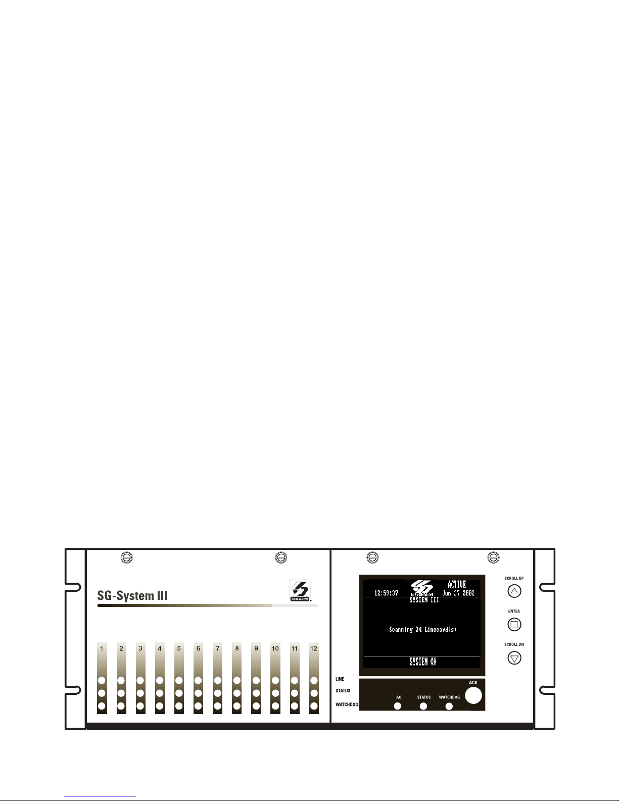
The System III is a multi-platform digital telephone receiver
intended for remote monitoring of commercial fire and burglary systems.
The System III can monitor up to 24 telephone lines; receive
and process alarm data in up to 64 pre-programmed formats (profiles) per line card.
The System III real time clock and calendar stamps all
received alarm data which are then transmitted to a central
station computer via TCP/IP or RS-232 port; transmitted
directly to a printer using the parallel printer port; and
viewed on the LCD of the front panel. System configuration
and phone line profiles can be programmed using a PC with
System III Console Software or locally using the scroll buttons and LCD. Each rack can house up to 12 DRL3 cards.
Each telephone line is monitored by a DRL3 line card.
1.1 System Overview
• Patented Caller Identification (Call Display) capability
• Patent pending AHS (Automatic Handshake selection)
• Patented virtual configurations
• Non-volatile RAM on each DRL3 line card for programming and event buffer
• Flash download for software upgrades for the DRL3
line cards and the CPM3
• DSP technology (patent pending)
• Up to 64 different options set (profiles per line card)
• Up to 8 different handshakes per profile
• Large, easy to read LCD (Liquid Crystal Display)
• All modules function individually to help ensure
uninterrupted operation during hardware or software upgrades
• All cards are Hot Swappable. Printed circuit cards
can be removed and replaced without removing
power from the system or compromising the system performance
• 24 lines maximum per redundant receiver
• 512-event memory buffer on each individual line card
• Real-time clock
• One parallel printer port, two serial RS-232 ports
and 10/100BaseT connection per rack
• Operator Acknowledge
• Programmable serial ports configuration
• Continuous verification of the computer-receiver
links with the 'heartbeat' function
• Fast transmission of multiple alarms to the computer
and printer to ensure operator's quick response
• Telephone Line supervision
• Rack mount in standard 19 inch rack
For UL listed installations use MLR2-CL, MLR2-CM,
IMRAK 1400 or other equivalent listed enclosure.
1.2 Approvals
1.2.1 Industry Approvals
The System III is listed under the following UL standards:
• UL 864 Control Units for Fire-Protective Signaling
Systems
• UL 1610 Central Station Burglar Alarm Units
This equipment should be installed in accordance
with the requirements of NFPA72, NFPA70, UL827
and the authority having jurisdiction.
1.2.2 UL Manual Mode
For UL manual mode, each event will activate the
internal buzzer to be acknowledged manually. Each
event will also be sent automatically to the connected printer.
For Central Station applications, the signaling performance of each DACT (Digital Alarm Communication
Transmitter) shall be manually tracked. Failure to
receive a signal from a DACT over 24 hour period
shall be handled as a trouble signal.
Figure 1-1, System III
1
1.3 Description (Hardware)
• Basic Configuration: The basic configuration consists of one 19" rack mounted chassis comprising
the following:
• BP3 Backplane provides interconnection of modules and communications interface
• CPM3 Module contains the CPU that controls all
communication to and from up to 24 line receiver
modules, printers, including 2 serial ports and an
Ethernet connection.
• PSU3 Power Supply Unit provides power to all
modules of the system.
• DRL3 Line Card: Each DRL3 line card monitors one
telephone line. Stores on the card up to 64 profiles
for data management including 8 different handshaking protocols. Each card has a 256-event
buffer, for short term retention of signals.
• DC/DC3 provides 5 V
the DRL3 line cards. A slot exists for a second DC/
DC3 voltage converter. In the event of a failure, the
redundant DC/DC3 can be removed/replaced without powering down the unit.
• PSC3 (Power Supply Controller) monitors the
states of the power and fan for each MLRF3.
• MLRF3: The metal rack of the System III that incorporates the LCD and BP3.
1.3.1 BP3 Backplane
The BP3 provides for interconnection of system
modules and racks; and provides communication
outputs as indicated in figure 1-6.
1.3.2 DC/DC-3 5V Power Converter
Each DC/DC3 converts 15VDC input from the PSU3
module and outputs the 5V
ules to function. A slot is provided for a second DC/
DC3 power supply to provide full redundancy for
DC power requirements. Power will remain ON if
5V
there are two DC/DC3 in the rack. The DC/DC3 is
also Hot Swappable if a working redundant DC/DC3
is in the same rack.
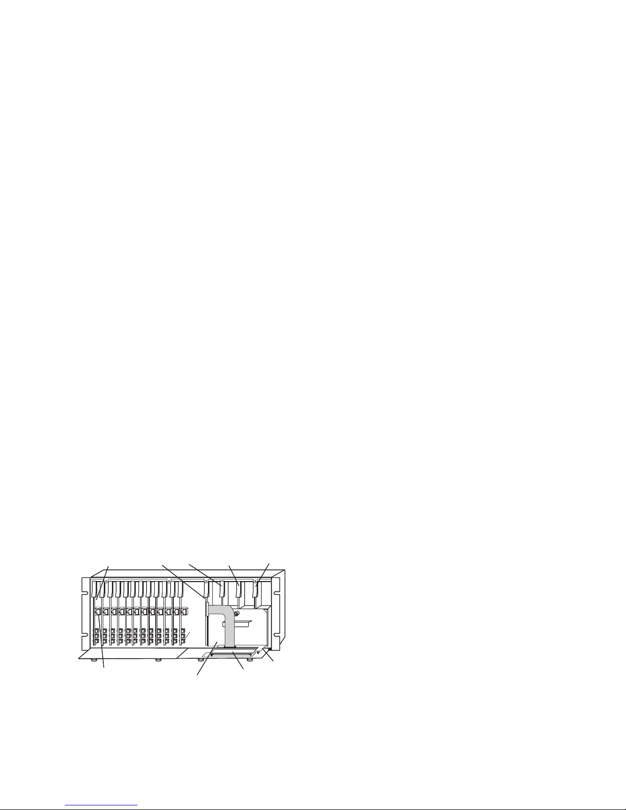
Fig ure 1-2
DRL3 Line Card
(12 cards per rack)
Line Card Debug Output
DC power output required for
DC required for all mod-
CPM3 PSC3 DC/DC3 B
PSU3
Fan (not shown)
located above PSU3
LCD
DC/DC3 A
UIB3
1.3.3 PSU3 Power Supply Unit
The PSU3 is the System III power supply. The
System III requires a 120VAC/60Hz input power
source. A power cord with a IEC connector is
required. The model System III CE requires a 240V
50Hz input power source.
NOTE: For UL installations use only 120VAC/60Hz to
power the SYSTEM III.
For UL installations use UL listed UPS Power Supply
for protective signaling systems and/or listed burglar alarm power supply, as applicable.
The model System III CE is not UL Listed.
Electrical Specifications:
System III
• Input voltage range: 120 V
AC
• Frequency: 60 Hz
• Input current: 2.5A max (RMS) @120 V
In 2-rack configurations a redundant PSU3 can be
inserted in the second shelf. In the event of a PSU3
failure, the redundant PSU3 automatically assumes
operation. These modules are Hot Swappable (can
be removed/replaced while the system is in operation) if a working redundant PSU3 is installed.
1.3.4 PSC3 Power Supply Controller
The PSC3 performs two functions. It provides the
high voltage required for backlighting to the LCD display. It also monitors the activity of the PSU3, DC/
DC3 power supplies and the power supply fan, and
reports their status to the CPM3 module.
1.3.5 CPM3 Central Processing Module
The CPM3 Central Processing Module collects system information and directs line card information to
the appropriate outputs. Along with it's built in scroll
buttons and large LCD message screen, the CPM3
features TCP/IP, parallel printer and two serial RS-232
ports for computer interface capability. The printer is
supervised for loss of power, off-line, paper out and
other trouble conditions. The communication link to
the computer through the RS-232 and TCP/IP port
can be monitored by the supervisory heartbeat test
transmissions.
1.3.6 DRL3 Line Card
The System III supports a maximum of 24 line cards.
Each DRL3 line card can monitor one telephone line
and act independently of the CPM3 module. Each
module is equipped with a 256-event non-volatile
memory to record events and corresponding telephone numbers. Calling source (Caller ID, ANI and
calling name) capability is built-in and telephone
numbers can be printed out, sent to automation and
stored in memory. Events and information stored in
memory may be printed at any time. Each line card
also features flash downloads through Ethernet or
serial port for fast software upgrades.
AC,
AC
2
The DRL3 receives ANI (Automatic Number Identification) and/or DNIS (Dialed Number Identification
Service) via the Telco connection. This information
allows the Sur-Gard expert format identification system to change options on the fly for each received
call. This eliminates dedicated line pool hardware.
The DNIS information is used in a look-up table,
which sets up virtual line pools to identify security
formats and extend account numbers. Standard
dialed number identification is supported up to 10
digits. Each dialed number would have formerly been
a line pool on conventional line cards.
1.3.7 BP3X Interface Module
(optional - one required per rack)
This 19” Rack mounted panel interfaces with the
System III Telco connector to provide 24 RJ-11 connectors for direct connection to telephone lines.
NOTE: On the BPX3 the B ports are the channels
used for two-way audio or back-up telephone line.
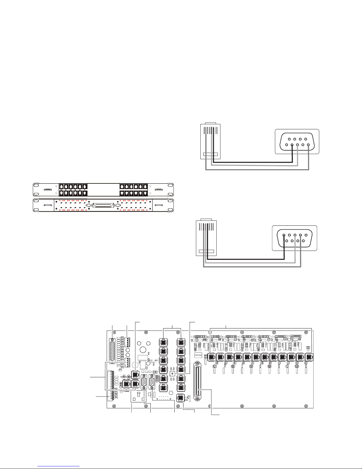
Figure 1-3 Front
A A
BP3X
B B
6 5 4 3 2 1
• Parallel Printer: A standard parallel printer output is located
on the back of the CPM3.
For UL Listed applications, the following UL listed printers
can be used with the System III:
- Sur-Gard CPU-1150 - DMP SCS-PTR
- Sur-Gard CPU DMP-206 - Seiko DPU-414
• Serial Printer
: A standard serial printer output is located on the
back of the MLRF3.
For UL Listed applications, the following UL listed printers can
be used with the System III: Seiko DPU-414
IMPORTANT: Do not use a printer cable that has only 1
common ground wire.
Figure 1-6, System III Wiring Diagram
* For Model System III CE:
- 240V
AC /50Hz
- System III CE is not UL Listed
**CAUTION: The ethernet
communication lines must be
connected first to an Approved
(acceptable to the local
authorities) type NID (Network
Interface Device) before leaving
the premises (e.g., UL
installations, UL60950 Listed
NID).
Connections for second
backplane
DB25
Parallel
Printer
Output
Not
Used
CPM3
Debug
Output
12 RJ-45
Connectors
Not Used
NOTE: Non-printable characters are replaced by a square
on the print out. Ensure that the printer is configured for
80 columns (System III only supports 80 columns).
• Connections for Redundant System III: Refer to Figure 1-7
System III Redundancy Wiring Diagram.
• CPM3 Debug Output: Connect the RJ-45 end of the debug
cable to the debug output jack.
Connect the female DB-9 connector to the serial port of a
computer (COM1 port - usually DB-9 male).
Figure 1-4 CPM3 Debug Cable
RJ45
1 2 3 4 5 6 7 8
Pin 2 to Pin 5
Pin 5 to Pin 3
Pin 6 to Pin 2
Back of DB9
• DRL3 Debug Output: Connect the RJ-45 end of the debug
cable to the debug output jack on the front of the line card.
Connect the female DB-9 connector to the serial port of a
computer (COM1 port - usually DB-9 male).
Figure 1-5 DRL3 Debug Cable
RJ45
1 2 3 4 5 6 7 8
Pin 3 to Pin 2
Pin 4 to Pin 3
Pin 5 to Pin 5
Back of DB9
• IEC Power Connector: Provides local power line connection
(cable is not supplied).
Shelf
Address
Switch
4
5
3
6
7
2
8
1
0
9
A
F
E
B
C
D
12 RJ-45
Connectors
Not Used
Note: All external
devices should be
mounted in the same
room as the receiver.
All circuits
are power
limited
976
8
54321
12345
689
7
See System III Supervised
UPS Connection Diagram for
details
Note: For UL Installations:
- AC input is 120V
- Do not connect to a receptacle
controlled by a switch.
AC / 60 Hz.
IEC Power
Connector
120Vac / 60 Hz*
2.5A
RS-232
Serial
Automation
Output
RS-232
Serial
Printer
Output
3
Ethernet**
Output
10/100 BaseT
25 Pair RJ-21 Supervised Telephone Lines
(Refer to Appendix C for pin out)
Note: Maintain 6.5mm (1/4") separation between
power limited and non-power limited circuits.
WARNING! To reduce the risk of electric shock the product is provided with a grounding type power supply IEC
recepticle. Connect product using an appropriate IEC
cable to a grounded recepticle.
• RS-232 Serial Automation Output: Provides serial connection to a local computer running automation software. A
straight through serial cable must be used.
• RS-232 Serial Printer Output: Provides serial connection to
a local computer or serial printer.
• 25 Pair Telco Connection: Connects directly to the local PBX
or to BP3X-3 (Refer to Appendix C for pinouts).
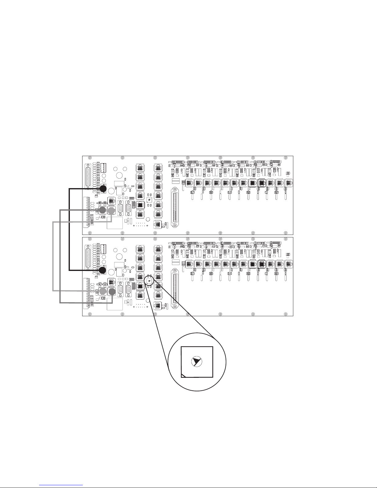
Figure 1-7, System III Redundancy Wiring Diagram
• Ethernet Output 10/100 BaseT: Traditional automation
communication is provided via port 1025 on the Ethernet
connection. This primary port is a Sur-Gard standard output
and provides Sur-Gard standard automation protocol output. All or a number of virtual receiver types can be mapped
to the Sur-Gard output.
CAUTION: The ethernet communication lines must
be connected first to an Approved (acceptable to
the local authorities) type NID (Network Interface
Device) before leaving the premises (e.g., UL
installations, UL60950 Listed NID).
All circuits are power limited
Use only the cables provided in the
System III Interconnect Pack. Failure
to do so may result in damage to the
unit. Using the provided RJ-45 patch
cables connect the Output of the
primary System III (shelf address 1)
to the Input of the redundant system
III (shelf address 2). Connect the
Output of the redundant System III to
the Input of the primary System III.
4
5
3
6
7
2
8
1
0
9
A
F
E
B
C
D
4
5
3
6
7
2
8
1
0
9
A
F
E
B
C
D
4
5
3
6
7
2
8
1
0
9
A
F
E
B
C
D
Use a small flat screw
driver to turn the shelf
address switch to 2 on
the second redundant
System III.
Shelf 1
Shelf 2
4
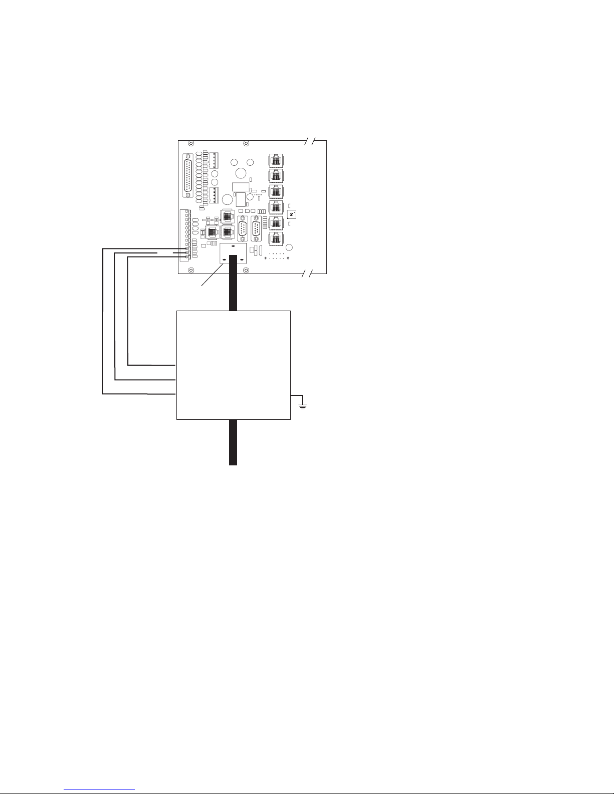
Figure 1-8, System III UPS Supervision Connection Diagram
SG-System III Backplane
12V , 25mA
DC
In2
In1
COM
For UL installations use
UL listed UPS
(uninterrupted power
4
5
3
6
7
2
8
1
0
9
A
F
E
B
C
D
supply) power supply for
protective-signaling
systems and/or listed
burglar alarm power
supply, as applicable.
IEC Power
Connector
For UL Installation of model SG-System III: UPS Output 120V /60Hz, 2.5A
For model System III CE (not UL Listed): UPS Output 240V 50Hz
AC Out
Note:
UPS connection is to
be made using dry
contact connections
provided by the UPS.
Common
UPS LOW BAT Normally Closed
UPS AC TROUBLE Normally Closed
AC In
For UL Installation of model SG-System III: UPS Output 120V /60Hz, 2.5A
For model System III CE (not UL Listed): UPS Output 240V 50Hz
UPS
EGND
WARNING:
To reduce the risk of electric shock the product is provided with
a grounding type power supply IEC receptacle. Connect product
using an appropriate IEC cable to a grounded receptacle.
AC
AC
AC
/
AC
/
5

1.4 Receiver Setup and Operation
DSC recommends testing the receiver before actual
installation. Becoming familiar with the connections
and setup of the unit on the workbench will make
final installation more straightforward.
The following items are required:
• IEC power supply cord
•One telephone line
• One or more dialer or digital control panel(s)
1. Unpack the components for the System III.
NOTE: Carefully unpack the receiver and inspect
for shipping damage. If there is any apparent damage, notify the carrier immediately.
2.Unscrew the front thumb screws and open the
front plates.
NOTE: Before inserting the CPM3 connect the ribbon cable from the UIB3 board. Before inserting
the PSC3 connect the LCD backlight.
3. Insert all the cards in the rack, in their appropriate
position (refer to figure 1-2). Connect the ribbon
cable of the front panel to the CPM3 before inserting it. Connect the backlight power connection to
the PSC3 then insert the PSC3.
4. Insert the PSU3 into the rack and fasten it properly.
5.Connect a telephone line to the proper line.
6. Connect the main power using a standard computer IEC cable (not supplied).
7. The LCD will power up and display internal troubles
(printer, computer, telephone line fault). The DRL3
that has the telephone line connected to it will have
its red LED off. If the LED is always on make sure the
telephone line is connected to the right port.
NOTE: Internal diagnostics may require more than
one minute during the power up sequence.
8.Send a signal from a control panel to the receiver.
The signal will be displayed on the LCD. Press the
[ACK] button to silence the buzzer and clear the
signal from the LCD.
1.5 Description (Operation)
1.5.1 Operation with Default Programming
Without any changes to the factory default programming, the receiver operates as indicated below:
• Answers incoming calls on the first ring
• Sends the following handshake order
1
2300 Hz
2
1400 Hz
3
Dual-tone
4
SIA FSK
5
ITI, Modem IIE/IIIa2
6
Modem II
• Receives all communication formats, except for 3/2,
3/1 checksum, SKFSK, 4/2 extended, and 4/2 checksum (see Option 95).
• The above formats can be manually selected
• Signals can be displayed on the debug output com-
puter as they are received. The signals are then sent
to the printer and computer connected to serial port
COM1 or to the 10/100BaseT connector. The default
event codes described in the DRL3 Library Decod-
ing and Event Codes Table will be used with the
Sur-Gard automation communication protocol to
send signals to the computer, if connected.
• If a computer is not connected press the [ACK]
button on the CPM3 to silence the buzzer and to
clear the alarm(s) from the LCD display.
1.5.2 Virtual Connectivity
Each receiver has one static IP address and a number
of associated ports. Internal socket programming
uses specific ports for expected tasks. The configuration management, done from the Console Software,
is located on port 1024. The System III Console software is provided for Windows 98/ME/NT/2000/XP,
which provides a graphical style menu for configuration management. Additional features are available
with the Console software including storage of virtual
receiver setups and configuration wizards.
NOTE: For Windows NT, user must be logged in as
Administrator or with administrator rights for
proper use of the Console Software.
1.5.3 Status Addressing
Line card status is reported via physical addressing.
Shelf and slot number are assigned automatically to
each line card. All device status information is in SurGard format. The reporting of status on this port,
automation output and printer will relate to physical
addressing.
1.5.4 Automation Input/Output (Port 1025)
Traditional automation communication is provided
via port 1025 on the Ethernet connection. This primary port is a Sur-Gard standard output and provides Sur-Gard standard automation output.
1.5.5 Compatibility
Central station automation software packages such as:
• MAS • DICE • SIMS II • GENESYS
• S.I.S. • IBS • MicroKey
support the System III Sur-Gard interface. Refer to
automation software specifications for compatibility.
NOTE: Automation connections are considered supplementary per UL864 Listing. Compatibility with the
automation software in a system used at a central
station is intended to be handled under a separate
UL1981 software and/or site certification evaluation.
1.5.6 Automation Protocols
The System III receiver sends a variety of protocols
to report signals to the central station computer via a
TCP/IP and/or RS-232 port. A complete list of protocols can be provided upon request.
1.5.7 Data Byte Protocol
The System III receiver uses a default configuration of
9600 Baud rate, 1-start bit, 8-data bits, 0-parity bits
and 1-stop bit structure, to transmit and receive signals
6

on the RS-232 port. This protocol can be programmed
on the receiver to enable different configurations.
1.5.8 Acknowledgment of the Signal
The System III receiver requires an acknowledgment
signal [ACK] (Hex 06) from the computer software
within 4 seconds for each message sent. Failure to
receive the [ACK] will result in 3 retransmissions of
the signal before indicating a communication failure.
During a communication failure the System III
receiver will cease transmitting except for the heartbeat. The same thing happens if the receiver receives
a [NAK] (Hex 15). In case of communication failure
with the computer, the System III receiver can store
up to 256 events per line card in the line card internal memory. Communication is resumed when the
first acknowledgment is received on the heartbeat;
all buffered information is then transmitted.
1.5.9 COM Responses
When the CPM3 sends an event to the computer, it
checks for 3 responses: ACK, NAK or Unknown/No
Response. An ACK tells the CPM3 the computer
automation got the event successfully. A NAK tells
the CPM3 the computer automation got the message but didn't understand it. The line card will
attempt to send the messages 25 times. If after 25
attempts it continually gets a NAK from the computer automation, the DRL3 will generate an internal
communication error. After 20 NAKs the CPM3 will
send an internal communication error event to the
printer. Any other response from the computer automation, including no response will cause the CPM3
to attempt to send the message again, up to 4
times. If after 4 attempts the CPM3 gets no
response or an unknown response, it will assume
nothing is connected and generate an alarm.
1.5.10 Automation Absent
When the computer is not responding to transmissions, the CPM3 will generate a 'SG-Serialx fail' or
'SG-TCP/IPx Fail' trouble. When a trouble occurs, the
CPM3 will continue to attempt to send a heartbeat
signal to the computer until it gets a response. The
System III receiver will make 4 attempts, then wait for
the next heartbeat period before making another 4
attempts. The typical heartbeat interval is 30 seconds.
Supervisory Heartbeat Signal Protocol (1)
00000
s
@
[DC4]
100000sssssssssss@ssss[DC4]
Receiver number (Real programmed number.
Never virtual).
Space Character.
Supervisory Signal.
Terminator, 14 Hex
This signal is used to supervise the communication
between the receiver and computer automation. It is
sent to the computer automation every 30 seconds
and is programmable from the receiver. The computer automation should acknowledge this signal
with an [ACK]. The CPM3 can be programmed to
send a heartbeat signal to the computer automation
once every 01-99 seconds to test the connection
between the CPM3 and the computer automation
(30 seconds is recommended). If a heartbeat fails to
get a response from the computer automation, the
CPM3 will immediately transmit the heartbeat again,
up to 4 attempts. The SG-System III, by default, will
output the automation signals via TCP/IP. If TCP/IP
fails it will switch to the Serial Automation output.
If the serial output fails, the CPM3 will switch to
manual mode, all signals will be displayed on the
LCD and will require a manual acknowledgement. To
re-establish connection with the TCP/IP a reset SG
fallback command must be generated from the Console software. If the line card buffers are full, the line
cards will stop answering calls.
1.5.11 System III SIA Internal Status Output
0
RR
LLL
0000
NYYZZ
[DC4]
0RRLLL[#0000|NYYZZZZ]
Protocol ID
Receiver number of the CPM3
Line card number, 000 signifies a
CPM3 Event.
System III account.
SIA Event
Terminator, 14 Hex
Refer to “CPM3 Internal Status Messages” on
page 35.
7
Section 2 - CPM3 Operating Modes
192.168.0.1
192.168.0.1
2.1 Contrast Adjust
To adjust the contrast press the Up and Enter buttons together to increase the contrast or press
Scroll Down and Enter together to decrease the contrast. This operation can be done at any time after
the power up sequence.
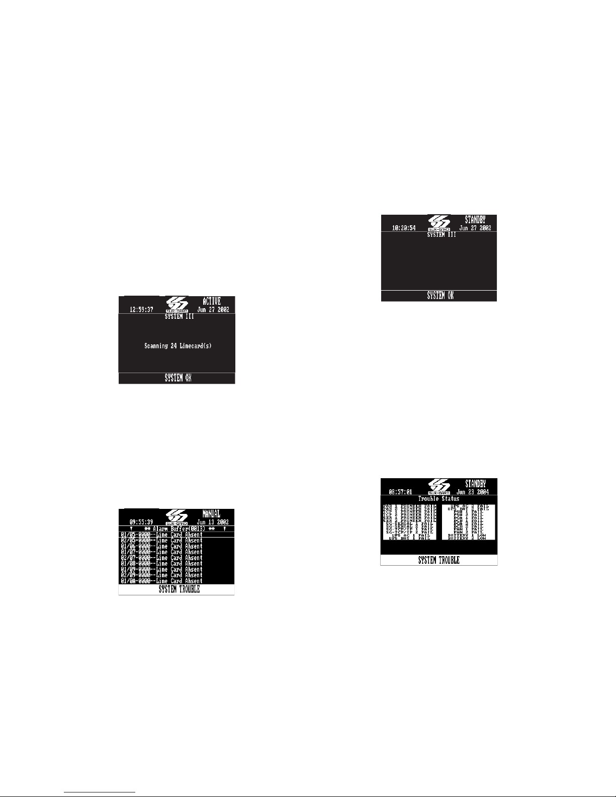
2.2 Active Mode
In active mode, the primary connection to the computer is via TCP/IP networking on the 10/100 BaseT
Ethernet connection for the automation computer. If
this fails, then the output will go via serial RS-232. A
command can then be sent through the System III
Console software to revert back to TCP/IP when the
connection is restored. The IP of the CPM3 is displayed on the screen.
Figure 2-1, Active Mode
192.168.0.1
2.3 Manual Mode
For manual mode, each event will activate the internal buzzer to be acknowledged manually. Each event
will be sent automatically to the connected printer
and displayed on the CPM3 LCD. Messages longer
than 80 characters will be displayed on two lines.
Once the signal is acknowledged, it will be cleared
from the screen.
Figure 2-2, Manual Mode
NOTE: The CPM3 will display a maximum of 5000
events which have not been acknowledged.
2.4 Standby Mode
When two CPM3s are present, one CPM3 will be in
active or manual mode, and the other CPM3 will be
in standby. If the active CPM3 fails, the standby unit
will automatically take over the control of the system. The IP of the CPM3 is displayed on the screen.
Figure 2-3, Standby Mode
192.168.0.1
2.5 System Trouble
When a trouble is present on the System III, the
message ‘SYSTEM TROUBLE’ will be displayed at the
bottom of the screen.
• To view which trouble is present, press the
SCROLL UP and SCROLL DN buttons simultaneously. (All signal must be acknowledged before
this is available.)
• To return to the main screen, press the SCROLL UP
and SCROLL DN buttons simultaneously, or wait
for timeout before this is available.
System Troubles are displayed as shown in Figure
2-4:
Figure 2-4, System Troubles
8
Section 3 - DRL3 Operating Modes
3.1 DRL3 Standby Mode
After start-up the line card enters the Standby mode
and monitors the telephone line and the CPM3.
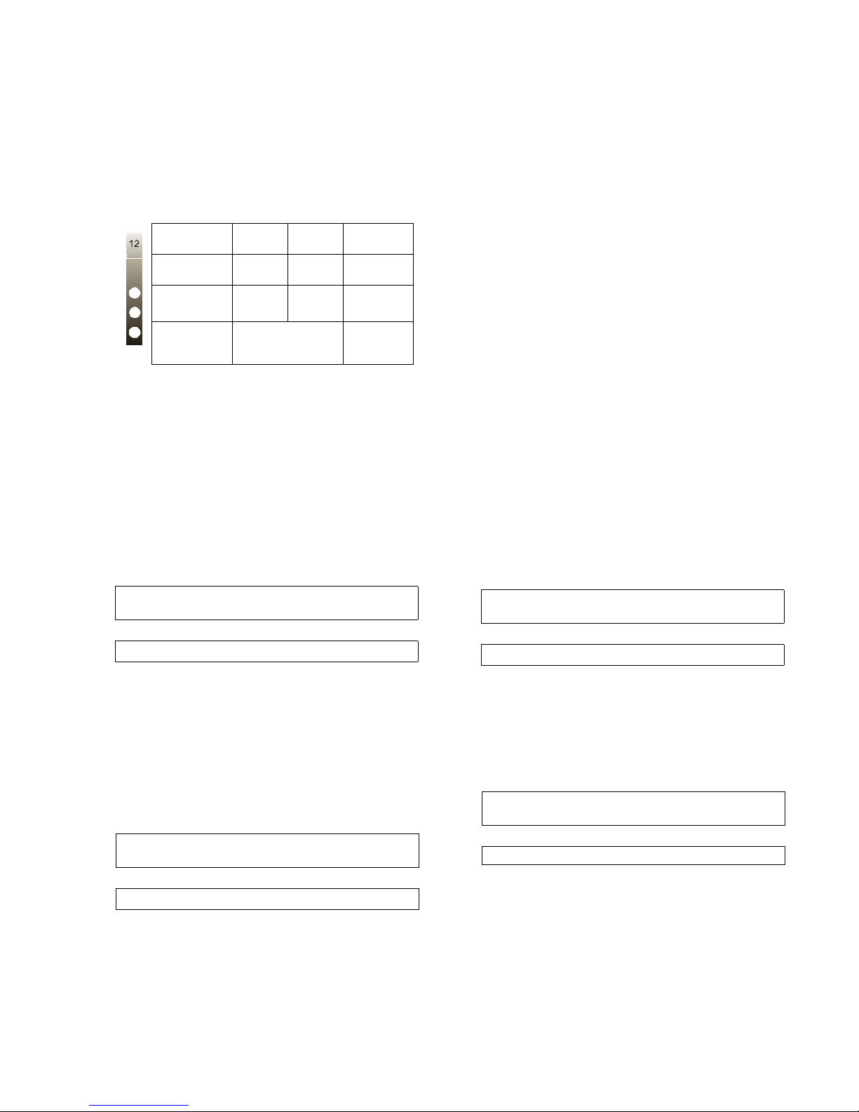
Depending on the system's status, the following conditions will be displayed for each line card:
LED ON OFF FLASH-
LINE
(Red)
STATUS
(Yellow)
WATC H-
DOG
(Blue)
Line
Fau lt
On-line Off-line
Line Card
not functional
Line
Normal
* The number of flashes on the yellow LED
indicates the following errors:
1. CPM absent
2. Line card clock not set
3. EBUS command to disable the line card
was sent.
4. Printer or computer buffer full.
5. Checksum failed when downloading
Flash ROM files.
3.2 Line Fault
The DRL3 verifies the telephone line voltage. The
'Line Fault' LED will come ON when the voltage drops
below 12V
Printer:
Jul 17 1998-08:08:28-SS/OO-SG-RR-LLL-0000PHONE LINE TROUBLE
Computer:
0RRLLL[#0000¦NLTSSOO][DC4]
A hexadecimal number from 01 to 0C representing
the slot number of the line card will be sent for each
'00' shown above.
A hexadecimal number from 01 to 02 representing
the shelf number of the line card will be sent for each
'SS' shown above.
When the line condition returns to normal, the 'Line
Fault' LED will be shut OFF. The following information
will be transmitted to the printer and computer:
Printer:
Jul 17 1998-08:08:35-SS/OO-SG-RR-LLL-0000PHONE LINE RESTORE
Computer:
0RRLLL[#0000¦NLRSSOO][DC4]
NOTE: Additional line fault operation if Backup
Line option is enabled. See Backup Line option
(Option 0E) for explanation.
DC.
ING
N/A
*Error
condition
Line Card
functional
3.3 CPM3 Error
If the DRL3 cannot detect the CPM3 polling, the
DRL3 will start buffering incoming calls. Up to 512
alarm messages for the printer and computer will be
retained in the DRL3 event buffer. When the event
buffer is full, the line card will stop answering the
calls and the status LED will begin flashing. When the
CPM3 Error condition is corrected, the alarm messages in the event buffer will be transmitted to the
CPM3 with the corresponding time/date the alarm
has been received.
3.4 Data Reception
During data reception, the yellow STATUS LED will
turn on. The DRL3 decodes all information received
and stores the information in its Event Buffer. When a
valid signal is received, the DRL3 sends a kiss-off signal and transmits the decoded alarm signal to the
computer and to the printer through the CPM3. The
DRL3 will send each message it receives to the
printer for review by the system operator. Two messages may be sent to the printer to indicate reception problems: the 'Fault Data' (Invalid Report) and
'Fault Call' (Communication Fail).
3.4.1 Fault Data Message
When this problem is encountered, the following information is transmitted to the printer and the computer:
Printer:
Jun 25 1998-11:18:07-SS/OO-SG-12-234-0000INVALID REPORT
Computer:
012234[#0000¦NYNSSOO][DC4]
This output for account code '0000' indicates that
data has been received, but is not valid (for example,
there are unmatched rounds or incorrect parity).
3.4.2 Fault Call Message
When this problem is encountered, the following information is transmitted to the printer and the computer:
Printer:
Jun 25 1998-11:18:07-SS/OO-SG-12-234-0000COMMUNICATION FAIL
Computer:
012234[#0000¦NYCSSOO] [DC4]
This output indicates that a call was received, but no
data was detected. The call may have been a wrong
number, or the calling control panel was unable to
connect with the receiver's handshakes.
Computer message NACKed 25 consecutive times.
Printer message: Internal Comm. Error
Computer signal: RRLLL[#0000¦NRTSSOO][DC4]
9
Section 4 - Programming/Operation
4.1 Introduction
The System III can be programmed manually using
the front panel; from a local computer using the
Debug Output located on each line card behind the
front panel; or remotely using the TCP/IP network
and System III Console software. The Debug output
is intended as a testing and troubleshooting tool.
Manual programming allows the user to program all
of the System III options for remote and local operation. Manual programming does not support the
grouping of line cards into hunt groups or line pools.
4.2 System III Console Software
The System III Console software is intended to be
the primary method of programming the system,
refer to the System III Console User Manual for
details.
4.3 Debug Programming
The debug output is another method of accessing
the line card's programmed options and diagnostics
features. A debug cable is required to connect by
serial communication from the line card to a standard PC running Windows 95 or higher software.
NOTE: Debug programming only affects options in
profile “0”.
ALL PROGRAMMING WITH THE DEBUG SETUP IS
LOST WHEN THE SYSTEM IS POWERED DOWN OR
WHEN LINE CARDS ARE REBOOTED OR REMOVED
FROM THE RACK.
4.3.1 Debug Cable Connectivity
• Connect the RJ-45 end of the debug cable to the
debug jack on the front of the line card.
• Connect the female DB-9 connector to the serial
port of a computer.
4.3.2 Debug Software Setup
• Using Windows 95 or higher, point and click on
the button.
•Then select Programs Accessories Commu-
nications HyperTerminal. Once in the Hyper-
Terminal window, point and click on the
'Hypertrm.exe' icon.
• A connection description window should appear. A
prompt should appear on the 'Name' category.
Type a name. Point and click on the 'OK' button.
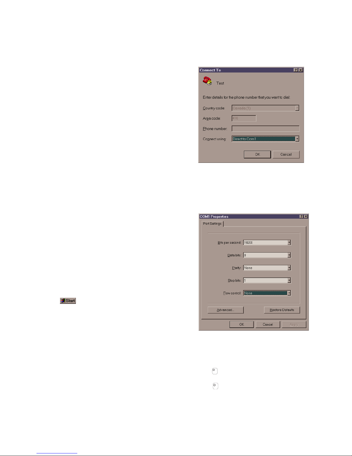
• A phone number window should appear. Choose
the direct to COM port required for connection
and point and click on 'OK'.
Fig ure 4-1
• The COMx properties windows should appear. The
configuration should be:
Bits per second:
Data bits:
Parity:
Stop bits:
Flow control:
Fig ure 4-2
• Click on the 'OK' button after setting the configuration.
• The HyperTerminal window should appear. Press
any key. The debug menu will be displayed.
Keyboard Commands
• The key will initiate the download of a file to the
line card.
• The key will enable the user to dump the current programmed options of the line card or set an
option to a particular value.
19200
8
None
1
None
10
4.3.3 Downloading Steps
1. Press the key to initiate downloading of the
binary file. The HyperTerminal will display:
Ready to download.
CCCC
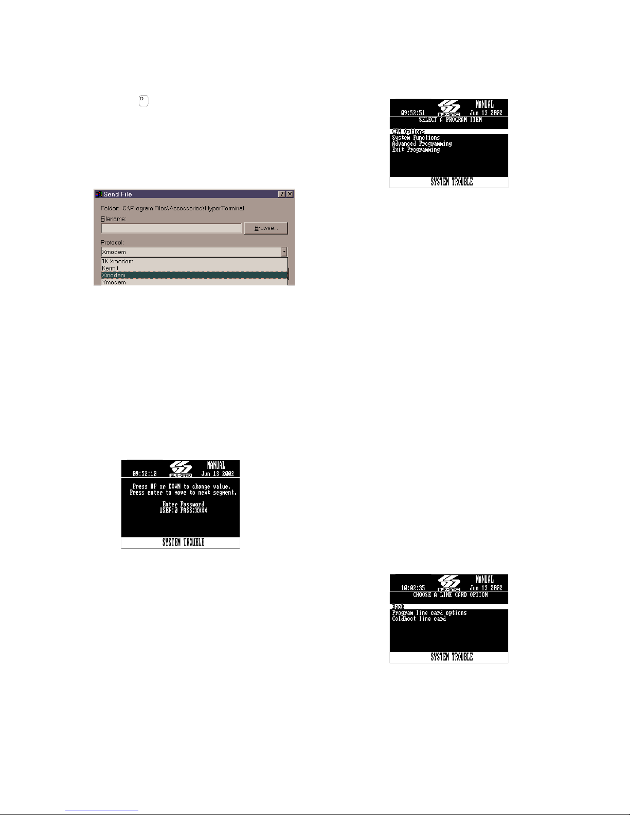
2. Point and click on 'Transfer' on the HyperTerminal
menu and access the 'Send File' category. The 'Send
File' window should appear.
Fig ure 4-3
3. Change the protocol to 'X-modem' and place the
correct path and file name of the binary file to be
downloaded.
4. Point and click on the [Send] button and the downloading status window should appear. The line card
will restart automatically after a successful download.
4.4 Manual Programming
The user interface consists of 3 buttons: the
Scroll Up button, the Scroll Down button, and the
Enter button. These buttons are used to access the
programming of the line cards and the CPM3, and to
view alarm and trouble messages in manual mode.
They are located on the right side of the screen.
Fig ure 4-4
The Configuration mode allows programming of the
various features and options available on the
System III. To enter the Configuration mode, press
the [Enter] button; the following screen will be displayed.
Enter the Master Access Code using the buttons; the
default Master Access Code is "CAFE" to change the
default Master Access Code.
When the access code is entered, the screen will display the Configuration Menu.
Figure 4-5, Configuration Menu
CPM Options allow the user to customize the operation of the system TCP/IP addressing, Passwords,
COM settings and other system functions are programmable here. Refer to the description of all CPM
options and their default settings.
4.4.1 Advanced Programming
The advanced programming menu allows the user to
change the options of a specific profile and line card.
The CPM3 will prompt the user to enter the line card
number, the profile number, and the option number.
When all the information is entered (the line card number, the profile number, and the option number), the
CPM3 will move to the option value segment and display
the current value of the option. The user can change the
value by pressing the up or down key. After the changing
the value, the CPM3 will display the following:
Line card Menu
0 Go to next Line card number
1 Go to next profile number
2 Go to next option number
3Save
The user can change multiple profiles and options per
line card. After all the modifications to options and profile are made, the user must Save in order for the
changes to take effect for each line card.
To exit from the menu, the user must press the Scroll Up
and Scroll Down keys simultaneously.
NOTE: The line card will need to be reset in order for
the options to take effect.
Programming Line Card Options:
• Cold boot Line Card
Resets the selected line card to the factory
defaults. This will also clear all the internal buffers.
Figure 4-6, Advanced Programming Menu
11
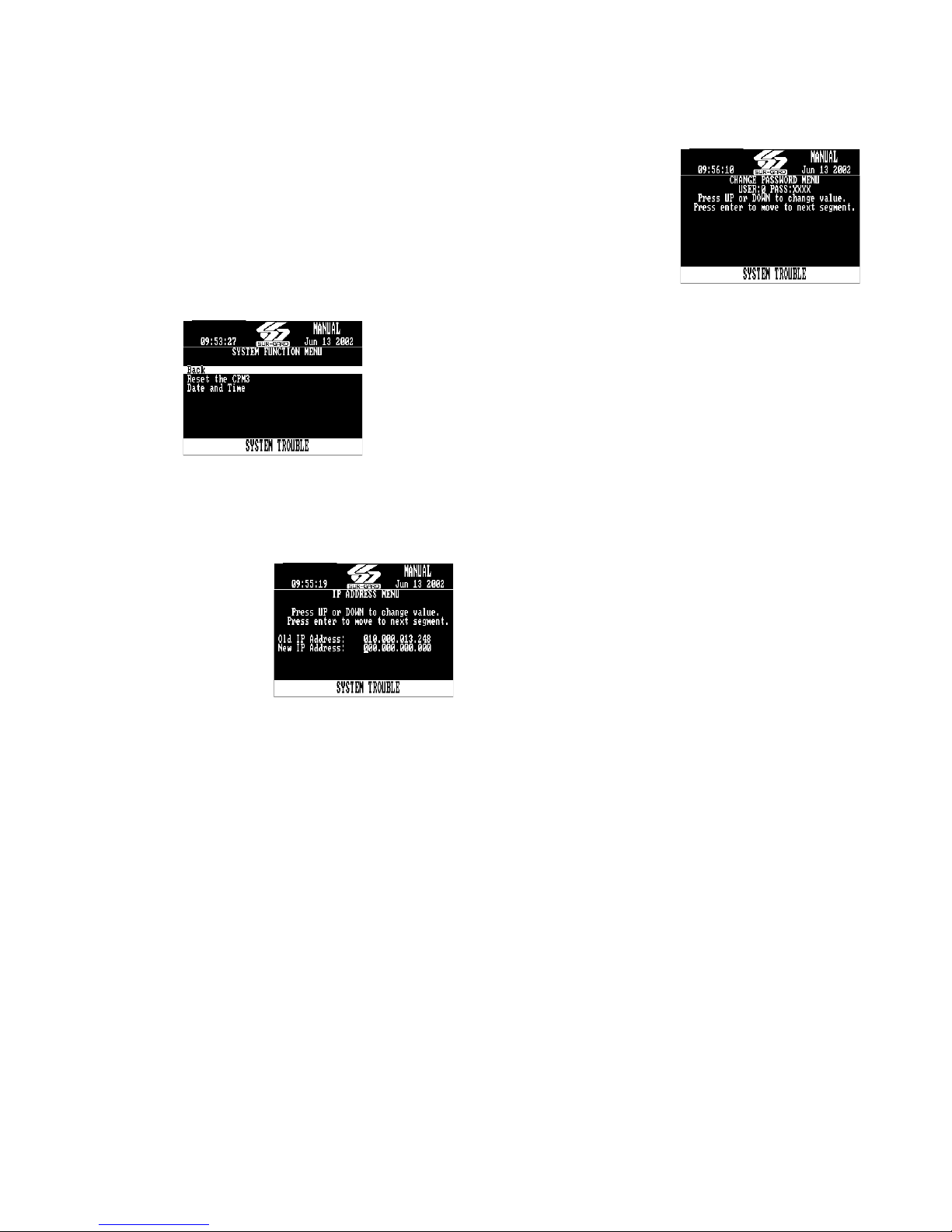
4.4.2 System functions
• Reset the CPM3
Restarts the CPM3. This is required to make the
changes to some options effective. For example,
the IP address.
•Date and Time
To set the date and time of the System III. This can
also be done from the Console software.
Figure 4-7. System Function Menu
Advanced Programming allows the user to customize line card profiles.
4.5 CPM3 Options
Option [01]: IP Address - Default [10.0.7.100]
Enter the IP Address of
the CPM3. Ensure that
the IP address programmed is unique to
the CPM3.
Option [02]: Subnet Mask
Address Default [255.255.0.0]
Enter the Subnet Mask
Address of the CPM3.
Option [03]:
Enter the Gateway Address of the CPM3 if required.
Option [04]: Auto Update Time & Date - Default [0]
This option allows the automation to update the SGCPM3’s time via the TCP/IP port. When enabled should
the CPM3 fail to get the time & date within 24 hours
period (started after the last update is received), it will
generate a status message to the printer and automation, following the internal trouble protocol. The Trouble
status on the CPM3 will not be affected. The SG-System
III Console time update function must be disabled when
using this feature or there is possibility that the CPM3
will not remain synchronized with the automation PC.
Printer message: "Time&Date Update Fail"
Automation message: 0RRLLL[#0000¦NRU0000]
Option [05]: Contrast Adjust - Default N/A
Allows the contrast of the message display screen to be
adjusted. Press the up or down button to adjust. The
contrast can also be adjusted from the main screen by
holding the up and enter buttons simultaneously to
increase the level, or by holding the enter and down buttons simultaneously to decrease the level.
Gateway Address - Default [0.0.0.0]
Option [06]: Password Menu - Default [CAFE]
Allows the System III
users and passwords to
be erased or changed.
Sixteen users with 4digit passwords are
available for use on the
System III. User 0 is the
Master user, and users 1
through F may be
assigned to individual
operators. The Master
user will provide access to all menus, while the operators
will not have access to the CPM3 settings. To erase a user,
program the password for that user to ‘FFFF’.
NOTE: User “0” cannot be erased.
Option [07]: COM1 Baud Rate - Default [9600]
Determines the baud rate at which the CPM3 will communicate to the automation software via serial port 1.
2400 9600
4800 19200
Option [08]: COM1 Data Bits - Default [8]
Determines the number of data bits used to communicate to the Automation Software connected on the serial
port 1. Choose a number from 7 through 9 to indicate 7,
8, or 9 data bits.
Option [09]: Parity - Default [0]
Determines the parity of the serial port 1.
0: no parity (default)
1: odd parity
2: even parity
NOTE: The number of stop bits can not be changed
and will always be 2.
Option [0A]: COM2 Format - Default [0]
This option affects how the COM2 Serial Port is supervised and how the data is formatted.
To disable the option set to [0].
To enable the printer messages to be outputted to a
serial printer via the COM2 set to [1].
To enable the printer messages to be outputted to a
computer via the COM2 port set to [2].
To enable SCADA interface through the COM2 set [3].
This setting is for FUTURE USE.
Option [0B]: COM2 Baud Rate - Default [9600]
Determines the baud rate at which the CPM3 will communicate to the Serial Printer connected on the serial
port 2:
2400 9600
4800 19200
OOption [0C]: COM2 Data Bits - Default [8]
Determines the number of data bits used to communicate to the Automation Software connected on the serial
port 2. Choose a number from 7 through 9 to indicate 7,
8, or 9 data bits.
Option [0D]: COM2 Parity - Default [0]
Determines the parity of the serial port 2.
0: no parity (default)
1: odd parity
2: even parity
NOTE: The number of stop bits can not be changed
and will always be 2.
12

Option [0E]: TCP GUI - Default N/A (Future Use)
Option [0F]: B32 Headers - Default [00]
Compatible with MAS B32 Automation Software through
TCP/IP. To enable, change to [01].
Option [10]: Input RRLLL Digits - Default [5]
Indicates the number of expected digits in the computer
message header from the line card. This must be the
same as Option [02] of the line cards +2.
Option [11]: Output RRLLL Digits - Default [5]
Indicates the number of digits the CPM3 will send in the
header to the automation output. This should be left as 5
unless the automation software does not support the
MLR2000 or System III output protocol.
NOTE: Ensure that option [02] in the DRL3 line cards
is programmed to match this entry. For example, if
CPM3 option [0F] is programmed with [04], then DRL3
option [02] must be set to, [02].
Option [12]: Heartbeat Timer - Default [30]
Determines at what time interval, in seconds, the heartbeat transmission will be sent to COM1 and TCP/IP port
1025. The heartbeat transmission is used to ensure that
communications through COM1 and TCP/IP are functioning normally. Enter a decimal number from 01
through 99 to determine the time interval between
heartbeat transmissions. Program this option as "00" to
disable the heartbeat transmission.
Option [13]: Mute Buzzer - Default [OFF] (Disabled)
A tone will sound when the System III receives an alarm
and is unable to forward the alarm message to COM1 or
TCP/IP. The tone may be silenced with this option. If
enabled, the buzzer will not sound when an alarm is
received and cannot be forwarded to COM1.
Option [14]: Receiver Number - Default [01]
The receiver number is used to identify the receiver
when communicating to the TCP/IP Automation, COM1
and the printer. To change the receiver number, enter a
new receiver number using the hexadecimal numbers
"01" to "FE".
Option [15]: Printer Test - Default [Off]
When this option is enabled, a test signal will be sent to
the printer at 05:00 and 17:00 hrs. This option is set to
"0" (OFF) by default.
Printer message:
26 Nov 2003 16:41:25 - 26 Nov 2003-16:41:25-00/00SG -01-000-0000--Printer Test Message
Option [16]: Mask PSU 1- Default [Off]
Some installation may not have the full System III configuration, Option 14 through 1E are used to enable or disable the supervision of the selected components. To not
report the trouble, turn the appropriate option ON.
NOTE: PSU 1 is the PSU3 installed in shelf 1
Option [17]:
NOTE: PSU 2 is the PSU3 installed in shelf 2
Option [18]:
DC A is the Right DC/DC3 located on the same shelf as
the CPM3 being programmed
Option [19]:
DC B is the Left DC/DC3 located on the same shelf as
the CPM3 being programmed.
Mask PSU 2- Default [On]
Mask DC A - Default [Off]
Mask DC B- Default [On]
Option [1A]: Mask DC A2 - Default [On]
DC A2 is the Right DC/DC3 located on the other shelf
from the CPM3 being programmed.
Option [1B]: Mask DC B2- Default [On]
DC B is the Left DC/DC3 located on other shelf from the
CPM3 being programmed.
Option [1C]:
DC/DCB Shelf 1 trouble mask. If set, DC/DCB Shelf 1
trouble conditions are not reported
Option [1D]:
DC/DCB Shelf 2 trouble mask. If set, DC/DCB Shelf 2
trouble conditions are not reported.
Option [1E]:
Fan Shelf 1 trouble mask. If set, Fan Shelf 1 trouble conditions are not reported.
Option [1F]:
Fan Shelf 2 trouble mask. If set, Fan Shelf 2 trouble conditions are not reported.
Option [20]:
UPS AC Shelf 1 trouble mask. If set, UPS AC Shelf 1 trouble conditions are not reported.
Option [21]:
UPS Battery Shelf 1 trouble mask. If set, UPS Battery
Shelf 1 trouble conditions are not reported.
Option [22]:
UPS AC Shelf 2 trouble mask. If set, UPS AC Shelf 2 trouble conditions are not reported.
Option [23]: Mask UPS BAT 2 - Default [On]
UPS Battery Shelf 2 trouble mask. If set, UPS Battery
Shelf 2 trouble conditions are not reported.
Option [24]: Mask SG TCP 1 – Default [Off]
SG TCP Shelf 1 trouble mask. If set, SG TCP shelf 1 trouble conditions are not reported.
Option [25]: Mask SG Serial 1 – Default [Off]
SG Serial Automation Shelf 1 trouble mask. If set SG
Serial automation shelf 1 trouble conditions are not
reported.
Option [26]: Mask SG TCP 2 – Default [On]
SG TCP Shelf 2 trouble mask. If set, SG TCP shelf 2 trouble conditions are not reported.
Option [27]: Mask SG Serial 2 – Default [On]
SG Serial Automation Shelf 2 trouble mask. If set, SG
Serial automation shelf 2 trouble conditions are not
reported.
Option [28]: Mask TCP 1 Printer - Default [Off]
SG TCP Printer Shelf 1 trouble mask. If set, SG TCP
Printer shelf 1 trouble conditions are not reported.
Option [29]: Mask Parallel 1 Printer - Default [Off]
SG Parallel Printer shelf 1 trouble mask. If set, SG Parallel
Printer shelf 1 trouble conditions are not reported.
Option [2A]:Mask Serial 1 Printer - Default [Off]
SG Serial printer shelf 1 trouble mask. If set, SG Serial
Printer Shelf 1 trouble conditions are not reported.
Option [2B]: Mask TCP 2 Printer - Default [On]
SG TCP Printer Shelf 2 trouble mask. If set, SG TCP
Printer Shelf 2 trouble conditions are not reported.
13
Mask Low Battery 1 - Default [On]
Mask Low Battery 2 - Default [On]
Mask Fan 1 Fail - Default [Off]
Mask Fan 2 Fail - Default [On]
Mask UPS AC 1 - Default [On]
Mask UPS BAT 1 - Default [On]
Mask UPS AC 2 - Default [On]

Option [2C]: Mask Parallel 2 Printer - Default [On]
SG Parallel Printer shelf 2 trouble mask. If set, SG Parallel
Printer Shelf 2 trouble conditions are not reported.
Option [2D]: Mask Serial 2 Printer - Default [Off]
SG Serial Printer Shelf 2 trouble mask. If set, SG Serial
Printer Shelf 2 trouble conditions are not reported.
Option [2E]: Number of Line Cards- Default [12]
Option [1F] is used to set the number of line cards
polled by the CPM3. Enter a number from 01 to 24 to
indicate how many line cards are to be polled by the
CPM3.
Option [2F]:
The TCP/IP connection is the primary output of the System III for automation computer alarms. It is estimated
that sockets may appear and disappear regularly as processes are terminated and reconstituted. After 5 seconds of socket loss, a socket loss is declared and
automation output is shifted to the next connection
level, which is the serial automation output connection.
First configuration: LOOP (0)
If both outputs are present, the CPM3 will send to the
TCP/IP until it fails, proceed to the serial until it fails, proceed back to the TCP/IP until it fails ... and so on. See
Automation out flow diagram 1.
Second configuration: FALL BACK (1)
If both outputs are present, the CPM3 will send to the
TCP/IP until it fails, proceed to the serial until it fails, and
will keep trying on the serial continuously, or until the
reset fallback command is generated from the console,
in which case it would go back to try the TCP/IP connection. See Automation out flow diagram 2.
Third Configuration: ALL (2)
The CPM3 will always send to all connected outputs. If
at least one output replies with a ACK, then the alarm is
considered as transmitted regardless if the other output
acknowledged it or not. This setting is NOT recommended. See Automation out flow diagram 3.
Fourth Configuration: IP Fall Back Mode (3)
The CPM3 A will send through its TCP/IP output until it
fails. If it fails the CPM3 B will sent through its TCP/IP
output. If it fails the CPM3 A will send the signals
through its serial output. If that fails the CPM3 B will
output through its serial output. See Automation out
flow diagram 4.
Fifth Configuration: Automatic SG-Fall Back (4)
This mode is similar to Fall Back except that when the
TCP/IP connection is restored the CPM3 will return to the
TCP/IP port to send events. This eliminates the need for
the Reset SG Fallback from the SG-System III Console.
Automation Mode - Default [1] (Fall Back)
Option [30]:
The printer outputs can be configured in a similar
approach as the automation outputs except that the
FALLBACK (1) option is not available.
Default Configuration: ALL (2)
NOTE: Order of sequence is TCP, Parallel and finally Serial.
DSC does NOT recommend changing the default setting.
Option [31]:
Determines the acknowledge wait time, in tenths of a
second, to be used for automation outputs before the
CPM3 will try again if no response is received within this
interval.
Enter a decimal number from 40 to 99 for 4.0 seconds
to 9.9 seconds.
Option [32] Date Format – Default [0]
Selects the format used to represent date for printer output. Format [1] represents US format is
MM/DD/YY . Format [0] International format is DD/MM/
YY.
Option [33] Protocol ID – Default [0]
When this option is programmed as ‘0’ the CPM3 will
output its internal messages in the following format:
0RRLLL[#AAAA|Nxxyy]
When this option is programmed as ‘S’ the CPM3 will
output its internal messages in the following format:
SRRLLL[#AAAA|Nxxyy]
S,0 (zero): protocol number
RR: Receiver number
LLL: Line number
AAAA: Account code, always 0000
Nxxyy: SIA event
Option [34] Time Correct – Default [000]
The CPM3 will synchronize its time with the SG-System
III console application PC. However in some
situations it may be desirable to automatically correct
the time of the CPM3. The CPM3 will update its time
once an hour. Valid values are -590 to +590;
value represents time in tenths of a second (i.e. 243
means 24.3 seconds).
Option [35] Output Config – Default [Local] (Future Use)
Option [36] CIS Enable – Default [0] (Future Use)
Enable the CIS protocol for automation outputs.
Option [37] RBUS HighSpeed – Default [1]
Sets the speed of the communication from the CPM3 to
the to the DRL3s.
NOTE: The option in the DRL3 must be set to the
same speed in order for communication to work. All
units must have the same speed. Once changed the
unit must be reset for the option to take affect.
Printer Mode- Default [2]
ACK Wait - Default [40]
14
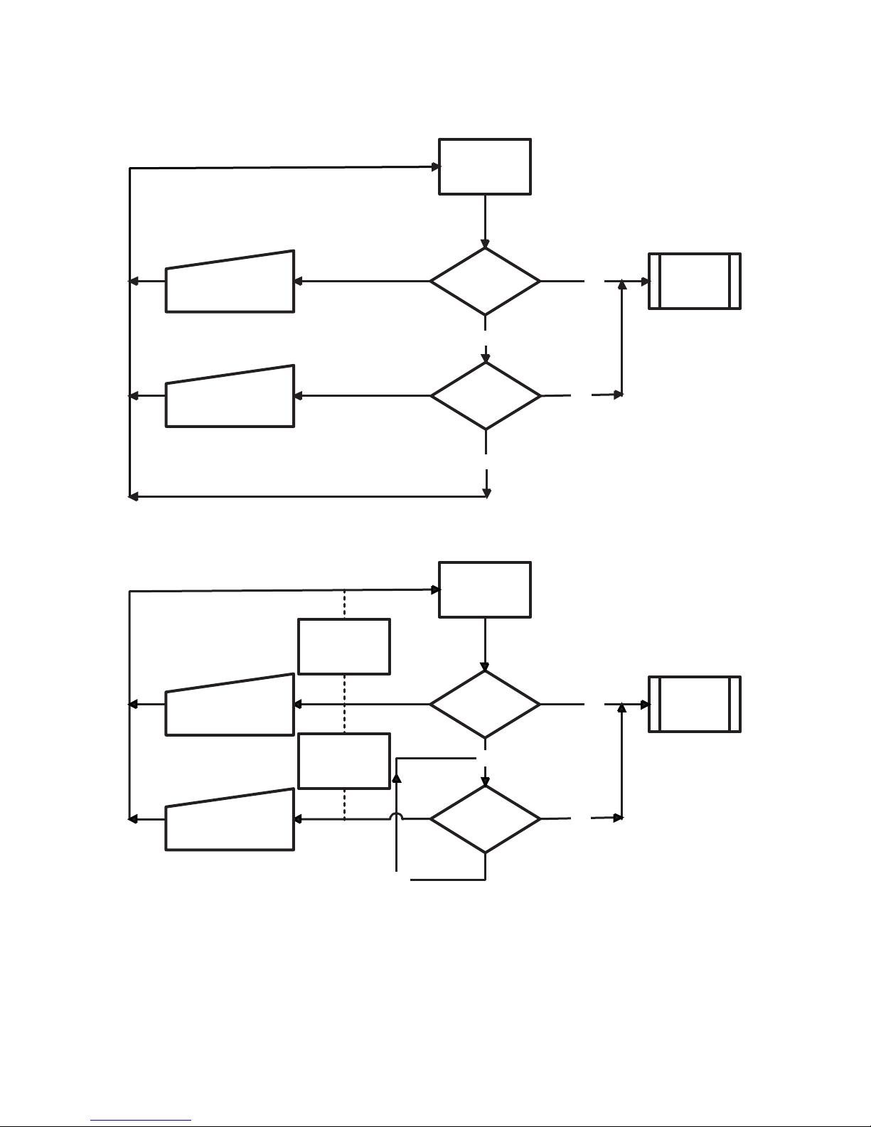
Flow Diagram for Automation LOOP Mode (0)
Power Up/Restart
Manual Re-start from
Console (Reset Fallback)
Manual Re-start from
Console (Reset Fallback)
Flow Diagram for Automation FALL BACK Mode (1)
Automatic Fall
Back mode (4)
CPM3 (A)
Ethernet Port
Active?
No
CPM3 (A) Serial
Port Active?
No
Power Up/Restart
Yes
Yes
Poll
Automation
Manual Re-start from
Console (Reset Fallback)
Manual Re-start from
Console (Reset Fallback)
Automatic Fall
Back mode (4)
No
CPM3 (A)
Ethernet Port
Active?
CPM3 (A) Serial
Port Active?
15
NoNo
Yes
Yes
Poll
Automation
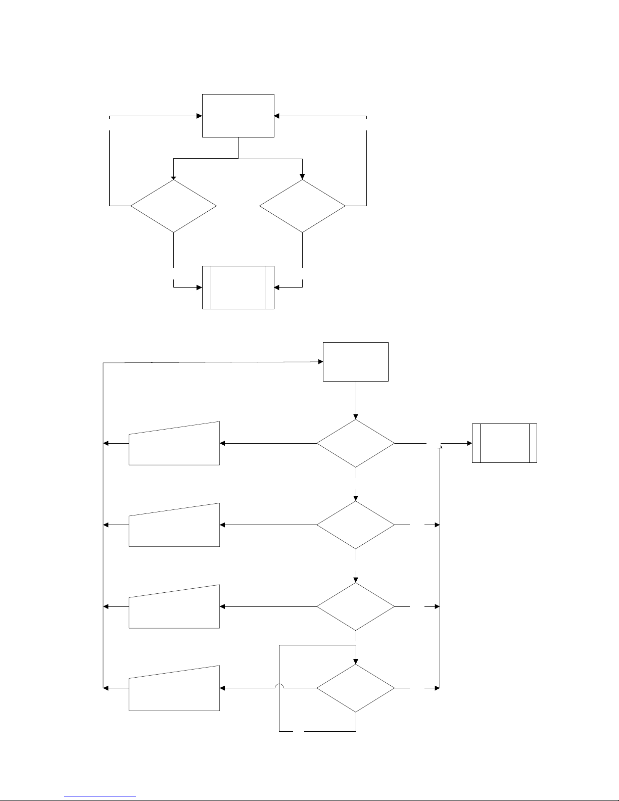
Flow Diagram for Automation ALL Mode (2)
Power Up/Restart
No No
CPM3 (A) Serial
Port Active?
Poll
Automation
Flow Diagram for Automation IP FALL BACK Mode (3)
Manual Re-start from
Console (Reset Fallback)
CPM3 (A)
Ethernet Port
Active?
YesYes
Power Up/Restart
CPM3 (A)
Ethernet Port
Active?
No
Yes
Poll
Automation
Manual Re-start from
Console (Reset Fallback)
Manual Re-start from
Console (Reset Fallback)
Manual Re-start from
Console (Reset Fallback)
No
16
CPM3 (B)
Ethernet Port
Active?
No
CPM3 (A) Serial
Port Active?
No
CPM3 (B) Serial
Port Active?
Yes
Yes
Yes
Section 5 - Advanced Programming
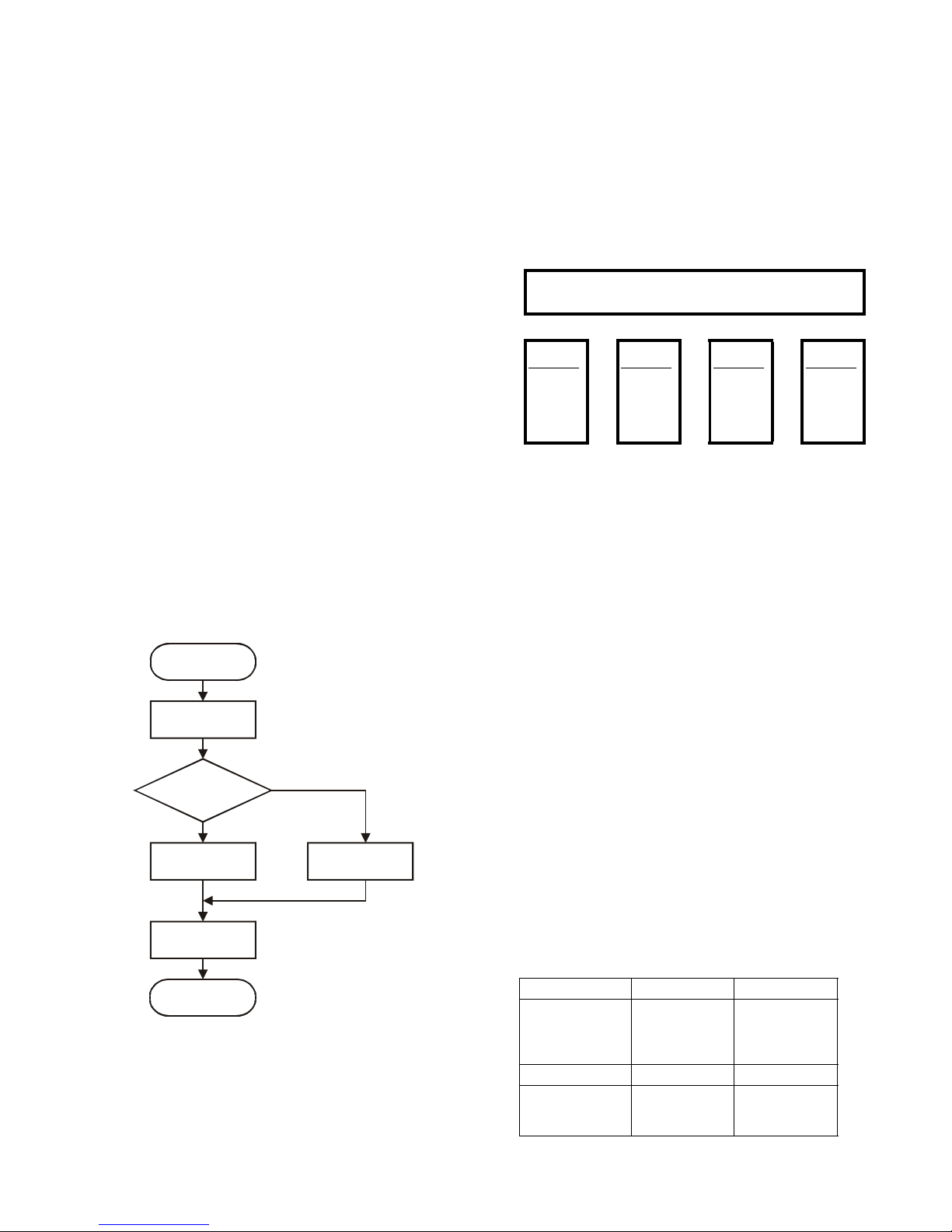
5.1 Profiles Introduction
The DRL3 'virtual receiver' will load unique 'profiles' in
order to effectively communicate with control panels. A profile is a set of pre-programmed line card
options unique for a particular DNIS number. The
'DNIS' will point to a particular profile, which will then
be loaded into the line card before the first handshake is sent. It is essential that the correct option
be programmed for a profile in order to correctly
communicate with the control panel. Each 'virtual
receiver' can have a maximum of 64 profiles. To
change the options for a particular profile, the System III Console software is provided. This software
will allow the user/operator to edit the profiles.
NOTE:DNIS (Dialled Number Identification Service).
This number represents the dialled number, or the
number being called. ANI: (Automatic Number
Identification). This number represents the source
of a call and allows the system to determine the
handshake protocol. Caller ID: This number identifies the source of a call. For the purpose of this document, Caller ID and ANI will be referred to as
Caller ID, but both can not be used at the same
time. Contact your provider to determine which
service is available.
DNIS or Caller ID can be used for profile selection.
Line Cards Identification Number Handling:
Figure 5-1, Call Processing Flowchart
Receive DNIS
or Caller ID
Send string to
Lookup Table
Corresponding
Profile?
YES
Point to Profile #
Use Options
from Profile
Done
Each profile is made up of Static Options and Dynamic
Options. The static options are the same for all profiles, but the dynamic options can be programmed
specifically per hunt groups, panel type, etc.
No
Use Profile 0
By receiving the DNIS or Caller ID, the appropriate
profile can be selected through a look-up table
"stored" on the line card.
Profile
0
Profile
1
Profile
2
(Default)
00
Static Options - identical for all profiles
2F
30
Dynamic
Options
30 Dynamic
Options
30 Dynamic
Options
unique
for each
profile
AF
AF AF AF
Profile 0 is the default. When no Caller ID or unknown
DNIS is received, or when the received number does
not point to a profile, the default will be used.
Profiles are used to reduce on-line time, and for specific customers or panel/format types, one can have
a profile with certain handshakes sent first. Also,
some formats require certain options, and this can
be pre-defined as well.
Profiles allow for a more customized system. Rather
than having a line card (or a receiver itself) devoted to
certain customers, the System III can "handle" any format at any time through the use of profiles. Each line
card holds its own look-up table that can be shared
through line pools, or shared within the entire receiver.
Two types of tables are available, but only one type can
be chosen. The first type, which consists of 10 000
entries, is used strictly with DNIS of up to 5-digits.
Table type 1:
DNIS receivedProfile # to be used
DNIS Received Profile# to be used
00001
00002
00003
...
99999
01
03
24
...
45
The second type is used if ANI-Caller ID and/or DNIS
are received, and can consist of up to 5,000 entries,
with Caller ID or DNIS of up to 10 digits.
Table type 2:
Caller ID Number Convert Data Profile
05 603000
05 603001
05 603002
05 603003
DNIS Number Convert Data Profile
12345
12346
1234
Not Used
Not Used
Not Used
Not Used
54321
54322
54333
Profile
~
63
30 Dynamic
Options
~
0
1
2
3
0
1
2
17
 Loading...