

Page 1

Sur-Gard System I
Operating Manual
version 1.0
WARNING: This manual contains information regarding product use and function, in addition to manufacturer lia-
bility and restrictions pertaining to it. The entire manual should be read carefully
.
Page 2

General Description of the Equipment and Classification, SG-System I – Safety Instructions
The SG-SYSTEM I equipment is a CLASS 1, DESK-TOP (MOVABLE) OR RACK-MOUNTED (FIXED – STATIONARY), EQUIPMENT, PLUGGABLE TYPE A using a DETACHABLE POWER SUPPLY CORD; it is designed to be INSTALLED, OPERATED and MAIANTAINED by SERVICE PERSONS ONLY. [person having appropriate technical training and experience necessary to be aware of hazards to which that person may be
exposed in performing a task and of measures to minimize the risks to that person or other persons]. The equipment SG-SYSTEM I shall be installed
in RESTRICTED ACCESS LOCATIONS within an environment that provides the Pollution Degree max 2, and over-voltages category II – non-hazardous locations, indoor only.
The POWER SUPPLY CORD serves as a means of disconnection from the MAINS. The OUTLET used to power the equipment shall be installed near
the equipment, and shall be easily accessible. The equipment must be connected to a socket outlet with a protective grounding electrode conductor!
WHEN RACK-MOUNTED, IT IS THE RESPONSIBILITY OF THE INSTALLER TO ENSURE THAT THE FINAL ASSEMBLY that includes SGSystem I EQUIPMENT IS COMPLIANT with the applicable requirements from the point of view of STABILITY; the rack-mounted equipment must
be secured to the building structure before operation; all wiring and installation shall be in accordance with electrical codes acceptable to the authorities that have jurisdiction where the equipment is installed, serviced and operated; not more than 3 (three) SG-System I units mounted within the same
rack shall be powered from the same branch circuit; use a different branch circuit for any group larger than 3 (three) units.
Inter-connecting cables shall be routed in a manner that prevents excessive strain on wire and on terminal connections; loosening of terminal connections; damage of conductor insulation. This product used Lithium Batteries. Improper handling of lithium batteries may result in heat generation,
explosion or fire, which may lead to personal injury.
CONNECTION TO THE MAINS:
Connect the DETACHABLE POWER SUPPLY CORD to the IEC 320 connector located on SG-System I equipment.
CAUTION: The Ethernet communication lines must be connected first to an Approved (acceptable to the local authorities) type NID (Network Interface Device) before leaving the premises (e.g. UL Installations, UL60950 Listed NID for ULC Installations CAN/CSA C22.2 No. 60950-1 Listed
NID).
NO REPAIRS IN THE FIELD ARE ALLOWED. THE EQUIPMENT SG-System I MUST BE RETURNED TO THE MANUFACTURER FOR
REPAIRS.
Safety Considerations
The unit is to be installed and used in an environment that provides pollution degree max 2 and overvoltages category II, indoors, in a non-hazardous
location only. The SG-System I is intended to be installed, operated, and maintained by Service Persons only, in restricted access locations. The equipment is included within a metallic enclosure that fulfills all of the applicable requirements for a fire enclosure. The enclosure cannot be opened without
the use of a tool.
When installing, connecting, or operating the SG-System I, take care to observe the following precautions:
• Connect the connection cable to the appropriate socket.
• Ensure that the cables are laid out in such a way that accidents cannot occur. Connected cables must not be subject to excessive mechanical strain.
• Use only authorised accessories with this equipment.
• Protect the receiver from moisture, dust, liquids, and vapors.
Important Safety Guidelines
1. Never install telephone wiring during an electrical storm.
2. Read these instructions and save for later reference.
3. Follow all warnings and instructions as marked on the product.
4. Unplug the receiver from the mains power and telephone line sockets prior to cleaning. Use only a soft, damp cloth to clean the device. Do not
use abrasive liquids or chemicals to clean the device.
5. Do not place this product on an unstable cart, stand, or table. The receiver may fall, causing serious damage to the product and the operator.
6. Unplug the receiver from the mains power and telephone line sockets and refer servicing to qualified service personnel under the following
conditions:
• When the mains power cord is frayed, or the plug is damaged.
• If liquid has been spilled into the receiver, or exposed to rain or water.
• If the receiver does not operate normally when the operating instructions are followed.
• If the receiver exhibits a distinct reduction in performance
Page 3

FCC COMPLIANCE STATEMENT
CAUTION: Changes or modifications not expressly approved by Digital Security Controls could void your authority to use this equipment.
This equipment has been tested and found to comply with the limits for a Class B digital device, pursuant to Part 15 of the FCC Rules. These limits are
designed to provide reasonable protection against harmful interference in a residential installation. This equipment generates, uses and can radiate
radio frequency energy and, if not installed and used in accordance with the instructions, may cause harmful interference to radio communications.
However, there is no guarantee that interference will not occur in a particular installation. If this equipment does cause harmful interference to radio or
television reception, which can be determined by turning the equipment off and on, the user is encouraged to try to correct the interference by one or
more of the following measures:
• Re-orient the receiving antenna.
• Increase the separation between the equipment and receiver.
• Connect the equipment into an outlet on a circuit different from that to which the receiver is connected.
• Consult the dealer or an experienced radio/television technician for help.
The user may find the following booklet prepared by the FCC useful: "How to Identify and Resolve Radio/Television Interference Problems". This
booklet is available from the U.S. Government Printing Office, Washington D.C. 20402, Stock # 004-000-00345-4.
IMPORTANT INFORMATION
This equipment complies with Part 68 of the FCC Rules and the requirements adopted by the ACTA. On the side of this equipment is a label that contains, among other information, a product identifier in the format US:AAAEQ##TXXXX. If requested, this number must be provided to the Telephone
Company.
Product identifier: US:F53AL01BSYSTEM1
USOC Jack: RJ-11
Telephone Connection Requirements
A plug and jack used to connect this equipment to the premises wiring and telephone network must comply with the applicable FCC Part 68 rules and
requirements adopted by the ACTA. A compliant telephone cord and modular plug is provided with this product. It is designed to be connected to a
compatible modular jack that is also compliant. See installation instructions for details.
Ringer Equivalence Number (REN)
The REN is used to determine the number of devices that may be connected to a telephone line. Excessive RENs on a telephone line may result in the
devices not ringing in response to an incoming call. In most but not all areas, the sum of RENs should not exceed five (5.0). To be certain of the number of devices that may be connected to a line, as determined by the total RENs, contact the local Telephone Company. For products approved after
July 23, 2001, the REN for this product is part of the product identifier that has the format
US: AAAEQ##TXXXX. The digits represented by ## are the REN without a decimal point (e.g., 03 is a REN of 0.3). For earlier products, the REN is
separately shown on the label.
Incidence of Harm
If this equipment SG-SYSTEM I causes harm to the telephone network, the telephone company will notify you in advance that temporary discontinuance of service may be required. But if advance notice is not practical, the Telephone Company will notify the customer as soon as possible. Also, you
will be advised of your right to file a complaint with the FCC if you believe it is necessary.
Changes in Telephone Company Equipment or Facilities
The Telephone Company may make changes in its facilities, equipment, operations or procedures that could affect the operation of the equipment. If
happens the Telephone Company will provide advance notice in order for you to make necessary modifications to maintain uninterrupted service.
this
Equipment Maintenance Facility
If trouble is experienced with this equipment SG-SYSTEM I for repair or warranty information, please contact the facility indicated below. If the
equipment is causing harm to the telephone network, the Telephone Company may request that you disconnect the equipment until the problem is
solved. This equipment is of a type that is not intended to be repaired by the end user.
DSC c/o APL Logistics 757 Douglas Hill Rd, Lithia Springs, GA 30122
Additional Information
Connection to party line service is subject to state tariffs. Contact the state public utility commission, public service commission or corporation commission for information.
Alarm dialing equipment must be able to seize the telephone line and place a call in an emergency situation. It must be able to do this even if other
equipment (telephone, answering system, computer modem, etc.) already has the telephone line in use. To do so, alarm dialing equipment must be connected to a properly installed RJ-31X jack that is electrically in series with and ahead of all other equipment attached to the same telephone line. Proper
Page 4
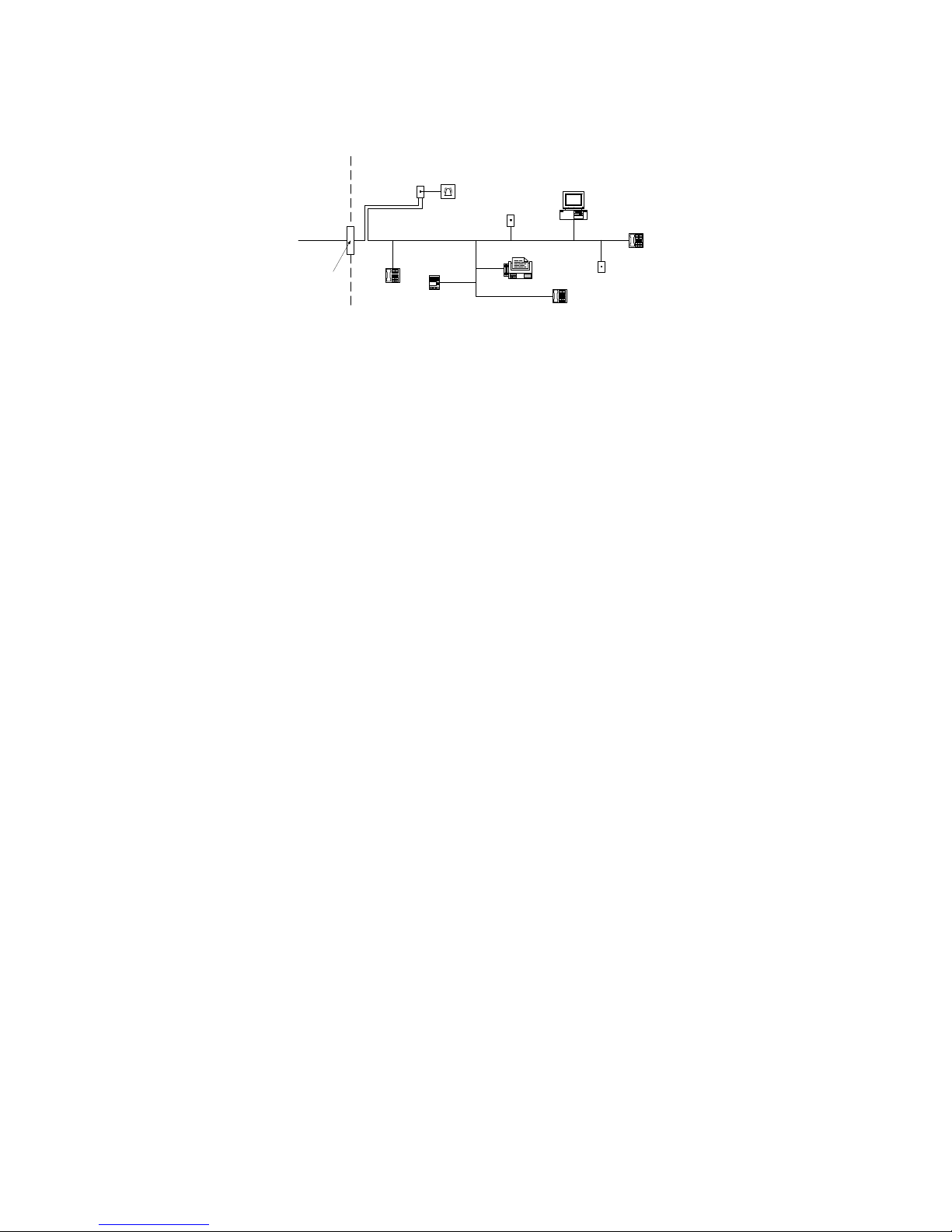
installation is depicted in the figure below. If you have any questions concerning these instructions, you should consult your telephone company or a
Telephone
Computer
Telephone
Telephone
Fax Machine
Alarm Dialing
Equipment
RJ-31X
Jack
Unused
RJ-11 Jack
Telephone
Line
Network
Service
Provider's
Facilities
Customer Premises Equipment and Wiring
Unused
RJ-11 Jack
Network
Demarcation
Point
Answering
System
qualified installer about installing the RJ-31X jack and alarm dialling equipment for you.
Industry Canada Statement
IC: 160A-SYSTEM1
NOTICE: This equipment meets the applicable Industry Canada terminal Equipment Technical Specifications. This is confirmed by the registration
number. The abbreviation, IC, before the registration number signifies that registration was performed based on a Declaration of Conformity indicating
that Industry Canada technical specifications were met. It does not imply that Industry Canada approved the equipment.
L’étiquette de l’Industrie Canada identifie le matériel homologué. Cette étiquette certifie que le matériel est conforme à certaines normes de protection,
d’exploitation et de sécurité des réseaux de télécommunications. Industrie Canada n’assure toutefois pas que le matériel fonctionnera à la satisfaction
de l’utilisateur. Le présent materiel est conforme aux specifications techniques applicables d’Industrie Canada.
NOTICE: The Ringer Equivalence Nmber (REN) for this terminal is 01. The REN assigned to each terminal equipment provides an indication of the
maximum number of terminals allowed to be connected to a telephone interface. The termination on an interface may consist of any combination of
devices subject only to the requirement that the sum of the Ringer Equivalence Numbers of all the devices does not exceed five.
This Class B digital apparatus complies with Canadian ICES-003.
L’indice d’équivalence de la sonnerie (IES) sert à indiquer le nombre maximal de terminaux qui peuvent être raccordés à une interface téléphonique.
La terminaison d’une interface peut consister en une combinaison quelconque de dispositifs, à la seule condition que la somme d’indices d’équivalence de la sonnerie de tous les dispositifs n’excède pas 5.
Cet appareil numérique de la classe B est conforme à la norme NMB-003 du Canada.
Limited Warranty
Digital Security Controls warrants the original purchaser that for a period of twelve months from the date of purchase, the product shall be free of
defects in materials and workmanship under normal use. During the warranty period, Digital Security Controls shall, at its option, repair or replace any
defective product upon return of the product to its factory, at no charge for labour and materials. Any replacement and/or repaired parts are warranted
for the remainder of the original warranty or ninety (90) days, whichever is longer. The original purchaser must promptly notify Digital Security Controls in writing that there is defect in material or workmanship, such written notice to be received in all events prior to expiration of the warranty
period. There is absolutely no warranty on software and all software products are sold as a user license under the terms of the software license agreement included with the product. The Customer assumes all responsibility for the proper selection, installation, operation and maintenance of any products purchased from DSC. Custom products are only warranted to the extent that they do not function upon delivery. In such cases, DSC can replace
or credit at its option.
International Warranty
The warranty for international customers is the same as for any customer within Canada and the United States, with the exception that Digital Security
Controls shall not be responsible for any customs fees, taxes, or VAT that may be due.
Warranty Procedure
Page 5

To obtain service under this warranty, please return the item(s) in question to the point of purchase. All authorized distributors and dealers have a warranty program. Anyone returning goods to Digital Security Controls must first obtain an authorization number. Digital Security Controls will not
accept any shipment whatsoever for which prior authorization has not been obtained.
Conditions to Void Warranty
This warranty applies only to defects in parts and workmanship relating to normal use. It does not cover:
• damage incurred in shipping or handling;
• damage caused by disaster such as fire, flood, wind, earthquake or lightning;
• damage due to causes beyond the control of Digital Security Controls such as excessive voltage, mechanical shock or water damage;
• damage caused by unauthorized attachment, alterations, modifications or foreign objects;
• damage caused by peripherals (unless such peripherals were supplied by Digital Security Controls);
• defects caused by failure to provide a suitable installation environment for the products;
• damage caused by use of the products for purposes other than those for which it was designed;
• damage from improper maintenance;
• damage arising out of any other abuse, mishandling or improper application of the products.
Items Not Covered by Warranty
In addition to the items which void the Warranty, the following items shall not be covered by Warranty: (i) freight cost to the repair centre; (ii) products which are not identified with DSC's product label and lot number or serial number; (iii) products disassembled or repaired in such a manner as to
adversely affect performance or prevent adequate inspection or testing to verify any warranty claim. Access cards or tags returned for replacement
under warranty will be credited or replaced at DSC's option. Products not covered by this warranty, or otherwise out of warranty due to age, misuse, or
damage shall be evaluated, and a repair estimate shall be provided. No repair work will be performed until a valid purchase order is received from the
Customer and a Return Merchandise Authorisation number (RMA) is issued by DSC's Customer Service.
Digital Security Controls’ liability for failure to repair the product under this warranty after a reasonable number of attempts will be limited to a
replacement of the product, as the exclusive remedy for breach of warranty. Under no circumstances shall Digital Security Controls be liable for any
special, incidental, or consequential damages based upon breach of warranty, breach of contract, negligence, strict liability, or any other legal theory.
Such damages include, but are not limited to, loss of profits, loss of the product or any associated equipment, cost of capital, cost of substitute or
replacement equipment, facilities or services, down time, purchaser’s time, the claims of third parties, including customers, and injury to property. The
laws of some jurisdictions limit or do not allow the disclaimer of consequential damages. If the laws of such a jurisdiction apply to any claim by or
against DSC, the limitations and disclaimers contained here shall be to the greatest extent permitted by law. Some states do not allow the exclusion or
limitation of incidental or consequential damages, so that the above may not apply to you.
Disclaimer of Warranties
warranty contains the entire warranty and shall be in lieu of any and all other warranties, whether expressed or implied (including all implied war-
is
Th
ranties of merchantability or fitness for a particular purpose) and of all other obligations or liabilities on the part of Digital Security Controls. Digital
Security Controls neither assumes responsibility for, nor authorizes any other person purporting to act on its behalf to modify or to change this warranty, nor to assume for it any other warranty or liability concerning this product. This disclaimer of warranties and limited warranty are governed by
the laws of the province of Ontario, Canada.
WARNING: Digital Security Controls recommends that the entire system be completely tested on a regular basis. However, despite frequent
testing, and due to, but not limited to, criminal tampering or electrical disruption, it is possible for this product to fail to perform as expected.
Out of Warranty Repairs
Digital Security Controls will at its option repair or replace out-of-warranty products which are returned to its factory according to the following conditions. Anyone returning goods to Digital Security Controls must first obtain an authorization number. Digital Security Controls will not accept any
shipment whatsoever for which prior authorization has not been obtained.
Products which Digital Security Controls determines to be repairable will be repaired and returned. A set fee which Digital Security Controls has predetermined and which may be revised from time to time, will be charged for each unit repaired.
Products which Digital Security Controls determines not to be repairable will be replaced by the nearest equivalent product available at that time. The
current market price of the replacement product will be charged for each replacement unit.
Printed In Canada
Page 6

WARNING Please Read Carefully
Note to Installers
This warning contains vital information. As the only individual in contact with system users, it is your responsibility to bring each item in this warning
to the attention of the users of this system.
System Failures
This system has been carefully designed to be as effective as possible. There are circumstances, however, involving fire, burglary, or other types of
emergencies where it may not provide protection. Any alarm system of any type may be compromised deliberately or may fail to operate as expected
for a variety of reasons. Some but not all of these reasons may be:
Inadequate Installation
A security system must be installed properly in order to provide adequate protection. Every installation should be evaluated by a security professional
to ensure that all access points and areas are covered. Locks and latches on windows and doors must be secure and operate as intended. Windows,
doors, walls, ceilings and other building materials must be of sufficient strength and construction to provide the level of protection expected. A reevaluation must be done during and after any construction activity. An evaluation by the fire and/or police department is highly recommended if this service is available.
Criminal Knowledge
This system contains security features which were known to be effective at the time of manufacture. It is possible for persons with criminal intent to
develop techniques which reduce the effectiveness of these features. It is important that a security system be reviewed periodically to ensure that its
features remain effective and that it be updated or replaced if it is found that it does not provide the protection expected.
Access by Intruders
Intruders may enter through an unprotected access point, circumvent a sensing device, evade detection by moving through an area of insufficient coverage, disconnect a warning device, or interfere with or prevent the proper operation of the system.
Power Failure
Control units, intrusion detectors, smoke detectors and many other security devices require an adequate power supply for proper operation. If a device
operates from batteries, it is possible for the batteries to fail. Even if the batteries have not failed, they must be charged, in good condition and installed
correctly. If a device operates only by AC power, any interruption, however brief, will render that device inoperative while it does not have power.
Power interruptions of any length are often accompanied by voltage fluctuations which may damage electronic equipment such as a security system.
After a power interruption has occurred, immediately conduct a complete system test to ensure that the system operates as intended.
Failure of Replaceable Batteries
This system’s wireless transmitters have been designed to provide several years of battery life under normal conditions. The expected battery life is a
function of the device environment, usage and type. Ambient conditions such as high humidity, high or low temperatures, or large temperature fluctuations may reduce the expected battery life. While each transmitting device has a low battery monitor which identifies when the batteries need to be
operate as expected. Regular testing and maintenance will keep the system in good operating condition.
replaced, this monitor may fail
Compromise of Radio Frequency (Wireless) Devices
Signals may not reach the receiver under all circumstances which could include metal objects placed on or near the radio path or deliberate jamming or
other inadvertent radio signal interference.
System Users
A user may not be able to operate a panic or emergency switch possibly due to permanent or temporary physical disability, inability to reach the device
in time, or unfamiliarity with the correct operation. It is important that all system users be trained in the correct operation of the alarm system and that
they know how to respond when the system indicates an alarm.
Smoke Detectors
Smoke detectors that are a part of this system may not properly alert occupants of a fire for a number of reasons, some of which follow. The smoke
detectors may have been improperly installed or positioned. Smoke may not be able to reach the smoke detectors, such as when the fire is in a chimney,
walls or roofs, or on the other side of closed doors. Smoke detectors may not detect smoke from fires on another level of the residence or building.
Every fire is different in the amount of smoke produced and the rate of burning. Smoke detectors cannot sense all types of fires equally well. Smoke
detectors may not provide timely warning of fires caused by carelessness or safety hazards such as smoking in bed, violent explosions, escaping gas,
improper storage of flammable materials, overloaded electrical circuits, children playing with matches or arson.
Even if the smoke detector operates as intended, there may be circumstances when there is insufficient warning to allow all occupants to escape in time
to avoid injury or death.
Motion Detectors
Motion detectors can only detect motion within the designated areas as shown in their respective installation instructions. They cannot discriminate
between intruders and intended occupants. Motion detectors do not provide volumetric area protection. They have multiple beams of detection and
motion can only be detected in unobstructed areas covered by these beams. They cannot detect motion which occurs behind walls, ceilings, floor,
closed doors, glass partitions, glass doors or windows. Any type of tampering whether intentional or unintentional such as masking, painting, or spraying of any material on the lenses, mirrors, windows or any other part of the detection system will impair its proper operation.
Passive infrared motion detectors operate by sensing changes in temperature. However their effectiveness can be reduced when the ambient temperature rises near or above body temperature or if there are intentional or unintentional sources of heat in or near the detection area. Some of these heat
sources could be heaters, radiators, stoves, barbeques, fireplaces, sunlight, steam vents, lighting and so on.
to
Page 7

Warning Devices
Warning devices such as sirens, bells, horns, or strobes may not warn people or waken someone sleeping if there is an intervening wall or door. If
warning devices are located on a different level of the residence or premise, then it is less likely that the occupants will be alerted or awakened. Audible warning devices may be interfered with by other noise sources such as stereos, radios, televisions, air conditioners or other appliances, or passing
traffic. Audible warning devices, however loud, may not be heard by a hearing-impaired person.
Telephone Lines
If telephone lines are used to transmit alarms, they may be out of service or busy for certain periods of time. Also an intruder may cut the telephone line
or defeat its operation by more sophisticated means which may be difficult to detect.
Insufficient Time
There may be circumstances when the system will operate as intended, yet the occupants will not be protected from the emergency due to their inability to respond to the warnings in a timely manner. If the system is monitored, the response may not occur in time to protect the occupants or their
belongings.
Component Failure
Although every effort has been made to make this system as reliable as possible, the system may fail to function as intended due to the failure of a
component.
Inadequate Testing
Most problems that would prevent an alarm system from operating as intended can be found by regular testing and maintenance. The complete system
should be tested weekly and immediately after a break-in, an attempted break-in, a fire, a storm, an earthquake, an accident, or any kind of construction
activity inside or outside the premises. The testing should include all sensing devices, keypads, consoles, alarm indicating devices and any other operational devices that are part of the system.
Security and Insurance
Regardless of its capabilities, an alarm system is not a substitute for property or life insurance. An alarm system also is not a substitute for property
owners, renters, or other occupants to act prudently to prevent or minimize the harmful effects of an emergency situation.
IMPORTANT - READ CAREFULLY:
DSC Software purchased with or without Products and Components is copyrighted and is purchased under the following license terms:
This End-User License Agreement (“EULA”) is a legal agreement between You (the company, individual or entity who acquired the Software and any
related Hardware) and Digital Security Controls, a division of Tyco Safety Products Canada Ltd. (“DSC”), the manufacturer of the integrated security
systems and the developer of the software and any related products or components (“HARDWARE”) which You acquired.
If the DSC software product (“SOFTWARE PRODUCT” or “SOFTWARE”) is intended to be accompanied by HARDWARE, and is NOT accompanied by new HARDWARE, You may not use, copy or install the SOFTWARE PRODUCT. The SOFTWARE PRODUCT includes computer software,
and may include associated media, printed materials, and “online” or electronic documentation.
Any software provided along with the SOFTWARE PRODUCT that is associated with a separate end-user license agreement is licensed to You under
the terms of that license agreement.
By installing, copying, downloading, storing, accessing or otherwise using the SOFTWARE PRODUCT, You agree unconditionally to be bound by the
terms of this EULA, even if this EULA is deemed to be a modification of any previous arrangement or contract. If You do not agree to the terms of
this EULA, DSC is unwilling to license the SOFTWARE PRODUCT to You, and You have no right to use it.
SOFTWARE PRODUCT LICENSE
The SOFTWARE PRODUCT is protected by copyright laws and international copyright treaties, as well as other intellectual property laws and treaties. The SOFTWARE PRODUCT is licensed, not sold.
1.GRANT OF LICENSE.
This EULA grants You the following rights:
(a)Software Installation and Use - For each license You acquire, You may have only one copy of the SOFTWARE PRODUCT installed.
(b)Storage/Network Use - The SOFTWARE PRODUCT may not be installed, accessed, displayed, run, shared or used concurrently on or from differ-
ent computers, including a workstation, terminal or other digital electronic device (“Device”). In other words, if You have several workstations, You
will have to acquire a license for each workstation where the SOFTWARE will be used.
(c) Backup Copy - You may make back-up copies of the SOFTWARE PRODUCT, but You may only have one copy per license installed at any given
time. You may use the back-up copy solely for archival purposes. Except as expressly provided in this EULA, You may not otherwise make copies of
the SOFTWARE PRODUCT, including the printed materials accompanying the SOFTWARE.
2. DESCRIPTION OF OTHER RIGHTS AND LIMITATIONS.
(a)Limitations on Reverse Engineering, Decompilation and Disassembly - You may not reverse engineer, decompile, or disassemble the SOFTWARE
PRODUCT, except and only to the extent that such activity is expressly permitted by applicable law notwithstanding this limitation. You may not
Page 8

make any changes or modifications to the Software, without the written permission of an officer of DSC. You may not remove any proprietary notices,
marks or labels from the Software Product. You shall institute reasonable measures to ensure compliance with the terms and conditions of this EULA.
(b)Separation of Components - The SOFTWARE PRODUCT is licensed as a single product. Its component parts may not be separated for use on more
than one HARDWARE unit.
(c)Single INTEGRATED PRODUCT - If You acquired this SOFTWARE with HARDWARE, then the SOFTWARE PRODUCT is licensed with the
HARDWARE as a single integrated product. In this case, the SOFTWARE PRODUCT may only be used with the HARDWARE as set forth in this
EULA.
(d)Rental - You may not rent, lease or lend the SOFTWARE PRODUCT. You may not make it available to others or post it on a server or web site.
(e)Software Product Transfer - You may transfer all of Your rights under this EULA only as part of a permanent sale or transfer of the HARDWARE,
provided You retain no copies, You transfer all of the SOFTWARE PRODUCT (including all component parts, the media and printed materials, any
upgrades and this EULA), and provided the recipient agrees to the terms of this EULA. If the SOFTWARE PRODUCT is an upgrade, any transfer
must also include all prior versions of the SOFTWARE PRODUCT.
(f)Termination - Without prejudice to any other rights, DSC may terminate this EULA if You fail to comply with the terms and conditions of this
EULA. In such event, You must destroy all copies of the SOFTWARE PRODUCT and all of its component parts.
(g)Trademarks - This EULA does not grant You any rights in connection with any trademarks or service marks of DSC or its suppliers.
3. COPYRIGHT.
All title and intellectual property rights in and to the SOFTWARE PRODUCT (including but not limited to any images, photographs, and text incorporated into the SOFTWARE PRODUCT), the accompanying printed materials, and any copies of the SOFTWARE PRODUCT, are owned by DSC or its
suppliers. You may not copy the printed materials accompanying the SOFTWARE PRODUCT. All title and intellectual property rights in and to the
content which may be accessed through use of the SOFTWARE PRODUCT are the property of the respective content owner and may be protected by
applicable copyright or other intellectual property laws and treaties. This EULA grants You no rights to use such content. All rights not expressly
granted under this EULA are reserved by DSC and its suppliers.
4. EXPORT RESTRICTIONS.
You agree that You will not export or re-export the SOFTWARE PRODUCT to any country, person, or entity subject to Canadian export restrictions.
5. CHOICE OF LAW:
This Software License Agreement is governed by the laws of the Province of Ontario, Canada.
6. ARBITRATION
All disputes arising in connection with this Agreement shall be determined by final and binding arbitration in accordance with the Arbitration Act, and
’
the parties agree to be bound by the arbitrator
s decision. The place of arbitration shall be Toronto, Canada, and the language of the arbitration shall be
English.
7. LIMITED WARRANTY
(i)NO WARRANTY
DSC PROVIDES THE SOFTWARE “AS IS” WITHOUT WARRANTY. DSC DOES NOT WARRANT THAT THE SOFTWARE WILL MEET
YOUR REQUIREMENTS OR THAT OPERATION OF THE SOFTWARE WILL BE UNINTERRUPTED OR ERROR-FREE.
(j)CHANGES IN OPERATING ENVIRONMENT
DSC shall not be responsible for problems caused by changes in the operating characteristics of the HARDWARE, or for problems in the interaction of
the SOFTWARE PRODUCT with non-DSC-SOFTWARE or HARDWARE PRODUCTS.
(k)LIMITATION OF LIABILITY; WARRANTY REFLECTS ALLOCATION OF RISK
IN ANY EVENT, IF ANY STATUTE IMPLIES WARRANTIES OR CONDITIONS NOT STATED IN THIS LICENSE AGREEMENT, DSC’S
ENTIRE LIABILITY UNDER ANY PROVISION OF THIS LICENSE AGREEMENT SHALL BE LIMITED TO THE GREATER OF THE
AMOUNT ACTUALLY PAID BY YOU TO LICENSE THE SOFTWARE PRODUCT AND FIVE CANADIAN DOLLARS (CAD$5.00).
BECAUSE SOME JURISDICTIONS DO NOT ALLOW THE EXCLUSION OR LIMITATION OF LIABILITY FOR CONSEQUENTIAL OR
INCIDENTAL DAMAGES, THE ABOVE LIMITATION MAY NOT APPLY TO YOU.
(l)DISCLAIMER OF WARRANTIES
THIS WARRANTY CONTAINS THE ENTIRE WARRANTY AND SHALL BE IN LIEU OF ANY AND ALL OTHER WARRANTIES,
WHETHER EXPRESSED OR IMPLIED (INCLUDING ALL IMPLIED WARRANTIES OF MERCHANTABILITY OR FITNESS FOR A PARTICULAR PURPOSE) AND OF ALL OTHER OBLIGATIONS OR LIABILITIES ON THE PART OF DSC. DSC MAKES NO OTHER WARRANTIES. DSC NEITHER ASSUMES NOR AUTHORIZES ANY OTHER PERSON PURPORTING TO ACT ON ITS BEHALF TO MODIFY OR TO
CHANGE THIS WARRANTY, NOR TO ASSUME FOR IT ANY OTHER WARRANTY OR LIABILITY CONCERNING THIS SOFTWARE
PRODUCT.
(m)EXCLUSIVE REMEDY AND LIMITATION OF WARRANTY
UNDER NO CIRCUMSTANCES SHALL DSC BE LIABLE FOR ANY SPECIAL, INCIDENTAL, CONSEQUENTIAL OR INDIRECT DAMAGES BASED UPON BREACH OF WARRANTY, BREACH OF CONTRACT, NEGLIGENCE, STRICT LIABILITY, OR ANY OTHER LEGAL
THEORY. SUCH DAMAGES INCLUDE, BUT ARE NOT LIMITED TO, LOSS OF PROFITS, LOSS OF THE SOFTWARE PRODUCT OR ANY
Page 9

ASSOCIATED EQUIPMENT, COST OF CAPITAL, COST OF SUBSTITUTE OR REPLACEMENT EQUIPMENT, FACILITIES OR SERVICES,
DOWN TIME, PURCHASERS TIME, THE CLAIMS OF THIRD PARTIES, INCLUDING CUSTOMERS, AND INJURY TO PROPERTY.
WARNING: DSC recommends that the entire system be completely tested on a regular basis. However, despite frequent testing, and due to, but not
limited to, criminal tampering or electrical disruption, it is possible for this SOFTWARE PRODUCT to fail to perform as expected.
Page 10

Table of Contents
Chapter 1 - Introduction ............................................................................................8
Features ....................................................................................................................................................9
Software Compatibility ............................................................................................................................9
Approvals ...............................................................................................................................................10
Industry Approvals ........................................................................................................................................... 10
UL864 Programming Requirements ............................................................................................................................10
For UL and ULC listed applications the following UL/ULC listed printers can be used with the System I: ............. 11
Specifications .........................................................................................................................................12
Electrical ...................................................................................................................................................................... 12
Environmental ..............................................................................................................................................................12
Dimensions .................................................................................................................................................................. 12
Ethernet Interfaces .......................................................................................................................................................12
Accounts ...................................................................................................................................................................... 12
Printers .........................................................................................................................................................................12
Buffers .......................................................................................................................................................................... 12
Out of Box ..............................................................................................................................................12
SG-System I .................................................................................................................................................................12
SG-System Rackmount Kit (Optional) - required for UL/ULC Listed Installations ...................................................13
Additional Equipment Required (Not Supplied) .........................................................................................................13
Chapter 2 - Installation ............................................................................................14
Controls and Indicators ..........................................................................................................................15
Set Up and Testing .................................................................................................................................18
The following items are required: ................................................................................................................................ 18
For UL/ULC Installations ............................................................................................................................................19
For CE Installations .....................................................................................................................................................19
Warning: ...................................................................................................................................................................... 19
Chapter 3 - Operation ..............................................................................................22
Operation ................................................................................................................................................23
Active Mode ...................................................................................................................................................... 23
Manual Mode .................................................................................................................................................... 23
Program Category ............................................................................................................................................. 24
Password ......................................................................................................................................................................24
User Interface ............................................................................................................................................................... 24
Top Level Menu ................................................................................................................................................ 25
View or Change Options ..............................................................................................................................................25
View Printer Buffer ......................................................................................................................................................25
System Functions .........................................................................................................................................................25
Exit Programming ........................................................................................................................................................25
System Functions Menu .................................................................................................................................... 25
System Information ......................................................................................................................................................25
Change Date and Time .................................................................................................................................................26
Default SG-System I ....................................................................................................................................................26
Reset SG-System I .......................................................................................................................................................26
Visual Indicator Test ....................................................................................................................................................26
Exit Menu ..................................................................................................................................................................... 26
Miscellaneous LED Indicators .......................................................................................................................... 26
1
Page 11

View Trouble ...............................................................................................................................................................26
Trouble List ..................................................................................................................................................................27
View Network / Watchdog ..........................................................................................................................................27
View Status ..................................................................................................................................................................27
Chapter 4 - Options: System ...................................................................................28
System Option Index ..............................................................................................................................29
Steps required to access an option and change its setting or value ........................................................29
System Options .......................................................................................................................................30
Option 001: LAN IP Address ......................................................................................................................................30
Option 002: LAN Subnet Mask Address .....................................................................................................................30
Option 003: LAN Gateway ..........................................................................................................................................30
Option 004: Auto Update Time and Date ....................................................................................................................30
Option 005: Contrast ....................................................................................................................................................30
Option 006: Password ..................................................................................................................................................31
Option 007: Automation Baud Rate ............................................................................................................................31
Option 008: Automation Data Bits ..............................................................................................................................31
Option 009: Automation Parity.....................................................................................................................................32
Option 00A: Serial Printer Format ............................................................................................................................... 32
Option 00B: Serial Baud Rate...................................................................................................................................... 32
Option 00C: Serial Data Bits .......................................................................................................................................32
Option 00D: Serial Printer Parity ................................................................................................................................. 33
Option 00E: AHS Operations Time .............................................................................................................................33
Option 00F: B32 Headers ............................................................................................................................................ 33
Option 012: Heartbeat Timer .......................................................................................................................................33
Option 013: Buzzer Tone .............................................................................................................................................34
Option 014: Receiver Number .....................................................................................................................................34
Option 015: Printer Test ............................................................................................................................................... 34
Option 020: Mask UPS AC ..........................................................................................................................................35
Option 021: Mask UPS BAT .......................................................................................................................................35
Option 024: Mask SG TCP/IP ..................................................................................................................................... 35
Option 025: Mask SG Serial ........................................................................................................................................35
Option 028: Mask TCP Printer ....................................................................................................................................35
Option 029: Mask Parallel Printer ...............................................................................................................................36
Option 02A: Mask Serial Printer .................................................................................................................................36
Option 02F: Automation Mode ....................................................................................................................................36
Option 030: Printer Mode ............................................................................................................................................37
Option 031: ACK Wait ................................................................................................................................................ 38
Option 032: Date Format .............................................................................................................................................39
Options 037 and 038: License Keys #1, #2 .................................................................................................................39
Option 039: Mask USB Printer ....................................................................................................................................39
Option 03A: Programmable I/O ...................................................................................................................................39
Option 03B: Last Message On .....................................................................................................................................40
Option 03C: LCD Backlight Colour ............................................................................................................................40
Option 03D: Key Backlight Colour .............................................................................................................................40
Option 040: Number of Channels ................................................................................................................................41
Option 041: System Number Length ...........................................................................................................................41
Option 042: Busy Out ..................................................................................................................................................42
Option 043: System Protocol ID ..................................................................................................................................42
Option 044: System CLASS Field ...............................................................................................................................43
Chapter 5 - Options: Channels 1 and 2 ...................................................................44
Channel Option Index ............................................................................................................................45
Steps required to access an option and change its setting or value ........................................................46
2
Page 12

Static Options .........................................................................................................................................46
Option 101: Line Card Number ...................................................................................................................................46
Option 104: Two-Way Activation Time ......................................................................................................................46
Option 105: Pre-H.S. Duration ....................................................................................................................................47
Option 109: First Ring Length .....................................................................................................................................47
Option 10D: Ring Select.............................................................................................................................................. 47
Option 10E: Backup Line Option ................................................................................................................................47
Option 111: Hook Flash Enable ...................................................................................................................................48
Option 112: Caller Source ID .......................................................................................................................................48
Option 113: Caller Source to SG Automation .............................................................................................................49
Option 114: Caller Source to Printer ...........................................................................................................................49
Option 117: DMP User Length ....................................................................................................................................50
Option 118: DMP User Length ....................................................................................................................................50
Option 119: Fault Call Counter ....................................................................................................................................51
Option 11A: DNIS Input Sensitivity ............................................................................................................................51
Option 11F: Debug Option ..........................................................................................................................................52
Option 125: Phone Line Voltage Select .......................................................................................................................52
Option 127: Caller Source Process ..............................................................................................................................52
Option 12A: Hook Flash Delay ...................................................................................................................................52
Option 12C: Dialer Presence .......................................................................................................................................53
Option 12D: AHS ........................................................................................................................................................53
Option 12F: Online Timeout ........................................................................................................................................53
Dynamic Options ....................................................................................................................................54
Options 130-13F: 3/1 - 4/1 Digit 0-F ........................................................................................................................... 54
Options 140-14F: 3/2 - 4/2 Digit 0-F ........................................................................................................................... 54
Options 150-15F: 4/3 Digit 0-F ...................................................................................................................................54
Options 160-16F: Printer Words ..................................................................................................................................55
Option 170: Automation Common Event Code........................................................................................................... 55
Option 171: Library Select ...........................................................................................................................................56
Option 172: SIA Option ...............................................................................................................................................57
Option 173: Input/Output Sensitivity ...........................................................................................................................59
Option 174: Equivalent Line Number.......................................................................................................................... 59
Option 175: Receiver Number .....................................................................................................................................59
Option 176: Accounts 3/x - 4/x ....................................................................................................................................59
Option 177: Digit Replace ...........................................................................................................................................60
Option 178: Maximum Inter-Digit ...............................................................................................................................60
Option 179: Maximum Inter-Burst ..............................................................................................................................60
Option 17A: Four- and Five-Digit Account Codes To Activate Two-Way Radio ......................................................61
Option 17B: Three-Digit Account Codes To Activate Two-Way Radio ....................................................................61
Option 17C: Audio Alarm Code Range .......................................................................................................................61
Option 17D: Audio Zone Code .................................................................................................................................... 62
Option 17E: Audio RS-232...........................................................................................................................................62
Option 17F: Audio Format ...........................................................................................................................................62
Option 180: Kiss-off to Hang-up .................................................................................................................................63
Options 181 - 188: Handshake Selection .....................................................................................................................63
Options 189 - 190: Handshake and Kiss-off Duration ................................................................................................. 65
Option 191: Inter-Handshake Duration ....................................................................................................................... 66
Option 192: Pulse Mode ..............................................................................................................................................67
Option 193: Minimum Audio Tone .............................................................................................................................67
Option 194: Account Digit Stripping ...........................................................................................................................67
Option 195: Five- and Six-Digit Pulse ......................................................................................................................... 69
Option 196: 4/1 Extended ............................................................................................................................................70
Option 197: 4/2 Extended ............................................................................................................................................ 70
3
Page 13

Option 198: 3/1 Extended ............................................................................................................................................70
Option 199: Ademco Express ......................................................................................................................................71
Option 19A: Error Counter ..........................................................................................................................................71
Option 19B: Echo Canceller ........................................................................................................................................ 71
Option 19C: Acron RS-232 .........................................................................................................................................71
Option 19D: Modem II RS-232 ...................................................................................................................................72
Option 19E: Scantronics Select ...................................................................................................................................72
Option 19F: Ademco High Speed RS-232 ................................................................................................................... 72
Option 1A0: 11-/12-Digit DTMF (Acron, Scantronics, or Scancom 433) ..................................................................73
Option 1A1: FBI RS-232 .............................................................................................................................................74
Option 1A2: Digit Replace ..........................................................................................................................................74
Option 1A3: D6500 RS232 ..........................................................................................................................................74
Option 1A4: BFSK RS-232 ......................................................................................................................................... 75
Option 1A5: Sescoa Super Speed ................................................................................................................................76
Option 1A6: ITI Adjust ................................................................................................................................................76
Option 1A7: Silent Knight FSK2 RS-232 ...................................................................................................................76
Option 1A8-1AF: Dial-Out Number for Two-Way Audio Transfer ...........................................................................77
Option 1B0: CCITT Audio Format Enable Bits ..........................................................................................................78
Option 1B1: DMP Area BIN or DEC Option .............................................................................................................. 78
Option 1B2: Format Disable ........................................................................................................................................79
Chapter 6 - Options: IP ...........................................................................................80
IP Option Index ......................................................................................................................................81
Steps required to access an option and change its setting or value ........................................................81
IP Options .................................................................................................................................................1
Option 30D: Alarm Port Number ................................................................................................................................81
Option 30F: Receiver Number .....................................................................................................................................82
Option 310: Line Card Number ...................................................................................................................................82
Option 313: Transmitter Failure Debounce Time ........................................................................................................82
Option 315: Transmitter Restoral Debounce Time ......................................................................................................82
Option 319: Mask Transmitter Restoral ......................................................................................................................82
Option 31A: Mask Transmitter Failure ........................................................................................................................82
Option 31B: Mask Transmitter Swap ..........................................................................................................................83
Option 31C: Mask Transmitter Unencrypted ..............................................................................................................83
Option 31D: Mask Invalid Report ...............................................................................................................................83
Option 31E: Mask Unknown Account .........................................................................................................................83
Option 31F: Mask Supervised Acc Exceeded ............................................................................................................. 84
Option 320: Mask Transmitter Deleted .......................................................................................................................84
Option 33A: Account Port ...........................................................................................................................................84
Option 340: Account Password ...................................................................................................................................84
Option 344: DNIS Replacement of RRLLL ................................................................................................................84
Option 346: Account Digit Strip .................................................................................................................................. 85
Option 347: SIM ID Output .........................................................................................................................................85
Appendix A - Events and Messages ........................................................................88
Appendix B - Ports ..................................................................................................94
Parallel Printer Port ................................................................................................................................95
Serial Printer Port (COM2) ....................................................................................................................96
RS-232 Serial Automation .....................................................................................................................96
I/O Port ...................................................................................................................................................97
I/O Ports - Detailed Descriptions ...................................................................................................................... 97
Appendix C - Compatible IP Formats ...................................................................100
4
Page 14

Appendix D - Printer Words .................................................................................102
Appendix E - Profiles ............................................................................................106
5
Page 15
Introduction
In This Chapter...
Features on page 9
Software Compatibility on page 9
Approvals on page 10
Specifications on page 12
Out of Box on page 12
Page 16
CHAPTER ONE - INTRODUCTION
1
Features
The SG-System I is a dual phone line / IP network receiver intended for the remote monitoring of residential / commercial fire and burglary
alarm systems. The system can be configured for desktop stand-alone operation (vertical stacking of up to 4 systems) or rack mounting (see
Note below). The SG-System I can monitor up to 512 IP accounts. Please refer to Table 4: Loading Capacities for Hunt Groups on
page 18 for maximum capacities when communication over PSTN. The receiver can be connected to a USB port or Ethernet port on any
computer running SG System Console software for system programming and printer messages. The receiver provides several connection
options for Serial RS232 printers and Parallel printers.
The SG-System I is a pluggable equipment type A, using a detachable power supply cord.
The SG-System I real-time clock and calendar stamps receive alarm data which are transmitted to a central station computer via a TCP/IP
connection and/or a Serial port using either a standard COM port and/or a USB port.
System configuration can be undertaken using a PC with SG-System I Console Software installed, or locally using the scroll buttons and the
LCD on the front panel of the unit.
NOTE: System must be rack mounted for UL and ULC Listed Installations.
SG-System I features include the following:
• Dual Telco Interface
• Independent options list for each channel
• Remote alarm ACK button
•Caller ID
• SG-Systems Console Software (one software package for SG-System I, II receivers)
• Ability to call out to other receivers to check the communication path
• Ability to disable a telephone line
• Selectable buzzer output tones
• LCD and keymat can cycle through colours and fade colours in / out
• IP (FIBRO) communications with alarm panels and transmitters / Software-controlled features
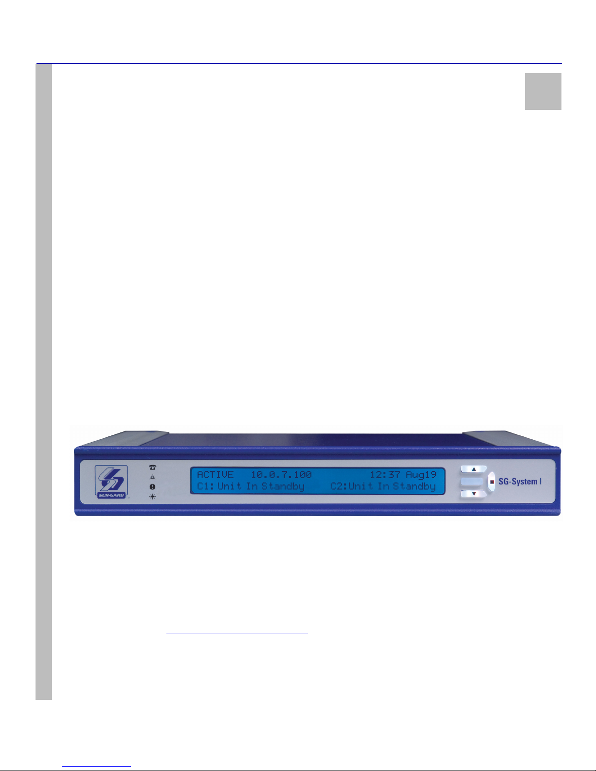
Figure 1: SG-System I Receiver
SG-System I Operating Manual
Software Compatibility
The following examples of Central Station automation software are compatible with the SG-System I interface:
MAS DICE SIMS II GENESYS S.I.S.
IBS MicroKey ABM Bold
Refer to the DSC website - http://www.dsc.com/Default.aspx?id=79 - for a comprehensive list of compatible Automation Software
Manufacturers.
NOTE: Automation connections are considered supplementary as per UL864 listing. Compatibility with central station automation software is intended to be handled under a separate UL1981 software and/or site certification evaluation.
9
Page 17
CHAPTER ONE - INTRODUCTION
Approvals
Industry Approvals
The System I meets the following standards:
• UL 1610 Central Station Burglar Alarm Units
• UL 864 Standard for Fire Alarm System Control Units and Accessories
• UL 1635 Digital Alarm Communicator System Units
• CAN/ULC-S304-06 Signal Receiving Centre and Premises Burglar Alarm Control Units
• CAN/ULC-S559-04 Equipment for Fire Signal Receiving Centres and Systems
• EN60950-1:2001 Standard for Information Technology Equipment
• AS/NZS 60950.1:2003 Information Technology Equipment - Safety, Part 1: General Requirements
• CISPR22 Class B Information Technology Equipment - Radio Disturbance Characteristics - Limits and Methods of Measurements
• EN50130-4 Immunity requirements for components of Fire, Intruder, and Social Alarm Systems.
This equipment shall be installed in the USA in accordance with the requirements of NFPA72, NFPA70, and the authority having jurisdiction.
In Canada, the equipment is ULC listed for active communication channel security levels A1~A4 when used in conjunction with T-Link
TL250 and T-Link TL300 Internet/Intranet alarm communicators. For this type of application the supervision and encryption features have
to be enabled. When used in conjunction with digital diallers, the receiver can provide passive communication channel security levels
P1~P3.
For ULC Installations the equipment shall be installed in accordance with the requirements of ULC-S561, ULC-S301 and the authority having jurisdiction.
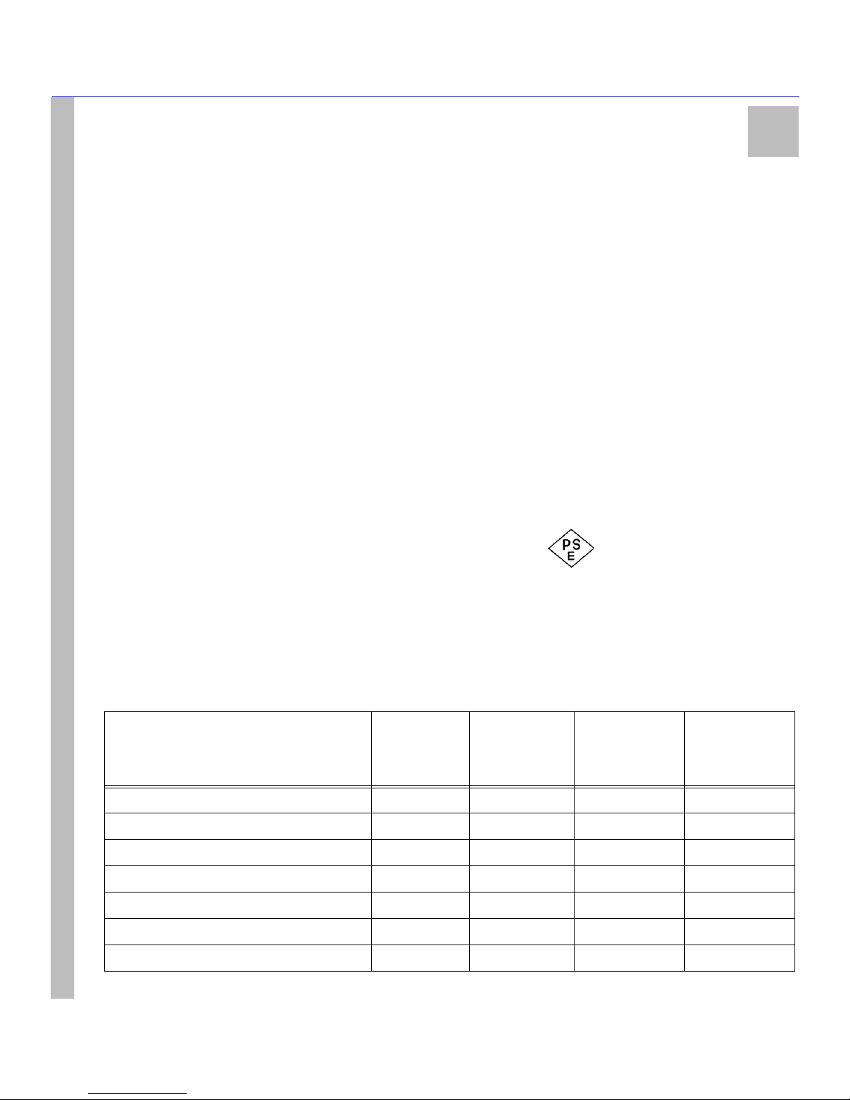
For installations in Japan, the power supply cord must be a PSE / JET Approved Type power cord with a female end type (IEC). It must meet
1
fully the DENAN Law Category A equipment and be marked with the diamond PSE logo .
UL864 Programming Requirements
NOTE: To all Users, Installers, Authorities having Jurisdiction, and other involved parties. This product incorporates field pro-
SG-System I Operating Manual
grammable software. In order for the product to comply with the requirements in the Standard for Control Units and Accessoriesfor Fire Alarms Systems, UL 864, certain programming features or options must be limited to specific values or not used at all, as
indicated in the table below.
Table 1: UL864 Programming Requirements
Permitted in
Option number and name
UL 864?
(Y/N)
Option 013: Buzzer Tone N ON/OFF ON ON
Option 020: Mask UPS AC N ON/OFF OFF --
Option 021: Mask UPS BAT N ON/OFF OFF --
Option 024: Mask SG TCP/IP N ON/OFF OFF OFF
Option 025: Mask SG Serial N ON/OFF OFF OFF
Option 028: TCP Printer N ON/OFF OFF OFF
Option 029: Mask Parallel Printer N ON/OFF OFF OFF
Possible
settings
Settings
permitted
(UL 864)
Settings
permitted
(ULC)
10
Page 18
CHAPTER ONE - INTRODUCTION
Table 1: UL864 Programming Requirements
1
Permitted in
Option number and name
UL 864?
(Y/N)
Option 02A: Mask Serial Printer N ON/OFF OFF OFF
Option 12C: Dialer Presence Y 00/01/02 00/01/02 00
Option 12F: Online Timeout Y 01-FF (1-255sec) 1E (30sec) 1E (30sec)
Option 039: Mask USB Printer N ON/OFF OFF OFF
Option 040: Number of Channels Y C1/C2/IP C1+C2/
Option 042: Busy Out N 00/01/04/05 00 00
Option 105: Pre-H.S. Duration Y 0A-FF (10-
Option 109: First Ring Length Y 01-FF (1-255sec) 05 (5sec)-max 05 (5sec)-max
Option 181-188: Handshake Selection Y 23/14/2D/0C/0E 2D/0C Options 181-183:
Option 189, 190: Handshake and Kiss-off Duration Y 100msec - 8.1sec 00 (1sec) 00 (1sec)
Possible
settings
255sec)
Settings
permitted
(UL 864)
C1+C2+IP/C1+IP
0A (10sec) 0A (10sec)
Settings
permitted
(ULC)
C1+C2/
C1+C2+IP/C1+IP
Options 184-188
not used
2D/0C;
Option 191: Inter-Handshake Duration Y 00-09 (1-9sec) 00-04 (1-4sec) 00-04 (1-4sec)
SG-System I Operating Manual
Option 313: Transmitter Failure Debounce Time Y 1E-fd20 (30-
64800sec)
Option 315: Transmitter Restoral Debounce Time Y 1E-FF (30-
255sec)
Option 319: Mask Transmitter Restoral N ON/OFF OFF OFF
Option 31A: Mask Transmitter Failure N ON/OFF OFF OFF
Option 31B: Mask Transmitter Swap N ON/OFF OFF OFF
Option 31C: Mask Transmitter Unencrypted N ON/OFF OFF OFF
Option 31D: Mask Invalid Report N ON/OFF OFF OFF
Option 31E: Mask Unknown Account N ON/OFF OFF OFF
Option 31F: Mask Supervised Acc Exceeded N ON/OFF OFF OFF
For UL and ULC listed applications the following UL/ULC listed printers can be used with the System I:
Parallel Printers
• Seiko DPU-414
Serial Printers
05A (90sec) 05A (90sec)
3C (60sec) 3C (60sec)
11
Page 19

CHAPTER ONE - INTRODUCTION
• Seiko DPU-414
NOTE: Do not use printer cables that have only 1 common ground wire.
Specifications
Electrical
Input Voltage ...................................................................................................................................................... 100-240VAC, 50-60Hz.
Input Current .......................................................................................................................................................................... 0.7A (Max)
Backup Power Supply External UPS .................................................................................................................................. (not supplied)
Maximum Power Consumption .................................................................................................................................................. 25 Watts
Environmental
Temperature ........................................................................................................................................................... 0-49°C (32 - 120.2°F)
Humidity ......................................................................................................................................................... 93%RH, Non-Condensing
Dimensions
Width ................................................................................................................................................................................ 12in. (305mm)
Length .......................................................................................................................................................................... 12.25in. (311mm)
Height .............................................................................................................................................................................. 1.75in. (45mm)
Weight .......................................................................................................................................................................... 7.92lbs (3.58 Kg)
Ethernet Interfaces
Automation Port ................................................................................................................................................................................ 1025
Printer Port ........................................................................................................................................................................................ 1027
Command Port (Console Interface) .................................................................................................................................................. 1024
Debug Port ........................................................................................................................................................................................ 1030
TFTP Port ............................................................................................................................................................................................. 69
Account Port (Default) ..................................................................................................................................................................... 3064
Accounts
Supervised for Communication over PSDN ............................................................................................................................. 512 MAX
SG-System I Operating Manual
ULC Line Security Levels .....................................................................................A1-A4 (active channels) or P1-P3 (passive channels)
Refer to Table 4: Loading Capacities for Hunt Groups on page 18for loading capacities when using Communication over PSTN
Printers
Parallel ..................................................................................................................................................DMP-SCS-PTR, Seiko DPU-414
Serial ................................................................................................................................................................................Seiko DPU-414
DACT Compatible communication formats (ULC passive channels) .......................................................................................SIA, CID
Encryption ..............................................................................................................................................................................AES 128 bit
NOTE: Do not use printer cables that have only one common ground wire.
Buffers
POTS ........................................................................................................................................................................................500 events
IP ..............................................................................................................................................................................................512 events
System ........................................................................................................................................................................................50 events
1
Table 2: SG-System I Specifications
Out of Box
Verify that you have received the following:
SG-System I
SG-System I Receiver .......................................................................................................................................................................Qty 1
SG-Systems Console Software CD ................................................................................................................................................. Qty 1
SG-System I Quick Install Guide ......................................................................................................................................................Qty 1
12
Page 20

CHAPTER ONE - INTRODUCTION
Height-Adjustable Rubber Feet (front) ..............................................................................................................................................Qty 2
Rubber Feet (rear) ..............................................................................................................................................................................Qty 2
SG-System Rackmount Kit (Optional) - required for UL/ULC Listed Installations
Brackets .............................................................................................................................................................................................Qty 2
Rails (Mounting) ...............................................................................................................................................................................Qty 4
Screws ...............................................................................................................................................................................................Qty 8
Quick Install Sheet .............................................................................................................................................................................Qty 1
Additional Equipment Required (Not Supplied)
IEC Power Line Cord ........................................................................................................................................................................Qty 1
CAT-5 Ethernet Cable for Network Interface Port or USB Cable for Console Communication ......................................................Qty 1
DB9 Terminated RS232 Serial Cable ................................................................................................................................................Qty 1
DB25 Terminated Parallel Printer Cable ...........................................................................................................................................Qty 1
Phone Line Cable with RJ11 Jack (minimum 26 AWG) ...................................................................................................................Qty 2
1
SG-System I Operating Manual
13
Page 21

Installation
In This Chapter...
Controls and Indicators on page 15
Set Up and Testing on page 18
Page 22
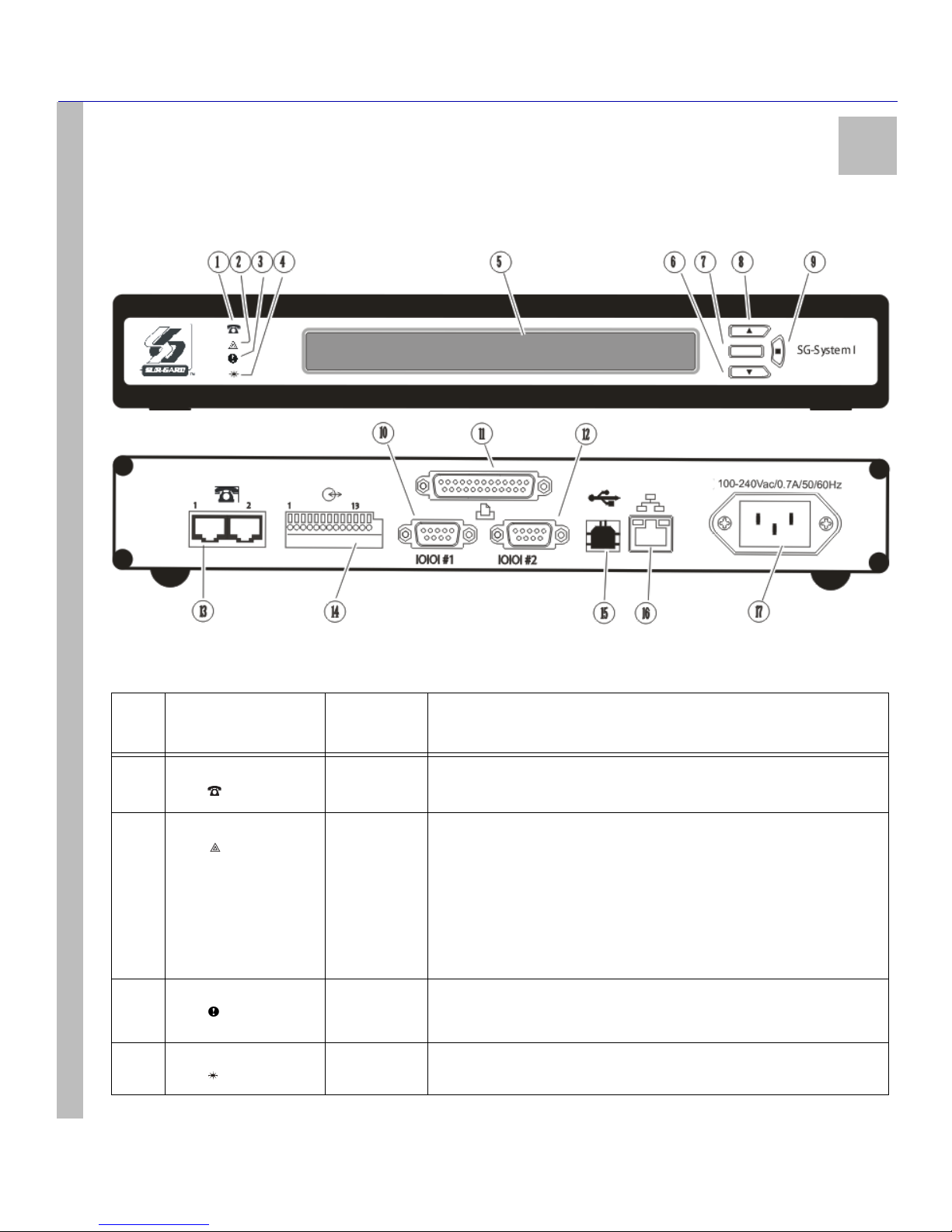
Controls and Indicators
Figure 2: Controls and Indicators
CHAPTER TWO - INSTALLATION
2
Table 3: SG-System I Front and Rear Panel Descriptions
Item
SG-System I Operating Manual
no.
1 TELEPHONE Red
2STATUS Orange
3 TROUBLE Yellow
4 WATCHDOG Blue
Indicator/ Control/
Connector
LED
LED
LED
LED
State/Pin
OFF
ON
FLASHING
OFF
ON
OFF
FLASHING
STEADY
Description
Both Telphone Lines are Present.
At least One Telephone Line is Absent.
Two Flashes indicates a Trouble as described below:
• Time Not Set
•Computer Buffer Full
•Printer Buffer Full
• Software Corruption
• Line Test Active
Normal Operation.
Indicates any System Trouble not related to network or alarm (Note that the
LCD backlight will override the programmed colour and change to Yellow).
No System Trouble.
Normal Operation (Software watchdog toggles every 200msec).
SG-System I Fault.
15
Page 23
CHAPTER TWO - INSTALLATION
Table 3: SG-System I Front and Rear Panel Descriptions
2
Item
no.
5 LCD Display 40x2 character LCD display.
6 DOWN Interface Button Scrolls down through menu options.
7 ACK Interface Button/
8 UP Interface Button Scrolls up through menu options.
9 ENTER Interface Button Selects a menu option.
10 AUTOMATION Port
Indicator/ Control/
Connector
LED
(COM1)
State/Pin
Top line displays current Operating Mode.
Bottom line displays Trouble or received messages in Manual mode.
Alarm: If an alarm is present while the system is in Manual mode, the LCD
backlight will change to Red - overriding the programmed colour - and the
ACK button will flash. In addition, a buzzer will sound with each flash of the
ACK button.
Alarms received but not yet displayed are identified by a solid arrow symbol on
the far right edge of the LCD.
FLASHING
OFF
DB9 Sends automation messages to central station computer (e.g. heartbeat if no
Indicates unit is in Manual Mode and waiting for acknowledgement.
There are no alarm events requiring acknowledgement.
The ACK button is used to acknowledge an alarm event in Manual Mode. It
cannot acknowledge all alarms with one press, but must be pressed for each
individual alarm.
activity).
NOTE: Maximum cable length is 1.8m (6ft). Longer cables may
impair performance.
Description
11 PARALLEL PRINTER
SG-System I Operating Manual
12 SERIAL PRINTER Port
13 Telephone Line Input 2 x RJ-11 For connection with PSTN (alarm reporting connections using digital diallers-
Port
(COM2)
DB25
(Female)
DB9 RS232 Serial Printer Port. Sends events to local printer.
Sends events to local printer (DB25 Female).
NOTE: Maximum cable length is 1.8m (6ft). Longer cables may
impair performance.
NOTE: Maximum cable length is 1.8m (6ft). Longer cables may
impair performance.
DACT).
Pins 3 and 4 are line-in; pins 2 and 5 are backup channel line-in or two-way
audio connection.
16
Page 24
CHAPTER TWO - INSTALLATION
Table 3: SG-System I Front and Rear Panel Descriptions
2
Item
no.
14 I/O Port ( Use AWG 18-
15 USB Port USB Type B USB Type B. The USB port on SG System I is used to connect with a Windows
SG-System I Operating Manual
16 LAN Interface Port CAT-5 This interface connects to the local network. Also, it is through this interface
Indicator/ Control/
Connector
22 wire)
State/Pin
1 Input
2 ~
3 Input
4 Input
5 ~
6 Input
7 Output R1*
8 R1
9 Output R2
10 R2
11 Ou t pu t R 3
12 R3
13 ~
Description
UPS AC Failure (toggles from ground to open on failure)
Common (ground)
UPS DC Failure (toggles from ground to open on failure)
Remote ACK button - identical functionality to ACK button on LCD
Common (ground)
Future Use
Follow Buzzer: relay contact closes following Buzzer output activations (synchronized)
Relay Common
Trouble Output: relay contact closes when the Trouble LED activates
Relay Common
Network Status: relay contact closes when the Network Status icon appears on
the LCD
Relay Common
Earth (ground)
NOTE: Maximum cable length is 1.8m (6ft). Longer cables may
impair performance. The use of shielded cable is recommended.
NOTE: Relays are rated for 12Vdc 100ma.
NOTE: Inputs are rated for 20ma open collector.
*Rx is the relay number; as a rule, these outputs are open connections
host running the SG-Systems Console Software. Other operating systems are
not supported.
NOTE: Maximum cable length is 1.8m (6ft). Longer cables may
impair performance.
that a connection is made to the console software and the automation software.
NOTE: Maximum cable length is 100m (328ft). Longer cables may
impair performance.
17 Mains Supply Connector 120/240VAC /0.7A/ 50-60Hz
For ULC installations Canada, the equipment shall be rack-mounted and powered by a permanently wired supply in accordance with C22.1, Canadian Electrical Code, Part 1, Safety Standard for Electrical Installations, section 32. Please refer to on
page 19. This equipment is intended to utilize the building emergency AC supply system for their standby supply (e.g. UPS,
batteries in conjunction with engine-driven generators).
NOTE: The LED indicators and the LCD can be tested for integrity by accessing the following in the main programming
menu: item 3 - System Functions > item 5 - Visual Indicators Test.
NOTE: For equipment used at Signal Receiving Centres and intended to facilitate IP communication (hubs, routers, NID,
DSL/cable modems) 24hr backup power is required.
NOTE: When using Private, Corporate, and high-speed data networks, network access and domain access policies will be
set to restrict unauthorised network access and ‘spoofing’ or ‘denial of service’ attacks. Select an ISP that provides redundant servers/systems, backup power, routers with firewalls enabled and methods to identify and protect against these types
of attacks (‘i.e. ‘spoofing’, ‘dos’).
17
Connection to Interruptible Power Supply (UPS recommended) with minimum
24 hr. standby capability required.
Refer to Set Up and Testing on page 18.
Page 25

CHAPTER TWO - INSTALLATION
NOTE: Firewall protection must be designed in such a way that the Automation software port connected to the SG-System I
alarm receiver is protected from external attacks (e.g. ‘spoofing’, ‘DOS’).
Set Up and Testing
NOTE: Install external devices connected to items (10)-(16) in the same room as the SG-System I. Maintain 6.5mm (1/4”) of
separation between power limited and non-power limited circuits. Use power limited, supervised circuits only.
Familiarization with the connections and setup of the unit will make the final installation simpler. DSC recommends that the user gather all
elements of the system and stage a successful trial run before going live.
The following items are required:
• IEC power supply cord
• CAT5 Ethernet cable
• Phone line, dialer
• Hub/router or network
NOTE: When a Hub or Router/Gateway is used with the SG-System I, 24 hr standby power is required for these devices (i.e.
UL listed UPS, Battery Backup, or engine driven generator).
Take the following steps:
2
SG-System I Operating Manual
1. Unpack the SG-System I components. Remove the unit and inspect for shipping damage. If any damage is apparent, notify the carrier immediately.
2. Install the rack-mount brackets or the rubber feet in the indents as required.
3. Connect telephone.
4. Connect the main power using a standard computer IEC cable (not supplied). See the wiring diagram below.
5. The LCD will power up and display internal Troubles (printer, computer, telephone line fault).
NOTE: Internal diagnostics may require more than 60 sec during the power up sequence.
6. Send a signal from a control panel to the receiver using PSTN and PSDN communication protocols. The signal will be displayed on
the LCD. Press the Ack button to silence the buzzer and clear the signal from the LCD.
Table 4: Loading Capacities for Hunt Groups
System loading at the supervising
station
Number of initiating circuits (with DACR
lines processed in parallel)
Number of DACTs (with DACR lines pro-
cessed in parallel)
1
channel2 channels3 channels4 channels
~ 5000 10 000 20 000 20 000
~ 500 1500 3000 3000
5-8
channels
Number of initiating circuits (with DACR
lines processed serially - put on hold, then
answered one at a time)
Number of DACTs (with DACR lines pro-
cessed serially - put on hold, then answered
one at a time)
18
~ 3000 5000 6000 6000
~ 300 800 1000 1000
Page 26
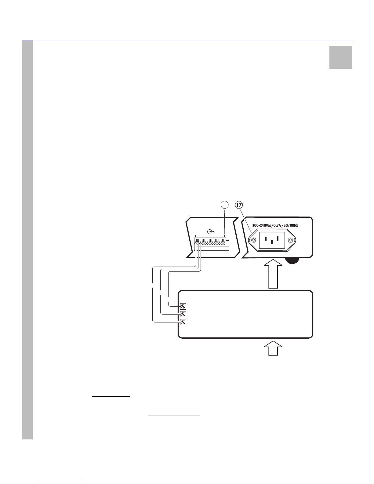
CHAPTER TWO - INSTALLATION
2
For UL/ULC Installations
Mains Supply: 120VAC/60Hz
UPS Output Rating: 120VAC/60Hz, 2.5A. In the USA, use UL listed UPS (uninterrupted power supply) for protective-signalling systems and
listed burglar alarm power supply as applicable. In Canada, connection to an emergency power supply (UPS) with a minimum of 24 hr standby
capacity is required.
For CE Installations
Mains Supply: 240VAC/50Hz
UPS Output Rating (non UL): 240VAC 50Hz
Warning:
To reduce the risk of electrical shock, the SG-System I is equipped with a grounding-type power supply IEC receptacle. Connect SG -System I using an appropriate IEC cable to a grounded receptacle. Connect SG-System I to UPS dry contact connections only. Do not connect
to a receptacle controlled by a switch.
Figure 3: Wiring Diagram
I/O Open Collector, 20 mA (Max)
Use 18-22 AWG (0.5 - 1.0mm) wiring
Not supervised
Power limited
Install the UPS in the same
rack with the receiver or connections shall
be done in the same room and in a protective
metal conduit.
1414
SG-System I Operating Manual
NOTE: Install external devices connected to Items 10~17 in the same room as the SG-System I. Maintain a 6.5mm (1/4”) separation between power limited and non-power limited circuits. All circuits are supervised and power limited with the exception of AC input, which is non-power limited. Maximum cable length is 1.8m (6’). Longer cables may impair performance.
NOTE: F
dance with C22.1, Canadian Electrical Code, Part 1, Safety Standard for Electrical Installations, section 32. This equipment
is intended to utilize the building emergency AC supply system for its standby supply (UPS, batteries in conjunction with
engine-driven generator). Connection to Building Emergency Power Supply (UPS recommended) with a minimum 24hr
standby capability is required. For UL Listed Installations
signalling systems and listed burglar alarm power supplies as applicable.
or ULC Installations
To SG-System I I/O
To SG-System I
IEC grounded receptacle
Pin 1
Pin 2
Pin 3
UPS Low Bat (normally closed)
Common
Connect SG-System I
to UPS dry contact
connections only
For CE Installations For ULC Installations
Main Supply: 240Vac/50Hz Main Supply: 120Vac/60Hz
UPS Output Rating (non UL): UPS Output Rating:
240Vac/50Hz 120Vac/60Hz
, the equipment must be rack mounted and powered by a permanently wired supply in accor-
UPS AC Trouble (normally closed)
From AC Mains
, use UL Listed UPS (Uninterrupted Power Supply) for protective
Non-power limited
AC Out
UPS
AC In
19
Page 27
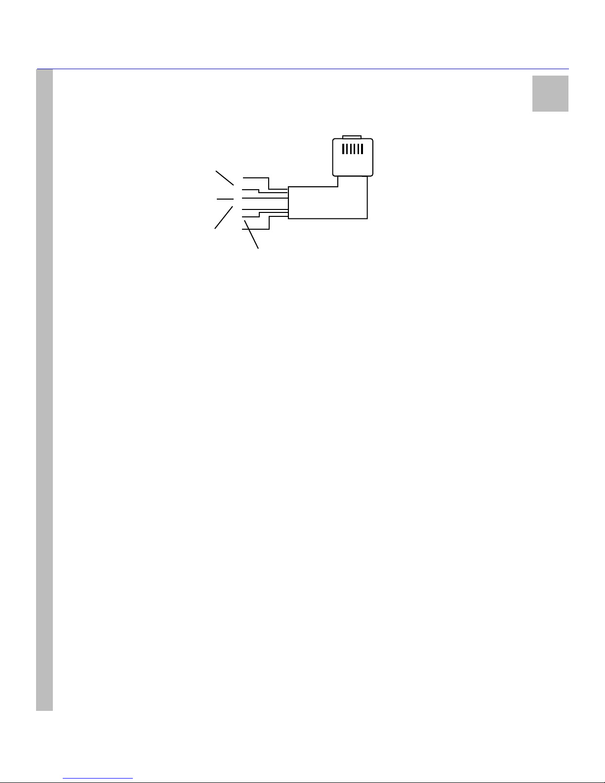
CHAPTER TWO - INSTALLATION
1
2
3
4
5
6
RING Back-up Channel
or 2-way Audio
RING Primary
Channel
TIP Primary
Channel
TIP Back-up Channel
or 2-way Audio
WIRE COLOURS
1 = BLUE
2 = YELLOW
3 = GREEN
4 = RED
5 = BLACK
6 = WHITE
9050
Figure 4: Wiring Diagram for Backup Channel and Two-Way Audio
2
SG-System I Operating Manual
20
Page 28

CHAPTER TWO - INSTALLATION
2
SG-System I Operating Manual
21
Page 29

Operation
In This Chapter...
Operation on page 23
Active Mode on page 23
Manual Mode on page 23
Program Category on page 24
Top Level Menu on page 25
System Functions Menu on page 25
Miscellaneous LED Indicators on page 26
Page 30
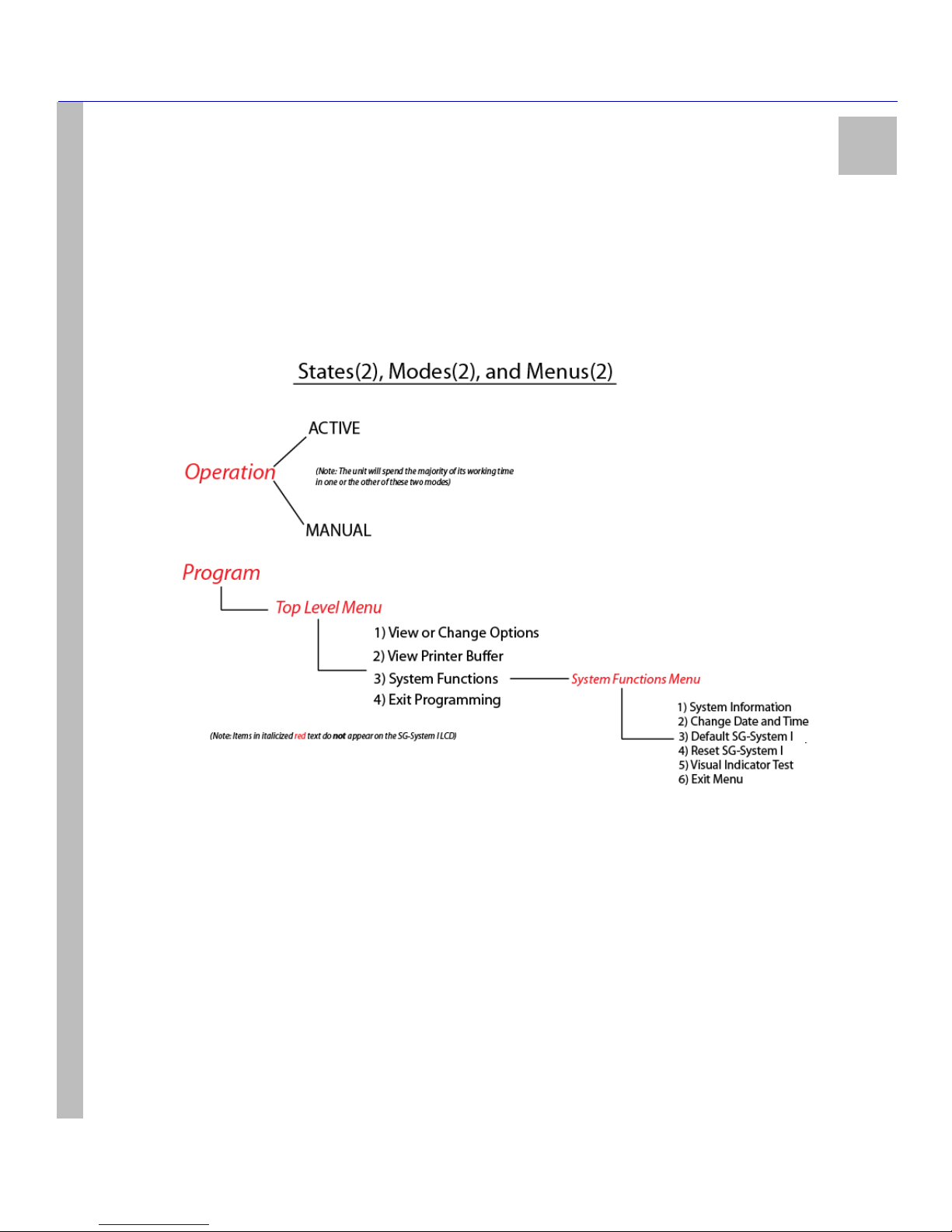
CHAPTER THREE - OPERATION
3
Operation
The SG-System I will occupies one of two states, Operation or Program. Operation consists of Active and Manual modes, in either of
which the system will spend the vast majoirity of its working time. Program consists of the Top Level Menu and the System Functions
Menu. The Top Level menu includes View / Edit Options, View Printer, System Functions and Edit Programming. While in System
Functions you can access the System Functions Menu. This menu includes System Information, Date and Time, Default SG-System I,
Reset SG-System I, User Interface and Exit Menu. See Figure 5: Operating States(2), Modes(2), and Menus(2) immediately below.
Figure 5: Operating States(2), Modes(2), and Menus(2)
SG-System I Operating Manual
Active Mode
Active mode is the most common operating mode. The SG-System I is in Active mode when any of the automation software ports are present
and responding to signals. When there are no incoming calls to the unit, Active mode will give way to Manual mode. On receiving an incoming call, the unit will automatically revert to Active mode.
Manual Mode
Manual mode occurs when automation software is lost or has been programmed out (all automation ports have been disabled). Switching
from Active mode to Manual mode in this case is automatic.
In Manual mode, the SG-System I receives signals and attempts to send the first signal in the buffer. The unit simultaneously displays the
message on the LCD screen, activates the buzzer, and activates the acknowledge LED. To stop the buzzer and the acknowledge LED, the
Ack (Acknowledge) button must be pressed and released for every signal not acknowledged in the buffer. The LCD messages received in
Manual mode are duplicates of the printer messages. For messages greater than 39 characters, the first 39 characters are displayed. Pressing
the Enter button will display the remainder of the message. You are strongly advised to make note of these messages in case any are of a serious nature (e.g. a fire alarm). You must deal with alarms generated while the system is in Manual mode. It is imperative that time spent by the
system in Manual mode must be kept to a strict minimum. Note that the alarm printer and automation buffers reside in the SG-System I.
23
Page 31
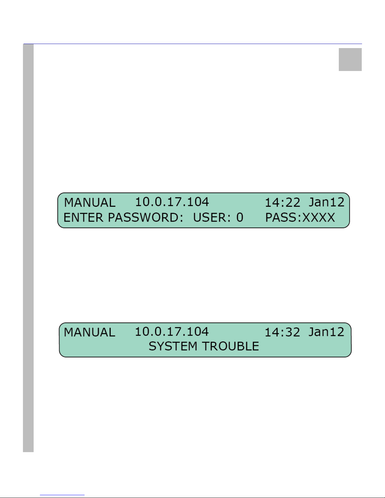
CHAPTER THREE - OPERATION
Program Category
The Program category is accessed in order to program the SG-System I or to view its condition. Sixteen users in total can have access to the
unit. User ‘0’ is the Administrator, and has full permissions with regard to using and configuring the unit. All other users - ‘1~F’ - may view
system information only, in addition to having the ability to change the time and date displayed on the LCD.
NOTE: All alarms must be acknowledged via the Ack button before entering Program mode from Manual
mode.
Password
A password must be entered before the Program category can be accessed. Take the following steps:
1. Press the Enter button while the unit is in either of the Operation modes (Active / Manual) to call up the password field.
2. Enter your 4-digit hexadecimal password on the bottom line (use the Up and Down arrow buttons to scroll through the characters).
Note that the default password is ‘CAFE’.
3. Press the Enter button to select the desired value and move along to the next digit.
4. Continue until the four spaces are filled. Pressing the Enter button after selecting the fourth digit will automatically present the password to the system for acceptance / rejection.
3
Assuming that the password is correct, the SG-System I will enter Program category and generate the corresponding printer and automation
signals. Should the password be incorrect, the unit will produce an error tone and return to a Base category (Active mode or Manual mode).
Press the Enter button once more to return to the Password screen.
The password can be set in the following manner:
1. Enter the Program category.
2. Scroll to View or Change Options > CPM Options > Option 006.
3. Scroll to the user whose password is to be changed. Enter the new password. Press the Enter button. The new password is set.
SG-System I Operating Manual
User Interface
The SG-System I unit’s LCD and button interface give the user the ability to program the unit and scroll through the printer buffer and the
trouble list. The upper line displays the device mode (in the example below, ‘MANUAL’). The lower line displays the system information
(in the example below, ‘SYSTEM TROUBLE’).
24
Page 32
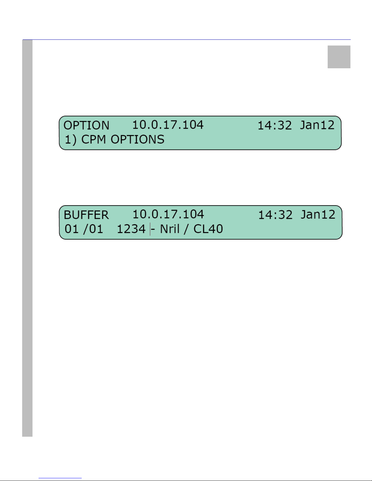
CHAPTER THREE - OPERATION
3
Top Level Menu
View or Change Options
In View or Change Options, use the Up and Down arrow buttons to locate the configurable option categories. These categories are: CPM
Options / Channel-1 Options / Channel-2 Options / Channel-IP Options / Exit Menu. Please refer to Chapter 4 for a detailed list of the system
options available within each category.
Select the Exit Menu and press the Enter button. You will return to the View or Change Options level. Pressing the Up and Down buttons
simultaneously - regardless of your place within View or Change Options - will take you to the Top Level menu.
View Printer Buffer
The bottom line of the LCD is cleared when View Printer Buffer is entered. The oldest message in the buffer, including those that have been
acknowledged, will be displayed first. Use the Up button to review the older messages and the Down button to review the newer messages.
In the case of a lengthy message, the first 39 characters will be displayed. Press the Enter button to show the remainder of the message. This
view is available only in Manual mode to review acknowledge messages.
Pressing the Up and Down buttons simultaneously to go to the Top Level menu.
System Functions
System Functions provides access to the System Functions Menu, which consists of System Information / Change Date and Time / Default
SG-System I / Reset SG-System I / Visual Indicator Test / Exit Menu.
SG-System I Operating Manual
Exit Programming
Pressing the Enter button while in Exit Programming will take the user back to the Active mode or the Manual mode.
System Functions Menu
System Information
System Information provides a wealth of detail regarding the user’s setup of SG-System I. These details include:
•Version
•ID
• LAN MAC
• LAN IP
• Gateway IP
•SW Checksum
• VHDL Version
• DSP Checksum
• DSP Version
• Manufacture Date
• Country of Manufacture Code
•AHS Table
25
Page 33
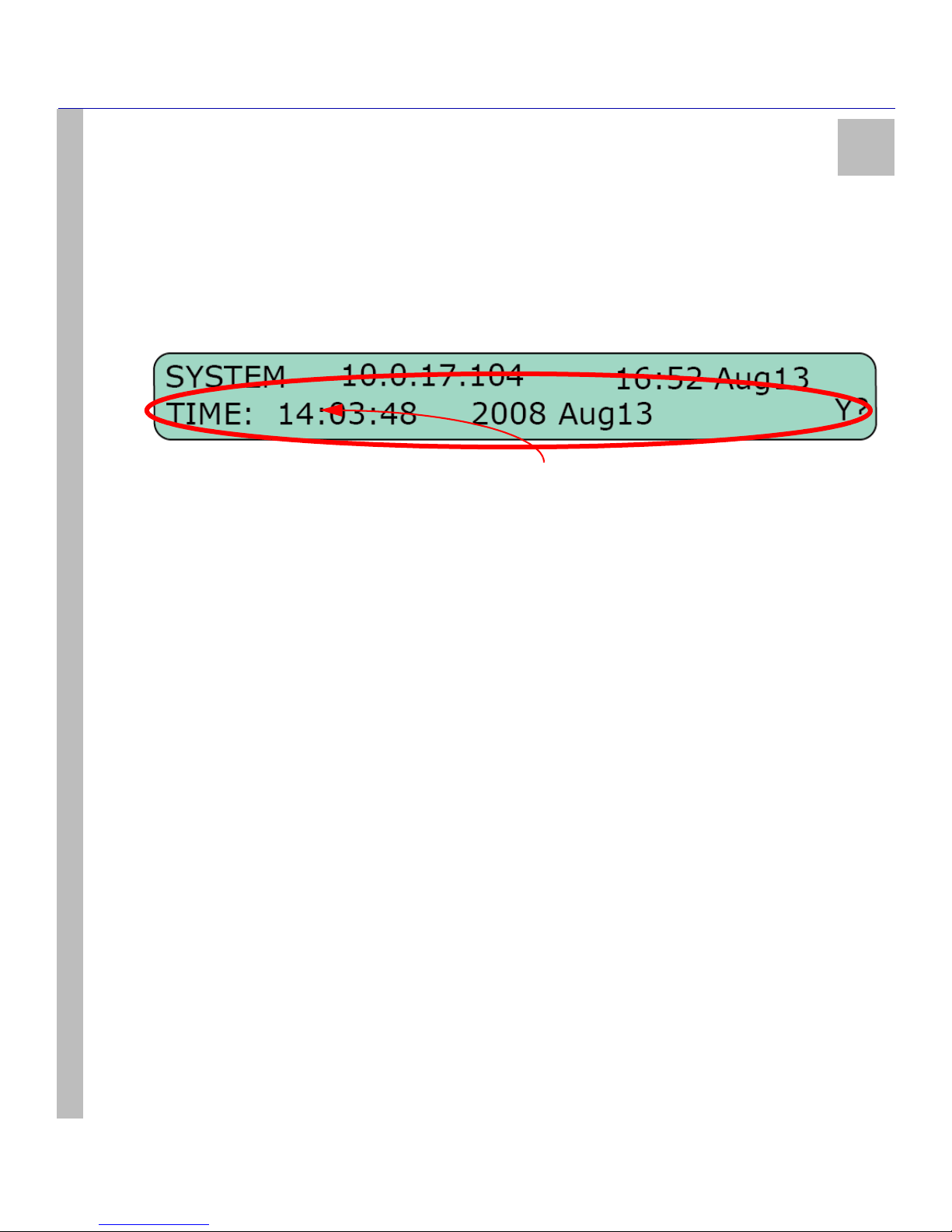
CHAPTER THREE - OPERATION
• IP Accounts
NOTE: The number in parentheses represents the number of times the value has been changed or the size of a particular
table.
To return to System Information while viewing any of the above, press the Up and Down buttons simultaneously. Pressing the Up and Down
buttoms once more will take you to the Top Level menu.
Change Date and Time
Having chosen to enter Change Date and Time by pressing the Enter button, the unit’s LCD appears as below:
1. Changes to the time and date begin at the far left of the screen with the hour, and proceed to the right. The Up button will increase the
value of the digit; the Down button will decrease its value.
2. Having made a change, press the Enter button to advance to the next digit on the right. Pressing the Enter button without having
made any changes will also move the cursor to the next digit on the right.
3. Once the Day has been entered and the Enter button pressed, the user will be asked by the SG-System I to confirm the changes: N?
for no; Y? for yes. Use the Up and Down buttons to navigate between yes and no.
4. Press the Enter button to save your changes.
3
NOTE: At any point before the time and date have been saved, pressing the Up and Down buttons simultaneously will cancel any unsaved changes and return the user to the System Functions Menu.
Default SG-System I
When Default SG-System I is selected, the LCD will prompt the user to confirm that the entire system is to be returned to its default values.
Selecting Y? for yes will default the system; selecting N? for no will leave system settings as they are. Either of the Up and Down buttons
can be used to cycle between answers.
SG-System I Operating Manual
Reset SG-System I
When Default SG-System I is selected, the LCD will prompt the user to confirm that the entire system is to be reset. This action may be
taken to enable a programming change, or to restore an ailing system to working order. Selecting Y? for yes will reset the system; selecting
N? for no will leave the system as it is. Either of the Up and Down buttons can be used to cycle between answers.
Visual Indicator Test
Selecting the Visual Indicator Test turns on all of the LCD pixels and the unit’s buzzer, to confirm that they are in good working order.
Exit Menu
When in Top Level Menu > Exit Menu, pressing the Enter button will take the user back one level to the Base (Active mode or Manual
mode) level. When in System Functions Menu > Exit Menu, pressing the Enter button will take the user back one level to Top Le v e l
Menu > System Functions. While in System Functions, navigate to Exit Programming. Pressing the Enter button will take the user back to
the Base (Active mode or Manual mode) level.
Miscellaneous LED Indicators
View Trouble
To enter View Trouble, the unit must first be in Active mode or Manual mode, and have no events to be acknowledged in Manual mode.
Press the Up and Down buttons simultaneously to enter View Trouble. Once there, the Up and Down buttons can be used to review the list of
26
Page 34
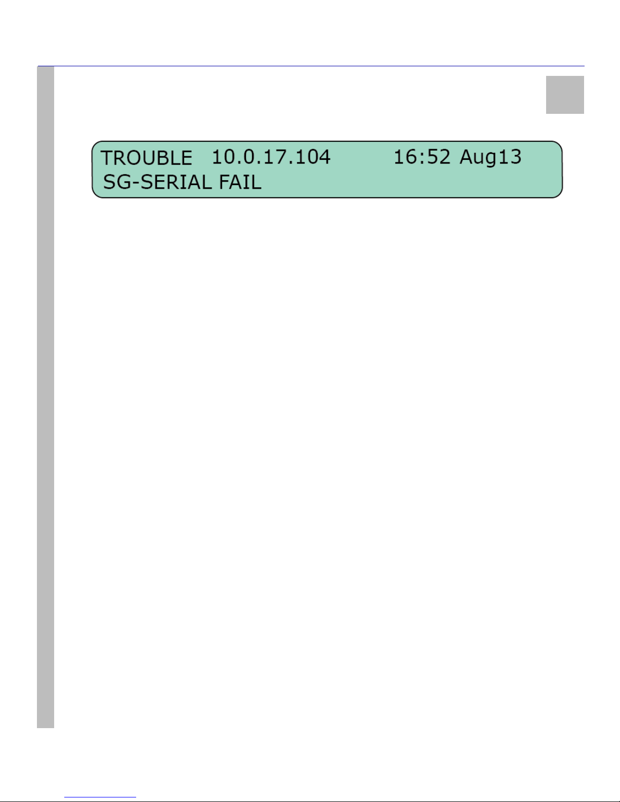
CHAPTER THREE - OPERATION
3
troubles. Should there be no troubles, the LCD will flash NO TROUBLE for a few seconds and return to the previous level of operation. A
list of possible troubles can be found below.
Trouble List
The following trouble and status lists are monitored by the system. Individual troubles can be disabled in the Program category. Both the
trouble list and the status list are fully enabled by default.
Trouble:
• Parallel Printer
• Serial Printer
•TCP Printer
• USB Printer
• Serial Automation
• TCP Automation
• UPS Battery
• UPS AC
• DSP Failed Ch1
• DSP Failed Ch2
Status:
• Line Fault - Channel 1
• Line Fault - Channel 2
• System Absent - Channel 1
•Clock Not Set
•Printer Buffer Full
SG-System I Operating Manual
• Checksum Failed - Software
• DSP Checksum Failed
View Network / Watchdog
Please refer to Set Up and Testing on page 18 for detailed Network information.
View Status
Please refer to Set Up and Testing on page 18 for detailed Status information.
27
Page 35
Options: System
In This Chapter...
System Option Index on page 29
Steps required to access an option and change its setting or value on
page 29
System Options on page 30
Page 36

System Option Index
Option 001: LAN IP Address on page 30
Option 002: LAN Subnet Mask Address on page 30
Option 003: LAN Gateway on page 30
Option 004: Auto Update Time and Date on page 30
Option 005: Contrast on page 30
Option 006: Password on page 31
Option 007: Automation Baud Rate on page 31
Option 008: Automation Data Bits on page 31
Option 009: Automation Parity on page 32
Option 00A: Serial Printer Format on page 32
Option 00B: Serial Baud Rate on page 32
Option 00C: Serial Data Bits on page 32
Option 00D: Serial Printer Parity on page 33
Option 00E: AHS Operations Time on page 33
Option 00F: B32 Headers on page 33
Option 012: Heartbeat Timer on page 33
Option 013: Buzzer Tone on page 34
Option 014: Receiver Number on page 34
Option 015: Printer Test on page 34
Option 020: Mask UPS AC on page 35
Option 021: Mask UPS BAT on page 35
CHAPTER FOUR - OPTIONS: SYSTEM
4
Option 024: Mask SG TCP/IP on page 35
Option 025: Mask SG Serial on page 35
Option 028: Mask TCP Printer on page 35
Option 029: Mask Parallel Printer on page 36
Option 02A: Mask Serial Printer on page 36
Option 02F: Automation Mode on page 36
Option 030: Printer Mode on page 37
Option 031: ACK Wait on page 38
Option 032: Date Format on page 39
Options 037 and 038: License Keys #1, #2 on page 39
Option 039: Mask USB Printer on page 39
Option 03A: Programmable I/O on page 39
Option 03B: Last Message On on page 40
Option 03C: LCD Backlight Colour on page 40
Option 03D: Key Backlight Colour on page 40
Option 040: Number of Channels on page 41
Option 041: System Number Length on page 41
Option 042: Busy Out on page 42
Option 043: System Protocol ID on page 42
Option 044: System CLASS Field on page 43
Steps required to access an option and change its setting or value
The steps required to access an option and change its setting or value are very nearly uniform from option to option. The procedure detailed
below will match satisfy the majority of options. Those it does not will accept close, intuitive variations of it. Please refer to the steps below
when programming system options.
To change an option’s setting or value, take the following steps:
SG-System I Operating Manual
1. Turn on the SG-System I.
2. Use the Up and Down buttons to select the user. User ‘0’ has full administrative powers; all other users may only review system set-
tings, in addition to changing the time and date.
3. Press the Enter button. This initiates the password sequence, placing a flashing cursor underneath the first digit of the four-digit password.
4. Use the Up and Down buttons to select the appropriate value. Press the Enter button. The cursor will advance to the next digit.
5. Repeat Step 4 for all four digits. If the password you have entered is correct, you now have access to SG-System I. If not, re-enter
your password.
6. View or Change Options appears on the LCD. Press the Enter button.
7. Use the Up and Down buttons to locate which section of options is valid for your configuration of SG-System I: CPM Options /
Channel-1 Options / Channel-2 Options / Channel-IP Options / Exit Menu.
8. Press the Enter button. The options applicable to your system are to available for you to access.
9. Navigate to Option XXX. Press the Enter button. The current value is displayed on the LCD.
10. Press the Enter button. The value may now be changed.
11. Use the Up or Down buttons to scroll to the desired value.
12. Having made a selection, press the Enter button.
13. The LCD will prompt you to accept (Y?) or to decline (N?) your changes.
14. Use the Up and Down buttons to select your response. Press the Enter button.
15. Your changes have been saved.
29
Page 37

CHAPTER FOUR - OPTIONS: SYSTEM
System Options
Option 001: LAN IP Address
Default (10.0.7.200)
Enter the IP address of the SG-System I. The IP address must be entered as a dotted decimal number (e.g. 255.255.001.000). Each threedigit segment of the IP address must be within a valid range of 000 to 255.
NOTE: The SG-System I must be restarted for these changes to take effect.
Option 002: LAN Subnet Mask Address
Default (255.255.0.0)
Enter the LAN Subnet Mask address of the SG-System I. The address must be entered as a dotted decimal number (e.g. 255.255.001.000).
Each three-digit segment of the address must be within a valid range of 000 to 255.
NOTE: The SG-System I must be restarted for these changes to take effect.
4
Option 003: LAN Gateway
Default (0.0.0.0)
Enter the LAN Gateway address of the SG-System I. Take care to ensure that the address is unique to your system. The address must be
entered as a dotted decimal number (e.g. 255.255.001.000). Each three-digit segment of the address must be within a valid range of 000 to
255. The gateway is used in the event that the data being sent is not on the same network as the SG-System I. The data will need to be sent
through a router device. This is the address of that router device.
NOTE: The SG-System I must be restarted for these changes to take effect.
SG-System I Operating Manual
Option 004: Auto Update Time and Date
Default (0)
This option enables the automation to update the SG-System I’s time via the TCP/IP port. If the SG-System I fails to get the time and date
within a twenty-four-hour period (started after the last update is received), it will generate a status message to the printer and automation,
following the internal trouble protocol. The Trouble status on the SG-System I display will not be affected.
Printer message: “Time&Date Update Fail”
Automation message: [#0000|NRU0000]
Option 005: Contrast
Default (80)
Use this option to adjust the level of contrast of the unit’s LCD. Pressing the Up button will increase the contrast, while pressing the Down
button will decrease the contrast. Alternatively, pressing the Up and Enter buttons simultaneously will increase the level of contrast; pressing
the Down and Enter buttons simultaneously will decrease the level of contrast. Contrast can be adjusted in both Active and Manual modes.
30
Page 38

CHAPTER FOUR - OPTIONS: SYSTEM
4
Option 006: Password
Default (CAFE)
Use this option to change or delete SG-System I users and their passwords. Sixteen users with 4-digit passwords are available for use on the
SG-System I. User 0 is the Master user, with complete administrative control over the system. Users 1 through F may be assigned to individuals within your organization; these sixteen users are able to review system settings but not change them, with the exception of the Time and
Date. To delete a user, program the password for that user to ‘FFFF’.
NOTE: User 0 can not be deleted.
To change your password, take the following steps:
1. Navigate to Option 006.
2. Press the Enter button. The user designation (e.g. ‘0’, ‘F’) is displayed, in addition to the current password in the form of ‘XXXX’.
3. Press the Enter button to begin the process of changing the password.
4. Use the Up and Down buttons to make your selection and press the Enter button. The cursor advances to the next digit.
5. On selecting the fourth digit and pressing the Enter button, the unit LCD will will prompt you to accept (Y?) or to decline (N?) your
changes.
6. Press the Enter button again to accept or to decline your changes.
Option 007: Automation Baud Rate
Default (9600)
This option determines the baud rate at which the SG-System I will communicate to the automation software via serial port 1. As a general
rule, the faster the baud rate, the better the unit’s performance. Older automation software packages can not, however, manage a fast baud
rate and will require a slower baud rate in order to perform at an optimal level. Valid selections are: 1200, 2400, 4800, 9600, 19200, 38400,
and 57600.
NOTE: The SG-System I must be restarted for these changes to take effect.
SG-System I Operating Manual
Option 008: Automation Data Bits
Default (8)
This option determines the number of data bits the SG-System I will use to communicate to the automation software via serial port 1. Valid
selections are seven or eight, to indicate seven data bits or eight data bits. As a general rule, the higher the number of data bits, the better the
unit’s performance.
NOTE: The SG-System I must be restarted for these changes to take effect.
31
Page 39

CHAPTER FOUR - OPTIONS: SYSTEM
Option 009: Automation Parity
Default (0)
This option determines the parity of serial port 1.
NOTE: The number of stop bits can not be changed and will always be 2.
NOTE: The SG-System I must be restarted for these changes to take effect.
4
Table 5: Automation Parity
Value Degree of Parity
0No parity
1 Odd parity
2 Even parity
Option 00A: Serial Printer Format
Default (0)
This option regulates how data is formatted when sent to a serial printer and how the serial port is supervised. By setting Option 00A to 01,
CTS will need to be set high and print to both HyperTerminal and physical serial printer. By setting Option 00A to 02 (note that this will be
displayed as ‘DCD’ in programming mode), DCD will need to be set high. This option affects how the COM2 serial port is supervised and
how the data is formatted. The default value disables the option, blocking the printing of data.
NOTE: The SG-System I must be restarted for these changes to take effect.
Option 00B: Serial Baud Rate
Default (57600)
SG-System I Operating Manual
This option determines the baud rate at which the SG-System I will communicate to the serial printer via serial port 2. As a general rule, the
faster the baud rate, the better the unit’s performance. Valid selections are: 1200, 2400, 4800, 9600, 19200, 38400, and 57600.
NOTE: The SG-System I must be restarted for these changes to take effect.
Option 00C: Serial Data Bits
Default (8)
This option determines the number of data bits the SG-System I will use to communicate to the serial printer via serial port 2. Valid selections are seven or eight, to indicate seven data bits or eight data bits. As a general rule, the higher the number of data bits, the better the unit’s
performance.
NOTE: The SG-System I must be restarted for these changes to take effect.
32
Page 40

CHAPTER FOUR - OPTIONS: SYSTEM
4
Option 00D: Serial Printer Parity
Default (0)
This option determines the parity of serial port 2. ‘0’ represents no parity, ‘1’ represent odd parity, and ‘2’ represent even parity.
NOTE: The number of stop bits can not be changed and will always be 2.
NOTE: The SG-System I must be restarted for these changes to take effect
Option 00E: AHS Operations Time
Default (24)
Use this option to program at what time the AHS table will be saved to Flash. Backup will occur once every twenty-four-hours at the stated
time. When the backup operation is in progress a status message will appear on the LCD, above the time and date. A text message will be
sent to the printer when AHS backup starts, stops, or fails.
To set the time - on the hour - at which AHS backup will take place each day, take the following steps:
1. Navigate to Option 00E and press the Enter button.
2. The LCD will, if Option 00E has not previously been altered, mark the option’s status as ‘OFF’. Use the Up and Down buttons to
scroll to a time of day.
3. Select a time of day that you would like AHS backup to begin and press the Enter button. The unit will prompt you to save (Y?) or
decline (N?) your changes. Make the appropriate choice and press the Enter button.
Option 00F: B32 Headers
Default (00)
This option enables compatibility with MAS B32 Automation Software through TCP/IP. To enable this option, change the value to ‘01’.
NOTE: The SG-System I must be restarted for these changes to take effect
SG-System I Operating Manual
Option 012: Heartbeat Timer
Default (30)
Use this option to determine the time interval - measured in seconds - the heartbeat transmission is sent to Serial Automation and TCP/IP
port 1025. The heartbeat times is used to ensure that any communication through Serial Automation and TCP/IP is functioning normally
when there is no traffic from the receiver. Note that any traffic from the receiver will reset the heartbeat timer. Therefore, the heartbeat transmission will be sent only if there is no signal sent during the time specified in Option 012.
33
Page 41

CHAPTER FOUR - OPTIONS: SYSTEM
Option 013: Buzzer Tone
Default (00)
A tone will sound when the SG-System I, having received an alarm, is unable to forward the alarm message to either the Serial or TCP/IP
automation paths (while in Manual mode). You are able to manipulate this tone via Option 013. The tone generated will continue to pulse
until all unacknowledged events have been acknowledged by the user; this can be done by pressing the Ack button for each event, or the unit
itself transfers from Manual mode to Active mode. If Option 013 is set to ‘0’ or ‘1’, no buzzer tone will sound on receipt of an alarm. Any
other value will produce a tone.
4
Table 6: Buzzer Tones
IDX Frequency (Hz)
20 1490
25 1990
26 2103
30 2650
33 3149
37 3965
38 4270
39 4530
To set the buzzer tone, take the following steps:
1. Navigate to Option 013. Press the Enter button. The current value is displayed on the LCD.
SG-System I Operating Manual
2. Press the Enter button. The value may now be changed.
3. Use the Up and Down buttons to scroll to the desired value.
NOTE: As each tone is selected the SG-system I will sound that tone for a period of 250 msec, allowing the user the opportunity to judge each tone as it is selected.
4. Having made a selection, press the Enter button.
5. The LCD will prompt you to accept (Y?) or to decline (N?) your changes.
6. Use the Up and Down buttons to select your answer. Press the Enter button.
NOTE: Refer to UL864 Programming Requirements on page 10 if changing the default setting.
Option 014: Receiver Number
Default (01)
The receiver number is used to identify the receiver (or, unit) when communicating to the TCP/IP Automation, the Serial Automation, and
any connected printer. This receiver number applies to all traffic, unless overridden by another option. In the event that such overriding takes
place, it will most likely be a Fallback / Recovery Strategy option.
Option 015: Printer Test
Default (ON)
When this option is enabled, a test signal is sent to all active printers at 0500 hrs and 1700 hrs of every day.
34
Page 42

CHAPTER FOUR - OPTIONS: SYSTEM
Sample printer message: 26 Nov 2003 16:41:25 - 26 Nov 2003-16:41:25-00/00-SG-01-000-0000--Printer Test Message
Option 020: Mask UPS AC
Default (ON)
Use this option to enable the UPS AC Shelf 1 trouble mask. If enabled, trouble conditions are not reported.
OFF - Condition reported
ON - Condition not reported (masked)
NOTE: Refer to UL864 Programming Requirements on page 10 if changing the default setting.
Option 021: Mask UPS BAT
Default (ON)
Use this option to enable the UPS Battery Shelf 1 trouble mask. If enabled, trouble conditions are not reported.
OFF - Condition reported
ON - Condition not reported (masked)
4
NOTE: Refer to UL864 Programming Requirements on page 10 if changing the default setting.
Option 024: Mask SG TCP/IP
Default (OFF)
Use this option to enable the SG TCP/IP trouble mask. If enabled, trouble conditions are not reported.
OFF - Condition reported
ON - Condition not reported (masked)
NOTE: Refer to UL864 Programming Requirements on page 10 if changing the default setting.
SG-System I Operating Manual
Option 025: Mask SG Serial
Default (OFF)
Use this option to enable the SG Serial trouble mask. If enabled, trouble conditions are not reported.
OFF - Condition reported
ON - Condition not reported (masked)
See UL864 Programming Requirements on page 10.
Option 028: Mask TCP Printer
Default (OFF)
Use this option to enable the TCP Printer trouble mask. If enabled, trouble conditions are not reported.
OFF - Condition reported
ON - Condition not reported (masked)
See UL864 Programming Requirements on page 10.
35
Page 43

CHAPTER FOUR - OPTIONS: SYSTEM
Option 029: Mask Parallel Printer
Default (OFF)
Use this option to enable the Parallel Printer trouble mask. If enabled, trouble conditions are not reported.
OFF - Condition reported
ON - Condition not reported (masked)
NOTE: Refer to UL864 Programming Requirements on page 10 if changing the default setting.
Option 02A: Mask Serial Printer
Default (OFF)
Use this option to enable the Serial Printer trouble mask. If enabled, trouble conditions are not reported.
OFF - Condition reported
ON - Condition not reported (masked)
NOTE: Refer to UL864 Programming Requirements on page 10 if changing the default setting.
4
Option 02F: Automation Mode
Default - Fallback (01)
The TCP/IP connection is the primary output of the SG-System I for automation computer alarms. It is expected that sockets may appear and
disappear regularly as processes are terminated and reconstituted. After five seconds of socket loss, a socket loss is declared and automation
output is shifted to the next connection level, which is the serial automation output connection. There are five levels of automation:
Loop (00)
At startup, the SG-System I will send to the TCP/IP until it fails, proceed to the RS232 until it fails, proceed back to the TCP/IP
until it fails, and so on. Please refer to the Automation Mode workflow diagrams below.
SG-System I Operating Manual
Fallback (01)
NOTE: This value will not generate an automation absent message.
If both outputs are present, the system will send to the TCP/IP connection until it fails, proceeding next to the RS232 connection.
It will continue to send to the serial connection without stop, or until the reset fallback command is generated from the console, in
which case it will re-try the TCP/IP connection. Please refer to the Automation Mode workflow diagrams below.
Automatic IP Fallback (04)
This mode is similar to Fallback, save that when the TCP/IP connection is restored the SG-System I will return to the TCP/IP port
to send events. This eliminates the need for the Reset SG Fallback from the SG-System I Console. Please refer to the Automation
Mode workflow diagrams below.
NOTE: The SG System I must be restarted for these changes to take effect.
36
Page 44
Figure 6: Loop (00), Automatic IP Fallback (04)
Power Up /
Restart
SG-System I TCP
Port Active?
\SG-System I
Serial 1 P ort
Active?
Poll
Automation
Manual Re - st art
from C onsol e
(Res et F allback )
Manual Re - st art
from C onsol e
(Res et F allback )
NO
YES
NO
Automa tic F alback
mode (4 )
Power Up /
Restart
SG-System I Port
Active?
SG-System I Serial
1 Port Ac tive?
Poll
Automation
Manual Re-start
fr om C ons ole
(R ese t Fallbac k)
Manual Re-start
fr om C ons ole
(R ese t Fallbac k)
NO
YES
NO
CHAPTER FOUR - OPTIONS: SYSTEM
4
Figure 7: Fallback (01)
SG-System I Operating Manual
Option 030: Printer Mode
Default (LOOP)
You can configure this option with an approach similar to the automation outputs of Option 02F above, except that Fallback (01) and Automatic IP Fallback (04) are not available. Acceptable values are Loop (00) or All (02). Note that Loop (00) transmits printer messages to each
port in turn. The first port to respond will be used to process subsequent printer messages until it is no longer able to do so, at which point the
next port in the loop will be employed. All (02) transmits printer messages to all ports simultaneously.
37
Page 45
CHAPTER FOUR - OPTIONS: SYSTEM
Power Up /
Restart
SG-System I TCP
Port Active?
SG-Sys tem I Serial
1 Port Active?
Poll
Automation
YES
YES
NO
NO
Figure 8: All (02)
4
NOTE: The order of sequence is: TCP, Parallel, USB, and Serial. DSC does not recommend changing the default setting
unless using more than one printer.
NOTE: The SG System I must be restarted for these changes to take effect.
NOTE: Refer to UL864 Programming Requirements on page 10 if changing the default setting.
To set the printer mode, take the following steps:
1. Navigate to Option 030. Press the Enter button. The current value is displayed on the LCD.
2. Press the Enter button. The value may now be changed.
3. Use the Up or Down buttons to scroll to the desired value. Select an integer value from 40 to 99, representing 4.0 seconds to 9.9 seconds. For example, 63 would represent a value of 6.3 seconds.
4. Having made a selection, press the Enter button.
SG-System I Operating Manual
5. The LCD will prompt you to accept (Y?) or to decline (N?) your changes.
6. Use the Up and Down buttons to select your response. Press the Enter button.
NOTE: The SG System I must be restarted for these changes to take effect.
Option 031: ACK Wait
Default (40)
Use this option to determine the acknowledgement wait time, measured in tenths of a second, during which the SG-System I will wait for a
response to automation software outputs. If none is received during this interval, the automation software output is retransmitted and the
timer reset.
38
Page 46
CHAPTER FOUR - OPTIONS: SYSTEM
Option 032: Date Format
Default (DD/MM/YYYY)
Use this option to determine the format of the date for printer output. Valid entries are 0 and 1.
Table 7: Date Format
Value Output
(0) International DD / MM / YYYY
(1) US MM / DD / YYYY
NOTE: The SG System I must be restarted for these changes to take effect.
Options 037 and 038: License Keys #1, #2
The License Key #1 option allows the user to enter a key that will enable IP Channel functionality on the SG-System I.
The License Key #2 option allows the user to enter a key that will enable distinct sellable features on the SG-System I.
NOTE: Both keys are required to unlock the IP function.
4
To enter the license keys, take the following steps:
1. Navigate to Option 037/038. Press the Enter button. The current value is displayed on the LCD.
2. Press the Enter button. The value may now be changed.
3. Use the Up or Down buttons to scroll to the desired value.
4. Having made a selection, press the Enter button. The cursor will advance to the next digit.
5. Repeat Steps 3 and 4 until the full license key has been entered.
6. The LCD will prompt you to accept (Y?) or to decline (N?) your changes.
7. Use the Up and Down buttons to select your response. Press the Enter button.
SG-System I Operating Manual
NOTE: If you enter a license key that is incorrect, the receiver will send a ‘Invalid License Key’ message to the printer. A correct license key will generate no message at all.
Option 039: Mask USB Printer
Default (ON)
Use this option to enable the USB Printer mask. If enabled, trouble conditions are not reported.
OFF - Condition reported
ON - Condition not reported (masked)
NOTE: Refer to UL864 Programming Requirements on page 10 if changing the default setting.
Option 03A: Programmable I/O
Default (00)
NOTE: SG-System I version 1.0 has the inputs and outputs hard set. Later versions will permit user access to unit inputs
and outputs.
I/O interface connections are located at the back of the unit and employ a screwless, spring-type terminal. There are three outputs and four
inputs on the unit. Relays are employed for the output switching of the SG-System I unit. I/O functions are described at item 14 of the Tab le
3: SG-System I Front and Rear Panel Descriptions on page 15.
39
Page 47

CHAPTER FOUR - OPTIONS: SYSTEM
Option 03B: Last Message On
Default (Off)
When enabled, this option displays the most recent printer message on the lower line of the unit LCD. It will remain there until a new printer
message replaces it. The automation condition - e.g. mode (Active / Manual) or slot (all / TCP / Serial) - does not have any effect on this feature.
Option 03C: LCD Backlight Colour
Default (Cyan)
You can use this option to select the LCD backlight colour. Available colours are: OFF / WHITE / GREEN / BLUE / MAGENTA / CYAN /
ORANGE / PURPLE / AQUA / PINK / ROYAL / FADE / CYCLE.
When accessing this option, the available colours will appear on the LCD as you cycle through them, providing a preview of their effect.
This is done without your needing to exit the menu.
Colour Description
4
Table 8: LCD Backlight Colour
Off Light grey.
White ~ Royal As per its name.
Fade A static blend of all available colours from white to royal.
Cycle Rotates through all available colours from white to royal at one second intervals.
Yellow Reserved for Trouble mode.
Red Reserved for Manual mode.
SG-System I Operating Manual
Option 03D: Key Backlight Colour
Default (Cyan)
You can use this option to select the LCD backlight colour. Available colours are: OFF / WHITE / GREEN / BLUE / MAGENTA / CYAN /
ORANGE / PURPLE / AQUA / PINK / ROYAL / FADE / CYCLE.
When accessing this option, the available colours will appear on the LCD as you cycle through them, providing a preview of their effect.
This is done without your needing to exit the menu.
NOTE: Please refer to Table 8: LCD Backlight Colour on page 40.
40
Page 48
CHAPTER FOUR - OPTIONS: SYSTEM
Option 040: Number of Channels
Default (C1+C2)
Use this option to determine the number of channels to be polled by the SG-System I. Valid entries range from 01~05.
Table 9: Number of Channels
Number of channels Description UL864
4
C1 Only one channel of POTS is used. All reporting of trouble / status conditions for the sec-
ond line will be masked and the channel will be indicated as busy.
C1 + C2 Both POTS hcannels are used. No IP communication will be possible with this setting.
The Alarm port will be indicated as busy. Trouble / status conditions will be masked for
the IP channel.
C1 + C2 + IP Both POTS channels and the IP channel will be polled. IP functions will be available
only if they have first been unlocked.
C1 + IP One POTS channel and the IP channel will be polled. IP functions will be available only
if they have first been unlocked. All reporting of trouble / status conditions for the second
line will be masked and the channel will be indicated as busy.
NOTE: Refer to UL864 Programming Requirements on page 10 if changing the default setting.
Option 041: System Number Length
Default (0A)
Use this option to determine how many digits from the line card number will be sent to the output. You can make the option display these
digits in hexadecimal or decimal. In a small environment with a limited number of receivers, the default value will suffice. In a large environment with a large number of receivers, this option provides useful flexibility. Possible values are listed in the table below.
SG-System I Operating Manual
Table 10: System Number Length
Value Description
-
UL
UL
UL
01 Sends a one digit hexadecimal number to the printer or computer output (a two-digit line card number will have only
the first digit sent to the output). If using DNIS, replace with RRLLL. The output will now be three digits of RRL.
02 Sends a two-digit hexadecimal line card number to the output. If using DNIS, replace with RRLLL. The output will
03 Sends a three-digit hexadecimal line card number to the output (leading zeroes will be inserted as a suffix to the line
card number). If using DNIS, replace with RRLLL. The output will now be five digits of RRL.
0A Sends a three-digit line card number as entered (no conversion). If using DNIS, replace with RRLLL. The output will
0D Sends a three-digit line card number in decimal (conversion from hexadecimal to decimal). If using DNIS, replace with
NOTE: This option should always correspond to the number of DNIS digits being received. E.g. If five digits are being
received, this option should be set to three. This will force the five digits of DNIS DDDDD to overwrite the standard RRLLL.
41
now be four digits of RRL.
now be five digits of RRL.
RRLLL. The output will now be five digits of RRL.
Page 49

CHAPTER FOUR - OPTIONS: SYSTEM
Option 042: Busy Out
Default (00)
Enabling this option allows the line card to seize the phone line in case of a checksum error after download or when its internal buffer is full
after a loss of communication with the system.
• 00 - the line is seized if either of the conditions mentioned above occur.
• 01 - the line is not seized if either of the conditions mentioned above occur.
• 04 - the line will be seized immediately if the automation computer is absent.
• 05 - the line will be seized immediately if the automation computer is absent or there is no communication with the system, but only if
the internal computer (automation) buffer is full. If there is a loss of a printer(s) and the printer buffer is also full, any new alarms will
not be buffered in the internal printer buffer. The SG-System I has two independent buffers, computer and printer.
NOTE: If this option is set to 01, the line card will not buffer any new alarms once the internal buffer is filled. Setting option
042 to this value is not recommended.
NOTE: Refer to UL864 Programming Requirements on page 10 if changing the default setting.
Option 043: System Protocol ID
Default (0)
4
Use this option to ensure that your automation software performs as desired.
NOTE: Note that some automation software packages expect the ‘0’ format, while other automation software packages
expect the ‘S’ format.
RS-232 Format
S,0 (zero): protocol number
RR: Receiver number
LLL: Line number
AAAA: Account code, always 0000
Nxxyy = SIA event
SG-System I Operating Manual
[00] - Output for all internal signals is SRRL protocol.
SRRLLL[#AAAA|Nxxyy]
[01] - Output for all internal signals is 0RRL (Zero) protocol.
0RRLLL[#AAAA|Nxxyy]
[02] - Output signals in automation protocol SRRL with leading space in the zone (DVACS only).
[03] - Output signals in automation protocol 0RRL (zero) with leading space in the zone (DVACS only).
42
Page 50
CHAPTER FOUR - OPTIONS: SYSTEM
4
Option 044: System CLASS Field
Default (04)
Use this option to determine what aspect of CLASS field data is sent to the printer and the automation software. Your choices are detailed in
the table below:
Table 11: System CLASS Field Data
Value Description
00 Sends zeroes from the CLASS field of the Con Comm / RBUS packet.
01 Sends the Receiver Line Card Number (RRLLL) from the CLASS field of the Con Comm / RBUS packet.
02 Sends DNIS from the CLASS field of the Con Comm / RBUS packet.
03 Sends Caller ID from the CLASS field of the Con Comm / RBUS packet.
04 Sends the value Option 012: Caller Source is set to from the CLASS field of the Con Comm / RBUS packet.
05 Sends the convert data from the DNIS / Caller ID (combined) Conversion table from the CLASS field of the Con Comm
/ RBUS packet.
For example:
In an arbitrary situation, value 02 has been selected; the DNIS is 99802.
Automation software output will be: S99802[#1234|NBA0F10]
Printer output will be:03 Jun 2007 08:33:33 - 03 Jun 2007-08:33:32-01/01-SG -99-802-1234--Alarm Zone
SG-System I Operating Manual
43
Page 51

Options:
Channels 1 and 2
In This Chapter...
Channel Option Index on page 45
Steps required to access an option and change its setting or value on
page 46
Static Options on page 46
Dynamic Options on page 54
Page 52

Channel Option Index
CHAPTER FIVE - OPTIONS: CHANNELS 1 and 2
5
Static Options on page 46
Option 101: Line Card Number on page 46
Option 104: Two-Way Activation Time on page 46
Option 105: Pre-H.S. Duration on page 47
Option 109: First Ring Length on page 47
Option 10D: Ring Select on page 47
Option 10E: Backup Line Option on page 47
Option 111: Hook Flash Enable on page 48
Option 112: Caller Source ID on page 48
Option 113: Caller Source to SG Automation on page 49
Option 114: Caller Source to Printer on page 49
Option 117: DMP User Length on page 50
Option 118: DMP User Length on page 50
Option 119: Fault Call Counter on page 51
Option 11A: DNIS Input Sensitivity on page 51
Option 11F: Debug Option on page 52
Option 125: Phone Line Voltage Select on page 52
Option 12C: Dialer Presence on page 53
Option 12D: AHS on page 53
Option 12F: Online Timeout on page 53
Dynamic Options on page 54
Options 130-13F: 3/1 - 4/1 Digit 0-F on page 54
Options 140-14F: 3/2 - 4/2 Digit 0-F on page 54
Options 150-15F: 4/3 Digit 0-F on page 54
Options 160-16F: Printer Words on page 55
Option 170: Automation Common Event Code on page 55
Option 171: Library Select on page 56
Option 172: SIA Option on page 57
Option 173: Input/Output Sensitivity on page 59
Option 174: Equivalent Line Number on page 59
SG-System I Operating Manual
Option 175: Receiver Number on page 59
Option 176: Accounts 3/x - 4/x on page 59
Option 177: Digit Replace on page 60
Option 178: Maximum Inter-Digit on page 60
Option 179: Maximum Inter-Burst on page 60
Option 17A: Four- and Five-Digit Account Codes To Activate Two-Way Radio on page 61
NOTE: The options available for channels 1 and 2 are identical. The only difference is in the prefix: channel 1 options begin
with the digit ‘1’ (e.g. 102); channel 2 options begin with the digit ‘2’ (e.g. 202).
Option 17B: Three-Digit Account Codes To Activate Two-Way
Radio on page 61
Option 17C: Audio Alarm Code Range on page 61
Option 17D: Audio Zone Code on page 62
Option 17E: Audio RS-232 on page 62
Option 17F: Audio Format on page 62
Option 180: Kiss-off to Hang-up on page 63
Options 181 - 188: Handshake Selection on page 63
Options 189 - 190: Handshake and Kiss-off Duration on page 66
Option 191: Inter-Handshake Duration on page 66
Option 192: Pulse Mode on page 67
Option 193: Minimum Audio Tone on page 67
Option 194: Account Digit Stripping on page 67
Option 195: Five- and Six-Digit Pulse on page 69
Option 196: 4/1 Extended on page 70
Option 197: 4/2 Extended on page 70
Option 198: 3/1 Extended on page 70
Option 199: Ademco Express on page 71
Option 19A: Error Counter on page 71
Option 19B: Echo Canceller on page 71
Option 19C: Acron RS-232 on page 71
Option 19D: Modem II RS-232 on page 72
Option 19E: Scantronics Select on page 72
Option 19F: Ademco High Speed RS-232 on page 72
Option 1A0: 11-/12-Digit DTMF (Acron, Scantronics, or Scancom
433) on page 73
Option 1A1: FBI RS-232 on page 74
Option 1A2: Digit Replace on page 74
Option 1A3: D6500 RS232 on page 74
Option 1A4: BFSK RS-232 on page 75
Option 1A5: Sescoa Super Speed on page 76
Option 1A6: ITI Adjust on page 76
Option 1A7: Silent Knight FSK2 RS-232 on page 76
Option 1A8-1AF: Dial-Out Number for Two-Way Audio Transfer
on page 77
Option 1B0: CCITT Audio Format Enable Bits on page 78
Option 1B1: DMP Area BIN or DEC Option on page 78
Option 1B2: Format Disable on page 79
45
Page 53

CHAPTER FIVE - OPTIONS: CHANNELS 1 and 2
Steps required to access an option and change its setting or value
The steps required to access an option and change its setting or value are very nearly uniform from option to option. The procedure detailed
below will satisfy the majority of options. Those it does not will accept close, intuitive variations of it. Please refer to the steps below when
programming system options.
To change an option’s setting or value, take the following steps:
1. Turn on the SG-System I.
2. Use the Up and Down buttons to select the user. User ‘0’ has full administrative powers; all other users may only review system set-
tings, in addition to changing the time and date.
3. Press the Enter button. This initiates the password sequence, placing a flashing cursor underneath the first digit of the four-digit password.
4. Use the Up and Down buttons to select the appropriate value. Press the Enter button. The cursor will advance to the next digit.
5. Repeat step 4 for all four digits. If the password you have entered is correct, you now have access to SG-System I. If not, re-enter
your password.
6. View or Change Options appears on the LCD. Press the Enter button.
7. Use the Up and Down buttons to locate which section of options is valid for your configuration of SG-System I: CPM Options /
Channel-1 Options / Channel-2 Options / Channel-IP Options / Exit Menu.
8. Press the Enter button. The options applicable to your system are to available for you to access.
9. Navigate to Option XXX. Press the Enter button. The current value is displayed on the LCD.
10. Press the Enter button. The value may now be changed.
11. Use the Up or Down buttons to scroll to the desired value.
12. Having made a selection, press the Enter button.
13. The LCD will prompt you to accept (Y?) or to decline (N?) your changes.
14. Use the Up and Down buttons to select your response. Press the Enter button.
15. Your changes have been saved.
5
Static Options
SG-System I Operating Manual
Option 101: Line Card Number
Default (Channel Number)
Use this option to provide a virtual identification code for each SG-SYSTEM I module. Hexadecimal numbers 01 to FE can be programmed
in Options 101 and 201 to identify line cards.
Option 104: Two-Way Activation Time
Default (0A)
Use this option to determine how long, in 10-second increments, the 2-way audio function will be active once it is initiated. At the end of this
time, the line card will hang up the line. Program a value from 01 to FF (1-255 sec). Three minutes is the recommended length of time for
the 2-way audio activation time. To disable the 2-way audio feature, program this option as 00.
NOTE: Enabling 2-way audio will affect NFPA 72 system loading requirements. Refer to Par. 4-5.3.2.2.2 of NFPA 72 for
details.
NOTE: If the alarm panel sends a listen-in code activation request and audio is enabled for this format (Option 7F or B0), the
receiver will remain in 2-way voice for a period of 60 seconds, even if the activation time is not programmed.
46
Page 54
CHAPTER FIVE - OPTIONS: CHANNELS 1 and 2
5
Option 105: Pre-H.S. Duration
Default (0A)
This option is useful in the case of a system in which the phone line needs time to settle before functioning properly. The default value will in
most circumstances work satisfactorily.
Enter a value for the amount of time the system is to wait before establishing a handshake. When the line card seizes the line, it will wait for
this amount of time before sending the first handshake. The value set for this option (in hexadecimal) will be multiplied by 100 msec. The
minimum value allowed by the system is one second; any entered value less than that will use a one second delay by default.
Option 109: First Ring Length
Default (05)
The value you set for this option is dependent on the country in which the SG-System I is located, and the type of ring - single vs. double employed there by that nation’s telephony. The value for this option may be reduced if the system has difficulty catching the call. Set the
value too low, however, and false calls set of by lightning, electrical shorts, etc., may be encountered.
In order for the line card to detect an incoming ring, the ring signal must be on for a minimum amount of time. Use this option to change the
minimum amount of time the ring signal must be on before the receiver will detect a valid ring length. Minimum ring duration is 200 msec,
which corresponds to a value of 02. Values of 00 and 01 give a default ring length of one second. Programmed values are multiplied by 100
msec.
Option 10D: Ring Select
Default (00)
Use this option to enables or disable the double ring detection. If see as 00, the line card will detect a single ring. If set as 01, the line card
will detect the double ring.
Option 10E: Backup Line Option
Default (00)
SG-System I Operating Manual
Use this option to enable or disable each channel’s backup line. If this option’s value is set as ‘00’, the backup is disabled. If the option is set
as ‘01’, the backup is enabled. If a line fault should occur on a primary channel while the option is enabled, the line card will switch over to
the auxiliary line to allow normal operation. If at any time the primary line is restored, the line card will complete its online operation - if it is
communicating with a panel at the time - and afterwards switch back to the primary line.
With this option enabled, the LCD line fault messages will change. The table below illustrates how the the LCD messages will appear:
Table 12: Line Fault Messages
Primary Channel Auxiliary Channel Line Fault LCD Active Line
Not in line fault Not in line fault
Not in line fault In line fault
In line fault Not in line fault
OFF Primary
OFF Primary
OFF Auxiliary
In line fault In line fault
47
ON None
Page 55
CHAPTER FIVE - OPTIONS: CHANNELS 1 and 2
Line Fault and Line Restoral Messages
The line fault and line restoral messages - as they appear in the manner of a computer message - are identical for a primary line and an auxilliary line. Line fault and line restoral messages for a primary line and an auxiliary line, as they appear on a printer message, will differ.
Printer messages for the auxiliary line differ in that the text ‘LINE 2’ will appear in them.
E.g. Nov 17 2007 - 08: 08: 35-SS/OO-SG-RR-LLL-0000-PHONE LINE 2 RESTORE
Nov 17 2007 - 08: 08: 35-SS/OO-SG-RR-LLL-0000-PHONE LINE 2 TROUBLE
NOTE: If Option 10E is enabled, two-way radio will not be available through the auxilliary channel. If two-way audio is
required, the channel’s hookflash operation must be employed. Please refer to Option 111: Hook Flash Enable on page 48.
Option 111: Hook Flash Enable
Default (00)
Use this option to enable or disable the ability to hookflash the telephone line. You can also use this option to set the duration of the hookflash (in increments of ten msec). The ability to set the duration of the hookflash allows the the SG-System I to be configured to work correctly on a wide variety of telephony systems and environments. If programmed as 00, the option is disabled. If set to any other value,
multiply the decimal equivalent of the hexadecimal value by 10 msec to arrive at the true duration of the hookflash. For example, to achieve
a hookflash time of 500msec, set Option 111 to 32 hexadecimal.
5
Option 112: Caller Source ID
Default (00)
Use this option to allow the line card to receive caller identification data or DNIS that are transmitted from the call source after the first ring
of the telephone line. Note that the appropriate service must be available and requested from your telephone company before this feature can
be operational. Option settings and descriptions of each are located in the table below.
Table 13:Caller ID
SG-System I Operating Manual
Setting Description
00 Disabled.
01 Standard Bellcore Caller ID.
0X Receive DTMF DNIS (The second digit is the amount of DNIS digits received, not including their terminator.
Valid entries are 4~A.).
10 Select ETSI DTMF Caller ID. In this mode the primary incoming line must be connected to both primary and
backup connectors for phone line detection.
11 Select ETSI DTMF Caller ID or Bellcore. In this mode the primary incoming line must be connected to both pri-
mary and backup connectors for phone line detection.
2X Receive X DNIS and ANI in <DNIS>T<ANI> T format, where T = terminator digit (any hexadecimal digit B - F).
the low nibble X must be 4 to A.
4X Receive ANI and X DNIS in <ANI>T<DNIS>T format, where T = terminator digit (any hexadecimal digit B - F).
the low nibble X must be 4 to A.
General messages other than Caller ID or DNIS may be received and decoded by the receiver.
• Private Call: An anonymous indication is received instead of the originating telephone number.
• No Call Number: An out-of-area or unavailable indication is received instead of the originating telephone number.
48
Page 56
CHAPTER FIVE - OPTIONS: CHANNELS 1 and 2
• Unknown Call: The originating telephone number has not been received, or was not transmitted.
NOTE: A nibble is half a byte. Of the byte AF, ‘A’ is the high nibble, ‘F’ is the low nibble.
Option 113: Caller Source to SG Automation
Default (00)
Use this option to enable the transmission of Caller ID or ANI to the software automation output.
Possilbe values are as follows:
Table 14: Caller Source to Automation
Protocol Format Description
00 Do not send to the automation software.
01 4RRLL Send to the automation software (North American Caller ID).
5
02 URRLLL Send to the automation software (International Caller ID).
04 uRRLL Send ANI information to the automation software.
05 uRRLLL Calling Name protocol ID.
NOTE: Option 112 must be programmed for Caller ID (01) or ANI (4X or 2X, where ‘X’ represents the number of DNIS digits).
Option 114: Caller Source to Printer
Default (00)
SG-System I Operating Manual
Use this option to enable the transmission of Caller ID or ANI to the printer output.
Possible values are as follows:
Table 15: Caller Source to Automation
Protocol Format Description
00 Do not send to the printer.
01 4RRLL Send to the printer. Each alarm will print an extra line, display-
ing the Caller ID (North American Caller ID).
04 4RRLL Send to the printer. Each alarm will print an extra line, display-
ing the ANI number.
NOTE: Option 112 must be programmed for Caller ID (01) or ANI (4X or 2X, where ‘X’ represents the number of DNIS digits).
49
Page 57

CHAPTER FIVE - OPTIONS: CHANNELS 1 and 2
Option 117: DMP User Length
Default (00)
Use this option to set the length of user numbers and zone numbers. The first digit in the option represents the user number; the second digit
represents the zone number. For example, if a value of ‘24’ is set for Option 117, the receiver will output a 2-digit user number and a 4-digit
zone number.
Note that the default value of 00 will generate an arbitrary 2-digit user number and a 2-digit zone number.
User numbers and zone numbers are limited to four digits in length. Values greater than ‘4x’ or ‘x4’ will use the default 2-digit user number
and zone numbers.
NOTE: Option 117 affects DMP Serial 1 format, but not DMP Serial 3.
Option 118: DMP User Length
Default (00)
Use this option to determine how the 4/3 format computer output string is formatted. Use the first of two nibbles to combine the user and
group codes for openings and closings. When set as ‘1x’, group arming/disarming signals will be combined with the user code into one signal. This will be sent to the computer.
5
For example, the following information may be sent to the computer (Note that the printer output does not change).
Printer:
1234-B01 CloseGrp
1234-416 Close
1234-C02 OpenGrp
1234-532 Open
Computer:
1234 C1 16 (replacing 1234 C 01 and 1234 C 16)
1234 O2 32 (replacing 1234 O 02 and 1234 O 32)
If a user code is not received after the group opening/closing, the message ‘1234 C1 FF’ will be sent; the ‘FF’ segment indicates that a user
SG-System I Operating Manual
code was not received.
Use the second of two nibbles to control the user/zone number conversion. The Sur-Gard 4/3 DTMF format is made up of a 4-digit account
code, a 1-digit event code, and a 2-digit hexadecimal zone code or user number. Some central station software packages, however, use a
common event code and require user codes in a decimal format. This option allows the user codes to be converted from hexadecimal to decimal in order to meet the needs of their central station software.
Enter one of the following four values:
x0 Sends the last two digits as user codes without conversion.
x1 Converts the last two digits of the user codes to decimal.
Table 16:DTMF 4/3 Format Output
Original User Code User Code after Conversion
50
00 to 99 00 to 99
B0 to B9 100 to 109
C0 to C9 110 to 119
D0 to D9 120 to 129
Page 58
CHAPTER FIVE - OPTIONS: CHANNELS 1 and 2
5
Table 16:DTMF 4/3 Format Output
Original User Code User Code after Conversion
E0 to E9 130 to 139
F0 to F9 140 to 149
For example, if ‘1234 4B1’ is received, ‘1234 C 101’ will be sent to the computer.
x2 Sends the last three digits as the zone code. The 5th digit will continue to be used as the event code.
For example, if ‘1234 161’ is received, ‘1234 A 161’ will be sent to the computer.
In the case of individual event codes, if ‘1234 401’ is received, ‘1234 C 01’ will be transmitted to the computer. When common event codes
are used, if ‘1234 401’ is received, ‘1234 Z 401’ will be transmitted to the computer. Z is the common event code.
x3 Sends the last three digits as the zone codes, and converts only the user codes to decimal.
When the first nibble of the option is set to ‘1’, the three-digit user codes will be combined with the group number as follows:
Code received Code sent to computer
1234B01 No transmission
12344B1 1234 C1 101
Option 119: Fault Call Counter
Default (00)
Use this option to limit the number of Fault Call messages that are sent to the printer and the computer. Two choices are available:
• 00 - One Fault Call alarm will be sent for every ten Fault Calls received. When the SG-System I is turned on, the channel will send on
the first Fault Call received and every ten after that.
SG-System I Operating Manual
• 01 - Every fault Call alarm is sent to the automation software and the printer.
Option 11A: DNIS Input Sensitivity
Default (00)
DNIS noise levels can differ considerably from telephone line conditions, resulting in an incorrectly decoded DNIS. It may therefore be necessary to configure the telephone line sensitivity for the reception of DNIS signals.
Table 17: DNIS Input Sensitivity
Value Sensitivity
00 -35db
0F -42db ~ 0db
3F -35db ~ 0db
FF -29db ~ 0db
NOTE: Do not change this option unless instructed to do so by DSC Technical Support.
51
Page 59

CHAPTER FIVE - OPTIONS: CHANNELS 1 and 2
Option 11F: Debug Option
Default (01)
Use this option to control the flow of debug messages to the SG-System I debug port.
Option 11F is a bitwise option, meaning that more than one of the available settings may be enabled. Enabling all settings, however, is not
recommended, as it will adversely affect the performance of the unit.
NOTE: Please contact DSC technical support before attempting to access this option.
Option 125: Phone Line Voltage Select
Default (00) - for approximately 20V
Use this option to program the minimum voltage level of the phone line. To calculate the setting, use the following formula:
Phone Line Voltage = 2000 / Option 125.
For example, to set the phone line voltage to 15V: 2000/15 = 133; therefore set Option 25 = 0x85
5
The debounce to detect a line fault is 5.
This option must be between 50 and 250, otherwise the default of 100 (0x64) = 20V will be used.
Note that it is not advised to decrease the voltage level to < 20V, as this adversely affects the timing of ring detection and may cause the
channel to fail to detect rings.
Option 127: Caller Source Process
Default (05)
Use this option to determine how many digits of Caller ID or DNIS - dependent on Options 112/212 - the SG-System I will process. Available values range from 00 ~ 0A, in hexadecimal. This tranlates into an decimal range of 0 ~10.
SG-System I Operating Manual
Option 12A: Hook Flash Delay
Default (00)
Use this option to set the delay, after dialling, before the receiver will go back on hook. This option contains two levels of resolution controlled by the upper nibble.
00 = no delay
01 - 5F = 100msec to 9500msec.
A1 - AF = 10sec to 150sec
xx = 9500msec.
Examples:
If a Hook Flash Delay Time of 500msec is desired, program Option 12A to 05 hexadecimal.
If a Hook Flash Delay Time of 120sec is desired, program Option 12A to AC hexadecimal.
52
Page 60

CHAPTER FIVE - OPTIONS: CHANNELS 1 and 2
5
Option 12C: Dialer Presence
Default (00)
With this option you can determine how your SG-System I will handle dialer presence; that is, distinguishing between an animate caller (person) and an inanimate caller (machine). Select from among the three possible values below:
• 00 - Disabled.
• 01 - The receiver will begin its handshake sequence only when a valid dialer presence tone is received.
• 02 - The receiver will begin its handshake sequence after a valid dialer presence tone is received, or a timeout occurs. Timeout occurs
Option 12D: AHS
Default (00)
Use this option to enable or disable Automatic Handshake Selection, the process of the line card sending a handshake to be used with the
ANI (a method of identifying the calling party). The handshake is sent immediately, as it remembers the details of the incoming panel. This
option increases the speed at which the line card can operate, reducing overall system response times. Valid AHS values are listed immediately below:
after five seconds.
NOTE: When this option is enabled, Option 105 is disabled. This is done in order to synchronize the handshakes sent out by
the receiver.
• 00 - AHS is disabled
• 01 - AHS is enabled, ten digits in length
• 02 - AHS is enabled, with no limit to its length
AHS can also be used in conjunction with with the DNIS to select a predefined profile based on the DNIS table that is stored on the line card.
The handshake is retrieved from the AHS table, with the remainder of the information taken from the DNIS profile. Should the panel not
respond to this handshake given by the line card, the panel will proceed with its handshake sequence from this profile, as opposed to the
default profile.
This option would likely be disabled in a small environment, one not using Caller ID or DNIS.
SG-System I Operating Manual
Option 12F: Online Timeout
Default (1E)
Use this option to enable or disable the online timeout, and if enable to set the time at which the timeout will occur. The timeout range can be
programmed from 01 to 255 seconds (hexadecimal 01 - FF), or until the call is completed by the panel (hexadecimal 00). When the timeout
occurs, the line card will hang up and generate a signal to both the printer and the automation software (SIA identifier SA).
E.g. Printer Message: DRL Online Time-Out
Automation Software: NYS0102 (shelf 01, slot 02)
NOTE: Refer to UL864 Programming Requirements on page 10 if changing the default setting.
53
Page 61

CHAPTER FIVE - OPTIONS: CHANNELS 1 and 2
Dynamic Options
Options 130-13F: 3/1 - 4/1 Digit 0-F
Default - Options 130-138 (A); 139 (R); 13A (A); 13B (O); 13C (C); 13D (\); 13E (R); 13F (T)
Use these options to enable your computer software to recognise different alarm types. The line card uses a unique Sur-Gard communication
format to transmit data through the System to the central station computer. Event codes corresponding to alarm codes in 10 to 40 Baud formats and DTMF 4/1 to 4/3 formats are used to enable the computer software to determine alarm types.
The SG-System I uses the last digit of data received in 3/1 and 4/1 formats to determine the computer event code. The event code will then
be transmitted to the central station computer. Refer to the Decoding Library for the complete set of event codes used by the line card. For
Options 130-13F, program ASCII codes according to the Decoding Library.
NOTE: Do not use values other than 20-7F (ASCII).
Options 140-14F: 3/2 - 4/2 Digit 0-F
Default - Options 140-148 (A); 149 (R); 14A (A); 14B (O); 14C (C); 14D (\); 14E (R); 14F (T)
Use these options to enable your computer software to recognise different alarm types. The line card uses a unique Sur-Gard communication
format to transmit data through the System to the central station computer. Event codes corresponding to alarm codes in 10 to 40 Baud formats and DTMF 3/2 to 4/2 formats are used to enable the computer software to determine alarm types.
The SG-System I will use the first digit following the account code in 4/2, 3/1 extended, or 3/2 formats to determine the computer event
code. The event code will then be transmitted to the central station computer. Refer to the Decoding Library for the complete set of event
codes used by the channel. For Options 140-14F, program ASCII codes according to the Decoding Library.
5
NOTE: Do not use values other than 20-7F (ASCII).
Options 150-15F: 4/3 Digit 0-F
Default - Options 150-158 (A); 159 (R); 15A (A); 15B (O); 15C (C); 15D (\); 15E (R); 15F (T)
SG-System I Operating Manual
Use these options to enable your computer software to recognise different alarm types. The line card uses a unique Sur-Gard communication
format to transmit data through the System to the central station computer. Event codes corresponding to alarm codes in 10 to 40 Baud formats and DTMF 4/3 format are used to enable the computer software to determine alarm types.
The SG-System I will use the fifth digit of data received in 4/3 format to determine the message and event code. The event code will then be
transmitted to the central station computer. Refer to the Decoding Library for the complete set of messages and event codes used by the line
card. For Options 140-14F, program ASCII codes according to the Decoding Library.
NOTE: Do not use values other than 20-7F (ASCII).
54
Page 62

Options 160-16F: Printer Words
Defaults
Option Default Values Output
160 F2 Periodic Test Report
161 0A Fire Alarm
162 14 Panic Alarm
163 1E Burglary
164 63 Closing
165 62 Opening
166 E5 Service
CHAPTER FIVE - OPTIONS: CHANNELS 1 and 2
5
Table 18: Printer Words
167 00 Medical
168 E4 Message
169 61 Restore
16A F2 Periodic Test Report
16B C6 Group Closing
16C C7 Group Opening
16D E6 Zone Bypass
SG-System I Operating Manual
You can use these options to modify the printer output according to the particular requirements of an event code. The English Printer Library
is provided and can be selected by matching the event codes to the corresponding word. For example, if the words 'System Trouble' are
required when the alarm code 1 is received in 3/1 (or 4/1 formats), Option 161 must be programmed as 50.
Please refer to Printer Words on page 102 for a definitive list of available words.
NOTE: You must enable Option 171: LIbrary Select in order to use Options 160-16F: Printer Words.
16E 50 System Trouble
16F A6 Cancel
Option 170: Automation Common Event Code
Default (00)
Some central station software packages are unable to process an alarm using the event codes listed in the Decoding Library. Where a central
station monitors thousands of accounts belonging to different companies, the same reporting codes may have different meanings for different
companies. Because of this, the individual event codes in Options [130] through [15F] cannot accurately represent the alarm condition. To
overcome this, Option [170] may be programmed as indicated below:
Program Operation:
00 - Use individual event codes to computer.
55
Page 63

CHAPTER FIVE - OPTIONS: CHANNELS 1 and 2
20, 30-39 & 41-5A - Use common event codes (space, 0-9, A-Z). When using common event codes, DSC recommends that either hexadecimal code '5A' (ASCII 'Z') or hexadecimal code '41' (ASCII 'A') be used. The 'Space' character (Hex 20) can be used as the common event
code with certain automation software packages to avoid account code database changes when switching over from other brand receivers to
the Sur-Gard receiver.
B0-DF ('0'-'9', 'A'-'Z' with the most significant bit set). This range will function in the same way as 30-39, 41-5A, with the exception that, for
the Superfast Ademco Format, the Printer Message text will not be output.
For example:
"01-002-1234-A4-".
Option 171: Library Select
Default (04)
Use this option to determine how to make the best use of the Printer Words options.
Value Description
5
Table 19:Library Select
SG-System I Operating Manual
00
01
02
03
04
05
NOTE: Option 171 is disregarded when using SIA, ITI, Contact-ID, ACRON, MODEM II, MODEM IIE, MODEM
IIIa², FBI SuperFast, BFSK, ADEMCO Super Fast, and SK FSK1, 2 formats.
Printer words options used for 1-digit reporting code formats only; other‘s will use pre-defined library.
Printer words options used for 2-digit reporting code formats only; others will use pre-defined library.
Printer words options used for 3-digit reporting code formats only; others will use pre-defined library.
Printer words options used for 1-digit and 2-digit reporting code formats only; others will use pre-defined library.
Printer words options used for 1-digit, 2-digit, and 3-digit reporting code formats.
No printer words.
56
Page 64

CHAPTER FIVE - OPTIONS: CHANNELS 1 and 2
5
Option 172: SIA Option
Default (00000)
Use this option to convert incoming signals to SIA - Security Industry Association - protocol in order to read their contents. The values of
this option are bit selectable, meaning that more than one setting may be enabled. Each digit in the five-digit display corresponds to a particular setting. You can use the Up and Down arrow buttons to enable a bit by setting it to 1, or disabled by setting it to 0. After setting one
digit, the cursor will advance to the next digit to the right. For example,
Table 20: SIA Option
Action Display
Convert comma ‘,’ to forward slash ‘/’ XOOOO
Convert BFSK to SIA OXOOO
Convert Pulse to SIA OOXOO
Convert SIA account A OOOXO
Force SIA zone number OOOOX
The selectable possibilities are listed below:
Bit0 - Force SIA Zone Number
The unit will decode SIA alarms sent without zone numbers and add ‘00’ before it is sent to the automation software output.
E.g. [#1234|NriBA] becomes [#1234|NriBA00]
E.g. [#1234|NBA/BH] becomes [#1234|NBA/BH00]
Bit1 - Convert SIA Account A’s
Any account digits received as an ‘A’ will be converted to 0.
E.g. [#A123|NriBA01] becomes [#A123|NriBA01]
SG-System I Operating Manual
Bit2 - Convert Pulse Formats to SIA
All Pulse format printer and computer outputs will be converted to SIA, in a two-step conversion process. The automation output will use the
protocol ID of ‘R’.
First, the type of alarm is determined by Options 30 - 5F, 70.
Second, the type of alarm is mapped to a SIA output as per the table below.
E.g., 12341 becomes 1234 A 1, then [#1234|NBA1]
57
Page 65

CHAPTER FIVE - OPTIONS: CHANNELS 1 and 2
Values programmed in Options 30 - 5F, 70 elsewhere other than in this table will default to UAxx for Undecoded Alarm.
5
Table 21: SIA Conversion
Value Code SIA
41 A BA
42 B BA
43 C CL
46 F FA
48 H HA
4F O OP
4D M MA
50 P PA
52 R BR
54 T TA
5C \ OC
62 b BR
66 f FH
68 h HH
6D m MH
SG-System I Operating Manual
70 p PH
74 t TH
7C l UB
Bit3 - Convert BFSK format to SIA
The BFSK outputs will be converted to SIA. The automation output will use the protocol ID of ‘R’.
When this bitwise value is set it has precedence over the BFSK RS232 Option A4. The accounts 3/x to 4/x in Option 76 may be used to
insert a leading ‘0’ to the account code.
E.g. [#123|NFA1]
Bit4 - Convert a comma (‘,’) to a forward slash (‘/’)
When this bitwise value is enabled, any commas will be converted to a forward slash.
E.g. [#1234|NBA1,2,3] becomes [#1234|NBA1/2/3]
58
Page 66
CHAPTER FIVE - OPTIONS: CHANNELS 1 and 2
5
Option 173: Input/Output Sensitivity
Default (13)
This option serves a dual purpose, in that the DSP input sensitivity and the DSP output level are set. The lower nibble of the option will set
the output level; the high nibble will set the input sensitivity of the DSP.
NOTE: For more information, please contact DSC Technical Support.
Option 174: Equivalent Line Number
Default (00)
This option is used with the receiver number - see Option 175: Receiver Number on page 59 - for sending signals to the central station
automation software. These signals include trouble, alarm, etc. You can use this option to compensate if no DNIS number is being received
by the line card.
Option 175: Receiver Number
Default (01)
The receiver number is used to send signals to the central station software. Please refer to your central station automation software manuals
to determine if there are any special requirements for this number. In addition, check the numbers used for any other receivers in the station
to ensure that numbers are not duplicated.
Option 176: Accounts 3/x - 4/x
Default (00)
Table 22: Accounts 3/x - 4/x
Value Description Example
SG-System I Operating Manual
00
01
02
04
Disabled. If the alarm is reported in 3/1, 3/1 extended, BFSK, 3/2 or 3/8 ACRON
formats, a leading space will be placed in front of the 3-digit account codes.
If the alarm is reported in 3/1, 3/1 extended, 3/2 or 3/8 ACRON formats, a leading 0
(zero) will be placed in front of the 3-digit account codes.
Alarms communicated to the computer. If the alarm is reported in 3/1, 3/1 extended,
3/2 or 3/8 ACRON formats, a leading 0 (zero) will be placed in front of the 3-digit
account. In addition, a 0 (zero) will be placed in front of the 1-digit alarm code for
the above formats as well as 4/1 formats.
If the panel is reported in SIA two leading 00 (zeros) will be placed in front of the 3-
digit account.
1RRLLLsssssssAAAsXsssY[DC4]
1RRLLLssssss0AAAsXsssY[DC4]
1RRLLLssssss0AAAsXss0Y[DC4]
SRRLLL[#00AAA|Nri0/FH00]
05
06
If the alarm is reported in 3/1, 3/1 extended, 3/2 BFSK, SIA, 3.8 ACRON formats
then a leading 0 (zero) will be placed in front of the 3-dgit account.
If the alarm is reported in 3/1, 3/1 extended, 3/2 BFSK, SIA, 3.8 ACRON formats
then a leading 0 (zero) will be placed in front of the 3-dgit account and a 0 (zero)
will be placed in front of the 1-digit alarm code.
59
Page 67

CHAPTER FIVE - OPTIONS: CHANNELS 1 and 2
Option 177: Digit Replace
Default (00)
Use this option to replace one particular digit with another. It is provided in order to deal with those panels, particularly those working with
DTMF, that will send a ‘0’ instead of an ‘A’. It also allows the user to smooth operatons with the automation software, which will not always
accepts ‘0’s.
Option 177 works in conjunction with Option 1A2. When Option 1A2 is enabled and Option 177 is programmed with an ASCII value, the
receiver will replace or insert an account code digit. Option 1A2 determines whether to replace or insert a digit. To replace a digit set Option
1A2 to 0x, where x is the digit to be replaced. To insert a digit set Option 1A2 to 8x, where x is the digit in the account code; following this
digit will appear the inserted digit.
Example 1 (Replacing)
Option 177 is set to 41 and Option 1A2 is set to 01; the account code is 9876 1RRLLLssssss9876sXssYZ.
The receiver will remove the first digit (Option 1A2 = 01) of the account code (‘9’ in this example) and replace it with the ASCII value of
41, which is an ‘A’.
New output: 1RRLLLssssssA876sXssYZ
5
Example 2 (Inserting)
Option 177 is set to 2D and Option 1A2 is set to 82; the account code is 9876 1RRLLLssssss9876sXssYZ.
The receiver will insert the ASCII value of Option 177 - in this case the ASCII value of 2D (2D is a ‘-’) - into position two (Option 1A2 =
82) and the account code will shift to the left. The account code of 9876 will be converted to 9-876, as indicated below.
New output: 1RRLLLssssss9-876sXssYZ
Option 177 will not affect SIA.
Option 178: Maximum Inter-Digit
Default (00)
It is possible that established diallers may have some difficulty in communicating with the line cards. Use this option to overcome this diffi-
SG-System I Operating Manual
culty, should it occur. When programmed as 00, the inter-digit time is determined by the Baud rate of the format being used; all other values
are in 100 msec increments.
00 - Automatically determine inter-digit by baud rate (Default)
01 - 100 msec
02 - 200 msec
... ...
0A - 1000 msec
Option 179: Maximum Inter-Burst
Default (00)
It is possible that established diallers may have some difficulty in communicating with the line cards. Use this option to overcome this difficulty, should it occur. When programmed as 00, the inter-burst has a time of 100 msec; all other values are in 10 msec increments.
00 - 100 msec (default)
01 - 10 msec
02 - 20 msec... etc.
60
Page 68

CHAPTER FIVE - OPTIONS: CHANNELS 1 and 2
5
Option 17A: Four- and Five-Digit Account Codes To Activate Two-Way Radio
Default (00)
Use this option to determine which four- and five-digit account codes will be able to activate the 2-way audio feature. Use Option 17A to set
the first two digits of a desired account code.
For example:
To allow all account codes between 1000 and 2FFF to activate the 2-way audio function, program Option 17A as 12.
To allow all account codes between 3000 and 6FFF to activate the 2-way audio function, program Option 17A as 36.
To disable the 2-way audio function, program Option 17A as 00.
NOTE: Either Option 104: Audio Time or Option 111: Hook Flash must be enabled to activate the two-way audio feature of
the line card.
NOTE: Option 17A may be used with any of the formats supported by the receiver.
Option 17B: Three-Digit Account Codes To Activate Two-Way Radio
Default (00)
Use this option to determine which 3-digit account codes will be able to activate the 2-way audio feature. Use Option 17B to set the first
three digits of a desired account code.
For example:
To allow all 3-digits account codes between 200 and 3FF to activate the 2-way audio function, program Option 17B as 23.
To allow all 3-digit account codes between 300 and 6FF to activate the 2-way audio function, program Option 17B as 36.
NOTE: Either Option 104: Audio Time or Option 111: Hook Flash must be enabled to activate the two-way audio feature of
the line card.
NOTE: Option 17B may be used with any 3-digit account code formats supported by the receiver.
Option 17C: Audio Alarm Code Range
Default ()
SG-System I Operating Manual
Use this option to determine the range of alarm codes able to activate the 2-way audio function.
For Example:
The receiver can initiate audio by using Options 17A and 17B, Option 17C, or both.
If all alarm codes beginning with 6, 7, and 8 are to activate 2-way audio, program Option 17C as 68. Option 17C may be used with 10 to 40
Baud formats, DTMF 4/1, 4/2, 4/3 formats, and Contact ID.
You can set Option 17C as 00 to disable this function.
Example: 4/2 format with account code 1234, alarm code 2 on zone 3. (1234-23)
61
Page 69
CHAPTER FIVE - OPTIONS: CHANNELS 1 and 2
Table 23:Audio Alarm Code Range
Option 7A Option 7C Switch Reason to Audio
0-0 1-2 Yes Alarm code 2 falls within the code range 1-2.
1-1 0-0 Yes Account code 1234 falls within the range 1-1.
2-3 0-0 No Account code 1234 falls outside the range 2-3.
0-0 3-4 No Alarm code 2 falls outside the range 3-4.
1-2 3-4 No Both option values are valid and alarm code 2 falls outside the range 3-4.
3-5 1-3 No Both option values are valid and account code 1234 falls outside the range 3-5.
1-4 1-5 Yes Alarm code 2 falls within the code range 1-5, account code 1234 falls within the range
5
1-4.
Option 17D: Audio Zone Code
Default (00)
Use this option to determine the range of zone codes that will activate audio. The first digit is the lowest code that will activate radio; the second digit indicates the highest zone that will activate audio.
Option 17D can be used with the following formats:
• 10 to 40 Baud formats, DTMF 4/1, 4/2, and 4/3 formats.
SG-System I Operating Manual
Option 17E: Audio RS-232
Default (00)
Use this option to set the code to be sent to the automation software indicating that two-way audio has been initiated. If this option is set to
00 there will be no audio-initiated message sent to the automation output. If set to 01, the automation message for audio will be generated
with protocol ID S. If set to 02, the automation message will be generated with protocol ID 0.
00 - No Automation Output
01 - Send SRRLLL[#AAAA|NLFssoo][DC4]
02 - Send 0RRLLL[#AAAA|NLFssoo][DC4]
Option 17F: Audio Format
Default (00)
Use this option to enable and disable audio for selected formats. A value of 1 in the formats bit position will enable audio. A value of 0 in
the formats bit position will disable audio.
Bit 0 - Standard 3-digit pulse and DTMF formats
Bit 1 - Standard 4- and 5-digit pulse formats
Bit 2 - Standard DTMF formats
Bit 3 - Contact ID format
62
Page 70

CHAPTER FIVE - OPTIONS: CHANNELS 1 and 2
5
Bit 4 - SIA format
Bit 5 - Modem II format
Bit 6 - ITI format
Bit 7 - Westec format
For example, to enable audio to work only with 3-digit and SIA formats, Option 17F must be set as 11 hexadecimal; this enables bit 0 and bit
4.
Option 180: Kiss-off to Hang-up
Default (1F)
You can use this option to determine the delay between the Kiss-off (acknowledgement of the receipt of data) and the release of the line. The
hexadecimal value set in this option will first be converted to decimal, then multiplied by 100 milliseconds to generate the delay.
For example:
Option 180 = 0A hexadecimal = 10 decimal * 100 msec = 1000 msec = 1 second delay
Option 180 = 1F hexadecimal = 31 decimal * 100 msec = 3100 msec = 3.1 second delay
Option 180 = 28 hexadecimal = 40 decimal * 100 msec = 4000 msec = 4 second delay
NOTE: This option applies only to the following formats: Pulse, DTMF, SKFSK, Robofon.
Options 181 - 188: Handshake Selection
Defaults (see table below)
Table 24: Defaults
Option Number Default Value
SG-System I Operating Manual
The SG-System I is a multi-format receiver capable of sending several handshakes in the same general time to a dialer or panel. You may
need to determine in which order handshakes are sent. Referring to the two tables below - General Handshakes and Specialty Handshakes program Options 181 - 188 according to your application’s requirements.
181 23
182 14
183 2D
184 0C
185 0E
186 0B
187 00
188 00
NOTE: If Option 2D: AHS is enabled, the AHS handshake will be sent before the handshakes programmed here in Options
181 - 188.
63
Page 71

CHAPTER FIVE - OPTIONS: CHANNELS 1 and 2
Hexadecimal Value Description
00 No handshake
0B Modem II handshake
0C SIA FSK handshake
0E ITI and Modem IIE handshake
1A Robofon handshake
1B CESA handshake
1C Outel handshake
1D Single Dual Tone handshake 1400 Hz/100 msec pause and
5
Table 25: General Handshakes
2300 Hz/100 msec tone with a kiss off of 1400 Hz
1E Scantronics Dual Tone
1F Vonk (no handshake)
2D Double dual-tone handshake 1400 Hz/100 msec pause and
2300 Hz/100 msec tone with a kiss off of 1400 Hz
3B Scancom - single dual-tone handshake 1600 Hz/100 msec
pause and 2000 Hz/100 msec tone with a kiss off of 1600 Hz
3C Scancom - single dual-tone handshake 2300 Hz/100 msec
pause and 1400 Hz/100 msec tone with a kiss off of 1400 Hz
SG-System I Operating Manual
All other frequencies can be programmed using the first two digits to represent the third and fourth decimal places (01 - 29).
Common Examples:
10 - 1000 Hz / 14 - 1400 Hz / 16 - 1600 Hz / 18 - 1800 Hz / 23 - 2300 Hz
8D Single tone - DTMF handshake/kiss-off
EC SURTEC handshake
FB CFSK full duplex handshake
FF Perform inter-handshake time, no tone/frequency sent
64
Page 72
CHAPTER FIVE - OPTIONS: CHANNELS 1 and 2
Table 26: Specialty Handshakes
Hexadecimal Value Description
3D Single dual-tone handshake, DTMF buffering.
4D Double dual-tone handshake, DTMF buffering.
5D Single dual-tone handshake, maximum of 16 digits of DTMF, 1400 Hz/100
msec, 100 msec pause and 2300 Hz/100 msec tone with a kiss-off of 1400 Hz.
6D Single dual-tone handshake, enable Fast DTMF receive mode. 1400 Hz/100
msec, 100 msec pause and 2300 Hz/100 msec tone with a kiss-off of 1400 Hz.
7D Double dual-tone handshake, enable Fast DTMF receive mode. 1400 Hz/100
msec, 100 msec pause and 2300 Hz/100 msec tone with a kiss-off of 1400 Hz.
98 Do not perform AHS for this ANI number.
5
99 Immediate hangup, AHS has blocked it.
BE 1400 Hz BFSK only, no pulse.
BF 2300 Hz BFSK only, no pulse.
FB Full duplex CFSK.
FC Full duplex SIA.
FE ITI handshake, Modem IIE filter.
SG-System I Operating Manual
Additional Notes:
When using the Vonk Handshake (1F), it is recommended that you program this option first (Option 181).
When using both Outel (1C) and CESA (1B), it is recommended that the Outel be programmed ahead in the handshake order.
65
Page 73
CHAPTER FIVE - OPTIONS: CHANNELS 1 and 2
Options 189 - 190: Handshake and Kiss-off Duration
Default (00)
Some control panels require handshakes of varying duration. Use Options 189 - 190 to make those adjustments accordingly. Each unit is
measured in increments of 100 msec, from a minimum of 100 msec to a maximum of 8.1sec.
Table 27: Handshake/Kiss-off Duration
5
Hexadecimal
Va l ue
00 1 second
01 100 msec
02 200 msec
03 300 msec
04 400 msec
0A 1 second
0C 1.2 seconds
Etc. Etc.
DSC does not recommend programmed handshake/kiss-off durations of greater than 1.5 seconds, as these may not be tolerated by the alarm
panel. Durations greater than 1.5 seconds may be necessary for special applications, but any duration greater than 8.1 seconds will not be
accurate and may not match the programmed duration.
SG-System I Operating Manual
Option 191: Inter-Handshake Duration
Default (00)
NOTE: These options will only affect steady tones handshakes.
Duration (in msec)
The default value for this option will force the SG-System I to wait for four seconds before sending the next handshake, assuming that no
acknowledgement signals were received. When working with a particularly fast panel(s), you can program this option with a lower value,
saving time and telephone line costs. When working with a slower panel, however, you can program this option with a greater value - up to
a maximum of nine seconds - to ensure that sufficient time is allotted to receive an acknowledgement.
66
Table 28: Inter-Handshake Duration
Value Length (sec)
00 four-second interval
01 one-second interval
02 two-second interval
03 three-second interval
Page 74

Option 192: Pulse Mode
Default (00)
CHAPTER FIVE - OPTIONS: CHANNELS 1 and 2
5
Table 28: Inter-Handshake Duration
Value Length (sec)
04 four-second interval
05 five-second interval
06 six-second interval
07 seven-second interval
08 eight-second interval
09 nine-second interval
00 - Standard Pulse Detection
01 - 50 Baud Pulse Detection
02 - Forced (AAA) Pulse Detection, meaning that only PULSE is detected.
8x - When this bit is enabled it acts as a minimum burst rejection option ,where x can can range from 1 to F (1msec to 15msec).
Option 193: Minimum Audio Tone
Default (00)
Use this option for two-way audio tone detection from specific audio panels. Leave this option as per the default value, unless otherwise
SG-System I Operating Manual
instructed by DSC Technical Support.
Option 194: Account Digit Stripping
Default (00)
There will be circumstances under which output from the SG-System I will not be correctly read by a particular version of automation software, most likely an older version. Using Option 194 you can remove those characteristics from the output - e.g. padded zeroes, filler data to ensure that this problem is avoided. The various approaches available to format account codes are detailed below.
To Disable Option 194 - Value 00
To disable Option 94, set the value to 00.
To Strip an Account Code of an ‘F’ - Value 01
Standard 4/2 format Output:
1RRLLLssssssAAAAsXssYZ
When Option 194 is set to 01, the leading digit of a four-digit panel account code will be stripped if it is an F.
For Example:
Option 194 is set to 01. The panel account code is F245.
104091ssssssF245sXssYZ
67
Page 75

CHAPTER FIVE - OPTIONS: CHANNELS 1 and 2
If Option 194 is set to 01 the 'F' will be replaced by a space.
104091sssssss245sXssYZ
This setting will also enable the receiver to decode special pulse extended-extended formats. Please see below.
Details on special pulse extended formats:
Option 194 is set to 01. If any of the the reporting code digits are an ‘A’, they will be reported on the computer and printer as an A instead of
as an 0.
4 digits:
If two rounds match
- decode the 4-digit ADT pulse extended format:
• 26AC x2 > KO (last digit must be a ‘C’)
• CCC2 x2 > KO (first 3 digits must be ‘C’)
• 26AF x2 > KO (last digit must be an ‘F’)
• FFF2 x2 > KO (first 3 digits must be ‘C’)
-------
•26AC2F2
-otherwise decode as 3-1 extended or normal 3-1, and if the first digit is an ‘F’ it is stripped off.
5
5 digits:
If the checksum is good
-decode the 5 digit ADT pulse extended format in the form of:
• 26ACF > KO (second last digit must be a ‘C’)
• CCC27 > KO (first 3 digits must be ‘C’)
• 26AFC > KO (second last digit must be an ‘F’)
• FFF2D > KO (first 3 digits must be ‘C’)
-------
•26AC2F2
-otherwise decode as 3-1 extended or normal 3-1, and if the first digit is an ‘F’ it is stripped off.
-otherwise do normal decoding based on options (4-1, 4-1 extended, 3-1 checksum, 3-2) and if the first digit is an ‘F’ it is stripped off.
SG-System I Operating Manual
6 digits:
If two rounds match
-decode the 6 digit ADT pulse extended format in the form of:
• F1231F
• F1231F > KO (last two digits must be ‘1F’ to ‘8F’)
• F12301
• F12301 > KO (last two digits must be ‘01’ to ‘06’)
• F123B2
• F123B2 > KO (last two digits must be ‘B0’ to ‘BF’)
-------
• 1231F01B2
-otherwise decode as 4-2.
To Strip an Account Code of a ‘0’ - Value 02
When Option 194 is set to 02, the leading digit of any account code greater than four digits will be stripped if it is a zero.
Option 194 will work with the following formats:
• Standard Pulse and DTMF(3/x, 4/x and Extended)
• FBI
• Ademco Super Fast (4/8/1, 4/8)
• Contact ID
68
Page 76

CHAPTER FIVE - OPTIONS: CHANNELS 1 and 2
5
• ITI
• SIA
• Modem II
• SKFSK
For Example:
Option 194 is set to 02. The panel account code is 0345.
104091ssssss0345sXssYZ
The new output is as follows.
104091sssssss345sXssYZ
Option 195: Five- and Six-Digit Pulse
Default (00)
Use this option to distinguish between various 5-digit and 6-digit formats. The formats 4/1, 3/2 and 3/1 with checksum cannot be distinguished because they contain a total of 5 digits. The formats 4/2 and 5/1 cannot be distinguished because they contain a total of 6 digits.
Value Five-Digit Setting Six-Digit Setting
00 Select 4/1 format Select 4/2 format
01 Select 3/2 format *NOTE1 Select 4/2 format
02 Select 3/1 checksum format Select 4/2 format
03 Select 3/1 checksum format special *NOTE2 Select 4/2 format
SG-System I Operating Manual
NOTE: 1 The printer messages for the 3/2 format are the same as those used for the 4/2 format.
NOTE: 2 This selects 3/1 checksum for 40 baud panels only, responding on the 2300Hz handshake. For all other panels, this
will be decoded as 4-1.
NOTE: 3 The printer messages for the 5/1 format are the same as those used for the 4/1 format.
Automation output:
1RRLLLssssssAAAAsEsssZ[DC4] (4/1)
1RRLLLsssssssAAAsEssYZ[DC4] (3/2)
1RRLLLsssssssAAAsEsssZ[DC4] (3/1)
1RRLLLsssssAAAAAsEsssZ[DC4] (5/1)
10 Select 4/1 format Select 5/1 format *NOTE3
11 Select 3/2 format *NOTE1 Select 5/1 format *NOTE3
12 Select 3/1 checksum format Select 5/1 format *NOTE3
13 Select 3/1 checksum format special *NOTE2 Select 5/1 format *NOTE3
Table 29: Five- and Six-Digit Pulse
Printer outputs:
RR-LLL-AAAA-Z-Message (4/1)
69
Page 77

CHAPTER FIVE - OPTIONS: CHANNELS 1 and 2
RR-LLL-AAA-YZ-Message (3/2)
RR-LLL-AAA-Z-Message (3/1)
RR-LLL-AAAAA-Z-Message (5/1)
Option 196: 4/1 Extended
Default (00)
You can set this option as 01 to enable combining two round pairs of 4/1 extended format into 4/2 output for reporting to the automation and
the printer. For example, with Option 196 enabled, the security control panel can transmit one of the following sets of information:
1234 3
1234 3
3333 1
3333 1
The SG-System I will interpret this information as 1234 31.
The default value of 00 disables Option 196.
5
Option 197: 4/2 Extended
Default (00)
You can set this option as 01 to combine two round pairs of 4/2 extended format into 4/3 output for reporting to the computer and the printer.
Program one of the following:
Example 1:
1234 05
1234 05
0505 16
0505 16
SG-System I Operating Manual
The SG-System I will interpret this information as 1234 516 .
Example 2:
1234 03
1234 03
3333 01
3333 01
The SG-System I will interpret this information as 1234 301.
Note that a longer online time is required for this format than for a standard 4/2 format. The default value of 00 disables Option 197.
Option 198: 3/1 Extended
Default (01)
You can set this option as 01 to combine two round pairs of 3/1 extended or 3/1 partial extended format into 3/2 output for reporting to the
computer and the printer.
For example, with this option enabled, the security control panel can transmit one of the following sets of information:
70
Page 78

CHAPTER FIVE - OPTIONS: CHANNELS 1 and 2
5
123 3
123 3
333 1
333 1
The SG-System I will interpret this information as 123 31.
The default value of 01 enables Option 198; when set as 00, the option is disabled.
Option 199: Ademco Express
Default (01)
The Ademco 4/1 Express format may cause conflicts with the Sur-Gard DTMF 4/3 checksum format or FBI Super fast without checksum.
You can use this option to inform the line card which of these formats will be used.
00 - Sur-Gard DTMF 4/3 with checksum
01 - Ademco 4/1 Express
02 - FBI without checksum
Option 19A: Error Counter
Default (00)
When you set this option, it will configure the number of consecutive bad pulse rounds before the receiver will automatically hang-up.
The default of 00 means this option is disabled and the receiver must wait for the panel to hang-up first.
Option 19B: Echo Canceller
Default (00)
SG-System I Operating Manual
You can use this option to suppress the incidence of echo on a telephone line. When Option 19B is enabled and an incoming call is anwered,
the receiver will generate a 2100 Hz tone with 180 degrees of phase reversal every 450 msec, for a total length of two seconds.
• 00 - Disabled
• 01 - Enabled
Option 19C: Acron RS-232
Default (01)
You can set this option as 00 to convert the Acron Super Fast format signal into the standard 3/2 or 4/2 format.
1RRLLLssssssAAAAsXssYY[DC4]
Where 1 = protocol number
RR = receiver number
LLL = line number
ssssss = spaces
AAAA = account code
X = Event Code
YY = Zone Number
And to the printer with the library text as
RR-LLL-AAAA-YY-Text
Set this option as 01 to send the Acron Super Fast format to the automation as indicated below:
71
Page 79

CHAPTER FIVE - OPTIONS: CHANNELS 1 and 2
9RRLLLssssAAAACCCCCCCCC[DC4]
Where 9 = protocol number
RR = receiver number
LLL = line number
ssss = spaces
AAAA = account code
CCCC = channel 1-4
CCCC = channel 5-8
[DC4] = terminator
And to the printer with no library text as
RR-LLL-AAAA-CCCCCCCC
Option 19D: Modem II RS-232
Default (01)
In order for the SG-System I to receive the Modem II formats, two of the handshakes should be programmed 0B or 0E. The Modem II RS232 option controls how the receiver will output alarms to the automation. This option is a bit selectable option, meaning more than one bit
may be enabled.
5
Bit 0: OFF select protocol: 1RRLLLssssssAAAAXXYYYY[DC4].
ON select protocol: 6RRLLLssssssAAAAXXYYYY[DC4].
Bit 1: OFF Do not convert to SIA protocol.
ON convert Modem II to SIA protocol: SRRLLL[#AAAA|EYYZZZ][DC4].
Bit 2: OFF Do not convert to SIA with Modem II ASCII text blocks.
ON Convert to SIA protocol with Modem II ASCII text blocks as
SRRLLL[#AAAA|EYYZZZ][DC4] and
RRRLLL[#AAAA|A....][DC4].
Bit 3: OFF Only decode the first 4 digits of Modem II account codes even if more than four are received.
ON Decode up to 10 digits of Modem II account codes.
SG-System I Operating Manual
Use the default value of 0x01 to format the output with 6RRLLL protocol, meaning that it does not convert to SIA, does not process Modem
II text blocks, and only decodes the first 4 digits of Modem II account codes.
NOTE: The lowest bit will also affect the BFSK format decoding.
NOTE: Ensure that the automation software supports settings 02 and 06 if the SIA protocol is desired.
Option 19E: Scantronics Select
Default (00)
You can set this option as 00 to decode 14-Digit DTMF as Scantronics 4-8-1 with Checksum.
You can set this option as 01 to decode 14-Digit DTMF as Scantronics 5-8-1.
Option 19F: Ademco High Speed RS-232
Default (01)
You can set this option as 00 to convert the High Speed format signal into 4-2 format automation:
1RRLLLssssssAAAAsXssYY[DC4]
printer: RR-LLL-AAAA-YY-Alarm
72
Page 80

CHAPTER FIVE - OPTIONS: CHANNELS 1 and 2
You can set this option as 01 to leave the Ademco High Speed fully coded, and the received data is passed to the outputs.
automation: 8RRLLLAAAAsCCCCsCCCCsC[DC4]
printer: RR-LLL-AAAA--ccccccccc
Where 8 = protocol number
RR = receiver number
LLL = line number
AAAA = account code
CCCC = channel 1-4
s = space
CCCC = channel 5-8
s = space
C = Channel 9
[DC4] terminator
On the SG-System I this option also controls the Scantronics formats:
2-8-1,5-8-1,6-8-1 (9-digit channels) and 2-16-1,3-16-1,4-16-1,5-16-1,6-16-1 (17-digit channels).
5
Refer to Option AO (11- and 12-digit DTMF) for configuring conflicting formats.
When this option is programmed as 00, the SG-System I will convert the outputs in the corresponding 2-2,3-2,4-2,5-2 format:
automation: 1RRLLLssssAAAAAAsXssYY[DC4]
printer: RR-LLL-AAAAAA-YY-Alarm
Wehn this option is programmed as 01 the Scantronics formats will not be decoded and the received data is passed to the outputs.
automation:
8RRLLLAAAAAAsCCCCsCCCCsC[DC4] (9-digit channels)
8RRLLLAAAAAAsCCCCsCCCCsCCCCsCCCCsC[DC4] (17-digit channels)
printer:
SG-System I Operating Manual
RR-LLL-AAAAAA--ccccccccc (9-digit channels)
RR-LLL-AAAAAA--ccccccccccccccccc (17-digit channels)
The above examples are shown with 6-digit accounts; for accounts less than this leading digits are not sent. For example 2-8-1 will be output
as:
8RRLLLAAsccccsccccsc[DC4]
RR-LLL-AA--ccccccccc
Option 1A0: 11-/12-Digit DTMF (Acron, Scantronics, or Scancom 433)
Default (00)
You can set this option as 00 to decode an 11- or 12-digit DTMF in ACRON format.
You can set this option as 01 to decode an 11- or 12-digit DTMF in SCANTRONICS format.
You can set this option as 02 to decode an 11- or 12-digit DTMF in Scancom 433 format.
Incoming Format Decoded Format
00 11-digit DTMF Acron 3-8
00 12-digit DTMF Acron 4-8
01 11-digit DTMF Scantronics 2-8-1
01 12-digit DTMF Scantronics 3-8-1
02 12-digit DTMF Scancom 433 4-3-3-FF
73
Page 81

CHAPTER FIVE - OPTIONS: CHANNELS 1 and 2
Option 1A1: FBI RS-232
Default (01)
You can use this option to enable your computer for FBI Super Fast protocol.
• 00 - Disabled
• 01 - Enabled
When enabled, the computer output will be as shown below:
JRRLLLssssssAAAATZZEss[DC4]
Refer to the table below for an explanation of the computer output:
Table 30: FBI Super Fast Protocol
Output segment Description
5
J FBI protocol identifier
RR Receiver number
LLL Line number
s Spaces
AAAA Account code
T Zone type
ZZ Zone number, in hexadecimal
SG-System I Operating Manual
If E = 0 and T = 0 Listen in
Option 1A2: Digit Replace
Default (00)
Option 177 works in conjunction with Option 1A2. When Option 1A2 is enabled, and Option 177 is programmed with an ASCII value, the
receiver will replace or insert an account code digit. Option 1A2 is determines how to replace or insert a digit.
To replace a digit, set Option 1A2 to 0x where x is the digit to be replaced.
To insert a digit, set Option 1A2 to 8x where x is the digit in the account code, after which will be the inserted digit.
Option 1A3: D6500 RS232
Default (00)
E Event code
You can use this option to strip hexadecimal digits from the automation software output. The line card will emulate the Radionics 6500 RS232 protocol on pulse formats for Ademco Express and Varitech only.
74
Page 82

CHAPTER FIVE - OPTIONS: CHANNELS 1 and 2
Option 1A3 is set to 01
The hexadecimal digit will be stripped for 1-digit reporting codes, including Varitech 4/1.
Example 1: Code 1
Computer output: 104091sssssss022sAsss1
Example 2: Code B
Computer output: 104091sssssss022sOssss
Option 1A3 is set to 02
The hexadecimal digit will be stripped for 2-digit reporting codes, including Varitech 4/2.
Example 1: Code 21
Computer output: 104091sssssss022sAss21
Example 2: Code B1
Computer output: 104091sssssss022sOsss1
Option 1A3 is set to 03
The hexadecimal digit will be stripped for 1- and 2-digit reporting codes, including Varitech.
Option 1A3 is set to 04
The hexadecimal digit will be stripped for BFSK.
Example 1: Code 21
Computer output: 604091sssssss022sAss21
Example 2: Code B1
Computer output: 604091sssssss022sOsss1
NOTE: This option will only work if Option 1A4 is set to 01.
5
Option 1A3 is set to 05
The hexadecimal digit will be stripped for 1-digit reporting and BFSK.
Option 1A3 is set to 06
The hexadecimal digit will be stripped for 2-digit reporting and BFSK.
Option 1A3 set to 07
SG-System I Operating Manual
The hexadecimal digit will be stripped for 1-digit, 2-digit, and BFSK.
Option 1A3 set to 0F
The hexadecimal digit will be stripped for 1-digit, 2-digit, BFSK, and Ademco Express (4-1, 4-2).
NOTE: Option 170 must be left as an individual event code when enabling Option 1A3.
Option 1A4: BFSK RS-232
Default (00)
You can set this option as 00 to report the BFSK format as Radionics 6500 BFSK mode to the computer; the protocol identifier will be the
numeral 6.
Example 1: Code 21
Computer Output: 604091 022sAsss1
Example 2: Code B1
Computer Output: 604091 022sOsss1
You can set this option as 01 to report the BFSK as a standard 3/1 extended format; the protocol identifier will also be changed from 6 to 1.
75
Page 83
CHAPTER FIVE - OPTIONS: CHANNELS 1 and 2
Example 1: Code 21
Computer Output: 104091 022sAss21
Example 2: Code B1
Computer Output: 104091 022sOssB1
Option 1A5: Sescoa Super Speed
Default (01)
5
Table 31: Sescoa Super Speed
Setting Sescoa Super Speed 4/2/checksum
00 Disabled Enabled Enabled No
01 Enabled Disabled Disabled No
02 Enabled Disabled Disabled Yes
03 Disabled Enabled Disabled No
Option 1A6: ITI Adjust
Default (00)
You can set this option to 01 to convert the ITI account codes to four digits by stripping the last digit. For example, a panel account of 23459
will become account 2345. If the leading digit of the panel account is a 0, then it will be stripped and replaced with a space. For example, if
SG-System I Operating Manual
02349 is sent the receiver will output 234.
Option 1A7: Silent Knight FSK2 RS-232
Default (00)
Use this option to provide two possible outputs to the computer for the Silent Knight FSK2 format.
[A7] = 00 SKFSK disabled
[A7] = 01 SKFSK enabled for:
SKFSK1
ERRLssssssAAAAYYssss[DC4]
SKFSK2 Protocol #2
CRRLssssAAAAAAYYZZss[DC4]
[A7] = 02 SKFSK enabled for:
SKFSK1
ERRLssssssAAAAYYssss[DC4]
SKFSK2 Protocol #2
FRRLssssAAAAAAYYZZss[DC4]
4/2/checksum failed
double-round kissoff
Decode
Sescoa as
per DRL2A
76
Page 84

CHAPTER FIVE - OPTIONS: CHANNELS 1 and 2
5
Option 1A8-1AF: Dial-Out Number for Two-Way Audio Transfer
Default (00)
You can use these eight options to provide a dial-out number if the user wishes to transfer a call to another extension. Up to 16 digits may be
programmed, including any 'Feature Command' digits. The values in these options will be sent as DTMF tones on the phone line after the following sequence takes place:
1. The SG-System I has recognized the current call as a 2-way audio account and alarm code.
2. The calling control panel has finished sending its alarms and switched into 2-way audio mode.
3. The channel will perform a Hook-flash with the time value as set in Option 11, and then start to dial the programmed digits.
Options A8-AF must be programmed in the following manner: Digits 1-9 are programmed as the numbers 1-9. The digit A must be programmed if a zero is needed anywhere in the dial string, as the digit zero is used to indicate to the line card that there are no more digits to
dial. If an asterisk (*) is required, (e.g. *70, the transfer command in some PBX/PABX switches) program a B. Similarly, if a # is needed,
program a C. To get the line card to wait for three seconds in a dial string, program a D.
Table 32: Dial-Out Number for Two-Way Audio Transfer
SG-System I Operating Manual
DTMF Digit Sent DTMF Digit Received
0 End of dialling string
11
22
33
44
55
66
77
88
99
A0
B*
CC
D Three-second pause
EE
For example, to transfer a two-way audio call to Ext. 51386, with a three-second pause between the transfer command and dialing,
Options A8-AF would be programmed as the following:
A8 = B7
A9 = AD
77
FF
Page 85

CHAPTER FIVE - OPTIONS: CHANNELS 1 and 2
AA = 51
AB = 38
AC = 60
AD = 00
AE = 00
AF = 00
Option 1B0: CCITT Audio Format Enable Bits
Default (00)
This option is similar to Option 7F. Use this option to enable and disable audio for the selected CCITT formats. A 1 in the formats bit position will enable the format for audio. An 0 in the formats bit position will disable audio for the format.
Bit 0 Robofon Format
Bit 1 VONK Format
Bit 2 Stratel Format
Bit 3 CESA FOrmat
Bit 4 Telnot format
Bit 5 Outel format
Bit 6 Not used
Bit 7 Not used
5
For example, to enable audio to work only for Robofon and Telnot formats, Option 1B0 must be programmed as 11 hexadecimal. This
enables bit 0 and bit 4.
Option 1B1: DMP Area BIN or DEC Option
Default (00)
This option is similar to the DMP receiver.
00 = Area is sent to the automation in BINARY
SG-System I Operating Manual
01 = Area is sent to the automation in DECIMAL
The printer outputs remain unchanged.
Examples: Area is sent to the line card as C0
BINARY setting:
Automation:
P01001 20999 L0480TIMAREA 1
P01001 20999 L0440TIMAREA 2
Printer:
00-01-001-20999--Close USR:04 AREA1 TIMAREA 1
00-01-001-20999--Close USR:04 AREA2 TIMAREA 2
DECIMAL setting:
Automation:
P01001 20999 L0401TIMAREA 1
P01001 20999 L0402TIMAREA 2
Printer:
00-01-001-20999--Close USR:04 AREA1 TIMAREA 1
00-01-001-20999--Close USR:04 AREA2 TIMAREA 2
78
Page 86
CHAPTER FIVE - OPTIONS: CHANNELS 1 and 2
5
Option 1B2: Format Disable
Default (00)
You can use this option to avoid unwelcome VoIP issues by forcing your unit to receive only those DTMF formats you have stipulated.
In this way your receiver will not confuse unwated DTMF formats for those you require.
This option is bit-oriented, and so more than one value may be selected. Each value will disable the decoding of the accompanying DTMF
formats.
Table 33: DTMF Format Disable
Bit Description
0 15 digits DTMF format
1 13 digits DTMF format
28 digits DTMF format
3 22 digits DTMF format
4 11 digits DTMF format
5 12 digits DTMF format
6 23 digits DTMF format
7 14 digits DTMF format
The values of this option are bit selectable, meaning that more than one setting may be enabled. Each digit in the eight-digit display corresponds to a particular setting. You can use the Up and Down arrow buttons to enable a bit by setting it to 1, or disabled by setting it to 0.
After setting one digit, the cursor will advance to the next digit to the right. For example,
SG-System I Operating Manual
Table 34: DTMF Format Disable Programming
DTMF Display
14-digit DTMF XOOOOOOO
23-digit DTMF OXOOOOOO
12-digit DTMF OOXOOOOO
11-digit DTMF OOOXOOOO
22-digit DTMF OOOOXOOO
8-digit DTMF OOOOOXOO
79
13-digit DTMF OOOOOOXO
15-digit DTMF OOOOOOOX
Page 87

Options: IP
In This Chapter...
IP Option Index on page 81
Steps required to access an option and change its setting or value on
page 81
IP Options on page 81
Page 88

IP Option Index
CHAPTER SIX - OPTIONS: IP
6
Option 30D: Alarm Port Number on page 81
Option 30F: Receiver Number on page 82
Option 313: Transmitter Failure Debounce Time on page 82
Option 315: Transmitter Restoral Debounce Time on page 82
Option 319: Mask Transmitter Restoral on page 82
Option 31A: Mask Transmitter Failure on page 82
Option 31B: Mask Transmitter Swap on page 83
Option 31C: Mask Transmitter Unencrypted on page 83
Option 31D: Mask Invalid Report on page 83
Option 31E: Mask Unknown Account on page 83
Option 31F: Mask Supervised Acc Exceeded on page 84
Option 320: Mask Transmitter Deleted on page 84
Option 33A: Account Port on page 84
Option 340: Account Password on page 84
Option 344: DNIS Replacement of RRLLL on page 84
Option 346: Account Digit Strip on page 85
Option 347: SIM ID Output on page 85
Steps required to access an option and change its setting or value
The steps required to access an option and change its setting or value are very nearly uniform from option to option. The procedure detailed
below will satisfy the majority of options. Those it does not will accept close, intuitive variations of it. Please refer to the steps below when
programming system options.
To change an option’s setting or value, take the following steps:
1. Turn on the SG-System I.
2. Use the Up and Down buttons to select the user. User ‘0’ has full administrative powers; all other users may only review system set-
tings, in addition to changing the time and date.
3. Press the Enter button. This initiates the password sequence, placing a flashing cursor underneath the first digit of the four-digit password.
4. Use the Up and Down buttons to select the appropriate value. Press the Enter button. The cursor will advance to the next digit.
5. Repeat Step 4 for all four digits. If the password you have entered is correct, you now have access to SG-System I. If not, re-enter
your password.
6. View or Change Options appears on the LCD. Press the Enter button.
SG-System I Operating Manual
7. Use the Up and Down buttons to locate which section of options is valid for your configuration of SG-System I: CPM Options /
Channel-1 Options / Channel-2 Options / Channel-IP Options / Exit Menu.
8. Press the Enter button. The options applicable to your system are to available for you to access.
9. Navigate to Option XXX. Press the Enter button. The current value is displayed on the LCD.
10. Press the Enter button. The value may now be changed.
11. Use the Up or Down buttons to scroll to the desired value.
12. Having made a selection, press the Enter button.
13. The LCD will prompt you to accept (Y?) or to decline (N?) your changes.
14. Use the Up and Down buttons to select your response. Press the Enter button.
15. Your changes have been saved.
IP Options
Option 30D: Alarm Port Number
Default (3061)
Use this option to set the Alarm Port connection number for your receiver. While the default value will suffice in environments involving just
one receiver, Option 30D can be used to differentiate receivers in a complex, multiple receiver environment. If this option is changed, IP
communication modules connected to the SG-System I must be programmed with the new receiver number. Communicatiors connected to
the receiver will send their signals to this port.
NOTE: The SG-System I must be restarted for these changes to take effect.
81
Page 89

CHAPTER SIX - OPTIONS: IP
Option 30F: Receiver Number
Default (01)
The receiver number is used for sending signals to the central station software. Refer to the manuals for any central station automation software being used to determine if there are any special requirements for this number. Also, ensure that there are no duplicate receiver numbers
used.
Option 310: Line Card Number
Default (03)
Use this option to provide each SG-System I line card with an identification code. A range of hexadecimal numbers from 01 - FE can be programmed in this option to identify your line cards.
Option 313: Transmitter Failure Debounce Time
Default (120)
6
The time, in seconds, for which a transmitter configured in supervised mode must be absent before a transmitter failure condition is reported.
Valid entries range from 30 - 65535 seconds.
NOTE: T-Link Absent Time should not be less than 90 seconds. For ULC Installations, Security Level A4, this option should
be programmed as 90 seconds. For UL Installations, this option should be programmed as 180 seconds.
Option 315: Transmitter Restoral Debounce Time
Default (60)
The time, in seconds, for which a transmitter must be present before it is registered in the Account Table and the transmitter restoral message
is sent. Valid entries range from 30 - 65535 seconds.
SG-System I Operating Manual
Option 319: Mask Transmitter Restoral
Default (OFF)
Use this option to enable or disable the reporting of the transmitter restoral condition on the SG-System I receiver. The default value is
appropriate in most situations, save those when the transmitter status is expected to fluctuate often due to, for example, system maintenance.
• OFF - Condition is reported.
• ON - Condition is not reported (masked).
NOTE: Refer to UL864 Programming Requirements on page 10 if changing the default setting.
Option 31A: Mask Transmitter Failure
Default (OFF)
Use this option to enable or disable the reporting of the transmitter failure condition on the SG-System I receiver. The default value is appropriate in most situations, save those when the transmitter status is expected to fluctuate often due to, for example, system maintenance.
• OFF - Condition is reported.
• ON - Condition is not reported (masked).
NOTE: Refer to UL864 Programming Requirements on page 10 if changing the default setting.
82
Page 90

CHAPTER SIX - OPTIONS: IP
6
Option 31B: Mask Transmitter Swap
Default (OFF)
Use this option to enable or disable the reporting of the T-Link swap condition on the SG-System I receiver. The default value is appropriate
in most situations, save those when the transmitter status is expected to fluctuate often due to, for example, system maintenance.
• OFF - Condition is reported.
• ON - Condition is not reported (masked).
NOTE: Refer to UL864 Programming Requirements on page 10 if changing the default setting.
Option 31C: Mask Transmitter Unencrypted
Default (OFF)
Use this option to enable or disable the reporting of the T-Link sending an unencrypted event when the SG-System I receiver is expecting an
encrypted event condition on a SG-DRL3-IP receiver. The default value is appropriate in most situations, save those when a number of unencrypted events are expected to be sent due to, for example, system testing or maintenance.
• OFF - Condition is reported.
• ON - Condition is not reported (masked).
NOTE: Refer to UL864 Programming Requirements on page 10 if changing the default setting.
Option 31D: Mask Invalid Report
Default (OFF)
Use this option to enable or disable the reporting of the invalid report condition. The SG-System I determines that the signal received is
invalid, a bad checksum, or an encryption key mismatch. The default value is appropriate in most situations, save those when a number of
invalid reports is exapected due to, for example, system maintenance.
SG-System I Operating Manual
• OFF - Condition is reported.
• ON - Condition is not reported (masked).
NOTE: Refer to UL864 Programming Requirements on page 10 if changing the default setting.
Option 31E: Mask Unknown Account
Default (OFF)
Use this option to enable or disable the reporting of an unknown account report condition when the SG-System I receiver determines that it
is from an invalid account (not in the Account table). The default value is appropriate in most situations, save those when a number unknown
accounts are expected to be reported due to, for example, system testing or maintenance.
• OFF - Condition is reported.
• ON - Condition is not reported (masked).
NOTE: Refer to UL864 Programming Requirements on page 10 if changing the default setting.
83
Page 91

CHAPTER SIX - OPTIONS: IP
Option 31F: Mask Supervised Acc Exceeded
Default (OFF)
Use this option to enable or disable reporting if the account table limit is exceeded when a new account tries to connect to a SG-System I that
already has a full account table. The default value is appropriate in most situations, save those when the account table limit is expected to be
reached due to, for example, system testing or maintenance.
• OFF - Condition is reported.
• ON - Condition is not reported (masked).
NOTE: Refer to UL864 Programming Requirements on page 10 if changing the default setting.
Option 320: Mask Transmitter Deleted
Default (OFF)
Use this option to enable or disable reporting if a T-Link account is deleted from a table. The default value is appropriate in most situations,
save those when multiple deletions are expected to be undertaken due to, for example, system testing or maintenance.
• OFF - Condition is reported.
• ON - Condition is not reported (masked).
6
Option 33A: Account Port
Default (3064) decimal; (0x0BF8) hexadecimal
Use this option to select a port number on which the SG-System I receiver will communicate with the T-Link Console software for administration of the T-Link Account Table. You should ensure that a unique number is used for this option.
NOTE: The SG-System I must be restarted for these changes to take effect.
Option 340: Account Password
Default (CAFE)
SG-System I Operating Manual
Use this option set a password to restrict access to the receiver account table. In order to retrieve or modify the receiver account table, any
application that connects to it must have the same password. You must ensure that these applications and Option 340 share the identical
password. Applications that connect to the receiver account table include the following:
• T-Link Console
• SG Receiver Consoles
• Table Loader
• DLS (downloading software)
Option 344: DNIS Replacement of RRLLL
Default (00)
Use this option to instruct the SG-System I to output the RRLLL (receiver number and line number), or to replace the output of RRLLL with
DNIS from a DSC GSM transmitter, depending on the type of transmitter you have installed on your site. Both values will send the output to
the printer and to the automation software.
• 00 - SG-System I will output the RRLLL
• 01 - SG-System I will output the DNIS
84
Page 92

CHAPTER SIX - OPTIONS: IP
6
Option 346: Account Digit Strip
Default (00)
Use this option to control the output of the account number set (from 1 to 9 digits) for the T-Link and the panel account code. The table below
lists the possible variations in output.
Table 35: Account Digit Strip
Value Output - T-Link Output - Panel
00 ten(10) digits as received
01 one(1) digit as received
02 two(2) digits as received
03 three(3) digits as received
04 four(4) digits as received
05 five(5) digits as received
06 six(6) digits as received
07 seven(7) digits as received
08 eight(8) digits as received
09 nine(9) digits as received
Example 1:
If Option 346 is set to 05, the T-Link account number set of ‘1234567890’ will be sent to output as 67890. The panel account code number
set will be sent to output as 1234567890.
SG-System I Operating Manual
Example 2:
If Option 346 is set to 02, the T-Link account number set of ‘1234567890’ will be sent to output as 90. The panel account code number set
will be sent to output as 1234567890.
Example 3:
If Option 346 is set to 08, the T-Link account number set of ‘0012345678’ will be sent to output as 12345678. The panel account code number set will be sent to output as 0012345678.
Option 347: SIM ID Output
Default (OFF)
Option 347 is available for use with the DSC GSM transmitter.
Use this option to send the SIM card number for the GSM transmitter account to the printer and the automation software. The output will
include the account number (up to 10 digits, depending on the status of Option 346) and the SIM card number (21 digits). The automation
software must support the protocol via the Sur-Gard output format for this option to work.
• OFF - the option is disabled
• ON - SG-System I will output the SIM card number
The automation software output will appear as follows:
sRRLLLAAAAAAAAAASSSSSSSSSSSSSSSSSSSSS
85
Page 93

CHAPTER SIX - OPTIONS: IP
The output is explained in the table below.
6
Table 36: SIM ID Output
Character Description
s the protocol number
RRLLL the receiver and line numbers of the line
card that received the event
A the 10-digit account number
S the SIM number of the transmitter that
sent the event
SG-System I Operating Manual
86
Page 94

CHAPTER SIX - OPTIONS: IP
6
SG-System I Operating Manual
87
Page 95

Events and
Messages
Page 96
Description/Event Automation Message Printer Message
TCP/IP Printer Failure 001000[#0000|NVZ0100] 01-000-0000-NVZ0100-TCP/IP Printer
TCP/IP Printer Restoral 001000[#0000|NVY0100] 01-000-0000-NVY0100-TCP/IP Printer
Parallel Printer Failure 001000[#0000|NVZ0101] 01-000-0000-NVZ0101-Parallel Printer
Parallel Printer
Restoral
Serial Printer Failure 001000[#0000|NVZ0K102] 01-000-0000-NVZ0102-Serial Printer
Serial Printer Restoral 001000[#0000|NVY0102] 01-000-0000-NVY0102-Serial Printer
USB Printer Failure 001000[#0000|NVZ0103] 01-000-0000-NVZ0103-USB Printer
USB Printer Restoral 001000[#0000|NVY0103] 01-000-0000-NVY0103-USB Printer
SG-TCP/IP Automation
Failure
SG-TCP/IP Automation
Restoral
Serial Automation
Failure
Serial Automation
Restoral
Switch To Active Mode
(Where ## is the slot
number 03 – TCP 01 –
Serial)
SG-System I Operating Manual
Switch To Manual Mode 001000[#0000|NSC0000] 01-000-0000-NSC0000-Switching To
Computer Internal
communication error Pots
Channels
Printer Internal
communication error Pots
Channels
Printer Internal
communication error Pots
Channels
Internal Communication
error – POTS Channels
Internal communication
error IP Channels
Computer Internal
communication error IP
Channels
Printer Internal
communication error IP
Channels
APPENDIX A - EVENTS and MESSAGES
A
Table 37: Events and Messages
Failed
Restored
Failed
001000[#0000|NVY0101] 01-000-0000-NVY0101-Parallel Printer
Restored
Failed
Restored
Failed
Restored
001000[#0000|NNT0100] 01-000-0000-NNT0100-SG-TCP/IP Failed
001000[#0000|NNR0100 01-000-0000-NNR0100-SG-TCP/IP
Restored
001000[#0000|NYC0101] 01-000-0000-NYC0101-SG-SERIAL Failed
001000[#0000|NYK0101] 01-000-0000-NYK0101-SG-SERIAL
Restored
001000[#0000|NSC00##] 01-000-0000-NSC00##-Switching To
Active Mode
Manual Mode
001002[#0000|NRT0101] 01-002-0000--Internal Communication
Error (ASCII data output)
NA 01-002-0000--Internal Communication
Error (ASCII data output)
001002[#0000|NRT0101] NA
001000[#0000|NYO0101] 01-000-0000-NYO0101-Computer: Inter-
Comm Error
001003[#0000|NRT0002] 01-003-0000--Internal Communication
Error (ASCII data output)
001003[#0000|NRT0002] 01-003-0000-RT-Computer: Internal
Comm. Error
NA 01-003-0000--Internal Communication
Error (ASCII data output)
89
Page 97
APPENDIX A - EVENTS and MESSAGES
A
SG-System I Operating Manual
Printer Internal
communication error IP
Channels
Computer Internal
Communication error – IP
Channels
Operator Log in where ##
is the operator number
logging in (in hex)
Operator Log out where ##
is the operator number
logging in (in hex)
Operator access denied
where ## is the operator
number logging in (in
hex)
SG-SYSTEM I Power Up 001000[#0000|NRR0001] 01-000-0000-NRR0001-SG-System I
UPS AC Fail (PGM In) 001000[#0000|NAT0102] 01-000-0000-NAT0102-UPS AC Failed
UPS AC Restored 001000[#0000|NAR0102] 01-000-0000-NAR0102-UPS AC Restored
UPS Low Battery Restore 001000[#0000|NYR0102] 01-000-0000-NYR0102-UPS Battery
UPS Low Battery 001000[#0000|NYT0102] 01-000-0000-NYT0102-UPS Battery Low
Console Session Denied 001000[#0000|NRD0001] 01-000-0000-NRD0001-Console Session
Automation Time & Date
Failure
System Option Change
(where XX is the option
#, and YY is the new
option setting)
Channel 1 Option Change
(where XX is the option
#, and YY is the new
option setting)
Channel 2 Option Change
(where XX is the option
#, and YY is the new
option setting)
Channel IP Option Change
(where XX is the option
#, and YY is the new
option setting)
Option change from
console where C# is the
channel changed (0 =
system, 1/2 POTS
channels, 3 IP channel)
Printer Buffer Full (IP
Channel
Printer Buffer Full
(POTS Channel
001003[#0000|NRT0002] 01-003-0000-RT-Computer: Internal
Comm. Error
001000[#0000|NYO0102] 01-000-0000-NYO0102-Computer: Inter-
Comm Error
001000[#0000|NLB00##] 00/00-SG -01-000-0000-NLB00##-User:0
Local Programming Begins
001000[#0000|NLD00##] 01-000-0000-NLD0000-User:## Local
Programming Ended
001000[#0000|NLX00##] 01-000-0000-NLX00##-User:## Local
Programming Denied
Power Up
Restored
Denied
001000[#0000|NRU0000] 01-000-0000-NRU0000-Time&Date Update
Fail
001000[#0000|NLS0101] 01-000-0000-NLS0101-Option Change:
C0 #XX YY
001000[#0000|NLS0101] 01-000-0000-NLS0101-Option Change:
C1 #XX YY
001000[#0000|NLS0101] 01-000-0000-NLS0101-Option Change:
C2 #XX YY
001000[#0000|NLS0101] 01-000-0000-NLS0101-Option Change:
C3 #XX YY
001000#0000|NLS0101 00/00-SG -01-000-0000-NLS0101-Option
Change: C#
001003[#0000|NYB0001] 01-003-0000-YB-Printer Buffer Full
001002[#0000|NYB0001] 01-002-0000-YB-Printer Buffer Full
90
Page 98
APPENDIX A - EVENTS and MESSAGES
A
Computer Buffer Full (IP
Channel
Computer Buffer Full
(POTS Channel)
Checksum Fail O01000[#0000|NYF 0100] 01-001-0000--Checksum Failed
Call was blocked on
channel 1 (not answered)
Call was blocked on
channel 2 (not answered)
Panel attempted to
communicate to the
linecard but data was not
valid.
Call could not be
processed because of bad
DNIS structure or no
response by the panel –
channel 1
Call could not be
processed because of bad
DNIS structure or no
response by the panel –
channel 1
Phone line trouble
channel 1 primary.
Phone line restore
channel 1 primary.
SG-System I Operating Manual
Phone line trouble
channel 2 primary.
Phone line restore
channel 2 primary.
Phone line trouble
channel 1 backup.
Phone line restore
channel 1 backup.
Phone line trouble
channel 2 backup.
Phone line restore
channel 2 backup.
DSP fault channel 1 001001[#0000|NYF0101] 01-001-0000--DSP FAULT
DSP fault channel 2 001002[#0000|NYF0101] 01-002-0000--DSP FAULT
Communication on-line
timeout Channel 1
Communication on-line
timeout Channel 2
001003[#0000|NYB0002] 01-003-0000-YB-Computer Buffer Full
001002[#0000|NYB0002] 01-002-0000-YB-Computer Buffer Full
01001[#0000|ABLOCKEDCA
LL <DNIS> <ANI>
01002[#0000|ABLOCKEDCA
LL <DNIS> <ANI>
001001[#0000|NYN0101] 01/01-SG -01-001-0000--INVALID
001001[#0000|NYC0101] 01-001-0000--COMMUNICATION FAIL
001002[#0000|NYC0101] 01-002-0000--COMMUNICATION FAIL
001001[#0000|NLT0101] 01-001-0000--PHONE LINE TROUBLE
001001[#0000|NLR0101] 01-001-0000--PHONE LINE RESTORAL
001002[#0000|NLT0102] 01-002-0000--PHONE LINE TROUBLE
001002[#0000|NLR0101] 01-002-0000--PHONE LINE RESTORAL
001001[#0000|NLT0101] 01-001-0000--PHONE LINE 2 TROUBLE
001001[#0000|NLR0101] 01-001-0000--PHONE LINE 2 RESTORAL
001002[#0000|NLT0102] 01-002-0000--PHONE LINE 2 TROUBLE
001002[#0000|NLR0101] 01-002-0000--PHONE LINE 2 RESTORAL
001001[#0000|NYS0101] 01-001-0000--DRL ON-LINE TIMEOUT
001002[#0000|NYS0101] 01-002-0000--DRL ON-LINE TIMEOUT
01-001-0000--BLOCKED CALL <DNIS>
<ANI>
01-002-0000--BLOCKED CALL <DNIS>
<ANI>
REPORT
91
Page 99
APPENDIX A - EVENTS and MESSAGES
A
SG-System I Operating Manual
Two Way Audio Initiated –
channel 1 - where XXXX is
the account code
entering two way
communication
Two Way Audio Initiated –
channel 2 - where XXXX is
the account code
entering two way
communication
Two Way Audio Cancelled –
channel 1
Two Way Audio Cancelled –
channel 2
COLDBOOT was performed
by System
Network Present 001003[#0000|NNR
Network Absent 001003[#0000|NNT
Transmitter Restoral
(where IP is
transmitters IP, and X is
the transmitters
account)
Transmitter Failure
(where IP is
transmitters IP, and X is
the transmitters
account)
Transmitter Swap (where
IP is transmitters IP,
and X is the transmitters
account)
Transmitter Unencrypted
(where IP is
transmitters IP, and X is
the transmitters
account)
Invalid Report (where IP
is transmitters IP, and X
is the transmitters
account)
Possible Compromise
Attempt(where IP is
transmitters IP, and X is
the transmitters
account)
001001[#XXXX|NLF0101 01-001-XXXX--AUDIO INITIATED
001002[#XXXX|NLF0102 01-002-XXXX--AUDIO INITIATED
N/A 01-001-XXXX--AUDIO CANCELLED
N/A 01-002-XXXX--AUDIO CANCELLED
001000[#0000|NYE0100] 01-000-0000-NYE0100-Coldboot by LCD/
*10.0.0.1*]
*10.0.0.1*]
001003[#XXXXXXXXXX|NYK
*10.0.0.1*]
001003[#XXXXXXXX|NYC*3
0.0.0.1*]
001003[#XXXXXXXXXX|NYS
*10.0.0.1*]
001003[#XXXXXXXXXX|NNC
*10.0.0.1*]
001003[#XXXXXXXXXX|NYN
*10.0.0.1*]
001003[#XXXXXXXXXX|NPC
*10.0.0.1*]
UI
01-003-0000-NR-Network Restoral
01-003-0000-NR-Network Failure
01-003- XXXXXXXXXX -YK-*Transmission
Restoral 10.0.0.1*
01-003-XXXXXXXXXX-YC-*Transmission
Failure 10.0.0.1*
01-003-XXXXXXXXXX-YS-*Transmitter
Swap 10.0.0.1*
01-003-XXXXXXXXXX-NC-*Transmitter
Unencrypted 10.0.0.1*
01-003-XXXXXXXXXX-YN-*Invalid
Report/Possible Compromise Attempt
10.0.0.1*
01-003-XXXXXXXXXX-PC-Possible
Compromise Attempt
92
Page 100
APPENDIX A - EVENTS and MESSAGES
A
Max Accounts Exceeded
(where IP is
transmitters IP, and X is
the transmitters
account)
Transmitter Deleted
(where IP is
transmitters IP, and X is
the transmitters account
Unknown Account (where
IP is transmitters IP,
and X is the transmitters
account)
IP Channel has reached
75% capacity of its table
AHS Database Full NA 01-000-0000--CPM AHS Database Full
AHS write to memory start NA 01-000-0000--AHS Flash Start
AHS write to memory done NA 01-000-0000--AHS Flash Done (ACTIVE)
Reset fallback 001000[#0000|NYY0000] 01-000-0000-NYY0000-Reset SG-
Console Lead In IP
Channel
Console Lead Out IP
Channel
Reset by console NA 01-000-0000--RESET by Console
Reset by User NA 01-000-0000--RESET by LCD/UI
License key entered is
incorrect
SG-System I Operating Manual
Firmware update has been
started via TCP port
Firmware update has been
started via USB port
Firmware has been
updated to <version>
Firmware update has
failed
IP account table has been
set by the console
application
IP account table has been
requested by the console
application
001003[#XXXXXXXXXX|NJO
*10.0.0.1*]
001003[#XXXXXXXXXX|NJX
*10.0.0.1*]
001003[#XXXXXXXXXX|NXA
*10.0.0.1*]
001003[#0000|NJL
*192.168.2.184*]
001003[#0000|NRB*10.0.
0.1*]
001003[#0000|NRS*10.0.
0.1*]
NA 01-000-0000--Invalid License Key
NA FIRMWARE DOWNLOAD INITIATED <TCP>
NA FIRMWARE DOWNLOAD INITIATED <USB>
NA FIRMWARE UPDATED to vX.XX.XX.XXX
NA FIRMWARE UPDATE FAILED
NA 01-000-0000--Console SET Account
NA 01-000-0000--Console GET Account
01-003-XXXXXXXXXX-JO-*Maximum
Accounts Exceeded 10.0.0.1*
01-003-XXXXXXXXXX-JX-*Transmitter
Deleted 10.0.0.1*
01-003-XXXXXXXXXX-XA-*Unknown
Account 10.0.0.1*
01-003-0000-JL-*Account table 75%
full 10.0.0.1*
(ACTIVE)
Fallback Initiated
01-003-0000-RB-Console Account Port
Lead In
01-003-0000-RS-Console Account Port
Lead Out
Table
Table
a.
b.
c.
93
 Loading...