

Page 1

SG-System 5 v1.1
Operating Manual
NOTE: This manual contains information regarding product use and function, in addition to manufacturer liability and
restrictions pertaining to it. The entire manual should be read carefully.
Page 2

1.0 Table of Contents
1.0 Table of Contents
1.0 Table of Contents 2
2.0 Introduction 7
2.1 SG-System 5 overview 8
2.1.1 CPM redundancy 8
2.1.2 Diagrams 8
2.1.3 Description 10
2.1.4 Specifications 10
2.2 System features 10
2.2.1 SG-System 5 10
2.2.2 Visual Verification 11
2.3 Approvals 11
2.3.1 Industry approvals 11
2.3.2 UL864 programming requirements 12
2.3.3 Printers 13
Serial printer 13
TCP/IP printer 13
SG-System 5 Console software system requirements 13
2.3.4 UL Manual mode 13
2.3.5 SG-System 5 power limited circuit separation 13
3.0 Receiver Setup and Operation 15
3.1 SG-System 5 quick install guide 16
3.1.1 Receiver installation 18
3.1.2 SG-CPM5 LEDs 20
4.0 Hardware Descriptions and Specifications 21
4.1 SG-MLRF5 22
4.1.1 SG-MP5 midplane 22
4.1.2 SG-S5CFANTR – SG-CPM5 fan tray 22
4.1.3 SG-MLRF5-RM – Mounting rails 23
4.2 SG-CPM5 - Central processing module 23
4.2.1 SG-CPM5 I/O terminal pin-outs 24
4.2.1.1 UPS AC Failure – Pin 1 24
4.2.1.2 UPS DC Failure – Pin 3 24
4.2.1.3 Remote ACK – Pin 4 24
4.2.1.4 Buzzer Follow Output – Pin 7 24
4.2.1.5 Trouble Status Output – Pin 9 24
4.2.1.6 Network Status Output – Pin 11 25
4.2.2 SG-CPM5 Setup 25
4.2.2.1 Connecting the SG-CPM5 Fan Cable 25
4.2.2.2 Y-Cable 25
4.2.2.3 RTC Battery 25
4.2.2.4 EMMC Memory 25
4.2.2.5 DDR3 Memory 26
4.2.3 SG-CPM5BATT - RTC battery 26
4.2.4 SG-S5SERCAB - Y-cable 27
4.2.4.1 Maximum connected cable length 28
4.2.5 SG-CPM5 fan tray replacement 28
4.2.6 UPS setup 29
4.3 SG-DRL5-IP - IP line card 30
4.3.1 SG-DRL5-IP configurations 31
SG-DRL5-IP STD 31
SG-DRL5-IPF 31
SG-DRL5-IPE 31
4.3.2 SG-DRL5-IP LED status indicators 31
4.3.2.1 Network fault 32
4.3.2.2 Invalid report condition 32
4.3.2.3 SG-CPM5 absent 32
4.3.2.4 Ethernet interface 32
4.3.2.5 Supervised receiver database 32
4.3.2.6 Profiles 33
4.3.2.7 Rules for account table exceeded messages 33
- 2 -
Page 3

1.0 Table of Contents
4.3.3 SG-DRL-IP setup 33
4.3.3.1 Line card fan tray installation 33
4.3.3.2 Paddle card installation 34
4.3.3.3 EMMC memory 34
4.3.3.4 DDR3 memory 35
4.3.3.5 SD card 35
4.4 SG-DRL5-IP PAD – SG-DRL5-IP paddle card 36
4.5 SG-S5LFANTR - Line card fan tray 36
4.6 SG-DRL5/DRL5E/DRL5-2L - Line card 37
4.7 SG-DRL5-PAD - Paddle card 37
4.8 SG-DRL5-ADPT - Adapter card 38
4.9 SG-DRL4-2L upgrade to System 5 39
Converting SG-DRL4-2L line cards to SG-DRL5-2L line cards 39
4.10 Installing SG-DRL5 PSTN cards in a SG-System 5 40
4.11 SG-PSU5 250W and 600W power supply 41
4.11.1 SG-PSU5-600/SG-PSU5-250 installation 42
4.11.2 Power management 42
4.12 SG-UIB5 - User interface 42
4.12.1 SG-UIB5 LCD replacement 43
4.13 SG-SYS5MEM4 - Expandable EMMC 44
4.14 DDR3 RAM 45
4.15 SD card 45
5.0 Operation 46
5.1 Basic operation 47
5.1.1 Connectivity 47
5.1.2 SG-System 5 Console software 47
5.1.2.1 Visual verification 47
5.1.2.1.1 Connectivity 47
5.1.2.1.2 Functionality 47
5.1.2.1.3 Header file 47
5.1.2.1.4 Unique ID 47
5.1.2.1.5 Automation and printer messages 47
5.1.2.1.6 ACK 47
5.1.2.1.7 NACK from the console or automation software 47
5.1.2.1.8 NACK from the receiver 48
5.1.2.1.9 No response from the console software 48
5.1.2.1.10 No response from the receiver 48
SG-DRL5-IP – Visual verification 48
SG-CPM5 - SG visual commands 48
5.1.2.2 Advanced output protocol specification 48
5.2 Printer 48
5.2.1 Introduction 48
5.2.2 TCP/IP 48
5.2.3 Serial 49
5.3 AHS table management 49
5.4 Automation 50
5.4.1 Automation input/output 50
5.4.2 Automation compatibility 50
5.4.3 Automation protocols 50
5.4.4 Acknowledgment of the signal 50
5.4.5 COM responses 50
5.4.6 Automation absent 50
5.4.7 SIA internal status output 51
5.4.8 Line card addressing 51
5.5 Operation - LCD user interface 51
5.5.1 Bootup 51
5.5.2 Calibration 52
5.5.3 Home screen 53
5.5.3.1 Status banner 53
5.5.3.2 Type - unit IP 53
5.5.3.3 Active mode 53
5.5.3.3.1 SG-TCP 53
5.5.3.3.2 SG- SERIAL 53
5.5.3.3.3 SG-ALL 54
- 3 -
Page 4

1.0 Table of Contents
5.5.3.4 Standby mode 54
5.5.3.5 Manual mode 54
5.5.3.6 System trouble 54
5.5.3.6.1 No troubles 54
5.5.3.6.2 Troubles 54
5.5.3.6.3 Trouble screen 55
5.5.3.7 Line Card banner 55
5.5.3.7.1 Numbering 55
5.5.3.7.2 Icons 55
5.5.3.7.3 Status color 55
SG-DRL5-IP 55
SG-DRL5/DRL5E/DRL5-2L 56
5.5.3.8 IPs 56
5.5.3.8.1 Automation IP 56
5.5.3.8.2 Logging IP 56
5.5.3.8.3 Console IP 56
5.5.3.8.4 Printer IP 57
5.5.3.8.5 Visual IP 57
5.5.3.9 Time and date 57
5.5.3.10 Active user 57
5.5.3.11 User defined message 57
5.5.3.12 ACK button 57
5.5.3.13 Menu button 57
5.5.3.14 Home button 57
5.5.4 Logging In 58
5.5.4.1 Login/Options 58
5.5.4.2 Username 58
5.5.4.3 Password 58
5.5.4.4 Default username and password 58
5.5.4.5 Keyboard 58
5.5.4.6 Valid username and password 59
5.5.4.7 Invalid username and password 59
5.5.5 Hardware Diagnostics 60
5.5.5.1 Fan Speed tab 60
5.5.5.2 Temperatures tab 60
5.5.5.3 Power Consumption screen 61
5.5.6 Admin Menu screen 61
5.5.7 Admin access versus user access 61
5.5.7.1 CPM Options 62
5.5.7.2 View Options 62
5.5.7.3 Change SG-CPM5 options 63
5.5.7.4 Full Keyboard options 63
5.5.7.5 Numeric Keyboard options 64
5.5.7.6 Selectable options 64
5.5.7.7 Cold Boot SG-CPM5 65
5.5.7.8 Set Date Time 65
5.5.7.9 System Info 66
5.5.7.10 Brightness/Tone 66
5.5.7.11 Reset SG-CPM5 67
5.5.7.12 SG-CPM5 decommission 67
5.5.7.13 More options 68
5.5.7.14 Debug Mode 68
5.5.7.15 Visual Display Test 69
5.5.8 User menu 69
5.5.8.1 View Options 69
6.0 Options 71
6.1 SG-CPM5 options 72
6.1.1 SG-CPM5 options: [0XX] - IP options 72
6.1.2 SG-CPM5 Options: [1XX] - User Name/Password Options 72
6.1.3 SG-CPM5 Options: [2XX] - System Options 73
6.1.4 SG-CPM5 Options: [3XX] - LCD Options 74
6.1.5 SG-CPM5 Options: [4XX] - Automation Options 74
6.1.6 SG-CPM5 Options: [5XX] - Printer Options 82
6.1.7 SG-CPM5 Options: [6XX] and [7XX] - Troubles 83
- 4 -
Page 5

1.0 Table of Contents
6.2 SG-DLR5-IP Options 86
6.2.1 SG-DRL5-IP Options: [1XX] - System Hardware 86
6.2.2 SG-DRL5-IP Options: [2XX] - Signaling Options 88
6.2.3 SG-DRL5-IP Options: [3XX] - System Troubles 89
6.2.4 SG-DRL5-IP Options: [4XX] - System Options 90
Option Values 97
Format ID List 97
6.2.5 Profile Options 98
6.2.5.1 Dynamic Profile Options 98
7.0 SG-DRL5/DRL5E/DRL5-2L PSTN Line Cards 99
7.1 Introduction 100
7.2 Profiles introduction 100
7.3 SG-DRL5 system options 102
7.4 SG-DRL5 static options: 00 - 2F 103
Option Values 104
7.5 SG-DRL5 dynamic options: 130/230 - 13F/23F 110
Appendix A: DEC-HEX-BIN Conversion Chart 133
Appendix B: ASCII Character Chart 134
Appendix C: TCP/IP Ports 135
SG-CPM5 TCP/IP ports 135
Appendix D: Events and Messages 136
SG-CPM5 messages 136
SG-DRL5-IP messages 140
SG-DRL PSTN messages 143
LCD and console trouble list 144
Appendix E: Glossary 146
Warning Please Read Carefully 151
Limited Warranty 151
GENERAL DESCRIPTION of the EQUIPMENT and CLASSIFICATION 151
EULA 152
FCC Compliance Statement 153
Important Information 153
Innovation, Science and Economic Development Canada 153
Trademark 155
- 5 -
Page 6

1.0 Table of Contents
- 6 -
Page 7

2.0 Introduction
In this chapter...
2.1 SG-System 5 overview 8
2.1.1 CPM redundancy 8
2.1.2 Diagrams 8
2.1.3 Description 10
2.1.4 Specifications 10
2.2 System features 10
2.2.1 SG-System 5 10
2.2.2 Visual Verification 11
2.3 Approvals 11
2.3.1 Industry approvals 11
2.3.2 UL864 programming requirements 12
2.3.3 Printers 13
2.3.4 UL Manual mode 13
2.3.5 SG-System 5 power limited circuit separation 13
Page 8
2.0 Introduction
3
4
5
1
2
2.1 SG-System 5 overview
The SG-System 5 is a multi-platform receiver intended for remote monitoring of commercial fire and burglary systems. The SG-System 5 can monitor
up to 24 communication line cards (SG-DRL5-IP or SG-DRL5/DRL5E/DRL5-2L) to receive and process alarm data in up to 64 pre-programmed profiles per line card. The SG-System 5's real-time clock date stamps all received alarm signals which are then transmitted to a central station computer via
TCP/IP or RS-232 port; transmitted directly to a printer using the serial printer port and/or TCP/IP; and viewed on the LCD of the front panel while the
receiver is in the manual state. Options can be programmed using a PC with SG-System 5 Console or locally using the touchscreen LCD.
2.1.1 CPM redundancy
The SG-System 5 can be used in a redundant configuration using two SG-CPM5s, where the primary SG-CPM5 backs up to the secondary SG-CPM5
and vice versa. Under normal conditions, the primary SG-CPM5 is active and outputs all signals to the printer and automation, while the secondary SGCPM5 is in standby. If the primary fails, the secondary SG-CPM5 automatically switches to active within 30 seconds and starts outputting signals to
the printer and automation. During the switchover from standby to active, signal reception is not affected because the line cards are still able to receive
signals. The output to printer and automation is delayed by the length of time required to switch from standby to active.
2.1.2 Diagrams
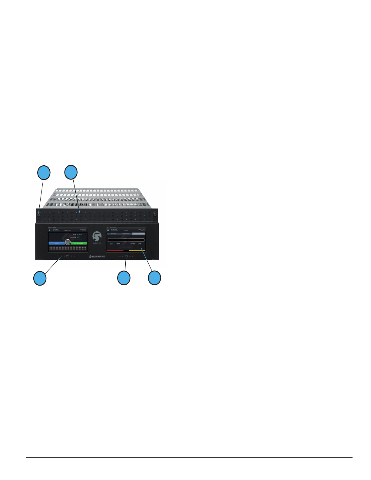
FIGURE 2-1: SG-System 5 front with door closed
1. Thumb screws to hold faceplate closed
2. Line card status indicators (top LED is watchdog, middle LED is status
and bottom LED is network)
3. SG-CPM5 Status LEDs (from left to right: Console, Trouble, Network,
Watchdog, Automation)
4. Quick HOME button
5. 7-inch resistive touch LCD screen
- 8 -
Page 9
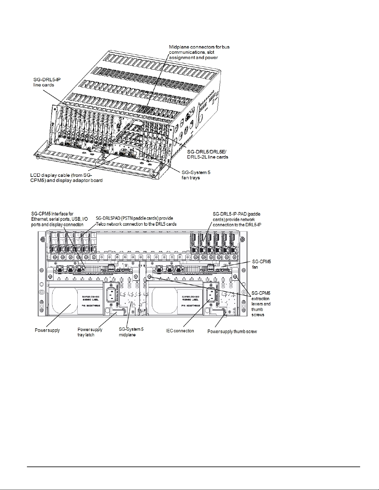
FIGURE 2-2: SG-System 5 front with door open
2.0 Introduction
FIGURE 2-3: SG-System 5 back
NOTE: Employ only 26 AWG wires for the Telco connections.
- 9 -
Page 10

2.0 Introduction
2.1.3 Description
The basic configuration consists of one 19-inch rack mounted chassis comprising the following:
l SG-MLRF5 - Metal rack of the SG-System 5 with SG-MP5
l SG-PSU5-600 - 600W power supply unit provides power to all system modules
l SG-PSU5-250 - 250W power supply unit provides power to all system modules
l SG-CPM5 - Central processing module controls all communication to and from receiver modules and printers
l SG-UIB5 - Touch screen user interface
l SG-DRL5-IP - Internet protocol line card
l SG-DRL5-IP PAD - Paddle card for SG-DRL5-IP provides network connection
l SG-MLRF5-RM - Rack mount rails
l SG-S5LFANTR - Line card fan tray
l SG-S5CFANTR - SG-CPM5 fan tray
l SG-S5SERCAB - Y cable for serial connection to the SG-CPM5 for automation/printer
l SG-SYS5MEM4 - Removable EMMC memory
l SG-SYS5DDR31 - DDR3 RAM 1GB
l SG-CPM5BATT - SG-CPM5 real time clock battery
l SG-DRL5 - Single line PSTN card
l SG-DRL5E - Single line PSTN card with backup channel and 2-way audio bridge
l SG-DRL5-2L - Dual line PSTN card
l SG-DRL5PAD - Paddle card for SG-DRL5/DRL5E/DRL5-2L PSTN cards
l SG-ADPT5 - Adapter card for SG-DRL5/DRL5E/DRL5-2L PSTN cards
2.1.4 Specifications
Dimensions
Depth: 27.5 in. (69.85 cm)
Width: 19 in. (48.26 cm)
Height: 7 in. (17.78 cm)
Required rack space: 4U
SG-System 5 UL Electrical:
Input voltage: 100-240 VAC, 50/60Hz.
Input current 600W: 8A max (RMS) @ 100VAC
Input current 250W: 3A max (RMS) @ 100VAC
Backup power supply: External UPS (not supplied)
In a two SG-CPM5 configuration, a redundant SG-PSU5 can be inserted in the second slot. In the event of a SG-PSU5 failure, the redundant SGPSU5 automatically assumes operation. These modules are hot swappable (can be removed and replaced while the system is in operation) if a working,
redundant SG-PSU5 is installed. Both PSU units used in the system must have the same power rating.
Environmental:
Temperature: 0-49°C (32 - 120°F)
Humidity: 93%RH, non-condensing
Accounts:
ULC Line Security Levels: A1-A4 (active channels) or P1-P3 (passive channels)
Printers (UL/ULC Listed Installations):
Serial: Seiko DPU-414
DACT Compatible communication formats (ULC Passive channels): SIA, CID
Encryption: AES 128 bit
2.2 System features
2.2.1 SG-System 5
l Reduced size of 4U in height for improved receiver room logistics management
l CMS access to visual verification files through SG-System 5 Console
l Upgradeable through the SG-System 5 Console
l Enhanced hardware diagnostics via SG-System 5 Console
l Static IP for programming of network protocols
l Real time system status via intuitive user touchscreen interface
l Supports visual verification features for DSC PowerSeries Neo
l Monitor up to 1,474,560 IP communicators (Cellular or Ethernet) with up to 24 IP line cards
- 10 -
Page 11
2.0 Introduction
l Line card capacity starting at 4,094 IP accounts, upgradable to 61,440 via licenses
l Standard line card capacity of 512 visual verification, 512 supervised IP accounts, and 3070 unsupervised
l Upgradeable memory to handle extensive future IP account capacity
l Network trouble detection is displayed on LCD/printer and automation software
l Data network polling environment for replacement of an existing DVACS network using a TL-300. Meets the 90-second ULC requirement for
this option
l A security function communicates to the central station when a module is removed and replaced
l The T-LINK accounts table and data encryption keys are stored in the local database
l Supports up to 24 PSTN line interfaces with the SG-DRL5E/DRL5 (24 max) or up to 48 PSTN line interfaces with the SG-DRL5-2L (24 max)
NOTE: The SG-DRL5-IP can only receive data from the following transmitters: TL150, TL250*, TL250DV, TL300*, TL300CF*, GS3055*,
GS3055-I, GS3055-ICF*, GS3060*, TL26X*, GS206X*, TL26XGS*, GS31XX, 3G2060(R)*,TL2603G(R)*, 3G3070*, 3G3070RF*,
3G3070CF*, TL2803G(R)(E)*, 3G2080(R)(E)*, TL280(R)(E)*, 3G4000*, 3G4000RF*, 3G4010, 3G4010CF
* UL/ULC Listed, x = 0, 5.
2.2.2 Visual Verification
Visual Verification enables the system operator to view images and hear audio captured during an alarm event. The images (JPG) and audio (WAV)
files are sent via Ethernet to the SG-DRL5-IP where they are converted to films (AVI) for viewing on the SG-System 5 Console.
Data such as detector ID, zone ID, film type, file size, number of files in film and event time is available for each Visual Verification event.
2.3 Approvals
2.3.1 Industry approvals
l UL 1610 Central Station Burglar Alarm Units
l UL 864 10th Edition Standard for Control Units and Accessories for Fire Alarm Systems
l CAN/ULC-S304-16 Signal Receiving Centre and Premises Burglar Alarm Control Units
l CAN/ULC-S559-13 Equipment for Fire Signal Receiving Centres and Systems
l EN60950-1:2006 Standard for Information Technology Equipment.
l AS/NZS 60950.1:2003 Information Technology Equipment - Safety
l CISPR22 Class B Information Technology Equipment - Radio Disturbance Characteristics - Limits and Methods of Measurements
l EN50130-4 Immunity requirements for components of fire, intruder and social alarm systems
l NIST validation certificate number 2913 for AES 128 bit encryption.
For UL listed installations, the equipment must be installed in accordance with the requirements of NFPA72, NFPA70, UL827 and the authority having
jurisdiction.
SG-System 5 with SG-DRL5-IP Line Card is ULC listed for active communication channel security level A1 - A4 when used in conjunction with TLink TL250, T-Link TL300, TL260, TL260GS, GS2060, 3G2060(R), TL2603G(R), 3G3070(RF)(CF), TL2803G(R)(E), 3G2080(R)(E), TL280(R),
TL2803G(E)(R), 3G2080(E)(R), TL280(E)(R), 3G4000, and 3G4010 Internet/Intranet and/or GSM-GPRS alarm communicators. For this type of
application the supervision and encryption features have to be enabled. The receiver can be used also in conjunction with ULC listed passive communication systems based on the configuration of the systems at the protected premises.
- 11 -
Page 12
2.0 Introduction
For ULC Installations the equipment must be installed in accordance with the requirements of ULC-S561 and ULC-S301 Standards and the authority
having jurisdiction. SG-System 5 with SG-DRL5/DRL5E/DRL5-2L PSTN line cards is ULC listed for passive communication channel security levels
P1-P3 when used in conjunction with compatible alarm systems using Industry Open SIA standard communication formats Contact ID or SIA.
This product has been approved by the California State Fire Marshal (CSFM) pursuant to section 13144.1 of the California Health and Safety Code.
See CSFM Listing No. 7300-1273:0157 for allowable values and/or conditions for use concerning material presented in this document. The approval is
subject to reexamination, revision and possible cancellation.
2.3.2 UL864 programming requirements
NOTE: Users, Installers, Authorities having Jurisdiction and other involved parties; this product incorporates field programmable soft-
ware. In order for the product to comply with the requirements in the Standard for Control Units and Accessories for Fire Alarms
Systems, UL 864, certain programming features or options must be limited to specific values or not used at all as indicated below.
SG-CPM5 - UL864 programming requirements
Opt # Program option Permitted in UL864? (Y/N) Possible settings Settings permitted (UL 864)
202 Buzzer N Enabled/Disabled Enabled
411 Heartbeat Timer Y 00-FF Not Allowed 00
601 CPM5 1 Fan Trouble N Enabled/Disabled Enabled
602 CPM5 2 Fan Trouble N Enabled/Disabled Enabled
603 PSU 1 Trouble N Enabled/Disabled Enabled
604 PSU 2 Trouble N Enabled/Disabled Enabled
609 UPS AC 1 Trouble N Enabled/Disabled Enabled
610 UPS AC 2 Trouble N Enabled/Disabled Enabled
611 UPS Battery 1 Trouble N Enabled/Disabled Enabled
612 UPS Battery 2 Trouble N Enabled/Disabled Enabled
615 SG-Serial Automation Sec 1 Trouble N Enabled/Disabled Enabled
617 Serial CPM 1 Printer 1 Trouble N Enabled/Disabled Enabled
618 Serial CPM 2 Printer 1 Trouble N Enabled/Disabled Enabled
619 Serial CPM 1 Printer 2 Trouble N Enabled/Disabled Enabled
620 Serial CPM 2 Printer 2 Trouble N Enabled/Disabled Enabled
621 SG-TCP Automation Pri - Trouble N Enabled/Disabled Enabled
631 SG-TCP Automation Sec - 1 Trouble N Enabled/Disabled Enabled
665 TCP Printer Pri - 1 Trouble N Enabled/Disabled Enabled
675 TCP Printer Sec - 1 Trouble N Enabled/Disabled Enabled
SG-DRL5-IP
Opt # Program option Permitted in UL 864 (Y/N)
221 Transmitter Absent Debounce Time N 5-65535 200
222 Transmitter Restoral Debounce Time N 5-65535 200
301 Transmitter Unencrypted Trouble N Enabled/Disabled Enabled
302 Unknown Account Trouble N Enabled/Disabled Enabled
303 Supervised Accounts Exceeded Trouble N Enabled/Disabled Enabled
SG-DRL5-2L/DRL5E/DRL5
Opt # Program option
104/204 2-Way Activation Time N 00-FF 00
12F/22F
17B/27B 3-Digit Account Codes to Activate 2-Way Audio N 00-FF 00
17C/27C Alarm Codes to Activate 2-Way Audio N 00-FF 00
17D/27D Supervised Accounts Exceeded Trouble N 00-FF 00
4- and 5-digit Account Codes to Activate 2-Way
Audio
Permitted in UL 864?
Possible
settings
(Y/N)
N 00-FF 00
Settings permitted (UL 864)
Possible set-
tings
Settings permitted (UL
864)
- 12 -
Page 13
2.0 Introduction
2.3.3 Printers
Serial printer
For UL and ULC Listed applications, the following UL/ULC Listed printer can be used with the SG-System 5:
l Seiko DPU-414
TCP/IP printer
For UL Listed applications, the UL Listed SG-System 5 Console software can be used with the SG-System 5.
NOTE: For ULC Listed applications, the Console Printer application is considered supplemental and is only allowed to be used in con-
junction with a compatible ULC Listed printer.
SG-System 5 Console software system requirements
Compatible operating systems:
l Microsoft Windows 2008 Server (32 and 64 bit)
l Microsoft Windows 7 (32 and 64 bit)
l Microsoft Windows 8 (32 and 64 bit)
l Microsoft Windows 8.1 (32 and 64 bit)
l Microsoft Windows 10 (32 and 64 bit)
NOTE: Requires.NET Framework 3.51.
Hardware requirements:
l Intel Atom CPM @ 1.6GHz and 1 GB of RAM
NOTE: Do NOT use printer cables that have only one common ground wire.
2.3.4 UL Manual mode
For UL Manual mode, each event activates the internal buzzer to be acknowledged manually. Each event is sent automatically to the connected printer.
NOTE: A user must be logged in before acknowledging signals. A logged in user remains logged in until a new user enters a valid user
name and password or if the SG-CPM5 resets or reboots.
2.3.5 SG-System 5 power limited circuit separation
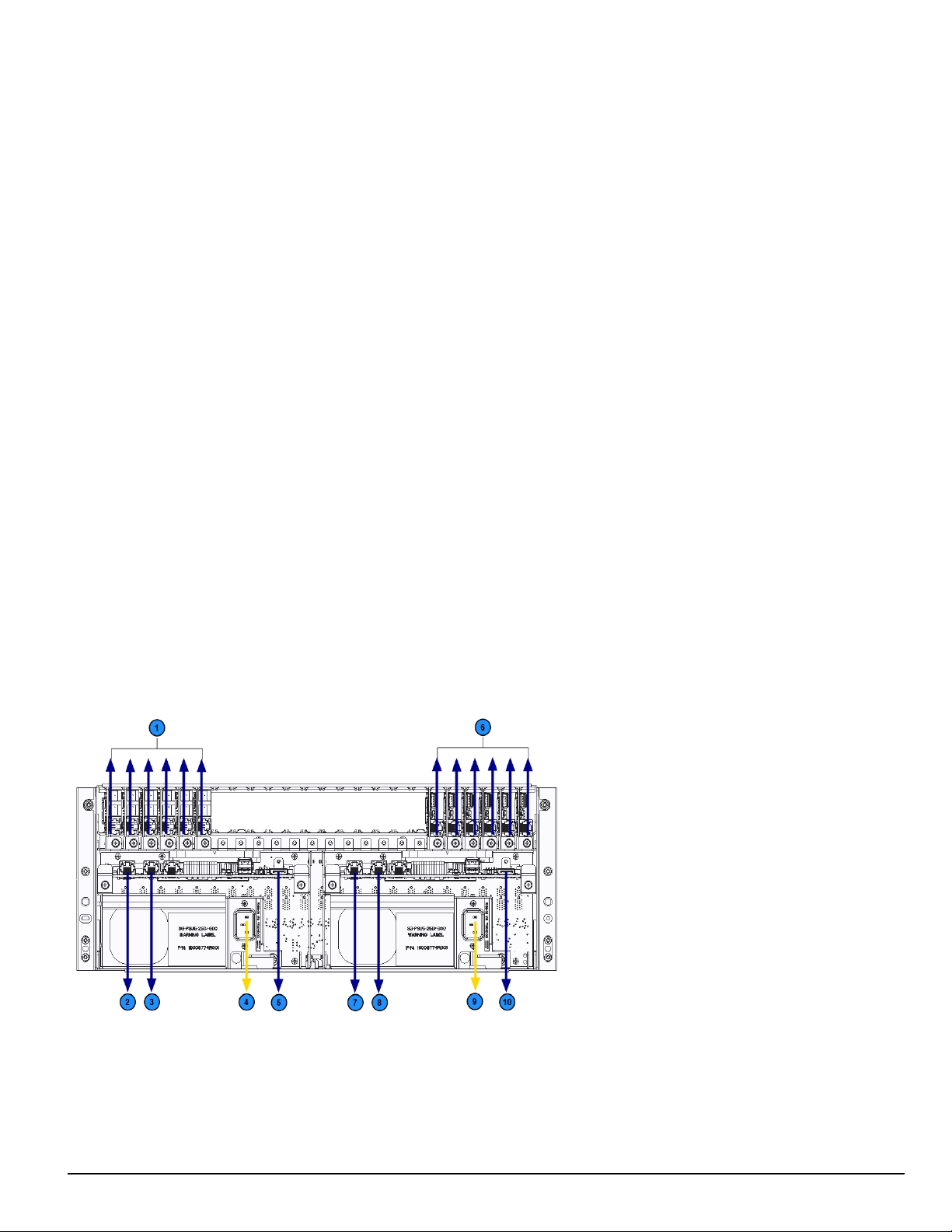
FIGURE 2-4: SG-System 5 power limited circuit separation from non-power limited circuit diagram
1. Secondary line card phone connections 6. Primary line card Ethernet connections
2. Secondary SG-CPM5 Ethernet connection 7. Primary SG-CPM5 Ethernet connection
3. Secondary SG-CPM5 automation and printer port 8. Primary SG-CPM5 automation and printer port
4. Secondary SG-PSU5 AC power connection (see note) 9. Primary SG-PSU5 AC power connection (see note)
5. Secondary SG-CPM5 display connection 10. Primary SG-CPM5 display connection
NOTE: Employ only 26 AWG wires for the Telco connections.
- 13 -
Page 14

2.0 Introduction
NOTE: The power cord must be routed ¼ inch away from all other cables coming from or which are part of the SG-System 5.
- 14 -
Page 15

3.0 Receiver Setup and Operation
In this chapter...
3.1 SG-System 5 quick install guide 16
3.1.1 Receiver installation 18
3.1.2 SG-CPM5 LEDs 20
Page 16
3.0 Receiver Setup and Operation
3.1 SG-System 5 quick install guide
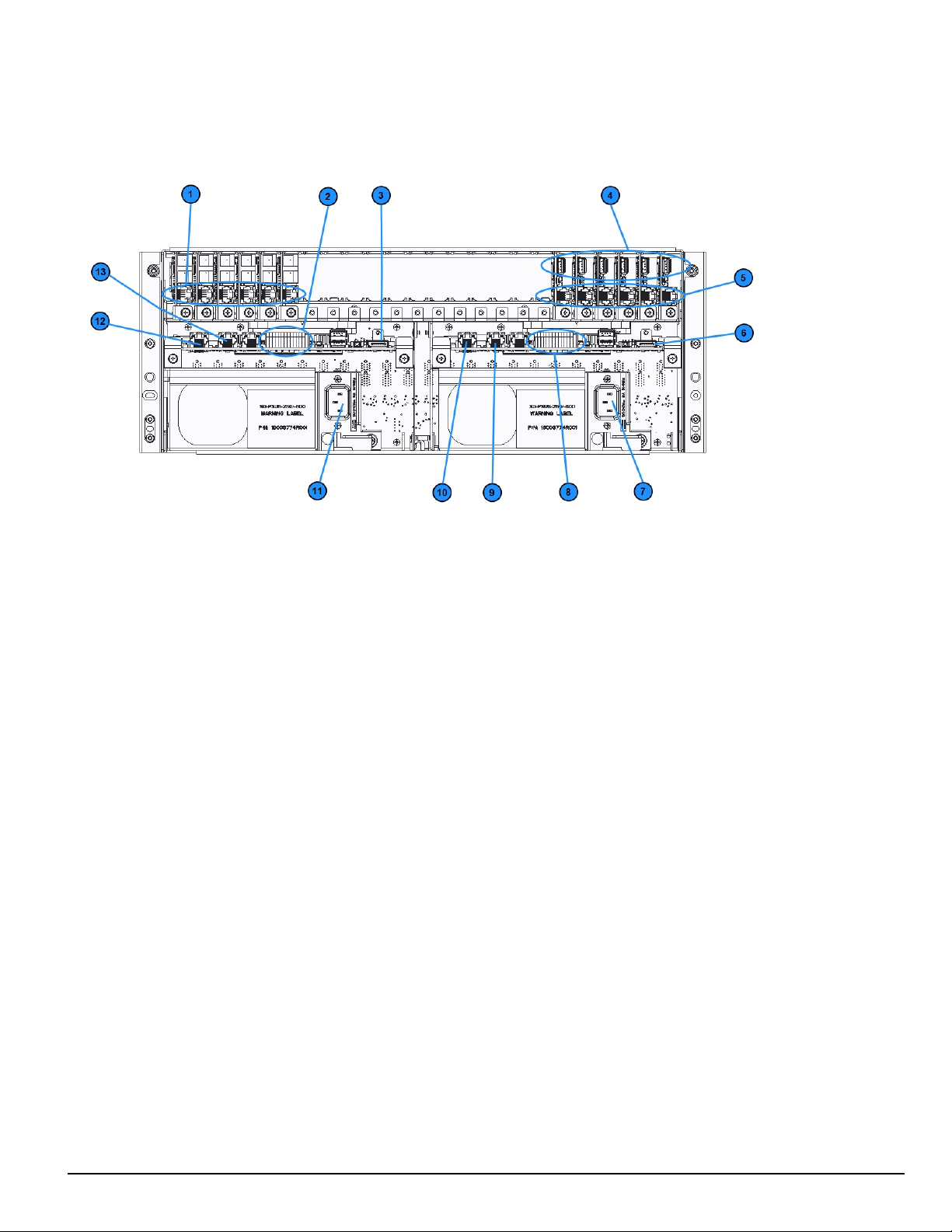
FIGURE 3-1: SG-System 5 connections (back)
1. Line card phone line connections
2. Secondary SG-CPM5 I/O terminal connections
3. Secondary SG-CPM5 display connection
4. Line card USB connections
5. Line card Ethernet connections
6. Primary SG-CPM5 display connection
7. Primary SG-PSU5 AC power connection
8. Primary SG-CPM5 I/O terminal connections
9. Primary SG-CPM5 automation and printer port
10. Primary SG-CPM5 Ethernet connection
11. Secondary SG-PSU5 AC power connection
12. Secondary SG-CPM5 Ethernet connection
13. Secondary SG-CPM5 automation and printer port
NOTE: This equipment must be operated by SERVICE PERSONS only within RESTRICTED ACCESS LOCATIONS; refer to this
Operating Manual for Safety Instructions.
NOTE: For equipment used at signal receiving centers and intended to facilitate IP communication (hubs, routers, NID, DSL/cable
modems), 24-hour backup power is required.
NOTE: To test the operation of LEDindicators and LCD:
From the LCD, click the menu at the top right>> login/options>>More Options>> Visual indicator test>>yes.
NOTE: When using private, corporate, and high-speed data networks, network access and domain access policies are set to restrict unau-
thorized network access and ‘spoofing’ or ‘denial of service’ attacks. Select an ISP that provides redundant servers/systems,
backup power, routers with firewalls enabled and methods to identify and protect against these types of attacks (‘e.g., ‘spoofing’,
'DoS').
NOTE: Install external devices connected to SG-CPM5 Ethernet, SG-CPM5 automation printer ports and SG-CPM5 I/O terminal con-
nections in the same room as the SG-System 5. Maintain 6.5 mm (1/4 inch) of separation between power limited and non-power limited circuits. Use power limited, supervised circuits only.
- 16 -
Page 17
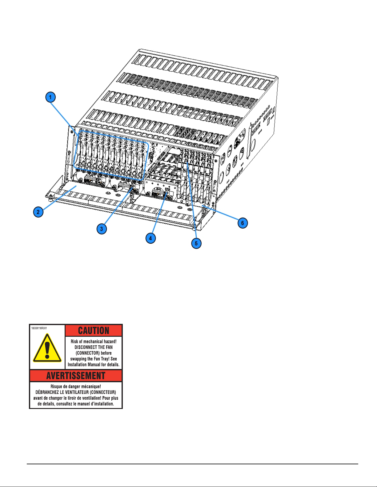
FIGURE 3-2: SG-System 5 front with door open
3.0 Receiver Setup and Operation
1. Line cards
2. Warning label
3. Primary display power connection
4. Secondary display power connection
5. PSTN line card
6. Line card extraction plate
FIGURE 3-3: SG-System 5 warning label
WARNING: To reduce the risk of electric shock, the product is provided with a grounding type power supply IEC receptacle. Connect product using
an appropriate IEC cable to a grounded receptacle.
Do not connect to a receptacle controlled by a switch.
l RS-232 Serial Automation Output: Provides serial connection to a local computer running automation software. A null modem serial cable must
be used.
l RS-232 Serial Printer Output: Provides serial connection to a local computer or serial printer. A null modem serial cable must be used.
- 17 -
Page 18
3.0 Receiver Setup and Operation
l Ethernet Output 1 GigE: Traditional automation communication is provided via port 1025 on the Ethernet connection. This primary port is a
Sur-Gard standard output and provides Sur-Gard standard automation protocol output.
CAUTION: The Ethernet communication lines must be connected first to an approved (acceptable to the local authorities) type NID (Network Interface
Device) before leaving the premises (e.g., UL installations, UL60950 Listed NID).
NOTE: All external devices should be mounted in the same room as the receiver.
All circuits are power limited except AC input.
Maintain 6.5 mm (1/4 inch) separation between power limited and non-power limited circuits.
All outputs are supervised.
3.1.1 Receiver installation
Sur-Gard recommends testing the receiver before actual installation. Becoming familiar with the connections and setup of the unit on the workbench simplifies the final installation.
The following items are required:
l 1 IEC power supply cord per SG-PSU5
l Philips #1 screwdriver
l Phillips #2 screwdriver
l 5/16 inch [or 8 mm] nut driver
l Depending on rack mounting:
l 8 clip nuts for the 19-inch rack
l 8 screws to fit into the clip nuts
1. Unpack the components for the SG-System 5.
NOTE: Carefully unpack the receiver and inspect for shipping damage. Notify the carrier immediately of any apparent damage.
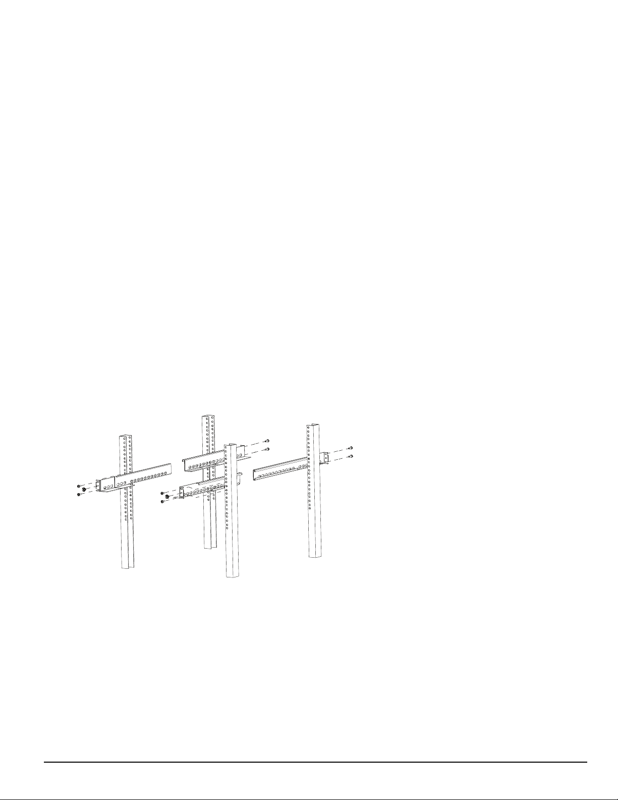
2. Mount the rails to the 19-inch rack:
a. Slide the rails together.
b. Insert the clip nuts into the 19-inch rack 1U apart on the front and the back of the rack, leaving minimum 4U of space from the bottom
of the rail.
c. Place the rails and then secure in place with rack screws (four per rail, two on the front and two on the back).
d. Unfasten the front rail screws and set aside.
FIGURE 3-4: Rail installation
NOTE: Maximum distance between front and rear rails is 31 inches (78.74 cm)
CAUTION: This component is heavy and requires two people to lift. Keep fingers clear of rails.
3. Slide the SG-MLRF5 subrack onto the rails.
4. Unfasten the thumb screws and open the front plate.
5. Fasten the thumb screw set aside from the rails.
- 18 -
Page 19

3.0 Receiver Setup and Operation
Rail Screw
Rail Screw
FIGURE 3-5: Securing SG-MLRF5 to rack
6. Install optional secondary LCD:
a. Unscrew the four nuts holding the cover plate.
b. Push the blank plate from the front to remove it.
c. Remove the display cable from its holder in the cover plate.
d. Discard the cover plate.
e. Remove the plastic sheet covering the LCD.
f. Place the LCD onto the front plate.
g. Connect the power cable from the SG-MLRF5 to the LCD (tab up).
h. Attach the display cable.
i. Install the cable holder using the two screws provided. Ensure both the display cable and the LCD power cable are secured.
j. Place the metal shield on top of the LCD.
k. Fasten the ground strap.
l. Screw on all four nuts (do not over-tighten).
7. Insert the fan tray and connect the fan tray wire. Make sure the fan tray is between the two guides. Fasten the thumb screws. Repeat the process
for additional fan trays.
8. Insert all cards, starting with slot 1, into their appropriate positions in the rack. Ensure there are no open slots between cards. Fasten the thumb
screws.
9. Close the front plate and fasten the thumb screws.
10. At the back of the SG-System 5:
a. Insert the SG-CPM5 partially and connect fan (at the back). The SG-CPM5's fan connector tab should be up.
b. Insert the SG-CPM5 completely in the rack. Fasten the thumb screws.
c. Connect the LCD display port cable and a network cable to the SG-CPM5.
d. Insert a paddle card into each slot with a SG-DRL5-IP line card. Fasten the thumb screws.
e. Connect a network cable to each paddle card.
f. Insert the SG-PSU5(s) into the rack and fasten the thumb screw.
g. Connect the main power using a standard computer IEC cable (not supplied).
11. The LCD powers up and displays internal troubles (e.g., printer, automation).
12. Press the ACK button and log in (Default: Admin//adminpass).
13. Press the ACK button until all of the initial signals have been acknowledged (ACK button has stopped flashing and the buzzer has been
silenced).
NOTE: Internal diagnostics may require more than one minute during the power up sequence.
- 19 -
Page 20
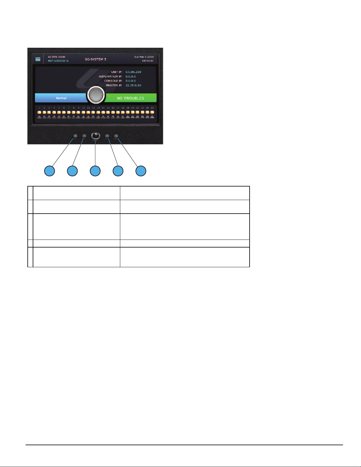
3.1.2 SG-CPM5 LEDs
3 4
5
1
2
3.0 Receiver Setup and Operation
1. Console Connected (Green)
2. Trouble Status (Yellow)
Network Status
3.
(around the home button)
4. Watchdog (Blue) Flashing = Normal , Off/On – SG-CPM5 failure
5. Automation (Green)
ON = Console connected
OFF = Console disconnected
ON = Troubles present
OFF = No troubles present
Blue = 1Gb/s
Green = 100Mb/s
Orange = 10Mb/s
Red = network absent
ON = Automation connected and system is active
Flashing = Automation is connected and system is in standby
OFF = Automation disconnected
- 20 -
Page 21

4.0 Hardware Descriptions and Specifications
In this chapter...
4.1 SG-MLRF5 22
4.1.1 SG-MP5 midplane 22
4.1.2 SG-S5CFANTR – SG-CPM5 fan tray 22
4.1.3 SG-MLRF5-RM – Mounting rails 23
4.2 SG-CPM5 - Central processing module 23
4.2.1 SG-CPM5 I/O terminal pin-outs 24
4.2.2 SG-CPM5 Setup 25
4.2.3 SG-CPM5BATT - RTC battery 26
4.2.4 SG-S5SERCAB - Y-cable 27
4.2.5 SG-CPM5 fan tray replacement 28
4.2.6 UPS setup 29
4.3 SG-DRL5-IP - IP line card 30
4.3.1 SG-DRL5-IP configurations 31
4.3.2 SG-DRL5-IP LED status indicators 31
4.3.3 SG-DRL-IP setup 33
4.4 SG-DRL5-IP PAD – SG-DRL5-IP paddle card 36
4.5 SG-S5LFANTR - Line card fan tray 36
4.6 SG-DRL5/DRL5E/DRL5-2L - Line card 37
4.7 SG-DRL5-PAD - Paddle card 37
4.8 SG-DRL5-ADPT - Adapter card 38
4.9 SG-DRL4-2L upgrade to System 5 39
4.10 Installing SG-DRL5 PSTN cards in a SG-System 5 40
4.11 SG-PSU5 250W and 600W power supply 41
4.11.1 SG-PSU5-600/SG-PSU5-250 installation 42
4.11.2 Power management 42
4.12 SG-UIB5 - User interface 42
4.12.1 SG-UIB5 LCD replacement 43
4.13 SG-SYS5MEM4 - Expandable EMMC 44
4.14 DDR3 RAM 45
4.15 SD card 45
Page 22
4.0 Hardware Descriptions and Specifications
4.1 SG-MLRF5
The SG-MLRF5 houses the components of the SG-System 5 and is secured into a 19-inch rack by the SG-MLRF5-RM rails. The SG-MLRF5 ships
with the mid-plane, two CPM fans and one LCD pre-installed.
FIGURE 4-1: SG-MLRF5 rack
4.1.1 SG-MP5 midplane
The SG-MP5 interconnects system modules.
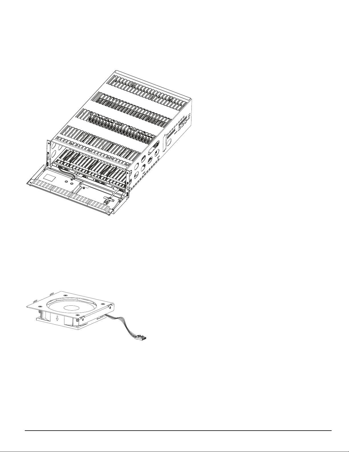
4.1.2 SG-S5CFANTR – SG-CPM5 fan tray
The SG-S5CFANTR cools the SG-CPM5 while the SG-CPM5 is running. The SG-S5CFANTR is mounted above the SG-CPM5 in the MLRF5. It
must be plugged into the SG-CPM5 to function.
FIGURE 4-2: SG-S5CFANTR
- 22 -
Page 23
4.0 Hardware Descriptions and Specifications
1 2 6 83 4 5 7
9
11
10
12
4.1.3 SG-MLRF5-RM – Mounting rails
The SG-MLRF5-RM are used to hold the MLRF5 in place in the 19-inch rack. The mounting rails are installed in the rack before the SG-MLRF5 to
allow it to slide in place. The rails must be mounted on the front and back of the 19-inch rack. This product does not support racks that only have front
supports. Eight clip nuts or screws (not included) are required to install each rail.
FIGURE 4-3: SG-MLRF5-RM
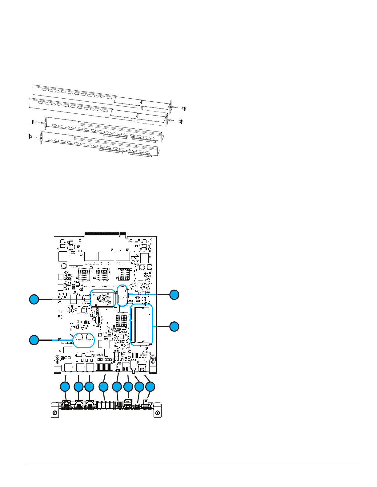
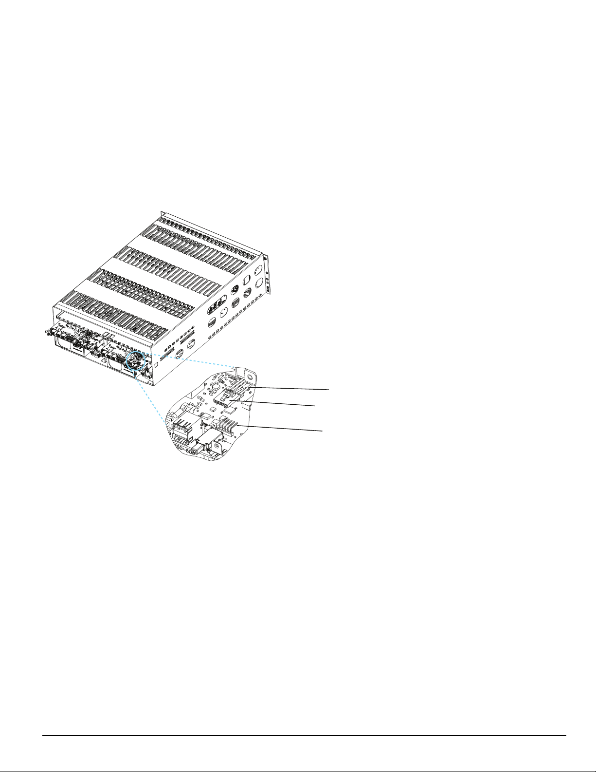
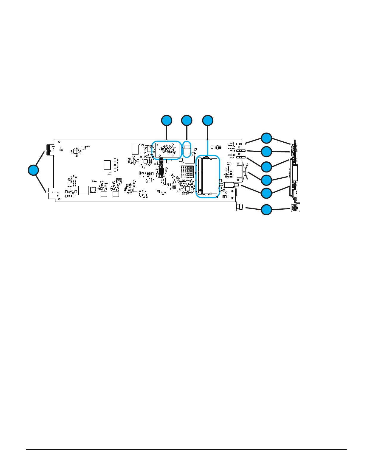
4.2 SG-CPM5 - Central processing module
The SG-CPM5 central processing module collects system information and directs line card information to the appropriate outputs. Along with its connection to the LCD touch screen, the SG-CPM5 features a TCP/IP connection (supports 10/100/1000Mbps), serial connections for automation and
printer, and I/O terminal pin outs for external ACKing and monitoring of the UPS and Buzzer/Trouble/Network follower. The printer is supervised for
loss of power, off-line, paper out and other trouble conditions. The communication link to the automation computer through the RS-232 and TCP/IP
port can be monitored by the supervisory heartbeat transmissions.
FIGURE 4-4: SG-CPM5
1.2.Ethernet - supports 10/100/1000Mbps
Serial automation 1 and serial printer 1
3.4.For future use
I/O terminals
5.6.USB OTG (for future use)
USB (for future use)
7.8.Decommission switch (for future use)
Display port connection
9.
DDR3 memory
10.
SD card (for future use)
11.
Real time clock (RTC) back-up batteries
12.
Expandable module (for AHS functionality)
- 23 -
Page 24
4.0 Hardware Descriptions and Specifications
1 3 2 4 5 7 6 8 9 10 1211 13
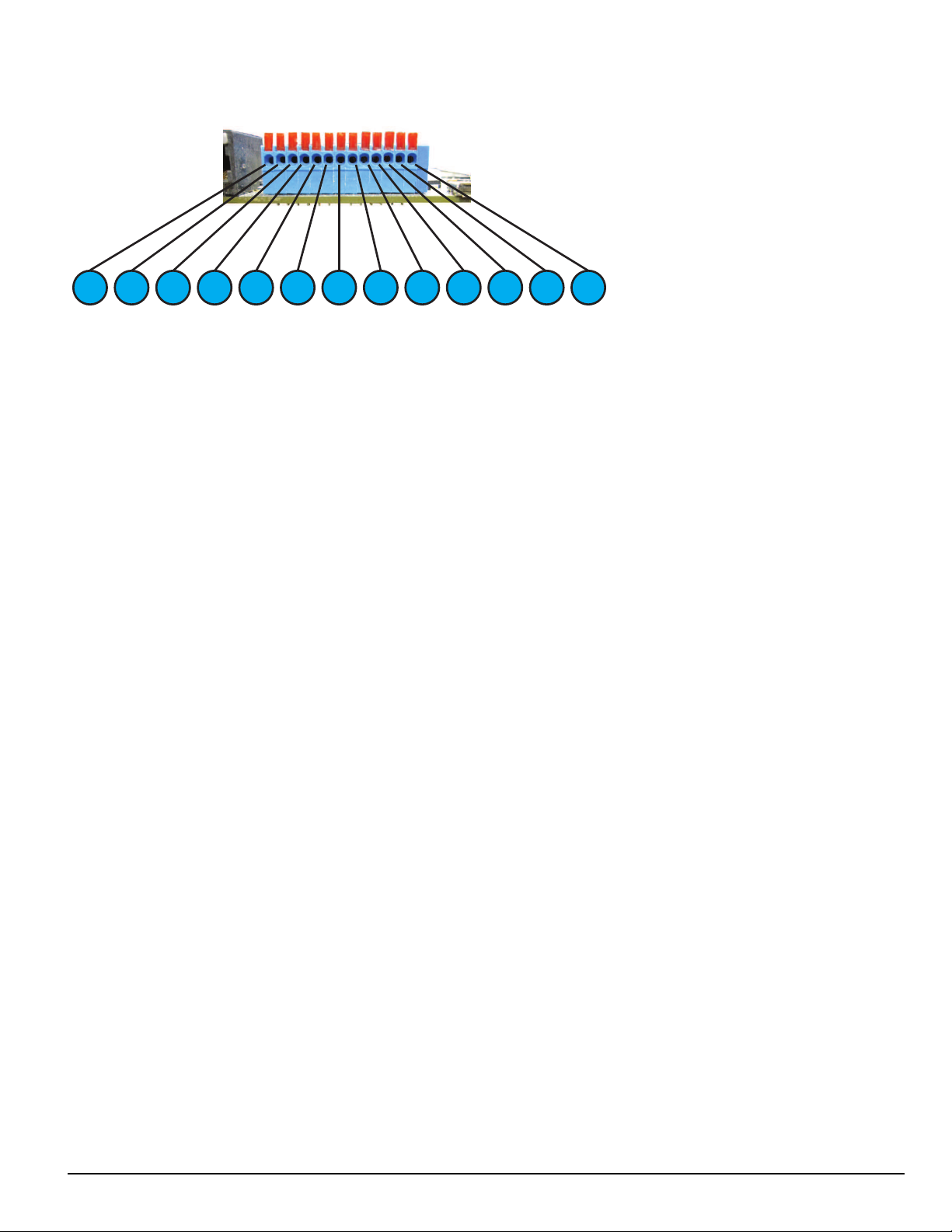
4.2.1 SG-CPM5 I/O terminal pin-outs
1. Input1 UPS AC Failure: UPS AC normally closed output opens on failure.
2. GND Common (ground)
3. Input2 UPS DC Failure: UPS battery normally closed output opens on failure.
4. Input3 Remote ACK: When the SG-CPM5 is in manual mode, pressing the ack button (front panel) or connecting this input to
ground (typically using a button) acknowledges the first event on the LCD.
5. GND Common (ground)
6. Input Future use
7. OutputR1 Follow Buzzer: Relay contact closes following the buzzer caused by manual mode.
8. R1 Relay 1 Common
9. OutputR2 Trouble Output: Relay contact closes when the trouble (Status) LED activates.
10. R2 Relay 2 Common
11. OutputR3 Network Status: Relay contact closes when the network is present.
12. R3 Relay 3 Common
13. GND Common (Gound)
For ULC installations, the equipment shall be rack-mounted and powered by a permanently wired supply in accordance with C22.1, Canadian Electrical
Code, Part 1, Safety Standard for Electrical Installations, section 32. This equipment is intended to utilize the building emergency AC supply system for
their standby supply (e.g., UPS, batteries in conjunction with engine-driven generators).
4.2.1.1 UPS AC Failure – Pin 1
UPS AC Failure – this normally closed input is used with backup power supplies that support output activation for status indication. When this input is
activated, the SG-CPM5 indicates a trouble condition for UPS AC Fail (see SG-CPM5 option [609] for the primary and [610] for the secondary).
4.2.1.2 UPS DC Failure – Pin 3
UPS BATT Failure – this normally closed input is used with backup power supplies that support output activation for status indication. When this input
is activated the SG-CPM5 indicates a trouble condition for UPS Battery Fail (see SG-CPM5 option [611] for the primary and [612] for the secondary).
4.2.1.3 Remote ACK – Pin 4
Remote Ack – this input is used to provide a method to acknowledge an alarm condition (while the receiver is in manual mode) from a remote location.
The Remote Ack input is available any time that the front panel Ack button is available.
4.2.1.4 Buzzer Follow Output – Pin 7
Manual Mode Buzzer Follow – this output is activated in synchronization with the buzzer output of the SG-CPM5. When the buzzer is silenced/ended,
the output deactivates. This output is used to monitor the buzzer when the receiver is in a remote location.
4.2.1.5 Trouble Status Output – Pin 9
Trouble output – this output is activated with the trouble status output of the SG-System 5. Any enabled trouble condition on the system activates the
output. The output deactivates once all trouble conditions have been cleared. This output is used to monitor trouble conditions when the receiver is in a
remote location.
- 24 -
Page 25
4.0 Hardware Descriptions and Specifications
Fan Cable
Fan Connector
Pin 1
4.2.1.6 Network Status Output – Pin 11
Network Status output – This output is activated when there is a network absent condition. Once the network connection is restored, this output deactivates. This output is used to monitor the network status when the receiver is in a remote location.
4.2.2 SG-CPM5 Setup
4.2.2.1 Connecting the SG-CPM5 Fan Cable
To connect the CPM's fan cable, partially slide the SG-CPM5 into the SG-MLRF5 and connect the cable to the SG-CPM5 board with the connector
facing up. Slide the SG-CPM5 all the way into the rack.
FIGURE 4-5: SG-CPM5 Fan Cable
4.2.2.2 Y-Cable
The Y-cable is used to connect the SG-CPM5’s RJ-45 port to serial cables. To connect it, plug it into the second RJ-45 port from the left.
4.2.2.3 RTC Battery
The SG-CPM5 has two replaceable A76 alkaline RTC batteries. Replace batteries approximately every five years.
To replace the RTC batteries, follow these steps:
1. Unfasten the SG-CPM5 thumb screws.
2. Partially remove the SG-CPM5 , disconnect the SG-CPM5 fan tray cable, then remove the SG-CPM5 fully.
3. Insert a small screwdriver into either side of the battery holder and push the battery out.
4. Insert the new battery into the holder (label up).
5. Repeat steps 3-4 for the other battery.
4.2.2.4 EMMC Memory
The SG-CPM5 has an optional add-on EMMC memory module that is required to expand the AHS table.
To replace the EMMC memory, follow these steps:
NOTE: If the EMMC is not already installed, please skip steps 3-4.
1. Unfasten the SG-CPM5 thumb screws.
2. Partially remove the SG-CPM5, disconnect the SG-CPM5 fan tray cable, then remove the SG-CPM5 fully.
3. Unfasten the two screws on the EMMC module.
4. Carefully lift the EMMC module off of the board.
- 25 -
Page 26

4.0 Hardware Descriptions and Specifications
*SNAP*
*SNAP*
PRESS
INSERT
ALIGN
NOTCH
5. Place the new EMMC module on the board.
6. Fasten the two EMMC screws.
7. Install the SG-CPM5 back into the SG-MLRF5.
4.2.2.5 DDR3 Memory
The SG-CPM5 incorporates replaceable/upgradable DDR3 required for normal operation.
To replace the DDR3 Memory, follow these steps:
1. Unfasten the SG-CPM5 thumb screws.
2. Partially remove the SG-CPM5, disconnect the SG-CPM5 fan tray cable, then remove the SG-CPM5 fully.
3. Push the clips on either side of the DDR3 away from the board. It should lift up automatically.
4. Slide the DDR3 out at a 45 degree angle.
5. Slide the new DDR3 in at a 45 degree angle (label up).
6. Push down until the clips engage.
7. Install the SG-CPM5 back into the MLRF5.
FIGURE 4-6: DDR3 Installation
4.2.3 SG-CPM5BATT - RTC battery
The SG-CPM5 requires two SG-CPM5BATT batteries on the board to power the Real-Time Clock (RTC) circuit. These batteries allow the SG-CPM5
to track the time even when the SG-CPM5 is completely powered down.
- 26 -
Page 27
4.0 Hardware Descriptions and Specifications
1
2
1
2
3
4
5
6
7
8
9
1
2
3
4
5
6
7
8
9
1
2
3
4
5
6
7
8
RJ-45 MALE
DB-9
MALE (2)
DB-9
MALE (1)
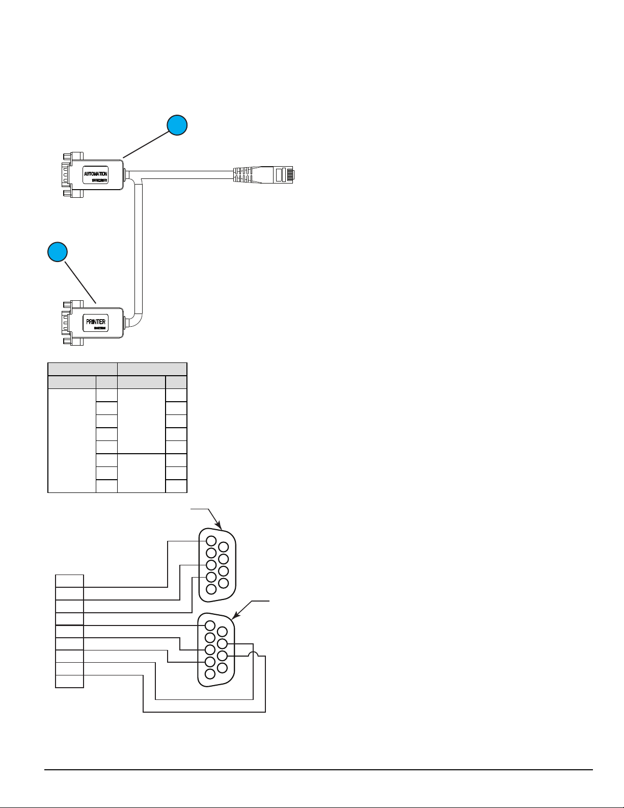
4.2.4 SG-S5SERCAB - Y-cable
The Y connector is used to branch out the RJ-45 printer/automation port on the SG-CPM5 to two serial connections:
1. Serial port 1 is for the automation.
2. Serial port 2 is for the printer.
Serial Pin OUTS:
From To
Connector Pin# Connector Pin#
RJ-45 Male
1
2 8
Printer
3 2
DB-9
4 3
5 5
6
Automation
7 3
DB-9
8 5
7
2
- 27 -
Page 28
4.0 Hardware Descriptions and Specifications
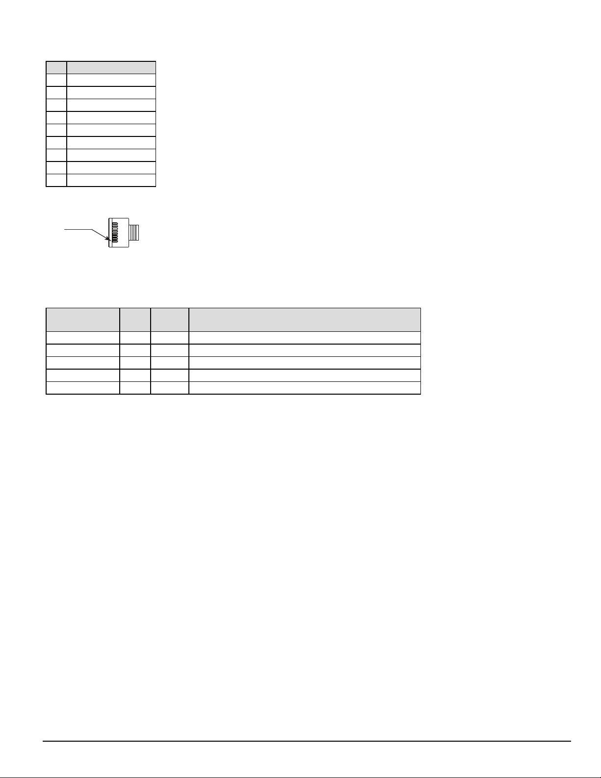
PIN 1
DB-9 pin OUTS:
Pin# Pin function
1 Data carrier detect
2 Receive data
3 Transmit data
4 Data terminal ready
5 Signal ground
6 Data set ready
7 Request to send
8 Clear to send
9 Ring indicator
FIGURE 4-7: RJ-45 Pin 1 location
4.2.4.1 Maximum connected cable length
The maximum cable length from the SG-SYSTEM 5 to another device (e.g., hub, UPS) is 3ft (0.9144 meters). All connections made in the same room
(termination must be within the secure premises).
Connector
I/0 Terminal 3 0.9144 Sounding/lighting/input devices
Serial printer 3 0.9144 Printer or PC- based printer (serial port)
Serial automation 3 0.9144 PC-based software (serial port)
LAN 3 0.9144 Network switch or direct to PC (crossover cable)
IEC connector 3 0.9144 UPS backup power supply or standard wall outlet (110/220VAC)
Length
(feet)
Length
(meters)
Typical termination
4.2.5 SG-CPM5 fan tray replacement
To replace an SG-CPM5 fan tray, first remove the SG-PSU5, the SG-CPM5 and paddle cards.
The steps are as follows:
1. Unplug the IEC cable from the power supply. Lift the red tab and unfasten the thumb screw.
2. Remove the SG-PSU5.
3. Unfasten the SG-CPM5’s thumb screws. Disconnect all the wires (Ethernet, automation/printer, I/O wires, and LCD cable).
4. Partially remove the SG-CPM5, disconnect the fan cable, and then remove the SG-CPM5 fully.
5. Unfasten the paddle card thumb screws and remove the paddle cards.
6. Unfasten the fan screws.
7. Grasp the fan, push away then pull down to remove.
8. Insert the new fan by pushing up and then back.
9. Fasten the two screws, ensuring that the fan is secure.
10. Replace the paddle cards removed in previous steps.
- 28 -
Page 29
4.0 Hardware Descriptions and Specifications
UPS LOW BAT Normally Closed
Common
UPS AC TROUBLE Normally Closed
UPS
AC In
AC Out
Input 2
Input 1
COM
IEC Power
Connector
EGND
1 3 2
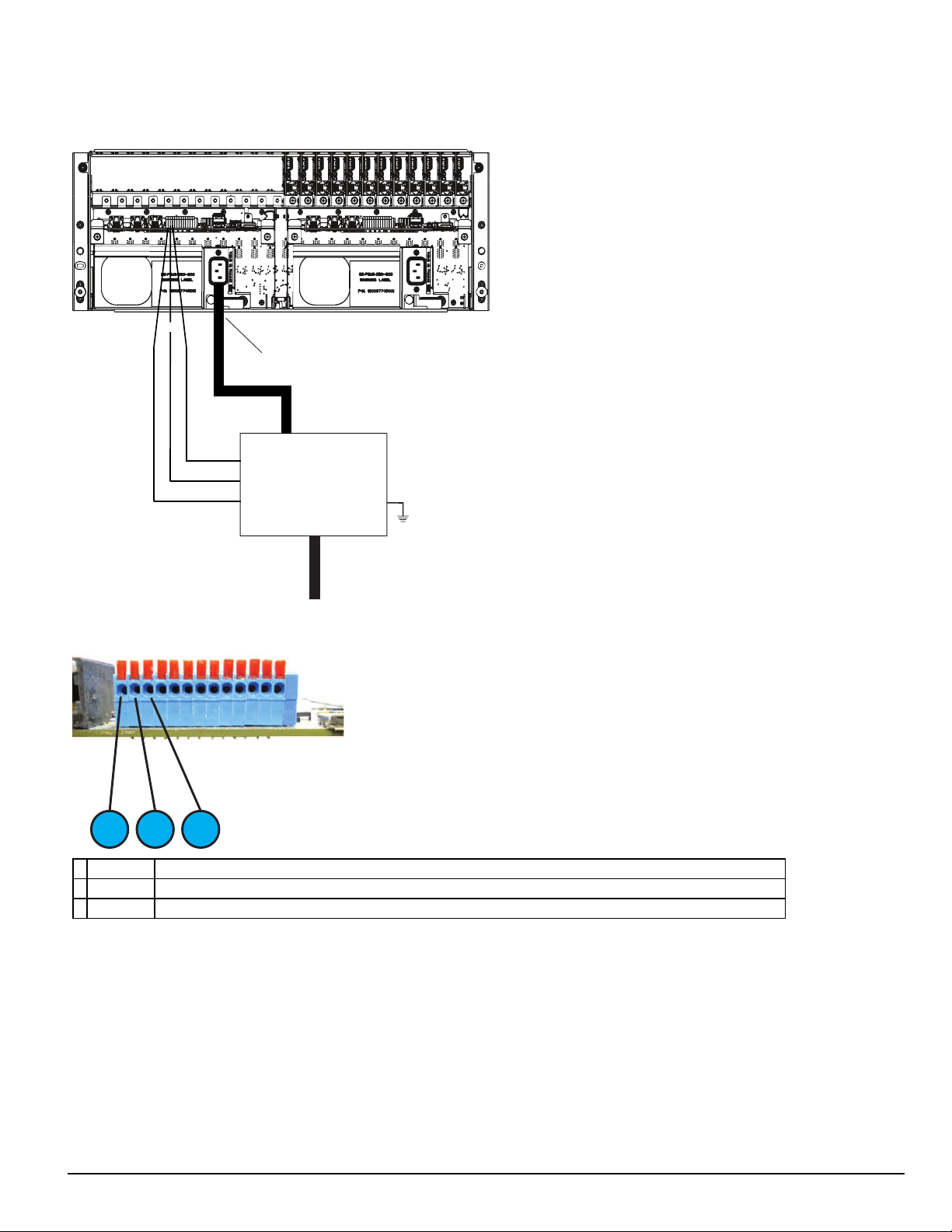
4.2.6 UPS setup
FIGURE 4-8: SG-System 5 UPSsupervision connection diagram
FIGURE 4-9: I/O Terminal UPS connections
1. Input 1 UPS AC Failure: toggles from ground to open on failure.
2. GND Common (ground)
3. Input 2 UPS DC Failure: battery of the UPS failed (toggles from ground to open on failure)
For UL/ULC installations, use a UL listed UPS (Uninterruptible Power Supply) for protective-signaling systems and/or a listed burglary alarm power
supply, as applicable.
NOTE: UPS connection is to be made using dry contact connections provided by the UPS.
For UL and ULC installation of model SG-System 5: UPS Output 120V AC/60Hz, 5A
For ULC Installations, the equipment shall be rack mounted and energized by a permanently wired supply in accordance with C22.1, Canadian Electrical
Code, Part 1, Safety Standard for Electrical Installations, section 32.
Connection to a UPS (Uninterruptible Power Supply) with minimum 24 hour standby capability is required.
WARNING: To reduce the risk of electrical shock, the product is provided with a grounding type power supply IEC receptacle. Connect product
using an appropriate IEC cable to a grounded receptacle.
- 29 -
Page 30
4.0 Hardware Descriptions and Specifications
1
2
3
4
5
6
9
8
7
10
4.3 SG-DRL5-IP - IP line card
The SG-System 5 supports a maximum of 24 line cards. The SG-DRL5-IP cards function as a LAN or WAN server to remote transmitters. The SGDRL5-IP line card receives alarm events from the transmitter, decoding them before forwarding the signals to the SG-CPM5 for subsequent output to
the printer and automation outputs.
After a SG-DRL5-IP has been installed and configured, it listens on a programmed port and awaits communications from transmitters configured to connect to that specific receiver. The SG-DRL5-IP logs the connection and generates the appropriate event which is forwarded to the SG-CPM5.
The SG-DRL5-IP line card receives heartbeats from all network supervision enabled transmitters periodically. This allows the receiver to determine
whether the transmitters are still online. The receiver maintains a table of all installed transmitters and monitors their status (presence/absence, installed
software versions, MAC addresses for swap detection purposes, and other network statistics).
NOTE: The SG-DRL5-IP can receive data from DSC (and other compatible) IP communicators. Please see the communicator manual for
compatibility limitations.
1. Watchdog LED
2. Trouble status LED
3. Network status LED
4. Pull tab
5. Decommission button
6. Thumb screw
7. DDR module
8. SD card holder
9. Expandable EMMC module
10. Edge connector - DO NOT TOUCH
- 30 -
Page 31

4.0 Hardware Descriptions and Specifications
4.3.1 SG-DRL5-IP configurations
The following product ordering codes are available for the different configurations of the line card model SG-DRL5-IP:
SG-DRL5-IP STD
SG-DRL5-IPF
SG-DRL5-IPE
Standard Build
l 512 Visual Verification accounts (SD card required)
l 512 supervised accounts
l 3072 unsupervised accounts
l Total accounts on each table 4096
l 1 table - With a valid license, 2 additional tables can be unlocked with the same table properties as table 1.
l Total accounts with all 3 tables is 12228
l 1GB DDR3 memory (installed)
l 4GB EMMC memory (installed)
Full Build
l 2560 Visual Verification accounts (SD card required)
l 2560 supervised accounts
l 15360 unsupervised accounts
l Total accounts on each table 20480
l Three tables
l Total accounts with all 3 tables is 61440
l 1GB DDR3 memory (installed)
l 4GB EMMC memory (installed)
CE Build
l 2560 Visual Verification accounts (SD card required)
l 2560 supervised accounts
l Total accounts on each table 5120
l 1 table - With a valid license, 2 additional tables can be unlocked with the same table properties as table 1.
l Total accounts with all 3 tables is 15360
l 1GB DDR3 memory (installed)
l 4GB EMMC memory (installed)
4.3.2 SG-DRL5-IP LED status indicators
After start-up, the line card enters Standby mode and monitors the network connection and the SG-CPM5. Depending on the system's status, the following conditions are displayed for each line card:
Normal operation Trouble present Problem with card or rebooting Decomission mode
Watchdog Flashing - On or Off Flashing
Trouble Off Flashing (see trouble table) - Flashing red
Blue – 1Gb/s
Network Status
LEDs during bootup
Watchdog Flashing On Off
Trouble Off Off Off
Network Status Flashing On red On red
Trouble table
Flashes/Color Error
1/Yellow CPM absent
2/Yellow Line card busy out
3/Yellow Printer buffer full
4/Yellow Computer buffer full
Green – 100Mb/s,
Orange – 10Mb/s,
- - Flashing red
Red – Network Absent
Boot-up Boot fail Unqualified memory
- 31 -
Page 32

4.0 Hardware Descriptions and Specifications
Flashes/Color Error
5/Yellow Checksum failed when downloading flash ROM files.
2/Green SD Card is 90% full
SD Card ID Mismatch - Mismatch occurs when an SD card is not formatted using the console or the SD card is inserted into the
5/Green
wrong DRL5-IP. To resolve this, either format the SD card or Re-ID the SD card using the console. Please refer to the SG-System 5
Console Manual for more detailed instructions.
4.3.2.1 Network fault
When this problem occurs, the following information is transmitted to the printer and automation.
Printer:
Automation:
When this problem restores, the following information is transmitted to the printer and automation:
Printer:
Automation:
SG -01-001-0000-NR-Network Failure
001001[#0000|NNT*IP.IP.IP.IP*]
SG -01-001-0000-NR-Network Restoral
001001[#0000|NNR*IP.IP.IP.IP*]
4.3.2.2 Invalid report condition
When this problem is encountered, the following information is transmitted to the printer and automation:
Printer:
Automation:
The output for account code 'AAAAAA' indicates that data has been received but is not valid (e.g.,the packet is encrypted and the SG-DRL5-IP does
not have the proper key) or the T-LINK transmitter packet was rejected (NAK) four times by the receiver.
SG-12-234-AAAAAA-YN-*Invalid Report 192.158.8.34*
012234[#AAAAAA¦NYN*192.158.8.34*]
4.3.2.3 SG-CPM5 absent
If the line card cannot detect the SG-CPM5 polling, it starts buffering incoming calls (depending on option [123] Busy Out). Up to 2500 alarm messages for the printer and computer are retained in the line card event buffer. When the event buffer is full, the line card stops answering calls and the
status LED flashes to indicate busy out. When the SG-CPM5 error condition is corrected, alarm messages in the event buffer are transmitted to the SGCPM5 with the corresponding time/date the alarm was received.
4.3.2.4 Ethernet interface
The SG-DRL5-IP has an Ethernet interface which operates as a 10BaseT/100BaseT/1000BaseT. This port is accessible via a standard RJ45 connector.
The IP address of the SG-DRL5-IP is programmable. The Ethernet port is used for transmitter communications.
The Ethernet communication lines must be connected first to an approved (acceptable to the local authorities) type NID (Network Interface Device)
before leaving the premises (e.g., UL installations, UL60950 Listed NID).
4.3.2.5 Supervised receiver database
The receiver has the capability of monitoring IP transmitters set up as supervised units. It automatically keeps track of new transmitters and indicates
when one has been lost.
Transmitters restore differently depending on type. Older transmitters, such as the TL-250, must receive two heartbeats within the Transmitter Restoral
Debounce time window (Option [222]) and one heartbeat after the window has expired within the Transmitter Absent Debounce time (Option [221]).
When a heartbeat is received after the Restoral window, an event is transmitted to the printer and automation. Newer transmitters, such as the TL2803G
or the 3G4000, restore immediately after receiving a second heartbeat within the programmed window.
Restoral:
Printer:
Automation:
Failure:
Printer:
Automation:
NOTE: Newer DSC transmitters only transmit a heartbeat after the last transmission, whereas the older transmitters transmit a heartbeat
NOTE: Transmitter Restore Time must be 30 seconds minimum.
NOTE: For UL Listed products, the permitted setting is 90 seconds.
NOTE: Two heartbeats must be received from the supervised IP transmitter before the register and restoral of the communicator.
SG -00-001-XXXXXXXXXXYK-*Transmitter Restoral IP.IP.IP.IP*
000001[#XXXXXXXXXX|NYK*IP.IP.IP.IP*]
SG -00-001-XXXXXXXXXXYC-*Transmitter Failure IP.IP.IP.IP*
000001[#XXXXXXXXXX|NYC*IP.IP.IP.IP*]
at the programmed amount of time regardless of the alarm traffic.
- 32 -
Page 33

4.0 Hardware Descriptions and Specifications
4.3.2.6 Profiles
IP channel profiles are sets of customized options designed to improve efficiency when communicating with alarm control panels over IP. This is
achieved by tailoring the programming of the receiver to a customer's unique parameters. Up to 64 separate profiles can be created for each SG-DRL5IP, effectively enabling a single line card to have the capability of 64 traditional line cards. When DNIS information is received by the SG-DRL5-IP, it
automatically applies the appropriate profile options.
Only profile 0 contains static line card options (e.g., line card address). Profile 0 to 64 contain unique pre-programmed options (e.g., custom supervision
window, automatic encryption) for a particular DNIS or caller ID number. For a complete description of available static and dynamic options, "6.2.5"
4.3.2.7 Rules for account table exceeded messages
The IP account table limit exceeded message is generated under the following conditions.
Any account added is written to the corresponding account type table (i.e., visual verification, supervised, or unsupervised). If there is no room for the
account in the account table type that is licensed, the line card generates the appropriate message and does one of the following:
l If the account type is full, the SG-DRL5-IP generates the message and adds the account to the system. The initialization message from that
account generates the corresponding JO message. For example: if the account table is full for supervised accounts, the account is added and the
SG-DRL5-IP outputs the “Supervised Account Table size has been exceeded” message. The account is still be added to the account table,
responded to and outputs signals.
l If the account table is past capacity for total number of accounts (e.g., STD line card with more than 4096 accounts), the card outputs and logs
the correct JO message for the account table type and does not add the account to the table. The SG-DRL5-IP will not respond to the account.
When filling accounts to “other” table type the order of insertion is:
1. Unsupervised
2. Supervised
3. Visual Verification.
The total number of accounts for the receiver account table is based on the license type added.
l Example 1 – SG-DRL5-IPS line card has 4096 accounts per table
l Example 2 – SG-DRL5-IPE line card has 5120 accounts per table
l Example 3 – SG-DRL5-IPX line card has 20480 accounts per table
Maximum Account Table size has been exceeded:
Printer:
Automation:
001001[#XXXXXXXXXX|NJO01CC*IP.IP.IP.IP*]
SG -01-001-XXXXXXXXXX-JO01CC-*Maximum Accounts Exceeded IP.IP.IP.IP*
Supervised account table size has been exceeded:
Printer:
Automation:
001001[#XXXXXXXXXX|NJO02CC*IP.IP.IP.IP*]
SG -01-001-XXXXXXXXXX-JO02CC-*Maximum Supervised Accounts Exceeded IP.IP.IP.IP*
Visual account table size has been exceeded:
Printer:
Automation:
001001[#XXXXXXXXXX|NJO03CC*IP.IP.IP.IP*]
SG -01-001-XXXXXXXXXX-JO03CC-*Maximum Visual Accounts Exceeded IP.IP.IP.IP*
Unsupervised Account Table size has been exceeded:
Printer:
Automation:
001001[#XXXXXXXXXX|NJO04CC*IP.IP.IP.IP*]
SG -01-001-XXXXXXXXXXJO04CC-*Unsupervised Visual Accounts Exceeded IP.IP.IP.IP*
4.3.3 SG-DRL-IP setup
The SG-DRL5-IP has modules (fan tray, paddle cards) and removable components that can be replaced. This section provides a guide for replacing each
one.
4.3.3.1 Line card fan tray installation
To replace the line card fan tray, follow these steps:
NOTE: If a fan tray is not already installed, skip steps 1-4.
1. Remove any SG-DRL5-IP’s that are on top of the fan tray.
2. Remove the fan tray power cable.
3. Unfasten the thumb screws.
4. Carefully remove the fan tray by pulling from the opening in the middle.
5. Place the new fan tray into the SG-MLRF5 between the two screw posts and slide in, making sure the back doesn’t lift up.
NOTE: Ensure that the fan connector is not under the tray while inserting the fan tray.
6. Fasten the thumb screws.
7. Insert the fan tray power cable.
- 33 -
Page 34

4.0 Hardware Descriptions and Specifications
EMMC Memory Module
4.3.3.2 Paddle card installation
To replace the SG-DRL5-IP paddle cards, follow these steps:
NOTE: If a paddle card is not already installed, please skip steps 1-3.
1. Remove the network cable.
2. Unfasten the thumb screw.
3. Slide the paddle card out of the SG-MLRF5.
4. Slide the new paddle card in the SG-MLRF5.
5. Secure the thumb screw.
6. Replace the network cable.
4.3.3.3 EMMC memory
The SG-DRL5-IP has an EMMC module that is used for the account table.
To replace the EMMC memory, follow these steps:
1. Unfasten the SG-DRL5-IP thumb screw.
2. Pull out the SG-DRL5-IP using the pull tab and remove from the rack completely.
3. Unfasten the two screws on the EMMC module.
4. Carefully lift the EMMC module off the board.
5. Place the new EMMC module on the board.
6. Secure the new EMMC to the SG-DRL-IP with the screws removed in step 2.
7. Install the SG-DRL5-IP back into the SG-MLRF5.
- 34 -
Page 35

4.0 Hardware Descriptions and Specifications
*SNAP*
*SNAP*
PRESS
INSERT
ALIGN
NOTCH
4.3.3.4 DDR3 memory
The SG-DRL5-IP incorporates replaceable/upgradable DDR3 memory required for normal operation.
To replace the DDR3 Memory, follow these steps:
1. Unfasten the SG-DRL5-IP thumb screw.
2. Pull out the SG-DRL5-IP using the pull tab and remove from the SG-MLRF5 completely.
3. Push the DDR3 clips on either side of the DDR3 away from the DDR3. It should lift up automatically.
4. Slide the DDR3 out at a 45 degree angle.
5. Slide the new DDR3 in at a 45 degree angle (label up).
6. Push down until the clips engage.
7. Install the SG-CPM5 back into the SG-MLRF5.
FIGURE 4-10: DDR3 Installation
4.3.3.5 SD card
The SG-DRL5-IP has an optional SD card that is used for visual verification.
NOTE: The SG-DRL5-IP does not ship with an SD card.
To replace the SD card, follow these steps:
NOTE: If the SD card is not installed already, skip step 3.
1. Unfasten the SG-DRL5-IP thumb screw.
2. Pull out the SG-DRL5-IP using the pull tab and remove from the SG-MLRF5 completely.
3. Pull the SD card out of the holder.
4. Push the new SD card in.
5. Install the SG-DRL5-IP back into the SG-MLRF5 and secure the thumb screw.
- 35 -
Page 36

4.0 Hardware Descriptions and Specifications
1
2
3
4
4.4 SG-DRL5-IP PAD – SG-DRL5-IP paddle card
Each paddle card connects to a line card and provides a connection for an Ethernet cable.
1. USBport (for future use)
2. USBOTG (for future use)
3. Ethernet port
4. Thumb screw
4.5 SG-S5LFANTR - Line card fan tray
The line card fan tray is required to install the SG-DRL5-IP. The fan tray is used to cool the line cards.
FIGURE 4-11: SG-S5LFANTR
- 36 -
Page 37

4.0 Hardware Descriptions and Specifications
4.6 SG-DRL5/DRL5E/DRL5-2L - Line card
The SG-System 5 supports a maximum of 24 line cards. The SG-DRL5 PSTN cards function as a Telco interface to remote transmitters. The line card
receives alarm events from the transmitter, decoding them before forwarding the signals to the SG-CPM5 for subsequent output to the printer and automation outputs. SG-DL5 line cards ordered for the SG-System 5 are pre-assembled with SG-DRL5-ADPT and cabling.
NOTE: In order to install the DRL5 PSTN line card, the SG-S5LFANTR fan tray must be removed and the SG-S5LBRKT line card
extractor bracket must be installed.
FIGURE 4-12: SG-DRL5/DRL5E/DRL5-2L line card
1. Adapter card
2. Watchdog LED
3. Channel 1 status LED
4. Channel 2 status LED
5. Extraction lever
6. Connection plate and screws
7. Edge connection
4.7 SG-DRL5-PAD - Paddle card
Each paddle card connects to a line card and provides a connection for up to two phone lines, and serial (RS232) debug. The same paddle card is used
with all variants of the line card.
FIGURE 4-13: SG-DRL5-PAD paddle card
1. Telco 1 connection
2. Telco 2 connection
3. Serial debug RJ-45 connection
4. Thumb screw
- 37 -
Page 38

4.0 Hardware Descriptions and Specifications
Serial debug pin out
RJ45 Pin # DB9 DRL Port Pin # Description
1 NO CONNECTION
2 NO CONNECTION
3 2 TX
4 3 RX
5 5 COMMON/GROUND
6 NO CONNECTION
7 NO CONNECTION
8 NO CONNECTION
FIGURE 4-14: Serial debug pin out
4.8 SG-DRL5-ADPT - Adapter card
The SG-DRL5-ADPT adapter card provides the connections to the SG-System 5 for power and internal communications on the SG-DRL5X. It also
provides the connection for the SG-DRL5-PAD.
FIGURE 4-15: SG-DRL5-ADPT adapter card
- 38 -
Page 39

4.0 Hardware Descriptions and Specifications
4.9 SG-DRL4-2L upgrade to System 5
Customers with SG-DRL4-2L line cards can upgrade their existing cards to SG-DRL5-2L line cards by purchasing the SG-DRL5-ADPT and performing a firmware update of the line card.
There are two methods to upgrade the line cards.
Method 1
If the cards are installed in the SG-System IV, they can be updated using the SG-Systems Console firmware update.
1. Select the desired line card and select the downloadable SG-DRL5 software. When the firmware update is complete, the line card can no longer
communicate with the SG-System IV receiver.
2. Convert the SG-DRL4-2L card by following the instructions below and insert the converted line card into the SG-System 5 receiver.
Method 2
1. Remove the SG-DRL4-2L card from the SG-System 5 receiver.
2. Convert the SG-DRL4-2L card by following the instructions below and insert the converted line card into the SG-System 5 receiver.
3. From the SG-System 5 console, navigate to the line code upload window and select USB upload.
4. Select the line card from the download window. When the process is complete, the line card functions in the SG-System 5.
Converting SG-DRL4-2L line cards to SG-DRL5-2L line cards
1. Connect the SG-DRL4-2L to the SG-DRL5-ADPT as shown in "FIGURE 4-16"
2. Connect the debug cable (optional) to the line card and to the SG-DRL5-ADPT (Position 1).
3. Connect the Ethernet cable to the line card and to the SG-DRL5-ADPT (Position 2).
4. Attach the plastic tie down clips in the locations shown in "FIGURE 4-16"
5. Arrange the two cables as shown in "FIGURE 4-16" and secure with the supplied zip ties. Ensure that the cables lie as flat as possible on the
circuit board to avoid becoming tangled when the line card is inserted into the SG-System 5 receiver.
FIGURE 4-16: SG-DRL5/DRL5E/DRL5-2L PSTN card
FIGURE 4-17: SG-DRL5-PAD paddle card
- 39 -
Page 40

4.0 Hardware Descriptions and Specifications
4.10 Installing SG-DRL5 PSTN cards in a SG-System 5
You can install PSTN line cards in groups of six. IP line cards and PSTN line cards cannot be grouped together. To facilitate card insertion and
removal, you must install an additional bracket with the PSTN card slots. Refer to "FIGURE 4-18" for placement of the SG-S5LBRKT bracket. Refer
to "FIGURE 4-19" for the location of the power and display cables.
NOTE: In order to install the DRL5 PSTN line card, the SG-S5LFANTR fan tray must be removed and the SG-S5LBRKT line card
extractor bracket must be installed.
FIGURE 4-18: Placement of the SG-S5LBRKT PSTN line card extractor bracket
FIGURE 4-19: SG-System 5 location of power and display cables
- 40 -
Page 41

4.0 Hardware Descriptions and Specifications
IEC Power connection
Power Supply Tray Thumb Screw
Power Supply Tray Latch (open position)
Power Supply Tray Latch (locked position)
SG-System 5 PSTN loading capacity of hunt groups
Number of lines in hunt group
System loading at the supervising station 1 2 3 4 5-8
Number of initiating circuits NA 5000 10000 20000 20000
Number of DACTs NA 500 1500 3000 3000
With DACR lines processed serially
Number of initiating circuits NA 3000 5000 6000 6000
Number of DACTs NA 300 800 1000 1000
4.11 SG-PSU5 250W and 600W power supply
Depending on system load requirements the SG-System 5 may be equipped with one of two power supply modules. The SG-PSU5-600W is a 600W
power supply. The SG-PSU5-250W is a 250W power supply. These power supplies are able to operate from 100-240Vdc 50/60Hz. A power cord
with a IEC connector is required.
NOTE: For UL/ULC installations use only 120VAC/60Hz to power the SG-System 5. For UL installations use a UL listed UPS Power Sup-
ply for protective signaling systems and/or listed burglar alarm power supply, as applicable.
The SG-PSU5 red tray latch prevents the installation or removal of the power supply when the IEC connector is in place. The latch must be in the open
position for the removal or insertion of the SG-PSU5. Any attempt to install or remove the SG-PSU5 when the latch is in the closed position could
cause equipment failure or damage.
FIGURE 4-20: Power supply unit latch open - installation and removal
FIGURE 4-21: Power supply unit latch locked - operating
- 41 -
Page 42

4.0 Hardware Descriptions and Specifications
SG-System 5 Rack Power Connection
FIGURE 4-22: Power supply unit rack connection
Electrical specifications 600W:
l Input voltage range: 100 - 240VAC
l Frequency: 50/60Hz
l Input current: 8A maximum (RMS) @ 100VAC
l Wattage: 600W
Electrical specifications 250W:
l Input voltage range: 100 - 240VAC
l Frequency: 50/60Hz
l Input current: 3.5A maximum (RMS) @ 100VAC
l Wattage: 250W
In a redundant SG-System 5 configuration, a secondary SG-PSU5 can be inserted in the secondary slot. In the event of a SG-PSU5 failure, the redundant SG-PSU5 automatically assumes operation. These modules are Hot Swappable (can be removed/replaced while the system is in operation) if a working redundant SG-PSU5 is installed in the other power supply bay.
NOTE: A SG-PSU5-600 and a SG-PSU5-250 cannot be used in the same SG-MLRF5.
4.11.1 SG-PSU5-600/SG-PSU5-250 installation
To replace the SG-PSU5 in a SG-MLRF5, follow these steps:
NOTE: If a SG-PSU5 is already installed, skip steps 1-3.
1. Pull out the IEC cable from the SG-PSU5.
2. Lift the red safety tab and unfasten the thumb screw.
3. Pull the SG-PSU5 out of the SG-MLRF5.
4. Slide the new SG-PSU5 into the SG-MLRF5.
5. Fasten the thumb screw and slide the red safety tab down.
6. Plug in the IEC cable.
4.11.2 Power management
The SG-System 5 can accommodate two different power capacity PSUs to accommodate different system configuration requirements. Depending on the
PSU installed, the CPM monitors the power usage and signals in the event of an overload condition. The system also prevents further line cards from
being added to the system when an overload has been detected.
There are two sizes for the power supply, 600 Watt and 250 Watt, which is detected by the CPM automatically.
If line cards cannot be powered up, they remain in a decommissioned state so that they are not able to process signals.
4.12 SG-UIB5 - User interface
The SG-UIB5 is used to configure and interact with the system. The SG-UIB5 has a resistive touch screen that allows the user to ackowledge alarms
when the SG-System 5 is in manual and to program the SG-CPM5. The SG-UIB5 must be connected to the SG-CPM5 in order to operate.
NOTE: The SG-MLRF5 ships with one LCD. A secondary LCD must be installed separately for the secondary SG-CPM5.
The SG-UIB5 displays:
l Manual/Active/Standby
l Troubles
l The system time
l User programmable LCD message
l Hardware diagnostics
l SG-CPM5 programming options
- 42 -
Page 43

4.0 Hardware Descriptions and Specifications
FIGURE 4-23: SG-UIB5 LCDmodule
4.12.1 SG-UIB5 LCD replacement
To replace the SG-UIB5, follow these steps:
NOTE: If an LCD is not installed but has a blank plate, these steps are completed in the initial setup above.
1. Unfasten the four nuts holding the LCD.
2. Lift off the ground strap.
3. Lift off the metal shield.
4. Unfasten the LCD cable holder and place aside.
5. Unclip the LCD cable buy pushing down.
6. Unplug the LCD power cable from the LCD.
7. Lift off the LCD board.
8. Remove the plastic sheet covering the new LCD.
9. Place the LCD onto the front plate.
10. Connect the power cable from the SG-MLRF5 to the LCD (tab up).
11. Attach the display cable.
12. Install the display cable holder with the two screws (both the display cable and the LCD power cable must be under this).
13. Insert a tie wrap around the LCD power cable and display cable.
14. Place the metal shield on top of the LCD.
15. Replace the ground strap.
16. Fasten all four nuts (do not over-tighten).
- 43 -
Page 44

FIGURE 4-24: SG-UIB5 installation
Ground Strap
LCD Plate
Warning Label
LCD Power
Connector
(White)
Display Cable
LCD Cable
Tension Relief
LCD
LCD Power Cables (Black)
Insert with tab facing up
4.0 Hardware Descriptions and Specifications
4.13 SG-SYS5MEM4 - Expandable EMMC
The expandable EMMC stores the account table and non-volatile event storage on the SG-DRL5-IP. On the CPM5 the expandable EMMC is used to
store the AHS Table and is only required if this function will be used with the receiver.
NOTE: The SG-SYS5MEM4 includes 250,000 AHS entries. The EMMC supports expansion up to 1,000,000 AHS entries via separate
licenses.
FIGURE 4-25: SG-SYS5MEM4
- 44 -
Page 45

4.0 Hardware Descriptions and Specifications
4.14 DDR3 RAM
The DDR3 is random access memory (RAM) required for operation. Only Sur-Gard qualified DDR3 RAM functions with the SG-CPM5 and the
DRL5-IP. Available RAM modules are SG-SYS5DDR31 (1GB) and SG-SYS5DDR34 (4GB). The 4GB model may be required for the AHS function depending on required license size.
FIGURE 4-26: DDR3 RAM
4.15 SD card
The SD is required for the SG-DRL5-IP to work with visual verification. Recommend 4GB, class 4, with a maximum size of 32GB. Sur-Gard reccomends using UHS (Ultra High Speedcards) for best performance
NOTE: The SD card is not shipped with the product.
FIGURE 4-27: SD card
- 45 -
Page 46

5.0 Operation
In this chapter...
5.1 Basic operation 47
5.1.1 Connectivity 47
5.1.2 SG-System 5 Console software 47
5.2 Printer 48
5.2.1 Introduction 48
5.2.2 TCP/IP 48
5.2.3 Serial 49
5.3 AHS table management 49
5.4 Automation 50
5.4.1 Automation input/output 50
5.4.2 Automation compatibility 50
5.4.3 Automation protocols 50
5.4.4 Acknowledgment of the signal 50
5.4.5 COM responses 50
5.4.6 Automation absent 50
5.4.7 SIA internal status output 51
5.4.8 Line card addressing 51
5.5 Operation - LCD user interface 51
5.5.1 Bootup 51
5.5.2 Calibration 52
5.5.3 Home screen 53
5.5.4 Logging In 58
5.5.5 Hardware Diagnostics 60
5.5.6 Admin Menu screen 61
5.5.7 Admin access versus user access 61
5.5.8 User menu 69
Page 47

5.0 Operation
5.1 Basic operation
5.1.1 Connectivity
Each SG-CPM5 has one static IP address and a number of associated ports. The configuration management, done from the SG-System 5 Console software, is located on port 1024. The SG-System 5 Console software is provided for Microsoft Windows operating system (refer to the console documentation for compatibility listing), which provides a graphical style menu for configuration. Additional features are available with the SG-System 5
Console software including storage of virtual receiver setups and configuration wizards.
5.1.2 SG-System 5 Console software
The Console software is intended to be the primary method of programming the system. Refer to the SG-System 5 Console Manual for details.
5.1.2.1 Visual verification
This port is used by the SG-System 5 Console to accept visual verification files such as images, sound, and movie files.
5.1.2.1.1 Connectivity
The visual verification port is TCP/IP port 2025 (default) on the SG-CPM5 that the console connects to.
5.1.2.1.2 Functionality
All the commands are XML files transmitted over the TCP/IP stream. The XML files parse all the information generated by the receiver for each visual
verification event.
5.1.2.1.3 Header file
Included in each folder is an XML file that contains account and alarm specific information. This file can be viewed with any text editor.
5.1.2.1.4 Unique ID
The unique ID is a number assigned to each film for identification and retrieval purposes.
The Unique ID is a 20-digit number in which the first ten digits are the 10-digit transmitter account number.
5.1.2.1.5 Automation and printer messages
When a visual verification event is received, the SG-System 5 outputs a message to automation and printer.
Automation message: 001001[#XXXXXXXXXX|Idu255]
Printer message: SG -01-001-XXXX-Idu255 -IMAGE VERIFICATION INITIATED
5.1.2.1.6 ACK
Once a command is issued by either the SG-System 5 or the console/automation software it should return an ACK within 4 seconds.
5.1.2.1.7 NACK from the console or automation software
If the receiver sends a command and receives a NACK response from the console software, the receiver re-sends this command up to four times. After
the fourth NACK to the same message, the system generates an internal communication error and outputs the applicable information for the event to the
printer. The system does not change the automation slot that it is currently in as the response to the message is a valid command (NACK). If at any time
in the sequence the system receives an ACK to the message, the system accepts this and clears any counters for the previous failed attempts.
The automation/printer message is outputted via the SG-automation/printer path indicating that a message has failed:
Visual Verification output
Communication Failure
001000[#0000|NYOssSS]
SG -01-000-0000-NYOssSS-Visual: Inter-Comm Error: DDDDD AAAAAAAAAA – Unique ID
After the fourth re-try, the line card moves on to the next command that it has to send.
- 47 -
Page 48

5.0 Operation
5.1.2.1.8 NACK from the receiver
If the console software receives a NACK while sending any command from the receiver, it re-sends the command up to four times. After the fourth
attempt, the console software generates an error in the command log to indicate that the command failed. If at any time in the sequence the system
receives an ACK to the message, the system accepts this and clears any counters for the previous failed attempts.
The application software generates different messages depending on the circumstance. This message is only generated after the fourth re-try:
Reason="Invalid Command" – This generates the message: "Invalid Command"
Reason="Corrupt" – This generates the message: "Unable to read command"
Reason="LC Absent" – This generates the message: "Line card not present"
5.1.2.1.9 No response from the console software
If the console software doesn’t respond to a command from the receiver, the receiver re-sends the command up to four times with an inter-attempt time
of four seconds. After the fourth attempt has timed out the receiver checks to see if there are any other commands being sent or ACK’ed/responded to.
If after this last attempt the application software still does not provide an ACK/Response, the SG-CPM5 gracefully closes the visual verification port. If
at any time in the sequence the system receives an ACK to the message the system accepts this and clears any counters for the previous failed attempts.
If the Console connection is closed, the receiver gracefully closes the TCP/IP socket connection.
5.1.2.1.10 No response from the receiver
SG-DRL5-IP – Visual verification
When the SG-DRL5-IP does not respond to a command from the application software, the application retransmits the command after four seconds up to
four additional times.
SG-CPM5 - SG visual commands
When the SG-CPM5 does not respond to commands from the application software, the application software retransmits the command after two seconds
up to four additional times. When the SG-CPM5/SG-DRL5 is not responding to the output transmissions, the SG-CPM5 generates a trouble.
5.1.2.2 Advanced output protocol specification
Please refer to the advanced output protocol for a detailed explanation of each of the commands.
5.2 Printer
5.2.1 Introduction
The SG-CPM5 has two printer ports, one for TCP/IP and one for serial. The SG-System 5 outputs internal and external events to these printer ports.
5.2.2 TCP/IP
The TCP/IP printer port is port 1027 and is connected via the Ethernet port on the back of the SG-CPM5. It can be connected using the console or a
third party printer application. A heartbeat must be generated by the application every 25 seconds to keep the TCP/IP port alive.
- 48 -
Page 49

5.0 Operation
5.2.3 Serial
The serial port is located on the back of the SG-CPM5 via a RJ-45 port. An optional Y-cable connects to this port to allow a serial cable to be connected. If a printer is to be connected, then a straight-through serial female-female cable should be used.
Straight through cable
DB9 DB9
Pin # Connects to Pin #
1 <--------> 1
2 <--------> 2
3 <--------> 3
4 <--------> 4
5 <--------> 5
6 <--------> 6
7 <--------> 7
8 <--------> 8
9 <--------> 9
If connecting to a serial port on a computer, a null modem female-male cable should be used.
Null modem cable
DB9 DB9
Pin # Connects to Pin #
1 <--------> 4
2 <--------> 3
3 <--------> 2
4 <--------> 1,6
5 <--------> 5
6 <--------> 4
7 <--------> 8
8 <--------> 7
9 <--------> 9
If connecting a serial port on a computer to the DRL-DRL5/DRL5E/DRL5-2L, RS232 debug port pin out.
Serial debug pin out
RJ45 Pin # DB9 DRL Port Pin # Description
1 NO CONNECTION
2 NO CONNECTION
3 2 TX
4 3 RX
5 5 COMMON/GROUND
6 NO CONNECTION
7 NO CONNECTION
8 NO CONNECTION
5.3 AHS table management
New and modified AHS entries that are generated by incoming calls to line cards are added to the AHS Table. These new or modified entries are automatically synchronized to the other CPM (if used) in real time.
The SG-System 5 logs "AHS Database Full" when the AHS table has reached capacity. The SG-System 5 continues to log "AHS Database Full" at
mignight every day until space is made in the AHS table is made by deleting entries. The AHS table size is available through license from 250,000
entries to 1,000,000 entries. Please contact your local sales representative for more information on how to acquire additional licenses.
NOTE: The SG- SG-SYS5MEM4 is required to have AHS support and includes the initial 250,000 AHS entries.
- 49 -
Page 50

5.0 Operation
Available AHS License options are:
SG-CPM5-250KAHS AHS table expansion to 250,000. This license is included when the SG-SYS5MEM4 is installed.
NOTE: Additional SG-CPM5-250KAHS licenses can be purchased to expand the AHS table in increments of 250,000 up to a maximum of
1,000,000 entries.
5.4 Automation
5.4.1 Automation input/output
Traditional automation communication is provided via port 1025 (default) on the Ethernet connection and/or the serial port. This port is a Sur-Gard standard output and provides Sur-Gard standard automation output. Each CPM can be expanded to 4 SG-TCP automation port connections through SGCPM5-AUTO license. The connection status of all automation ports is sent to the SG-System 5 Console and are monitored independently for connection status.
5.4.2 Automation compatibility
Central station automation software packages support the SG-System 5 Sur-Gard interface. Refer to automation software specifications for compatibility.
Examples of supported automation software packages:
l MAS
l DICE
l SIMS II
l GENESYS
l S.I.S.
l IBS
l MicroKey
l Bold
NOTE: Automation connections are considered supplementary per UL864 Listing. Compatibility with the automation software in a system
used at a central station is intended to be handled under a separate UL1981 software and/or site certification evaluation.
5.4.3 Automation protocols
The SG-System 5 receiver sends ContactID and SIA to report signals to the central station computer via a TCP/IP and/or RS-232 serial port.
5.4.4 Acknowledgment of the signal
The SG-System 5 receiver requires an acknowledgment signal [ACK] (Hex 06) from the computer software within four seconds for each message sent.
Failure to receive the [ACK] results in retransmission of the signal. After the fourth attempt, the SG-System 5 indicates a communication failure on the
automation port. During a communication failure the SG-System 5 receiver stops transmitting except for the heartbeat. In case of communication failure
with the computer, each SG-DRL5-IP can store up to 2500 events in its internal memory and the SG-CPM5 can store 50 events for its own internal
events. Communication is resumed when the first heartbeat acknowledgment is received; all buffered information is then transmitted.
5.4.5 COM responses
When the SG-CPM5 sends an event to the computer, it checks for three responses: ACK, NAK or Unknown/No Response. An ACK indicates that the
computer automation received the event successfully. A NAK indicates the computer automation received the message but didn't understand it. The line
card attempts to send the message 26 times. If after the 26th attempt it receives a NAK from the computer automation, the SG-DRL5 generates an
internal communication error. The SG-CPM5 sends the internal communication error event to the printer and outputs the message to the printer in
ASCII, and attempts to move onto the next signal. Any other response from the computer automation, including no response, causes the SG-CPM5 to
attempt to resend the message up to four times. If after four attempts the SG-CPM5 does not receive a response or receives an unknown response, it
assumes nothing is connected, generates an alarm and falls to the next active automaton port or manual mode.
5.4.6 Automation absent
When the computer is not responding to transmissions, the SG-CPM5 generates a 'SG-Serialx fail' or 'SG-TCP/IPx Fail' trouble. When the trouble
occurs, the SG-CPM5 continues to attempt to send a heartbeat signal to the computer until it gets a response. The SG-System 5 receiver makes four
attempts, then waits for the next heartbeat period before making another four attempts. The typical heartbeat interval is 30 seconds.
- 50 -
Page 51

5.0 Operation
Supervisory heartbeat signal protocol (1)
100000sssssssssss@ssss[DC4]
1
RR000
s
@
[DC4]
This signal is used to supervise the communication between the receiver and computer automation. It is sent to the computer automation every 30
seconds and is programmable from the receiver. The computer automation should acknowledge this signal with an [ACK]. The SG-CPM5 can be programmed to send a heartbeat signal to the computer automation once every 01-99 seconds to test the connection between the SG-CPM5 and the computer automation (30 seconds is recommended). If a heartbeat fails to get a response from the computer automation, the SG-CPM5 immediately
transmits the heartbeat again, up to four attempts. The SG-System 5, by default, outputs the automation signals via TCP/IP. If TCP/IP fails, the automation signal is output to the next automation slot.
Receiver number (RR is set in SG-CPM5 option [408])
Protocol ID
Space character
Supervisory signal
Terminator, 14 Hex
5.4.7 SIA internal status output
The SG-CPM5/DRL5-IP generates internal events to the printer and automation such as troubles. Automation message formats are listed below. A full
list of internal events for the printer/automation is listed in Appendix D - "Events & Messages"
0RRLLL[#0000|NYYZZZZ][DC4]
0
RR
LLL
0000
NYYZZ
[DC4]
Programmed receiver number (SG-CPM5 option [408] or SG-DRL5-IP option [111])
Line card number (Channel 1 [112], Channel 2 [113], Channel 3 [114])
000 signifies a SG-CPM5 Event.
Protocol ID
SG-System 5 account.
SIA Event
Terminator, 14 Hex
5.4.8 Line card addressing
Line card status is reported via physical addressing. Slot number is assigned automatically to each line card. All device status information is in Sur-Gard
format. The reporting of status on this port, automation output and printer relates to physical addressing.
5.5 Operation - LCD user interface
5.5.1 Bootup
While the SG-CPM5 is booting up, a splash screen with the System 5 logo is displayed.
- 51 -
Page 52

5.0 Operation
5.5.2 Calibration
When the CPM5 is first powered up, there may be a calibration required. Calibration can also be initiated from the console or by holding the home button for 10 seconds.
To calibrate the LCD, press the five crosses that appear on the screen.
After calibrating the screen, a confirmation message appears.
Press Yes if all five crosses were pressed successfully.
Press No to try again.
- 52 -
Page 53
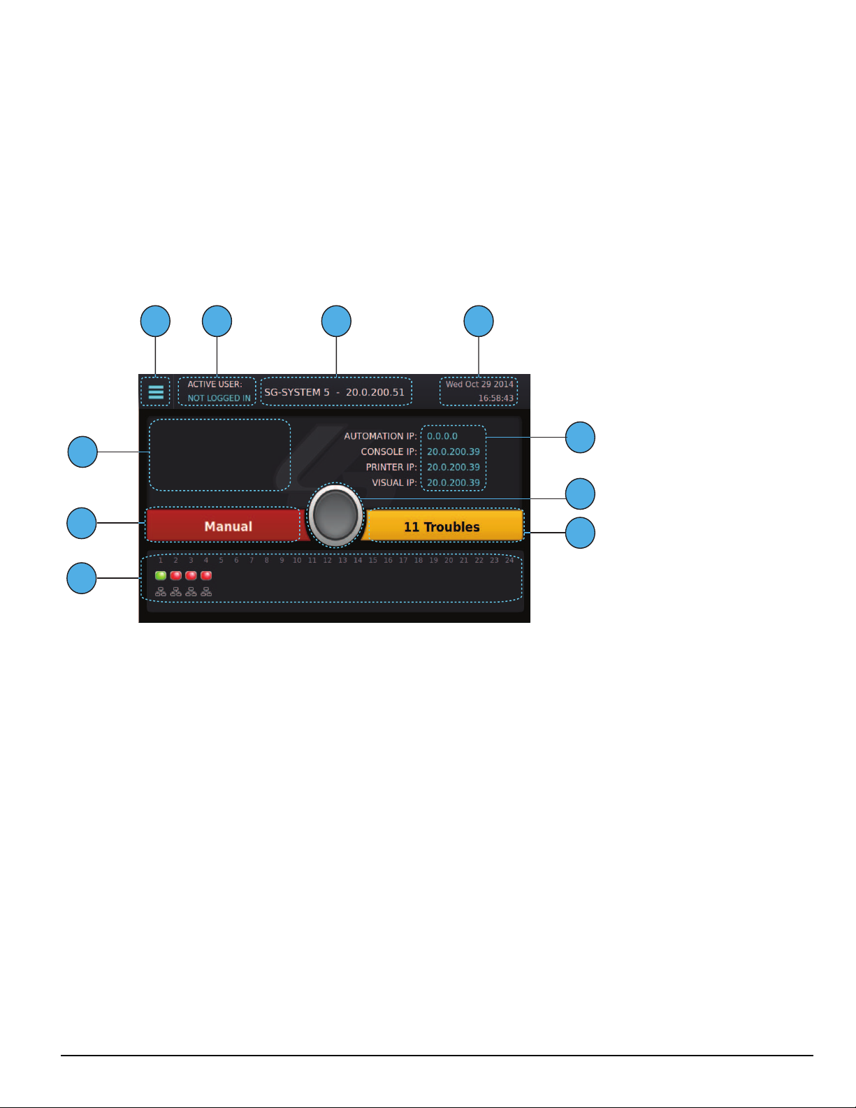
5.0 Operation
3 4
1
5
6
7
9
10
8
2
5.5.3 Home screen
The Home screen displays the overall state of the SG-CPM5 and line cards including:
1. Menu button
2. Active user
3. Title with the unit IP
4. Time and date
5. IP addresses of computers connected to the SG-CPM5
6. ACK button
7. Trouble status
8. Line card status
9. Status banner (ACTIVE/MANUAL/STANDBY)
10. User defined messages
After 60 seconds without user activity, all user and administrator screens (except for the Hardware Diagnostics screen) time out and jump to the Home
screen.
5.5.3.1 Status banner
The Status banner displays whether the SG-CPM5 is in Active, Manual, or Standby mode and which automation slot is currently outputting to displayed SG-TCP, SG-SERIAL or SG-ALL.
This banner is displayed in reduced size on other user screens.
5.5.3.2 Type - unit IP
The upper middle of the screen displays the type of System and the SG-CPM5's IP address. For the SG-System 5, it displays “SG-SYSTEM 5 X.X.X.X”
5.5.3.3 Active mode
The SG-CPM5 is Active when sending signals to automation. In this mode, the Status banner displays "Active" and the color of the banner is blue.
5.5.3.3.1 SG-TCP
The Status banner displays SG-TCP when it is currently outputting the signals to the TCP port.
5.5.3.3.2 SG- SERIAL
The Status banner displays SG-SERIAL when it is currently outputting the signals to the serial port.
- 53 -
Page 54

5.0 Operation
5.5.3.3.3 SG-ALL
The Status banner displays SG-ALL when Option [401] is set to ALL Mode where the signals are outputted to TCP and SERIAL.
5.5.3.4 Standby mode
When the SG-CPM5 is not active, it is in Standby mode. In this mode, the Status banner displays "Standby" and the color of the banner is blue.
5.5.3.5 Manual mode
The SG-CPM5 is in Manual mode when not sending signals to automation software and when not the standby SG-CPM5.
When in Manual mode, the status banner displays "Manual" and the color of the banner is red. The number of pending events requiring acknowledgment are displayed in this banner.
If acknowledgment events are pending, the ACK button, along with the status and trouble banners, slide over the line card widget. The pending events
are displayed where the user defined message and IPs were displayed. When an incoming alarm arrives, the buzzer sounds and the ACK button flashes.
If more events are present than can be displayed on the screen, a scroll bar is displayed to the right. Once an event is acknowledged, the display returns
to the top of the list.
A user must be logged in to acknowledge events.
On screens other than the Home screen, a red flashing ACK condition is shown via a flashing red screen border.
5.5.3.6 System trouble
The Trouble banner indicates the presence of system troubles and is located on the right of the Home screen beside the ACK button. If pending alarms
require acknowledgment, and the SG-CPM5 is in Manual mode, this bar covers the line cards.
While not on the Home screen, this banner remains visible in reduced size. The color of the banner is the same as on the Home screen.
5.5.3.6.1 No troubles
If no system troubles are present, the banner displays “No Troubles” and the color of the banner is green.
5.5.3.6.2 Troubles
If system troubles are present, the banner displays “X Troubles,” where X is the number of system troubles. The color of the banner is yellow.
- 54 -
Page 55

5.0 Operation
5.5.3.6.3 Trouble screen
The Trouble Status screen displays the current list of SG-CPM5 troubles, including problems with the power supplies, batteries, fans, printers, etc. To
navigate to the Trouble Status screen, either click on the Trouble banner or click the menu and then Trouble Status.
Scroll arrows provide access to the next or previous page of troubles.
5.5.3.7 Line Card banner
The Line Card banner displays the line cards being polled by the SG-CPM5. This banner displays the type of line card (indicated by an icon), as well as
the status of the line card (indicated by color).
If the SG-CPM5 is in Manual mode and alarms are pending acknowledgment, the Status banner, ACK button, and Trouble banner slide down and the
Line Card banner disappears.
5.5.3.7.1 Numbering
The slot number of each SG-DRL5-IP (1-24) is displayed at the top of the Line Card banner.
5.5.3.7.2 Icons
The following icons indicate the type of line card and the status:
DRL5-IP icon
DRL5-2L icon
DRL5/DRL5E icon
Line card slot not polled – no icon – background color
Line card absent. The icon is in the middle of the display and there is no line card icon with it just the red orb.
Line card polled by other CPM. To be used for Split Reporting mode only – when the two CPMs are sharing the polling of cards. The icon is in
the middle of the display and there is no line card icon with it just the purple orb.
5.5.3.7.3 Status color
SG-DRL5-IP
The mode and/or network speed of each line card is indicated by the color above and below the line card icons.
The status color indicates the mode and/or network speed:
SG-DRL5-IP
- 55 -
Page 56

5.0 Operation
Blue OK and 1GB/s network
Green OK and 100Mb/s network
Orange OK and 10Mb/s network
Red Network Fault
No status received or no communication from the line card. Unless the line card status changes, this indicator disappears within one
Grey
minute.
Yellow Busied out
Purple Decommissioned
SG-DRL5/DRL5E/DRL5-2L
Color Description Icon DRL5/DRL5E (single line card) Icon DRL5-2L
Green Phone line 1 and 2 are present
Red Phone line 1 and 2 are absent
Yellow System trouble present/busy out
Green/red
Red/green
Line 1 is present
Line 2 is absent
Line 1 is absent
Line 2 is present
NA
NA
5.5.3.8 IPs
Four IPs are displayed above the Trouble banner: Automation IP, Console IP, Printer IP and Visual IP. These IPs are hidden if the system is in Manual
mode with pending alarms to be acknowledged.
5.5.3.8.1 Automation IP
This displays the IP address of the automation computer connected to the automation port of the SG-CPM5. Depending on the system configuration
there may be up to four automation IP addresses listed.
5.5.3.8.2 Logging IP
This displays the IP address of the logging automation computer connected to the automation port of the SG-CPM5.
NOTE: The logging port is a licensed feature and requires purchase of the SG-CPM5-LOG license.
5.5.3.8.3 Console IP
This displays the IP address of the SG-System 5 Console Server installed on the Console port of the SG-CPM5.
The Console port of the SG-CPM5 is 1024.
- 56 -
Page 57

5.0 Operation
5.5.3.8.4 Printer IP
This displays the IP address of the SG-System 5 Console Server or third party printer software installed on the Printer port of the SG-CPM5. The
printer port of the SG-CPM5 is 1027.
5.5.3.8.5 Visual IP
This displays the IP address of the SG-System 5 Console Server or third party visual verification software installed on the visual verification port of the
SG-CPM5. The visual verification port of the SG-CPM5 is 2025 (default value).
5.5.3.9 Time and date
The time and date is displayed at the upper right of the screen in the format:
Mon Jun 17 2013
12:30:40 PM
5.5.3.10 Active user
This displays the user currently logged in.
5.5.3.11 User defined message
User defined messages are displayed below the active user.
5.5.3.12 ACK button
The ACK button is displayed in the middle of the Home screen. When the SG-CPM5 is in Active, Standby or Manual mode with no pending alarms to
be acknowledged this button is gray. When the system is in Manual mode with pending alarms, this button slides down to enable the user to record the
alarm and then press the ACK button to acknowledge the top event.
5.5.3.13 Menu button
The Menu button at the top left opens a menu that enables navigation to the Home screen, LOGIN/Options, Trouble Status, Hardware Diagnostics and
Back.
This menu is accessible at all times except when the system is in Manual mode with pending alarms to be acknowledged.
5.5.3.14 Home button
The Home button, located below the LCD screen, returns the display to the Home screen. This is the physical button below the LCD screen.
- 57 -
Page 58

5.5.4 Logging In
5.5.4.1 Login/Options
This screen provides access to username and password entry.
5.0 Operation
5.5.4.2 Username
The text box on the left is for the username. The username must be 1-8 characters long and can contain A-Z, a-z, 0-9 and space. The username cannot be
only a space.
5.5.4.3 Password
The text box on the right is for the password. The password must be 8-20 characters long and can be A-Z, a-z, 0-9.
Click the Eye icon inside the text box to show the password characters as they are typed. By default, characters are hidden and each character appears as
* (asterisk).
5.5.4.4 Default username and password
Administrator – User 1
Username : Admin
Password : adminpass
User 2-16
Username : User [X]
Users 2-16 do not have passwords. Assign a password with the LCD or Console using the admin login.
Coldboot – Login to coldboot the system
Use this login to set the options back to default if the admin password is lost.
Username : Coldboot
Password : resetoption
5.5.4.5 Keyboard
Use the keyboard at the bottom of the screen to type a-z and 0-9. Press the Shift key to change to capitals for the next letter typed. Press and hold the
Shift key for caps lock. Press the Shift key again to remove caps lock.
FIGURE 5-1: Shift Key
- 58 -
Page 59

5.0 Operation
5.5.4.6 Valid username and password
When a valid user name and password are used, pressing the submit button displays the Main Menu.
5.5.4.7 Invalid username and password
If the username and the password are invalid, pressing the submit button displays an error message.
If an invalid username and password combination is entered six times, the system returns to the Home screen. The Login screen is locked out for one
minute.
- 59 -
Page 60

5.0 Operation
5.5.5 Hardware Diagnostics
The Hardware Diagnostics screen enables the user to view the current fan speeds, temperatures and power consumption of the receiver.
5.5.5.1 Fan Speed tab
The Fan Speed screen displays the current fan speed of the receiver. The color of each of the up to six gauges changes from green to yellow to red as
fan speed increases. The readings are shown in RPM. The gauges for CPM 1(primary) and CPM 2 (secondary), and Fan Tray 1 and 2 are displayed by
default. To view the other fan trays, scroll using the arrow button.
5.5.5.2 Temperatures tab
The Temperature screen displays the current temperature of each SG-CPM5. Each gauge changes color from green to yellow to red as the temperature
increases. The readings can be displayed in either Celsius or Fahrenheit, and are received approximately every five seconds. Both positive and negative
readings are shown.
Temperature Alert Thresholds:
l 65°C/149°F - Normal state to Warning (generates temperature warning on printer/automation):
l 95°C/203°F - Warning to Alarm (generates temperature alarm on printer/automation):
l 55°C/131°F - Warning to normal (generates temperature restore on printer/automation):
l 85°C/185°F - Alarm to Warning (generates temperature warning on printer/automation):
- 60 -
Page 61

5.0 Operation
5.5.5.3 Power Consumption screen
The Power Consumption screen displays the power used by the system in real time as well as the maximum total allowed. The usage bar provides a
graphical indication of power consumption and changes color from green to yellow to red as the maximum is reached. At that point, a PSU5 trouble is
output to printer/automation.
5.5.6 Admin Menu screen
This screen can only be accessed if the user logs in as User 1 (Admin).
The Admin Menu provides access to SG-CPM5 options, Date & Time, System Information, Brightness/Tone, Reset SG-CPM5 and More Options.
5.5.7 Admin access versus user access
User 1 is the admin and users 2-16 are users. The admin has access to all the menus in the Admin Menu screen while users only have access to the
View Options, Date & Time and System Information.
- 61 -
Page 62

5.0 Operation
5.5.7.1 CPM Options
This section provides access to View Options, Change Options, and Cold Boot CPM.
5.5.7.2 View Options
The View Options screen displays a list of system information. Use the scroll bar on the right to view all options.
- 62 -
Page 63

5.0 Operation
5.5.7.3 Change SG-CPM5 options
This screen is used to change SG-CPM5 options. Use the scroll bar on the right to access all SG-CPM5 options.
Click on an option to change it. The current value and the appropriate keyboards are displayed.
To save a change, press the Save button. To cancel the changes, press the Cancel button.
If a change requires a reset, a pop-up is displayed when the user exits the Main Menu or goes back to the Home screen. If reboot later is selected, a red
reset icon appears beside the time indicating that the user must reboot for the changes to take effect.
5.5.7.4 Full Keyboard options
A full keyboard is provided for options requiring alphanumeric entry. To save changes, press the Save button. The Save button turns red if the entry is
invalid. Press the Shift key to capitalize the next character typed. Press and hold the Shift key to enable or disable caps lock. When caps lock is enabled,
all letters are entered in uppercase.
- 63 -
Page 64

5.0 Operation
5.5.7.5 Numeric Keyboard options
A reduced keyboard is provided for options that require only numbers and/or hex characters. Users can enter a value from 0-9, and A-F. To save
changes, press the Save button. To cancel and go back to the Change Options screen, click either Back or Cancel.
5.5.7.6 Selectable options
Options with limited input choices are provided with the appropriate options to select from. To save changes, press the Save button. To cancel and go
back to the Change Options screen, click either Back or Cancel.
- 64 -
Page 65

5.0 Operation
5.5.7.7 Cold Boot SG-CPM5
This changes the options back to default and will require a reset.
When Cold Boot CPM is selected, the following prompt is displayed: “This will restore CPM options to default. Restore now?”
To restore the SG-CPM5 options to default press the YES button. The CPM5 reboots. To cancel, press the NO button.
5.5.7.8 Set Date Time
This screen is used to change the system date and time.
To change a value, click on it to change the color to blue then press the up/down arrows to select a value.
To change the value faster, hold the up/down arrow.
To save the date and time, press Set.
To cancel, press Back.
- 65 -
Page 66

5.0 Operation
5.5.7.9 System Info
This screen displays information for the SG-CPM5. Use the scroll bar on the right to view all data. Press Back to go back to the previous screen.
5.5.7.10 Brightness/Tone
The Brightness/Tone screen is used to adjust the brightness of the LCD and the tone frequency of the buzzer. Changes only take effect when the slider
is released. Brightness settings range from 1 (dimmest) to 100 (brightest). Nine tone settings are available ranging from 1 (1.49KHz) to 8 (4.54Khz). A
setting of 0 mutes the tone.
- 66 -
Page 67

5.0 Operation
5.5.7.11 Reset SG-CPM5
This option resets the SG-CPM5. The following prompt is displayed: “This will reset the CPM. Reset now?”
Select YES to reset the SG-CPM5 or NO to cancel.
5.5.7.12 SG-CPM5 decommission
This option performs a decommission of the CPM. The following prompt is displayed: "Warning, some of the option changes require a decommission!
Do you wish to do it now?".
- 67 -
Page 68

5.0 Operation
5.5.7.13 More options
This screen is an extension of the Main menu and displays selections for Debug Mode and Visual Display Test.
5.5.7.14 Debug Mode
This screen displays the automation output from the receiver on either the TCP port of 1025 or the serial automation port and should only be used for
troubleshooting purposes. A test message can be sent to the automation software. Only the last 500 events are displayed.
- 68 -
Page 69

5.0 Operation
5.5.7.15 Visual Display Test
Use this screen to perform a visual display test. The following prompt is displayed: “This will perform a Visual Display Test. Begin the test now?”
Press YES to start the test. Press NO to cancel.
When the test is performed, the screen changes to white, the LEDs of all the line cards and the SG-CPM5 turn on, and the buzzer activates. The test lasts
for approximately five seconds. If this test is performed on the standby CPM5, the line card LEDs do not light steady as only the Active/Manual CPM
is communicating to the line cards.
5.5.8 User menu
This screen can only be accessed if the user logs in as a user or user 2-16. View Options are available for Date & Time and System Information.
5.5.8.1 View Options
This screen is used to view options. Use the scroll buttons to view all options.
- 69 -
Page 70

5.0 Operation
In this screen the passwords are not visible and appear as **********
NOTE: For details on the Date & Time or the System Information, "5.5.7.8" and "5.5.7.9".
- 70 -
Page 71

6.0 Options
In this chapter...
6.1 SG-CPM5 options 72
6.1.1 SG-CPM5 options: [0XX] - IP options 72
6.1.2 SG-CPM5 Options: [1XX] - User Name/Password Options 72
6.1.3 SG-CPM5 Options: [2XX] - System Options 73
6.1.4 SG-CPM5 Options: [3XX] - LCD Options 74
6.1.5 SG-CPM5 Options: [4XX] - Automation Options 74
6.1.6 SG-CPM5 Options: [5XX] - Printer Options 82
6.1.7 SG-CPM5 Options: [6XX] and [7XX] - Troubles 83
6.2 SG-DLR5-IP Options 86
6.2.1 SG-DRL5-IP Options: [1XX] - System Hardware 86
6.2.2 SG-DRL5-IP Options: [2XX] - Signaling Options 88
6.2.3 SG-DRL5-IP Options: [3XX] - System Troubles 89
6.2.4 SG-DRL5-IP Options: [4XX] - System Options 90
6.2.5 Profile Options 98
Page 72

6.0 Options
6.1 SG-CPM5 options
6.1.1 SG-CPM5 options: [0XX] - IP options
These sections contain options related to IP addresses.
Option [001]: IP Address
Default (0.0.0.0) - DHCP
This section is the IP address of the SG-CPM5. The IP Address is entered as a dotted decimal number. Example: 192.168.002.045. Each segment of the
IP address has a valid range from 000 to 255. The default of 0.0.0.0 sets the IP as DHCP.
NOTE: The unit must be reset before parameter changes take effect.
Option [002]: Subnet Mask
Default (255.255.0.0)
This section is the subnet mask of the SG-CPM5. The subnet mask is entered as a dotted decimal number. Example: 255.255.000.000. Each segment of
the subnet mask has a valid range from 000 to 255.
If section [001] is set to 0.0.0.0, the SG-CPM5 uses the Subnet Mask from the DHCP server.
NOTE: The unit must be reset before parameter changes take effect.
Option [003]: Gateway Address
Default (0.0.0.0)
The gateway address is the IP address of the router used in the event that the data being sent is not on the same network as the SG-CPM5. The gateway
address is entered as a dotted decimal number. Example: 192.168.002.001. Each segment of the gateway address has a valid range from 000 to 254.
If section [001] is set to 0.0.0.0, the SG-CPM5 uses the Gateway from the DHCP server.
NOTE: The unit must be reset before parameter changes take effect.
6.1.2 SG-CPM5 Options: [1XX] - User Name/Password Options
These sections are used to change user names and passwords needed to access the programming menu and console connection. Sixteen users accounts
are available. User 1 is the Administrator, while users 2 through 16 are assigned to individual operators. The Administrator can access all menus. Other
user accounts are limited to read-only access.
Option [101]: User#1 (Admin) User Name
Default (Admin)
This section is the user name of the Administrator. Valid user names are between 1 and 8 characters, case-sensitive and can be composed of numbers,
spaces, and upper/lower-case letters. User names cannot begin with a space.
Option [102]: User#1 (Admin) Password
Default (adminpass)
This section is the password for the Administrator. Valid passwords are between 8 and 20 characters and can be composed of numbers and upper/lower-case letters. Passwords cannot contain any spaces.
Options [103], [105], [107], [109], [111], [113], [115], [117], [119], [121], [123], [125], [127], [129] and [131]: User Names 2-16
Defaults (User 2) - (User 16)
These sections are the user names of individual users. Valid user names are between 1 and 8 characters, case-sensitive and can be composed of numbers, spaces, and upper/lower-case letters. User names cannot begin with a space.
Options [104], [106], [108], [110], [112], [114], [116], [118], [120], [122], [124], [126], [128], [130] and [132]: User Passwords 2-16
Defaults (AAAAAAAA)
These sections are the passwords of individual users. Valid passwords are between 8 and 20 characters and can be composed of numbers and upper/lower-case letters. Passwords cannot contain any spaces.
- 72 -
Page 73
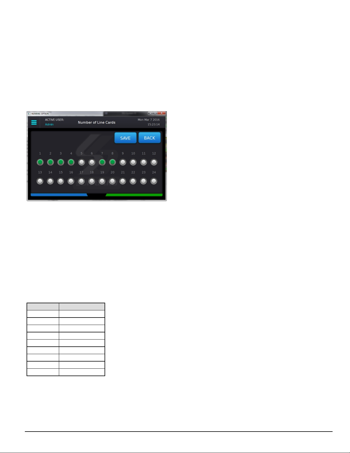
6.0 Options
6.1.3 SG-CPM5 Options: [2XX] - System Options
Option [201]: Number of Line Cards
Default (24 line cards)
This option is used to set the number of line cards polled by the CPM. This value is a bit mask representing the line card slots that are monitored for line
cards.
For this option, the list view displays the number of bits as the number of line cards.
For example, if the system has four PSTN cards and two IP cards, program the options as 1, 2, 3, 4, 7, and 8. All the other slots are ignored. In this
example, the CPM ignores all but six slots because six line cards are enabled.
FIGURE 6-1: Option [201] programming mode
"FIGURE 6-1" shows the programming mode for the option. You can select the slots that you want to be active. Active slots are indicated by a green
circle and disabled slots are indicated by a gray circle. The number of line cards shown is the total number of bits for the shelf. In "FIGURE 6-1" there
are six active cards.
You can install line cards in any order but you must group them by the physical size of the cards. For example, group DRL5-2L cards in a bank of six
because you must remove the fan tray before you install these cards.
NOTE: The CPM only polls the programmed slots. It ignores all the other slots.
NOTE: The active CPM is the master and it is responsible for all line card polling.
Option [202]: Buzzer Tone
Default (6)
This option is used to set the tone of the buzzer that sounds when the system receives an alarm and is not able to forward the alarm message to automation (Serial or TCP/IP). If set to ‘0’, the buzzer does not sound when the SG-CPM5 is in Manual mode and alarm messages are pending.
NOTE: For UL installations, setting the buzzer tone to ‘0’ is not permitted.
Option Value Buzzer Frequency
0 NONE/OFF
1 1.49KHz
2 1.99KHz
3 2.10KHz
4 2.65KHz
5 3.15KHz
6 3.97KHz
7 4.27KHz
8 4.54KHz
Option [205]: Temperature Format
Default (00)
This option controls the format of any temperature displayed on the LCD.
Celcius (00) - Temperature is displayed as Celsius.
Fahrenheit (01) - Temperature is displayed as Fahrenheit.
- 73 -
Page 74

6.0 Options
6.1.4 SG-CPM5 Options: [3XX] - LCD Options
Option [301]: Brightness Control
Default (50)
This option controls the brightness of the LCD touchscreen. Valid entries are from 1 to 99, where 1 is the least bright and 99 is the brightest. In order to
avoid selecting a value that cannot be seen, Sur-Gard recommends using the Brightness/Tone menu.
6.1.5 SG-CPM5 Options: [4XX] - Automation Options
These sections are used to configure automation options. For Visual Verification (via the Advanced Output Protocol), the SG-Automation output follows the active SG-CPM5. This means that even if SG-Automation is in Manual mode, the SG-CPM5 continues to output signals for the Advanced
Output Protocol.
Option [401]: Automation Mode
Default Auto IP Fallback(4)
The TCP/IP connection is the primary output of automation alarms. Sockets appear and disappear as processes are terminated and initiated. After socket
loss, automation output is redirected to other connections. This option controls how output is redirected if a connection fails.
NOTE: The unit must be reset before parameter changes take effect.
Loop (0)
The active SG-CPM5 uses TCP/IP at start-up. The unit automatically loops between TCP/IP and serial if failure is detected. If neither TCP/IP nor serial
are present, the SG-CPM5 switches to Manual mode. In Manual mode, the standby SG-CPM5 only takes over if the active/manual SG-CPM5 fails or
is rebooted
Fallback (1)
If both outputs are present, the active SG-CPM5 uses TCP/IP until it fails then switches to serial. The SG-CPM5 does not switch back to TCP/IP mode
until a reset fallback command is received from the console. If neither TCP/IP nor serial are present, the SG-CPM5 switches to manual mode. In manual
mode, the standby SG-CPM5 only takes over if the active/manual SG-CPM5 fails or is rebooted.
All Mode (2)
The active SG-CPM5 always sends to all connected outputs. If at least one output replies with an ACK, the alarm is considered to be transmitted,
whether the other output acknowledged it or not. This setting is NOT recommended. If neither TCP/IP nor serial are present, the SG-CPM5 switches to
manual mode. In manual mode, the standby SG-CPM5 only takes over if the active/manual SG-CPM5 fails or is rebooted.
IP Fallback Mode (3)
At start-up, the primary SG-CPM5 sends through the TCP/IP output.
If the primary SG-CPM5 TCP/IP output fails, the secondary SG-CPM5 sends through the TCP/IP output.
If the secondary SG-CPM5 TCP/IP output fails, the primary SG-CPM5 sends through its serial output.
If the primary SG-CPM5 serial fails, the secondary SG-CPM5 sends through the serial output.
If neither TCP/IP nor serial are present, the SG-CPM5 switches to manual mode.
The SG-CPM5 does not switch back to TCP/IP mode until a reset fallback command is received from the console or the serial fails.
Automatic IP Fallback (4)
This mode is similar to Fallback except that when the TCP/IP connection is restored, the SG-CPM5 automatically returns to the TCP/IP output to send
events. This eliminates the need for a reset fallback command from the console.
Split Reporting Mode
Each CPM is responsible for all functions of the cards that it polls, monitoring of card status, and signal output (SG-Automation, Printer, SG-Advanced
Automation, options, commissioning/decommissioning). The two CPMs need to negotiate for power management.
When enabled, line cards are split by odd numbers to CPM1 and even to CPM2. For example, in a system that has five line cards (slots 1-5) then line
cards 1, 3, 5 are polled by CPM1, and line cards 2 and 4 are polled by CPM2. When the line cards being polled are not sequential, the even/odd rule still
applies. For example, if polling five line cards in slots 1, 2, 3, 7, and 8, then CPM 1 polls line cards 1, 3 and 7, and CPM 2 polls line cards 2 and 8.
In the case of failure of a CPM, the other CPM takes over polling and output of all signals for all line cards. When the CPM failure clears, the polling of
the cards automatically resumes the split reporting.
- 74 -
Page 75

6.0 Options
Valid Setting for Option 401
Upper Nibble Lower Nibble Function
0 0 Loop Mode
0 1 Fallback Mode
0 2 All Mode
0 3 IP Fallback Mode
0 4 Automatic IP Fallback Mode
1 0 Loop Mode - Split Report
1 1 Fallback - Split Report
1 2 Invalid Selection – mode will be placed back to Default (04)
1 3 Invalid Selection – mode will be placed back to Default (04)
1 4 Automatic IP FallBack - Split Report
- - Any other value shall force the mode back to Default (04)
For example, setting option 401 to 10 (0001 0000) enables the Split Reporting function and Loop mode. The programming option can be viewed as an
option list in the programming menu.
Automation Mode diagrams
FIGURE 6-2: Flow diagram for Loop Mode (0)
- 75 -
Page 76

FIGURE 6-3: Flow diagram for Fallback Mode (1)
6.0 Options
- 76 -
Page 77

FIGURE 6-4: Flow diagram for All Mode (2)
6.0 Options
- 77 -
Page 78

FIGURE 6-5: Flow diagram for IP Fallback Mode (3)
6.0 Options
- 78 -
Page 79

FIGURE 6-6: Flow diagram for Auto IP Fallback (4)
6.0 Options
Option [402]: COM1 (Automation) Baud Rate
Default (9600)
Determines the baud rate at which the SG-CPM5 communicates to the automation software via serial automation port. Valid selections are: 1200, 2400,
4800, 9600, 19200, 38400, or 57600.
NOTE: The unit must be reset before parameter changes take effect.
Option [403]: COM1 Data Bits
Default (8)
Determines the number of data bits used to communicate to the automation software via serial automation port. Valid selections are: 7 or 8.
NOTE: The unit must be reset before parameter changes take effect.
Option [404]: COM1 Parity
Default (0) - None
Determines the parity of the automation serial port.
Numeric Setting Display Description
0 None no parity (default)
1 Odd odd parity
2 Even even parity
NOTE: The number of stop bits cannot be changed and is always 2.
NOTE: The unit must be reset before parameter changes take effect.
Option [408]: Receiver Number
Default (01)
This is used to identify the receiver when communicating to the TCP/IP automation, serial automation and the printer. To change the receiver number,
enter a hexadecimal number from "01" to "FE." Receiver Number applies to all traffic unless overridden by other options.
- 79 -
Page 80

6.0 Options
Option [409]: Output RRLLL Digits
Default (5)
Indicates the number of digits the SG-CPM5 sends in the header to the automation output. This should be left as 5 unless the automation software does
not support MLR2000 or System III output protocol. This affects both internal SG-CPM5 and DRL5-IP messages. The valid range is from 03 to 09,
for example:
03 is RRL
09 is RRLLLLLLL
Option [410]: Protocol ID
Default (0) - 0RRLLL
When this option is programmed as 0RRLLL(0), the SG-CPM5 outputs its internal messages in the following format:
0RRLLL[#AAAA|Nxxyy]
When this option is programmed as SRRLLL(S), the SG-System 5 outputs its internal messages in the following format:
SRRLLL[#AAAA|Nxxyy]
S,0 (zero): protocol ID
RR: Receiver number
LLL: Line number
AAAA: Account code, always 0000
Nxxyy: SIA event
Option [411]: Heartbeat Timer
Default (30)
This timer determines how often a heartbeat transmission is sent to automation. The heartbeat transmission is used to ensure communications through
serial and TCP/IP are functioning normally when the receiver has no traffic. Any traffic from the receiver resets the heartbeat timer. The heartbeat is only
sent if no other signals are received during the timer’s countdown.
Enter a value, in seconds, from 01 through 99 to set the time interval between heartbeat transmissions. Enter 00 to disable heartbeat transmission.
NOTE: When 00 is used, heartbeats are not sent to automation software - this results in the connection to the automation software being
unmonitored.
NOTE: For UL listed products, 00 is not permitted.
Option [412]: ACK Wait
Default (40)
Determines how long the SG-CPM5 waits for acknowledgment on an automation output before retransmitting. Enter a value, in tenths of a second,
from 40 (4.0 seconds ) to 99 (9.9 seconds).
NOTE: The unit must be reset before parameter changes take effect.
Option [413]: B32 Headers
Default (Disabled)
Compatible with MAS B32 automation software through TCP/IP. B32 Headers apply only to TCP/IP automation messages, not serial or printer messages. When enabled, all outgoing and incoming automation messages contain four extra bytes at the start of each packet.
These four bytes are:
00 00 LL LL
Where:
LL LL = is the BCD value of the size of the entire packet.
For example, if the original length was 1B HEX bytes, the packet would be:
00 00 00 31 <original packet>
The ACK back to the receiver would be:
00 00 00 05 06
NOTE: The ACK back to the SG-CPM5 ("30 30-30 35 06" ASCII) is at the end of the packet.
NOTE: The unit must be reset before parameter changes take effect.
Option [414]: Automation Update Time & Date
Default (Disabled)
This option allows the SG-CPM5 to receive time and date updates, from automation that supports this feature, via the TCP/IP port. If the SG-CPM5
fails to get the time and date within a 24 hour period, a status message is sent to the printer and automation, following the internal trouble protocol. The
- 80 -
Page 81

6.0 Options
trouble status on the SG-System 5 is not affected. The receiver console time update function must be disabled when using this feature to ensure that the
SG-CPM5 remains synchronized with the automation PC.
Printer message: "Time&Date Update Fail"
Automation message: 0RRLLL[#0000¦NRU0000]
Option [415]: SG-TCP Automation Port # 1
Default (1025)
This section allows the SG-TCP Automation port #1 to be changed. The Automation TCP port is the port that the automation would connect to. Programmable values are from 0001-65535 (0001-FFFF).
This port is available regardless of the license configuration for Multi-port Automation.
Multi-port Automation
Each CPM can have up to four SG-TCP automation port connections. The number of ports available by license (each port is a purchase). If the license
is not enabled for the extra ports (ports 2-4), then the ports do not respond to any connection request.
There are licenses for the number of ports to be used (maximum of four) per CPM (existing port 1025 and three others unlocked by license).
The connection status of all automation ports is sent to the SG-System 5 Console.
Rules for Multi-port signal output
1. Each port connection to the automation software is monitored individually.
2. When enabled, the communication of signals from the ports is in a round robin (circular) format. Meaning, assuming all four ports are enabled, the
first signal is sent over port #1, followed by #2, #3 and #4, the fifth signal returns to #1.
3. Only if a port is busy (waiting ACK or disconnected etc.), does the CPM advance to the next port.
4. If a line card has a pending event ACK, another event can not be outputted until it is cleared (ACK received or NACK’d 26 times).
5. All ports must send a heartbeat if no traffic following heartbeat timer (option 411). There is only 1 heartbeat time for the system.
Limitations
Messages that have multiple parts are not necessarily be outputted on the same automation port. It is up to the automation software to correctly combine
the signals received. For example, Caller ID and the Automation signal - Caller ID to port 1 but event goes to port 3.
Option [416]: SG-TCP Automation Port # 2
Default (1126)
This section allows the SG-TCP Automation port #2 to be changed. The Automation TCP port is the port that the automation can connect to. Programmable values are from 0001-65535 (0001-FFFF).
This port is only available for connection when the correct license configuration for Multi-port Automation is applied.
Option [417]: SG-TCP Automation Port # 3
Default (1127)
This section allows the SG-TCP Automation port #3 to be changed. The Automation TCP port is the port that the automation can connect to. Programmable values are from 0001-65535 (0001-FFFF).
This port is only available for connection when the correct license configuration for Multi-port Automation is applied.
Option [418]: SG-TCP Automation Port # 4
Default (1128)
This section allows the SG-TCP Automation port #4 to be changed. The Automation TCP port is the port that the automation can connect to. Programmable values are from 0001-65535 (0001-FFFF).
This port is only available for connection when the correct license configuration for Multi-port Automation is applied.
Option [449]: Logging Automation Port
Default (1140)
This section allows the SG-TCP Logging Automation port to be changed. The Logging Automation port is the port that the automation can connect to.
Programmable values are from 0001-65535 (0001-FFFF).
This port is only available for connection when the correct license configuration for Log Only Automation is applied.
SG-TCP Logging Automation Rules of operation
a. The logging port clones all SG-automation signals to a this port.
b. This port does not impact the automation mode of the receiver if present/absent. Meaning that if all standard SG-Automation paths (TCP or Serial) are
absent and the logging port is present, then the automation mode is manual.
i. If the SG-Automation port is in manual mode, then all signals to the logging port are stopped (if they have not been outputted to a standard automation output).
ii. The logging port output automation signals once they have been outputted to either the SG-Serial or SG-TCP automation connection.
- 81 -
Page 82

6.0 Options
iii. The logging port is a TCP only connection (no serial port support).
iv. Only ACK required is the TCP ACK (automation ACK can be there, but is not required).
c. NACK on this port
i. Signal NACKs are ignored and move to the next signal.
d. NACK of signals on the SG-Automation connection causes a repeated message to be sent to the SG-TCP Logging port.
e. The logging port does not support the time/date update automation response – if received, it must be ignored.
f. If multi port option is enabled on the system, all SG-Automation signals from any of the enabled ports are sent to the logging port.
Option [450]: Visual Verification Automation TCP Port
Default (2025)
This section sets the visual verification automation TCP port. The visual verification automation TCP port is the port that automation or the SG-System
5 Console connects to.
6.1.6 SG-CPM5 Options: [5XX] - Printer Options
Option [501]: Printer Mode
Default (Loop)
Printer outputs can be configured in a similar manner to automation outputs except that the only acceptable values are either LOOP (00) or ALL (02).
Setting the printer mode to ALL transmits the printer message to all active ports. The first acknowledgment received is used to process the next printer
message. Setting the Printer Mode to LOOP operates similar to the Automation mode LOOP, whereas it outputs to TCP/IP. If TCP/IP fails, it outputs
to Serial. If Serial fails, it outputs to TCP/IP, etc.
NOTE: Order of sequence is TCP then serial. Sur-Gard does NOT recommend changing the default setting unless using more than one
printer.
NOTE: The unit must be reset before parameter changes take effect.
Option [502]: Serial Printer 1 Format
Default (Disabled)
This section enables the serial handshake protocol that the SG-CPM5 uses to send signals to the device (printer or terminal) connected to the serial
printer port.
NOTE: The unit must be reset before parameter changes take effect.
Option [503]: Serial Printer 1 Baud Rate
Default (57600)
Determines the baud rate at which the SG-CPM5 communicates to the serial printer connected on serial printer port 1.
Valid entries are: 1200, 2400, 4800, 9600, 19200, 38400, or 57600.
NOTE: The unit must be reset before parameter changes take effect.
Option [504]: Serial Printer 1 Data Bits
Default (8)
Determines the number of data bits used to communicate to the serial printer on serial printer port 1. Choose 7 or 8 data bits.
NOTE: The unit must be reset before parameter changes take effect.
Option [505]: Serial Printer 1 Parity
Default (0)
Determines the parity of serial printer port 1
Numeric Setting Display Description
0 none no parity (default)
1 odd odd parity
2 even even parity
NOTE: The number of stop bits cannot is fixed at 2.
NOTE: The unit must be reset before parameter changes take effect.
- 82 -
Page 83

6.0 Options
Option [510]: Date Format
Default (International)
Selects the format used to represent date for printer output. Format [1] represents US format: MM/DD/YY. Format [0] represents International format:
DD/MM/YY.
Option [511]: Printer Test
Default (Enabled)
When this option is enabled, a test signal is sent to all active printer(s) at 05:00 and 17:00 hrs. This option is set to Enabled by default.
Printer message:
26 Nov 2012 16:41:25 - 26 Nov 2012-16:41:25-00/00-SG -01-000-0000--Printer Test Message
6.1.7 SG-CPM5 Options: [6XX] and [7XX] - Troubles
The following sections control the display of trouble conditions. For installations that do not have a full SG-System 5 configuration, selected troubles
can be disabled. Disabled troubles do not display.
Option [601]: CPM5 1 Fan Trouble
Default (Enabled)
This option is used to enable or disable SG-CPM5 1 fan supervision. If this option is set to ‘Disabled’, the trouble condition is not reported.
NOTE: Must be enabled for UL installations.
Option [602]: CPM5 2 Fan Trouble
Default (Enabled)
This option is used to enable or disable SG-CPM5 2 fan supervision. If this option is set to ‘Disabled’, the trouble condition is not reported.
NOTE: Must be enabled for UL installations.
Option [603]: PSU5 1 Trouble
Default (Enabled)
This option is used to enable or disable SG- PSU5 1 supervision. If this option is set to ‘Disabled’, the trouble condition is not reported.
NOTE: Must be enabled for UL installations.
Option [604]: PSU5 2 Trouble
Default (Enabled)
This option is used to enable or disable SG- PSU5 2 supervision. If this option is set to ‘Disabled’, the trouble condition is not reported.
NOTE: Must be enabled for UL installations.
Option [605]: Fan Tray 1 Trouble
Default (Enabled)
This option is used to enable or disable fan tray 1 supervision. If this option is set to ‘Disabled’, the trouble condition is not reported.
Option [606]: Fan Tray 2 Trouble
Default (Enabled)
This option is used to enable or disable fan tray 2 supervision. If this option is set to ‘Disabled’, the trouble condition is not reported.
Option [607]: Fan Tray 3 Trouble
Default (Enabled)
This option is used to enable or disable fan tray 3 supervision. If this option is set to ‘Disabled’, the trouble condition is not reported.
Option [608]: Fan Tray 4 Trouble
Default (Enabled)
This option is used to enable or disable fan tray 4 supervision. If this option is set to ‘Disabled’, the trouble condition is not reported.
- 83 -
Page 84

6.0 Options
Option [609]: UPS AC 1 Trouble
Default (Disabled)
This option is used to enable or disable UPS AC 1 input supervision. If this option is set to ‘Disabled’, the trouble condition is not reported.
NOTE: Must be enabled for UL installations.
Option [610]: UPS AC 2 Trouble
Default (Disabled)
This option is used to enable or disable UPS AC 2 input supervision. If this option is set to ‘Disabled’, the trouble condition is not reported.
NOTE: Must be enabled for UL installations.
Option [611]: UPS Battery 1 Trouble
Default (Disabled)
This option is used to enable or disable UPS Battery 1 input supervision. If this option is set to ‘Disabled’, the trouble condition is not reported.
NOTE: Must be enabled for UL installations.
Option [612]: UPS Battery 2 Trouble
Default (Disabled)
This option is used to enable or disable UPS Battery 2 input supervision. If this option is set to ‘Disabled’, the trouble condition is not reported.
NOTE: Must be enabled for UL installations.
Option [613]: SG-Serial Automation Pri - 1 Trouble
Default (Enabled)
This option is used to enable or disable SG-Serial Automation 1 supervision for the primary SG-CPM5. If this option is set to ‘Disabled’, the trouble
condition is not reported.
NOTE: Must be enabled for UL installations.
Option [615]: SG-Serial Automation Sec - 1 Trouble
Default (Disabled)
Secondary SG-CPM5 Default (Enabled)
This option is used to enable or disable SG-Serial Automation 1 supervision for the secondary SG-CPM5. If this option is set to ‘Disabled’, the trouble
condition is not reported.
NOTE: Must be enabled for UL installations.
Option [617]: SG-Serial CPM1 Printer 1 Trouble
Default (Enabled)
This option is used to enable or disable SG-CPM5 1 printer supervision. If this option is set to ‘Disabled’, the trouble condition is not reported.
Option [618]: SG-Serial CPM2 Printer 1 Trouble
Default (Enabled)
This option is used to enable or disable SG-CPM5 2 printer supervision. If this option is set to ‘Disabled’, the trouble condition is not reported.
Option [621]:SG-TCP Automation Pri - 1 Trouble
Default (Enabled)
This option is used to enable or disable SG-TCP automation port (port 1025) supervision for the primary SG-CPM5. If any of these options are set to
‘Disabled’, the corresponding trouble condition is not be reported.
Option [622]: SG-TCP Automation Pri – 2 Trouble
Default (Disabled)
This option is used to enable or disable the supervision for the SG-TCP Automation Port #2 for the Primary CPM5. If this option is set to ‘Disabled’,
the trouble condition is not reported.
- 84 -
Page 85

6.0 Options
Option [623]: SG-TCP Automation Pri – 3 Trouble
Default (Disabled)
This option is used to enable or disable the supervision for the SG-TCP Automation Port #3 for the Primary CPM5. If this option is set to ‘Disabled’,
the trouble condition is not reported.
Option [624]: SG-TCP Automation Pri – 4 Trouble
Default (Disabled)
This option is used to enable or disable the supervision for the SG-TCP Automation Port #4 for the Primary CPM5. If this option is set to ‘Disabled’,
the trouble condition is not reported.
Option [631]:SG-TCP Automation Sec - 1 Trouble
Default (Disabled)
Secondary SG-CPM5 Default (Enabled)
This option is used to enable or disable the SG-TCP automation port (port 1025) supervision for the secondary SG-CPM5. If this option is set to ‘Disabled’, the trouble condition is not reported.
Option [632]: SG-TCP Automation Sec – 2 Trouble
Default (Disabled)
This option is used to enable or disable the supervision for the SG-TCP Automation Port #2 for the Secondary CPM5. If this option is set to ‘Disabled’, the trouble condition is not reported.
Option [633]: SG-TCP Automation Sec – 3 Trouble
Default (Disabled)
This option is used to enable or disable the supervision for the SG-TCP Automation Port #3 for the Secondary CPM5. If this option is set to ‘Disabled’, the trouble condition is not reported.
Option [634]: SG-TCP Automation Sec – 4 Trouble
Default (Disabled)
This option is used to enable or disable the supervision for the SG-TCP Automation Port #4 for the Secondary CPM5. If this option is set to ‘Disabled’, the trouble condition is not reported.
Option [665]:TCP Printer Pri - 1 Trouble
Default (Enabled)
This option is used to enable or disable TCP Printer 1 (port 1027) supervision for the primary SG-CPM5. If this option is set to ‘Disabled’, the trouble
condition is not reported.
Option [675]:TCP Printer Sec - 1 Trouble
Default (Enabled)
This option is used to enable or disable TCP Printer 1 (port 1027) supervision for the secondary SG-CPM5. If this option is set to ‘Disabled’, the
trouble condition is not reported.
Option [709]:SG-TCP/IP CPM1 Visual Verification Trouble
Default (Enabled)
This option is used to enable or disable visual verification port (port 2025) supervision for the primary SG-CPM5. If this option is set to ‘Disabled’, the
trouble condition is not reported.
Option [710]:SG-TCP/IP CPM2 Visual Verification Trouble
Default (Enabled)
This option is used to enable or disable visual verification port (port 2025) supervision for the secondary SG-CPM5. If this option is set to ‘Disabled’,
the trouble condition is not reported.
- 85 -
Page 86

6.0 Options
Option [711]: SG-TCP Automation Pri - Logging Trouble
Default (Disabled)
This option is used to enable or disable the supervision for the SG-TCP Logging Port for the Primary CPM5. To monitor or report the trouble, change
this option to Enabled.
Option [712]: SG-TCP Automation Sec - Logging Trouble
Default (Disabled)
This option is used to enable or disable the supervision for the SG-TCP Logging Port for the Secondary CPM5. To monitor or report the trouble,
change this option to Enabled.
6.2 SG-DLR5-IP Options
SG-System 5 Console v2.5 (or higher) software is required for programming and communication with SG-DRL5-IP Receiver Modules.
6.2.1 SG-DRL5-IP Options: [1XX] - System Hardware
Option [101]: IP Address (IPV4)
Default (10.0.7.200)
This IP address identifies the SG-DRL5-IP on the IP network. Each node on the IP network must be assigned a unique IP. The SG-DRL5-IP can only
use Static IPs. DHCP is not supported.
Option [102]: Subnet Mask (IPV4)
Default (255.255.0.0)
A mask used to determine the subnet an IP address belongs to. The subnet is a portion of a network that shares a common address component. On
TCP/IP networks, subnets are defined as all devices whose IP addresses have the same prefix. Dividing a network into subnets is useful for both security and performance reasons.
Option [103]: Gateway Address (IPV4)
Default (0.0.0.0)
This is the address of the Gateway through which the SG-DRL5-IP must communicate to reach the transmitter. This address is applied to all modules
connected to the SG-DRL5-IP.
Option [111]: Receiver Number
Default (01)
The receiver number is used for sending signals to the central station software. Refer to the manuals for any central station automation software being
used to determine if this number has any special requirements. Also, ensure that no duplicate receiver numbers are used. For example, in the messages
below, the receiver numbers are in bold.
001001[#0000|NMIss00]
SG -01-001-0000-NMIss00- Firmware Update Initiated
Option [112]: Line Card Number - Channel 1
Default (01)
The line card number provides a virtual identification code for each SG-DRL5-IP module. Hexadecimal numbers “01” to “FE” can be programmed to
identify line cards. For example, in the automation/printer messages below, the line card numbers are in bold.
001001[#0000|NMIss00]
SG -01-001-0000-NMIss00- Firmware Update Initiated
Option [113]: Line Card Number - Channel 2
Default (02)
The line card number provides a virtual identification code for each SG-DRL5-IP module. Hexadecimal numbers “01” to “FE” can be programmed to
identify line cards. For example, in the automation/printer messages below, the line card numbers are in bold.
001001[#0000|NMIss00]
SG -01-001-0000-NMIss00- Firmware Update Initiated
- 86 -
Page 87

6.0 Options
Option [114]: Line Card Number - Channel 3
Default (03)
The line card number provides a virtual identification code for each SG-DRL5-IP module. Hexadecimal numbers “01” to “FE” can be programmed to
identify line cards. For example, in the automation/printer messages below, the line card numbers are in bold.
001001[#0000|NMIss00]
SG -01-001-0000-NMIss00- Firmware Update Initiated
Option [115]: Line Card Number Length
Default (0A) - 3-Digit LC num (2-Digit Receiver DEC)
This option is used to determine how many digits from the line card number are sent to the output. This option also sets whether the number appears in
hex or decimal. Program this option with one of the following:
1-HEX Digit LC num (hex) (01) Sends only one Hex digit to the printer or computer output (the last digit of the line
card number is used).
2-HEX Digit LC num (hex) (02) Sends 2-digit Hex line card number to the output.
3-HEX Digit LC num (hex) (03) Sends 3-digit Hex line card number to the output (a leading zero is inserted prior to
the line card number).
3-Digit LC num (2-Digit Receiver DEC)(0A) Sends 3-digit line card number in decimal; sends 2-digit receiver number in decimal
Option [116]: Protocol ID
Default (01) - 0RRLLL
00 - SRRLLL = Output for all internal signals is SRRL protocol
01 - 0RRLLL = Output for all internal signals is 0RRL protocol
02 - SRRLLL, Leading space (DVACS only) = Output signals in automation protocol SRRL with leading space in the zone
(DVACS only)
03 - 0RRLLL, Leading space (DVACS only) = Output signals in automation protocol 0RRL with leading space in the zone
(DVACS only)
When this option is programmed as SRRLLL(00), the SG-DRL5-IP outputs internal messages in the following format:
SRRLLL[#AAAA|Nxxyy]
If it is programmed as 0RRLLL(01), internal messages output as:
0RRLLL[#AAAA|Nxxyy]
S, 0 (zero) = Protocol number
RR = Receiver number
LLL = Line number
AAAA = Account code, always 0000
Option [123] Busy Out
Default (00) - Buffer Full, SG-CPM5 Absent, No Time or Firmware Corrupt
The line card stops acknowledging transmitter events under specific trouble conditions if option [123] is programmed with the following:
00 No time is set on the SG-CPM5, firmware corruption, the buffer is full or the SG-DRL-IP has lost communication with the SG-
CPM5.
01 SG-DRL-IP is never busied out
04 SG-DRL-IP is busied out, there is no automation or the SG-CPM5 is absent
05 SG-DRL-IP is busied out, buffer is full or the SG-CPM5 is absent
NOTE: If 01 is selected, the line card overwrites the oldest alarm with a new alarm when the internal buffer is full. For UL Listed products,
the permitted setting is 00.
The status LED indicates the following for busy conditions:
Number of Flashes Reason
Solid Internal network failed
1 flash CPM absent
2 flashes Line card is busied out
3 flashes Printer buffer full
- 87 -
Page 88

6.0 Options
Number of Flashes Reason
4 flashes Computer buffer full
5 flashes Checksum failed
Option [124]: SD Card Full
Default [00] - Disabled
This option is used to over-write old visual verification files on an SD card once it becomes full, rather than manually re-formating or replacing the card.
When disabled (00), the oldest visual verification files on the SD card are overwritten by new ones.
When enabled (01), Visual Verification signals are not acknowledged if the SD card is full. Space must be made on the SD card, either by reformatting
or replacing it, before new Visual Verification signals are acknowledged.
Option [125]: Visual Verification Film
Default [00] - Disabled
This option determines if .AVI files are generated for visual verification events.
When enabled (01), Visual Verification Film (the .AVI file) is not generated. Only the received .jpg and .wav files are saved. All required conversion of
received files is still performed (e.g., Audio up-converted to 4-bit; black and white images to colour .jpg). Enabling this option improves SD card performance.
When disabled (00), .AVI files are created and saved to the SD card, along with the associated .jpg and .wav files files.
6.2.2 SG-DRL5-IP Options: [2XX] - Signaling Options
Option [201]: Alarm Port Number - Channel 1
Default (3061), UDP
Use this option to set the alarm port connection number for the receiver. While the default value is suitable for environments involving just one receiver,
Option [201] can be used to differentiate receivers in a complex, multiple receiver environment. If this option is changed, transmitters communicating to
the SG-DRL5-IP must be programmed with the new port number. Communicators connected to the receiver send their signals to this port.
Option [202]: Alarm Port Number - Channel 2
Default (3071), UDP
Use this option to set the alarm port connection number for the receiver. While the default value is suitable for environments involving just one receiver,
Option [202] can be used to differentiate receivers in a complex, multiple receiver environment. If this option is changed, transmitters communicating to
the SG-DRL5-IP must be programmed with the new port number. Communicators connected to the receiver send their signals to this port.
Option [203]: Alarm Port Number - Channel 3
Default (3081), UDP
Use this option to set the alarm port connection number for the receiver. While the default value is suitable for environments involving just one receiver,
Option [203] can be used to differentiate receivers in a complex, multiple receiver environment. If this option is changed, transmitters communicating to
the SG-DRL5-IP must be programmed with the new port number. Communicators connected to the receiver send their signals to this port.
Option [221]: Transmitter Absent Debounce Time
Default (120)
The time, in seconds, for which a transmitter configured in supervised mode must be absent before a transmitter failure condition is reported. Valid
entries are 5-65535 seconds. The transmitter is considered absent when it hasn't received any alarm traffic or heartbeats for the duration of the transmitter absent debounce time.
This is a dynamic option and it follows the profile setting it is assigned to for the associated DNIS.
NOTE: The transmitter starts in the absent condition and must be restored before using this window.
NOTE: Transmitter Absent Time should not be less than 90 seconds. For ULC Commercial Burg Installations Security Levels A1 to A4
and ULC Commercial Fire Active communication systems, this option shall be programmed as 180 seconds. For UL Commercial
Burg Installations (standard/encrypted line security), this option shall be programmed as 200 seconds.
For UL Commercial Fire installations (single communication technology) this option shall be programmed as 300 seconds.
- 88 -
Page 89

6.0 Options
Option [222]: Transmitter Restoral Time
Default (60)
This option determines the required time a transmitter must be present before it is registered in the Account Table and the transmitter restoral message is
sent.
This is a dynamic option and it follows the profile setting it is assigned to for the associated DNIS.
NOTE: Two heartbeats must be received from the supervised IP transmitter before the register and restoral of the communicator.
For UL Listed products, the permitted setting is 90 seconds.
6.2.3 SG-DRL5-IP Options: [3XX] - System Troubles
Option [301]: Transmitter Unencrypted Trouble
Default (Enabled)
This trouble enables or disables unencrypted event reporting. When set to Enabled, the trouble is reported. When set to Disabled, the trouble is not reported. This trouble is reported when the transmitter power cycles.
Enabled Condition reported
Disabled Condition not reported
NOTE: For UL Listed products, the permitted setting is Enabled.
Option [302]: Unknown Account Trouble
Default (Enabled)
This trouble enables or disables unknown account signal reporting (not in the account table). When set to Enabled, the trouble is reported. When set to
Disabled, the trouble is not reported.
Enabled Condition reported
Disabled Condition not reported
NOTE: For UL Listed products, the permitted setting is Enabled.
Option [303]: Supervised Accounts Exceeded Trouble
Default (Enabled)
This trouble enables or disables reporting when the account table limit is exceeded by a new account trying to connect to a SG-DRL5-IP with a full
account table. When set to Enabled, the trouble is reported. When set to Disabled, the trouble is not reported.
Enabled Condition reported
Disabled Condition not reported
NOTE: The number of accounts permitted in the account table is dependent on the table size unlocked for the IP channel.
NOTE: For UL Listed products, the permitted setting is Enabled.
Option [304]: Transmitter Restore Trouble
Default (Enabled)
This trouble enables or disables reporting of a transmitter restoral condition on the line card. When set to Enabled, the trouble is reported. When set to
Disabled, the trouble is not reported..
Enabled Condition reported
Disabled Condition not reported
Option [305]: Transmitter Absent Trouble
Default (Enabled)
This trouble enables or disables reporting of a transmitter failure/absent condition on the line card. When set to Enabled, the trouble is reported. When
set to Disabled, the trouble is not reported..
Enabled Condition reported
Disabled Condition not reported
NOTE: The number of accounts permitted in the account table is dependent on the table size unlocked for the IP channel.
- 89 -
Page 90

6.0 Options
Option [306]:TX Swap Trouble
Default (Enabled)
This trouble enables or disables reporting of a transmitter swap condition on the line card. When set to Enabled, the trouble is reported. When set to Disabled, the trouble is not reported..
Enabled Condition reported
Disabled Condition not reported
Option [307]:Invalid Report Trouble
Default (Enabled)
This trouble enables or disables reporting of an invalid report condition. A received signal is invalid if it has a bad checksum or encryption key missmatch. When set to Enabled, the trouble is reported. When set to Disabled, the trouble is not reported..
Enabled Condition reported
Disabled Condition not reported
Option [308]:Transmitter Deleted Trouble
Default (Enabled)
This trouble enables or disables reporting when a transmitter account is deleted from the table. Setting the trouble to enabled signifies the trouble is reported; setting the trouble to disabled signifies the trouble is not be reported.
Enabled Condition reported
Disabled Condition not reported
6.2.4 SG-DRL5-IP Options: [4XX] - System Options
Option [401]: Connect 24 Program Confirm Disable
Default (00)
This option enables the receiver to block requests for Connect 24 and DLS program confirmation. When enabled (01), the receiver does not respond to
confirmation requests from Connect 24 or DLS. When disabled (00), the receiver responds to confirmation commands. For installations using the Connect 24 programming service, leave this option disabled.
Option [402]: UTC Time Update
Default (00) - Disabled
This option defines the time zone that the SG-System 5 is operating in. From the table below, locate the appropriate time zone, then program option
[402] with the value in the first column.
This is a dynamic option and it follows the profile setting it is assigned to for the associated DNIS.
Programmed (Hex) GMT Offset Time zone Short code Time zone name
0 NA NA Disabled
1 -12 BIT Baker Island Time
2 -11.75
3 -11.5
4 -11.25
5 -11 NUT Niue Time
SST Somoa Standard Time
6 -10.75
7 -10.5
8 -10.25
9 -10 HAST Hawaii-Aleutian Standard Time
THAT Tahiti Time
TKT Tokelau Time
CKT Cook Island Time
0A -9.75
0B -9.5 MIT Marquesas Island Time
0C -9.25
0D -9 AKST Alaska Standard Time
- 90 -
Page 91

6.0 Options
Programmed (Hex) GMT Offset Time zone Short code Time zone name
GIT Gambier Island Time
0E -8.75
0F -8.5
10 -8.25
11 -8 PST Pacific Standard Time
PST Pitcarirn Standard Time
CIST Clipperton Island Standard Time
12 -7.75
13 -7.5
14 -7.25
15 -7 MST Mountain Standard Time
16 -6.75
17 -6.5
18 -6.25
19 -6 CST Central Standard Time
GALT Galapagos Time
PIT Peter Island Time
EAST Easter Island Standard Time
1A -5.75
1B -5.5
1C -5.25
1D -5 EST Eastern Standard Time
COT Colombia Time
ECT Ecuador Time
PET Peru Time
ACT Acre Time
1E -4.75
1F -4.5 VST Venezuela Standard Time
20 -4.25
21 -4 AST Atlantic Standard Time
CLST Chile Standard Time
BWST Brazil Western Standard Time
SLT San Luis Time
PYT Paraguay Time
JFST Juan Fernandez Island Standard Time
GYT Guyana Time
FKST Falkland Island Standard Time
BOT Bolivia Time
22 -3.75
23 -3.5 NST Newfoundland Standard Time
24 -3.25
25 -3 CGT Central Greenland Time
ART Argentina Time
BRT Braziliz Time
UYT Uruguay Standard Time
SRT Suriname Time
ROTT Rothera Time
PMST Pierre & Miquelon Standard Time
GFT French Guiana Time
26 -2.75
27 -2.5
28 -2.25
- 91 -
Page 92

6.0 Options
Programmed (Hex) GMT Offset Time zone Short code Time zone name
29 -2 GST South Georgia and the South Sandwich Islands
BEST Brazil Eastern Standard Time
2A -1.75
2B -1.5
2C -1.25
2D -1 EGT Eastern Greenland Time
CVT Cape Verde Time
AZOST Azores Standard Time
2E -0.75
2F -0.5
30 -0.25
31 0 WET Western Europian Time
GMT Greenwich Mean Time
SLT Sierra Leone Time
IST Ireland Standard Time
32 0.25
33 0.5
34 0.75
35 1 CET Central Europian Time
WAT Western Africa Time
BST British Summer Time
36 1.25
37 1.5
38 1.75
39 2 EET Eastern Europian Time
CAT Central Africa Time
SYT Syrian Standard Time
SAST South Africa Standard Time
IST Israel Standard Time
3A 2.25
3B 2.5
3C 2.75
3D 3 MSK Moscow Standard Time
EAT Eastern Africa Time
AST Arabic Standard Time
AST Arabia Standard Time
AST Al Manamah Standard Time
3E 3.25
3F 3.5 IRST Iran Standard Time
40 3.75
41 4 AMST Armenia Standard Time
SCT Seychelles Time
GST Gulf Standard Time
SAMT Samara Time
RET Reunion Time
MUT Mauritius Time
ICT Iles Crozet Time
GET Georgia Standard Time
AZT Azerbaijan Time
42 4.25
43 4.5 AFT Afghanistan Time
44 4.75
- 92 -
Page 93

6.0 Options
Programmed (Hex) GMT Offset Time zone Short code Time zone name
45 5 WKST West Kazakhstan Standard Time
PKT Pakistan Time
YEKT Yekaterinburg Time
UZT Uzbekistan Time
TMT Turkmenistan Time
TJT Tajikistan Time
TFT French Southern and Antarctic Time
MVT Maldives Time
MAWT Mawson Time
KGT Kyrgyzstan Time
HMT Heard and McDonald Island Time
DAVT Davis Time
46 5.25
47 5.5 IST Indian Standard Time
48 5.75 NPT Nepal Time
49 6 XJT Xinjiang Standard Time
EKST East Kazakhstan Standard Time
LKT Sri Lanka Time
VOST Vostok Time
OMSK Omsk Standard Time
NOVT Novosibirsk Time
BTT Bhutan Time
BIOT British Indian Ocean Time
4A 6.25
4B 6.5 CCT Cococ Islands Time
MMT Myanmar Time
4C 6.75
4D 7 CXT Christmas Island Time
KOVT Khovd Time
KRAT Krasnoyarsk Time
WIB Waktu Indonesia Bagian Barat
ICT Indochina Time
BDT Bangladesh Standard Time
4E 7.25
4F 7.5
50 7.75
51 8 AWST Australian Western Standard Time
CST China Standard Time
HKST Hong Kong Standard Time
WITA Waktu Indonesia Bagian Tengah
TWT Taiwan Time
SST Scarborough Shoal Time
SIT Spratly Island Time
SGT Singapore Time
PST Philippine Standard Time
PIT Pratas Islands
PIT Parcel Island Time
MYT Malaysia Time
MNT Mongolia Time
MBT Macclesfield Bank Time
IRKT Irkutsk Time
BDT Brunei Time
- 93 -
Page 94

6.0 Options
Programmed (Hex) GMT Offset Time zone Short code Time zone name
ACIT Ashmore and Cartier Island Time
52 8.25 APO Apo Island Time
53 8.5
54 8.75 ACWST Australian Central Western Standard Time
55 9 YAKT Yakutsk Time
JST Japan Standard Time
KST Korea Standard Time
WIT Waktu Indonesia Bagian Timur
TPT East Timor Time
PWT Palau Time
56 9.25
57 9.5 ACST Australian Central Standard Time
58 9.75
59 10 AEST Australian Eastern Standard Time
GST Guam Standard Time
YAPT Yap Time
VLAT Vladivostok Time
TRUT Truk Time
PGT Papua New Guinea Time
DTAT District de Terre Adelie Time
ChST Chamorro Standard Time
5A 10.25
5B 10.5 LHST Lord Howe Standard Time
5C 10.75
5D 11 KOST Kosare Standard Time
NCT New Caledonia Time
VUT Vanuatu Time
SBT Solomon Island Time
PONT Phonpei Standard Time
MAGT Magadan Island Time
5E 11.25
5F 11.5 NFT Norfolk Island Time
60 11.75
61 12 NZST New Zealand Standard Time
FJT Fiji Time
WFT Wallis and Futuna Time
TVT Tuvalu Time
PETT Petropavlovsk Time
NRT Nauru Time
MHT Marshall Island Time
GILT Gilbert Island Time
ANAT Anadyr Time
62 12.25
63 12.5
64 12.75 CHAST Chatham Island Standard Time
65 13 PHOT Phoenix Island Time
TOT Tonga Time
66 13.25
67 13.5
68 13.75
69 14 LINT Line Island Time
- 94 -
Page 95

6.0 Options
Option [403]: Two-way Audio Message
Default (00)
This code is sent to the automation software to indicate two-way audio has been requested by a transmitter. If this option is set to (00), the audio-initiated message is not sent to the automation output.
This is a dynamic option and it follows the profile setting it is assigned to for the associated DNIS.
Setting Description Automation Output
Two-way audio message dis-
00
abled
No automation output
Outputs automation message
with protocol ID “S” and
01
adds the phone number for
SRRLLL[#AAAAAAAAAA |NLFssoo*#NNNNNNNNNNNNNNNN*][DC4]
the call-back
Outputs automation message
with protocol ID “0” and
02
adds the dialed phone num-
0RRLLL[#AAAAAAAAAA |NLFssoo*#NNNNNNNNNNNNNNNN*][DC4]
ber for the call-back
Outputs automation message
with protocol ID “S” and
03
adds RRLL and the dialed
SRRLLL[#AAAAAAAAAA |NLFssoo*RRLL#NNNNNNNNNNNNNNNN*][DC4]
phone number for the call-
back
Outputs automation message
with protocol ID “0” and
04
adds RRLL and the dialed
0RRLLL[#AAAAAAAAAA|NLFssoo*RRLL#NNNNNNNNNNNNNNNN*][DC4]
phone number for the call-
back
Telephone Number Protocol
05
(4) will be used
4RRLLLaaaaaaLLLTTTTTTT[DC4]
Where:
ss Shelf Number (always 00)
oo Slot number
a Account code of the transmitter. The output length is determined by option [404]: Account Digit Stripping. The maximum num-
ber of digits is six. If this value is less than six digits, leading spaces (20 Hex) are added to pad the output to six characters.
A Account code of the transmitter. The output length is determined by option [404]: Account Digit Stripping.
# Delimiter.
N Call back number received from the transmitter.
L/T Call back number. If the number is less than ten digits, leading zeros (30 Hex) are added to pad the output to ten digits
[DC4] Terminator (14 Hex)
NOTE: Any Hex digits in the phone number received are treated as a string terminator and are not output.
NOTE: For options 1-4, if no phone number or an invalid phone number is received, the printer messages "-LF-AUDIO CALLBACK
INITIATED - Phone Number Not Programmed" and/or automation message [#AAAA|NLFssoo*RRLL#Phone Number Not Programmed*][DC4] are generated.
NOTES:
l If option 05 is selected and no number is sent from the transmitter, the phone number is output to the automation software as all 0 (zero). For
example: 4RRLLLaaaaaa0000000000[DC4]
l For the telephone number output protocol, the communicator's 10-digit account code is used (a maximum of six digits is output) based on the
setting of option 46. If more than six digits are output, the last six digits are sent for the telephone number protocols.
l If less than four account code digits are to be output, leading spaces are added. If an account code of less than four digits is received, two lead-
ing spaces are added and 0 the rest of the account code is filled with zeros. For example: if account code '1' is received is 1, the output is
'ss0001'; if the account code is '12345', the output is 's12345'.
NOTES:
l Options 03 and 04 always transmit in decimal.
Option [404]: Account Digit Max
Default (00)
This option controls the account number output (from 1 to 9 digits) for both account codes. If the option is set to “00”, the transmitter account code is
sent to the output as 10 digits. The panel account code is sent as received.
- 95 -
Page 96

6.0 Options
This is a dynamic option and it follows the profile setting it is assigned to for the associated DNIS.
For example, if option [404] is set to “07” the following occurs:
Transmitter Output
1234567890 4567890
0000001234 0001234
0012345678 2345678
Panel Output
567890 567890
7890 7890
00567890 0567890
If option [404] is set to “00” the following occurs:
Transmitter Output
1234567890 1234567890
0000001234 0000001234
Panel Output
567890 567890
7890 7890
00567890 00567890
Option [405]: DNIS Replacement of RRLLL
Default (00) - RRLLL
When set to 00 (RRLLL), the SG-DRL5-IP outputs the RRLLL (Receiver number and line number).
When set to 01 (DNIS), the SG-DRL5-IP outputs the DNIS received from the transmitter instead of the RRLLL. This applies to all messages generated
by the transmitter (alarm signals, test transmissions, etc.) as well as any internally generated event messages by the receiver (unknown account, transmitter restoral, encryption enabled, etc.). Any event that uses the account code of the transmitter has RRLLL replaced by the DNIS. For events generated
with account 0000, RRLLL is not replaced with the DNIS.
Option [406]: SIM Number Output
Default (00) - Disabled
This option is available with cellular transmitters. When enabled, the received SIM number is output to the printer and automation. The message includes
the account number (up to 10 digits following option [404]) and the SIM number (21 digits). The automation software used with the receiver must support (s) protocol via the Sur-Gard output format in order for this feature to work.
Available settings for SIM Number output:
00 (Disabled) No SIM number output
01 (Printer & Automation) SIM number output to printer and automation
02 (Printer Only) SIM number output to printer only
03 (Automation Only) SIM number output to automation only
The automation output is as follows:
sRRLLLAAAAAAAAAASSSSSSSSSSSSSSSSSSSSS
The printer output is as follows:
SG -RR-LLL-AAAAAAAAAA--SSSSSSSSSSSSSSSSSSSSS
Where:
s is the protocol identifier
RRLLL is the receiver and line number of the line card that received the event
A is the 10-digit account number
S is the SIM number of the transmitter that sent the event
Option [407]: Transmitter Encryption Enable
Default (00) - Disabled
This option enables automatic encryption, based on the profile setting, for supported transmitter types.
When disabled (00), encryption is disabled for all transmitters in the profile.
When enabled (01), encryption is enabled for all transmitters in the profile.
In the event that the account table is used to override the encryption setting, the change is ignored because the profile option controls this function.
- 96 -
Page 97

6.0 Options
Accounts that do not allow for remote programming of the encryption field cannot be programmed (example: TL250 is a static encryption key and cannot have encryption programmed remotely via this function).
This is a dynamic option that follows the assigned profile setting for the associated DNIS.
Option [408]: Encryption Randomization Interval
Default (0000) - Disabled
When this option is enabled, a randomized encryption key is passed to the transmitter at a regular programmed interval. Values are in minutes, and programmed in Hex. Minimum interval is 30 minutes (001E), up to a maximum of 65520 minutes or 45.5 days (FFF0).
When disabled (0000), encryption keys are not changed.
This option is also available to accounts in the DNIS profile range.
Note: This feature applies only to supported transmitter types.
Option [410]: Format ID Output
Default (00) - Disabled
This option enables the line card to output the format ID and profile used to receive a call. Output is either to a printer or to automation (for V1.31 and
up).
Option Values
00 – Disabled
01 – Output Format ID to printer only
02 – Output Format ID to automation only
03 – Output Format ID to printer and automation
The string is formatted as follows: (PP|FF|CC)
(= Hex 28
) = Hex 29
| = Hex 7C
PP = Profile number
FF = Format ID
CC = Channel number that received the signal (Phone line 01/02/03). The channel number output is in decimal format.
For printer output, the string is added to the event signal only (not the caller information output):
Example:
27 Nov 2009-18:51:25-01/06-SG -(PP|FF|CC)-RR-LLL-EVENT MESSAGE
For output to automation, the Format ID is added to the end of the automation string when enabled.
Example 1:
503045 187129E20001007(PP|FF|CC)
Example 2:
R03689[#1075|NRP](PP|FF|CC)
Format ID List
Format Description Customer Visibility Engineering Term Format ID
Contact ID (4-Digit Account) YES CONTACT_ID_18 16
Contact ID (10-Digit Account) YES CONTACT_ID_58 4B
SIA FSK Level 1,2, and 3 YES SIA_GENERIC 6B
DVACS YES DVACS F1
SIM Number Output YES SIM Output F2
Call Back Number YES Call_Back F3
Sur-Gard Generic Internal Messages YES SG_GENERIC FF
Option [411]: Account Code Substitution
Default [00] - Disabled
The SIA or Contact ID account code received in the data payload can be substituted with the FIBRO account code. This feature aids with account synchronization with the alarm panel (e.g., where a universal transmitter is installed with an existing panel).
When enabled, the panel account code is replaced with the FIBRO account code using the same number of digits as the original signal. This changes the
output of both the Printer and SG-Automation, and the SG-Advanced automation. The FIBRO reception/Reply for signaling is not impacted.
For Example, if the panel SIA transmission code is 1234|Nri1\BA01, and the FIBRO Account code is 2222205555, the new SIA output from the
receiver is 5555|Nri1\BA01.
- 97 -
Page 98

6.0 Options
Account codes longer than 10 digits are truncated to 10 digits to match the FIBRO account code. The function applies to all transmitter types and is only
dependent on the profile being used.
After the account code substitution has been performed, option 404 (account digit max) can be applied as it would on the unmodified signal. The signals
stored to the alarm event buffer are the updated signal with the substituted signal.
Notes:
DVAC protocol will not follow this option.
This is a dynamic option.
Setting:
00 - Account code substitution is disabled
01 - Account code substitution is enabled
6.2.5 Profile Options
6.2.5.1 Dynamic Profile Options
IP channel profiles are sets of customized options designed to improve efficiency by tailoring the programming of the receiver to a customer's unique
parameters.
The following options are used with the DNIS table to provide custom options per DNIS and per profile.
Option [221]: Transmitter Absent Debounce Time
Default (120)
Option [222]: Transmitter Restoral Time
Default (60)
Option [402]: UTC Time Update
Default (00)
Option [403]: Two-way Audio Message
Default (00)
Option [404]: Account Digit Max
Default (00)
Option [407]: Encryption Enable
Default (Disabled)
Option [408]: Encryption Randomization Interval
Default (0000)
Option [411]: Account Code Substitution
Default (00) - Disabled
- 98 -
Page 99

7.0 SG-DRL5/DRL5E/DRL5-2L PSTN Line Cards
In this chapter...
7.1 Introduction 100
7.2 Profiles introduction 100
7.3 SG-DRL5 system options 102
7.4 SG-DRL5 static options: 00 - 2F 103
7.5 SG-DRL5 dynamic options: 130/230 - 13F/23F 110
Page 100

7.0 SG-DRL5/DRL5E/DRL5-2L PSTN Line Cards
7.1 Introduction
The SG-DRL5, DRL5E, and DRL5-2L are Telco interface line cards for receiving signals from remote communicators over a Telco interface. There are
three variants of this module:
SG-DRL5 - Single line PSTN card.
SG-DRL5E - Single line PSTN card with backup channel and 2-way audio bridge.
SG-DRL5-2L - Dual line PSTN card.
NOTE: Not all variants are available in all markets.
7.2 Profiles introduction
The SG-DRL5 virtual receiver loads unique profiles in order to effectively communicate with control panels. A profile is a set of pre-programmed line
card options unique for a particular DNIS number. The DNIS points to a particular profile, which is then be loaded into the line card before the first
handshake is sent. It is essential that the correct option be programmed for a profile in order to correctly communicate with the control panel. Each virtual receiver can have a maximum of 64 profiles. To change the options for a particular profile, the SG-System 5 Console software is provided. Users
can use this software to edit the profiles.
NOTE: DNIS (Dialled Number Identification Service): This number represents the dialled number, or the number being called. ANI (Auto-
matic Number Identification): This number represents the source of a call and allows the system to determine the handshake protocol. Caller ID: This number identifies the source of a call. For the purpose of this document, Caller ID and ANI are referred to as
Caller ID, but both cannot be used at the same time. Contact your provider to determine which service is available. DNIS cannot
be used with Caller ID, only ANI.
DNIS or Caller ID can be used for profile selection.
Line cards identification number handling:
FIGURE 7-1: Call processing flowchart
- 100 -
 Loading...